Sign In
Upload
Manuals
Brands
Lenze Manuals
Inverter Drive
8400 StateLine C
Lenze 8400 StateLine C Manuals
Manuals and User Guides for Lenze 8400 StateLine C. We have
3
Lenze 8400 StateLine C manuals available for free PDF download: Reference Manual, Hardware Manual
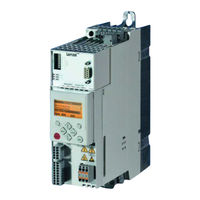
Lenze 8400 StateLine C Reference Manual (891 pages)
L-force Drives; E84AVSC Series;
Brand:
Lenze
| Category:
Inverter Drive
| Size: 9.92 MB
Table of Contents
Table of Contents
3
1 About this Documentation
21
Document History
22
Conventions Used
22
Terminology Used
23
11 Fieldbus Interface.
24
Process Data Transfer
24
Definition of the Notes Used
25
2 Introduction: Parameterising the Controller
26
Integrated Technology Applications
28
Purpose of the Technology Applications
29
Application Cases for a Technology Application
29
Technology Application = Function Block Interconnection
30
Selection of the Appropriate Commissioning Tool
31
Overview: Accessories for Commissioning
32
General Notes on Parameters
33
Changing the Parameterisation with the Keypad
34
Parameters with Subcodes
36
Change Parameter Settings with PC and Lenze Software
37
Save Parameter Settings in the Memory Module Safe against Mains Failure
38
User Menu for Quick Access to Frequently Used Parameters
40
Password Protection
41
Device Personalisation
44
Unlocking the Controller with a Masterpin
46
3 Commissioning
47
Safety Instructions with Regard to Commissioning
48
Notes on Motor Control
49
Preconditions for Commissioning with the »Engineer
50
Trouble-Shooting During Commissioning
51
8400 Commissioning Wizard
52
Commissioning of the "Actuating Drive Speed" Technology Application
52
Prepare Controller for Commissioning
53
Creating an »Engineer« Project and Going Online
53
Parameterising the Motor Control
53
Parameterising the Application
53
Saving Parameter Settings Safe against Mains Failure
54
Prepare Controller for Commissioning
54
Creating an "Engineer« Project and Going Online
55
Parameterising the Motor Control
56
Parameterising the Application
57
Saving Parameter Settings Safe against Mains Failure
59
Commissioning of the "Switch-Off Positioning" Technology Application
61
Prepare Controller for Commissioning
63
Creating an "Engineer« Project and Going Online
64
Parameterising the Motor Control
65
Parameterising the Application
66
Saving Parameter Settings Safe against Mains Failure
68
PC Manual Control
69
Speed Control
72
4 Device Control (DCTRL)
74
Device Commands (C00002/X)
76
Load Lenze Setting
78
Load All Parameter Sets
80
Save All Parameter Sets
81
Enable/Inhibit Controller
82
Activate/Deactivate Quick Stop
83
Reset Error
84
Delete Logbook
84
Device Search Function
85
Device State Machine and Device Statuses
86
Firmwareupdate
87
Init
88
Motorident
89
Safetorqueoff
90
Readytoswitchon
91
Switchedon
92
Operationenabled
93
Warning
93
Troubleqsp
93
Trouble
93
Fault
96
Systemfault
96
Automatic Restart after Mains Connection/Fault
97
Inhibit at Power-On" Auto-Start Option
97
Auto-Start Option "Inhibit at Lenze Setting
99
Internal Interfaces | "Ls_Driveinterface" System Block
100
Wcancontrol/Wmcicontrol Control Words
103
Wdevicestatusword Status Word
104
5 Motor Control (MCTRL)
106
Motor Selection/Motor Data
107
Selecting a Motor from the Motor Catalogue in the
107
Engineer
107
Selecting a Motor from the Motor Catalogue in the "Engineer
110
Automatic Motor Data Identification
112
Selecting the Control Mode
117
Selection Help
117
Defining Current and Speed Limits
122
V/F Characteristic Control
124
Parameterisation Dialog/Signal Flow
126
Basic Settings
128
Defining the V/F Characteristic Shape
129
Defining Current Limits (Imax Controller)
130
Optimising the Control Mode
131
Adapting the V/F Base Frequency
131
Boost
131
Optimising the Imax Controller
131
Adapting the Vmin Boost
134
Optimising the Stalling Behaviour
137
Torque Limitation
138
Defining a User-Defined V/F Characteristic
140
Remedies for Undesired Drive Behaviour
143
V/F Characteristic Control - Energy-Saving (Vfcpluseco)
144
Parameterisation Dialog/Signal Flow
145
Comparison of Vfcpluseco - Vfcplus
147
Basic Settings
148
Optimising the Control Mode
148
Adapting the Slope Limitation for Lowering the Eco Function
149
Optimising the Control Mode
149
Optimising the Cos/Phi Controller
149
Improving the Behaviour at High Dynamic Load Changes
150
Remedies for Undesired Drive Behaviour
152
V/F Control (Vfcplus + Encoder)
154
Parameterisation Dialog/Signal Flow
154
Basic Settings
156
Parameterising the Slip Regulator
157
Sensorless Vector Control (SLVC)
160
Parameterisation Dialog/Signal Flow
161
Types of Control
163
Torque Control with Speed Limitation
164
Basic Settings
165
Optimising the Control Mode
166
Optimising Dynamic Performance and Field Weakening Behaviour
168
Optimising the Stalling Behaviour
169
Optimise Response to Setpoint Changes and Determine Mass Inertia
170
Slip Calculation from Motor Equivalent Circuit Diagram Data
172
Remedies for Undesired Drive Behaviour
173
Sensorless Control for Synchronous Motors (SLPSM)
174
Parameterisation Dialog/Signal Flow
176
Types of Control
179
Basic Settings
180
Optimising the Control Mode
181
Optimise Current Controller
182
Optimise Speed Controller
183
Optimise Response to Setpoint Changes and Determine Mass Inertia
187
Setting the Current Setpoint Filter (Band-Stop Filter)
189
Adapting the Max. Acceleration Change (Jerk Limitation)
190
Pole Position Identification Without Motion
191
Parameterisable Additional Functions
193
Operation with Increased Rated Power
196
Correction of the Stator Leakage Inductance
198
Flying Restart Function
200
DC-Injection Braking
203
Manual DC-Injection Braking (DCB)
204
Slip Compensation
207
Oscillation Damping
209
Oscillation Damping Voltage Range
210
Oscillation Damping in the Field Weakening Range
211
Phase Sequence Reversal for Correcting Misconnected UVW Motor Phases
212
Field Weakening for Synchronous Motors
213
Encoder/Feedback System
217
Parameterising Digital Inputs as Encoder Inputs
219
Encoder Evaluation Method
220
Encoder with HTL Level at DI1/DI2
221
Braking Operation/Brake Energy Management
223
Setting the Voltage Source for Braking Operation
225
Selecting the Response to an Increase of the DC-Bus Voltage
226
Inverter Motor Brake
228
Avoiding Thermal Overload of the Brake Resistor
231
Monitoring
232
Device Overload Monitoring (Ixt)
233
Motor Load Monitoring (I2Xt)
234
Motor Temperature Monitoring (PTC)
236
Brake Resistor Monitoring (I2Xt)
237
Motor Phase Failure Monitoring
239
Motor Phse Error Monitoring before Operation
240
Mains Phase Failure Monitoring
242
Maximum Torque Monitoring
243
Encoder Open-Circuit Monitoring
244
Internal Interfaces | System Block "Ls_Motorinterface
245
Internal Status Signals | System Block "Ls_Devicemonitor
251
6 I/O Terminals
253
Digital Terminals
254
Change Function Assignment
257
Using DI1 and DI2 as Digital Inputs
258
Using DI1 and DI2 as Frequency Inputs
259
Using DI1 as a Counter Input
263
Internal Interfaces | System Block "Ls_Digitalinput
266
Output of the Encoder Position of the DI1/DI2 Frequency Input
268
Internal Interface | System Block "Ls_Digitaloutput
272
Analog Terminals
273
Parameterising Analog Input
275
Signal Adaptation by Means of Characteristic
277
Parameterising Analog Output
279
Internal Interfaces | System Block "Ls_Analoginput
280
Configuring Exception Handling of the Output Terminals
281
User-Defined Terminal Assignment
282
Source-Destination Principle
283
Changing the Terminal Assignment with the Keypad
284
Changing the Terminal Assignment with the "Engineer
286
7 Technology Applications
289
Selection of the Technology Application and the Control Mode
290
TA "Actuating Drive Speed
291
Basic Signal Flow
292
Internal Interfaces | Application Block "La_Nctrl
294
Terminal Assignment of the Control Modes
302
Terminals 0
303
Terminals 2
304
Terminals 11
305
Terminal 16
306
Keypad
307
Process Data Assignment for Fieldbus Communication
311
Setting Parameters (Short Overview)
313
Configuration Parameters
315
TA "Switch-Off Positioning
318
Basic Signal Flow
320
Internal Interfaces | Application Block "La_Switchpos
321
Truth Table for Activating the Pre-Switch off
328
Terminal Assignment of the Control Modes
329
Terminals 0
330
Terminals 2
331
Terminals 11
332
Terminal 16
333
Keypad
334
Process Data Assignment for Fieldbus Communication
338
Setting Parameters (Short Overview)
341
Configuration Parameters
343
Generalpurpose
344
Analog Switch
346
Multiplication/Division
347
Binary Delay Element
348
Analog Comparison
349
Analog Signal Monitor
350
8 Basic Drive Functions (MCK
351
Basic Signal Flow
352
Diagnostics & Error Management
380
9 Diagnostics & Error Management
381
LED Status Displays
381
LED Status Displays of the Device Status
382
Drive Diagnostics with the "Engineer
383
Display Details of the Status Determining Error
385
Drive Diagnostics Via Keypad/Bus System
386
Logbook
389
Functional Description
390
Reading out Logbook Entries
391
Exporting Logbook Entries to a File
392
File Logbook in Project
393
Monitoring
394
Monitoring Configuration
395
Setting the Error Response
396
Autofailreset Function
397
Maloperation of the Drive
398
Operation Without Mains Supply
400
Error Messages of the Operating System
401
Structure of the 16-Bit Error Number (Bit Coding)
404
Reset Error Message
405
Export Error Texts
406
Short Overview (A-Z)
407
Cause & Possible Remedies
409
System Block "Ls_Seterror_1
425
10 System Bus "CAN on Board
427
General Information
428
General Data and Application Conditions
429
Communication Time
430
Possible Settings Via DIP Switch
431
Setting the Baud Rate
432
LED Status Displays for the System
433
Going Online Via System Bus (CAN on Board
434
Structure of the CAN Data Telegram
435
Communication Phases/Network
438
Status Transitions
439
Network Management Telegram (NMT
440
Process Data Transfer
442
Available Process Data Objects
443
Identifiers of the Process Data
450
Transmission Type
451
PDO Synchronisation Via Sync Telegram
454
Monitoring of the Rpdos for Data
455
Stateline C | Reference Manual
456
Parameter Data Transfer
457
Identifiers of the Parameter Data
458
Addressing by Means of Index and Subindex
460
Data 1 ... Data
461
Error Messages
462
Parameter Data Telegram
464
Write Parameters
465
Read Block Parameters
466
Monitoring
469
Heartbeat Protocol
471
Telegram Structure
472
Commissioning Example
474
Emergency Telegram
475
Implemented Canopen Objects
476
Working with the FB Editor
720
15 Working with the FB Editor.
721
Basic Components of a Drive Solution
721
What Is a Function Block
722
Parameterisable Function Blocks
723
What Is a Port Block
724
Conventions Used for Input/Output Identifiers
725
Scaling of Physical Units
726
User Interface
727
Toolbar
728
Search Function
729
Level Selection
730
Editor View/Overview
732
Context Menu
733
Overview Window
734
Using the FB Editor as "Viewer
736
Following Connections of Inputs and Outputs
737
Keyboard Commands for Navigation
738
Change Online Display Format
739
Reconfiguring the Predefined Interconnection
741
Inserting a Function Block
742
Inserting a System Block
744
Inserting a Port Block
746
Inserting a Comment
748
Deleting Objects that Are no Longer Required
750
Changing Connector Visibilities
751
Arranging Objects in the Drawing Area
752
Creating/Deleting Connections
753
Creating a Connection Using the Connection Line
755
Creating a Connection Using Port Identifiers
756
Creating a Connection Via Connection Dialog
757
Deleting Connections that Are no Longer Required
758
Changing the Processing Order
759
Copying Interconnection Elements (Across All Devices)
761
Insert Options for Copied Elements
763
Resetting Changed Interconnection
764
Adjusting Online and Offline Interconnection
765
Printing the Interconnection
766
Comparing Interconnections
767
Copying an Interconnection
770
Exporting/Importing an Interconnection
771
Function Library
772
16 Function Library
774
L_Absolute_1
774
L_Addsub_1
775
L_Analogswitch_1
776
L_Analogswitch_2
777
L_Analogswitch_3
778
L_And_1
779
L_And_2
780
L_And_3
781
L_Arithmetik_1
782
L_Arithmetik_2
784
L_Compare_1
786
Function 1: Nin1 = Nin2
787
Function 2: Nin1 > Nin2
788
Function 4: |Nin1| = |Nin2
790
L_Compare_2
791
L_Compare_3
792
L_Dflipflop_1
793
L_Digitaldelay_1
795
L_Digitallogic_1
797
L_Digitallogic_3
799
L_Gainoffset_1
801
L_Gainoffset_2
802
L_Gainoffset_3
803
L_Interpolator_1
804
Signal Interpolation
805
Signal Monitoring
806
L_Jogctrlextension_1
807
L_Mpot_1
809
Activate & Control Motor Potentiometer
811
Deactivate Motor Potentiometer
812
L_Muldiv_1
813
L_Negation_1
814
L_Not_1
815
L_Not_3
816
L_Nset_1
817
Main Setpoint Path
820
JOG Setpoints
821
Skip Frequency Function
822
Ramp Function Generator for the Main Setpoint
825
S-Shaped Ramp
827
L_Offsetgain_1
828
L_Offsetgain_2
829
L_Offsetgainp_1
830
L_Offsetgainp_2
831
L_Offsetgainp_3
832
L_Or_1
833
L_Or_2
834
L_Or_3
835
L_Or_4
836
L_Pctrl_1
837
Control Characteristic
841
Ramp Function Generator
842
Evaluation of the Output Signal
843
Control Functions
844
L_Pt1_1
845
L_Rlq_1
846
L_Signalmonitor_A
847
L_Signalmonitor_B
848
L_Transient_1
849
Function 0: Evaluate Rising Signal Edges
850
Function 2: Evaluate Rising and Falling Signal Edges
851
L_Transient_2
852
L_Transient_3
853
L_Transient_4
854
System Blocks
855
Ls_Analoginput
857
Ls_Disfree
858
Ls_Disfree_A
859
Display of Internal Process Factors in Application Units
860
Ls_Disfree_B
861
Ls_Keypad
862
Ls_Motioncontrolkernel
863
Ls_Parfix
864
Ls_Parfree
865
Ls_Parfree_A
866
Ls_Parfree_B
867
Ls_Parfree_P
868
Ls_Parfree_V
869
Ls_Parreadwrite_1-3
870
Arithmetic Function
872
Ls_Pulsegenerator
874
Ls_Seterror_1
875
Index
876
Advertisement
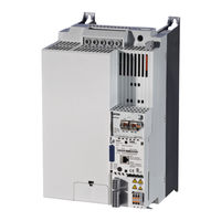
Lenze 8400 StateLine C Hardware Manual (308 pages)
E84A Series
Brand:
Lenze
| Category:
DC Drives
| Size: 5.42 MB
Table of Contents
Table of Contents
3
About this Documentation
8
Document History
8
Conventions Used
9
About this Documentation
9
Terms and Abbreviations Used
10
Notes Used
11
2 Safety Instructions
12
General Safety and Application Notes for Lenze Controllers
12
General Safety and Application Instructions for Lenze Motors
15
Residual Hazards
18
3 Product Description
19
Device Features
19
Overview of Standard Devices
20
Overview of Control Terminals
23
Identification
25
Product Key
26
4 Technical Data
27
General Data and Operating Conditions
27
Technical Data
28
Rated Data
33
Overview
33
Rated Data
34
Operation at Rated Mains Voltage 230 V
36
Operation at Rated Mains Voltage 400 V
40
Operation at a Rated Mains Voltage of 500 V
47
Operation at a Rated Mains Voltage of 500 V
48
Operation with Increased Power at a 230 V Mains
54
Operation with Increased Power at a 400 V Mains
57
Operation with Increased Power at a 500 V Mains
62
Current Characteristics
67
Overcurrent Operation
71
Terminal Description
73
Overview
73
Stateline C Control Terminals
77
External Supply Voltage
77
Analog Inputs
78
Analog Outputs
78
Stateline C Control Terminals
78
Digital Inputs
79
Digital Outputs
79
Connection of Relay Output
79
Highline C Control Terminals
80
External Supply Voltage 24 V
80
Analog Inputs
81
Analog Outputs
81
Digital Inputs
82
Digital Outputs
82
Connection of Relay Output
82
Motor Holding Brake Connection
83
Topline C Control Terminals
84
Axis Bus
84
Multi-Encoder Connection
85
Topline C Control Terminals
85
Resolver Connection
87
5 Mechanical Installation
88
Important Notes
88
Standard Devices in a Power Range of 0.25
89
Assembly in Built-In Technique (Standard)
89
Assembly in Push-Through Technique (Thermal Separation)
98
Assembly in Push-Through Technique (Thermal Separation)
99
Mounting in "Cold Plate" Technique
103
Mounting in "Cold Plate" Technique
104
Standard Devices in the Power Range 3
112
Assembly in Built-In Technique (Standard)
112
Assembly in Push-Through Technique (Thermal Separation)
121
Assembly in Push-Through Technique (Thermal Separation)
122
Mounting in "Cold Plate" Technique
129
Mounting in "Cold Plate" Technique
130
Standard Devices in a Power Range of 30
138
Assembly in Built-In Technique (Standard)
138
Mounting in "Cold Plate" Technique
148
Mounting in "Cold Plate" Technique
149
6 Electrical Installation
153
Important Notes
153
Electrical Installation
154
Electrical Isolation
157
Device Protection
158
Interaction with Compensation Equipment
159
Maximum Motor Cable Length
159
Motor Protection
159
Safety Instructions for the Installation According to UL or UR
160
Safety Instructions for the Installation According to UL or UR
164
Installation According to EMC (Installation of a CE-Typical Drive System)
168
Shielding
168
Mains Connection, DC Supply
170
Motor Cable
171
Control Cables
172
Installation in the Control Cabinet
173
Wiring Outside of the Control Cabinet
175
Detecting and Eliminating EMC Interferences
177
Devices in the Power Range 0.25
178
Example Circuits
178
Terminal Assignment of the Power Connections
182
Terminal Assignment of the Power Connections
183
Devices in the Power Range 0.37
189
Example Circuits
189
Terminal Assignment of the Power Connections
192
Terminal Assignment of the Power Connections
193
Devices in a Power Range of 30
201
Example Circuits
201
Terminal Assignment of the Power Connections
202
Terminal Assignment of the Power Connections
203
Common Control Terminals
211
Important Notes
211
System Bus Connection (Canopen)
215
Connection of Relay Output
221
Connection of Relay Output
222
Diagnostics
223
Stateline C Control Terminals
224
External Supply Voltage 24 V
224
Analog Inputs and Outputs
225
Analog Inputs and Outputs
226
Digital Inputs and Outputs
228
Digital Inputs and Outputs
229
Highline C Control Terminals
230
External Supply Voltage 24 V
230
Analog Inputs and Outputs
232
Analog Inputs and Outputs
233
Digital Inputs and Outputs
235
Digital Inputs and Outputs
236
Motor Holding Brake Connection
238
Topline C Control Terminals
239
Resolver Connection
239
Encoder Connection
240
Topline C Control Terminals
240
Axis Bus
241
7 Commissioning
243
Before Switching on
243
Quick Commissioning
246
Keypad Control
247
Terminal Control
249
8 Braking Operation
251
Braking Operation Without Additional Measures
251
Braking Operation with External Brake Resistor
252
Operation at Rated Mains Voltage 230 V
252
Operation at Rated Mains Voltage 400 V
253
Braking Operation with External Brake Resistor
253
Operation at a Rated Mains Voltage of 500 V
254
Selection of the Brake Resistors
255
Rating for Lenze Brake Resistors
256
Wiring of Brake Resistor
258
Operation with Spring-Applied Brake
260
Introduction
260
Rated Data
262
Rated Data
263
Wiring
264
9 Diagnostics
267
Display of Operating Data, Diagnostics
267
Status Display Via Controller Leds
267
Drive Diagnostics Via Keypad
270
10 Safety Engineering
272
Introduction
272
Important Notes
273
Hazard and Risk Analysis
274
Standards
274
Mission Time
275
Acceptance
276
Description
276
Periodic Inspections
276
Basics for Safety Sensors
277
Operating Mode
278
Hardware Revision
280
Technical Data
281
Technical Data
282
Description
284
Electrical Installation
285
Electrical Installation
286
Certification
287
11 Accessories (Overview)
288
Overview
288
Mains Chokes
289
RFI Filter/Mains Filter
291
Sinusoidal Filters
293
External Brake Resistors
294
Memory Module
295
E84Aym10S
295
Communication Modules
296
Keypad
297
Power Supply Units
298
Terminals (Replacement)
299
EMC Accessories
301
Accessories for Applications with Digital Frequency
304
12 Appendix
305
Total Index
305
Validity
307
Td15
308
Lenze 8400 StateLine C Hardware Manual (187 pages)
L-force Drives Frequency Inverter
Brand:
Lenze
| Category:
Controller
| Size: 3.96 MB
Table of Contents
Table of Contents
3
1 About this Documentation
7
Document History
7
Supplemented by Devices of Device Size
7
Conventions Used
8
Terms and Abbreviations Used
9
Notes Used
10
2 Safety Instructions
11
General Safety and Application Notes for Lenze Controllers
11
General Safety and Application Instructions for Lenze Motors
14
Residual Hazards
17
3 Product Description
18
Device Features
18
Overview of Standard Devices
19
Overview of Control Terminals
20
Identification
21
Type Code
22
4 Technical Data
23
General Data and Operating Conditions
23
Rated Data
27
Overview
27
Operation at Rated Mains Voltage 230 V
30
Operation at Rated Mains Voltage 400 V
34
Operation at Rated Mains Voltage 500 V
40
Current Characteristics
46
Overcurrent Operation
50
Terminal Description
52
Overview
52
Stateline C Control Terminals
54
External Supply Voltage 24 V
54
Analog Inputs
55
Analog Outputs
55
Digital Inputs
56
Digital Outputs
56
Relay Output Connection
56
Highline C Control Terminals
57
External Supply Voltage
57
Analog Inputs
58
Analog Outputs
58
Digital Inputs
59
Digital Outputs
59
Relay Output Connection
59
Motor Holding Brake Connection
60
5 Mechanical Installation
61
Important Notes
61
Standard Devices in the Power Range 0.25
62
Assembly in Built−In Technique (Standard)
62
Assembly in Push−Through Technique (Thermal Separation)
68
Mounting in "Cold Plate" Technique
69
Standard Devices in the Power Range 3
71
Assembly in Built−In Technique (Standard)
71
Assembly in Push−Through Technique (Thermal Separation)
77
Mounting in "Cold Plate" Technique
79
6 Electrical Installation
82
Important Notes
82
Electrical Isolation
85
Device Protection
87
Maximum Motor Cable Length
87
Motor Protection
87
Interaction with Compensation Equipment
87
Safety Notes for the Installation According to UL or UR
88
Installation According to EMC (Installation of a Ce−Typical Drive System)
90
Shielding
90
Mains Connection, DC Supply
92
Motor Cables
93
Control Cables
94
Installation in the Control Cabinet
95
Wiring Outside the Control Cabinet
97
Detecting and Eliminating EMC Interferences
99
Devices in the Power Range 0.25
100
Example Circuits
100
Terminal Assignment of the Power Connections
103
Devices in the Power Range 0.37
110
Example Circuits
110
Terminal Assignment of the Power Connections
112
Common Control Terminals
121
Important Notes
121
System Bus Connection (Canopen)
124
Relay Output Connection
125
Diagnostics
127
Stateline C Control Terminals
128
External Supply Voltage 24 V
128
Analog Inputs and Outputs
129
Digital Inputs and Outputs
131
Highline C Control Terminals
133
External Supply Voltage
133
Analog Inputs and Outputs
135
Digital Inputs and Outputs
137
Motor Holding Brake Connection
140
7 Commissioning
141
Before Switching on
141
Quick Commissioning
144
Keypad Control
145
Terminal Control
147
8 Braking Operation
149
Braking Operation Without Additional Measures
149
Braking Operation with External Brake Resistor
150
Operation at Rated Mains Voltage 230 V
150
Operation at Rated Mains Voltage 400 V
151
Braking Operation with External Brake Resistor
151
Operation at Rated Mains Voltage 500 V
152
Selection of the Brake Resistors
153
Rating for Lenze Brake Resistors
154
Wiring of Brake Resistor
155
Operation with Spring−Applied Brake
157
Introduction
157
Rated Data
159
Wiring
161
9 Diagnostics
163
Display of Operating Data, Diagnostics
163
Status Display Via Leds at the Controller
163
Drive Diagnostics Via Keypad
165
10 Safety Engineering
167
Introduction
167
Important Notes
168
Hazard and Risk Analysis
169
Standards
169
Overview of Sensors
170
Operating Mode
171
Technical Data
172
Electrical Installation
173
Certification
174
11 Accessories (Overview)
175
Overview
175
Mains Chokes
176
RFI Filters
177
Sinusoidal Filters
178
External Brake Resistors
179
Memory Module
180
Communication Modules
181
Keypad
182
Power Supply Units
183
12 Appendix
184
Total Index
184
Advertisement
Advertisement
Related Products
Lenze 8400 motec Series
Lenze 8400 HighLine C Series
Lenze 8601 E.2X.2X
Lenze 8607 E.2X.2X
Lenze 8606 E.2X.2X
Lenze 8609 E.2X.2X
Lenze 8612 E.2X.2X
Lenze 8613 E.2X.2X
Lenze 8300 Series
Lenze 8303 A.0.2 Series
Lenze Categories
DC Drives
Control Unit
Inverter
Engine
Controller
More Lenze Manuals
Login
Sign In
OR
Sign in with Facebook
Sign in with Google
Upload manual
Upload from disk
Upload from URL