Sign In
Upload
Manuals
Brands
Lenze Manuals
Inverter Drive
8400 motec Series
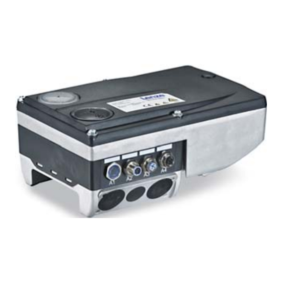
Lenze 8400 motec Series Inverter Manuals
Manuals and User Guides for Lenze 8400 motec Series Inverter. We have
14
Lenze 8400 motec Series Inverter manuals available for free PDF download: Reference Manual, Software Manual, Mounting Instructions, Hardware Manual, Communications Manual
Lenze 8400 motec Series Reference Manual (518 pages)
Inverter Drives
Brand:
Lenze
| Category:
Inverter
| Size: 4 MB
Table of Contents
Table of Contents
3
1 About this Documentation
10
Document History
10
Conventions Used
11
Terminology Used
12
Definition of the Notes Used
14
2 Introduction: Parameterising the Controller
16
Integrated Technology Applications
18
Selection of the Appropriate Commissioning Tool
19
Overview: Accessories for Commissioning
20
General Notes on Parameters
21
Changing the Parameterisation with the Keypad
22
Change Parameter Settings with PC and Lenze Software
25
User Menu for Quick Access to Frequently Used Parameters
26
Handling the Memory Module
27
Device Identification
29
Automatic Acceptance of the Device Name in the »Engineer
29
3 Commissioning
30
Safety Instructions with Regard to Commissioning
31
Preconditions for Commissioning with the »Engineer
32
Trouble-Shooting During Commissioning
32
Commissioning Wizard 8400
33
Commissioning of the "Actuating Drive Speed" Technology Application
34
Prepare Controller for Commissioning
35
Creating an »Engineer« Project & Going Online
36
Parameterising the Motor Control
37
Parameterise Application
39
Saving Parameter Settings Safe against Mains Failure
41
Enabling Controller and Selecting Speed
41
Commissioning of the "Switch-Off Positioning" Technology Application
42
Prepare Controller for Commissioning
44
Creating an »Engineer« Project & Going Online
45
Parameterising the Motor Control
46
Parameterise Application
48
Saving Parameter Settings Safe against Mains Failure
50
Enable Controller and Test Application
50
PC Manual Control
51
Control Via Field Package ("Key-Operated Switch Operation")
55
4 Device Control (DCTRL)
58
Device Commands (C00002/X)
60
Load Lenze Setting
62
Load Parameter Set 1
63
Save Parameter Settings
64
Importing EPM Data
64
Enable/Inhibit Controller
65
Activate/Deactivate Quick Stop
65
Reset Error
66
Delete Logbook
66
Motor Parameter Identification
67
CAN Reset Node
67
Device Search Function
68
Device State Machine and Device States
69
Init
71
Motorident
72
Safetorqueoff
72
Readytoswitchon
73
Switchedon
74
Operationenabled
75
Trouble
76
Fault
77
Auto-Start Option "Inhibit at Power-On
78
5 Motor Control (MCTRL)
80
Special Features of the 8400 Motec
81
Motor Selection/Motor Data
82
Selecting a Motor from the Motor Catalogue in the »Engineer
86
Automatic Motor Data Identification
88
Selecting the Control Mode
90
Selection Help
93
Defining Current and Speed Limits
94
V/F Characteristic Control (Vfcplus)
96
Parameterisation Dialog/Signal Flow
96
Basic Settings
98
Defining the V/F Characteristic Shape
98
Defining Current Limits (Imax Controller)
99
Optimising the Control Mode
100
Adapting the V/F Base Frequency
101
Adapting the Vmin Boost
102
Optimising the Imax Controller
103
Torque Limitation
104
Remedies for Undesired Drive Behaviour
105
V/F Characteristic Control - Energy-Saving (Vfcpluseco)
106
Parameterisation Dialog/Signal Flow
107
Comparison of Vfcpluseco - Vfcplus
109
Basic Settings
110
Optimising the Control Mode
111
Adapting the Slope Limitation for Lowering the Eco Function
112
Improving the Behaviour at High Dynamic Load Changes
112
Optimising the Cos/Phi Controller
113
Remedies for Undesired Drive Behaviour
114
V/F Control (Vfcplus + Encoder)
115
Parameterisation Dialog/Signal Flow
116
Basic Settings
118
Parameterising the Slip Regulator
119
Sensorless Vector Control (SLVC)
122
Parameterisation Dialog
123
Speed Control with Torque Limitation
124
Basic Settings
125
Optimising the Control Mode
125
Optimising the Starting Performance after a Controller Enable
125
Remedies for Undesired Drive Behaviour
126
Sensorless Control for Synchronous Motors (SLPSM)
127
Parameterisation Dialog/Signal Flow
129
Types of Control
132
Basic Settings
133
Optimising the Control Mode
134
Optimise Current Controller
135
Optimise Speed Controller
135
Current-Dependent Stator Leakage Inductance Ppp(I)
139
Field Weakening for Synchronous Motors
141
Parameterisable Additional Functions
145
Selection of Switching Frequency
145
Flying Restart Function
148
DC-Injection Braking
150
Automatic DC-Injection Braking (Auto DCB)
151
Manual DC-Injection Braking (DCB)
151
Slip Compensation
154
Oscillation Damping
155
Mass Inertia Precontrol
156
Encoder/Feedback System
158
Encoder Evaluation Method
161
Braking Operation/Brake Energy Management
163
Settings for Internal Brake Resistor E84Dzewxxxx
164
Voltage Limits for Braking Operation
164
Response to an Increase of the DC-Bus Voltage
164
Inverter Motor Brake
166
Degradation of Braking Energy by Motor Overmagnetisation
169
Power and Energy Display
170
Monitoring
171
Device Overload Monitoring (Ixt)
172
Motor Load Monitoring (I2Xt)
173
Motor Temperature Monitoring (PTC)
176
Brake Resistor Monitoring (I2Xt)
177
Mains Phase Failure Monitoring
179
Maximum Current Monitoring
179
Motor Speed Monitoring
180
Encoder Open-Circuit Monitoring
180
6 O Terminals
181
Digital Terminals
182
Configuring DI1 and DI2 as Frequency Inputs
185
Analog Terminals
188
Parameterising Analog Input
189
User-Defined Terminal Assignment
191
Source-Destination Principle
192
Changing the Terminal Assignment with the »Engineer
193
Changing the Terminal Assignment Via Configuration Parameters
194
Electrical Data
197
7 Technology Applications
199
Selection of the Technology Application and the Control Mode
200
TA "Actuating Drive Speed
201
Basic Signal Flow
202
Generalpurpose" Functions
205
Interface Description
206
Wdrivecontrol Control Word
211
Wdevicestateword Status Word
212
Terminal Assignment of the Control Modes
214
Terminals 0
214
Terminals 0
215
Terminals 11
215
Terminals 2
215
Terminal 16
216
Terminals 11
216
Network (MCI/CAN)
217
Network (AS-I)
218
Setting Parameters (Short Overview)
219
Pre-Assignment of the Application
220
Input Connections
220
Output Connections
223
Internal Signal Flow for Control Via Terminals
225
Internal Signal Flow for Control Via Network (MCI/CAN)
226
Internal Signal Flow for Control Via Network (AS-I)
227
TA "Actuating Drive Speed (AC Drive Profile)
229
Basic Signal Flow
230
Scaling of the Speed and Torque Values (Ref from Net)
232
Interface Description
234
AC Drive Profile" Control Word
234
AC Drive Profile" Status Word
235
Setting Parameters (Short Overview)
235
Internal Signal Flow
236
TA "Switch-Off Positioning
238
Functional Principle
240
Basic Signal Flow
242
Interface Description
244
Wdrivecontrol Control Word
244
Wdevicestateword Status Word
245
Terminal Assignment of the Control Modes
246
Terminals 0
246
Terminals 2
246
Terminals 0
247
Terminals 11
247
Terminals 11
249
Terminal 16
250
Network (MCI/CAN)
251
Network (AS-I)
252
Setting Parameters (Short Overview)
253
Pre-Assignment of the Application
254
Input Connections
254
Output Connections
257
Internal Signal Flow for Control Via Terminals
259
Internal Signal Flow for Control Via Network (MCI/CAN)
260
Internal Signal Flow for Control Via Network (AS-I)
261
Advertisement
Lenze 8400 motec Series Software Manual (376 pages)
L-force series
Brand:
Lenze
| Category:
Inverter Drive
| Size: 5 MB
Table of Contents
Table of Contents
3
1 About this Documentation
10
Document History
10
Conventions Used
11
Terminology Used
12
Operating Mode
13
Definition of the Notes Used
14
2 Introduction: Parameterising the Controller
15
General Notes on Parameters
16
Handling the Memory Module
17
Engineer
18
3 Commissioning
19
Safety Instructions with Regard to Commissioning
20
LED Status Display
21
Commissioning with the »Engineer
22
Preconditions for Commissioning with the »Engineer
22
Preparing the 8400 Motec for Commissioning
23
Creating an »Engineer« Project & Going Online
24
Parameterising the Motor Control
25
Engineer
26
Parameterising the Application
27
Engineer
28
Saving Parameter Settings Safe against Mains Failure
29
Enabling Controller and Selecting Speed
29
Engineer
30
4 Device Control (DCTRL)
31
Device State Machine and Device States
31
Engineer
32
Device Commands (C00002/X)
33
Engineer
34
Load Lenze Setting
35
Load Parameter Set 1
36
Save Parameter Settings
37
Enable/Inhibit Controller
38
Importing EPM Data
38
Activate/Deactivate Quick Stop
39
Reset Error
39
CAN Reset Node
40
Delete Logbook
40
Identify Motor Parameter
40
Init
43
Motorident
44
Safetorqueoff
44
Readytoswitchon
45
Switchedon
46
Operationenabled
47
Trouble
48
Fault
49
Auto-Start Option "Inhibit at Power-On
50
5 Motor Control (MCTRL)
52
Special Features of the 8400
52
Motor Selection/Motor Data
52
Selecting a Motor from the Motor Catalogue in the
54
Engineer
54
Engineer
55
Error
56
Selecting a Motor from the Motor Catalogue in the "Engineer
57
Automatic Motor Data Identification
59
Drive
60
Selecting the Control Mode
61
Drive
62
Selection Help
63
Defining Current and Speed Limits
64
V/F Characteristic Control
65
Parameterisation Dialog/Signal Flow
67
Basic Settings
69
Defining the V/F Characteristic Shape
69
Defining Current Limits (Imax Controller)
70
Optimise Control Behaviour
71
Adapting the V/F Base Frequency
71
Optimising the Imax Controller
71
Adapting the Vmin Boost
73
Torque Limitation
75
Remedies for Undesired Drive Behaviour
76
V/F Characteristic Control - Energy-Saving (Vfcpluseco)
77
Parameterisation Dialog/Signal Flow
78
Comparison of Vfcpluseco - Vfcplus
80
Basic Settings
81
Optimise Control Behaviour
81
Improving the Behaviour at High Dynamic Load
82
Changes
85
Optimising the Cos/Phi Controller
85
Remedies for Undesired Drive Behaviour
85
V/F Control (Vfcplus + Encoder)
86
Parameterisation Dialog/Signal Flow
87
Basic Settings
89
Parameterising the Slip Regulator
90
Drive
91
Drive
92
Sensorless Vector Control
93
Parameterisation Dialog
94
Speed Control with Torque Limitation
95
Basic Settings
96
Optimise Control Behaviour
96
Optimising the Starting Performance after a Controller Enable
96
Remedies for Undesired Drive Behaviour
97
Parameterisable Additional Functions
98
Selection of Switching Frequency
98
Error
99
Flying Restart Function
100
Drive
101
DC-Injection Braking
102
Manual DC-Injection Braking (DCB)
102
Automatic DC-Injection Braking (Auto-DCB)
103
Drive
104
Slip Compensation
105
Oscillation Damping
106
Encoder/Feedback System
107
Engineer
108
Encoder Evaluation Method
109
Engineer
109
Error
111
Braking Operation/Braking Energy Management
112
Settings for Internal Brake Resistor E84Dzewxxxx
113
Voltage Limits for Braking Operation
113
Response to an Increase of the DC-Bus Voltage
114
Inverter Motor Brake
116
Operating Mode
117
Degradation of Braking Energy by Motor Overmagnetisation
119
Power and Energy Display
120
Monitoring
121
Motor Load Monitoring (I2Xt)
121
Motor Temperature Monitoring (PTC)
121
Brake Resistor Monitoring (I2Xt)
121
Mains Phase Failure Monitoring
121
Encoder Open-Circuit Monitoring
121
Device Overload Monitoring (Ixt)
122
Error
124
6 O Terminals
131
Digital Terminals
131
Engineer
132
Configuring DI1 and DI2 as Frequency Inputs
133
Drive
133
Response
135
Analog Terminals
137
Parameterising Analog Input
137
User-Defined Terminal Assignment
137
Source-Destination Principle
140
Changing the Terminal Assignment with the »Engineer
141
Changing the Terminal Assignment Via Configuration Parameters
142
Electrical Data
145
Error
146
7 Drive Application
147
Parameterisation Dialog
148
Drive
149
Signal Flow
150
Generalpurpose" Functions
150
Process Controller
150
Interface Description
150
Operating Mode
151
Selection of the Main Speed Setpoint
152
Error
155
Drive
156
Operating Mode
157
Error
158
Functional Settings
159
Wdrivecontrol Control Word
160
Wdevicestateword Status Word
161
Setting Parameters (Short Overview)
162
Pre-Assignment of the Drive Application
163
Input Connections
163
Output Connections
164
Internal Signal Flow for Control Via Terminals
165
Internal Signal Flow for Control Via Network (MCI/CAN)
166
Terminal Assignment of the Control Modes
168
Terminals 11
168
Terminals 16
168
Terminals 0
168
Network (MCI/CAN)
170
8 Basic Functions
171
Parameter Change-Over
172
Configuring the List Using the »Engineer« Parameterisation Dialog
172
Drive
173
Configuring the List by Means of Parameterisation
175
Selecting a Value Set
176
Operating Mode
179
Parameters
180
Holding Brake Control
180
Operating Mode
180
Functional Settings
182
Switching Thresholds
183
Applying and Releasing Time
185
Motor Magnetising Time (Only with Asynchronous Motor)
187
Monitoring
187
Process When Brake Is Released
188
Drive
188
Process When Brake Is Closed
189
Actual Value Monitoring
189
Actual Value Monitoring
190
Behaviour in Case of Pulse Inhibit
191
Feedforward Control of the Motor before Release
192
Lenze 8400 motec Series Mounting Instructions (264 pages)
Brand:
Lenze
| Category:
DC Drives
| Size: 8 MB
Table of Contents
Deutsch
5
Table of Contents
5
1 Über diese Dokumentation
6
Dokumenthistorie
6
Zielgruppe
7
Informationen zur Gültigkeit
8
Verwendete Konventionen
8
Verwendete Hinweise
9
2 Sicherheitshinweise
11
Allgemeine Sicherheitshinweise
11
Sicherheitshinweise für die Installation nach UL/CSA
12
3 Technische Daten
16
Allgemeine Daten und Einsatzbedingungen
16
Bemessungsdaten
21
4 Mechanische Installation
22
Vorbereitung
22
Montage
23
Maßnahme bei Einsatz in It−Netzen
25
5 Einstellungen
27
Dip−Schalter−/ Potibelegung 0
31
Dip−Schalter−/ Potibelegung 1
35
Dip−Schalter−/ Potibelegung 2
39
6 Inbetriebnahme
40
Vor dem Ersten Einschalten
40
Inbetriebnahmeschritte
41
Inbetriebnahme mit Handterminal
43
Menüstruktur
44
User Menü
44
Inbetriebnahmeschritte
46
Set−Modus
50
7 Parametrierung
52
English
55
1 About this Documentation
56
Document History
56
Target Group
57
Validity Information
58
Conventions Used
58
Notes Used
59
2 Safety Instructions
61
General Safety Instructions
61
Safety Instructions for the Installation According to UL/CSA
62
3 Technical Data
66
General Data and Operating Conditions
66
Rated Data
71
4 Mechanical Installation
72
Preparation
72
Mounting
73
Measures When Drive Is Used in IT Systems
75
5 Settings
77
DIP Switch / Potentiometer Assignment 0
81
DIP Switch / Potentiometer Assignment 1
86
DIP Switch / Potentiometer Assignment 2
90
6 Commissioning
91
Before Switching on
91
Commissioning Steps
92
Commissioning Via the Diagnosis Terminal
94
Menu Structure
95
User Menu
95
Commissioning Steps
97
SET Mode
101
7 Parameter Setting
103
Français
105
1 Présentation du Document
106
Historique du Document
106
Public Visé
107
Validité
108
Conventions Utilisées
108
Consignes Utilisées
109
2 Consignes de Sécurité
111
Consignes Générales
111
Consignes de Sécurité Pour L'installation Selon UL / CSA
112
3 Spécifications Techniques
116
Caractéristiques Générales Et Conditions D'utilisation
116
Caractéristiques Assignées
121
4 Installation Mécanique
122
Préparation
122
Montage
123
Mesure À Prévoir Lors de L'utilisation Dans des Réseaux IT
125
5 Réglages
127
Affectation du Commutateur DIP / Potentiomètre 0
133
Affectation du Commutateur DIP / Potentiomètre 1
138
Affectation du Commutateur DIP / Potentiomètre 2
143
6 Mise en Service
144
Avant la Première Mise Sous Tension
144
Etapes de Mise en Service
146
Mise en Service Avec Clavier de Commande Avec Support
148
Navigation Facilitée Par Menus
149
Menu Utilisateur
149
Opérations de Mise en Service
151
Mode SET
155
7 Paramétrage
157
Advertisement
Lenze 8400 motec Series Hardware Manual (172 pages)
L-force Drives
Brand:
Lenze
| Category:
Inverter Drive
| Size: 4 MB
Table of Contents
Table of Contents
3
1 About this Documentation
7
Validity Information
7
Document History
8
Conventions Used
9
Terms and Abbreviations Used
10
Notes Used
11
2 Safety Instructions
12
General Safety and Application Notes for Lenze Controllers
12
General Safety and Application Notes for Lenze Motors
15
Residual Hazards
18
3 Product Description
19
System Overview
19
Device Features
20
Identification
22
Product Key
23
Wiring Unit
23
Frame Unit
24
Communication Unit
25
Drive Unit
25
8400 Motec Set
26
Field Package Without Switch
27
Field Package with Switch
28
Overview of Control Terminals
29
4 Technical Data
30
General Data and Operating Conditions
30
Rated Data
35
Overview
35
Operation at Rated Mains Voltage 400 V
37
Operation with Increased Power at a 400 V Mains
39
Operation with Rated Mains Voltage 480 V
41
Operation with Increased Power on a 480 V System
43
Device Protection by Current Derating
45
Frame Unit / Field Package Without Switch
45
Frame Unit / Field Package with Switch
47
Overcurrent Operation
49
Switching Frequency Reduction
51
Power Terminals
52
8400 Motec 0.37
52
8400 Motec 4
55
8400 Motec Field Package
58
Control Terminals
61
Overview
61
General Data
62
As−Interface
63
Canopen
64
Ethercat
64
Ethernet/Ip™
65
Profibus
65
Profinet
66
Dimensions
67
Standard Motor Mounting
67
Field Package Without Switch
68
Field Package with Switch
69
5 Installation
70
Important Notes
70
Safety Instructions for the Installation According to UL/CSA
73
Installation According to EMC (Installation of a Ce−Typical Drive System)
75
Shielding
75
Motor Cable
76
Control Cables
77
Detecting and Eliminating EMC Interferences
77
Installation of 8400 Motec Pre−Assembled on the Motor
78
Installation Instructions
78
Plug at the Wiring Unit
78
Attaching the Cable Gland
79
Retrofitting the 8400 Motec Controller
81
Installation Instructions
81
Preparing a Motor for the 8400 Motec Installation
81
Mounting the Wiring Unit
82
Mounting of the Communication Unit
84
Settings at the Drive Unit
85
Mounting of the Drive Unit
85
Measures When Drive Is Used in IT Systems
86
Wall Mounting
87
Installation Instructions
87
Wall Adapter for 0.37
88
Wall Adapter for 4
89
Frame Unit / Field Package Without Switch
90
Frame Unit / Field Package with Switch
90
Power Terminals
91
Control Terminals
94
Basic I/O
94
Standard I/O
95
Extended I/O
96
As−Interface
97
As−Interface STO
99
Canopen
101
Canopen® STO
103
Ethercat
105
Ethercat® STO
107
Ethernet/Ip™
109
Ethernet/Ip™ STO
111
Profibus
113
Profibus® Sto
115
Profinet
117
Profinet® Sto
119
Lenze 8400 motec Series Hardware Manual (124 pages)
L-force Drives. Decentralised frequency inverter. 0.37 ... 7.5 kW. E84DG series
Brand:
Lenze
| Category:
DC Drives
| Size: 2 MB
Table of Contents
Table of Contents
3
1 About this Documentation
7
Validity Information
7
Document History
8
Conventions Used
9
Terms and Abbreviations Used
10
Notes Used
11
2 Safety Instructions
12
General Safety and Application Notes for Lenze Controllers
12
General Safety and Application Instructions for Lenze Motors
15
Residual Hazards
18
3 Product Description
19
System Overview
19
Device Features
20
Identification
21
Type Code
22
Introducing Information
22
The Type Codes
22
Overview of Control Terminals
25
4 Technical Data
26
General Data and Operating Conditions
26
Rated Data
31
Overview
31
Operation at Rated Mains Voltage 400 V
33
Operation at Increased Rated Power at 400 V Mains Voltage
35
Operation with Rated Mains Voltage 480 V
37
Switching Frequency Reduction
39
Overcurrent Operation
40
Terminal Description
42
Overview
42
Power Terminals
44
Mains Connection
45
Motor Connection
45
Motor Temperature Monitoring
45
Motor Holding Brake Connection
45
Connection of Brake Resistor
45
Control Terminals
46
Digital Inputs
48
Digital Output
50
Analog Input
50
Connection of Relay Output
50
Communication Connection
51
Dimensions
52
Standard Motor Mounting
52
Wall Mounting
53
5 Installation
54
Important Notes
54
Safety Instructions for the Installation According to UL/CSA
57
Safety Instructions for the Installation According to UL/CSA
58
Installation According to EMC (Installation of a CE-Typical Drive System)
59
Shielding
59
Motor Cable
60
Control Cables
61
Detecting and Eliminating EMC Interferences
61
Mechanical Installation
62
Electrical Installation
63
Power Connections
63
Wiring of Control Connections
64
Installation of 8400 Motec Pre-Assembled on the Motor
66
Plug at the Wiring Unit
66
Attaching the Cable Gland
67
Retrofitting the 8400 Motec Controller
69
Preparing a Motor for the 8400 Motec Installation
69
Mounting the Wiring Unit
70
Mounting of the Communication Unit
71
Settings at the Drive Unit
72
Mounting of the Drive Unit
72
Measures When Drive Is Used in IT Systems
74
Wall Mounting of 8400 Motec Controller
75
Lenze 8400 motec Series Mounting Instructions (128 pages)
L-force Drives / Drive Unit
Brand:
Lenze
| Category:
DC Drives
| Size: 4 MB
Table of Contents
Deutsch
4
Table of Contents
4
1 Über diese Dokumentation
5
Dokumenthistorie
5
Zielgruppe
5
Informationen zur Gültigkeit
5
Verwendete Konventionen
6
Verwendete Hinweise
7
2 Sicherheitshinweise
9
3 Technische Daten
10
Allgemeine Daten und Einsatzbedingungen
10
Bemessungsdaten
13
4 Mechanische Installation
14
Vorbereitung
14
Montage
15
5 Parametrierung
16
6 Einstellungen
17
Grundeinstellungen
19
Einstellen mit dem Handterminal (Keypad)
21
Maßnahme bei Einsatz in It−Netzen
23
7 Inbetriebnahme
24
English
28
1 About this Documentation
29
Document History
29
Target Group
29
Validity Information
29
Conventions Used
30
Notes Used
31
2 Safety Instructions
33
3 Technical Data
34
General Data and Operating Conditions
34
Rated Data
37
4 Mechanical Installation
38
Preparation
38
Mounting
39
5 Parameter Setting
40
6 Settings
41
Basic Settings
43
Setting with the Diagnosis Terminal (Keypad)
45
Measures When Drive Is Used in IT Systems
47
7 Commissioning
48
Français
52
1 Présentation du Document
53
Historique du Document
53
Public Visé
53
Validité
53
Conventions Utilisées
54
Consignes Utilisées
55
2 Consignes de Sécurité
57
3 Spécifications Techniques
58
Caractéristiques Générales Et Conditions D'utilisation
58
Caractéristiques Assignées
62
4 Installation Mécanique
63
Préparation
63
Montage
64
5 Paramétrage
65
6 Réglages
66
Réglages de Base
68
Réglages À L'aide du Clavier de Commande Avec Support de Protection
71
Mesure À Prévoir Lors de L'utilisation Dans des Réseaux IT
73
7 Mise en Service
74
Lenze 8400 motec Series Communications Manual (111 pages)
CANopen communication unit
Brand:
Lenze
| Category:
Conference System
| Size: 1 MB
Table of Contents
Table of Contents
3
1 About this Documentation
6
Document History
8
Conventions Used
9
Terminology Used
10
Notes Used
11
2 Safety Instructions
12
General Safety and Application
12
Instructions
12
Device and Application-Specific Safety Instructions
13
Residual Hazards
13
3 Product Description
14
Application as Directed
14
Product Features and Variants
15
Connections and Interfaces
17
4 Technical Data
19
General Data and Operating Conditions of the Canopen
19
Supported Protocols
20
Communication Time
21
5 Installation
22
Mechanical Installation
23
Electrical Installation
24
Network Topology
24
Bus Termination
25
Specification of the Bus Cable
26
Bus Cable Length
26
Canopen Connection
29
6 Commissioning
30
Before Initial Switch-On
30
Configuring the Host
31
(Master)
31
Possible Settings Via DIP Switch
32
Setting the Baud Rate
32
Setting the CAN Node Address
33
Settings in the Lenze »Engineer
34
Switch-On
34
7 Data Transfer
36
Structure of the CAN Data Telegram
36
Identifier
37
User Data
39
Communication Phases/Network
40
Management
40
Network Management Telegram (NMT)
42
Parameterising the Inverter Drives 8400 Motec as CAN Master
43
8 Process Data Transfer
44
Access to Process Data / PDO Mapping
46
Port Interconnection of the Process Data Objects (PDO)
47
Identifiers of the Process Data Objects
51
Transmission Type
52
PDO Synchronisation Via Sync
54
Telegram
54
Lenze 8400 motec Series Communications Manual (109 pages)
CANopen Inverter Drives
Brand:
Lenze
| Category:
DC Drives
| Size: 1 MB
Table of Contents
Table of Contents
2
1 About this Documentation
5
Document History
7
Conventions Used
8
Terminology Used
9
Notes Used
10
2 Safety Instructions
11
General Safety and Application Notes
11
Device and Application-Specific Safety Instructions
12
Residual Hazards
12
3 Product Description
13
Application as Directed
13
Features and Variants
14
Connections and Interfaces
16
4 Technical Data
18
General Data and Operating Conditions of the Canopen
18
Supported Protocols
19
Communication Time
20
5 Installation
21
Mechanical Installation
22
Electrical Installation
23
Network Topology
23
Bus Termination
24
Specification of the Bus Cable
25
Bus Cable Length
25
Canopen Connection
28
6 Commissioning
29
Before Initial Switch-On
29
How to Configure the Host (Master)
30
Possible Settings Via DIP Switch
31
Setting the Baud Rate
31
Setting the CAN Node Address
32
Settings in the Lenze »Engineer
33
Initial Switch-On
34
7 Data Transfer
35
Structure of the CAN Data Telegram
35
Identifier
36
User Data
37
Communication Phases/Network Management
37
State Transitions
39
Network Management Telegram (NMT)
40
Parameterising the Inverter Drives 8400 Motec as CAN Master
41
8 Process Data Transfer
42
Accessing Process Data / PDO Mapping
44
Port Interconnection of Process Data Objects (PDO)
45
Identifiers of the Process Data Objects
49
Transmission Type
50
PDO Synchronisation Via Sync Telegram
52
9 Parameter Data Transfer
53
Identifiers of the Parameter Data Objects
54
User Data
55
Command
55
Addressing by Means of Index and Subindex
56
Data 1
57
Error Messages
58
Parameter Data Telegram Examples
60
Read Parameters
60
Write Parameters
61
Reading Block Parameters
62
Lenze 8400 motec Series Communications Manual (76 pages)
EtherCAT Communication Unit
Brand:
Lenze
| Category:
Control Unit
| Size: 1 MB
Table of Contents
Table of Contents
3
1 About this Documentation
5
Document History
7
Conventions Used
8
Terminology Used
9
Notes Used
10
2 Safety Instructions
11
General Safety and Application Notes
11
Device and Application-Specific Safety Instructions
12
Residual Hazards
12
3 Product Description
13
Application as Directed
13
Features and Variants
14
Connections and Interfaces
15
4 Technical Data
17
General Data and Operating Conditions
17
Protocol Data
18
Communication Time
18
5 Installation
19
Mechanical Installation
20
Electrical Installation
21
Network Topology
21
Ethercat Connection
23
External Voltage Supply
24
6 Commissioning
25
Before Initial Switch-On
25
Configuring the Host
26
(Master)
26
Installing Device Description Files
26
Automatic Device Identification
27
Configuring Process Data
28
Determining the Cycle Time
29
Address Allocation
30
Switch-On
31
7 Data Transfer
32
Ethercat Frame Structure
33
Ethercat Datagrams
34
Ethercat State Machine
35
8 Process Data Transfer
37
Accessing Process Data / PDO Mapping
38
Configuring the Port Interconnection of the Process Data Objects (PDO)
39
9 Parameter Data Transfer
43
Establishing a Connection between Master and
43
Slave
43
Reading and Writing Parameters
44
Reading Parameters
45
Upload)
45
Writing Parameters (SDO Download)
49
Implemented Coe Objects
53
Ethercat Objects of the Communication Unit
54
SDO Abort Codes (Abort Codes)
55
Lenze 8400 motec Series Communications Manual (74 pages)
AS-Interface Inverter Drives
Brand:
Lenze
| Category:
DC Drives
| Size: 0 MB
Table of Contents
Table of Contents
2
1 About this Documentation
4
Document History
6
Conventions Used
7
Terminology Used
8
Notes Used
9
2 Safety Instructions
10
General Safety and Application Notes
10
Device and Application-Specific Safety Instructions
11
Residual Hazards
11
3 Product Description
12
Application as Directed
12
Features and Variants
13
Connections and Interfaces
14
4 Technical Data
16
General Data and Operating Conditions
16
Protocol Data
17
Communication Time
18
5 Installation
19
Mechanical Installation
20
Electrical Installation
21
Bus Cable Specification
21
AS-I Connection
22
Voltage Supply
23
6 Commissioning
24
Before Initial Switch-On
24
How to Configure the Host (Master)
25
Settings for AS-I Communication in the "Engineer
26
Addressing the AS-I Slaves
26
All Parameters for Setting the AS-I Communication
27
Initial Switch-On
28
7 Data Transfer
29
AS-I Messages
29
AS-I Cycle
31
Synchronisation
32
AS-I Concept of the Communication Unit
33
Data Transmission Slave 1 (AS-I Profile 7.A.5)
34
Data Transmission Slave 2 (AS-I Profile 7.A.E)
36
8 Process Data Transfer
38
Accessing Process Data / PDO Mapping
39
Port Interconnection of Process Data Objects (PDO)
40
9 Parameter Data Transfer
43
CTT2: Read Parameter Value
44
CTT2: Write Parameter Value
45
CTT2: Read Code Number
46
CTT2: Write Code Number
47
CTT2: Block Parameter Transfer
48
Read Mode
48
Write Mode
50
CTT2: Standard Error Codes
51
CTT2: Acyclic Device Error Codes
52
Lenze 8400 motec Series Mounting Instructions (32 pages)
Frame Unit with switch
Brand:
Lenze
| Category:
DC Drives
| Size: 3 MB
Lenze 8400 motec Series Mounting Instructions (24 pages)
Frame Unit without switch
Brand:
Lenze
| Category:
Inverter
| Size: 2 MB
Lenze 8400 motec Series Mounting Instructions (14 pages)
Frame Unit with switch
Brand:
Lenze
| Category:
Inverter Drive
| Size: 0 MB
Lenze 8400 motec Series Mounting Instructions (14 pages)
Plug in modules
Brand:
Lenze
| Category:
Control Unit
| Size: 0 MB
Advertisement
Related Products
Lenze 8400 StateLine C
Lenze 8400 HighLine C Series
Lenze 8601 E.2X.2X
Lenze 8607 E.2X.2X
Lenze 8606 E.2X.2X
Lenze 8609 E.2X.2X
Lenze 8612 E.2X.2X
Lenze 8613 E.2X.2X
Lenze 8300 Series
Lenze 8303 A.0.2 Series
Lenze Categories
DC Drives
Control Unit
Inverter
Engine
Controller
More Lenze Manuals
Login
Sign In
OR
Sign in with Facebook
Sign in with Google
Upload manual
Upload from disk
Upload from URL