
Related Manuals for Omron R88D-KN01L-ECT-L


Summary of Contents for Omron R88D-KN01L-ECT-L
- Page 1 AC SERVOMOTORS/SERVO DRIVES G5-series WITH BUILT-IN EtherCAT COMMUNICATIONS ® Linear Motor Type User’s Manual R88L-EC- (Linear Motors) R88D-KN -ECT-L (AC Servo Drives) I577-E1-04...
- Page 2 OMRON. No patent liability is assumed with respect to the use of the information contained herein. Moreover, because OMRON is constantly striving to improve its high-quality products, the information contained in this manual is subject to change without notice.
- Page 3 Introduction Introduction Thank you for purchasing a G5-series Servo Drive. This manual explains how to install and wire the Servo Drive, set parameters needed to operate the Servo Drive, and remedies to be taken and inspection methods to be used in case that problems occur. Intended Readers This manual is intended for the following individuals.
- Page 4 Manual Configuration Manual Configuration This manual consists of the following sections. Outline Section 1 Features and This section explains the features of the Servo Drive and name of each System part. Configuration Section 2 Models and This section explains the models of Servo Drive, Linear Motors, and External peripheral devices, and provides the external dimensions and mounting Dimensions...
- Page 5 Manual Structure Manual Structure Page Structure and Symbol Icons The following page structure and symbol icons are used in this manual. Level 1 heading 11 Adjustment Functions 11-8 Disturbance Observer Function Level 2 heading You can use the disturbance force value estimated with the disturbance observer to lower the effect of the disturbance force and reduce vibration.
- Page 6 Terms and Expressions Used for the Linear Motor In this manual, the term “Linear Motor” is defined as an OMRON product that consists of a Motor Coil Unit (the coil on the primary side) and a Magnet Track (the magnets on the secondary side).
- Page 7 Sections in this Manual Sections in this Manual Features and System Operation Configuration Models and External Adjustment Functions Dimensions Troubleshooting and Specifications Maintenance System Design Appendices EtherCAT Index Communications Basic Control Functions Applied Functions Safety Function Servo Parameter Objects G5-series Linear Motors/Servo Drives With Built-in EtherCAT Communications...
- Page 8 CONTENTS CONTENTS Introduction ....................... 1 Manual Configuration ....................2 Manual Structure ....................... 3 Sections in this Manual .................... 5 CONTENTS ........................ 6 Terms and Conditions Agreement................. 12 Safety Precautions ....................14 Regulations and Standards..................24 Items to Check after Unpacking................27 Revision History ......................
- Page 9 CONTENTS Section 3 Specifications Servo Drive Specifications ..................... 3-2 3-1-1 General Specifications........................ 3-2 3-1-2 Characteristics ..........................3-3 3-1-3 EtherCAT Communications Specifications ................. 3-5 3-1-4 EtherCAT Communications Connector Specifications (RJ45)............ 3-5 3-1-5 Control I/O Specifications (CN1)....................3-6 3-1-6 Control Input Circuits ........................3-8 3-1-7 Control Input Details ........................
- Page 10 6-4-3 Controlword (6040 hex) in Profile Position Mode..............6-14 6-4-4 Statusword (6041 hex) in Profile Position Mode ............... 6-14 Homing Mode ......................... 6-15 Connecting with OMRON Controllers.................. 6-16 Section 7 Applied Functions Sequence I/O Signals ......................7-2 7-1-1 Input Signals ..........................7-2 7-1-2 Output Signals..........................
- Page 11 CONTENTS Overrun Protection........................ 7-11 7-3-1 Operating Conditions ........................ 7-11 7-3-2 Objects Requiring Settings ....................... 7-11 7-3-3 Operation Example ........................7-12 Backlash Compensation....................... 7-13 Brake Interlock........................7-15 7-5-1 Objects Requiring Settings ....................... 7-15 7-5-2 Operation Timing ........................7-16 Electronic Gear Function...................... 7-20 7-6-1 Objects Requiring Settings .......................
- Page 12 CONTENTS Section 10 Operation 10-1 Operational Procedure ......................10-2 10-2 Preparing for Operation ......................10-4 10-2-1 Items to Check Before Turning ON the Power Supply.............. 10-4 10-2-2 Turning ON the Power Supply ....................10-6 10-2-3 Checking the Displays....................... 10-6 10-2-4 Preparing the Linear Motor for Operation .................
- Page 13 CONTENTS 11-10Feed-forward Function......................11-32 11-10-1 Objects Requiring Settings ..................... 11-32 11-10-2 Operating Procedure ......................11-33 11-11Instantaneous Speed Observer Function ................. 11-35 11-11-1 Operating Conditions ......................11-35 11-11-2 Objects Requiring Settings ..................... 11-36 11-11-3 Operating Procedure ......................11-36 Section 12 Troubleshooting and Maintenance 12-1 Actions for Problems ......................
- Page 14 Omron’s exclusive warranty is that the Products will be free from defects in materials and workmanship for a period of twelve months from the date of sale by Omron (or such other period expressed in writing by Omron). Omron disclaims all other warranties, express or implied.
- Page 15 Disclaimers Performance Data Data presented in Omron Company websites, catalogs and other materials is provided as a guide for the user in determining suitability and does not constitute a warranty. It may represent the result of Omron’s test conditions, and the user must correlate it to actual application requirements. Actual performance is subject to the Omron’s Warranty and Limitations of Liability.
- Page 16 Safety Precautions Safety Precautions To ensure that the G5-series Servo Drive and Servomotor as well as peripheral equipment are used safely and correctly, be sure to read this Safety Precautions section and the main text before using the product. Learn all items you should know before use, regarding the equipment as well as the required safety information and precautions.
- Page 17 When using this product, be sure to install the covers and shields as specified and use the product according to this manual. • If the product has been stored for an extended period of time, contact your OMRON sales representative.
- Page 18 Safety Precautions Do not enter the operating area during operation. Injury may result. Never modify the Servo Drive. Injury or equipment damage may result. Install a stopping device on the machine to ensure safety. * The holding brake is not a stopping device to ensure safety. Injury may result.
- Page 19 Safety Precautions Caution Do not store or install the Servo Drive in the following locations: • Location subject to direct sunlight • Location where the ambient temperature exceeds the specified level • Location where the relative humidity exceeds the specified level •...
- Page 20 Safety Precautions Storage and Transportation Caution When transporting the Motor Coil Unit, do not hold the cable. Injury or equipment damage may result. When transporting the Magnet Track, do not hold the cover to protect the magnet. Injury or equipment damage may result. Do not overload the product.
- Page 21 Safety Precautions Installation and Wiring Caution Provide the specified clearance between the Servo Drive and the inner surface of the control panel or other equipment. Fire or failure may result. Use crimp terminals to wire screw type terminal blocks. Do not connect bare stranded wires directly to terminals blocks.
- Page 22 Safety Precautions Set a parameter to operate the Motor and external encoder in the same direction. Malfunction or equipment damage may result. When installing more than one Magnet Track, set the mounting screw accumulative pitch tolerance within ± 0.2 mm. Malfunction may result.
- Page 23 Safety Precautions Operation and Adjustment Caution If the Servo Drive fails, cut off the power supply to the Servo Drive. Fire may result. Do not block the intake or exhaust openings. Do not allow foreign objects to enter the Servo Drive. Fire may result.
- Page 24 Safety Precautions Maintenance and Inspection Caution Do not attempt to disassemble, repair, or modify the Servomotor or Servo Drive. Any attempt to do so may result in electric shock or other injury. After replacing the Servo Drive, transfer to the new Servo Drive all data needed to resume operation, before restarting operation.
- Page 25 Safety Precautions Location of Warning Label The Servo Drive bears a warning label at the following location to provide handling warnings. When handling the Servo Drive, be sure to observe the instructions provided on this label. Location of Warning Label (R88D-KN02H-ECT-L) Instructions on Warning Label Disposal...
- Page 26 Regulations and Standards Regulations and Standards Overseas Use To export (or provide to nonresident aliens) any part of this product that falls under the category of goods (or technologies) for which an export certificate or license is mandatory according to the Foreign Exchange and Foreign Trade Control Law of Japan, an export certificate or license (or service transaction approval) according to this law is required.
- Page 27 Refer to the following table for the rated current of the circuit breaker/fuse. For wiring, use a copper conductor wire with a temperature rating of 75 ºC or higher. Servo Drive model Circuit breaker rated current [A] R88D-KN01L-ECT-L R88D-KN02L-ECT-L R88D-KN04L-ECT-L R88D-KN01H-ECT-L...
- Page 28 Regulations and Standards Trademarks • Sysmac and SYSMAC are trademarks or registered trademarks of OMRON Corporation in Japan and other countries for OMRON factory automation products. • EtherCAT is registered trademark and patented technology, licensed by Beckhoff Automation ® GmbH, Germany.
- Page 29 Items to Check after Unpacking Items to Check after Unpacking After unpacking, check the following items. • Is this the model you ordered? • Was there any damage sustained during shipment? Servo Drive Location of Servo Drive Rating Label Warning label display location (R88D-KN02H-ECT-L) Servo Drive Rating Label...
- Page 30 • The safety bypass connector is required if the safety function is not used. To use the safety function, provide a separate safety I/O signal connector. • If any item is missing or a problem is found such as Servo Drive damage, contact the OMRON dealer or sales office where you purchased your product.
- Page 31 Parts such as connectors, mounting screws, and mounting brackets are not included. Provide them separately. If any item is missing or a problem is found such as product damage, contact the OMRON dealer or sales office where you purchased your product.
- Page 32 Revision History Revision History The manual revision code is a number appended to the end of the catalog number found in the bottom right-hand corner of the front and back covers. Example I577-E1-04 Cat. No. Revision code Revision Revision date Revised content code October 2011...
- Page 33 Features and System Configuration This section explains the features of the Servo Drive and name of each part. 1-1 Outline ............1-2 1-1-1 Features of G5-series Servo Drives .
-
Page 34: Outline
Motor Type is designed to provide optimal functionality and ease of use when used in conjunction with a Machine Automation Controller such as NJ-series and the automation software Sysmac Studio. *1 Sysmac Device is a generic term for OMRON control devices such as an EtherCAT Slave, designed with unified communications specifications and user interface specifications. -
Page 35: What Is Ethercat?
Definitions of variables that can be used by all servers for Area designated communications. 2000 to 2FFF hex Manufacturer Specific Variables with common definitions for all OMRON products. Area 1 3000 to 5FFF hex Manufacturer Specific Variables with common definitions for all G5-series Servo Area 2 Drives (servo parameters). -
Page 36: System Configuration
1 Features and System Configuration System Configuration The system configuration for a G5-series AC Servo Drive with Built-in EtherCAT Communications, Linear Motor Type is shown below. Controller (EtherCAT) AC Servo Drive NJ-series CPU Unit with built-in EtherCAT port DC24V Machine Automation Controller NJ301- /NJ501- EtherCAT... - Page 37 1 Features and System Configuration Linear Motor Iron-core family Motor power signal Power Cable Power cable supplied by the user Motor Coil Unit: R88L-EC-FW- Magnet Track: R88L-EC-FM- Ironless family Motor Coil Unit: R88L-EC-GW- Magnet Track: R88L-EC-GM- External encoder Feedback signal External Encoder Cable Serial Communications Cable R88A-CRKE010SR...
-
Page 38: Names And Functions
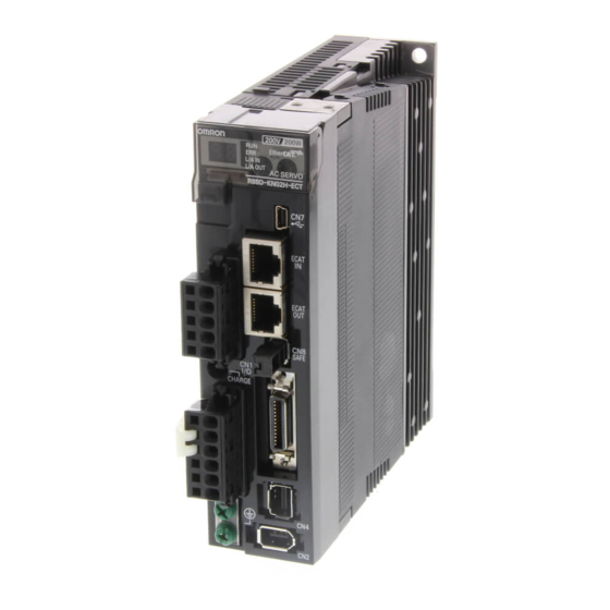
1 Features and System Configuration Names and Functions This section describes the names and functions of Servo Drive parts. 1-3-1 Servo Drive Part Names The Servo Drive part names are given below. EtherCAT status indicators Seven-segment display Analog monitor connector Rotary switches for (CN5) node address setting... -
Page 39: Servo Drive Functions
1 Features and System Configuration 1-3-2 Servo Drive Functions The functions of each part are described below. Display A 2-digit 7-segment display shows the node address, error codes, and other Servo Drive status. Charge Lamp Lights when the main circuit power supply is turned ON. EtherCAT Status Indicators These indicators show the status of EtherCAT communications. -
Page 40: System Block Diagram
1 Features and System Configuration System Block Diagram This is the block diagram of the G5-series AC Servo Drive with Built-in EtherCAT Communications, Linear Motor Type. R88D-KN01L-ECT-L/-KN02L-ECT-L R88D-KN01H-ECT-L/-KN02H-ECT-L/-KN04H-ECT-L CN B CN A FUSE FUSE Voltage detection FUSE SW power 15 V... - Page 41 1 Features and System Configuration R88D-KN04L-ECT-L/-KN08H-ECT-L/-KN10H-ECT-L/-KN15H-ECT-L CN B CN A FUSE Internal Regeneration Resistor FUSE Voltage detection FUSE SW power 15 V Relay Regeneration Overcurrent Current detection supply main Gate drive drive control detection circuit control 3.3 V Display 2.5 V Internal and setting MPU &...
- Page 42 1 Features and System Configuration R88D-KN06F-ECT-L/-KN10F-ECT-L/-KN15F-ECT-L/-KN20F-ECT-L CN A CN D FUSE Internal Regeneration Resistor FUSE CN B CN C Voltage detection FUSE 24 V DC-DC SW power 15 V Relay Regeneration Overcurrent Current detection Gate drive supply main drive control detection circuit control 3.3 V...
- Page 43 1 Features and System Configuration R88D-KN30F-ECT-L CN A CN D FUSE Internal Regeneration Resistor FUSE CN B CN C Voltage detection FUSE 24 V DC-DC SW power 15 V Relay Regeneration Overcurrent Current detection supply main Gate drive drive control detection circuit control 3.3 V...
-
Page 44: Unit Versions
The unit version of a G5-series Servo Drive is given on the product’s nameplate as shown below. Nameplate location Product Nameplate Unit Version Here, the unit version is 1.1. (R88D-KN01L-ECT-L) 1-5-2 Unit Versions Unit version Supported CX-Drive versions Upgraded content Ver. - Page 45 Models and External Dimensions This section explains the models of Servo Drive, Linear Motors, and peripheral devices, and provides the external dimensions and mounting dimensions. 2-1 Servo System Configuration ........2-2 2-2 How to Read Model Numbers .
-
Page 46: Servo System Configuration
2 Models and External Dimensions Servo System Configuration Support Software Controller Automation Software NJ-series CPU Unit with EtherCAT Port Sysmac Studio DC24V Machine Automation Controller NJ301- /NJ501- CJ-series CPU Unit + Position Control Unit with EtherCAT Interface Support Software Support Software CX-One FA Integrated Tool Package CX-Drive CX-Programmer,... - Page 47 2 Models and External Dimensions AC Servo Drive Linear Motor Iron-core family Motor power signal Motor power cable Motor power cable Supplied by the user Motor Coil Unit: R88L-EC-FW- Magnet Track: R88L-EC-FM- Ironless family EtherCAT communications Motor Coil Unit: R88L-EC-GW- Magnet Track: R88L-EC-GM- External Encoder Cable USB communications...
-
Page 48: How To Read Model Numbers
2 Models and External Dimensions How to Read Model Numbers This section describes how to read and understand the model numbers of Servo Drives and Linear Motors. 2-2-1 Servo Drive The Servo Drive model number tells the Servo Drive type, power supply voltage, etc. R88D-KN01H-ECT-L G5-series Servo Drive Drive Type... -
Page 49: Linear Motor
2 Models and External Dimensions 2-2-2 Linear Motor Two models of Linear Motors are available: iron-core family and ironless family. For each of these models, the model numbers of the Motor Coil Unit and Magnet Track are defined as follows. Iron-core family Motor Coil Uni R88L-EC-FW-0303-ANPC... - Page 50 2 Models and External Dimensions Ironless family Motor Coil Unit R88L-EC-GW-0303-ANPS G5-series Linear Motor Component Type GW: Ironless family Motor Coil Unit Effective Magnet Width 03 : 30 mm 05 : 50 mm 07 : 70 mm Coil Model 03 : 3-coil 06 : 6-coil...
-
Page 51: Model Tables
This section lists the standard models of Servo Drives, Connectors, and peripheral equipment. 2-3-1 Servo Drive Model Table The table below shows the Servo Drive models. Specifications Model Single-phase 100 VAC 100 W R88D-KN01L-ECT-L 200 W R88D-KN02L-ECT-L 400 W R88D-KN04L-ECT-L Single-phase/3-phase 200 VAC 100 W R88D-KN01H-ECT-L... -
Page 52: Servo Drive And Linear Motor Combination Tables
R88D-KN30F-ECT-L Note The maximum operation speed is restricted by the guide mechanism, encoder, and other aspects. If it is 5 m/s or higher, please consult with your OMRON representative. 2 - 8 G5-series Linear Motors/Servo Drives With Built-in EtherCAT Communications... - Page 53 R88D-KN10H-ECT-L Note The maximum operation speed is restricted by the guide mechanism, encoder, and other aspects. If it is 5 m/s or higher, please consult with your OMRON representative. G5-series Linear Motors/Servo Drives With Built-in EtherCAT Communications 2 - 9...
-
Page 54: Cable And Peripheral Device Model Tables
2 Models and External Dimensions 2-3-4 Cable and Peripheral Device Model Tables The following tables show the models of EtherCAT communications cables (recommended) and analog monitor cables, as well as the models of peripheral devices such as External Regeneration Resistors and Reactors. - Page 55 Regeneration process capacity: 70 W, 47 Ω (with 150°C thermal sensor) R88A-RR22047S1 Regeneration process capacity: 180 W, 20 Ω (with 200°C thermal sensor) R88A-RR50020S Reactor Applicable Servo Drives Reactor type Model Number of power phases R88D-KN01L-ECT-L Single-phase input 3G3AX-DL2004 R88D-KN02H-ECT-L 3G3AX-DL2007 R88D-KN04L-ECT-L 3G3AX-DL2015 R88D-KN01H-ECT-L Single-phase input...
-
Page 56: External And Mounting Dimensions
Servo Drive Dimensions The dimensional description starts with a Servo Drive of the smallest capacity, which is followed by the next smallest, and so on. Single-phase 100 VAC: R88D-KN01L-ECT-L (100 W) Single-phase/3-phase 100 VAC: R88D-KN01H-ECT-L/-KN02H-ECT-L (100 to 200 W) Wall Mounting... - Page 57 2 Models and External Dimensions Front Mounting (Using Front Mounting Brackets) External dimensions Mounting dimensions 19.5 Ø5.2 2-M4 Rectangular hole (42)* * Rectangular hole dimensions are reference values. G5-series Linear Motors/Servo Drives With Built-in EtherCAT Communications 2 - 13...
- Page 58 2 Models and External Dimensions Single-phase 100 VAC: R88D-KN02L-ECT-L (200 W) Single-phase/3-phase 200 VAC: R88D-KN04H-ECT-L (400 W) Wall Mounting External dimensions Mounting dimensions 2-M4 Front Mounting (Using Front Mounting Brackets) External dimensions Mounting dimensions 19.5 2-M4 Ø5.2 Rectangular hole R2.6 (57)* * Rectangular hole dimensions are reference values.
- Page 59 2 Models and External Dimensions Single-phase 100 VAC: R88D-KN04L-ECT-L (400 W) Single-phase/3-phase 200 VAC: R88D-KN08H-ECT-L (750 W) Wall Mounting External dimensions Mounting dimensions 2-M4 Front Mounting (Using Front Mounting Brackets) External dimensions Mounting dimensions 19.5 2-M4 Ø5.2 Rectangular hole R2.6 (67)* * Rectangular hole dimensions are reference values.
- Page 60 2 Models and External Dimensions Single-phase/3-phase 200 VAC: R88D-KN10H-ECT-L/-KN15H-ECT-L (1 to 1.5 kW) Wall Mounting External dimensions Mounting dimensions 2-M4 Front Mounting (Using Front Mounting Brackets) External dimensions Mounting dimensions 19.5 4-M4 Ø5.2 Ø5.2 Rectangular hole R2.6 R2.6 (88)* * Rectangular hole dimensions are reference values. 2 - 16 G5-series Linear Motors/Servo Drives With Built-in EtherCAT Communications...
- Page 61 2 Models and External Dimensions 3-phase 400 VAC: R88D-KN06F-ECT-L/-KN10F-ECT-L/ -KN15F-ECT-L (600 W to 1.5 kW) Wall Mounting External dimensions Mounting dimensions 2-M4 14.5 Front Mounting (Using Front Mounting Brackets) External dimensions Mounting dimensions 19.5 4-M4 Ø Ø Rectangular hole R2.6 (94)* * Rectangular hole dimensions are reference values.
- Page 62 2 Models and External Dimensions 3-phase 400 VAC: R88D-KN20F-ECT-L (2 kW) Wall Mounting External dimensions Mounting dimensions 17.5 Ø 42.5 6-M4 R2.6 R2.6 26.5 Ø 17.5 Front Mounting (Using Front Mounting Brackets) External dimensions Mounting dimensions 17.5 Ø 42.5 30.7 6-M4 Rectangular hole...
- Page 63 2 Models and External Dimensions 3-phase 400 VAC: R88D-KN30F-ECT-L (3 kW) Wall Mounting External dimensions Mounting dimensions 6-M4 Ø R2.6 R2.6 Ø Front Mounting (Using Front Mounting Brackets) External dimensions Mounting dimensions 6-M4 Ø 40.7 Rectangular hole R2.6 R2.6 (132)* Ø...
-
Page 64: Linear Motor Dimensions
2 Models and External Dimensions 2-4-2 Linear Motor Dimensions Iron-core Motors R88L-EC-FW-0303/-0306 Motor Coil Unit N-M4, effective thread depth 5 450 min. +0.1 -0.2 *1 These values indicate mounting dimensions. Enlarged view of portion A Model L1 [mm] Number of holes [N] Mass [kg] R88L-EC-FW-0303... - Page 65 2 Models and External Dimensions Magnet Track 5 Depth 4 Ø 27.5 (20.5) *3 Use M5 low head allen head bolts. Enlarged view of portion B Number of Model Mass [kg] Depth [mm] [mm] holes [N] R88L-EC-FM-03096-A Approx. 0.22 R88L-EC-FM-03144-A Approx.
- Page 66 2 Models and External Dimensions Magnet Track Enlarged view of portion B Depth 5 Depth 4 Ø (21) *3 Use M5 low head allen head bolts. Model L2 [mm] L3 [mm] Number of holes [N] Mass [kg] R88L-EC-FM-06192-A Approx. 0.77 R88L-EC-FM-06288-A Approx.
- Page 67 2 Models and External Dimensions Magnet Track Enlarged view of portion B Depth 5 Depth 8 Ø 12.2 (22) *3 Use M5 low head allen head bolts. Model L2 [mm] L3 [mm] Number of holes [N] Mass [kg] R88L-EC-FM-11192-A Approx. 2.12 R88L-EC-FM-11288-A Approx.
- Page 68 2 Models and External Dimensions Ironless Motors R88L-EC-GW-0303/-0306/-0309 Motor Coil Unit Ø Model L1 [mm] L2 [mm] Number of holes [N] Mass [kg] R88L-EC-GW-0303 R88L-EC-GW-0306 0.28 R88L-EC-GW-0309 0.36 *1 The weight of a 950-mm cableis included. Magnet Track Ø Model L3 [mm] L4 [mm] Number of holes [N]...
- Page 69 2 Models and External Dimensions R88L-EC-GW-0503/-0506/-0509 Motor Coil Unit 950 min. Ø Model L1 [mm] L2 [mm] Number of holes [N] Mass [kg] R88L-EC-GW-0503 0.48 R88L-EC-GW-0506 0.71 R88L-EC-GW-0509 0.94 *1 The weight of a 950-mm cableis included. Magnet Track 28.4 Ø...
- Page 70 2 Models and External Dimensions R88L-EC-GW-0703/-0706/-0709 Motor Coil Unit 950 min. Ø Model L1 [mm] L2 [mm] Number of holes [N] Mass [kg] R88L-EC-GW-0703 R88L-EC-GW-0706 1.32 R88L-EC-GW-0709 1.74 *1 The weight of a 950-mm cableis included. Magnet Track Ø 28.5 Model L3 [mm] L4 [mm]...
-
Page 71: External Regeneration Resistor Dimensions
2 Models and External Dimensions 2-4-3 External Regeneration Resistor Dimensions R88A-RR08050S/-RR080100S Thermal switch output t1.2 R88A-RR22047S1 Thermal switch output t1.2 R88A-RR50020S G5-series Linear Motors/Servo Drives With Built-in EtherCAT Communications 2 - 27... -
Page 72: Reactor Dimensions
2 Models and External Dimensions 2-4-4 Reactor Dimensions 3G3AX-DL2002 2-M4 Ground terminal (M4) 4-5.2 × 8 3G3AX-DL2004 2-M4 Ground terminal (M4) 4-5.2 × 8 2 - 28 G5-series Linear Motors/Servo Drives With Built-in EtherCAT Communications... - Page 73 2 Models and External Dimensions 3G3AX-DL2007 2-M4 Ground terminal (M4) 4-5.2 × 8 3G3AX-DL2015 2-M4 Ground terminal (M4) 4-5.2 × 8 G5-series Linear Motors/Servo Drives With Built-in EtherCAT Communications 2 - 29...
- Page 74 2 Models and External Dimensions 3G3AX-DL2022 2-M4 Ground terminal (M4) 4-6 × 9 3G3AX-AL2025/-AL2055/-AL4025/-AL4055/-AL2055 Ground terminal (M5) Terminal screw 6- Ø Terminal block Ro R So S To T Ro R So S To Connection Diagram Ø 50±1 Y±1 (Cutout) Dimensions [mm] Model 3G3AX-AL2025...
-
Page 75: Mounting Bracket Dimensions
2 Models and External Dimensions 3G3AX-AL2110/-AL2220/-AL4110/-AL4220 Terminal hole 6- Ø Ro R So S To T R So S To Connection Diagram X±1 Y±1 Ø W = Terminal width (Cutout) Ground terminal (M6) Dimensions [mm] Model 3G3AX-AL2110 3G3AX-AL2220 16.5 3G3AX-AL4110 12.5 3G3AX-AL4220 2-4-5... - Page 76 2 Models and External Dimensions R88A-TK02K Mounting bracket for top side Mounting bracket for bottom side 2-M4 countersunk 2-M4 countersunk 18±0.2 5 18±0.2 R88A-TK03K Mounting bracket for top side Mounting bracket for bottom side 2-M4 countersunk 2-M4 countersunk 30±0.2 30±0.2 R88A-TK04K Mounting bracket for top side Mounting bracket for bottom side...
- Page 77 Specifications This section provides the general specifications, characteristics, connector specifications, I/O circuits of the Servo Drives and Linear Motors, as well as specifications of other peripheral devices. 3-1 Servo Drive Specifications ........3-2 3-1-1 General Specifications .
-
Page 78: Servo Drive Specifications
3 Specifications Servo Drive Specifications Select a Servo Drive that matches the Linear Motor to be used. 3-1-1 General Specifications Item Specifications Operating ambient 0 to 55°C, 20% to 85% max. (with no condensation) temperature and humidity Storage ambient –20 to 65°C, 20% to 85% max. (with no condensation) temperature and humidity Operating and storage No corrosive gases... -
Page 79: Characteristics
3 Specifications 3-1-2 Characteristics 100-VAC Input Models Item R88D-KN01L-ECT-L R88D-KN02L-ECT-L R88D-KN04L-ECT-L Input power supply Main circuit Power supply capacity 0.4 kVA 0.5 kVA 0.9 kVA Power supply voltage Single-phase 100 to 120 VAC (85 to 132 VAC) 50/60 Hz Rated current 2.6 A... - Page 80 3 Specifications 400-VAC Input Models Item R88D-KN06F-ECT-L R88D-KN10F-ECT-L R88D-KN15F-ECT-L Input power supply Main circuit Power supply capacity 1.2 kVA 1.8 kVA 2.3 kVA Power supply voltage 3-phase 380 to 480 VAC (323 to 528 VAC) 50/60 Hz Rated current 2.1 A 2.8 A 3.9 A 32.2 W...
-
Page 81: Ethercat Communications Specifications
3 Specifications 3-1-3 EtherCAT Communications Specifications Item Specifications Communications standard IEC 61158 Type 12, IEC 61800-7 CiA 402 Drive Profile Physical layer 100BASE-TX (IEEE802.3) Connectors RJ45 × 2 (shielded) ECAT IN: EtherCAT input ECAT OUT: EtherCAT output Communications media Ethernet Category 5 (100BASE-TX) or higher (twisted-pair cable with double, aluminum tape and braided shielding) is recommended. -
Page 82: Control I/O Specifications (Cn1)
3 Specifications 3-1-5 Control I/O Specifications (CN1) For the control I/O signal cable, use a shielded twisted-pair cable with 0.18 mm or thicker core wires. The cable length must be 3 m or less. Control I/O Signal Connections and External Signal Processing 12 to 24 VDC +24VIN 4.7 kΩ... - Page 83 3 Specifications Control I/O Signal Tables CN1 Control Inputs Signal Pin No. Symbol Function and interface Name Default +24 VIN Power supply input 12 to 24 VDC The positive input terminal of the external power supply (12 to 24 VDC) for sequence inputs General-purpose Immediate Stop...
-
Page 84: Control Input Circuits
4 The functions that are allocated by default are given in parentheses ( ). Refer to 7-1 Sequence I/O Signals on page 7-2 for the allocations. Connectors for CN1 (Pin 26) Name Model Manufacturer OMRON model number Plug 10126-3000PE Sumitomo 3M R88A-CNW01C Cable Case... -
Page 85: Control Input Details
3 Specifications 3-1-7 Control Input Details This is the detailed information about the CN1 connector input pins. General-purpose Inputs (IN1 to IN8) Pin 5 : General-purpose Input 1 (IN1) - [Immediate Stop Input (STOP)] Pin 7 : General-purpose Input 2 (IN2) - [Positive Drive Prohibition Input (POT)] Pin 8 : General-purpose Input 3 (IN3) - [Negative Drive Prohibition Input (NOT)] Pin 9... - Page 86 3 Specifications Positive Drive Prohibition Input (POT) / Negative Drive Prohibition Input (NOT) • These two signals are the inputs to prohibit positive or negative drive (over-travel inputs). • When these terminals are shorted (default setting), the Servo Drive can drive in the specified movement direction.
-
Page 87: Control Output Circuits
3 Specifications External Latch Input Signals (EXT1, EXT2, and EXT3) • These are the external input signals to latch the actual value in the feedback pulse counter. • The encoder position data is obtained when the External Latch Input is turned ON. •... -
Page 88: Control Output Details
3 Specifications 3-1-9 Control Output Details Control Output Sequence The chart below illustrates the timing of the command inputs after the control power supply is turned ON. Input the Servo ON/OFF operation, position, speed, and force commands in the correct timing, as shown in the chart. - Page 89 3 Specifications *7 The Magnetic Pole Position Estimation Command Time changes with the servo parameter object settings. Make sure that the magnetic pole position estimation completion output flag is turned “ON” before executing the command. If magnetic pole position estimation is not completed successfully, the magnetic pole position estimation completion flag will not turn “ON.”...
- Page 90 3 Specifications Motor Speed Detection Output (TGON) • This output turns ON when the motor speed exceeds the value set by the Speed for Motor Detection (3436 hex). • The output is effective both in positive and negative directions regardless the direction in which the motor moves.
- Page 91 3 Specifications Speed Conformity Output (VCMP) • This output turns ON when the motor speed falls into the range set in the Speed Conformity Detection Range (3435 hex). • It is determined to be conforming when the difference between the commanded speed before acceleration or deceleration process inside the Drive and the motor speed is within the set range of Speed Conformity Detection Range (3435 hex).
-
Page 92: External Encoder Specifications
*1 Set the number of pulses per magnetic pole pitch (or one cycle of electrical angle) to at least 2,048 pulses. *2 OMRON checked the connection of these products in serial communications by using each representative model. Although the connection is confirmed, it does not mean that the functions and performance are guaranteed in the resolution, model, and all aspects of an external encoder. -
Page 93: External Encoder Connector Specifications (Cn4)
*1 Connect external encoder signals to the serial interface (+EXS/–EXS) or 90° phase difference inputs according to the encoder type. Connectors for CN4 (10 Pins) Name Model Manufacturer OMRON model number MUF Connector MUF-PK10K-X J.S.T. Mfg. Co., Ltd. R88A-CNK41L G5-series Linear Motors/Servo Drives With Built-in EtherCAT Communications... - Page 94 3 Specifications Connection of External Encoder Input Signals and Processing of External Signals External encoder power supply output 5.0 V ±5% 250 mA max. 680 Ω +EXS 120 Ω –EXS Serial signal 680 Ω 20 kΩ +EXA 2 kΩ Puls Phase A 120 Ω...
- Page 95 3 Specifications Example of Connection with External Encoder 90° Phase Difference Output (3323 hex = 0) Servo Drive side (CN4) External encoder side 5.0 V ±5% 250 mA max. Power supply area 20 kΩ 2 kΩ +EXA Puls Phase A 120 Ω...
- Page 96 3 Specifications Serial Communications, Absolute Type External Encoder (3323 hex = 2) Absolute Linear Scale by Mitutoyo Corporation Servo Drive side (CN4) AT573A/ST770A/ST770AL E0V 2 680 Ω RQ/DT +EXS 120 Ω RQ/DT –EXS Serial signal 680 Ω Shell Shell Magnescale by Magnescale Co., Ltd Servo Drive side (CN4) Scale Unit SR77/SR87 E0V 2...
-
Page 97: Analog Monitor Connector Specifications (Cn5)
3 Specifications 3-1-12 Analog Monitor Connector Specifications (CN5) Monitor Output Signal Table Monitor Output (CN5) Pin No. Symbol Name Function and interface Analog monitor output 1 Outputs the analog signal for the monitor. Default setting: Motor speed 1 V/(500 mm/s) You can use objects 3416 hex and 3417 hex to change the item and unit. -
Page 98: Usb Connector Specifications (Cn7)
3 Specifications 3-1-13 USB Connector Specifications (CN7) Through the USB connection with computer, operations such as parameter setting and changing, monitoring of control status, checking error status and error history, and parameter saving and loading can be performed. Pin No. Symbol Name Function and interface... - Page 99 A monitor signal is output to detect a safety function failure. EDM+ Shell Frame ground Connected to the ground terminal inside the Servo Drive. Connector for CN8 (8 pins) OMRON model Name Model Manufacturer number Industrial Mini I/O Connector 2013595-1...
- Page 100 3 Specifications EDM Output Circuit Servo Drive External power supply 8 +EDM 12 to 24 VDC Maximum service voltage : 30 VDC or less 7 –EDM Maximum output current : 50 mA max. Leakage current Di: Surge voltage prevention diode : 0.1 mA max.
-
Page 101: Overload Characteristics (Electronic Thermal Function)
3 Specifications Overload Characteristics (Electronic Thermal Function) An overload protection function (electronic thermal) is built into the Servo Drive to protect the drive and Linear Motor from overloading. An overload error will occur according to the timing characteristic if the feedback value for the force command exceeds the overload level. - Page 102 3 Specifications When Overload Detection Level Setting is 100% Time [s] 1,000 3929 hex=0 3929 hex=1 3929 hex=2 3929 hex=3 3929 hex=4 3929 hex=5 3929 hex=6 3929 hex=5, 6 3929 hex=7 Force [%] When Overload Detection Level Setting is 115% Time [s] 1,000 3929 hex=0...
- Page 103 3 Specifications If a constant force command is continuously applied after a period of time equivalent to 3 or more times the overload time constant with the force command value set to 0, the overload time t [s] will be: t [s] = –Overload time constant [s] x log (1 –...
-
Page 104: Linear Motor Specifications
3 Specifications Linear Motor Specifications Two types of Linear Motors are available: Iron-core and Ironless Linear Motors. These Linear Motors consist of one Motor Coil Unit and two or more Magnet Track. The Motor Coil Unit has built-in temperature sensors. Choose an appropriate Linear Motor model based on the load and the operating characteristics. -
Page 105: Performance Specifications Of Iron-Core Linear Motors
3 Specifications 3-3-2 Performance Specifications of Iron-core Linear Motors The following tables show the performance specifications of various iron-core Linear Motor models. R88L-EC-FW-0303/-0306 0303 0306 Motor Coil Unit (R88L-EC-FW- -ANPC) Servo Drives (R88D- -ECT-L) KN01L KN02H KN06F KN02L KN04H KN10F Applicable Servo Drives input voltage 100 VAC 200 VAC 400 VAC 100 VAC 200 VAC 400 VAC Maximum speed (100 VAC) - Page 106 3 Specifications R88L-EC-FW-0606/-0609/-0612 Motor Coil Unit (R88L-EC-FW- -ANPC) 0606 0609 0612 Servo Drives (R88D- -ECT-L) KN04L KN08H KN15F KN10H KN20F KN15H KN30F Applicable Servo Drives input 100 VAC 200 VAC 400 VAC 200 VAC 400 VAC 200 VAC 400 VAC voltage Maximum speed (100 VAC) –...
- Page 107 3 Specifications R88L-EC-FW-1112/-1115 Motor Coil Unit (R88L-EC-FW- -ANPC) 1112 1115 Servo Drives (R88D- -ECT-L) KN15H KN30F KN15H KN30F Applicable Servo Drives input voltage 200 VAC 400 VAC 200 VAC 400 VAC Maximum speed (100 VAC) – – – – Maximum speed (200 VAC) –...
-
Page 108: Iron-Core Linear Motor Speed - Force Characteristics
The following graphs show the characteristics when the coil temperature of the Motor Coil Unit is 100°C. The maximum operation speed is limited by considering the guide mechanism, encoder, and other aspects. If it is 5 m/s or higher, please consult with your OMRON representative. R88L-EC-FW-0303 100 VAC... - Page 109 3 Specifications R88L-EC-FW-0606 100 VAC 200 VAC 400 VAC Momentary Momentary operation operation range range Momentary operation range Continuous Continuous operation range Continuous operation range operation range R88L-EC-FW-0609 100 VAC 200 VAC 400 VAC Momentary Momentary operation operation range range Momentary operation range...
- Page 110 3 Specifications R88L-EC-FW-1112 100 VAC 200 VAC 400 VAC 1,600 1,600 1,600 Momentary Momentary operation operation range range 1,200 1,200 1,200 Momentary operation range Continuous Continuous operation range operation range Continuous operation range R88L-EC-FW-1115 100 VAC 200 VAC 400 VAC 2,000 2,000 2,000...
-
Page 111: Temperature Sensor Specifications Of Iron-Core Linear Motors
3 Specifications 3-3-4 Temperature Sensor Specifications of Iron-core Linear Motors Each Iron-core Linear Motor has one series-connected PTC thermistor per phase. The thermistor can be used as a switch to stop the motor when the Motor Coil Unit is overheated, by utilizing its characteristic that the resistance increases suddenly at around 110°C. -
Page 112: General Specifications Of Ironless Linear Motors
3 Specifications 3-3-5 General Specifications of Ironless Linear Motors Item Description Operating ambient temperature humidity 0ºC to 40ºC, 20% to 80% (with no condensation) Storage ambient temperature and humidity –20ºC to 65ºC, 85% max. (with no condensation) Operating and storage atmosphere No corrosive gases Vibration resistance Acceleration of 49 m/s... - Page 113 3 Specifications Motor Coil Unit (R88L-EC-GW- -ANPS) 0303 0306 0309 KN01L KN02H KN04L KN08H KN10H Servo Drives (R88D- -ECT-L) Applicable Servo Drives input voltage 100 VAC 200 VAC 100 VAC 200 VAC 200 VAC Maximum continuous power consumption Thermal resistance 1.06 0.71 Thermal time constant...
- Page 114 3 Specifications R88L-EC-GW-0703/-0706/-0709 Motor Coil Unit (R88L-EC-GW- -ANPS) 0703 0706 0709 Servo Drives (R88D- -ECT-L) KN02L KN04H KN04L KN08H KN10H Applicable Servo Drives input voltage 100 VAC 200 VAC 100 VAC 200 VAC 200 VAC Maximum speed (100 VAC) – –...
-
Page 115: Ironless Linear Motor Speed - Force Characteristics
3-3-7 Ironless Linear Motor Speed - Force Characteristics The maximum operation speed is limited by considering the guide mechanism, encoder, and other aspects. If it is 5 m/s or higher, please consult with your OMRON representative. R88L-EC-GW-0303 100 VAC 200 VAC... - Page 116 3 Specifications R88L-EC-GW-0309 100 VAC 200 VAC Momentary operation range Momentary operation range Continuous Continuous operation range operation range R88L-EC-GW-0503 100 VAC 200 VAC Momentary Momentary operation range operation range Continuous Continuous operation range operation range 3 - 40 G5-series Linear Motors/Servo Drives With Built-in EtherCAT Communications...
- Page 117 3 Specifications R88L-EC-GW-0506 100 VAC 200 VAC Momentary operation Momentary range operation range Continuous Continuous operation range operation range R88L-EC-GW-0509 100 VAC 200 VAC Momentary Momentary operation operation range range Continuous Continuous operation range operation range G5-series Linear Motors/Servo Drives With Built-in EtherCAT Communications 3 - 41...
- Page 118 3 Specifications R88L-EC-GW-0703 100 VAC 200 VAC Momentary operation range Momentary operation range Continuous Continuous operation operation range range R88L-EC-GW-0706 100 VAC 200 VAC 1,000 1,000 Momentary operation range Momentary operation range Continuous Continuous operation range operation range 3 - 42 G5-series Linear Motors/Servo Drives With Built-in EtherCAT Communications...
- Page 119 3 Specifications R88L-EC-GW-0709 100 VAC 200 VAC 2,000 2,000 Momentary operation range 1,500 1,500 1,000 1,000 Momentary operation range Continuous Continuous operation range operation range G5-series Linear Motors/Servo Drives With Built-in EtherCAT Communications 3 - 43...
-
Page 120: Temperature Sensor Specifications Of Ironless Linear Motors
3 Specifications 3-3-8 Temperature Sensor Specifications of Ironless Linear Motors Ironless Linear Motors have one PTC thermistor in its Motor Coil Unit. This PTC thermistor has a characteristic that the resistance increases suddenly at around 110 º Utilize this characteristic to build a circuit to stop the motor in case of overheating. Be sure to build a circuit that detects overheating at a resistance at around 90 C to 100 C, so that the... -
Page 121: Cable Specifications
3 Specifications 3-3-9 Cable Specifications The following cables come out from iron-core/ironless family Motor Coil Units. Iron-core Family Motor Coil Unit (R88L-EC-FW- -ANPC) The cable length is 450 mm or more. Power Cable Wire color Signal name Black (1ONE) Black (2TWO) Black (3THREE) Green/Yellow Temperature Sensor Cable... -
Page 122: Cable And Connector Specifications
3 Specifications Cable and Connector Specifications The specifications of the cables to connect Servo Drives are shown below. The information on the cable types are also provided. 3-4-1 Resistance to Bending of Robot Cable If the cable is used at a moving part, use a robot cable. Regarding the bending life of a robot cable, a wire rod with a durability of more than 20 million times of use at or above the minimum bending radius is used under the conditions below. -
Page 123: External Encoder Cable Specifications
Cable: 0.65 mm × 3P UL20276 -EXA +EXB -EXB +EXZ -EXZ Shell [Servo Drive side connector] Connector plug model • MUF-PK10K-X (J.S.T. Mfg. Co., Ltd.) • OMRON model: R88A-CNK41L G5-series Linear Motors/Servo Drives With Built-in EtherCAT Communications 3 - 47... -
Page 124: Connector Specifications
3 Specifications 3-4-3 Connector Specifications This section describes the specifications of the control I/O connector, power cable connector, external encoder connector, and safety I/O signal connector. Control I/O Connector (R88A-CNW01C) This is the connector to be connected to the drive’s control I/O connector (CN1). Use this connector when preparing a control cable by yourself. -
Page 125: Ethercat Communications Cable Specifications
AWG22 x 2P Kuramo Electric Co. KETH-PSB-OMR *1 It is recommended that you use this cable in combination with the OMRON XS6G-T421-1 connector. Precautions for Correct Use Precautions for Correct Use The maximum length between nodes is 100 m. However, some cables are specified for less than 100 m. - Page 126 MPS588 Panduit Corporation Japan Branch Osaka Sales Office AWG22 x 2P OMRON Corporation OMRON Corporation Customer XS6G-T421-1 Support *1 It is recommended that you use this connector in combination with the Kuramo Electric Co. KETH-PSB-OMR cable. Precautions for Correct Use Precautions for Correct Use When selecting a connector, confirm that is applicable to the cable that will be used.
- Page 127 3 Specifications Wiring This example shows how to connect a CJ1W-NC281/NC481/NC881/NCF81/NC482/NC882/NCF82 Position Control Unit to Servo Drives using EtherCAT Communications Cables. Connect the EtherCAT master to the ECAT IN connector on the first Servo Drive. Connect the ECAT OUT connector on the first Servo Drive to the ECAT IN connector on the next Servo Drive. Do not connect the ECAT OUT connector on the last Servo Drive.
-
Page 128: Analog Monitor Cable Specifications
3 Specifications 3-4-5 Analog Monitor Cable Specifications Analog Monitor Cable (R88A-CMK001S) Connection Configuration and External Dimensions Symbol White Black Cable: AWG24×3C UL1007 Connector housing: 51004-0600 (Molex Japan) Connector terminal: 50011-8000 (Molex Japan) 3 - 52 G5-series Linear Motors/Servo Drives With Built-in EtherCAT Communications... -
Page 129: Control Cable Specifications
Connector case: EXT3 EXT3 10326-52A0-008 (Sumitomo 3M) EXT2 EXT2 EXT1 EXT1 Terminal Block Connector BATGND BATGND Connector socket: XG4M-2030 (OMRON) BKIRCOM BKIRCOM Strain relief: XG4T-2004 (OMRON) BKIR BKIR ALMCOM ALMCOM Cable Shell AWG28 × 3P + AWG28 × 8C UL2464 * Before you use the Servo Drive, confirm that the signals of Servo Drive connector are set as shown above. - Page 130 3 Specifications Connector-Terminal Block Conversion Unit (XW2B-20G ) The Unit is used with a Connector Terminal Block Cable (Model: XW2Z- J-B34). They convert the control input signal (CN1) of the G5-series Servo Drive into a terminal block. Terminal Block Models Model Description XW2B-20G4...
- Page 131 3 Specifications XW2B-20G5 Dimensions Flat cable connector (MIL type plug) 112.5 Ø Terminal block Note The pitch of terminals is 8.5 mm. Precautions for Correct Use Precautions for Correct Use • When using crimp terminals, use crimp terminals with the following dimensions. Round terminal Fork terminal 3.7 mm...
- Page 132 3 Specifications XW2D-20G6 Dimensions (39.1) 17.6 Ø Precautions for Correct Use Precautions for Correct Use • When using crimp terminals, use crimp terminals with the following dimensions. Round terminal Fork terminal 3.2 mm Ø 5.8 mm max. 3.2 mm 5.8 mm max. Applicable crimp terminals Applicable wires 1.25 to 3...
- Page 133 3 Specifications Terminal Block Wiring Example The example is for the XW2B-20G4, XW2B-20G5, and XW2D-20G6. +24V +24V +24V STOP EXT3 EXT1 BKIR EXT2 BKIRCOM ALMCOM 24 VDC 24 VDC *1 Assign the brake interlock output (BKIR) to pin CN1-1. *2 The XB contact is used to turn ON/OFF the electromagnetic brake. G5-series Linear Motors/Servo Drives With Built-in EtherCAT Communications 3 - 57...
-
Page 134: External Regeneration Resistor Specifications
3 Specifications External Regeneration Resistor Specifications Five types of External Regeneration Resistors are available, as shown in the table below. For how to calculate the amount of regeneration, refer to 4-5 Regenerative Energy Absorption on page 4-47. Regeneration Resistance Nominal absorption for Heat radiation Thermal switch output... -
Page 135: Reactor Specifications
Select an appropriate Reactor for your Servo Drive model. Servo Drives Reactor Number of power Rated Model Model Inductance Mass phases current R88D-KN01L-ECT-L 3G3AX-DL2004 3.2A 10.7 mH Approx. 1.0 kg R88D-KN02L-ECT-L Single-phase input 3G3AX-DL2007 6.1A 6.75 mH Approx. 1.3 kg... - Page 136 3 Specifications 3 - 60 G5-series Linear Motors/Servo Drives With Built-in EtherCAT Communications...
- Page 137 System Design This section explains the installation conditions, wiring methods which include wiring conforming to EMC directives, and regenerative energy calculation methods for the Servo Drive and Linear Motor, and also describes the performance of External Regeneration Resistors. 4-1 Installation Conditions ......... 4-2 4-1-1 Installation Conditions .
-
Page 138: Installation Conditions
4 System Design Installation Conditions This section describes the installation conditions for the Servo Drive and Linear Motor. 4-1-1 Installation Conditions Space Conditions around Servo Drives Install the Servo Drives according to the dimensions shown in the following illustration to ensure proper dispersion of heat from inside the drives and convection inside the panel. - Page 139 4 System Design Additional Information For Drives of 100 V or 200 V with a capacity of 750 W max., the specifications for operating ambient temperature depend on the Drive (A, B, and C) when the clearance between Drives is 1 mm. Drive A: 0 to 50°C Drive B: 0 to 40°C Drive C: 0 to 45°C...
-
Page 140: Iron-Core Linear Motor Installation Conditions
4 System Design 4-1-2 Iron-core Linear Motor Installation Conditions Before operating the Linear Motor, it is necessary to assemble parts such as the linear guides and the external encoder into the Linear Slider, in addition to the Motor Coil Unit and the Magnet Track. An example of the Linear Slider is shown below. - Page 141 4 System Design Installation and Design Conditions Mechanical Tolerance Design and install a Linear Motor system that meets the following requirements. Item Tolerance Flatness of Motor Coil Unit mounting surface 0.1 mm across the entire length of Motor Coil Unit Flatness of Magnet Track mounting surface 0.1 mm/m Accumulative pitch error of Magnet Track mounting screws...
- Page 142 4 System Design • Provide appropriate ventilation as required to prevent excessive rise of the ambient temperature since the heat is dissipated into the air. • If the rise of the ambient temperature must be suppressed for a certain application, or if the moving table dimensions are small, calibrate the cooling system separately to cool the Motor Coil Unit.
- Page 143 4 System Design Fix the first Magnet Track unit with bolts. Install the second Magnet Track unit. Place the second Magnet Track unit in a place where no magnetic attraction force is exerted with the first Magnet Track unit. Slide the second Magnet Track unit while pushing it onto the mounting surface to prevent it from coming off the surface.
- Page 144 4 System Design Move the Motor Coil Unit and the moving table. Remove the protective plate from each installed Magnet Track unit and move the moving table to a position above the Magnet Track. Be aware that, at this time, a magnetic attraction force is exerted between the Motor Coil Unit and the Magnet Track.
- Page 145 4 System Design Direction Adjustment Turn OFF the main circuit power supply and remove the motor cable from the Servo Drive. This is done easily by disconnecting the connector. Turn ON the control power supply. Be sure to check and set the drive direction parameter on the CX-Drive’s Linear Encoder Settings screen.
-
Page 146: Ironless Linear Motor Installation Conditions
4 System Design 4-1-3 Ironless Linear Motor Installation Conditions Before operating the Linear Motor, it is necessary to assemble parts such as the linear guides and the external encoder into the Linear Slider, in addition to the Motor Coil Unit and the Magnet Track. An example of the Linear Slider is shown below. - Page 147 4 System Design Cooling of Motor Coil Unit • The Motor Coil Unit becomes hot during operation. For the Motor Coil Unit, install a moving table (radiator plate) of the recommended dimensions or larger to provide sufficient heat dissipation into the air.
- Page 148 4 System Design Installation Procedure For the installation of ironless linear sliders, no particular order of assembly is specified. In an ironless Linear Motor, no magnetic attraction force is exerted between the Magnet Track and the Motor Coil Unit. However, a strong magnetic attraction force is present between the Magnet Track units. Be careful so that you are not caught or the magnets are damaged by shock.
- Page 149 4 System Design Direction Adjustment Turn OFF the main circuit power supply and remove the motor cable from the Servo Drive. This is done easily by disconnecting the connector. Turn ON the control power supply. Be sure to check and set the drive direction parameter on the CX-Drive's Linear Encoder Settings screen.
-
Page 150: Wiring
*2. Do not use shielded cables for power cables. General-purpose External sensor, etc. *3. Recommended relay: MY relay by OMRON (24 VDC 2A) inputs 1 to 8 Select one that matches the ratings of the brake etc. to be used. - Page 151 External sensor, etc. inputs 1 to 8 Wiring Confirming to EMC Directives. *2. Do not use shielded cables for power cables. *3. Recommended relay: MY relay by OMRON (24 VDC 2A) 24 VDC OUTM1 Select one that matches the ratings of the (BKIR) brake etc.
- Page 152 External sensor, etc. Wiring Confirming to EMC Directives. inputs 1 to 8 *2. Do not use shielded cables for power cables. *3. Recommended relay: MY relay by OMRON (24 VDC 2A) OUTM1 24 VDC Select one that matches the ratings of the (BKIR) brake etc.
- Page 153 General-purpose External sensor, etc. *2. Do not use shielded cables for power cables. inputs 1 to 8 *3. Recommended relay: MY relay by OMRON (24 VDC 2A) Select one that matches the ratings of the 24 VDC brake etc. to be used.
-
Page 154: Main Circuit And Linear Motor Connections
4 System Design 4-2-2 Main Circuit and Linear Motor Connections When wiring the main circuit, use proper wire sizes, grounding systems, and noise resistance. R88D-KN01L-ECT-L/-KN02L-ECT-L R88D-KN01H-ECT-L/-KN02H-ECT-L/-KN04H-ECT-L Main Circuit Connector Specifications (CNA) Symbol Name Function Main circuit power R88D-KN L-ECT-L (100 to 200 W): Single-phase 100 to 120 VAC (85 to 132 VAC) - Page 155 4 System Design R88D-KN04L-ECT-L R88D-KN08H-ECT-L/-KN10H-ECT-L/-KN15H-ECT-L Main Circuit Connector Specifications (CNA) Symbol Name Function Main circuit power R88D-KN L-ECT-L (400 W): Single-phase 100 to 120 VAC (85 to 132 VAC) 50/60 Hz supply input R88D-KN H-ECT-L (750 W to 1.5 kW): Single-phase 200 to 240 VAC (170 to 264 VAC) 50/60 Hz Control circuit R88D-KN L-ECT-L: Single-phase 100 to 120 VAC (85 to 132 VAC) 50/60 Hz...
- Page 156 4 System Design R88D-KN06F-ECT-L/-KN10F-ECT-L/-KN15F-ECT-L/ -KN20F-ECT-L Main Circuit Connector Specifications (CNA) Symbol Name Function Main circuit power 3-phase 380 to 480 VAC (323 to 528 VAC) 50/60 Hz supply input Motor Connector Specifications (CNB) Symbol Name Function Motor connection Phase U These are the output terminals to the Linear Motor.
- Page 157 4 System Design R88D-KN30F-ECT-L Control Circuit Terminal Block Specifications (TB1) Symbol Name Function 24 V Control circuit 24 VDC (20.4 to 27.6 VDC) power supply input Main Circuit Terminal Block Specifications (TB2) Symbol Name Function Main circuit power 3-phase 380 to 480 VAC (323 to 528 VAC) 50/60 Hz supply input External Normally B2 and B3 are shorted.
-
Page 158: Terminal Block Wire Sizes
4 System Design 4-2-3 Terminal Block Wire Sizes This section shows the terminal block wire sizes used for each Servo Drive model. 100-VAC Input Drive Wire Sizes The terminal block wire sizes used for 100-VAC input Servo Drive models are as shown below. Model (R88D-) KN01L-ECT-L KN02L-ECT-L... - Page 159 4 System Design 400-VAC Input Drive Wire Sizes The terminal block wire sizes used for 400-VAC input Servo Drive models are as shown below. Model (R88D-) KN06F-ECT-L KN10F-ECT-L KN15F-ECT-L KN20F-ECT-L KN30F-ECT-L Item Unit Main circuit power Rated current supply input Wire size –...
-
Page 160: Terminal Block Wiring Procedure
4 System Design 4-2-4 Terminal Block Wiring Procedure On a Servo Drive with 2.0 kW or less, connector-type terminal blocks are used. The procedure for wiring these terminal blocks is explained below. Connector-type terminal blocks For example, R88D-KN02H-ECT-L Remove the terminal block from the Servo Drive before wiring. The Servo Drive may be damaged if the wiring is done with the terminal block in place. - Page 161 4 System Design Additional Information The wire may not be inserted easily depending on the shape of the ferrule connected to it. If this occurs, perform one of the following methods before inserting the wire. • Change the direction of inserting the connector by 90º. •...
-
Page 162: Wiring Conforming To Emc Directives
4 System Design Wiring Conforming to EMC Directives G5-series Servo Drives conform to the EMC Directives (EN 55011 Class A Group 1 (EMI) and EN 61000-6-2 (EMS)). EMC-related performance of these products, however, will be influenced by the configuration, wiring, and other conditions of the equipment in which the products are installed. -
Page 163: Vac Input Servo Drive Models
Single-phase 100/200 VAC Co., Ltd. (5 A) 3SUP-HU10-ER-6 3-phase 200 VAC (10 A) 3SUP-HU30-ER-6 3-phase 200 VAC (30 A) 3SUP-HL50-ER-6B 3-phase 200 VAC (50 A) Servo Drive OMRON – Servomotor OMRON – Clamp core ZCAT3035-1330 – Clamp core Konno Industry RJ8035 –... - Page 164 Okaya Electric Industries R·A·V-801BXZ-4 – Co., Ltd. Noise filter Schaffner EMC Inc. FN258L-16-07 3-phase 400 VAC (16 A) FN258L-30-07 3-phase 400 VAC (30 A) Servo Drive OMRON – Servomotor OMRON – Clamp core ZCAT3035-1330 Clamp core Konno Industry RJ8035 Clamp core...
-
Page 165: Noise Reduction
4 System Design Noise Reduction This section provides a wiring example with a G5-series Linear Motor as a means to prevent anticipated noise interference with peripheral equipment when a linear system is installed. 4-4-1 Wiring Method 100-VAC and 200-VAC Input Servo Drive Models Single-phase: 100 VAC 3-phase: 200 VAC... - Page 166 Single-phase Co., Ltd. 100/200 VAC (5 A) 3SUP-HU10-ER-6 3-phase 200 VAC (10 A) 3SUP-HU30-ER-6 3-phase 200 VAC (30 A) 3SUP-HU50-ER-6B 13-phase 200 VAC (50 A) Servo Drive OMRON – Linear Motor – – External encoder – – – Clamp core ZCAT3035-1330 –...
- Page 167 Okaya Electric Industries R·A·V-781BWZ-4 – Co., Ltd. Noise filter Schaffner EMC Inc. FN258L-16-07 3-phase 400 VAC (16 A) FN258L-30-07 3-phase 400 VAC (30 A) Servo Drive OMRON – Linear Motor – – External encoder – – – Clamp core ZCAT3035-1330...
- Page 168 4 System Design Control Panel Structure Openings in the control panel, such as holes for cables, panel mounting holes, and gaps around the door, may allow electromagnetic waves into the panel. To prevent this, observe the recommendations described below when designing or selecting a control panel. Case Structure •...
-
Page 169: Selecting Connection Components
20-ms allowable current that is greater than the total amount of the inrush current in the following table. Inrush current [A0-p] Control Servo Drive model Main circuit circuit power power supply supply R88D-KN01L-ECT-L R88D-KN02L-ECT-L R88D-KN04L-ECT-L R88D-KN01H-ECT-L R88D-KN02H-ECT-L R88D-KN04H-ECT-L R88D-KN08H-ECT-L R88D-KN10H-ECT-L R88D-KN15H-ECT-L... - Page 170 The following table shows the leakage current of each Servo Drive model. Leakage current Servo Drive model Input power supply (Power cable: 3 m) R88D-KN01L-ECT-L Single-phase 100 V 0.6 mA R88D-KN02L-ECT-L Single-phase 100 V 0.6 mA...
- Page 171 4 System Design Surge Absorber • Use surge absorbers to absorb lightning surge voltage and abnormal voltage from power supply input lines. • When selecting surge absorbers, take into account the varistor voltage, the surge immunity and the energy tolerated dose. •...
- Page 172 Noise filter for power supply input Number of Rated Leakage current Model Model Manufacturer power phases current (60 Hz) max. R88D-KN01L-ECT-L Single-phase SUP-EK5-ER-6 1.0 mA (at 250 VAC) input R88D-KN02L-ECT-L Single-phase R88D-KN04L-ECT-L 3SUP-HU10-ER-6 10 A 3.5 mA (at 500 VAC)
- Page 173 4 System Design • Use twisted-pair cables for the power supply cables, or bind the cables. Twisted-pair cables Bound cables Servo Drive Servo Drive Binding External Dimensions SUP-EK5-ER-6 3SUP-HU10-ER-6 100±2.0 53.1±2.0 88.0 75.0 Ground terminal Attachment screw for cover 11.6 13.0 Cover Noise filter...
- Page 174 4 System Design Circuit Diagram SUP-EK5-ER-6 3SUP-HU10-ER-6 3SUP-HU30-ER-6 4 - 38 G5-series Linear Motors/Servo Drives With Built-in EtherCAT Communications...
- Page 175 Use one of the following filters to prevent switching noise of PWM of the Servo Drive and to prevent noise emitted from the internal clock circuit. Model Manufacturer Application OMRON For Drive output and power cable 3G3AX-ZCL1 OMRON For Drive output and power cable...
- Page 176 4 System Design External Dimensions 3G3AX-ZCL1 3G3AX-ZCL2 3-M4 180±2 2-M5 160±2 ESD-R-47B ZCAT3035-1330 17.5 Ø RJ8035/RJ8095 T400-61D Dimensions [unit: mm] Rated Model Core current thickness RJ8035 35 A R3.5 RJ8095 95 A R3.5 4 - 40 G5-series Linear Motors/Servo Drives With Built-in EtherCAT Communications...
- Page 177 4 System Design Impedance Characteristics 3G3AX-ZCL1 3G3AX-ZCL2 1,000 1,000 10,000 Frequency [kHz] Frequency [kHz] ESD-R-47B ZCAT3035-1330 1,000 10,000 1,000 1,000 1,000 Frequency [MHz] Frequency [MHz] RJ8035 RJ8095 10,000 10,000 1,000 1,000 0.01 0.01 1,000 1,000 Frequency [kHz] Frequency [kHz] T400-61D 0.01 0.001 0.0001...
- Page 178 4 System Design Surge Suppressors • Install surge suppressors for loads that have induction coils, such as relays, solenoids, brakes, clutches, etc. The following table shows the types of surge suppressors and recommended products. Type Feature Recommended product Diodes Diodes are used for relatively small loads such Use a fast-recovery diode with a short reverse as relays when the reset time is not a critical recovery time.
- Page 179 4 System Design Improving External Encoder Cable Noise Resistance Take the following steps during wiring and installation to improve the external encoder’s noise resistance. • Always use the specified external encoder cables. • Do not roll cables. If cables are long and are rolled, mutual induction and inductance will increase and cause malfunctions.
- Page 180 Select the proper Reactor model according to the Servo Drive to be used. Servo Drive Reactor Number of power Rated Model Model Inductance phases current R88D-KN01L-ECT-L 3G3AX-DL2004 3.2 A 10.7 mH Single-phase input R88D-KN02L-ECT-L 3G3AX-DL2007 6.1 A 6.75 mH R88D-KN04L-ECT-L 3G3AX-DL2015 9.3 A...
- Page 181 • Select a noise filter with a rated current at least twice the Servo Drive’s continuous output current. The following table shows the noise filters that are recommended for motor output lines. Manufacturer Model Rated current Comment OMRON 3G3AX-NFO01 For inverter output 3G3AX-NFO02 12 A 3G3AX-NFO03...
- Page 182 4 System Design 3G3AX-NFO03/-NFO04/-NFO05/-NFO06 Ø Dimensions [mm] Model 3G3AX-NFO03 – – 3G3AX-NFO04 3G3AX-NFO05 3G3AX-NFO06 4 - 46 G5-series Linear Motors/Servo Drives With Built-in EtherCAT Communications...
-
Page 183: Regenerative Energy Absorption
4 System Design Regenerative Energy Absorption A Servo Drive uses its built-in capacitors to absorb the regenerative energy produced during Linear Motor deceleration. If the amount of regenerative energy is too much for the built-in capacitors to absorb, it also uses an Internal Regeneration Resistor. An overvoltage error occurs, however, if the amount of regenerative energy from the Linear Motor is too large. - Page 184 4 System Design Determining the Capacity of Regenerative Energy Absorption by Built-in Capacitors If both the values Eg1 and Eg2 [J] mentioned above are equal to or less than the value of the Servo Drive’s regenerative energy that can be absorbed by built-in capacitors Ec [J], the Servo Drive can process regenerative energy only by its built-in capacitors.
-
Page 185: Servo Drive Regeneration Absorption Capacity
Allowable resistor Regenerative energy to be minimum Servo Drive model absorbed by built-in Average amount of regeneration capacitor Ec [J] regenerative energy to resistance [Ω] be absorbed [W] R88D-KN01L-ECT-L – R88D-KN02L-ECT-L – R88D-KN04L-ECT-L R88D-KN01H-ECT-L – R88D-KN02H-ECT-L – R88D-KN04H-ECT-L – R88D-KN08H-ECT-L... -
Page 186: Regenerative Energy Absorption With An External Regeneration Resistor
4 System Design 4-5-3 Regenerative Energy Absorption with an External Regeneration Resistor If the regenerative energy exceeds the regeneration absorption capacity of the Servo Drive, connect an External Regeneration Resistor. Connect the External Regeneration Resistor between B1 and B2 terminals on the Servo Drive. Double-check the terminal names when connecting the resistor because the drive may be damaged if connected to the wrong terminals. -
Page 187: Connecting An External Regeneration Resistor
This section describes how to connect an External Regeneration Resistor. Check your Servo Drive model before connecting an External Regeneration Resistor because the connection method varies depending on the Servo Drive. R88D-KN01L-ECT-L/-KN02L-ECT-L/-KN01H-ECT-L/ -KN02H-ECT-L/-KN04H-ECT-L Normally B2 and B3 are open. If an External Regeneration Resistor is necessary, connect the External Regeneration Resistor between B1 and B2 as shown in the diagram below. - Page 188 4 System Design R88D-KN04L-ECT-L/-KN08H-ECT-L/-KN10H-ECT-L/ -KN15H-ECT-L/-KN06F-ECT-L/-KN10F-ECT-L/-KN15F-ECT-L/ -KN20F-ECT-L/-KN30F-ECT-L Normally B2 and B3 are shorted. If an External Regeneration Resistor is necessary, remove the short-circuit bar between B2 and B3, and then connect the External Regeneration Resistor between B1 and B2 as shown in the diagram below.
- Page 189 4 System Design Combining External Regeneration Resistors Regeneration absorption 20 W 40 W 70 W 140 W capacity Model R88A-RR08050S R88A-RR08050S R88A-RR22047S R88A-RR22047S R88A-RR080100S R88A-RR080100S R88A-RR22047S1 R88A-RR22047S1 50 Ω/100 Ω 25 Ω/50 Ω 47 Ω 94 Ω Resistance value Connection method Regeneration absorption...
- Page 190 4 System Design 4 - 54 G5-series Linear Motors/Servo Drives With Built-in EtherCAT Communications...
- Page 191 EtherCAT Communications This section describes EtherCAT communications under the assumption that the G5- series Servo Drive is connected to the Machine Automation Controller NJ-series (Model: NJ301- /NJ501- ) or Position Control Unit (Model: CJ1W-NC281/NC481/NC881/NCF81/NC482/NC882/NCF82). 5-1 Display Area and Settings ........5-2 5-1-1 Node Address Setting .
-
Page 192: Display Area And Settings
5 EtherCAT Communications Display Area and Settings The display area of the G5-series AC Servo Drives With Built-in EtherCAT Communications, Linear Motor Type is as shown below. Status indicators Node address switch □ RUN □ ERR □ L/A IN □ L/A OUT 5-1-1 Node Address Setting The node address switches located in the display area are used to set the EtherCAT node address. -
Page 193: Status Indicators
5 EtherCAT Communications 5-1-2 Status Indicators The following table shows the EtherCAT status indicators and their meaning. Name Color Status Description Green Init state Blinking Pre-Operational state Single flash Safe-Operational state Operational state No error Blinking Communications setting error Single flash Synchronization error or communications data error Double flash Application WDT timeout... -
Page 194: Structure Of The Can Application Protocol Over Ethercat
5 EtherCAT Communications Structure of the CAN Application Protocol over EtherCAT The structure of the CAN application protocol over EtherCAT (CoE) for the G5-series AC Servo Drives With Built-in EtherCAT Communications, Linear Motor Type is described in this section. Servo Drive Application layer Servo Drive application Object dictionary... -
Page 195: Ethercat State Machine
5 EtherCAT Communications EtherCAT State Machine The EtherCAT State Machine (ESM) of the EtherCAT slave is controlled by the EtherCAT Master. Init Pre-Operational Safe-Operational Operational Status Description communications reception transmission Init Not possible Not possible Communications are being initialized. possible Communications are not possible. -
Page 196: Process Data Objects (Pdos)
5 EtherCAT Communications Process Data Objects (PDOs) The process data objects (PDOs) are used to transfer data during cyclic communications in realtime. PDOs can be reception PDOs (RxPDOs), which receive data from the controller, or transmission PDOs (TxPDOs), which send status from the Servo Drive to the host controller RxPDO Operation command, target position, etc. -
Page 197: Sync Manager Pdo Assignment Settings
5 EtherCAT Communications 5-4-2 Sync Manager PDO Assignment Settings A Sync manager channel consists of several PDOs. The Sync manager PDO assignment objects describe how these PDOs are related to the Sync Manager. The number of PDOs is given in sub-index 00 hex of the Sync manager PDO assignment table. In this table, index 1C12 hex is for RxPDOs and 1C13 hex is for TxPDOs. - Page 198 5 EtherCAT Communications PDO Mapping 2 (Position Control, Speed Control, Force Control, and Touch Probe Function) This is the mapping for an application that uses one of the following modes: Cyclic synchronous position mode (csp), Cyclic synchronous velocity mode (csv), and Cyclic synchronous torque mode (cst).
-
Page 199: Variable Pdo Mapping
5 EtherCAT Communications PDO Mapping 5 (Position Control, Speed Control, Touch Probe Function, Force Limit, and Force Feed-forward) This is the mapping for an application that switches between Cyclic synchronous position mode (csp) and Cyclic synchronous velocity mode (csv). Touch probe function and force limit can be used. The force feed-forward amount can be specified by using the Torque offset (60B2 hex). -
Page 200: Multiple Pdo Mapping
5 EtherCAT Communications Maximum Number of Objects and Maximum Total Size Allowed in a PDO Mapping PDO Mapping Object Max. No. of Objects Max. Total Size of Objects RxPDO (1600 hex) 24 bytes TxPDO(1A00 hex) 30 bytes *1 When you assign the PDO mapping other than 1A00 hex simultaneously to TxPDO, total size must be 30 bytes or less. - Page 201 5 EtherCAT Communications Available PDO Mapping Combinations Receive PDO mapping (RxPDO) Transmit PDO mapping (TxPDO) One of the mappings in 1701 to 1705 hex and another • One of the mappings in 1B01 to 1B04 hex and in 1600 hex another in 1A00 hex •...
-
Page 202: Service Data Objects (Sdos)
5 EtherCAT Communications Service Data Objects (SDOs) G5-series Servo Drives support SDO communications. SDO communications are used for setting objects and monitoring the status of G5-series Servo Drives. Objects can be set and the status monitored by reading and writing data to the entries in the object dictionary of the host controller. Abort Codes The following table shows the abort codes for when an SDO communications error occurs. -
Page 203: Synchronization With Distributed Clocks
5 EtherCAT Communications Synchronization with Distributed Clocks A mechanism called a distributed clock (DC) is used to synchronize EtherCAT communications. The DC mode is used for G5-series Servo Drives to perform highly accurate control in a multi-axis system. In DC mode, the master and slaves are synchronized by sharing the same clock. Interruptions (Sync0) are generated in the slaves at precise intervals based on this clock. -
Page 204: Emergency Messages
5 EtherCAT Communications Emergency Messages When an error or warning occurs in a G5-series Servo Drive, an emergency message is sent to the master using mailbox communications. An emergency message is not sent for a communications error. You can select whether to send emergency messages by setting Diagnosis history (10F3 hex). In the default setting, the Diagnosis History object (10F3 hex, Sub: 05 hex (Flags)) is 0 and no emergency message will be sent. -
Page 205: Sysmac Device Features
Sysmac Device Features The control device product designed according to standardized communications and user interface specifications for OMRON control devices are called a Sysmac Device. And the features available with such a Device is called Sysmac Device Features. This section describes the features the G5-series Servo Drive provides when combined with a Machine Automation Controller such as NJ series and automation software. - Page 206 5 EtherCAT Communications Saving the Node Address Setting When the node address switch setting is “00” (Software Setup mode), the node address value you set in Sysmac Studio is enabled. In the Software Setup mode, in Sysmac Studio, execute [Write Slave Node Address] on the [EtherCAT Edit] screen to save the slave node address setting in the nonvolatile memory of the G5- series Servo Drive.
- Page 207 If one of these slaves finds that SII information with which it cannot operate was written, it generates an SII Check Error (Error No. 88.3). If this error persists even after turning OFF and then ON the power again, contact your OMRON sales representative. Precautions for Correct Use Precautions for Correct Use Do not use third-party or any other configuration tools to edit the SII information.
- Page 208 5 EtherCAT Communications 5 - 18 G5-series Linear Motors/Servo Drives With Built-in EtherCAT Communications...
- Page 209 6-5 Homing Mode ..........6-15 6-6 Connecting with OMRON Controllers ......6-16...
-
Page 210: Cyclic Synchronous Position Mode
6 Basic Control Functions Cyclic Synchronous Position Mode In this mode of operation, the controller has a path generation function (an operation profile calculation function) and it gives the target position to the Servo Drive using cyclic synchronization. Position control, speed control, and force control are performed by the Servo Drive. The Velocity offset (60B1 hex) and Torque offset (60B2 hex) can be used as speed feed-forward and force feed-forward amounts. -
Page 211: Related Objects
6 Basic Control Functions 6-1-1 Related Objects Default Index Sub-index Name Access Size Unit Setting range setting 6040 hex 00 hex Controlword – 0 to FFFF hex 0000 hex 6060 hex 00 hex Modes of operation INT8 – 0 to 10 607A hex 00 hex Target position... -
Page 212: Block Diagram For Position Control Mode
6 Basic Control Functions 6-1-2 Block Diagram for Position Control Mode The following block diagram is for position control using an R88D-KN -ECT-L-series Servo Drive. 6062 hex Velocity Motor Velocity 607A hex Motor Velocity Demand Position Demand Value Demand Value Demand Value Target Position Value After Filtering... -
Page 213: Cyclic Synchronous Velocity Mode
6 Basic Control Functions Cyclic Synchronous Velocity Mode In this mode of operation, the controller has a path generation function (an operation profile calculation function) and it gives the target speed to the Servo Drive using cyclic synchronization. Speed control and force control are performed by the Servo Drive. -
Page 214: Related Objects
6 Basic Control Functions 6-2-1 Related Objects Default Index Sub-index Name Access Size Unit Setting range setting 6040 hex 00 hex Controlword – 0 to FFFF hex 0000 hex 6060 hex 00 hex Modes of operation INT8 – 0 to 10 60FF hex 00 hex Target velocity... -
Page 215: Block Diagram For Speed Control Mode
6 Basic Control Functions 6-2-4 Block Diagram for Speed Control Mode The following block diagram is for speed control using an R88D-KN -ECT-L-series Servo Drive. Gain Switching Setting 2 3114 3120 60B2 hex Torque Offset Delay Time 3121 [0.1%] Level 3122 Hysteresis 3123... -
Page 216: Cyclic Synchronous Torque Mode
6 Basic Control Functions Cyclic Synchronous Torque Mode In this mode of operation, the controller has a path generation function (an operation profile calculation function) and it gives the target torque (force) to the Servo Drive using cyclic synchronization. Force control is performed by the Servo Drive. -
Page 217: Related Objects
6 Basic Control Functions 6-3-1 Related Objects Default Index Sub-index Name Access Size Unit Setting range setting 6040 hex 00 hex Controlword – 0 to FFFF hex 0000 hex 6060 hex 00 hex Modes of operation INT8 – 0 to 10 6071 hex 00 hex Target torque... -
Page 218: Related Functions
6 Basic Control Functions 6-3-3 Related Functions Index Name Description Reference 3321 hex Speed Limit Value Setting Set the speed limit value for force control. During force control, P. 9-26 the speed is controlled so as not to exceed the level set by the speed limit value. -
Page 219: Profile Position Mode
6 Basic Control Functions Profile Position Mode In this mode of operation, the controller uses the path generation function (an operation profile calculation function) inside the G5-series Servo Drive to perform PTP positioning operation. It executes path generation, position control, speed control, and torque control based on the target position, profile velocity, profile acceleration, profile deceleration, and other information. -
Page 220: Related Objects
6 Basic Control Functions The following diagram shows the control function configuration of Profile position mode. Position demand value (6062 hex) Limit Position actual value (6064 hex) Function Following error actual value (60F4 hex) Control Velocity actual value (606C hex) Function Following error window (6065 hex) Torque actual value (6077 hex) (=Torque demand) -
Page 221: Description Of Function
6 Basic Control Functions *1 The Following error window object can be set to between 0 and 134,217,728, or 4,294,967,295. If the object is set to 4,294,967,295, the detection of Following error will be disabled. If it is set to 0, a Following error will always occur. -
Page 222: Controlword (6040 Hex) In Profile Position Mode
6 Basic Control Functions The Target value can be changed while PTP positioning is in progress. During PTP positioning, change the Target position (607A hex) or Profile velocity (6081 hex) value. Changing the Controlword (6040 hex) bit 4 (New set-point) from 0 to 1 causes the G5-series Servo Drive to execute positioning with the changed value. -
Page 223: Homing Mode
When performing the homing operation using this procedure, refer to the operating manual for the controller and A-1-6 Homing Mode Specifications on page A-15. Additional Information With the OMRON NJ-series Machine Automation Controllers (Model: NJ301- /NJ501- and the Position Control Units (Model: CJ1W-NC281/NC481/NC881/NCF81/NC482/NC882/NCF82), use Procedure 1. -
Page 224: Connecting With Omron Controllers
6 Basic Control Functions Connecting with OMRON Controllers This section describes the settings required to connect the Servo Drive with an OMRON NJ-series Machine Automation Controller (Model: NJ301- /NJ501- ) and an EtherCAT-compatible Position Control Unit (Model: CJ1W-NC281/NC481/NC881/NCF81/NC482/NC882/NCF82). Related Objects Objects listed in the following table can be used without changing them from their default values. - Page 225 6 Basic Control Functions Position Control Units (CJ1W-NC281/NC481/NC881/NCF81/NC482/NC882/NCF82) Index Sub-index Name Default setting Description 3013 hex 00 hex Force Limit 1 5,000 Default setting is 500.0% 3401 hex 00 hex Input Signal Selection 2 0081 8181 hex Positive Drive Prohibition Input (NC) 3402 hex 00 hex Input Signal Selection 3...
- Page 226 6 Basic Control Functions 6 - 18 G5-series Linear Motors/Servo Drives With Built-in EtherCAT Communications...
- Page 227 Applied Functions This section outlines the applied functions such as the electronic gear and gain switching, and explains the settings. 7-1 Sequence I/O Signals ......... . . 7-2 7-1-1 Input Signals .
-
Page 228: Sequence I/O Signals
7 Applied Functions Sequence I/O Signals You can set sequences in various operating conditions. For the connection of I/O signals and processing of external signals, refer to 3-1-5 Control I/O Specifications (CN1) on page 3-6. 7-1-1 Input Signals You can allocate input signal functions to the input pins of the control I/O connector (CN1). In addition, you can change logic. - Page 229 7 Applied Functions Objects That Can Be Assigned Use the following objects when changing the input signal allocations. For the setting method, refer to Input Signal Allocation Method on page 7-3. Index Name Description Reference 3400 hex Input Signal Selection 1 Set the IN1 input function allocation.
- Page 230 7 Applied Functions Function Number Table The set values to be used for allocations are as follows: Set value Signal name Symbol NO (normally open) contact NC (normally close) contact Disabled – 00 hex Setting not available Positive Drive Prohibition 01 hex 81 hex Input...
-
Page 231: Output Signals
7 Applied Functions 7-1-2 Output Signals You can allocate any of output signal functions to the output pins for the control I/O connector (CN1). In addition, you can change logic. Output Signal Default Setting The allocations of the default output signals are as follows. Refer to Output Signal Allocation Method on page 7-6 to change the allocations. - Page 232 7 Applied Functions Output Signal Allocation Method Input the setting for each control mode to any of the objects from 3410 to 3411 hex to allocate the signals. Set the objects based on hexadecimal in the same manner as for the input signal allocations. Set the set value of the function for each control mode in “...
- Page 233 7 Applied Functions Set value Signal name Symbol Remote Output 1 R-OUT1 10 hex Setting not available Remote Output 2 R-OUT2 11 hex Setting not available Magnetic Pole Position Estimation Completion Output CS-CMP 12 hex Setting not available Precautions for Correct Use Precautions for Correct Use •...
-
Page 234: Positive And Negative Drive Prohibition Functions
7 Applied Functions Positive and Negative Drive Prohibition Functions If the Positive Drive Prohibition Input (POT) or the Negative Drive Prohibition Input (NOT) is opened, the motor will stop moving. You can thus prevent the motor from moving outside of the movement range of the device by using limit inputs from the device connected to the Servo Drive. - Page 235 7 Applied Functions Drive Prohibition Input Selection Description (3504 hex) Positive drive prohibition input and negative drive prohibition input enabled. The operation when a signal is input is as follows. • Positive drive prohibition input shorted: Positive limit switch not operating and status normal.
- Page 236 7 Applied Functions *2 The term “During deceleration” shows the distance until the motor decreases its speed to 30 mm/s or less from the normal operation. Once it decelerates to 30 mm/s or lower speed, the operation conforms to the description for “after stopping,” regardless of the actual speed.
-
Page 237: Overrun Protection
7 Applied Functions Overrun Protection This function detects an Overrun Limit Error (Error No. 34.0) and stops the Linear Motor if the motor exceeds the allowable operating range set for the Overrun Limit Setting (3514 hex) with respect to the position command input. -
Page 238: Operation Example
7 Applied Functions 7-3-3 Operation Example No Position Command Input (Servo ON) No position command is entered. The motor’s allowable operating range is the range set in object 3514 hex on both the right and left. An overrun limit error will occur (Error No. 34.0) if the load enters the error range due to vibration. -
Page 239: Backlash Compensation
7 Applied Functions Backlash Compensation The function compensates for backlash for position control. Additional Information The Servo Drive supports this function although backlash never occurs in a Linear Motor. Objects Requiring Settings Index Name Description Reference 3704 hex Backlash Compensation Select whether to enable or disable backlash P. - Page 240 7 Applied Functions Precautions for Correct Use Precautions for Correct Use • When the mode of operation is switched from the Position Control Mode to the Speed/Force Control Mode, the backlash compensation state is retained as is. Therefore, after returning to the Position Control mode again, you can restart with the backlash compensation state set in the previous Position Control Mode.
-
Page 241: Brake Interlock
It is also possible to use the controller’s function to force the brake control via EtherCAT communications. Additional Information It is not supported on the OMRON Machine Automation Controller NJ-series (Model: NJ301- /NJ501- ) and Position Control Unit (Model: CJ1W-NC 8 ). -
Page 242: Operation Timing
7 Applied Functions 7-5-2 Operation Timing This section shows the timing of the Brake Interlock Output (BKIR). Basic Timing Control Power Supply (L1C, L2C) Servo ON/OFF Servo OFF Servo ON Servo OFF Brake Interlock Output (BKIR) Request to release brake Forced-braking is possible. - Page 243 7 Applied Functions Servo ON/OFF Operation Timing When Motor is Moving Based on these operation timings, regenerative energy is produced if the motor movement stops abnormally. Accordingly, repeated operation cannot be performed. Provide a wait time of at least 10 minutes for the motor to cool down.
- Page 244 7 Applied Functions Operation Timing When an Error Occurs (Servo ON) Error status Normal Error 0.5 to 5 ms Power No power supply Motor Power Supply supply Released Dynamic DB engaged Brake released Engaged Servo Ready READY Output (READY) Error Output Error Normal (/ALM)
- Page 245 7 Applied Functions Operation Timing When Resetting Errors Reset Error Reset Command 16 ms or more READY Servo Ready Output (READY) Error Output Error Normal (/ALM) 0 ms or more Servo ON/OFF Servo OFF Servo ON 2 ms or more Released Dynamic Brake operation...
-
Page 246: Electronic Gear Function
For communications cycles for which the electronic gear is not supported (250 or 500 µs), a Function Setting Error (Error No. 93.4) will occur if the electronic gear is enabled. Additional Information When connected to an OMRON Machine Automation Controller (Model: NJ301- /NJ501- ) or Position Control Unit (Model: CJ1W-NC 81/ 82), the electronic gear ratio is set in the controller. -
Page 247: Operation Example
7 Applied Functions 7-6-2 Operation Example Using a Linear Slider with an external encoder that has a resolution of 0.1 µm/pulse, set as follows: 6091-01 hex 10,000 6091-02 hex The resulting movement is the same as that of the Linear Slider with an external encoder having a resolution of 1 mm/pulse. -
Page 248: Force Limit Switching
7 Applied Functions Force Limit Switching This function switches the force limit according to the movement direction, and depending on the Positive Force Limit (PCL), the Negative Force Limit (NCL), and the Positive /Negative Force Limit Input Commands from EtherCAT communications. This function is useful in the following conditions. - Page 249 7 Applied Functions Force Limit in Position, Speed, and Force Controls Position control/speed control/force control 3521 hex Positive Direction Force Limit Negative Direction Force Limit set value PCL ON PCL OFF NCL ON NCL OFF 0, 1 3013 hex 3013 hex 3522 hex 3522 hex 3013 hex...
-
Page 250: Soft Start
7 Applied Functions Soft Start This function is used to control the speed. It sets the acceleration and deceleration against the speed command input in the Servo Drive. The function can be used for step speed commands, and allows soft starts. The S-curve Acceleration and Deceleration function is used to reduce any impacts by acceleration changes. -
Page 251: S-Curve Acceleration Or Deceleration Time
7 Applied Functions 7-8-3 S-curve Acceleration or Deceleration Time The function sets the S-curve time for the acceleration and deceleration time set by the Soft Start Acceleration Time (3312 hex) and the Soft Start Deceleration Time (3313 hex). The S-curve time is a duration around an inflection point during acceleration and deceleration. -
Page 252: Gain Switching Function
7 Applied Functions Gain Switching Function This function switches the position, speed, and force control gains. Select enable or disable using Gain Switching Input Operating Mode Selection (3114 hex). Set the switching condition using the gain switching setting. If the load mass changes or you want to change the responsiveness depending on whether the motor is stopping or operating, you can perform optimal control by using gain switching. - Page 253 7 Applied Functions Position Control Mode Index Name Description Reference 3115 hex Switching Mode in Set the condition for switching between Gain 1 and Gain 2. P. 9-11 Position Control 3116 hex Gain Switching Delay Set the time until the gain is actually switched after P.
-
Page 254: Gain Switching Based On The Control Mode
7 Applied Functions Force Control Mode Index Name Description Reference 3124 hex Switching Mode in Set the condition for switching between Gain 1 and Gain 2. P. 9-16 Force Control 3125 hex Gain Switching Delay Set the time until the gain is actually switched after P. - Page 255 7 Applied Functions Gain Switching Delay Gain Switching Gain Switching 3115 hex Gain switching Time in Position Level in Position Hysteresis in Position set value conditions Control (3116 hex) Control (3117 hex) Control (3118 hex) Positioning not completed – – Actual Motor Speed [mm/s] [mm/s]...
- Page 256 7 Applied Functions Speed Control Mode In the Speed Control Mode, it varies as follows according to Switching Mode in Speed Control (3120 hex). For operation details, refer to 7-9-3 Diagrams of Gain Switching Setting on page 7-31. ( : Enabled/–: Disabled) Gain Switching Gain Switching Gain Switching...
-
Page 257: Diagrams Of Gain Switching Setting
7 Applied Functions Force Control Mode In the Force Control Mode, it varies as follows according to the Switching Mode in Force Control (3124 hex). For operation details, refer to 7-9-3 Diagrams of Gain Switching Setting on page 7-31. ( : Enabled/–: Disabled) Gain Switching Gain Switching Gain Switching... - Page 258 7 Applied Functions 2: Gain Switching Command Input via EtherCAT Communications When the Gain Switching command of EtherCAT communications (G-SEL) is 0, the gain switches to Gain 1. When the command is 1, the gain switches to Gain 2. Instant switching occurs when a gain switching command is issued from the network. Position command GSEL...
- Page 259 7 Applied Functions 4: Speed command variation The gain can be switched in the Speed Control Mode. In the Position Control Mode, however, the gain is always Gain 1 (3100 to 3104 hex). If the absolute value of the speed command variation exceeds the value of the Gain Switching Level in Speed Control (3122 hex) plus the Gain Switching Hysteresis in Speed Control (3123 hex) [10 mm/s/s], the gain switches to Gain 2.
- Page 260 7 Applied Functions 6: Pulse position error If the absolute value of the pulse position error exceeds the value of the Gain Switching Level plus the Gain Switching Hysteresis [Pulse], the gain switches to Gain 2. If the absolute value of the position error is less than the value of the Gain Switching Level minus the Gain Switching Hysteresis [Pulse] and this condition lasts for the Delay Time, the gain switches back to Gain 1.
- Page 261 7 Applied Functions 8: Positioning Not Completed If the position command is not completed, the gain switches to Gain 2. If the position command is completed and this condition lasts for the Delay Time, the gain switches back to Gain 1. Position command Actual motor speed Positioning completion...
-
Page 262: Position Gain Switching Time (3119 Hex)
7 Applied Functions 10: Position Command + Actual Motor Speed If there is a position command in Gain 1, the gain switches to Gain 2. If a condition where there is no position command lasts for the Gain Switching Delay Time in Position Control (3116 hex) and the absolute value of the actual motor speed is less than the value of the Gain Switching Level in Position Control (3117 hex) minus the Gain Switching Hysteresis in Position Control (3118 hex) [mm/s], the gain switches to Gain 1. -
Page 263: Gain Switching 3 Function
7 Applied Functions 7-10 Gain Switching 3 Function This function adds a new setting (Gain 3) to the gain switching function of the Gain Switching Input Operating Mode Selection (3114 hex). It switches the gain right before a stop. The positioning stabilization time can be reduced by keeping the gain immediately before the stop at a higher level for a certain period of time. - Page 264 7 Applied Functions Precautions for Correct Use Precautions for Correct Use • If Gain 3 is not used, set the Gain 3 Effective Time (3605 hex) to 0 and the Gain 3 Ratio Setting (3606 hex) to 100. • In the Gain 3 region, only the position loop gain and the speed loop gain are treated as Gain 3, and the Gain 1 setting is applied for all other gains.
-
Page 265: Touch Probe Function (Latch Function)
7 Applied Functions 7-11 Touch Probe Function (Latch Function) The touch probe (latch) function latches the position actual value when an external latch input signal or the external encoder’s phase-Z signal turns ON. G5-series Servo Drives can latch two positions. 7-11-1 Objects Requiring Settings Index Name... -
Page 266: Operation Sequences
7 Applied Functions General-purpose Input Assignment in (a) Signal Index Assignment 3404 hex Select either EXT1, EXT2, or EXT3. 3405 hex Select either EXT1, EXT2, or EXT3. 3406 hex Select either EXT1, EXT2, or EXT3. *1 The same function cannot be assigned more than once. Touch Probe Trigger Selection (3758 hex) in (b) Latch 1 Latch 2... - Page 267 7 Applied Functions Continuous (60B8 hex Bit 1/9 = 1: Continuous) 60B8 hex Bit 0/8 Trigger input 60B9 hex Bit 0/8 60B9 hex Bit 1/9 60B9 hex Bit 6/14 60B9 hex Bit 7/15 60BA hex/ 60BC hex G5-series Linear Motors/Servo Drives With Built-in EtherCAT Communications 7 - 41...
- Page 268 7 Applied Functions 7 - 42 G5-series Linear Motors/Servo Drives With Built-in EtherCAT Communications...
- Page 269 Safety Function This function stops the motor based on a signal from a safety controller or safety sensor. An outline of the function is given together with operation and connection examples. 8-1 Safe Torque OFF Function ........8-2 8-1-1 Safety Input Signals .
-
Page 270: Safe Torque Off Function
8 Safety Function Safe Torque OFF Function The safe torque OFF function (hereinafter referred to as STO according to IEC 61800-5-2) is used to cut off the motor current and stop the motor with the input signals from a safety device, such as a safety controller or safety sensor. -
Page 271: Safety Input Signals
8 Safety Function 8-1-1 Safety Input Signals There are 2 safety input circuits to operate the STO function. Control mode Signal Symbol Pin No. Description name Position Speed Force Safety CN8-4 The upper arm drive signal of the power input 1 transistor inside the Servo Drive is cut off. -
Page 272: External Device Monitor (Edm) Output Signal
8 Safety Function 8-1-2 External Device Monitor (EDM) Output Signal This is a monitor output signal that is used to monitor the status of safety input signals using an external device. Connect the EDM output signal to the monitoring terminal on a safety device, such as a safety controller or a safety sensor. -
Page 273: Operation Example
8 Safety Function Operation Example This section provides timing charts showing the operation timings to a safety status and the timing of return from a safety status. Operation Timings to a Safety Status Servo ON/OFF Servo ON Servo OFF STO status Safety input 1 Normal status Safety input 2... - Page 274 8 Safety Function Timing of Return from Safety Status Servo ON/OFF Servo OFF command Servo ON After the servo Safety input 1 Normal status STO status turns ON, operation Safety input 2 will follow the normal servo Motor power No power supply ON/OFF operation is supplied timing diagram.
-
Page 275: Connection Example
8 Safety Function Connection Example Connection with a Safety Controller Safety Controller Drive G9SP-series Safety output 1 SF1+ Safety input Safety output (source) SF1- Safety output 2 SF2+ SF2- Test output EDM+ EDM input EDM output EDM- Safety input G5-series Linear Motors/Servo Drives With Built-in EtherCAT Communications 8 - 7... - Page 276 8 Safety Function 8 - 8 G5-series Linear Motors/Servo Drives With Built-in EtherCAT Communications...
- Page 277 Servo Parameter Objects This section explains the settings of each object. 9-1 Basic Settings ..........9-2 9-2 Gain Settings .
-
Page 278: Basic Settings
9 Servo Parameter Objects Basic Settings This section describes objects specific to G5-series Servo Drives with built-in EtherCAT communications. G5-series Servo Drive parameters (Pn ) are allocated to objects 3000 to 3999 hex. Index hex correspond to G5-series Servo Drive parameters Pn . - Page 279 9 Servo Parameter Objects Movement Direction Setting 3000 hex A l l Setting 0 to 1 – Default Data Unit range setting attribute Size 2 bytes (INT16) Access PDO map Not possible • This object switches the motor movement direction for a position, speed, or force command. Explanation of Set Values Set value Description...
- Page 280 9 Servo Parameter Objects Realtime Autotuning Mode Selection 3002 hex A l l Setting 0 to 6 – Default Data Unit range setting attribute Size 2 bytes (INT16) Access PDO map Not possible • Set the operation mode for realtime autotuning. Explanation of Settings Realtime autotuning Description...
- Page 281 9 Servo Parameter Objects Mass Ratio 3004 hex A l l Setting 0 to 10,000 Default Data Unit range setting attribute Size 2 bytes (INT16) Access PDO map Not possible • Set the load mass as a percentage of the Motor Coil Unit Mass. •...
- Page 282 9 Servo Parameter Objects Regeneration Resistor Selection 3016 hex A l l Setting 0 to 3 – Default Data Unit range setting attribute Size 2 bytes (INT16) Access PDO map Not possible *1 The default setting is 0 for a Drive with 100 V and 400 W, with 200 V and 750 W or greater, or with 400 V. •...
-
Page 283: Gain Settings
9 Servo Parameter Objects Gain Settings Refer to 11-2 Gain Adjustment on page 11-5 for the settings for gain adjustment. Position Loop Gain 1 3100 hex csp pp hm Setting 0 to 30,000 0.1/s Default Data Unit range setting attribute Size 2 bytes (INT16) Access... - Page 284 9 Servo Parameter Objects Speed Loop Gain 1 3101 hex A l l Setting 1 to 32,767 0.1 Hz Default Data Unit range setting attribute Size 2 bytes (INT16) Access PDO map Not possible *1 The default setting is 180 for a Drive with 200 V and 1 kW or greater, or for a Drive with 400 V. •...
- Page 285 9 Servo Parameter Objects Speed Feedback Filter Time Constant 1 3103 hex A l l Setting 0 to 5 – Default Data Unit range setting attribute Size 2 bytes (INT16) Access PDO map Not possible • Set the time constant for the low pass filter (LPF) after speed detection to one of 6 levels (0 to 5). •...
- Page 286 9 Servo Parameter Objects Force Command Filter Time Constant 2 3109 hex A l l Setting 0 to 2,500 0.01 ms Default Data Unit range setting attribute Size 2 bytes (INT16) Access PDO map Not possible *1 The default setting is 126 for a Drive with 200 V and 1 kW or greater, or with 400 V. •...
- Page 287 9 Servo Parameter Objects Force Feed-forward Command Filter 3113 hex csp csv pp hm Setting 0 to 6,400 0.01 ms Default Data Unit range setting attribute Size 2 bytes (INT16) Access PDO map Not possible • Set the time constant for the first-order lag filter inserted into the feed-forward. •...
- Page 288 9 Servo Parameter Objects Description 3115 hex Gain Switching Delay Gain Switching Gain Switching Gain switching set value Time in Position Level in Position Hysteresis in Position conditions Control (3116 hex) Control (3117 hex) Control (3118 hex) Pulse position error [external encoder [external encoder pulse]...
- Page 289 9 Servo Parameter Objects Gain Switching Hysteresis in Position Control 3118 hex csp pp hm Setting 0 to 20,000 – Default Data Unit range setting attribute Size 2 bytes (INT16) Access PDO map Not possible • Set the hysteresis width above and below the judgement level set in the Gain Switching Level in Position Control (3117 hex).
- Page 290 9 Servo Parameter Objects Switching Mode in Speed Control 3120 hex Setting 0 to 5 – Default Data Unit range setting attribute Size 2 bytes (INT16) Access PDO map Not possible • Select the conditions for switching between Gain 1 and Gain 2 when the Gain Switching Input Operating Mode Selection (3114 hex) is set to 1.
- Page 291 9 Servo Parameter Objects Gain Switching Delay Time in Speed Control 3121 hex Setting 0 to 10,000 0.1 ms Default Data Unit range setting attribute Size 2 bytes (INT16) Access PDO map Not possible • Set the delay time when returning from Gain 2 to Gain 1 if the Switching Mode in Speed Control (3120 hex) is set to 3 to 5.
- Page 292 9 Servo Parameter Objects Switching Mode in Force Control 3124 hex Setting 0 to 3 – Default Data Unit range setting attribute Size 2 bytes (INT16) Access PDO map Not possible • Select the conditions for switching between Gain 1 and Gain 2 when the Gain Switching Input Operating Mode Selection (3114 hex) is set to 1.
- Page 293 9 Servo Parameter Objects Gain Switching Delay Time in Force Control 3125 hex Setting 0 to 10,000 0.1 ms Default Data Unit range setting attribute Size 2 bytes (INT16) Access PDO map Not possible • Set the delay time when returning from Gain 2 to Gain 1 if the Switching Mode in Force Control (3124 hex) is set to 3.
-
Page 294: Vibration Suppression Settings
9 Servo Parameter Objects Vibration Suppression Settings For vibration suppression, refer to 11-5 Damping Control on page 11-17. Adaptive Filter Selection 3200 hex csp csv pp hm Setting 0 to 4 – Default Data Unit range setting attribute Size 2 bytes (INT16) Access PDO map Not possible... - Page 295 9 Servo Parameter Objects Notch 1 Depth Setting 3203 hex A l l Setting 0 to 99 – Default Data Unit range setting attribute Size 2 bytes (INT16) Access PDO map Not possible • Set the notch depth of resonance suppression notch filter 1. •...
- Page 296 9 Servo Parameter Objects Notch 3 Frequency Setting 3207 hex A l l Setting 50 to 5,000 Default 5,000 Data Unit range setting attribute Size 2 bytes (INT16) Access PDO map Not possible • Set the frequency of resonance suppression notch filter 3. •...
- Page 297 9 Servo Parameter Objects Notch 4 Width Setting 3211 hex A l l Setting 0 to 20 – Default Data Unit range setting attribute Size 2 bytes (INT16) Access PDO map Not possible • Set the width of resonance suppression notch filter 4 to one of 20 levels. •...
- Page 298 9 Servo Parameter Objects Damping Frequency 1 3214 hex csp pp hm Setting 0 to 2,000 0.1 Hz Default Data Unit range setting attribute Size 2 bytes (INT16) Access PDO map Not possible • Set damping frequency 1 to suppress vibration at the end of the load in damping control. •...
- Page 299 9 Servo Parameter Objects Damping Frequency 3 3218 hex csp pp hm Setting 0 to 2,000 0.1 Hz Default Data Unit range setting attribute Size 2 bytes (INT16) Access PDO map Not possible • Set damping frequency 3 to suppress vibration at the end of the load in damping control. •...
- Page 300 9 Servo Parameter Objects Position Command Filter Time Constant 3222 hex csp pp hm Setting 0 to 10,000 0.1 ms Default Data Unit range setting attribute Size 2 bytes (INT16) Access PDO map Not possible • The Position Command Filter Time Constant is the first-order lag filter that is inserted after the electronic gear ratio for the command input.
-
Page 301: Analog Control Objects
9 Servo Parameter Objects Analog Control Objects Soft Start Acceleration Time 3312 hex Setting 0 to 10,000 ms/maximum motor Default Data Unit range speed setting attribute Size 2 bytes (INT16) Access PDO map Not possible Soft Start Deceleration Time 3313 hex Setting 0 to 10,000 ms/maximum motor... - Page 302 9 Servo Parameter Objects S-curve Acceleration/Deceleration Time Setting 3314 hex Setting 0 to 1,000 Default Data Unit range setting attribute Size 2 bytes (INT16) Access PDO map Not possible • The S-curve acceleration/deceleration function ensures smooth operation in applications where linear acceleration or deceleration could cause impact due to a large change in the acceleration or deceleration speed during start, stop, or other operation.
- Page 303 9 Servo Parameter Objects External Feedback Pulse Type Selection 3323 hex csp pp hm Setting 0 to 2 – Default Data Unit range setting attribute Size 2 bytes (INT16) Access PDO map Not possible • Select the type of the external encoder to be used. •...
- Page 304 9 Servo Parameter Objects External Feedback Pulse Direction Switching 3326 hex csp pp hm Setting 0 to 1 – Default Data Unit range setting attribute Size 2 bytes (INT16) Access PDO map Not possible • Use this object to change the count direction of the external encoder. Explanation of Settings Set value Description...
- Page 305 9 Servo Parameter Objects External Feedback Pulse Phase-Z Setting 3327 hex csp pp hm Setting 0 to 1 – Default Data Unit range setting attribute Size 2 bytes (INT16) Access PDO map Not possible • Set to enable or disable phase-Z disconnection detection when an external encoder with a 90° phase difference output is used.
-
Page 306: Interface Monitor Settings
9 Servo Parameter Objects Interface Monitor Settings Input Signal Selection 1 3400 hex A l l Setting 0 to 00FF FFFF hex – Default 0094 9494 hex Data Unit range setting attribute Size 4 bytes (INT32) Access PDO map Not possible •... - Page 307 9 Servo Parameter Objects Input Signal Selection 6 3405 hex A l l Setting 0 to 00FF FFFF hex – Default 0021 2121 hex Data Unit range setting attribute Size 4 bytes (INT32) Access PDO map Not possible • Set the function and logic for general-purpose input 6 (IN6). Refer to 3-1-7 Control Input Details on page 3-9, as well as 7-1-1 Input Signals on page 7-2.
- Page 308 9 Servo Parameter Objects Analog Monitor 1 Selection 3416 hex A l l Setting 0 to 22 – Default Data Unit range setting attribute Size 2 bytes (INT16) Access PDO map Not possible • Analog signals of various monitor values can be output from the analog monitor connector on the front panel.
- Page 309 9 Servo Parameter Objects Analog Monitor 2 Selection 3418 hex A l l Setting 0 to 22 – Default Data Unit range setting attribute Size 2 bytes (INT16) Access PDO map Not possible • Analog signals of various monitor values can be output from the analog monitor connector on the front panel.
- Page 310 9 Servo Parameter Objects Analog Monitor Output Setting 3421 hex A l l Setting 0 to 2 – Default Data Unit range setting attribute Size 2 bytes (INT16) Access PDO map Not possible • Select the direction for analog monitor output voltage. •...
- Page 311 9 Servo Parameter Objects Positioning Completion Condition Selection 3432 hex csp pp hm Setting 0 to 4 – Default Data Unit range setting attribute Size 2 bytes (INT16) Access PDO map Not possible • Select the condition under which the positioning completion signal (INP1) is output. Explanation of Settings Set value Description...
- Page 312 9 Servo Parameter Objects Positioning Completion Hold Time 3433 hex csp pp hm Setting 0 to 30,000 Default Data Unit range setting attribute Size 2 bytes (U16) Access PDO map Not possible • Set the hold time for when 3432 hex (Positioning Completion Condition Selection) is set to 3. Explanation of Settings Set value Description...
- Page 313 9 Servo Parameter Objects Speed Conformity Detection Range 3435 hex Setting 10 to 20,000 mm/s Default Data Unit range setting attribute Size 2 bytes (INT16) Access PDO map Not possible • It outputs the Speed conformity output (VCMP) when the speed command conforms to the motor speed. •...
- Page 314 9 Servo Parameter Objects Speed for Motor Detection 3436 hex Setting 10 to 20,000 mm/s Default 1,000 Data Unit range setting attribute Size 2 bytes (INT16) Access PDO map Not possible • It outputs the Motor Speed Detection Output (TGON) when the motor speed reaches the set Speed for Motor Detection (3436 hex).
- Page 315 9 Servo Parameter Objects Brake Timing During Operation 3438 hex A l l Setting 0 to 10,000 Default Data Unit range setting attribute Size 2 bytes (INT16) Access PDO map Not possible • Set the required time for the Brake Interlock Output (BKIR) to turn OFF after the motor is de-energized, when servo OFF status is entered while the motor is operating.
- Page 316 9 Servo Parameter Objects Warning Output Selection 1 3440 hex A l l Setting 0 to 13 – Default Data Unit range setting attribute Size 2 bytes (INT16) Access PDO map Not possible • Select the warning type to be output by Warning Output 1. Explanation of Settings Set value Description...
-
Page 317: Extended Objects
9 Servo Parameter Objects Extended Objects Drive Prohibition Input Selection 3504 hex A l l Setting 0 to 2 – Default Data Unit range setting attribute Size 2 bytes (INT16) Access PDO map Not possible • Set the operation of the Positive Drive Prohibition Input (POT) and the Negative Drive Prohibition Input (NOT). - Page 318 9 Servo Parameter Objects Stop Selection for Drive Prohibition Input 3505 hex A l l Setting 0 to 2 – Default Data Unit range setting attribute Size 2 bytes (INT16) Access PDO map Not possible • Set the drive conditions during deceleration and after stopping, when the Positive or Negative Drive Prohibition Input is enabled.
- Page 319 9 Servo Parameter Objects Undervoltage Error Selection 3508 hex A l l Setting 0 to 1 – Default Data Unit range setting attribute Size 2 bytes (INT16) Access PDO map Not possible • Select either to let the servo off or to stop the error when a main power error occurs. Explanation of Settings Set value Description...
- Page 320 9 Servo Parameter Objects Overrun Limit Setting 3514 hex csp pp hm Setting 0 to 1,000 0.1 magnetic pole Default Data Unit range pitch setting attribute Size 2 bytes (INT16) Access PDO map Not possible • Sets the Motor’s allowable operating range for the position command input range. •...
- Page 321 9 Servo Parameter Objects Force Limit Selection 3521 hex Setting 0 to 7 – Default Data Unit range setting attribute Size 2 bytes (INT16) Access PDO map Not possible • Select the selection method for the positive and negative force limits. Explanation of Settings Position control/speed control/force control 3521hex...
- Page 322 9 Servo Parameter Objects Force Limit 2 3522 hex csp cst Setting 0 to 5,000 0.1% Default 5,000 Data Unit range setting attribute Size 2 bytes (INT16) Access PDO map Not possible • Set the limit value for the output force (Force Limit 1: 3013 hex, Force Limit 2: 3522 hex) of the motor. •...
-
Page 323: Special Objects
9 Servo Parameter Objects Special Objects Excessive Speed Deviation Setting 3602 hex csp pp hm Setting 0 to 20,000 mm/s Default Data Unit range setting attribute Size 2 bytes (INT16) Access PDO map Not possible • Set the value for an Excessive Speed Deviation Error (Error No. 24.1). •... - Page 324 9 Servo Parameter Objects Negative Direction Force Offset 3609 hex A l l Setting –100 to 100 Default Data Unit range setting attribute Size 2 bytes (INT16) Access PDO map Not possible • Set the value to be added to a force command during negative movement in the Position Control Mode.
- Page 325 9 Servo Parameter Objects • If the command compensation for communications errors for CSP is enabled and a communications error occurs, the Servo Drive will compensate and control the internal command based on the value of the Target position (607A hex) that was most recently received normally. –...
- Page 326 9 Servo Parameter Objects Overspeed Detection Level Setting at Immediate Stop 3615 hex A l l Setting 0 to 20,000 mm/s Default Data Unit range setting attribute Size 2 bytes (INT16) Access PDO map Not possible • If the motor speed exceeds the set value during an immediate stop resulting from an error, an Overspeed 2 Error (Error No.
- Page 327 9 Servo Parameter Objects Realtime Autotuning Estimated Speed Selection 3631 hex A l l Setting 0 to 3 – Default Data Unit range setting attribute Size 2 bytes (INT16) Access PDO map Not possible • Set the speed to estimate the load characteristic while the realtime autotuning is enabled. •...
- Page 328 9 Servo Parameter Objects Name Description Rigidity setting Select to enable or disable the basic gain setting by the Realtime Autotuning Machine Rigidity Setting (3003 hex). 0: Disabled 1: Enabled Fixed object settings Select whether to allow changes to the objects that normally are fixed. 0: Use the present set value.
- Page 329 9 Servo Parameter Objects Vibration Detection Threshold 3637 hex A l l Setting 0 to 1,000 0.1% Default Data Unit range setting attribute Size 2 bytes (INT16) Access PDO map Not possible • Set the vibration detection threshold. • If force vibration that exceeds this setting is detected, a vibration detection warning occurs. •...
- Page 330 9 Servo Parameter Objects LED Display Selection 3700 hex A l l Setting 0 to 32,767 – Default Data Unit range setting attribute Size 2 bytes (INT16) Access PDO map Not possible • Select a data type to display on the 7-segment display on the front panel. Explanation of Settings Set value Indicated item...
- Page 331 9 Servo Parameter Objects Power ON Address Display Duration Setting 3701 hex A l l Setting 0 to 1,000 100 ms Default Data Unit range setting attribute Size 2 bytes (INT16) Access PDO map Not possible • Set the time to indicate the node address when the control power is turned ON. Force Limit Flag Output Setting 3703 hex Setting...
- Page 332 9 Servo Parameter Objects Backlash Compensation Time Constant 3706 hex csp pp hm Setting 0 to 6,400 0.01 ms Default Data Unit range setting attribute Size 2 bytes (INT16) Access PDO map Not possible • Set the backlash compensation time constant for position control. For details, refer to 7-4 Backlash Compensation on page 7-13.
- Page 333 9 Servo Parameter Objects Data Setting Warning Detection Setting 3781 hex A l l Setting 0 to 15 – Default Data Unit range setting attribute Size 2 bytes (INT16) Access PDO map Not possible • Set how many times the EtherCAT communications data setting warning should be detected continuously without an error.
- Page 334 9 Servo Parameter Objects Error masks The following table shows the error you can mask by setting each error mask bit of the Communications Control object (3800 hex). To mask an error, set the corresponding error bit to 1. Error Communications Control (3800 hex) Error No.
- Page 335 9 Servo Parameter Objects Software Position Limit Function 3801 hex A l l Setting 0 to 3 – Default Data Unit range setting attribute Size 2 bytes (INT16) Access PDO map Not possible • Select whether to enable or disable the software position limit function. •...
- Page 336 9 Servo Parameter Objects Position Command FIR Filter Time Constant 3818 hex csp pp hm Setting 0 to 10,000 0.1 ms Default Data Unit range setting attribute Size 2 bytes (INT16) Access PDO map Not possible • Set the time constant of FIR filter for the position command. •...
-
Page 337: Linear Motor Objects
9 Servo Parameter Objects Linear Motor Objects External Encoder Resolution 3901 hex A l l Setting 0 to 16,777,216 0.001 µm Default Data Unit range setting attribute Size 4 bytes (INT32) Access PDO map Not possible • Select the resolution of the external encoder. •... - Page 338 9 Servo Parameter Objects Motor Rated Force 3905 hex A l l Setting 0 to 32,767 0.1 N Default Data Unit range setting attribute Size 2 bytes (INT16) Access PDO map Not possible • Set the continuous force of the Linear Motor you connect to the Servo Drive. For details, refer to 3-3 Linear Motor Specifications on page 3-28.
- Page 339 9 Servo Parameter Objects Motor Inductance 3908 hex A l l Setting 0 to 32,767 0.01 mH Default Data Unit range setting attribute Size 2 bytes (INT16) Access PDO map Not possible • Set the phase inductance of the Linear Motor you connect to the Servo Drive. For details, refer to 3-3 Linear Motor Specifications on page 3-28.
- Page 340 Size 2 bytes (INT16) Access PDO map Not possible *1 The default setting varies depending on the Servo Drive model, as shown below. Drive model Default setting R88D-KN01L-ECT-L R88D-KN01H-ECT-L/-KN02H-ECT-L/-KN150H-ECT-L R88D-KN150F-ECT-L R88D-KN02L-ECT-L/-KN04L-ECT-L R88D-KN04H-ECT-L/-KN08H-ECT-L/-KN10H-ECT-L/ -KN15H-ECT-L/-KN20H-ECT-L/-KN30H-ECT-L/ -KN50H-ECT-L/-KN75H-ECT-L R88D-KN06F-ECT-L/-KN10F-ECT-L/-KN15F-ECT-L/ -KN20F-ECT-L/-KN30F-ECT-L/-KN50F-ECT-L/ -KN75F-ECT-L • Set the condition for the electric current response if you perform the automatic setting of the Current Loop Proportional Gain (3913 hex) or Current Loop Integral Gain (3914 hex).
- Page 341 9 Servo Parameter Objects Two-stage Force Filter Time Constant 3915 hex A l l Setting 0 to 2,500 0.01 ms Default Data Unit range setting attribute Size 2 bytes (INT16) Access PDO map Not possible • Set the two-stage force filter time constant. •...
- Page 342 9 Servo Parameter Objects Magnetic Pole Detection Method 3920 hex A l l Setting 0 to 3 – Default Data Unit range setting attribute Size 2 bytes (INT16) Access PDO map Not possible • Set the magnetic pole detection method. Explanation of Settings Set value Description...
- Page 343 9 Servo Parameter Objects Magnetic Pole Position Estimation Force Command 3923 hex A l l Setting 0 to 300 Default Data Unit range setting attribute Size 2 bytes (INT16) Access PDO map Not possible • Set the command force for a single force command during magnetic pole position estimation. •...
- Page 344 9 Servo Parameter Objects Magnetic Pole Position Estimation Movement for Stop judgement 3925 hex A l l Setting 0 to 32,767 Pulse Default Data Unit range setting attribute Size 2 bytes (INT16) Access PDO map Not possible • Set the condition for judging that the motor is stopped during magnetic pole position estimation. •...
- Page 345 9 Servo Parameter Objects Magnetic Pole Position Estimation Time Limit for Stop 3927 hex A l l Setting 0 to 32,767 Default 1,000 Data Unit range setting attribute Size 2 bytes (INT16) Access PDO map Not possible • Set the limit time during which the motor can be judged as stopped during magnetic pole position estimation.
- Page 346 9 Servo Parameter Objects Motor Overload Curve Selection 3929 hex A l l Setting 0 to 7 – Default Data Unit range setting attribute Size 2 bytes (INT16) Access PDO map Not possible • Select one of the eight motor overload characteristic curves. For details on the motor overload curves, refer to 3-2 Overload Characteristics (Electronic Thermal Function) on page 3-25.
- Page 347 Operation This section explains the operating procedures and how to operate in each mode. 10-1 Operational Procedure ........10-2 10-2 Preparing for Operation .
-
Page 348: Operational Procedure
10 Operation 10-1 Operational Procedure Turn ON the power supply after the correct installation and wiring to check the operation of the individual motor and drive. Then make the function settings as required according to the application of the motor and drive. If the user objects are set incorrectly, there is a risk of unexpected motor operation, which can be dangerous. - Page 349 10 Operation Trial operation First, check linear slider with no-load and then turn the power supply Section 10, 10-4 OFF and connect the linear slider to the mechanical system. Turn ON the power supply again, and check to see whether protective functions, such as the STOP and Drive prohibition inputs, work as you expected.
-
Page 350: Preparing For Operation
Checking Power Supply Voltage Check to be sure that the power supply voltage is within the ranges shown below. • R88D-KN01L-ECT-L/-KN02L-ECT-L/-KN04L-ECT-L (Single-phase 100 VAC input) Main circuit power supply : Single-phase 100 to 120 VAC (85 to 132 VAC) 50/60 Hz... - Page 351 10 Operation Checking the External Encoder Wiring • The external encoder cable must be securely connected to the external encoder connector (CN4) at the Servo Drive. • The cable from the Servo Drive must be securely connected to the connector at the external encoder. Checking the EtherCAT Communications Connectors •...
-
Page 352: Turning On The Power Supply
10 Operation 10-2-2 Turning ON the Power Supply Turn ON the control circuit power after you conduct the pre-power-ON checking. It is indifferent whether you turn On or OFF the main circuit power. 10-2-3 Checking the Displays 7-Segment Display The 7-segment display is on the front panel. When the power is turned ON, it shows the node address that is set by the rotary switches. - Page 353 10 Operation Normal Display (LED Display Selection (3700 hex) set to 0) [— —] Main power supply turned Main power supply interrupted and ON and EtherCAT EtherCAT communications not established. communications established. [— —] + Dot on right lights. Servo ON Servo OFF [00] + Dot on right lights.
-
Page 354: Preparing The Linear Motor For Operation
10 Operation 10-2-4 Preparing the Linear Motor for Operation At the Servo Drive, you must perform the following three types of basic settings appropriate to the Linear Motor and external encoder you connect to it. • Setting the Linear Motor and external encoder specifications •... - Page 355 10 Operation Adjusting the Current Loop Gain At the Servo Drive, you need to adjust the current loop gain. Using the Current Response Auto-adjustment (3912 hex) allows the Servo Drive to automatically set the calculated value based on the Motor Inductance and Motor Resistance data. To use the Current Response Auto-adjustment (3912 hex), you must set also the Motor Inductance (3908 hex) and Motor Resistance (3909 hex).
- Page 356 10 Operation Index Name Unit Description Reference 3924 hex Magnetic Pole Pulse Set the pulse width to be judged as zero P. 9-67 Position Estimation movement during magnetic pole position Maximum estimation. Movement As a guide, set the number of pulses corresponding to one degree of electrical angle.
- Page 357 10 Operation Conceptual Diagram of Magnetic Pole Position Estimation After a force command stops, the motor still runs due to inertia. Wait until it stops completely. Position For Stop Judgement For Stop Judgement External Encoder Pulse 3926 hex 3926 hex 3925 hex 3925 hex This attempt is made several times each...
- Page 358 10 Operation Magnetic Pole Position Restoration Method The magnetic pole position restoration method is the function to restore the magnetic pole position data after the power supply is reset. Once perform magnetic pole position estimation and change the following parameter to switch to the magnetic pole position restoration method.
-
Page 359: Linear Motor Setup
10 Operation 10-3 Linear Motor Setup Linear Motor Setup is a function included in the Sysmac Studio or CX-Drive. Linear Motor Setup provides a wizard that helps you configure the parameters necessary to drive the Linear Motor. Therefore, until you complete this setup, you cannot control the Motor. Additional Information The Linear Motor Setup function is supported in the CX-Drive Ver. -
Page 360: Outline Of Linear Motor Setup
10 Operation 10-3-1 Outline of Linear Motor Setup Linear Motor Setup requires the use of either the Sysmac Studio or the CX-Drive. Despite their difference in screen design, these software applications configure the same settings. The following description assumes that you are using the CX-Drive to perform Linear Motor Setup. Wizard screen Operation 1. - Page 361 10 Operation For EtherCAT Connection To connect the CX-Drive with the Servo Drive via EtherCAT connection, you must configure in advance the communications settings for the EtherCAT master controller. For EtherCAT communications settings, refer to the manual for your controller. Connect a sensor or other device to the connector CN1.
- Page 362 [Cancel] or [Stop] button, or if you have failed to step through to the end of the procedure due to a computer failure etc., restart the following procedure from step 1. Select [Use OMRON Model] in [Linear Motor Selection]. Select the model of the Linear Motor to connect.
- Page 363 10 Operation After selecting, click [Next] button. The following External Encoder Settings screen appears. Select the type of external encoder. Select one of the following three external encoder types: • 90º phase difference output type (Phases A, B and Z) •...
- Page 364 10 Operation Select [2: Magnetic Pole position estimated by the drive] from [Magnetic Pole Detection Method]. For the Magnetic Pole Detection Method setting, refer to Setting the Magnetic Pole Detection Data on page 10-9. After selecting, click [Next] button. The following screen appears. This screen shows the parameter settings that have been generated based on the settings configured in the previous steps, which cannot be changed in this step.
- Page 365 10 Operation Follow the instructions displayed on the screen to update the parameter settings in the Servo Drive. (1) Click [Save to EEPROM] button. This sends the parameter settings displayed on the screen to the Servo Drive and saves them in the EEPROM. (2) Change to the offline mode.
- Page 366 10 Operation Click [Start] button to start. This automatically starts the Linear System Auto Setup. The Servo Drive will drive the Servo Motor to determine the following settings: • Linear Motor current loop gain • External encoder direction setting When the Linear System Auto Setup is completed, the established settings have been saved automatically to the EEPROM of the Servo Drive.
- Page 367 10 Operation Select [Test Run] from [Next Action] and click [Next] button. The following Test Run screen appears. Check how the external encoder operates via the external encoder monitor. Clicking [Start Monitor] enables the monitoring of the current external encoder value. Check the encoder value from the following view points: •...
- Page 368 10 Operation When the test run is completed, click [Next] button. The following screen appears. You can check the set parameters. Click the [Finish] button to close the wizard screen. Linear Motor Setup has now been completed. 10 - 22 G5-series Linear Motors/Servo Drives With Built-in EtherCAT Communications...
-
Page 369: Connection From The Cx-Drive Via Network
10 Operation 10-3-3 Connection from the CX-Drive via Network Online Operation In the CX-Drive, click [Change …] from the [Drive] menu to check that the Connection Type is selected correctly. Click the Online icon, or click [Work Online] from the [Drive] menu. The Servo Drive is set online. - Page 370 10 Operation Switching to the Commissioning Mode When the Servo Drive is set online, click the following icon, or click [Test Run] from the [Drive] menu. Read the precautions and click [Yes (Y)]. Check the icon and status bar below to check that the Servo Drive is in the commissioning mode.
-
Page 371: Connection From The Sysmac Studio Via Network
10 Operation 10-3-4 Connection from the Sysmac Studio via Network Online Operation In Sysmac Studio, right-click the setup target Servo Drive from the EtherCAT menu to display the [Edit] screen. Click the following button to switch to the Online screen. When the Online screen is open, change [Online] to On and [Drive Mode] to Test Run. - Page 372 10 Operation Starting the Linear Motor Setup In Sysmac Studio, right-click the setup target Servo Drive from the EtherCAT menu and select [Linear Motor Setup]. Read the precautions and click [OK] button. The Linear Motor Setup screen opens. For the following steps, you will work with screens similar to those provided in the CX-Drive. Refer to 10-3-2 Operation from the CX-Drive on page 10-14.
-
Page 373: Trial Operation
10 Operation 10-4 Trial Operation When you have finished installation, wiring, and switch settings, and have confirmed that status is normal after turning ON the power supply, perform trial operation. The main purpose of trial operation is to confirm that the servo system is electrically correct. If an error occurs during trial operation, refer to Section 12 Troubleshooting and Maintenance to eliminate the cause. -
Page 374: Trial Operation Via Usb Communications From The Cx-Drive
10 Operation 10-4-2 Trial Operation via USB Communications from the CX-Drive Use the Connector CN1. Supply 12 to 24 VDC to the control signal connector pins +24 VIN and COM. Turn ON the Servo Drive power. Connect a USB cable to the USB connector (CN7). Start the CX-Drive and go online with the Servo Drive via USB communications. - Page 375 Adjustment Functions This section explains the functions, setting methods, and items to note regarding various gain adjustments. 11-1 Analog Monitor ..........11-2 11-2 Gain Adjustment .
-
Page 376: Analog Monitor
11 Adjustment Functions 11-1 Analog Monitor Two types of analog signals can be output from the analog monitor connector on the front panel. They are used when the monitoring is required for adjustment. The monitor items to be output and the scaling (output gain) can be set as required for each of the objects. - Page 377 11 Adjustment Functions *1. The Motor Velocity Demand Value is the speed before the command input passes through the command filter (smoothing filter or FIR filter). The Motor Velocity Demand Value After Filtering is the speed after the command input passes through the command filter. Filtered Internal Command Internal Command Motor Speed [mm/s]...
- Page 378 11 Adjustment Functions Analog Monitor Output Setting (3421 hex) Select the direction for analog monitor output voltage. The output voltage range and the data output direction when the Analog Monitor 1 Selection (3416 hex) is set to 0 (motor speed) and the Analog Monitor 1 Scale Setting (3417 hex) is set to 0 are as shown below.
-
Page 379: Gain Adjustment
11 Adjustment Functions 11-2 Gain Adjustment G5-series Servo Drives provide a realtime autotuning function. With this function, gain adjustments can be made easily even by those using a servo system for the first time. If you cannot obtain the desired responsiveness with autotuning, use manual tuning. 11-2-1 Purpose of the Gain Adjustment The Servo Drive must operate the motor in response to commands from the host system with minimal time delay and maximum reliability. -
Page 380: Gain Adjustment Procedure
(Default setting) Manual tuning Operation OK? Write to EEPROM. Consult OMRON. Adjustment completed. Gain Adjustment and Machine Rigidity To improve machine rigidity, install the machine on a secure base so that it does not have any play. The specific vibration (resonance frequencies) of the mechanical system has a large impact on the gain adjustment of the servo. -
Page 381: Realtime Autotuning
11 Adjustment Functions 11-3 Realtime Autotuning Realtime autotuning estimates in realtime the load characteristic according to the motor speed and the force command and operates the machine by automatically setting the gain according to the result of the estimation. At the same time, it can lower the resonance and vibration if the adaptive filter is enabled. -
Page 382: Operating Conditions
11 Adjustment Functions 11-3-1 Operating Conditions Realtime autotuning works under the following conditions. Operating conditions Operation mode The available realtime autotuning mode varies depending on the control mode. Others • When Servo is ON. • When elements other than control objects, such as the force limit settings, are set correctly and there is no trouble with the motor’s normal operation. -
Page 383: Setting Realtime Autotuning
11 Adjustment Functions 11-3-3 Setting Realtime Autotuning When setting realtime autotuning, turn the servo OFF. Set Realtime Autotuning mode Selection (3002 hex) depending on the load. Normally, set the object to 1 or 2. Use a setting of 3 or 4 when there is an unbalanced load. A setting of 5 is used in combination with a software tool. -
Page 384: Setting Machine Rigidity
11 Adjustment Functions 11-3-4 Setting Machine Rigidity Set the Realtime Autotuning Machine Rigidity Setting (3003 hex). Start from the lower machine rigidity number and check the operation. Turn the servo ON and operate the machine with a normal pattern. To increase responsiveness, increase the machine rigidity number, and check the response. If vibration occurs, enable the adaptive filter and operate. - Page 385 11 Adjustment Functions Realtime Autotuning Object Table Gain 1 Gain 2 3100 hex 3101 hex 3102 hex 3104 hex 3105 hex 3106 hex 3107 hex 3109 hex Rigidity Speed Speed Position Speed Force Position Speed Force Integral Integral [0.1/s] [0.1 Hz] [0.01 ms] [0.1/s] [0.1 Hz]...
-
Page 386: Objects To Be Updated
11 Adjustment Functions 11-3-5 Objects to Be Updated This section describes the objects to be updated by the realtime autotuning function. Objects to Be Updated Objects to be updated by the Realtime Autotuning Mode Selection (3002 hex) and Realtime Autotuning Customization Mode Setting (3632 hex) settings Setting the Realtime Autotuning Mode Selection (3002 hex) and the Realtime Autotuning Customization Mode Setting (3632 hex) causes the following objects to be updated using the load characteristic estimation value. - Page 387 11 Adjustment Functions Objects to Have a Fixed Value Index Name Description 3103 hex Speed Feedback Filter Time Constant 1 Set to 0. 3108 hex Speed Feedback Filter Time Constant 2 Set to 0. 3110 hex Speed Feed-forward Gain Set to 300 (30%). 3111 hex Speed Feed-forward Command Filter Set to 50 (0.5 ms).
- Page 388 11 Adjustment Functions Objects to Be Disabled When the Realtime Autotuning Mode Selection (3002 hex) is not 0, or when the autotuning function is enabled, the following objects are disabled. Index Name Description 3610 hex Function Expansion Setting The instantaneous speed observer function (bit 0) and the disturbance observer function (bit 1) is disabled.
-
Page 389: Manual Tuning
11 Adjustment Functions 11-4 Manual Tuning As described before, G5-series Servo Drives have a realtime autotuning function. However, there are cases where realtime autotuning cannot adjust the gain properly due to restrictions such as load conditions. Moreover, you may need to ensue optimum responsiveness and stability for each load. Manual tuning is required in these situations. -
Page 390: Position Control Mode Adjustment
11 Adjustment Functions 11-4-2 Position Control Mode Adjustment Use the following procedure to perform the adjustment in position control for the Servo Drive. Start adjustment. Never adjust or set parameters to extreme values, as it will make the Disable realtime autotuning (3002 hex = 0). operation unstable. -
Page 391: Damping Control
11 Adjustment Functions 11-5 Damping Control If the tip of the mechanical unit vibrates or the whole system sways, you can use the damping control function to reduce vibration. This is effective on vibration generated by a machine of low rigidity. The applicable frequencies are from 1 to 200 Hz. -
Page 392: Objects Requiring Settings
11 Adjustment Functions 11-5-2 Objects Requiring Settings Index Name Description Reference 3213 hex Damping Filter Select the Damping Filter Switching Mode according to the P. 9-21 Selection condition of the unit. 0:Up to two filters can be used simultaneously. 3:Switching with command direction 3214 hex Damping Set damping frequency 1 to suppress vibration at the end of the... -
Page 393: Operating Procedure
11 Adjustment Functions 11-5-3 Operating Procedure Adjust the Position Loop Gain 1 (3100 hex), Speed Loop Gain 1 (3101 hex), Speed Loop Integral Time Constant 1 (3102 hex), and Force Command Filter Time Constant 1 (3104 hex) settings. If no problem occurs in realtime autotuning, you can continue to use the settings. Measure the damping frequency at the tip of the mechanical unit. - Page 394 11 Adjustment Functions Set the Damping Filter Selection (3213 hex). Damping filters 1 to 4 can be switched according to the conditions of the machine vibration. Set value Description Up to two filters, Damping Filter 1 and Damping Filter 2, can be used simultaneously.
-
Page 395: Adaptive Filter
11 Adjustment Functions 11-6 Adaptive Filter The adaptive filter reduces resonance point vibration by estimating the resonance frequency from the vibration component that appears in the motor speed during actual operation and automatically sets the frequency of the notch filter, which removes the resonance component from the force command. The automatically set notch filter frequency is set in Notch 3 (3207 to 3209 hex) or Notch 4 (3210 to 3212 hex). -
Page 396: Operating Conditions
11 Adjustment Functions 11-6-1 Operating Conditions The adaptive filter operates under the following conditions. Operating conditions Operation mode Position Control Mode, Speed Control Mode Others • When Servo is ON. • When elements other than control objects, such as the force limit settings, are set correctly and there is no trouble with the motor’s normal operation. -
Page 397: Objects To Be Set Automatically
11 Adjustment Functions 11-6-3 Objects to Be Set Automatically The adaptive filter function sets the following objects automatically. Index Name Description 3207 hex Notch 3 Frequency Setting The resonance frequency 1 that is assumed by the adaptive filter is automatically set. If no resonance point is found, the value 5,000 is set. -
Page 398: Notch Filters
11 Adjustment Functions 11-7 Notch Filters When the machine rigidity is low, machine resonance may produce vibration and noise, thus you may not be able to set a high gain. The notch filter can restrict the resonance peak, and allows a high gain setting and vibration reduction. -
Page 399: Objects Requiring Settings
11 Adjustment Functions 11-7-1 Objects Requiring Settings Index Name Description Reference 3201 hex Notch 1 Frequency Set the center frequency of notch filter 1. P. 9-18 Setting The notch filter is enabled at 50 to 4,999 [Hz], and disabled if 5,000 [Hz] is set. 3202 hex Notch 1 Width Setting Select the width of the notch filter 1 frequency. -
Page 400: Notch Filter Width And Depth
11 Adjustment Functions 11-7-2 Notch Filter Width and Depth Width Setting This is the ratio of the frequency bandwidth at a damping factor of -3 [dB] relative to the center frequency when the depth is “0.” This value should conform to the left column in the table below. Depth Setting This is the I/O ratio at which the center frequency input is completely cut off at a set value of “0”... - Page 401 11 Adjustment Functions Notch filter frequency characteristics –3 [dB] –5 Depth 0, width 4 –10 Depth 50, width 4 Depth 0, width 8 –15 –20 –25 –30 1,000 Frequency [Hz] G5-series Linear Motors/Servo Drives With Built-in EtherCAT Communications 11 - 27...
-
Page 402: Disturbance Observer Function
11 Adjustment Functions 11-8 Disturbance Observer Function You can use the disturbance force value estimated with the disturbance observer to lower the effect of the disturbance force and reduce vibration. Disturbance force Force – command Motor + load Add to the direction that Force Motor speed... -
Page 403: Objects Requiring Settings
11 Adjustment Functions 11-8-2 Objects Requiring Settings Index Name Description Reference 3610 hex Function Expansion Setting Set the bits related to the disturbance observer. P. 9-48 3623 hex Disturbance Force Compensation Set the compensation gain for disturbance force. P. 9-50 Gain 3624 hex Disturbance Observer Filter... -
Page 404: Friction Force Compensation Function
11 Adjustment Functions 11-9 Friction Force Compensation Function Two types of friction force compensations can be set to reduce the influence of mechanical frictions. • Unbalanced load compensation that offsets the constantly applied unbalance force • Dynamic friction compensation that changes the offset direction in accordance with the operating direction 11-9-1 Operating Conditions You can use the function under the following conditions:... -
Page 405: Operating Procedure
11 Adjustment Functions 11-9-3 Operating Procedure The friction force compensation is applied in the input direction of the position command as shown in the drawing below. Positive Command speed 3608 hex (Positive Direction Force Offset) 3607 hex 3609 hex (Force Command (Negative Direction Value Offset) Force Offset) -
Page 406: Feed-Forward Function
11 Adjustment Functions 11-10Feed-forward Function The feed-forward function come in 2 types: speed feed-forward and force feed-forward. The speed feed-forward can minimize the Following Error Actual Value and increase the responsiveness during the position control. Responsiveness is improved by adding the speed feed-forward value calculated from the internal position command and related objects (3110 hex and 3111 hex) to the speed command calculated by comparing the internal position command and the position feedback. -
Page 407: Operating Procedure
11 Adjustment Functions 11-10-2 Operating Procedure Speed Feed-forward Operating Method Set the Speed Feed-forward Command Filter (3111 hex). Set the Speed Feed-forward Command Filter (3111 hex) to approximately 50 (0.5 ms). Adjust the Speed Feed-forward Gain (3110 hex). Gradually increase the value of the Speed Feed-forward Gain (3110 hex) and finely adjust it to avoid overshooting during acceleration/deceleration. - Page 408 11 Adjustment Functions Force Feed-forward Operating Method Set the Mass Ratio (3004 hex). Set the Mass ratio as correctly as possible. In the Mass Ratio (3004 hex), use the estimated value obtained during realtime autotuning or set the mass ratio calculated from the machine specifications. Set the Force Feed-forward Command Filter (3113 hex).
-
Page 409: Instantaneous Speed Observer Function
11 Adjustment Functions 11-11Instantaneous Speed Observer Function This function uses a load model to estimate the motor speed. It improves the speed detection accuracy and can provide both high responsiveness and minimum vibration when stopping. Motor Controller Motor Force command Effort current Current... -
Page 410: Objects Requiring Settings
11 Adjustment Functions 11-11-2 Objects Requiring Settings Index Name Description Reference 3004 hex Mass Ratio Set The Mass Ratio. P. 9-5 3100 hex Position Loop Gain 1 Set The Position Loop Gain 1. P. 9-7 3101 hex Speed Loop Gain 1 Set The Speed Loop Gain 1. - Page 411 Troubleshooting and Maintenance This section describes the items to check when problems occur, troubleshooting using the error displays, troubleshooting based on the operating conditions, and periodic maintenance. 12-1 Actions for Problems ......... . 12-2 12-1-1 Preliminary Checks When a Problem Occurs .
-
Page 412: Actions For Problems
12 Troubleshooting and Maintenance 12-1 Actions for Problems The following sections describe the preliminary checks and precautions that will be required if a problem occurs. 12-1-1 Preliminary Checks When a Problem Occurs This section explains the preliminary checks required to determine the cause of a problem if one occurs. -
Page 413: Precautions When A Problem Occurs
12 Troubleshooting and Maintenance 12-1-2 Precautions When a Problem Occurs When checking and verifying I/O after a problem has occurred, the Servo Drive may suddenly start to operate or suddenly stop. Always take the following precautions. You should assume that anything not described in this manual is not possible with this product. Precautions •... - Page 414 12 Troubleshooting and Maintenance Replacing the Servo Drive Take a record of all object settings. Use the CX-Drive or other software and take a record of the settings of all objects. Replace the Servo Drive. Set the objects. Use the CX-Drive or other software and set all of the objects. 12 - 4 G5-series Linear Motors/Servo Drives With Built-in EtherCAT Communications...
-
Page 415: Warnings
12 Troubleshooting and Maintenance 12-2 Warnings This function outputs a warning signal and notifies state such as an overload before an error occurs. Set whether to hold warning state by setting the Warning Hold Selection (3759 hex). If not holding warnings is selected, a warning will be cleared automatically when the cause of the warning has been eliminated. -
Page 416: Warning List
12 Troubleshooting and Maintenance 12-2-2 Warning List There are two types of warnings: general warnings and warnings related to EtherCAT communications. General Warnings Warning Warning Output Warning Hold Warning Selection Mask Setting Warning name Warning condition Selection number (3440 hex, (3638 hex) (3759 hex) 3441 hex) - Page 417 12 Troubleshooting and Maintenance Warnings Related to EtherCAT Communications Warning Warning Warning Output Hold Mask Warning Selection Warning name Warning condition Selection Setting number (3440 hex, (3759 hex) (3800 hex) 3441 hex) B0 hex Data Setting An object setting is out of range. bit 4 Warning B1 hex...
- Page 418 12 Troubleshooting and Maintenance Precautions for Correct Use Precautions for Correct Use Do not use any settings for Error Output Selection 1 (3440 hex) and Error Output Selection 2 (3441 hex) other than those given in the above table. 12 - 8 G5-series Linear Motors/Servo Drives With Built-in EtherCAT Communications...
-
Page 419: Errors
12 Troubleshooting and Maintenance 12-3 Errors If the Servo Drive detects an abnormality, it outputs an error (ALM), turns OFF the power drive circuit, and displays the main error number on the front panel. Precautions for Correct Use Precautions for Correct Use •... - Page 420 12 Troubleshooting and Maintenance Error No. Attribute Error detection function Deceleration Can be Main History reset method 33 hex 0 hex Interface Input Duplicate Allocation Error 1 – 1 hex Interface Input Duplicate Allocation Error 2 – 2 hex Interface Input Function Number Error 1 –...
-
Page 421: Immediate Stop Operation At Errors
12 Troubleshooting and Maintenance Error No. Attribute Error detection function Deceleration Can be Main History reset method 93 hex 0 hex Object Setting Error 1 – 3 hex External Encoder Connection Error – 4 hex Function Setting Error 99 hex 0 hex Other errors –... - Page 422 12 Troubleshooting and Maintenance Immediate Stop Operation Speed [mm/s] Motor speed Speed command Speed deemed as stop Time [30 mm/s] Error No error Error occurs for immediate stop Force limit Normal force limit Normal force limit Immediate Stop Force (3511 hex) (measure to reduce shock for immediate stops) Overspeed Normal operation...
-
Page 423: Troubleshooting
12 Troubleshooting and Maintenance 12-4 Troubleshooting If an error occurs in the machine, determine the error conditions from the error displays and operation state, identify the cause of the error, and take appropriate measures. 12-4-1 Troubleshooting with Error Displays Error List Error No. - Page 424 12 Troubleshooting and Maintenance Error No. Name Cause Measures Main 13 hex 0 hex Main Circuit If the Undervoltage Error Selection Measure the voltage between the Power (3508 hex) is set to “1,” a momentary connector (L1, L2, and L3) lines. Supply power interruption occurred between L1 Undervoltage...
- Page 425 12 Troubleshooting and Maintenance Error No. Name Cause Measures Main 14 hex 0 hex Overcurrent The current flowing through the converter exceeded the specified value. • The Servo Drive is faulty (faulty circuit, • Disconnect the motor cable, and turn faulty IGBT part, etc.).
- Page 426 12 Troubleshooting and Maintenance Error No. Name Cause Measures Main 16 hex 0 hex Overload When the feedback value for force Check if force (current) waveforms command exceeds the overload level oscillate or excessively fluctuate vertically specified in the Overload Detection Level during analog output or communications.
- Page 427 12 Troubleshooting and Maintenance Error No. Name Cause Measures Main 24 hex 0 hex Following Position error pulses exceeded the Error Counter setting of the Following error window Overflow (6065 hex). • Motor operation does not follow the • Check to see if the Motor operates command.
- Page 428 12 Troubleshooting and Maintenance Error No. Name Cause Measures Main 29 hex 1 hex Following Review the operation range of the The value that is obtained by dividing Error Counter absolute encoder position and the the absolute encoder position (in pulses) Overflow 1 electronic gear ratio.
- Page 429 12 Troubleshooting and Maintenance Error No. Name Cause Measures Main 34 hex 0 hex Overrun Limit The motor exceeded the allowable Error operating range set in the Overrun Limit Setting (3514 hex) with respect to the position command input range. •...
- Page 430 12 Troubleshooting and Maintenance Error No. Name Cause Measures Main 50 hex 0 hex External A disconnection was detected because Wire the external encoder as shown in the Encoder communications between the external wiring diagram. Connection encoder and the Servo Drive were Correct the connector pin connections.
- Page 431 12 Troubleshooting and Maintenance Error No. Name Cause Measures Main 60 hex 1 hex Motor The rated/maximum current of the motor Check the values set for the Motor Rated (Continued Combination exceeds the rated/maximum current Rms Current (3906 hex) and Motor Peak from Error 1 allowed for the Servo Drive.
- Page 432 12 Troubleshooting and Maintenance Error No. Name Cause Measures Main 61 hex 2 hex Magnetic • The Magnetic Pole Detection Method • Set object 3920 hex to “2” and execute (Continued Pole Position (3920 hex) is set to “3,” although magnetic pole position estimation once.
- Page 433 12 Troubleshooting and Maintenance Error No. Name Cause Measures Main 93 hex 4 hex Function The function that was set does not (Continued Setting Error support the communications cycle. from • The electronic gear object ratio was not • Check the communications cycle previous 1:1 when the communications cycle settings or the electronic gear object.
- Page 434 12 Troubleshooting and Maintenance *8 This warning also occurs when the power supply for the master is turned OFF with EtherCAT communications established. Therefore, if you turn OFF a G5-series Servo Drive immediately after the power supply for the master is turned OFF, a diagnosis message may be left in the Diagnosis History.
- Page 435 12 Troubleshooting and Maintenance Troubleshooting Errors Related to EtherCAT Communications Error No. Error Name Cause Measures timing Main 83 hex 1 hex EtherCAT State Occurs A communications state change Check the specifications of the Change Error during command was received for which communications state change operation.
- Page 436 12 Troubleshooting and Maintenance Error No. Error Name Cause Measures timing Main 91 hex 1 hex Command Error Occurs • When bit 9 (Remote) of the Check the command during Statusword (6041 hex) was set specifications of the host operation. to 1 (remote), and the Servo controller.
-
Page 437: Troubleshooting With The Al Status Code
12 Troubleshooting and Maintenance 12-4-2 Troubleshooting with the AL Status Code The AL status codes indicate errors related to EtherCAT communications. The following list shows causes and measures of each AL status code of which the G5-series Servo Drive notifies the host controller. AL Status Code List AL status Name... -
Page 438: Troubleshooting Using The Operation State
12 Troubleshooting and Maintenance AL status Name Cause Measures code 0024 hex TxPDO Mapping A TxPDO mapping setting is Review the TxPDO mapping setting in the host Error incorrect. controller. 0025 hex RxPDO Mapping An RxPDO mapping setting is Review the RxPDO mapping setting in the Error incorrect. - Page 439 12 Troubleshooting and Maintenance Symptom Probable cause Items to check Measures The servo does not lock. The power cable is not Check to see if the motor Wire the motor power cable connected correctly. power cable is connected correctly. properly. The motor power supply is Check the main circuit wiring Input the correct power and...
- Page 440 12 Troubleshooting and Maintenance Symptom Probable cause Items to check Measures The motor operates The position commands Check the position data and Set the correct data. momentarily, but then it does given are too little. the electronic gear ratio at not operate after that.
- Page 441 12 Troubleshooting and Maintenance Symptom Probable cause Items to check Measures The motor is overheating. The ambient temperature is Check to see if the ambient • Lower the ambient too high. temperature around the temperature around the motor is over 40°C. motor to 40°C or less.
- Page 442 12 Troubleshooting and Maintenance Symptom Probable cause Items to check Measures The Linear Motor or the load The Force Command Filter Review the set value of Set a larger value for object generates abnormal noise or Time Constant 1 (3104 hex) object 3104 hex.
- Page 443 12 Troubleshooting and Maintenance Symptom Probable cause Items to check Measures Overshooting at startup or The Position Loop Gain 1 Review the setting of object Adjust the gain to prevent when stopping (3100 hex) is too large. 3100 hex. overshooting. The Speed Loop Gain 1 Review the set values of Use the CX-Drive or the...
- Page 444 12 Troubleshooting and Maintenance Symptom Probable cause Items to check Measures The Linear System Auto The set value of Force Limit • Check the set value of the • Increase the set value of Setup by the CX-Drive or 1 is too small. The force Force Limit 1 (3013 hex).
-
Page 445: Periodic Maintenance
Recommended maintenance times are given below for Linear Sliders and Servo Drives. Use these for reference in periodic maintenance. 12-5-1 Linear Slider Life Expectancy OMRON Linear Motor (Motor Coil Unit and Magnet Track) products do not contain parts with limited life expectancy. Additional Information The external encoder, linear guides, and other parts that configure the Linear Slider made by the user require maintenance. -
Page 446: Servo Drive Life Expectancy
• If the motor or Servo Drive is not to be used for a long time, or if they are to be used under conditions worse than those described above, a periodic inspection period of 5 years is recommended. • Upon request, OMRON will inspect the Servo Drive and motor and determine if part replacement is required. -
Page 447: Applied Functions
Appendices The appendices provide the explanation for the profile that is used to control the Servo Drive, lists of objects, Sysmac error status codes, and other information. A-1 CiA402 Drive Profile ..........A-2 A-1-1 Controlling the State Machine of the Servo Drive . -
Page 448: A-1 Cia402 Drive Profile
Appendices CiA402 Drive Profile This section describes the profile that is used to control the Servo Drive. A-1-1 Controlling the State Machine of the Servo Drive The state of G5-series Servo Drives with built-in EtherCAT communications is called “PDS state.” The PDS state is controlled by the Controlword (6040 hex). - Page 449 Appendices 2 The operation to perform when the main circuit power is turned OFF while the Servo is ON can be set using the Undervoltage Error Selection (3508 hex). 3508 hex = 0: Moves to a state where the main circuit power supply is turned OFF and stops according to the setting of the Shutdown option code (605B hex).
-
Page 450: A-1-2 Modes Of Operation
Appendices State Coding State is indicated by the combination of bits in Statusword (6041 hex), as shown in the following table. Bit 6 Bit 5 Bit 4 Bit 3 Bit 2 Bit 1 Bit 0 Conditions Switch on Voltage Operation Switched Ready to Quick stop... -
Page 451: A-1-3 Communications Cycles And Corresponding Modes Of Operation
Appendices A-1-3 Communications Cycles and Corresponding Modes of Operation This section describes the Modes of operation that can be used for each combination of communications cycle and PDO mapping set in the RxPDO. Position Control Any of 1701 to 1705 hex or 1600 hex can be set in the RxPDO when 0 to 5 (position control) is set for the Control Mode Selection (3001 hex). -
Page 452: A-1-4 Modes Of Operation And Applied Functions
Appendices A-1-4 Modes of Operation and Applied Functions The relationships between the modes of operation of G5-series Servo Drives with built-in EtherCAT communications and the application functions are shown below. : Supported, –: Not supported Modes of operation Function csp, pp, hm Notch filter (notch 1 to notch 4) Damping filter –... -
Page 453: A-1-5 Changing The Mode Of Operation
Appendices A-1-5 Changing the Mode of Operation The operation mode of the G5-series Servo Drives with built-in EtherCAT communications is changed as described below. Changing the Mode of Operation By setting a mode of operation from the controller, the motor can be operated while switching the control mode of the Servo Drive. - Page 454 Appendices Changing the Control Mode under Warning Conditions The operation when there is a Data setting warning or Command warning is different depending on the control mode as follows. Changing to csp, csv, or cst If there is a warning for the related data, you cannot change to csp, csv, or cst. The current operation mode is maintained.
- Page 455 Appendices Modes of Operation Display The actual mode of operation can be checked from the Modes of operation display (6061 hex). The display is as follows depending on the state of the Servo Drive: Servo Drive status Modes of operation display (6061 hex) Servo OFF (not operation enabled state) 0: Not specified Servo ON (operation enabled state)
- Page 456 Appendices (a) Example of Servo OFF during Operation in csp Servo ON Servo OFF Actual speed 30 mm/s PDS state Operation enabled Switched on 6060 hex 6061 hex No mode assigned 6041 hex: Bit 9 (Remote) 6041 hex: Bit 10 (Target reached) 6041 hex: Bit 12 (Target position ignored)
- Page 457 Appendices (b) Example of Servo OFF during Operation in csv Servo ON Servo OFF Actual speed 30 mm/s PDS state Operation enabled Switched on 6060 hex 6061 hex No mode assigned 6041 hex: Bit 9 (Remote) 6041 hex: Bit 10 (Target reached) 6041 hex: Bit 12 (Target position ignored)
- Page 458 Appendices (c) Example of Servo OFF during Operation in cst Servo ON Servo OFF Actual speed 30 mm/s PDS state Operation enabled Switched on 6060 hex 6061 hex No mode assigned 6041 hex: Bit 9 (Remote) 6041 hex: Bit 10 (Target reached) 6041 hex: Bit 12 (Target position ignored)
- Page 459 Appendices (d) Example of Servo OFF during Operation in hm Servo ON Servo OFF Actual speed 30 mm/s PDS state Operation enabled Switched on 6060 hex 6061 hex No mode assigned 6041 hex: Bit 9 (Remote) 6041 hex: Bit 10 (Target reached) 6041 hex: Bit 12 (Target position ignored)
- Page 460 Appendices (e) Example of Servo OFF during Operation in pp Servo ON Servo OFF Actual speed 30 mm/s PDS state Operation enabled Switched on 6060 hex 6061 hex No mode assigned 6041 hex: Bit 9 (Remote) 6041 hex: Bit 10 (Target reached) 6041 hex: Bit 12 (Target position ignored)
-
Page 461: A-1-6 Homing Mode Specifications
Appendices A-1-6 Homing Mode Specifications This section describes the Homing mode of the G5-series AC Servo Drives With Built-in EtherCAT Communications, Linear Motor Type. Homing Mode Configuration The configuration of the Homing mode is as follows: Controlword (6040 hex) Statusword (6041 hex) Homing method (6098 hex) Homing speeds (6099 hex) Homing... - Page 462 Appendices Related Objects Default Index Sub-index Name Access Size Unit Setting range setting 6040 hex 00 hex Controlword – 0 to FFFF hex 0000 hex 6060 hex 00 hex Modes of operation INT8 – 0 to 10 0000 hex 6098 hex 00 hex Homing method INT8...
- Page 463 Appendices Statusword (6041 hex) in Homing Mode Name Description Target reached The status of the homing operation is indicated by the combination of these bits. Homing attained The status based on the combination of the bits are shown in the Homing error following table.
- Page 464 Appendices Homing Operation This section describes the operation of the supported homing methods. Homing Methods 8 and 12: Homing by Origin Proximity Input and Origin Signal These Homing methods use the Origin Proximity Input that is enabled only in some parts of the drive range, and stops when an origin signal is detected.
- Page 465 Appendices Precautions for Correct Use Precautions for Correct Use • If an origin signal exists near the point where the Origin Proximity Input turns ON or OFF, the first origin signal after the Origin Proximity Input is turned ON or OFF may not be detected. Set the Origin Proximity Input so that the origin signal occurs away from the point where the Origin Proximity Input turns ON or OFF.
- Page 466 Appendices Precautions for Correct Use Precautions for Correct Use • During the homing operation, the stop function for the Stop Selection for Drive Prohibition Input is disabled. • When the Drive Prohibition Input Selection (3504 hex) is set to 0, a Drive Prohibition Input Error 1 (Error No.
- Page 467 Appendices Homing Method 35: Present Home Presetting In this Homing method, the present position is considered as the origin. Set the mode in Coordinate System Setting Mode (4103 hex). By using the Coordinate System Setting Position (4104 hex), you can specify the value of the present position. You can use this method even when you are using an absolute encoder, but the position is not saved in the Home offset (607C hex).
-
Page 468: A-1-7 Object Dictionary
Definitions of variables that can be used by all servers for Area designated communications. 2000 to 2FFF hex Manufacturer Specific Variables with common definitions for all OMRON products. Area 1 3000 to 5FFF hex Manufacturer Specific Variables with common definitions for all G5-series Servo Area 2 Drives (servo parameters). - Page 469 Appendices Object Description Format In this manual, objects are described in the following format. Object Description Format The object format is shown below. <Object name> <Index> Modes of Operation <Range> <Unit> Default <Default> Data <Attribute> Setting range Unit setting attribute Size <Size>...
- Page 470 Appendices Format When There Is Sub-indexing The object description format with sub-indices is shown below. <Object name> <Index> Modes of Operation Sub-index 00 hex Number of entries <Range> <Unit> Default <Default> Data <Attribute> Setting range Unit setting attribute Size <Size> Access <Access>...
-
Page 471: A-1-8 Communication Objects
Appendices A-1-8 Communication Objects Device Type 1000 hex A l l Setting – – Default 0002 0192 hex Data – Unit range setting attribute Size 4 bytes (U32) Access PDO map Not possible • Gives the CoE device profile number. Explanation of Settings Name Description... - Page 472 Size 20 bytes (VS) Access PDO map Not possible *1 The following table shows the default settings. Specifications Model Single-phase 100 VAC 100 W R88D-KN01L-ECT-L 200 W R88D-KN02L-ECT-L 400 W R88D-KN04L-ECT-L Single-phase/3-phase 200 VAC 100 W R88D-KN01H-ECT-L 200 W R88D-KN02H-ECT-L...
- Page 473 Appendices Store Parameters 1010 hex A l l Sub-index 00 hex Number of entries Setting – – Default 01 hex Data – Unit range setting attribute Size 1 byte (U8) Access PDO map Not possible Sub-index 01 hex Store Parameters Setting –...
- Page 474 Appendices Restore Default Parameters 1011 hex A l l Sub-index 00 hex Number of entries Setting – – Default 01 hex Data – Unit range setting attribute Size 1 byte (U8) Access PDO map Not possible Sub-index 01 hex Restore Default Parameters Setting –...
- Page 475 • Sub-index 01 hex (Vendor ID) gives the manufacturer identifier. • Sub-index 02 hex (Product code) gives the value assigned to each device. Specifications Model Product Code Single-phase 100 VAC 100 W R88D-KN01L-ECT-L 0000 0066 hex 200 W R88D-KN02L-ECT-L 0000 0067 hex 400 W R88D-KN04L-ECT-L...
- Page 476 Appendices Backup Parameters Mode 10F0 hex A l l Sub-index 00 hex Number of entries Setting – – Default 02 hex Data – Unit range setting attribute Size 1 byte (U8) Access PDO map Not possible Sub-index 01 hex Backup Parameter Checksum Setting –...
-
Page 477: A-1-9 Pdo Mapping Objects
Appendices A-1-9 PDO Mapping Objects Indexes 1600 to 17FF hex are used for Receive PDO mapping and indexes 1A00 to 1BFF hex are used for Transmit PDO mapping. Sub-indexes after sub-index 01 hex provide information about the application object being mapped. 16 15 Index Sub-index... - Page 478 Appendices Sub-index 0A hex PDO entry 10 (10th Output Object to be mapped) Setting – – Default 0000 0000 hex Data Unit range setting attribute Size 4 bytes (U32) Access PDO map Not possible • These object mappings can be changed only when the EtherCAT communications state is Pre-Operational (Pre-Op).
- Page 479 Appendices 258th receive PDO Mapping 1701 hex A l l Sub-index 00 hex Number of objects in this PDO Setting – – Default 04 hex Data – Unit range setting attribute Size 1 byte (U8) Access PDO map Not possible Sub-index 01 hex PDO entry 1 (1st Output Object to be mapped) Setting...
- Page 480 Appendices 259th receive PDO Mapping 1702 hex A l l Sub-index 00 hex Number of objects in this PDO Setting – – Default 07 hex Data – Unit range setting attribute Size 1 byte (U8) Access PDO map Not possible Sub-index 01 hex PDO entry 1 (1st Output Object to be mapped) Setting...
- Page 481 Appendices 260th receive PDO Mapping 1703 hex A l l Sub-index 00 hex Number of objects in this PDO Setting – – Default 07 hex Data – Unit range setting attribute Size 1 byte (U8) Access PDO map Not possible Sub-index 01 hex PDO entry 1 (1st Output Object to be mapped) Setting...
- Page 482 Appendices 261th receive PDO Mapping 1704 hex A l l Sub-index 00 hex Number of objects in this PDO Setting – – Default 09 hex Data – Unit range setting attribute Size 1 byte (U8) Access PDO map Not possible Sub-index 01 hex PDO entry 1 (1st Output Object to be mapped) Setting...
- Page 483 Appendices 262th receive PDO Mapping 1705 hex A l l Sub-index 00 hex Number of objects in this PDO Setting – – Default 08 hex Data – Unit range setting attribute Size 1 byte (U8) Access PDO map Not possible Sub-index 01 hex PDO entry 1 (1st Output Object to be mapped) Setting...
- Page 484 Appendices 1st transmit PDO Mapping 1A00 hex A l l Sub-index 00 hex Number of objects in this PDO Setting 00 to 0A hex – Default 07 hex Data Unit range setting attribute Size 1 byte (U8) Access PDO map Not possible Sub-index 01 hex PDO entry 1 (1st Input Object to be mapped)
- Page 485 Appendices • You can map up to 10 objects in a PDO mapping. If you attempt to map 11 or more objects, a Function Setting Error (Error No. 93.4) will occur. • The communications cycle you can set varies depending on the total size of mapped objects. For details, refer to A-1-3 Communications Cycles and Corresponding Modes of Operation on page A-5.
- Page 486 Appendices 258th transmit PDO Mapping 1B01 hex A l l Sub-index 00 hex Number of objects in this PDO Setting – – Default 09 hex Data – Unit range setting attribute Size 1 byte (U8) Access PDO map Not possible Sub-index 01 hex PDO entry 1 (1st Input Object to be mapped) Setting...
- Page 487 Appendices 259th transmit PDO Mapping 1B02 hex A l l Sub-index 00 hex Number of objects in this PDO Setting – – Default 09 hex Data – Unit range setting attribute Size 1 byte (U8) Access PDO map Not possible Sub-index 01 hex PDO entry 1 (1st Input Object to be mapped) Setting...
- Page 488 Appendices 260th transmit PDO Mapping 1B03 hex A l l Sub-index 00 hex Number of objects in this PDO Setting – – Default 0A hex Data – Unit range setting attribute Size 1 byte (U8) Access PDO map Not possible Sub-index 01 hex PDO entry 1 (1st Input Object to be mapped) Setting...
- Page 489 Appendices 261th transmit PDO Mapping 1B04 hex A l l Sub-index 00 hex Number of objects in this PDO Setting – – Default 0A hex Data – Unit range setting attribute Size 1 byte (U8) Access PDO map Not possible Sub-index 01 hex PDO entry 1 (1st Input Object to be mapped) Setting...
-
Page 490: A-1-10 Sync Manager Communication Objects
Appendices 512th transmit PDO Mapping 1BFF hex A l l Sub-index 00 hex Number of objects in this PDO Setting – – Default 01 hex Data – Unit range setting attribute Size 1 byte (U8) Access PDO map Not possible Sub-index 01 hex PDO entry 1 (1st Input Object to be mapped) Setting... - Page 491 Appendices Sync Manager 0 PDO Assignment 1C10 hex A l l Sub-index 00 hex Number of assigned PDOs Setting – – Default 00 hex Data – Unit range setting attribute Size 1 byte (U8) Access PDO map Not possible • The PDO mapping used by this sync manager is given. Mailbox reception sync manager does not have PDOs.
- Page 492 Appendices Sync Manager 3 PDO Assignment 1C13 hex A l l Sub-index 00 hex Number of assigned PDOs Setting – – Default 01 hex Data Unit range setting attribute Size 1 byte (U8) Access PDO map Not possible Sub-index 01 hex 1st PDO Mapping Object Index of assigned PDO Setting 0000 to FFFF hex...
- Page 493 Appendices Sync Manager 2 Synchronization 1C32 hex A l l Sub-index 00 hex Number of Synchronization Parameters Setting – – Default 20 hex Data – Unit range setting attribute Size 1 byte (U8) Access PDO map Not possible Sub-index 01 hex Synchronization Type Setting –...
- Page 494 Appendices Sync Manager 3 Synchronization 1C33 hex A l l Sub-index 00 hex Number of Synchronization Parameters Setting – – Default 20 hex Data – Unit range setting attribute Size 1 byte (U8) Access PDO map Not possible Sub-index 01 hex Synchronization Type Setting –...
-
Page 495: A-1-11 Manufacturer Specific Objects
Appendices A-1-11 Manufacturer Specific Objects This section describes objects specific to G5-series Servo Drives with built-in EtherCAT communications. G5-series Servo Drive parameters (Pn ) are allocated to objects 3000 to 3999 hex. Index hex correspond to G5-series Servo Drive parameters Pn . - Page 496 Appendices Error History Clear 2100 hex A l l Setting 0000 0000 to – Default 0000 0000 hex Data Unit range FFFF FFFF hex setting attribute Size 4 bytes (U32) Access PDO map Not possible • This object clears the contents of Diagnosis history (10F3 hex). •...
- Page 497 Appendices Statusword 1 4000 hex A l l Setting 0000 to FFFF hex – Default 0000 hex Data – Unit range setting attribute Size 2 bytes (U16) Access PDO map Possible • This object gives the present state of the Servo Drive. Explanation of Settings Support in each mode Name...
- Page 498 Appendices Bit 1: Distribution Completed (DEN) This bit shows Distribution Completed (DEN) for the position command. DEN is “1” under the following conditions: Mode Conditions csp mode When the position command distribution amount before or after position command filtering is “0” during the communications cycle. hm mode When the position command distribution amount before or after position command filtering is “0”...
- Page 499 Appendices Bit 5: Positive Software Limit (PSOT) and Bit 6: Negative Software Limit (NSOT) PSOT is “1” when the Position actual value is greater than the set value of the Max position limit (607D hex, Sub-index: 02 hex). NSOT is “1” when the Position actual value is less than the set value of the Min position limit (607D hex, Sub-index: 01 hex).
- Page 500 Appendices Sub Error Code 4001 hex A l l Setting 0000 to FFFF hex – Default 0000 hex Data – Unit range setting attribute Size 2 bytes (U16) Access PDO map Possible • This object shows errors that have occurred in the Servo Drive. Config 4100 hex A l l...
-
Page 501: A-1-12 Servo Drive Profile Objects
Appendices A-1-12 Servo Drive Profile Objects This section describes the CiA402 drive profile supported by G5-series Servo Drives. Error code 603F hex A l l Setting 0000 to FFFF hex – Default 0000 hex Data – Unit range setting attribute Size 2 bytes (U16) Access... - Page 502 Appendices Controlword 6040 hex A l l Setting 0000 to FFFF hex – Default 0000 hex Data Unit range setting attribute Size 2 bytes (U16) Access PDO map Possible • This object controls the state machine of the Servo Drive. Explanation of Settings Name Description...
- Page 503 Appendices Statusword 6041 hex A l l Setting 0000 to FFFF hex – Default 0000 hex Data – Unit range setting attribute Size 2 bytes (U16) Access PDO map Possible • This object gives the present state of the Servo Drive. Explanation of Settings Name Description...
- Page 504 For details, refer to 6-5 Homing Mode on page 6-15. *4 Although the Servo Drive need not be updated when combined with an OMRON Controller, when using a third-party controller, update the target value taking the following points into consideration.
- Page 505 Appendices Shutdown option code 605B hex A l l Setting –5 to 0 – Default –1 Data Unit range setting attribute Size 2 bytes (INT16) Access PDO map Not possible • This object sets the operation of the G5-series Servo Drive during deceleration and after stopped, following the Ready to switch on (Shutdown) state.
- Page 506 Appendices Disable operation option code 605C hex A l l Setting –5 to 0 – Default –1 Data Unit range setting attribute Size 2 bytes (INT16) Access PDO map Not possible • This object sets the operation of the G5-series Servo Drive during deceleration and after stopped, following the Servo OFF (Disable operation) state.
- Page 507 Appendices Halt option code 605D hex Setting 1 to 3 – Default Data Unit range setting attribute Size 2 bytes (INT16) Access PDO map Not possible • This object sets the stop method when bit 8 (Halt) in Controlword (6040 hex) is set to “1” during the Homing mode (hm).
- Page 508 Appendices *1 “Decelerating” means that after the start of deceleration, the time during which the motor runs at 30 mm/s or higher. Once the motor speed reaches 30 mm/s or lower and the status changes to “After stopping”, subsequently the operation after stopping is performed regardless of the motor speed.
- Page 509 Appendices Position demand value 6062 hex csp pp Setting –2,147,483,648 to Command unit Default Data – Unit range 2,147,483,647 setting attribute Size 4 bytes (INT32) Access PDO map Possible • This object gives the Servo Drive’s internal command position. Position actual internal value 6063 hex A l l Setting...
- Page 510 Appendices Position window 6067 hex csp pp Setting 0 to 262,144 Command unit Default Data Unit range setting attribute Size 4 bytes (U32) Access PDO map Not possible • Select the position error threshold at which the positioning completion signal (INP1) is output. The default unit is command units, but Position Setting Unit Selection (3520 hex) can be used to convert to external encoder units.
- Page 511 Appendices Torque actual value 6077 hex A l l Setting –5,000 to 5,000 0.1% Default Data – Unit range setting attribute Size 2 bytes (INT16) Access PDO map Possible • This object gives the feedback force value. The values are the same as for the internal force command value.
- Page 512 Appendices Max profile velocity 607F hex Setting 0 to 2,147,483,647 Command unit/s Default Data Unit range setting attribute Size 4 bytes (U32) Access PDO map Possible • This object sets the maximum velocity in the Cyclic synchronous torque mode. Profile Velocity 6081 hex Setting 0 to 2,147,483,647...
- Page 513 Appendices Gear ratio 6091 hex A l l Sub-index 00 hex Number of entries Setting – – Default 02 hex Data – Unit range setting attribute Size 1 byte (U8) Access PDO map Not possible Sub-index 01 hex Motor revolutions Setting 1 to 1,073,741,824 –...
- Page 514 Appendices Homing speeds 6099 hex Sub-index 00 hex Number of entries Setting – – Default 02 hex Data – Unit range setting attribute Size 1 byte (U8) Access PDO map Not possible Sub-index 01 hex Speed during search for switch Setting 100 to 3,276,700 Command unit/s...
- Page 515 Appendices Torque offset 60B2 hex Setting –5,000 to 5,000 0.1% Default Data Unit range setting attribute Size 2 bytes (INT16) Access PDO map Possible • In Cyclic synchronous position mode (csp) or Cyclic synchronous velocity mode (csv), the value of this object is added to the Torque Feed-forward Gain (3112 hex) for use as the torque feed-forward input value in controlling the torque.
- Page 516 Appendices Touch probe status (Latch status) 60B9 hex A l l Setting – – Default Data – Unit range setting attribute Size 2 bytes (U16) Access PDO map Possible • This object gives the status of the Touch probe function (Latch Function). Explanation of Settings Value Description...
- Page 517 Appendices Negative torque limit value 60E1 hex A l l Setting 0 to 5,000 0.1% Default 5,000 Data Unit range setting attribute Size 2 bytes (U16) Access PDO map Possible • This object sets the negative force limit. • It is limited by the maximum force of the connected motor. •...
- Page 518 Appendices Following error actual value 60F4 hex csp pp hm Setting –536,870,912 to Command unit Default Data – Unit range 536,870,912 setting attribute Size 4 bytes (INT32) Access PDO map Possible • This object gives the amount of position error. Control effort 60FA hex csp csv...
- Page 519 Appendices Explanation of Settings Signal name Symbol Value Description Negative Drive Prohibition Input (Negative limit switch) Positive Drive Prohibition Input (Positive limit switch) Home switch (Origin Proximity Input) 3 to 15 Reserved – – – Encoder Phase Z Phase-Z signal not detected during communication cycle Detection Phase-Z signal detected during communication cycle External Latch Input 1...
- Page 520 Appendices Digital outputs 60FE hex A l l Sub-index 00 hex Number of entries Setting – – Default 02 hex Data – Unit range setting attribute Size 1 byte (U8) Access PDO map Not possible Sub-index 01 hex Physical outputs Setting 0000 0000 to –...
- Page 521 Appendices Settings for Sub-index 02 hex Signal name Symbol Value Description Set brake Mask (Brake BKIR Set brake disable output Interlock Output Mask) Set brake enable output 1 to 15 – – Reserved Remote Output 1 Mask R-OUT1 R-OUT1 disable output R-OUT1 enable output Remote Output 2 Mask R-OUT2...
- Page 522 Appendices Supported drive modes 6502 hex A l l Setting – – Default 0000 03A1 hex Data – Unit range setting attribute Size 4 bytes (U32) Access PDO map Not possible • This object indicates the supported Modes of operation. Explanation of Settings Supported mode Definition...
-
Page 523: A-2 Object List
Appendices Object List This section describes the profile that is used to control the Servo Drive. • Some objects are enabled by turning the power supply OFF and then ON again. After changing these objects, turn OFF the power supply, confirm that the power supply indicator has gone OFF, and then turn ON the power supply again. - Page 524 Appendices Sub- Default Data Corresponding Index Name Setting range Unit Size Index setting attribute Pn number 1018 hex Identity Object – – – – – – – 00 hex Number of entries 04 hex – – 1 byte – (U8) possible 01 hex Vender ID...
- Page 525 Appendices Sub- Default Data Corresponding Index Name Setting range Unit Size Index setting attribute Pn number 1600 hex 1st receive PDO – – – – – – – Mapping 00 hex Number of objects in 03 hex – – 1 byte –...
- Page 526 Appendices Sub- Default Data Corresponding Index Name Setting range Unit Size Index setting attribute Pn number 1703 hex 260th receive PDO – – – – – – – Mapping 00 hex Number of objects in 07 hex – – 1 byte –...
- Page 527 Appendices Sub- Default Data Corresponding Index Name Setting range Unit Size Index setting attribute Pn number 1705 hex 262th receive PDO – – – – – – – Mapping 00 hex Number of objects in 08 hex – – 1 byte –...
- Page 528 Appendices Sub- Default Data Corresponding Index Name Setting range Unit Size Index setting attribute Pn number 1B01 hex 258th transmit PDO – – – – – – – Mapping 00 hex Number of objects in 09 hex – – 1 byte –...
- Page 529 Appendices Sub- Default Data Corresponding Index Name Setting range Unit Size Index setting attribute Pn number 1B03 hex 260th transmit PDO – – – – – – – Mapping 00 hex Number of objects in 0A hex – – 1 byte –...
- Page 530 Appendices Sub- Default Data Corresponding Index Name Setting range Unit Size Index setting attribute Pn number 1C00 hex Sync Manager – – – – – – – Communication Type 00 hex Number of used Sync 04 hex – – 1 byte –...
- Page 531 Appendices Sub- Default Data Corresponding Index Name Setting range Unit Size Index setting attribute Pn number 1C32 hex Sync Manager 2 – – – – – – – Synchronization 00 hex Number of 20 hex – – 1 byte – Synchronization (U8) possible...
- Page 532 Appendices Sub- Default Data Corresponding Index Name Setting range Unit Size Index setting attribute Pn number 3003 hex 00 hex Realtime Autotuning 0 to 31 – 2 bytes Pn003 11/13 Machine Rigidity (INT16) possible Setting 3004 hex 00 hex Mass Ratio 0 to 10,000 2 bytes Pn004...
- Page 533 Appendices Sub- Default Data Corresponding Index Name Setting range Unit Size Index setting attribute Pn number 3114 hex 00 hex Gain Switching Input 0 to 1 – 2 bytes Pn114 Operating Mode (INT16) possible Selection 3115 hex 00 hex Switching Mode in 0 to 10 –...
- Page 534 Appendices Sub- Default Data Corresponding Index Name Setting range Unit Size Index setting attribute Pn number 3212 hex 00 hex Notch 4 Depth Setting 0 to 99 – 2 bytes Pn212 (INT16) possible 3213 hex 00 hex Damping Filter 0 to 3 –...
- Page 535 Appendices Sub- Default Data Corresponding Index Name Setting range Unit Size Index setting attribute Pn number 3410 hex 00 hex Output Signal 0003 0303 hex 0 to – 4 bytes Pn410 Selection 1 00FF FFFF hex (INT32) possible 3411 hex 00 hex Output Signal 0002 0202 hex...
- Page 536 Appendices Sub- Default Data Corresponding Index Name Setting range Unit Size Index setting attribute Pn number 3515 hex 00 hex Control Input Signal 0 to 3 – 2 bytes Pn515 Read Setting (INT16) possible 3520 hex 00 hex Position Setting Unit 0 to 1 –...
- Page 537 Appendices Sub- Default Data Corresponding Index Name Setting range Unit Size Index setting attribute Pn number 3705 hex 00 hex Backlash –32,768 to Command 2 bytes Pn705 Compensation 32,767 unit (INT16) possible Amount 3706 hex 00 hex Backlash 0 to 6,400 0.01 ms 2 bytes Pn706...
- Page 538 Appendices Sub- Default Data Corresponding Index Name Setting range Unit Size Index setting attribute Pn number 3923 hex 00 hex Magnetic Pole 0 to 300 2 bytes Pn923 Position Estimation (INT16) possible Force Command 3924 hex 00 hex Magnetic Pole 0 to 32,767 Pulse 2 bytes...
- Page 539 Appendices Sub- Default Data Corresponding Index Name Setting range Unit Size Index setting attribute Pn number 6064 hex 00 hex Position actual value –2,147,483,648 Command 4 bytes TxPDO – to 2,147,483,647 unit (INT32) 6065 hex 00 hex Following error 10,0000 0 to 134,217,728 Command 4 bytes...
- Page 540 Appendices Sub- Default Data Corresponding Index Name Setting range Unit Size Index setting attribute Pn number 60B1 hex 00 hex Velocity offset –2,147,483,648 Command 4 bytes RxPDO – to 2,147,483,647 unit/s (INT32) 60B2 hex 00 hex Torque offset –5,000 to 0.1% 2 bytes RxPDO...
-
Page 541: A-3 Sysmac Error Status Codes
Appendices Sysmac Error Status Codes This section lists and describes the error event codes that you can see in Sysmac Studio. A-3-1 Error Table The errors that may occur for this Unit are listed below. The Level column of the table uses the following abbreviations: Abbreviations Name Major fault level... - Page 542 Appendices Level Event Event name Description Assumed cause Reference code Maj Prt Min Obs Info 04AA 0000 Main Circuit If the Undervoltage • Insufficient power supply P.A-112 Power Error Selection capacity Supply (3508 hex) is set to 1, • The electromagnetic Undervoltage a momentary power contactor in the main...
- Page 543 Appendices Level Event Event name Description Assumed cause Reference code Maj Prt Min Obs Info 04AD 0000 IPM Error The current flowing • A short-circuit, P.A-115 through the converter line-to-ground fault, contact exceeded the failure, or insulation failure specified value. occurred on the U, V, or W motor line.
- Page 544 Appendices Level Event Event name Description Assumed cause Reference code Maj Prt Min Obs Info 0810 0000 External Bit 02 of the external Bit 02 of the external encoder P.A-120 Encoder encoder error code error code (ALMC) was set to Status Error 2 (ALMC) was set to 1.
- Page 545 Appendices Level Event Event name Description Assumed cause Reference code Maj Prt Min Obs Info 2803 0000 Motor The value set for the • The Motor Rated Rms P.A-128 Combination motor exceeds the Current is is too low Error 2 drive range of the compared with the motor.
- Page 546 Appendices Level Event Event name Description Assumed cause Reference code Maj Prt Min Obs Info 34E5 0000 Excessive The difference • Motor operation does not P.A-133 Speed between the internal follow the command. Deviation position command • The setting of the Error velocity and the actual Excessive Velocity Error...
- Page 547 Appendices Level Event Event name Description Assumed cause Reference code Maj Prt Min Obs Info 3847 0000 Interface There is an undefined • There is an undefined P.A-139 Input number specification number specification in the Function in the input signal input signal (IN1, IN2, IN3, Number (IN1, IN2, IN3, and...
- Page 548 Appendices Level Event Event name Description Assumed cause Reference code Maj Prt Min Obs Info 3851 0000 External The set value of the The set value of the External P.A-145 Encoder External Feedback Feedback Pulse Type Connection Pulse Type Selection Selection (3323 hex) differs Error (3323 hex) differs from...
- Page 549 Appendices Level Event Event name Description Assumed cause Reference code Maj Prt Min Obs Info 3855 0000 Magnetic Magnetic pole position • The Magnetic Pole P.A-149 Pole Position restoration was not Detection Method Estimation completed (3920 hex) was set to 3 Error 3 successfully.
- Page 550 Appendices Level Event Event name Description Assumed cause Reference code Maj Prt Min Obs Info 64E1 0000 Drive When the Drive A problem occurred with the P.A-151 Prohibition Prohibition Input switches, wires, and power Input Error 2 Selection (3504 hex) supplies that are connected was set to “0”...
- Page 551 Appendices Level Event Event name Description Assumed cause Reference code Maj Prt Min Obs Info 7481 0000 Command A mistake was made • When bit 09 (Remote) of P.A-152 Error in using a command. the Statusword (6041 hex) was set to 1 (remote), and the Servo Drive was in operation enabled status (Servo ON), a command...
- Page 552 Appendices Level Event Event name Description Assumed cause Reference code Maj Prt Min Obs Info 84B1 0000 EtherCAT A communications A communications state P.A-153 State state change change command was Change Error command was received for which the current received for which the communications state could current not be changed.
- Page 553 Appendices Level Event Event name Description Assumed cause Reference code Maj Prt Min Obs Info 0806 0000 External The external encoder • There is insufficient P.A-160 Encoder detected a warning. external encoder power Error supply voltage. Warning • Noise is entering on the external encoder connector cable.
- Page 554 Appendices Level Event Event name Description Assumed cause Reference code Maj Prt Min Obs Info 84B0 0000 EtherCAT EtherCAT • The EtherCAT P.A-166 Communications communications communications cable is Warning errors occurred one or disconnected or broken. more times. • Noise A - 108 G5-series Linear Motors/Servo Drives With Built-in EtherCAT Communications...
-
Page 555: A-3-2 Error Description
Appendices A-3-2 Error Description This section describes errors. Controller Error Descriptions Event name Gives the name of the error. Event code Gives the code of the error. Description Gives a short description of the error. Gives the source of the error. Gives details on the Tells when the Source... - Page 556 Appendices Error Descriptions Event name Control Power Supply Undervoltage Event code 04A8 0000 hex The voltage between the positive and negative terminals in the control power supply converter dropped Description below the specified value. EtherCAT Master Function Module Source Slave Detection Continuously Source...
- Page 557 Appendices Event name Overvoltage Event code 04A9 0000 hex Description The power supply voltage exceeded the allowable input voltage range. EtherCAT Master Function Module Source Slave Detection Continuously Source details timing Minor fault Error reset System Error Level Recovery (after resetting slave Log category attributes errors)
- Page 558 Appendices Main Circuit Power Supply Undervoltage 04AA 0000 hex Event name (Undervoltage between positive and negative Event code terminals) If the Undervoltage Error Selection (3508 hex) is set to 1, a momentary power interruption occurred between L1 and L3 for longer than the value specified for the Momentary Hold Time. The voltage between Description the positive and negative terminals in the main power supply converter dropped below the specified value while the Servo was ON.
- Page 559 Appendices Main Circuit Power Supply Undervoltage (AC 04AB 0000 hex Event name Event code Cutoff Detected) If the Undervoltage Error Selection (3508 hex) is set to 1, a momentary power interruption occurred between L1 and L3 for longer than the value specified for the Momentary Hold Time. The voltage between Description the positive and negative terminals in the main power supply converter dropped below the specified value while the Servo was ON.
- Page 560 Appendices Event name Overcurrent Event code 04AC 0000 hex Description The current flowing through the converter exceeded the specified value. EtherCAT Master Function Module Source Slave Detection Continuously Source details timing Minor fault Error reset System Error Level Recovery (after cycling slave Log category attributes power)
- Page 561 Appendices Event name IPM Error Event code 04AD 0000 hex Description The current flowing through the converter exceeded the specified value. EtherCAT Master Function Module Source Slave Detection Continuously Source details timing Minor fault Error reset System Error Level Recovery (after cycling slave Log category attributes...
- Page 562 Appendices Event name Regeneration Tr Error Event code 04AE 0000 hex Description The Servo Drive regeneration drive Tr is faulty. EtherCAT Master Function Module Slave While power is Source Detection Source supplied to details timing motor Minor fault Error reset System Error Level...
- Page 563 Appendices Event name Other Errors Event code 04B2 0000 hex Description The Servo Drive malfunctioned, or an error occurred in the Servo Drive. EtherCAT Master Function Module Source Slave Detection Continuously Source details timing Minor fault Error reset System Error Level Recovery (after cycling slave...
- Page 564 Appendices Event name External Encoder Connection Error Event code 080C 0000 hex A disconnection was detected because communications between the external encoder and the Servo Drive Description were stopped more frequently than the specified value. EtherCAT Master Function Module Source Slave Detection Continuously...
- Page 565 Appendices Event name External Encoder Status Error 0 Event code 080E 0000 hex Description Bit 00 of the external encoder error code (ALMC) was set to 1. EtherCAT Master Function Module Source Slave Detection Continuously Source details timing Minor fault Error reset System Error...
- Page 566 Appendices Event name External Encoder Status Error 2 Event code 0810 0000 hex Description Bit 02 of the external encoder error code (ALMC) was set to 1. EtherCAT Master Function Module Source Slave Detection Continuously Source details timing Minor fault Error reset System Error...
- Page 567 Appendices Event name External Encoder Status Error 4 Event code 0812 0000 hex Description Bit 04 of the external encoder error code (ALMC) was set to 1. EtherCAT Master Function Module Source Slave Detection Continuously Source details timing Minor fault Error reset System Error...
- Page 568 Appendices Event name Phase-A Connection Error Event code 0814 0000 hex Description An error such as broken wiring was detected in the external encoder phase-A connection. EtherCAT Master Function Module Source Slave Detection Continuously Source details timing Minor fault Error reset System Error Level...
- Page 569 Appendices Event name Phase-Z Connection Error Event code 0816 0000 hex Description An error such as broken wiring was detected in the external encoder phase-Z connection. EtherCAT Master Function Module Source Slave Detection Continuously Source details timing Minor fault Error reset System Error Level...
- Page 570 Appendices Event name Object Error Event code 14A9 0000 hex Description The object area data in non-volatile memory is corrupted. EtherCAT Master Function Module Slave When establishing Source Detection communications Source details timing after turning ON power to the slave Minor fault Error reset System...
- Page 571 Appendices Event name Object Corrupted Event code 14AB 0000 hex Description The checksum data in non-volatile memory is corrupted. EtherCAT Master Function Module Slave When establishing Source Detection Source communications details timing after turning ON power to the slave Minor fault Error reset System Error...
- Page 572 Appendices Event name Object Corrupted Event code 14AD 0000 hex Description The checksum data in non-volatile memory is corrupted. EtherCAT Master Function Module Slave When establishing Source Detection Source communications details timing after turning ON power to the slave Minor fault Error reset System Error...
- Page 573 Appendices Event name Motor Combination Error 1 Event code 2802 0000 hex Description The value set for the motor current exceeds the maximum motor capacity allowed for the Servo Drive. EtherCAT Master Function Module Source Slave Detection Continuously Source details timing Minor fault Error reset...
- Page 574 Appendices Event name Motor Combination Error 2 Event code 2803 0000 hex Description The value set for the motor exceeds the drive range of the motor. EtherCAT Master Function Module Source Slave Detection Continuously Source details timing Minor fault Error reset System Error Level...
- Page 575 Appendices Event name Servo Drive Overheat Event code 34E1 0000 hex Description The temperature of the Servo Drive radiator or power elements exceeded the specified value. EtherCAT Master Function Module Source Slave Detection Continuously Source details timing Minor fault Error reset System Error Level...
- Page 576 Appendices Event name Overload Event code 34E2 0000 hex When the feedback value for force command exceeds the overload level specified in the Overload Detection Description Level Setting (3512 hex), overload protection is performed according to the overload characteristics. EtherCAT Master Function Module Slave While power is Source...
- Page 577 Appendices Event name Regeneration Overload Event code 34E3 0000 hex Description The regenerative energy exceeds the processing capacity of the Regeneration Resistor. EtherCAT Master Function Module Slave While power is Source Detection Source supplied to details timing motor Minor fault Error reset System Error...
- Page 578 Appendices Event name Following Error Counter Overflow Event code 34E4 0000 hex Description Position error pulses exceeded the setting of the Following error window (6065 hex). EtherCAT Master Function Module Slave While power is Source Detection Source supplied to details timing motor Minor fault...
- Page 579 Appendices Event name Excessive Velocity Error Event code 34E5 0000 hex The difference between the internal position command velocity and the actual velocity (i.e., the velocity Description error) exceeded the Excessive Velocity Error Setting (3602 hex). EtherCAT Master Function Module Slave While power is Source...
- Page 580 Appendices Event name Overspeed Event code 34E6 0000 hex Description The motor speed exceeded the value set on the Overspeed Detection Leve Setting (3513 hex). EtherCAT Master Function Module Slave While power is Source Detection Source supplied to details timing motor Minor fault Error reset...
- Page 581 Appendices Event name Overspeed 2 Event code 3840 0000 hex The motor speed exceeded the value set on Overspeed Detection Level Setting at Immediate Stop Description (3615 hex). EtherCAT Master Function Module Slave While power is Source Detection Source supplied to details timing motor...
- Page 582 Appendices Event name Command Generation Error Event code 3842 0000 hex Description During position command processing, an error such as a calculation range error occurred. EtherCAT Master Function Module Source Slave Detection Continuously Source details timing Minor fault Error reset System Error Level...
- Page 583 Appendices Event name Following Error Counter Overflow 2 Event code 3844 0000 hex The position following error in pulses exceeded ±2 (536,870,912). Or, the position following error in Description command units exceeded ±2 (1,073,741,824). EtherCAT Master Function Module Slave While power is Source Detection Source...
- Page 584 Appendices Event name Interface Input Duplicate Allocation Error 1 Event code 3845 0000 hex Description There is a duplicate setting in the input signal (IN1, IN2, IN3, and IN4) function allocations. EtherCAT Master Function Module Slave When establishing communications after turning ON Source Detection power to the...
- Page 585 Appendices Event name Interface Input Function Number Error 1 Event code 3847 0000 hex There is an undefined number specification in the input signal (IN1, IN2, IN3, and IN4) function allocations. Description Or, a logic setting error was detected. EtherCAT Master Function Module Slave When establishing...
- Page 586 Appendices Event name Interface Input Function Number Error 2 Event code 3848 0000 hex There is an undefined number specification in the input signal (IN5, IN6, IN7, and IN8) function allocations. Description Or, a logic setting error was detected. EtherCAT Master Function Module Slave When establishing...
- Page 587 Appendices Event name Interface Output Function Number Error 1 Event code 3849 0000 hex Description There is an undefined number specification in the output signal (OUTM1) function allocation. EtherCAT Master Function Module Slave When establishing communications after turning ON Source Detection power to the Source...
- Page 588 Appendices Event name Interface Output Function Number Error 2 Event code 384A 0000 hex Description There is an undefined number specification in the output signal (OUTM2) function allocation. EtherCAT Master Function Module Slave When establishing communications after turning ON Source Detection power to the Source...
- Page 589 Appendices Event name External Latch Input Allocation Error Event code 384B 0000 hex Description There is an error in the latch input function allocation. EtherCAT Master Function Module Slave When establishing communications after turning ON Source Detection power to the Source details timing...
- Page 590 Appendices Event name Overrun Limit Error Event code 384C 0000 hex The motor exceeded the allowable operating range set in the Overrun Limit Setting (3514 hex) with respect Description to the position command input range. EtherCAT Master Function Module Slave While power is Source Detection...
- Page 591 Appendices Event name Object Setting Error 2 Event code 3850 0000 hex Description External encoder ratio exceeded the allowable range. EtherCAT Master Function Module Source Slave Detection Continuously Source details timing Minor fault Error reset System Error Level Recovery (after cycling slave Log category attributes power)
- Page 592 Appendices Event name Function Setting Error Event code 3852 0000 hex Description The function that was set does not support the communications period. EtherCAT Master Function Module Source Slave Detection Continuously Source details timing Minor fault Error reset System Error Level Recovery (after resetting slave...
- Page 593 Appendices Event name Magnetic Pole Position Estimation Error 1 Event code 3853 0000 hex Description Magnetic pole position estimation was not completed successfully. EtherCAT Master Function Module Slave During Source Detection magnetic pole Source details timing position estimation Minor fault Error reset System Error...
- Page 594 Appendices Event name Magnetic Pole Position Estimation Error 2 Event code 3854 0000 hex Magnetic pole position estimation was not completed successfully because the motor did not stop within the Description Magnetic Pole Position Estimation Time Limit for Stop. EtherCAT Master Function Module Slave During Source...
- Page 595 Appendices Event name Magnetic Pole Position Estimation Error 3 Event code 3855 0000 hex Description Magnetic pole position restoration was not completed successfully. EtherCAT Master Function Module Slave When the magnetic pole Source Detection position Source details timing restoration method is selected Minor fault Error reset...
- Page 596 Appendices Event name Motor Auto-setting Error Event code 3856 0000 hex Overshooting occurred when the electric current is applied to the motor to execute the lock operation or FFT Description measurement preparation. EtherCAT Master Function Module Source Slave Detection Continuously Source details timing...
- Page 597 Appendices Event name Drive Prohibition Input Error 2 Event code 64E1 0000 hex An operation command (such as a trial run of FFT) was received from the CX-Drive when the Drive Prohibition Input Selection (3504 hex) was set to 0, EtherCAT communications was interrupted, and either Description POT or NOT was ON.
- Page 598 Appendices Event name Command Error Event code 7481 0000 hex Description A mistake was made in using a command. EtherCAT Master Function Module Source Slave Detection Continuously Source details timing Minor fault Error reset System Error Level Recovery (after resetting slave Log category attributes errors)
- Page 599 Appendices Event name Operation Command Duplicated Event code 7801 0000 hex An attempt was made to establish EtherCAT communications or to turn ON the Servo from the Controller Description (enable operation) while executing an FFT that operates with the Servo Drive alone or a trial run. EtherCAT Master Function Module Slave During...
- Page 600 Appendices Event name EtherCAT Illegal State Change Error Event code 84B2 0000 hex Description An undefined communications state change command was received. EtherCAT Master Function Module Source Slave Detection Continuously Source details timing Minor fault Error reset System Error Level Recovery (after resetting slave Log category...
- Page 601 Appendices Event name Synchronization Error Event code 84B4 0000 hex Description A synchronization error occurred. EtherCAT Master Function Module Source Slave Detection Continuously Source details timing Minor fault Error reset System Error Level Recovery (after resetting slave Log category attributes errors) Effects User program...
- Page 602 Appendices Event name ESC Initialization Error Event code 84B6 0000 hex Description An error occurred in ESC initialization. EtherCAT Master Function Module Slave When establishing Source Detection communications Source details timing after turning ON power to the slave Minor fault Error reset System Error...
- Page 603 Appendices Event name Communications Setting Error Event code 84B8 0000 hex Description There is an error in the communications settings. EtherCAT Master Function Module Source Slave Detection Continuously Source details timing Minor fault Error reset System Error Level Recovery (after resetting slave Log category attributes errors)
- Page 604 Appendices Event name Position Data Initialized Event code 9802 0000 hex Description A Config operation was performed during EtherCAT communications. EtherCAT Master Function Module Source Slave Detection Continuously Source details timing Minor fault Error reset System Error Level Recovery (after resetting slave Log category attributes errors)
- Page 605 Appendices Event name External Encoder Overheating Warning Event code 0804 0000 hex Description The external encoder temperature exceeded the specified value. EtherCAT Master Function Module Source Slave Detection Continuously Source details timing Error Observation – System Level Recovery Log category attributes Effects User program...
- Page 606 Appendices Event name External Encoder Error Warning Event code 0806 0000 hex Description The external encoder detected a warning. EtherCAT Master Function Module Source Slave Detection Continuously Source details timing Error Observation – System Level Recovery Log category attributes Effects User program Continues.
- Page 607 Appendices Event name External Encoder Communications Warning Event code 0807 0000 hex Description The external encoder had more communications errors than the specified value. EtherCAT Master Function Module Source Slave Detection Continuously Source details timing Error Observation – System Level Recovery Log category attributes...
- Page 608 Appendices Event name Overload Warning Event code 383C 0000 hex Description The load ratio is 85% or more of the protection level. EtherCAT Master Function Module Slave While power is Source Detection Source supplied to details timing motor Error Observation –...
- Page 609 Appendices Event name Excessive Regeneration Warning Event code 383D 0000 hex Description The regeneration load ratio is 85% or more of the level. EtherCAT Master Function Module Slave While power is Source Detection Source supplied to details timing motor Error Observation –...
- Page 610 Appendices Event name Vibration Detection Warning Event code 383E 0000 hex Description Vibration was detected. EtherCAT Master Function Module Slave While power is Source Detection Source supplied to details timing motor Error Observation – System Level Recovery Log category attributes Effects User program Continues.
- Page 611 Appendices Event name Command Warning Event code 7480 0000 hex Description A command could not be executed. EtherCAT Master Function Module Source Slave Detection Continuously Source details timing Error Observation – System Level Recovery Log category attributes Effects User program Continues.
- Page 612 Appendices Event name EtherCAT Communications Warning Event code 84B0 0000 hex Description EtherCAT communications errors occurred one or more times. EtherCAT Master Function Module Source Slave Detection Continuously Source details timing Error Observation – System Level Recovery Log category attributes Effects User program Continues.
-
Page 613: A-4 Response Time In Ethercat Process Data Communications
Calculation cycle Master Refresh processing Frame generation EtherCAT communications Calculation Servo processing Servo operation Input response time Model Input response time R88D-KN01L-ECT-L 395 µs R88D-KN02L-ECT-L R88D-KN04L-ECT-L R88D-KN01H-ECT-L R88D-KN02H-ECT-L R88D-KN04H-ECT-L R88D-KN08H-ECT-L R88D-KN10H-ECT-L R88D-KN15H-ECT-L R88D-KN06F-ECT-L R88D-KN10F-ECT-L R88D-KN15F-ECT-L R88D-KN20F-ECT-L 380 µs R88D-KN30F-ECT-L G5-series Linear Motors/Servo Drives With Built-in EtherCAT Communications... -
Page 614: A-4-2 Output Response Time
EtherCAT communications Frame generation Calculation Servo processing Servo operation Output response time Model Output response time R88D-KN01L-ECT-L 290 to 380 µs R88D-KN02L-ECT-L 330 to 420 µs R88D-KN04L-ECT-L R88D-KN01H-ECT-L 290 to 380 µs R88D-KN02H-ECT-L R88D-KN04H-ECT-L 330 to 420 µs R88D-KN08H-ECT-L R88D-KN10H-ECT-L... -
Page 615: A-5 Ethercat Terminology
Appendices EtherCAT Terminology Use the following list of EtherCAT terms for reference. Term Abbreviation Description Object – Abstract representation of a component within a device, which consists of data, parameters, and methods. Object Dictionary Data structure addressed by Index and Sub-index that contains description of data type objects, communication objects and application objects. - Page 616 Appendices A - 170 G5-series Linear Motors/Servo Drives With Built-in EtherCAT Communications...
- Page 617 Index G5-series Linear Motors/Servo Drives With Built-in EtherCAT Communications Index-1...
- Page 618 Index Index Numerics Connector-terminal Blocks .......... 2-10 Contactors ..............4-42 Control Cables 1st receive PDO Mapping (1600 hex) ......A-31 Control I/O Connector ..........3-48 1st transmit PDO Mapping (1A00 hex) ......A-38 model list ............... 2-10 258th receive PDO Mapping (1701 hex) .....A-33 Control Circuit Connector Specifications (CNC) ..
- Page 619 Index 14AB 0000 hex ...........A-98, A-125 14AC 0000 hex ..........A-98, A-125 14AD 0000 hex ..........A-98, A-126 EDM output ..............8-4 2801 0000 hex ...........A-98, A-126 EDM Output Circuit ............. 3-24 2802 0000 hex ...........A-98, A-127 Electronic Gear Function ..........7-20 2803 0000 hex ...........A-99, A-128 Electronic Thermal ............
- Page 620 Index Gain Switching Hysteresis in Position Control External Encoder Cable improving noise resistance ........4-43 (3118 hex) ..............9-13 External Encoder Resolution (3901 hex) ..... 9-61 Gain Switching Hysteresis in Speed Control External Feedback Pulse (3123 hex) ..............9-15 Direction Switching (3326 hex) ......9-28 Gain Switching Input Operating Mode Selection Phase-Z Setting (3327 hex) ........
- Page 621 Index magnetic pole detection ..........10-9 Negative Direction Force Offset (3609 hex) ....9-48 Magnetic Pole Detection Method (3920 hex) ....9-66 Negative Drive Prohibition Function ......7-8 Magnetic Pole Position Estimation Negative Drive Prohibition Input (NOT) .......3-10 Completion Output (CS-CMP) ........3-16 Negative Force Limit Input ...........3-11 Magnetic Pole Position Estimation Force Negative torque limit value (60E1 hex) .......
- Page 622 Index Service Data Objects (SDOs) ........5-12 Position Completion Range 2 (3442 hex) ....9-40 Position demand internal value (60FC hex) ....A-72 Servo Drive Position demand value (6062 hex) ......A-63 amount of internal regeneration absorption ... 4-49 Position Gain Switching Time (3119 hex) ..7-36, 9-13 Characteristics Position Loop Gain 1 (3100 hex) ........
- Page 623 Index Sysmac Device ............5-15 Sysmac Error (2002 hex) ..........A-49 Sysmac Error Status ........... 5-15 Target position (607A hex) .......... A-65 Target torque (6071 hex) ..........A-64 Target velocity (60FF hex) .......... A-75 Torque actual value (6077 hex) ........A-65 Torque demand (6074 hex) ........
- Page 626 The Netherlands Hoffman Estates, IL 60169 U.S.A. Tel: (31)2356-81-300/Fax: (31)2356-81-388 Tel: (1) 847-843-7900/Fax: (1) 847-843-7787 © OMRON Corporation 2011-2018 All Rights Reserved. OMRON (CHINA) CO., LTD. OMRON ASIA PACIFIC PTE. LTD. In the interest of product improvement, Room 2211, Bank of China Tower, No.
Need help?
Do you have a question about the R88D-KN01L-ECT-L and is the answer not in the manual?
Questions and answers