Omron OMNUC G5 Series User Manual
Ac servomotors/servo drives with built-in ethercat communications
Hide thumbs
Also See for OMNUC G5 Series:
- User manual (4 pages) ,
- User manual (632 pages) ,
- User manual (550 pages)

Related Manuals for Omron OMNUC G5 Series


Summary of Contents for Omron OMNUC G5 Series
- Page 1 Cat. No. I573-E1-01 USER’S MANUAL OMNUC G5 SERIES R88M-K@ (AC Servomotors) R88D-KN@-ECT-R (AC Servo Drives) AC SERVOMOTORS/SERVO DRIVES WITH BUILT-IN EtherCAT COMMUNICATIONS...
- Page 2 OMRON. No patent liability is assumed with respect to the use of the information contained herein. Moreover, because OMRON is constantly striving to improve its high-quality products, the information contained in this manual is subject to change without notice.
- Page 3 Introduction Introduction Thank you for purchasing an OMNUC G5-series Servo Drive. This manual explains how to install and wire the Servo Drive, set parameters needed to operate the Servo Drive, and remedies to be taken and inspection methods to be used should problems occur. Intended Readers This manual is intended for the following individuals.
- Page 4 PROFITS OR COMMERCIAL LOSS IN ANY WAY CONNECTED WITH THE PRODUCTS, WHETHER SUCH CLAIM IS BASED ON CONTRACT, WARRANTY, NEGLIGENCE, OR STRICT LIABILITY. In no event shall the responsibility of OMRON for any act exceed the individual price of the product on which liability is asserted.
- Page 5 Application Considerations SUITABILITY FOR USE OMRON shall not be responsible for conformity with any standards, codes, or regulations that apply to the combination of products in the customer's application or use of the products. At the customer's request, OMRON will provide applicable third party certification documents identifying ratings and limitations of use that apply to the products.
- Page 6 Performance data given in this manual is provided as a guide for the user in determining suitability and does not constitute a warranty. It may represent the result of OMRON's test conditions, and the users must correlate it to actual application requirements.
- Page 7 Safety Precautions Safety Precautions To ensure that the OMNUC G5-series Servomotor and Servo Drive as well as peripheral equipment are used safely and correctly, be sure to read this Safety Precautions section and the main text before using the product in order to learn items you should know regarding the equipment as well as required safety information and precautions.
- Page 8 When using this product, be sure to install the covers and shields as specified and use the product according to this manual. If the product has been stored for an extended period of time, contact your OMRON sales representative. DANGER Be sure to ground the frame ground terminals of the Servo Drive and Servomotor to 100 Ω...
- Page 9 Safety Precautions DANGER Do not place flammable materials near the Servomotor, Servo Drive, or Regeneration Resistor. Fire may result. Install the Servomotor, Servo Drive, and Regeneration Resistor on non-flammable materials such as metals. Fire may result. When you perform a system configuration using the safety function, be sure to fully understand the relevant safety standards and the information in the operation manual, and apply them to the system design.
- Page 10 Safety Precautions Storage and Transportation Caution When transporting the Servo Drive, do not hold it by the cables or Servomotor shaft. Injury or failure may result. Do not overload the Servo Drive or Servomotor. (Follow the instructions on the product label.) Injury or failure may result.
- Page 11 Safety Precautions Installation and Wiring Caution Do not step on the Servo Drive or place heavy articles on it. Injury may result. Do not block the intake or exhaust openings. Do not allow foreign objects to enter the Servo Drive. Fire may result.
- Page 12 Safety Precautions Operation and Adjustment Caution Conduct a test operation after confirming that the equipment is not affected. Equipment damage may result. Before operating the Servo Drive in an actual environment, check if it operates correctly based on the parameters you have set. Equipment damage may result.
- Page 13 Safety Precautions Location of Warning Label The Servo Drive bears a warning label at the following location to provide handling warnings. When handling the Servo Drive, be sure to observe the instructions provided on this label. Warning label display location (R88D-KN02H-ECT-R) Instructions on Warning Label Disposal...
-
Page 14: Items To Check After Unpacking
• Connectors, mounting screws, and other accessories other than those in the table below are not supplied. They must be prepared by the customer. • If any item is missing or a problem is found such as Servo Drive damage, contact the OMRON dealer or sales office where you purchased your product. -
Page 15: Revision History
Revision History Revision History The manual revision code is a number appended to the end of the catalog number found in the bottom left-hand corner of the front or back cover. Example I573-E1-01 Cat. No. Revision code Revision Revision Date Revised content code March 2010... -
Page 16: Structure Of This Document
Structure of This Document Structure of This Document This manual consists of the following chapters. Read the necessary chapter or chapters referring the following table. Outline Chapter 1 Features and This chapter explains the features of the Servo Drive, name of each System part, and applicable EC Directives and UL standards. -
Page 18: Table Of Contents
Revision History...................13 Structure of This Document ..............14 Chapter 1 Features and System Configuration Outline ....................1-1 Outline of the OMNUC G5 Series................1-1 Features of OMNUC G5-series Servo Drives.............. 1-1 What Is EtherCAT?...................... 1-2 Object Dictionary ......................1-2 System Configuration ................1-3 Names and Functions................ - Page 19 Table Of Contents Main Circuit and Motor Connections ................3-6 EtherCAT Communications Connector Specifications (RJ45) ........3-8 Control I/O Connector Specifications (CN1)..............3-9 Control Input Circuits ....................3-12 Control Input Details ....................3-13 Control Output Circuits ....................3-15 Control Output Details ....................3-16 Encoder Connector Specifications (CN2)..............
- Page 20 Sync Manager Communication Objects ..............6-29 Manufacturer Specific Objects................... 6-33 Servo Drive Profile Object ..................6-36 Reserved Objects ...................... 6-52 Connecting with OMRON Controllers ..........6-53 Related Objects ......................6-53 Chapter 7 Applied Functions Sequence I/O Signals ................7-1 Input Signals........................ 7-1...
- Page 21 Table Of Contents Output Signals ......................7-4 Forward and Reverse Drive Prohibition Functions .........7-6 Objects Requiring Settings ..................7-6 Overrun Protection .................7-9 Operating Conditions....................7-9 Objects Requiring Settings ..................7-9 Operation Example....................7-10 Backlash Compensation...............7-11 Objects Requiring Settings ..................7-11 Brake Interlock..................7-13 Objects Requiring Settings ..................
- Page 22 Table Of Contents Chapter 10Operation 10-1 Operational Procedure................. 10-1 10-2 Preparing for Operation ............... 10-2 Items to Check Before Turning ON the Power Supply ..........10-2 Turning ON the Power Supply ................... 10-3 Checking the Displays ....................10-4 Absolute Encoder Setup .................... 10-6 Setting Up an Absolute Encoder from the CX-Drive..........
- Page 23 Table Of Contents Objects Requiring Settings ..................11-29 Operating Procedure ....................11-30 11-12 Instantaneous Speed Observer Function ..........11-32 Operating Conditions....................11-32 Objects Requiring Settings ..................11-32 Operating Procedure ....................11-33 Chapter 12Troubleshooting and Maintenance 12-1 Troubleshooting..................12-1 Preliminary Checks When a Problem Occurs ............12-1 Precautions When a Problem Occurs ...............
- Page 25 Features and System Configuration This chapter explains the features of the Servo Drive, name of each part, and applicable EC Directives and UL standards. 1-1 Outline ................1-1 1-2 System Configuration ..........1-3 1-3 Names and Functions ..........1-4 1-4 System Block Diagram..........1-6 1-5 Applicable Standards ...........1-7 OMNUC G5-series AC Servomotors and Servo Drives User’s Manual (with Built-in EtherCAT Communications)
-
Page 26: Outline
Wide Range of Power Supplies to Meet Any Need The OMNUC G5 Series now has models supporting 400 V for use with large equipment, at overseas facilities and in wide-ranging applications and environment. Since the utilization ratio of facility equipment also increases, the TCO (total cost of ownership) will come down. -
Page 27: What Is Ethercat
Definitions of variables that can be used by all servers for designated communications. 2000 to 2FFF hex Manufacturer Specific Area 1 Variables with common definitions for all OMRON products. 3000 to 5FFF hex Manufacturer Specific Area 2 Variables with common definitions for all OMNUC G5-series Servo Drives (servo parameters). -
Page 28: System Configuration
Communications is shown below. Controller (EtherCAT (EtherCAT) EtherCAT Position Control Unit Programmable Controller CJ1W-NC@81 SYSMAC CJ2 OMNUC G5 Series AC Servo Drive R88D-KN@-ECT-R OMNUC G5 Series AC Servomotor R88M-K@ OMNUC G5-series AC Servomotors and Servo Drives User’s Manual (with Built-in EtherCAT Communications) -
Page 29: Names And Functions
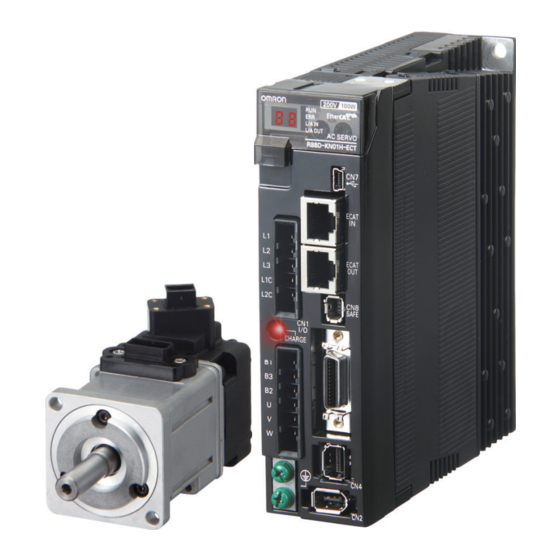
1-3 Names and Functions 1-3 Names and Functions This section describes the names and functions of Servo Drive parts. Servo Drive Part Names The Servo Drive part names are given below. EtherCAT status indicators Seven-segment display Analog monitor connector (CN5) Rotary switches for node address setting USB connector (CN7) -
Page 30: Servo Drive Functions
1-3 Names and Functions Servo Drive Functions The functions of each part are described below. Display A 2-digit 7-segment display shows the node address, error codes, and other Servo Drive status. Charge Lamp Lights when the main circuit power supply is turned ON. EtherCAT Status Indicators These indicators show the status of EtherCAT communications. -
Page 31: System Block Diagram
1-4 System Block Diagram 1-4 System Block Diagram This is the block diagram of the OMNUC G5-series AC Servo Drive with Built-in EtherCAT Communications. CN B CN A FUSE FUSE Internal Regeneration Resistor − Voltage detection FUSE − SW power 15 V Relay Overcurrent... -
Page 32: Applicable Standards
1-5 Applicable Standards 1-5 Applicable Standards This section describes applicable EMC Directives. EC Directives Product Applicable standards Directive AC Servo Drives EN 61800-5-1 Voltage AC Servomotors EN 60034-1/-5 Directive AC Servo Drives EN 55011 class A group 1 Directive AC Servomotors IEC 61800-3 EN 61000-6-2 Note: To conform to EMC Directives, the Servomotor and Servo Drive must be installed under the conditions described... - Page 33 Models and External Dimensions This chapter explains the models of Servo Drive, Servomotor, and peripheral devices, and provides the external dimensions and mounting dimensions. 2-1 Servo System Configuration ........2-1 2-2 How to Read Model Numbers ........2-3 2-3 Model Tables ..............2-5 2-4 External and Mounting Dimensions......2-19 2-5 EMC Filter Dimensions..........2-37 OMNUC G5-series AC Servomotors and Servo Drives User’s Manual (with Built-in EtherCAT Communications)
-
Page 34: Servo System Configuration
2-1 Servo System Configuration 2-1 Servo System Configuration Support Software Support Software Controller ● CX-One FA Integrated ● CX-One FA Integrated Tool Package Tool Package SYSMAC PLC Position Control Unit with EtherCAT Interface (Including CX-Drive) CX-Programmer, ● CX-Drive CX-Position, WS02-DRVC1 and CX-Motion Programmable Position Control Unit (NC) - Page 35 2-1 Servo System Configuration AC Servomotors AC Servo Drive Motor power signals Power Cables ● Flexible Cables communications • Without Brake R88A-CA@@@@@SR-E • With Brake R88A-CA@@@@@BR-E EtherCAT communications Brake Cables (50 to 750 W max.) ● Flexible Cable R88A-CAKA@@@BR-E Feedback Signals Encoder Cables ●...
-
Page 36: How To Read Model Numbers
2-2 How to Read Model Numbers 2-2 How to Read Model Numbers This section describes how to read and understand the model numbers of Servo Drives and Servomotors. Servo Drive The Servo Drive model number tells the Servo Drive type, applicable Servomotor capacity, power supply voltage, etc. -
Page 37: Servomotors
2-2 How to Read Model Numbers Servomotors The model number provides information such as the Servomotor type, motor capacity, rated rotation speed, and power supply voltage. R88M-KP10030H-BOS2 OMNUC G5-series Servomotor Motor Type Blank: Cylinder type Servomotor Capacity 050: 50 W 100: 100 W 200: 200 W 400: 400 W... -
Page 38: Model Tables
2-3 Model Tables 2-3 Model Tables This section lists the standard models of Servo Drives, Servomotors, Cables, Connectors, and peripheral equipment. Servo Drive Model Table The table below lists the Servo Drive models. Specifications Model Single-phase 100 VAC 50 W R88D-KNA5L-ECT-R 100 W R88D-KN01L-ECT-R... -
Page 39: Servomotor Model Tables
2-3 Model Tables Servomotor Model Tables The following tables list the Servomotor models by the rated motor speed. 3,000-r/min Servomotors Model With incremental encoder With absolute encoder Specifications Straight shaft Straight shaft Straight shaft Straight shaft without key with key and tap without key with key and tap 50 W R88M-K05030H... - Page 40 2-3 Model Tables 2,000-r/min Servomotors Model With incremental encoder With absolute encoder Specifications Straight shaft Straight shaft Straight shaft Straight shaft without key with key and tap without key with key and tap 1 kW R88M-K1K020H R88M-K1K020H-S2 R88M-K1K020T R88M-K1K020T-S2 200 V 1.5 kW R88M-K1K520H R88M-K1K520H-S2 R88M-K1K520T...
-
Page 41: Servo Drive And Servomotor Combination Tables
2-3 Model Tables Servo Drive and Servomotor Combination Tables The tables in this section show the possible combinations of OMNUC G5-series Servo Drives and Servomotors. The Servomotors and Servo Drives can only be used in the listed combinations. “-@” at the end of the motor model number is for options, such as the shaft type, brake, oil seal and key. - Page 42 2-3 Model Tables 1,000-r/min Servomotors and Servo Drives Servomotor Voltage Servo Drive Rated With incremental With absolute encoder output encoder Single- phase/3- 900 W R88M-K90010H-@ R88M-K90010T-@ R88D-KN15H-ECT-R phase 200 V Single- phase/3- 900 W R88M-K90010F-@ R88M-K90010C-@ R88D-KN15F-ECT-R phase 400 V OMNUC G5-series AC Servomotors and Servo Drives User’s Manual (with Built-in EtherCAT Communications)
-
Page 43: Cable And Peripheral Device Model Tables
2-3 Model Tables Cable and Peripheral Device Model Tables The following tables list the models of cables and peripheral devices. The cables include motor power cables, brake cables, encoder cables, EtherCAT communications cables, and absolute encoder battery cables. The peripheral devices include Connectors, External Regeneration Resistors, and Mounting Brackets. - Page 44 2-3 Model Tables Motor Power Cables (European Flexible Cables) Model Specifications For motor without brake For motor with brake [100 V and 200 V] 1.5 m R88A-CAKA001-5SR-E (See note.) For 3,000-r/min Servomotors of 50 to R88A-CAKA003SR-E 750 W R88A-CAKA005SR-E 10 m R88A-CAKA010SR-E 15 m R88A-CAKA015SR-E 20 m R88A-CAKA020SR-E [200 V]...
- Page 45 2-3 Model Tables Brake Cables (European Flexible Cables) Specifications Model [100 V and 200 V] 1.5 m R88A-CAKA001-5BR-E For 3,000-r/min Servomotors of 50 to 750 W R88A-CAKA003BR-E R88A-CAKA005BR-E 10 m R88A-CAKA010BR-E 15 m R88A-CAKA015BR-E 20 m R88A-CAKA020BR-E Encoder Cables (Global Non-flexible Cables) Specifications Model [100 V and 200 V]...
- Page 46 2-3 Model Tables Motor Power Cables (Global Non-flexible Cables) Model Specifications For motor without For motor with brake brake [100 V and 200 V] R88A-CAKA003S (See note.) For 3,000-r/min Servomotors of 50 to R88A-CAKA005S 750 W 10 m R88A-CAKA010S 15 m R88A-CAKA015S 20 m R88A-CAKA020S...
- Page 47 2-3 Model Tables Brake Cables (Global Non-flexible Cables) Specifications Model [100 V and 200 V] R88A-CAKA003B For 3,000-r/min Servomotors of 50 to 750 W R88A-CAKA005B 10 m R88A-CAKA010B 15 m R88A-CAKA015B 20 m R88A-CAKA020B 30 m R88A-CAKA030B 40 m R88A-CAKA040B 50 m R88A-CAKA050B Encoder Cables (Global Flexible Cables)
- Page 48 2-3 Model Tables Motor Power Cables (Global Flexible Cables) Model Specifications For motor without For motor with brake brake [100 V and 200 V] R88A-CAKA003SR (See note.) For 3,000-r/min Servomotors of 50 to R88A-CAKA005SR 750 W 10 m R88A-CAKA010SR 15 m R88A-CAKA015SR 20 m R88A-CAKA020SR...
- Page 49 2-3 Model Tables Brake Cables (Global Flexible Cables) Specifications Model [100 V and 200 V] R88A-CAKA003BR For 3,000-r/min Servomotors of 50 to 750 W R88A-CAKA005BR 10 m R88A-CAKA010BR 15 m R88A-CAKA015BR 20 m R88A-CAKA020BR 30 m R88A-CAKA030BR 40 m R88A-CAKA040BR 50 m R88A-CAKA050BR 2-16...
- Page 50 2-3 Model Tables EtherCAT Communications Cable (Recommended) Category 5 or higher (cable with double, aluminum tape and braided shielding) is recommended Absolute Encoder Battery Cables Name Model Absolute Encoder Battery Cable (battery not supplied) 0.3 m R88A-CRGD0R3C Absolute Encoder Battery Cable (R88A-BAT01G battery × 1 supplied) 0.3 m R88A-CRGD0R3C-BS Absolute Encoder Backup Battery...
- Page 51 2-3 Model Tables Control Cables Name Model Connector-terminal Block Cables XW2Z-100J-B34 XW2Z-200J-B34 Connector-terminal Block M3 screws XW2B-20G4 M3.5 screws XW2B-20G5 M3 screws XW2D-20G6 External Regeneration Resistors Specifications Model Regeneration process capacity: 20 W, 50 Ω (with 150°C thermal sensor) R88A-RR08050S Regeneration process capacity: 20 W, 100 Ω...
-
Page 52: External And Mounting Dimensions
2-4 External and Mounting Dimensions 2-4 External and Mounting Dimensions This section describes the external dimensions and the mounting dimensions of Servo Drives, Servomotors, and peripheral devices. Servo Drive Dimensions The dimensional description starts with a Servo Drive of the smallest motor capacity, which is followed by the next smallest, and so on. - Page 53 2-4 External and Mounting Dimensions Front Mounting (Using Front Mounting Brackets) External dimensions Mounting dimensions 19.5 φ5.2 φ5.2 Rectangular hole (42)* * Rectangular hole dimensions are reference values. 2-20 OMNUC G5-series AC Servomotors and Servo Drives User’s Manual (with Built-in EtherCAT Communications)
- Page 54 2-4 External and Mounting Dimensions Single-phase/3-phase 100 VAC: R88D-KN02L-ECT-R (200 W) Single-phase/3-phase 200 VAC: R88D-KN04H-ECT-R (400 W) Wall Mounting External dimensions Mounting dimensions φ5.2 Front Mounting (Using Front Mounting Brackets) External dimensions Mounting dimensions 19.5 φ5.2 φ5.2 Rectangular hole R2.6 (57)* * Rectangular hole dimensions are reference values.
- Page 55 2-4 External and Mounting Dimensions Single-phase/3-phase 100 VAC: R88D-KN04L-ECT-R (400 W) Single-phase/3-phase 200 VAC: R88D-KN08H-ECT-R (750 W) Wall Mounting External dimensions Mounting dimensions φ5.2 Front Mounting (Using Front Mounting Brackets) External dimensions Mounting dimensions 19.5 φ5.2 φ5.2 Rectangular hole R2.6 (67)* * Rectangular hole dimensions are reference values.
- Page 56 2-4 External and Mounting Dimensions Single-phase/3-phase 200 VAC: R88D-KN10H-ECT-R/-KN15H-ECT-R (900 W to 1.5 kW) Wall Mounting External dimensions Mounting dimensions φ5.2 Front Mounting (Using Front Mounting Brackets) External dimensions Mounting dimensions 19.5 φ5.2 φ5.2 φ5.2 Rectangular hole R2.6 R2.6 (88)* * Rectangular hole dimensions are reference values.
- Page 57 2-4 External and Mounting Dimensions 3-phase 400 VAC: R88D-KN06F-ECT-R/-KN10F-ECT-R (600 W to 1.0 kW) 3-phase 400 VAC: R88D-KN15F-ECT-R (1.5 kW) Wall Mounting External dimensions Mounting dimensions φ5.2 14.5 Front Mounting (Using Front Mounting Brackets) External dimensions Mounting dimensions 19.5 φ5.2 φ5.2 φ5.2 Rectangular...
-
Page 58: Servomotor Dimensions
2-4 External and Mounting Dimensions Servomotor Dimensions In this description, the Servomotors are grouped by rated rotation speed. The description starts with a Servomotor of the smallest capacity, which is followed by the next smallest, and so on. 3,000-r/min Servomotors (100 V and 200 V) 50 W/100 W (without Brake) R88M-K05030H (-S2)/-K10030@ (-S2) R88M-K05030T (-S2)/-K10030@ (-S2) - Page 59 2-4 External and Mounting Dimensions 50 W/100 W (with Brake) R88M-K05030H-B (S2)/-K10030@-B (S2) R88M-K05030T-B (S2)/-K10030@-B (S2) Encoder connector Brake connector Motor connector 40×40 (Shaft end specifications with key and tap) 12.5 R3.7 M3 (depth 6) 1.5 min. R4.2 2-φ4.3 Dimensions (mm) Model R88M-K05030@-B@ R88M-K10030@-B@...
- Page 60 2-4 External and Mounting Dimensions 200 W/400 W (without Brake) R88M-K20030@ (-S2)/-K40030@ (-S2) R88M-K20030@ (-S2)/-K40030@ (-S2) Encoder connector Motor connector 60×60 (Shaft end specifications with key and tap) 4-φ4.5 30 20 (200 W) 25 (400 W) 4h9 (200 W) 18 (200 W) 5h9 (400 W) 22.5 (400 W) M4, depth 8 (200 W)
- Page 61 2-4 External and Mounting Dimensions 750 W (without Brake) R88M-K75030H (-S2) R88M-K75030T (-S2) Encoder connector Motor connector 112.2 86.2 80×80 (Shaft end specifications with key and tap) 4-φ6 M5 (depth 10) Note: The standard models have a straight shaft. Models with a key and tap are indicated with S2 at the end of the model number.
- Page 62 2-4 External and Mounting Dimensions 1 kW/1.5 kW (without Brake) R88M-K1K030H (-S2)/-K1K530H (-S2) R88M-K1K030T (-S2)/-K1K530T (-S2) 1 kW/1.5 kW (with Brake) R88M-K1K030H-B (S2)/-K1K530H-B (S2) R88M-K1K030T-B (S2)/-K1K530T-B (S2) Motor and brake connector (Shaft end specifications with key and tap) Encoder connector 100×100 4-φ9 M3, through...
- Page 63 2-4 External and Mounting Dimensions 3,000-r/min Servomotors (400 V) 750 W/1 kW/1.5 kW (without Brake) R88M-K75030F (-S2)/-K1K030F (-S2)/-K1K530F (-S2) R88M-K75030C (-S2)/-K1K030C (-S2)/-K1K530C (-S2) 750 W/1 kW/1.5 kW (with Brake) R88M-K75030F-B (S2)/-K1K030F-B (S2)/-K1K530F-B (S2) R88M-K75030C-B (S2)/-K1K030C-B (S2)/-K1K530C-B (S2) Motor and brake connector Encoder connector (Shaft end specifications with key and tap)
- Page 64 2-4 External and Mounting Dimensions 2,000-r/min Servomotors (200 V) 1 kW/1.5 kW (without Brake) R88M-K1K020H (-S2)/-K1K520H (-S2) R88M-K1K020T (-S2)/-K1K520T (-S2) 1 kW/1.5 kW (with Brake) R88M-K1K020H-B (S2)/-K1K520H-B (S2) R88M-K1K020T-B (S2)-K1K520T-B (S2) Motor and brake connector (Shaft end specifications with key and tap) 130×130 Encoder connector 4-φ9...
- Page 65 2-4 External and Mounting Dimensions 2,000-r/min Servomotors (400 V) 400 W/600 W (without Brake) R88M-K40020F (-S2)/-K60020F (-S2) R88M-K40020C (-S2)/-K60020C (-S2) 400 W/600 W (with Brake) R88M-K40020F-B (S2)/-K60020F-B (S2) R88M-K40020C-B (S2)/-K60020C-B (S2) Motor and brake connector Encoder connector 100×100 (Shaft end specifications with key and tap) M3, through 4-φ9 M5 (depth 12)
- Page 66 2-4 External and Mounting Dimensions 1 kW/1.5 kW (without Brake) R88M-K1K020F (-S2)/-K1K520F (-S2) R88M-K1K020C (-S2)/-K1K520C (-S2) 1 kW/1.5 kW (with Brake) R88M-K1K020F-B (S2)/-K1K520F-B (S2) R88M-K1K020C-B (S2)/-K1K520C-B (S2) Motor and brake connector (Shaft end specifications with key and tap) Encoder 130×130 connector 4-φ9 M3, through...
- Page 67 2-4 External and Mounting Dimensions 1,000-r/min Servomotors (200 V) 900 W (without Brake) R88M-K90010H (-S2) R88M-K90010T (-S2) 900 W (with Brake) R88M-K90010H-B (S2) R88M-K90010T-B (S2) Motor and brake connector Encoder connector 130×130 (Shaft end specifications with key and tap) 77.5 4-φ9 M3, through M5 (depth 12)
- Page 68 2-4 External and Mounting Dimensions 1,000-r/min Servomotors (400 V) 900 W (without Brake) R88M-K90010F (-S2) R88M-K90010C (-S2) 900 W (with Brake) R88M-K90010F-B (S2) R88M-K90010C-B (S2) Motor and brake connector Encoder connector 130×130 (Shaft end specifications with key and tap) 4-φ9 M3, through M5 (depth 12) Dimensions (mm)
-
Page 69: External Regeneration Resistor Dimensions
2-4 External and Mounting Dimensions External Regeneration Resistor Dimensions External Regeneration Resistor R88A-RR08050S/-RR080100S Thermal switch output t1.2 R88A-RR22047S/-RR22047S1 Thermal switch output t1.2 R88A-RR50020S 2-36 OMNUC G5-series AC Servomotors and Servo Drives User’s Manual (with Built-in EtherCAT Communications) -
Page 70: Emc Filter Dimensions
2-5 EMC Filter Dimensions 2-5 EMC Filter Dimensions Drive mounts Output flexes External dimensions Mount dimensions Filter model R88A-FIK102-RE R88A-FIK104-RE R88A-FIK107-RE R88A-FIK114-RE R88A-FIK304-RE R88A-FIK306-RE R88A-FIK312-RE 2-37 OMNUC G5-series AC Servomotors and Servo Drives User’s Manual (with Built-in EtherCAT Communications) - Page 71 Specifications This chapter provides the general specifications, characteristics, connector specifications, and I/O circuits of the Servo Drives as well as the general specifications, characteristics, encoder specifications of the Servomotors and other peripheral devices. 3-1 Servo Drive Specifications ..........3-1 3-2 Overload Characteristics (Electronic Thermal Function)........3-27 3-3 Servomotor Specifications ........3-28 3-4 Cable and Connector Specifications ......3-42...
-
Page 72: Servo Drive Specifications
3-1 Servo Drive Specifications 3-1 Servo Drive Specifications Select a Servo Drive that matches the Servomotor to be used. Refer to Servo Drive and Servomotor Combination Tables on page 2-8. General Specifications Item Specifications Ambient operating 0 to 55°C, 90% max. (with no condensation) temperature and operating humidity Storage ambient temperature... -
Page 73: Characteristics
3-1 Servo Drive Specifications Characteristics 100-VAC Input Models R88D- R88D- R88D- R88D- Item KNA5L-ECT-R KN01L-ECT-R KN02L-ECT-R KN04L-ECT-R Continuous output current (rms) 1.2 A 1.7 A 2.5 A 4.6 A Input power Main Power supply circuit supply 0.4 KVA 0.4 KVA 0.5 KVA 0.9 KVA capacity... - Page 74 3-1 Servo Drive Specifications 200-VAC Input Models R88D- R88D- R88D- R88D- R88D- R88D- Item KN01H- KN02H- KN04H- KN08H- KN10H- KN15H- ECT-R ECT-R ECT-R ECT-R ECT-R ECT-R Continuous output current (rms) 1.2 A 1.6 A 2.6 A 4.1 A 5.9 A 9.4 A Input power Main...
- Page 75 3-1 Servo Drive Specifications 400-VAC Input Models Item R88D-KN06F-ECT-R R88D-KN10F-ECT-R R88D-KN15F-ECT-R Continuous output current (rms) 2.9 A 2.9 A 4.7 A Main Power circuit supply 3-phase 380 to 480 VAC (323 to 528 V) 50/60 Hz voltage Input power Rated 2.8 A 2.8 A 4.7 A...
-
Page 76: Ethercat Communications Specifications
3-1 Servo Drive Specifications EtherCAT Communications Specifications Item Specification Communications standard IEC 61158 Type 12, IEC 61800-7 CiA 402 Drive Profile Physical layer 100BASE-TX (IEEE802.3) RJ45 × 2 Connectors ECAT IN: EtherCAT input ECAT OUT: EtherCAT output Communications media Category 5 or higher (cable with double, aluminum tape and braided shielding) is recommended. -
Page 77: Main Circuit And Motor Connections
3-1 Servo Drive Specifications Main Circuit and Motor Connections When wiring the main circuit, use proper wire sizes, grounding systems, and noise resistance. R88D-KNA5L-ECT-R/-KN01L-ECT-R/-KN02L-ECT-R/-KN04L-ECT-R/-KN01H- ECT-R/-KN02H-ECT-R/-KN04H-ECT-R/-KN08H-ECT-R/-KN10H-ECT-R/- KN15H-ECT-R Main Circuit Connector Specifications (CNA) Symbol Name Function Main circuit power R88D-KN@L-ECT-R supply input 50 to 400 W: Single-phase 100 to 120 VAC (85 to 132 V) 50/60 Hz 200 to 400 W: 3-phase: 200 to 240 VAC (170 to 264 V) 50/60 Hz R88D-KN@H-ECT-R... - Page 78 3-1 Servo Drive Specifications R88D-KN06F-ECT-R/-KN10F-ECT-R/-KN15F-ECT-R Main Circuit Connector Specifications (CNA) Symbol Name Function Main circuit power supply R88D-KN@F-ECT-R input 600 W to 1.5 kW: 3-phase: 380 to 480 VAC (323 to 528 V) 50/60 Hz Motor Connector Specifications (CNB) Symbol Name Function Motor connection...
-
Page 79: Ethercat Communications Connector Specifications (Rj45)
3-1 Servo Drive Specifications EtherCAT Communications Connector Specifications (RJ45) The EtherCAT twisted-pair cable is connected to this connector. Electrical characteristics: Confirm to IEEE 802.3. Connector structure: RJ45 8-pin modular connector (conforms to ISO 8877) Pin No. Signal name Abbreviation Direction Send data + Output Send data −... -
Page 80: Control I/O Connector Specifications (Cn1)
3-1 Servo Drive Specifications Control I/O Connector Specifications (CN1) Control I/O Signal Connections and External Signal Processing 12 to 24 VDC +24 VIN 4.7 kΩ /ALM 10 Ω Error output Maximum ALMCOM General-purpose service 1 kΩ input 1 voltage: 10 Ω OUTM1 30 VDC 4.7 kΩ... - Page 81 3-1 Servo Drive Specifications Control I/O Signal Tables CN1 Control Inputs Signal Symbol Control mode number Name Default Power supply input 12 to 24 VDC. The positive input terminal of the external +24 VIN power supply (12 to 24 VDC) for sequence inputs General- Immediate...
- Page 82 3-1 Servo Drive Specifications CN1 Pin Arrangement Absolute General-purpose Encoder Backup OUTM1 Output 1 Absolute Battery Input General-purpose Encoder Backup OUTM1COM BATGND Output 1 Common Battery Input /ALM Error Output Signal Ground Error Output ALMCOM Common General-purpose Input 1 12 to 24-VDC +24 VIN Power Supply Input...
-
Page 83: Control Input Circuits
3-1 Servo Drive Specifications Control Input Circuits External power supply kΩ +24VIN 12 VDC ± 5% to 24 VDC ± 5% kΩ Photocoupler input Power supply capacity 50 mA or more (per unit) kΩ Signal level kΩ Photocoupler input ON level: 10 V or more OFF level: 3 V or less To another input circuit GND common To other input circuit... -
Page 84: Control Input Details
3-1 Servo Drive Specifications Control Input Details This is the detailed information about the CN1 connector input pins. General-purpose Inputs (IN1 to IN8) Pin 5: General-purpose Input 1 (IN1) Pin 7: General-purpose Input 2 (IN2) Pin 8: General-purpose Input 3 (IN3) Pin 9: General-purpose Input 4 (IN4) Pin 10: General-purpose Input 5 (IN5) - Page 85 3-1 Servo Drive Specifications Forward Drive Prohibition Input (POT) and Reverse Drive Prohibition Input (NOT) These two signals are the inputs to prohibit forward and reverse rotation (over-travel inputs). When these terminals are shorted (factory setting), the Servo Drive can rotate in the specified direction.
-
Page 86: Control Output Circuits
3-1 Servo Drive Specifications Monitor Inputs (MON0, MON1, and MON2) These are the general-purpose monitor inputs. The general-purpose monitor inputs do not affect operation and can be monitored from the host controller. With the default settings, MON0 is allocated to pin 13. Forward External Torque Limit Input (PCL) and Reverse External Torque Limit Input (NCL) Turn ON these inputs to limit the torque to the value set in the Forward External Torque Limit (3525... -
Page 87: Control Output Details
3-1 Servo Drive Specifications Control Output Details Control Output Sequence The chart below illustrates the timing of the command inputs after the control power supply is turned ON. Input the Servo ON/OFF operation, position, speed, and torque commands in the correct timing, as shown in the chart. - Page 88 3-1 Servo Drive Specifications Error Output (/ALM) Pin 3: Error Output (/ALM) Pin 4: Error Output Common (ALMCOM) Function This output is turned OFF when the drive detects an error. This output is OFF when the power supply is turned ON, but turns ON when the drive's initial processing has been completed.
- Page 89 3-1 Servo Drive Specifications Zero Speed Detection Output (ZSP) It turns ON when the motor rotation speed goes below the value set by the Zero Speed Detection (3434 hex). The output is effective both in forward and reverse directions regardless of the actual direction that the motor rotates.
-
Page 90: Encoder Connector Specifications (Cn2)
3-1 Servo Drive Specifications Encoder Connector Specifications (CN2) Pin No. Symbol Name Function and interface Encoder power supply +5 V Power supply output for the encoder Encoder power supply GND BAT+ Battery + Backup power supply output for the absolute encoder Battery −... - Page 91 3-1 Servo Drive Specifications Connection of External Encoder Input Signals and Processing of External Signals External encoder power supply output 5.2 V ± 5% 250 mA max +EXS -EXS Serial signal 4.7 k Ω +EXA Phase A 1.0 k Ω Photocoupler input -EXA 4.7 k Ω...
- Page 92 3-1 Servo Drive Specifications Example of Connection with External Encoder 90° Phase Difference Input (3323 Hex = 0) Servo Drive side (CN4) External encoder side 52 V ± 5% 250 mA max +5 V Power supply 4.7 k Ω +EXA Phase A 1.0 k Ω...
- Page 93 3-1 Servo Drive Specifications Serial Communications, Absolute Encoder Specifications (3323 Hex = 2) Absolute encoder by Mitutoyo Corporation Servo Drive side (CN4) ABS ST771A/ST773A 3 • 4 • 11 +5 V E0V 2 1 • 2 • 13 REQ/ +EXS -REQ/ Serial signal Shell...
-
Page 94: Monitor Connector Specifications (Cn5)
3-1 Servo Drive Specifications Monitor Connector Specifications (CN5) Monitor Output Signal Table Monitor Output (CN5) Pin No. Symbol Name Function and interface Analog monitor output 1 Outputs the analog signal for the monitor. Default setting: Motor rotation speed 1 V/(1,000 r/min) You can use objects 3416 hex and 3417 hex to change the item and unit. -
Page 95: Usb Connector Specifications (Cn7)
3-1 Servo Drive Specifications USB Connector Specifications (CN7) Through the USB connection with computer, operations such as parameter setting and changing, monitoring of control status, checking error status and error history, and parameter saving and loading can be performed. Pin No. Symbol Name Function and interface... -
Page 96: Safety Connector Specifications (Cn8)
3-1 Servo Drive Specifications Safety Connector Specifications (CN8) Connection of Safety I/O Signals and Processing of External Signals 4.7 kΩ SF1+ 12 to 24 VDC 1 kΩ 10 Ω SF1- EDM+ Maximum service voltage: 30 VDC or less Maximum output current: 50 mADC 4.7 kΩ... - Page 97 3-1 Servo Drive Specifications Safety Input Circuits Servo Drive SF1+ 4.7 kΩ External power supply Photocoupler 12 VDC ± 5% to 1.0 kΩ input 24 VDC ± 5% SF1- 4.7 kΩ SF2+ Photocoupler 1.0 kΩ input SF2- Signal level ON level: 10 V min. OFF level: 3 V max.
-
Page 98: Overload Characteristics (Electronic Thermal Function)
3-2 Overload Characteristics (Electronic Thermal Function) 3-2 Overload Characteristics (Electronic Thermal Function) An overload protection function (electronic thermal) is built into the Servo Drive to protect the drive and motor from overloading. If an overload does occur, first eliminate the cause of the error and then wait at least 1 minute for the motor temperature to drop before turning ON the power again. -
Page 99: Servomotor Specifications
3-3 Servomotor Specifications 3-3 Servomotor Specifications The following OMNUC G5-Series AC Servomotors are available. 3,000-r/min Servomotors 2,000-r/min Servomotors 1,000-r/min Servomotors There are various options available, such as models with brakes, or different shaft types. Select a Servomotor based on the mechanical system's load conditions and the installation environment. -
Page 100: Characteristics
3-3 Servomotor Specifications Characteristics 3,000-r/min Servomotors 100 VAC Model (R88M-) K05030H K10030L K20030L K40030L Item Unit K05030T K10030S K20030S K40030S Rated output * Rated torque * N • m 0.16 0.32 0.64 Rated rotation speed r/min 3,000 Maximum rotation speed r/min 6,000 Momentary maximum... - Page 101 3-3 Servomotor Specifications 200 VAC Model (R88M-) K05030H K10030H K20030H K40030H Item Unit K05030T K10030T K20030T K40030T Rated output * Rated torque * N • m 0.16 0.32 0.64 Rated rotation speed r/min 3,000 Momentary maximum r/min 6,000 rotation speed Momentary maximum N •...
- Page 102 3-3 Servomotor Specifications 200 VAC Model (R88M-) K75030H K1K030H K1K530H Item Unit K75030T K1K030T K1K530T Rated output * 1000 1500 Rated torque * N • m 3.18 4.77 Rated rotation speed r/min 3,000 Momentary maximum r/min 6,000 5,000 rotation speed Momentary maximum N •...
- Page 103 3-3 Servomotor Specifications 400 VAC Model (R88M-) K75030F K1K030F K1K530F Item Unit K75030C K1K030C K1K530C Rated output * 1000 1500 Rated torque * N • m 2.39 3.18 4.77 Rated rotation speed r/min 3,000 Momentary maximum r/min 5,000 rotation speed Momentary maximum N •...
- Page 104 3-3 Servomotor Specifications *1. These are the values when the motor is combined with a drive at normal temperature (20°C, 65%). The momentary maximum torque indicates the standard value. *2. Applicable load inertia. The operable load inertia ratio (load inertia/rotor inertia) depends on the mechanical configuration and its rigidity. For a machine with high rigidity, operation is possible even with high load inertia.
- Page 105 3-3 Servomotor Specifications 3,000-r/min Servomotors (200 VAC) The following graphs show the characteristics with a 3-m standard cable and a 200-VAC input. • R88M-K05030H/T (50 W) • R88M-K10030H/T (100 W) • R88M-K20030H/T (200 W) Power supply voltage Power supply voltage Power supply voltage (N •...
- Page 106 3-3 Servomotor Specifications Precautions for Correct Use Use the following Servomotors in the ranges shown in the graphs below. Usage outside of these ranges may cause the motor to generate heat, which could result in encoder malfunction. • R88M-K05030L/S/H/T • R88M-K10030L/S/H/T (50 W: With oil seal) (100 W: With oil seal) Without brake...
- Page 107 3-3 Servomotor Specifications 2,000-r/min Servomotors 200 VAC Model (R88M-) K1K020H K1K520H Item Unit K1K020T K1K520T Rated output * 1,000 1,500 Rated torque * N • m 4.77 7.16 Rated rotation speed r/min 2,000 Momentary maximum r/min 3,000 rotation speed Momentary maximum N •...
- Page 108 3-3 Servomotor Specifications 400 VAC Model (R88M-) K40020F K60020F K1K020F K1K520F Item Unit K40020C K60020C K1K020C K1K520C Rated output * 1,000 1,500 Rated torque * N • m 1.91 2.86 4.77 7.16 Rated rotation speed r/min 2,000 Momentary maximum r/min 3,000 rotation speed Momentary maximum...
- Page 109 3-3 Servomotor Specifications The operable load inertia ratio (load inertia/rotor inertia) depends on the mechanical configuration and its rigidity. For a machine with high rigidity, operation is possible even with high load inertia. Select an appropriate motor and confirm that operation is possible. If the dynamic brake is activated frequently with high load inertia, the Dynamic Brake Resistor may burn.
- Page 110 3-3 Servomotor Specifications 1,000-r/min Servomotors 200 VAC 400 VAC Model (R88M-) K90010H K90010F Item Unit K90010T K90010C Rated output * Rated torque * N • m 8.59 8.59 Rated rotation speed r/min 1,000 Momentary maximum rotation r/min 2,000 speed Momentary maximum torque * N •...
- Page 111 3-3 Servomotor Specifications *1. These are the values when the motor is combined with a drive at normal temperature (20°C, 65%). The momentary maximum torque indicates the standard value. *2. Applicable load inertia. The operable load inertia ratio (load inertia/rotor inertia) depends on the mechanical configuration and its rigidity. For a machine with high rigidity, operation is possible even with high load inertia.
-
Page 112: Encoder Specifications
3-3 Servomotor Specifications Encoder Specifications Incremental Encoder Specifications Item Specifications Encoder system Optical encoder 20 bits Number of output Phases A and B: 262,144 pulses/rotation pulses Phase Z: 1 pulse/rotation Power supply voltage 5 VDC ± 5% Power supply current 180 mA (max.) +S, −S Output signal... -
Page 113: Cable And Connector Specifications
3-4 Cable and Connector Specifications 3-4 Cable and Connector Specifications Encoder Cable Specifications These cables are used to connect the encoder between the Servo Drive and the Servomotor. Select the cable matching the Servomotor. The cables listed are flexible, shielded and have IP67 protection. - Page 114 3-4 Cable and Connector Specifications R88A-CRKC@NR Cable types (For both absolute encoders and incremental encoders: [100 V and 200 V] For 3,000-r/min Servomotors of 1 kW or more, [400 V] 3,000-r/min Servomotors, 2,000-r/min Servomotors and 1,000-r/min Servomotors) Outer diameter of Model Length (L) sheath...
-
Page 115: Motor Power Cable Specifications
3-4 Cable and Connector Specifications Motor Power Cable Specifications These cables connect the Servo Drive and the Servomotor. Select the cable matching the Servomotor. The cables listed are flexible, shielded and have IP67 protection. Power Cables without Brakes (European Flexible Cables) R88A-CAKA@SR-E Cable types [100 V and 200 V] (For 3,000-r/min Servomotors of 50 to 750 W) - Page 116 3-4 Cable and Connector Specifications R88A-CAGB@SR-E Cable types 200 V: (For 3,000-r/min Servomotors of 1 to 1.5 kW, 2,000-r/min Servomotors of 1 to 1.5 kW, 1,000-r/min Servomotors of 900 W) 400 V: (For 3,000-r/min Servomotors of 750W to 1.5 kW, 2,000-r/min Servomotors of 400 W to 1.5 kW, 1,000-r/min Servomotors of 900 W) Outer diameter of Model...
- Page 117 3-4 Cable and Connector Specifications Power Cables with Brakes (European Flexible Cables) R88A-CAGB@BR-E Cable types 200 V: (For 3,000-r/min Servomotors of 1 to 1.5 kW, 2,000-r/min Servomotors of 1 to 1.5 kW, 1,000-r/ min Servomotors of 900 W) Outer diameter of Model Length (L) sheath...
- Page 118 3-4 Cable and Connector Specifications R88A-CAKF@BR-E Cable types 400 V: (For 3,000-r/min Servomotors of 750W to 1.5 kW, 2,000-r/min Servomotors of 400 W to 1.5 kW, 1,000-r/min Servomotors of 900 W) Outer diameter of Model Length (L) sheath R88A-CAKF001-5BR-E 1.5 m R88A-CAKF003BR-E R88A-CAKF005BR-E 12.5 dia.
- Page 119 3-4 Cable and Connector Specifications Brake Cables (European Flexible Cables) R88A-CAKA@BR-E Cable types 100 and 200 V: (For 3,000-r/min Servomotors of 50 to 750 W) Outer diameter of Model Length (L) sheath R88A-CAKA001-5BR-E 1.5 m R88A-CAKA003BR-E R88A-CAKA005BR-E 6.0 dia. R88A-CAKA010BR-E 10 m R88A-CAKA015BR-E 15 m...
-
Page 120: Connector Specifications
3-4 Cable and Connector Specifications Connector Specifications Control I/O Connector (R88A-CNW01C) This is the connector to be connected to the drive's control I/O connector (CN1). Use this connector when preparing a control cable by yourself. Dimensions Connector plug model 10126-3000PE (Sumitomo 3M) Connector case model 10326-52A0-008 (Sumitomo 3M) t = 18... - Page 121 3-4 Cable and Connector Specifications R88A-CNK02R (Servomotor side) Applicable motors 100-V, 3,000-r/min Servomotors of 50 to 400 W Use the following cable. 200-V, 3,000-r/min Servomotors of 50 to 750 W Applicable wire: AWG22 max. Insulating cover outer diameter: 1.3 mm dia. max. Outer diameter of sheath: 5 ±...
- Page 122 3-4 Cable and Connector Specifications Power Cable Connector (R88A-CNK11A) This connector is used for power cables. Use it when preparing a power cable by yourself. 17.6 Angle plug direction can be reversed. R5.5 14.7 28.8 Angle plug model JN8FT04SJ1 (Japan Aviation Electronics) Socket contact model ST-TMH-S-C1B-3500-(A534G) (Japan Aviation Electronics) Brake Cable Connector (R88A-CNK11B)
-
Page 123: Ethercat Communications Cable Specifications
3-4 Cable and Connector Specifications EtherCAT Communications Cable Specifications For the EtherCAT communications cable, use a cable with double, aluminum tape and braided shielding of category 5 or higher. Precautions for Correct Use The maximum length between nodes is 100 m. However, some cables are specified for less than 100 m. - Page 124 3-4 Cable and Connector Specifications Attaching the Connectors to the Cable Use straight wiring for the communications cable, as shown below. Pin No. Wire color Wire color Pin No. White-Green White-Green Green Green White-Orange White-Orange Blue Blue White-Blue White-Blue Orange Orange White-Brown White-Brown...
- Page 125 3-4 Cable and Connector Specifications Wiring This example shows how to connect a CJ1W-NC281/NC481/NC881 Position Control Unit to Servo Drives using EtherCAT Communications Cables. Connect the EtherCAT master to the ECAT IN connector on the first Servo Drive. Connect the ECAT OUT connector on the first Servo Drive to the ECAT IN connector on the next Servo Drive.
-
Page 126: Analog Monitor Cable Specifications
3-4 Cable and Connector Specifications Analog Monitor Cable Specifications Analog Monitor Cable (R88A-CMK001S) Connection Configuration and External Dimensions Symbol Black White Cable: AWG24 × 3C UL1007 Connector housing: 51004-0600 (Molex Japan) Connector terminal: 50011-8100 (Molex Japan) 1,000 mm (1 m) 3-55 OMNUC G5-series AC Servomotors and Servo Drives User’s Manual (with Built-in EtherCAT Communications) - Page 127 3-4 Cable and Connector Specifications External Encoder Connector (R88A-CNK41L) Use this connector to connect to an external encoder in fully-closed control. (42.5) 13.6 (10.5) 10.4 Connector plug model MUF-PK10K-X (J.S.T. Mfg. Co., Ltd.) Pin Arrangement Safety I/O Signal Connector (R88A-CNK81S) Use this connector to connect to a safety device.
-
Page 128: Control Cable Specifications
Connector case: EXT1 EXT1 10326-52A0-008 (Sumitomo 3M) EXT2 EXT2 EXT3 EXT3 Terminal Block Connector BATGND BATGND Connector socket: XG4M-2030 (OMRON) BKIRCOM BKIRCOM Strain relief: BKIR BKIR XG4T-2004 (OMRON) ALMCOM ALMCOM Cable Shell AWG28 × 3P + AWG28 × 7C UL2464 * Before you use the Servo Drive, confirm that the signals of Servo Drive connector are set as shown above. - Page 129 3-4 Cable and Connector Specifications Connector-Terminal Block Conversion Unit (XW2B-20G@) The Unit is used with a Connector Terminal Block Cable (XW2Z-@J-B34). They convert the control input signal (CN1) of the G5-series Servo Drive into a terminal block. Terminal Block Models Model Description XW2B-20G4...
- Page 130 3-4 Cable and Connector Specifications XW2B-20G5 Dimensions Flat cable connector (MIL type plug) 112.5 φ Terminal block Note: The pitch of terminals is 8.5 mm. Precautions for Correct Use When using crimp terminals, use crimp terminals with the following dimensions. Fork terminal Round terminal φ3.7 mm...
- Page 131 3-4 Cable and Connector Specifications XW2D-20G6 Dimensions (39.1) 17.6 2- φ 4.5 Precautions for Correct Use When using crimp terminals, use crimp terminals with the following dimensions. Round terminal Fork terminal φ3.2mm mm max. mm max. 3.2 mm Applicable crimp terminals Applicable wires Round terminals 1.25 to 3...
- Page 132 3-4 Cable and Connector Specifications Terminal Block Wiring Example The example is for the XW2B-20G4, XW2B-20G5, and XW2D-20G6. +24 V +24 V +24 V STOP EXT1 EXT3 BKIR EXT2 BATGND BKIRCOM ALMCOM 24 VDC 24 VDC *1. Assign the brake interlock output (BKIR) to pin CN1-1. *2.
-
Page 133: External Regeneration Resistor Specifications
3-5 External Regeneration Resistor Specifications 3-5 External Regeneration Resistor Specifications External Regeneration Resistor Specifications R88A-RR08050S Regeneration Resis- Nominal absorption for Heat radiation Thermal switch Model tance val- capacity 120°C tempera- condition output specifications ture rise Operating temperature: 150°C ± 5% NC contact Aluminum R88A-... -
Page 134: External Regeneration Resistor Specifications
3-5 External Regeneration Resistor Specifications R88A-RR22047S1 Regeneration Resis- Nomi- absorption for Heat radiation Thermal switch Model tance val- nal ca- 120°C tempera- condition output specifications pacity ture rise Operating temperature: 150°C ± 5% NC contact Aluminum R88A- Rated output (resistive 47 Ω... -
Page 135: Emc Filter Specifications
3-6 EMC Filter Specifications 3-6 EMC Filter Specifications Specifications Applicable servo Leakage cur- Filter model Rated current Rated voltage drive rent R88D-KN01H-ECT-R R88A-FIK102-RE 2.4 A R88D-KN02H-ECT-R R88D-KN04H-ECT-R R88A-FIK104-RE 4.1 A 250 VAC single- phase R88D-KN08H-ECT-R R88A-FIK107-RE 6.6 A R88D-KN10H-ECT-R R88A-FIK114-RE 3.5 mA 14.2 A R88D-KN15H-ECT-R... - Page 137 System Design This chapter explains the installation conditions, wiring methods (including wiring conforming to EMC Directives), and regenerative energy calculation methods for the Servo Drive and Servomotor. It also explains the performance of External Regeneration Resistors. 4-1 Installation Conditions ..........4-1 4-2 Wiring................4-6 4-3 Wiring Conforming to EMC Directives......4-14 4-4 Regenerative Energy Absorption......4-32...
-
Page 138: Installation Conditions
4-1 Installation Conditions 4-1 Installation Conditions Servo Drive Installation Conditions Space Conditions around Servo Drives Install the Servo Drives according to the dimensions shown in the following illustration to ensure proper dispersion of heat from inside the drives and convection inside the panel. If the drives are installed side by side, install a fan for air circulation to prevent uneven temperatures inside the panel. -
Page 139: Servomotor Installation Conditions
4-1 Installation Conditions Ambient Temperature Control Operation in an environment in which there is minimal temperature rise is recommended to maintain a high level of reliability. When the drive is installed in a closed space, such as a box, the ambient temperature may rise due to temperature rise in each unit. - Page 140 4-1 Installation Conditions Connecting to Mechanical Systems For the allowable axial loads for motors, refer to Characteristics on page 3-2. If an axial load greater than that specified is Ball screw center line applied to a motor, it may reduce the limit of the motor bearings and may break the motor shaft.
- Page 141 4-1 Installation Conditions Oil-water Measures Use the Servomotor with an oil seal if you are using it in an environment where oil drops can adhere to the through-shaft part. The operating conditions of the Servomotor with an oil seal are as follows: Keep the oil level below the lip of the oil seal.
-
Page 142: Decelerator Installation Conditions
4-1 Installation Conditions Decelerator Installation Conditions Using Another Company's Decelerator (Reference) If the system configuration requires another company's decelerator to be used in combination with an OMNUC G5-series Servomotor, select the decelerator so that the loads on the motor shaft (i.e., both the radial and thrust loads) are within the allowable ranges. (Refer to Characteristics on page 3-2 for details on the allowable loads for the motors.) Also, select the decelerator so that the allowable input rotation speed and allowable input torque of the decelerator are not exceeded. -
Page 143: Wiring
24 VDC EMC Directives. *2. Recommended relay: MY relay by OMRON (24-V) For ALMCOM example, MY2 relay by OMRON can be used with all G5-series motors with brakes because its rated inductive 24 VDC load is 2 A (24 VDC). - Page 144 Wiring Confirming to EMC Directives. *2. Recommended relay: MY relay by /ALM OMRON (24-V) For example, MY2 relay 24 VDC by OMRON can be used with all ALMCOM G5-series motors with brakes because its rated inductive load is 2 A (24 VDC). 24 VDC BKIR *3.
- Page 145 Wiring Confirming to EMC Directives. *2. Recommended relay: MY relay by OMRON (24-V) For example, MY2 relay /ALM 24 VDC by OMRON can be used with all ALMCOM G5-series motors with brakes because its rated inductive load is 2 A (24 VDC). 24 VDC *3.
-
Page 146: Main Circuit And Motor Connections
4-2 Wiring Main Circuit and Motor Connections When wiring the main circuit, use proper wire sizes, grounding systems, and noise resistance. R88D-KNA5L-ECT-R/-KN01L-ECT-R/-KN02L-ECT-R/-KN04L-ECT-R/ R88D-KN01H-ECT-R/-KN02H-ECT-R/-KN04H-ECT-R/-KN08H-ECT-R/ R88-KN10H-ECT-R/-KN15H-ECT-R Main Circuit Connector Specifications (CNA) Sym- Name Function R88D-KN@L-ECT-R 50 to 400 W : Single-phase 100 to 120 VAC (85 to 132 V) 50/60 Hz 200 to 400 W: 3-phase 100 to 120 VAC (85 to 132 V) 50/60 Hz Main circuit power supply R88D-KN@H-ECT-R... - Page 147 4-2 Wiring R88D-KN06F-ECT-R/-KN10F-ECT-R/-KN15F-ECT-R Main Circuit Connector Specifications (CNA) Sym- Name Function Main circuit power supply R88D-KN@F-ECT-R input 600 W to 1.5 kW: 3-phase: 380 to 480 VAC (323 to 528 V) 50/60 Motor Connector Specifications (CNB) Sym- Name Function Motor connection These are the output terminals to the Servomotor.
- Page 148 N•m *1. The first value is for single-phase input power and the second value is for 3-phase input power. *2. Connect an OMRON power cable to the motor connection terminals. *3. Use the same wire size for B1 and B2.
- Page 149 Tightening N•m torque *1. Connect OMRON Power Cables to the motor connection terminals. *2. Use the same wire size for B1 and B2. Wire Sizes and Allowable Current (Reference) The following table shows the allowable current when there are 3 power supply wires. Use a current below these specified values.
- Page 150 4-2 Wiring Terminal Block Wiring Procedure On a Servo Drive with 2.0 kW or less, connector-type terminal blocks are used. The procedure for wiring these terminal blocks is explained below. Connector-type terminal blocks (Example of R88D-KN02H-ECT-R) 1. Remove the terminal block from the Servo Drive before wiring. The Servo Drive may be damaged if the wiring is done with the terminal block in place.
-
Page 151: Wiring Conforming To Emc Directives
4-3 Wiring Conforming to EMC Directives 4-3 Wiring Conforming to EMC Directives Conformance to the EMC Directives (EN 55011 Class A Group 1 (EMI) and EN 61000-6-2 (EMS)) can be ensured by wiring under the conditions described in this section. These conditions are for conformance of OMNUC G5-series products to the EMC directives. - Page 152 Okaya Electric 3SUP-HQ10-ER-6 3-phase 200 VAC (10 A) Noise filter Industries Co., Ltd. 3SUP-HU30-ER-6 3-phase 200 VAC (30 A) 3SUP-HL50-ER-6B 3-phase 200 VAC (50 A) − Servo Drive OMRON − Servomotor OMRON − Clamp core ZACT305-1330 − Clamp core Schaffner RJ8035...
- Page 153 4-3 Wiring Conforming to EMC Directives Noise Filter for Power Supply Input We recommend using a noise filter for the Servo Drive. Noise filter for power supply input Drive model Rated Leakage current Manufac- Model Phase current (60 Hz) max turer R88D-KNA5L-ECT-R Single-...
- Page 154 4-3 Wiring Conforming to EMC Directives Control Panel Structure Openings in the control panel, such as holes for cables, panel mounting holes, and gaps around the door, may allow electromagnetic waves into the panel. To prevent this, observe the recommendations described below when designing or selecting a control panel. Case Structure Use a metal control panel with welded joints at the top, bottom, and sides so that the surfaces are electrically conductive.
-
Page 155: Selecting Connection Component
4-3 Wiring Conforming to EMC Directives Selecting Connection Component This section explains the criteria for selecting the connection components required to improve noise resistance. Understand each component's characteristics, such as its capacity, performance, and applicable range when selecting the connection components. For more details, contact the manufacturers directly. - Page 156 4-3 Wiring Conforming to EMC Directives Leakage Breaker Select leakage breakers designed for protection against ground faults. Because switching takes place inside the Servo Drives, high-frequency current leaks from the SW elements of the Servo Drive, the armature of the motor, and the cables. High-frequency, surge-resistant leakage breakers, because they do not detect high-frequency current, can prevent operation with high-frequency leakage current.
- Page 157 4-3 Wiring Conforming to EMC Directives External Dimensions For single-phase (BWZ series) For 3-phase (BXZ series) φ 4.2 φ 4.2 1 2 3 Equalizing Circuits For single-phase (BWZ series) For 3-phase (BXZ series) (2) (3) 4-20 OMNUC G5-series AC Servomotors and Servo Drives User’s Manual (with Built-in EtherCAT Communications)
- Page 158 4-3 Wiring Conforming to EMC Directives Noise Filter for Power Supply Input We recommend using a noise filter for the Servo Drive. Noise filter for power supply input Leakage Drive model Rated Manufac- Model current current turer (60 Hz) max R88D-KNA5L-ECT-R 1.0 mA R88D-KN01L-ECT-R...
- Page 159 4-3 Wiring Conforming to EMC Directives External Dimensions SUP-EK5-ER-6/3SUP-HQ10-ER-6 100±2.0 53.1±2.0 88.0 75.0 Ground terminal 11.6 Attachment 13.0 screw for cover M3 Cover Noise filter unit 3SUP-HU30-ER-6 ±3.0 ±1.0 2- φ 5.5 2-φ5.5×7 Ground terminal Attachment screw for cover M3 Cover Noise filter unit...
- Page 160 Use one of the following filters to prevent switching noise of PWM of the Servo Drive and to prevent noise emitted from the internal clock circuit. Model Manufacturer Application 3G3AX-ZCL1 OMRON For Drive output and power cable 3G3AX-ZCL2 OMRON For Drive output and power cable ESD-R-47B...
- Page 161 4-3 Wiring Conforming to EMC Directives External Dimensions 3G3AX-ZCL1 3G3AX-ZCL2 3-M4 180±2 2-M5 160±2 ESD-R-47B ZCAT3035-1330 17.5 φ 5.1 4-24 OMNUC G5-series AC Servomotors and Servo Drives User’s Manual (with Built-in EtherCAT Communications)
- Page 162 4-3 Wiring Conforming to EMC Directives Impedance Characteristics 3G3AX-ZCL1 3G3AX-ZCL2 1000 1000 10000 Frequency (kHz) Frequency (kHz) ESD-R-47B ZCAT3035-1330 1000 10000 1000 1000 1000 Frequency (MHz) Frequency (MHz) 4-25 OMNUC G5-series AC Servomotors and Servo Drives User’s Manual (with Built-in EtherCAT Communications)
- Page 163 J7L-09-22200 11 A 200 VAC J7L-12-22200 13 A 200 VAC J7L-18-22200 18 A 200 VAC J7L-32-22200 26 A 200 VAC OMRON J7L-40-22200 35 A 200 VAC J7L-50-22200 50 A 200 VAC J7L-65-22200 65 A 200 VAC J7L-75-22200 75 A 200 VAC 4-26 OMNUC G5-series AC Servomotors and Servo Drives User’s Manual (with Built-in EtherCAT Communications)
- Page 164 4-3 Wiring Conforming to EMC Directives Improving Encoder Cable Noise Resistance Take the following steps during wiring and installation to improve the encoder's noise resistance. Always use the specified encoder cables. If cables are joined midway, be sure to use connectors. And do not remove more than 50 mm of the cable insulation.
- Page 165 4-3 Wiring Conforming to EMC Directives Improving Control I/O Signal Noise Resistance Positioning can be affected and I/O signal errors can occur if control I/O is influenced by noise. Use completely separate power supplies for the control power supply (especially 24 VDC) and the external operation power supply.
- Page 166 4-3 Wiring Conforming to EMC Directives Selecting Other Parts for Noise Resistance This section explains the criteria for selecting the connection components required to improve noise resistance. Understand each component's characteristics, such as its capacity, performance, and applicable range when selecting the connection components. For more details, contact the manufacturers directly.
- Page 167 Manufacturer Model Comment current 3G3AX-NF001 3G3AX-NF002 12 A 3G3AX-NF003 25 A OMRON For inverter output 3G3AX-NF004 50 A 3G3AX-NF005 75 A 3G3AX-NF006 100 A Note 1. Motor output lines cannot use the same noise filters for power supplies. Note 2. General noise filters are made for power supply frequencies of 50/60 Hz. If these noise filters are connected to output of the Servo Drive, a very large (about 100 times larger) leakage current may flow through the noise filter's capacitor.
- Page 168 4-3 Wiring Conforming to EMC Directives 3G3AX-NF003/-NF004/-NF005/-NF006 4- φ 6.5 Dimensions (mm) Model − − 3G3AX-NF003 3G3AX-NF004 3G3AX-NF005 3G3AX-NF006 4-31 OMNUC G5-series AC Servomotors and Servo Drives User’s Manual (with Built-in EtherCAT Communications)
-
Page 169: Regenerative Energy Absorption
4-4 Regenerative Energy Absorption 4-4 Regenerative Energy Absorption The Servo Drives have internal regeneration process circuitry, which absorbs the regenerative energy produced during motor deceleration and prevents the DC voltage from increasing. An overvoltage error occurs, however, if the amount of regenerative energy from the motor is too large. - Page 170 4-4 Regenerative Energy Absorption Vertical Axis Downward movement Motor operation Upward movement −N Motor output torque In the output torque graph, acceleration in the forward direction (rising) is shown as positive, and acceleration in the reverse direction (falling) is shown as negative. The regenerative energy values in each region can be derived from the following equations.
-
Page 171: Servo Drive Regeneration Absorption Capacity
4-4 Regenerative Energy Absorption Servo Drive Regeneration Absorption Capacity Amount of Internal Regeneration Absorption in Servo Drives This absorbs regenerative energy internally with built-in capacitors. Servo Drive If the regenerative energy is too large to be processed internally, an overvoltage error occurs and operation cannot continue. -
Page 172: Regenerative Energy Absorption With An External Regeneration Resistor
4-4 Regenerative Energy Absorption Regenerative Energy Absorption with an External Regeneration Resistor If the regenerative energy exceeds the regeneration absorption capacity of the Servo Drive, connect an External Regeneration Resistor. Connect the External Regeneration Resistor between B1 and B2 terminals on the Servo Drive. Double-check the terminal names when connecting the resistor because the drive may be damaged if connected to the wrong terminals. -
Page 173: Connecting An External Regeneration Resistor
4-4 Regenerative Energy Absorption Connecting an External Regeneration Resistor R88D-KNA5L-ECT-R/-KN01L-ECT-R/-KN02L-ECT-R/-KN01H-ECT-R/ R88D-KN02H-ECT-R/-KN04H-ECT-R Normally B2 and B3 are open. If an External Regeneration Resistor is necessary, connect the External Regeneration Resistor between B1 and B2 as shown in the diagram below. Servo Drive Thermal switch output θ... - Page 174 4-4 Regenerative Energy Absorption Combining External Regeneration Resistors Regeneration absorption 20 W 40 W 70 W 140 W capacity R88A-RR08050S R88A-RR08050S R88A-RR22047S R88A-RR22047S Model R88A-RR080100S R88A-RR080100S R88A-RR22047S1 R88A-RR22047S1 Resistance 50 Ω/100 Ω 25 Ω/50 Ω 47 Ω 94 Ω value Connection method Regeneration...
- Page 175 EtherCAT Communications This chapter describes EtherCAT communications under the assumption that the Servo Drive is connected to a CJ1W-NC281/NC481/NC881 Position Control Unit. 5-1 Display Area and Settings ...........5-1 5-2 Structure of the CAN Application Protocol over EtherCAT ......5-3 5-3 EtherCAT State Machine ..........5-4 5-4 Process Data Objects (PDOs)........5-5 5-5 Service Data Objects (SDOs)........5-7 5-6 Synchronization with Distributed Clocks....5-8...
-
Page 176: Display Area And Settings
5-1 Display Area and Settings 5-1 Display Area and Settings Status indicators @ RUN Rotary switches for @ ERR node address setting @ L/A IN @ L/A OUT Node Address Setting The rotary switches in the display area are used to set the EtherCAT node address. Description Rotary switch setting Connection to CJ1W-NC281/NC481/NC881... -
Page 177: Status Indicators
5-1 Display Area and Settings Status Indicators The following table shows the EtherCAT status indicators and their meaning. Name Color Status Description Init state Blinking Pre-Operational state Green Single flash Safe-Operational state Operational state No error Blinking Communications setting error Single flash Synchronization error or communications data error... -
Page 178: Structure Of The Can Application Protocol Over Ethercat
5-2 Structure of the CAN Application Protocol over EtherCAT 5-2 Structure of the CAN Application Protocol over EtherCAT The structure of the CAN application protocol over EtherCAT (CoE) for an OMNUC G5-series Servo Drive with built-in EtherCAT communications is described in this section. Servo Drive Application layer Servo drive application... -
Page 179: Ethercat State Machine
5-3 EtherCAT State Machine 5-3 EtherCAT State Machine The EtherCAT State Machine (ESM) of the EtherCAT slave is controlled by the EtherCAT Master. Init Pre-Operational Safe-Operational Operational SDO com- PDO re- State munica- transmis- Description ception tions sion Init Communications are being initialized. possible. -
Page 180: Process Data Objects (Pdos)
5-4 Process Data Objects (PDOs) 5-4 Process Data Objects (PDOs) The process data objects (PDOs) are used to transfer data during cyclic communications in realtime. PDOs can be reception PDOs (RxPDOs), which receive data from the controller, or transmission PDOs (TxPDOs), which send status from the Servo Drive to the host controller. RxPDO Operation command, target position, etc. -
Page 181: Sync Manager Pdo Assignment Settings
5-4 Process Data Objects (PDOs) Sync Manager PDO Assignment Settings A Sync manager channel consists of several PDOs. The Sync manager PDO assignment objects describe how these PDOs are related to the Sync Manager. The number of PDOs is given in sub-index 0 of the Sync manager PDO assignment table. In this table, index 1C12 hex is for RxPDOs and 1C13 hex is for TxPDOs. -
Page 182: Service Data Objects (Sdos)
5-5 Service Data Objects (SDOs) 5-5 Service Data Objects (SDOs) OMNUC G5-series Servo Drives support SDO communications. SDO communications are used for setting objects and monitoring the status of G5-series Servo Drives. Objects can be set and the status monitored by reading and writing data to the entries in the object dictionary of the host controller. -
Page 183: Synchronization With Distributed Clocks
5-6 Synchronization with Distributed Clocks 5-6 Synchronization with Distributed Clocks A mechanism called a distributed clock (DC) is used to synchronize EtherCAT communications. The DC mode is used for OMNUC G5-series Servo Drives to perform highly accurate control in a multi-axis system. In DC mode, the master and slaves are synchronized by sharing the same clock. -
Page 184: Emergency Messages
5-7 Emergency Messages 5-7 Emergency Messages When an error or warning occurs in a OMNUC G5-series Servo Drive, an emergency message is sent to the master using mailbox communications. An emergency message is not sent for a communications error. You can select whether to send emergency messages setting Diagnosis history (10F3 hex). The default setting is to not send emergency messages. - Page 185 6-3 Cyclic Synchronous Position Mode......6-5 6-4 Torque Limit ..............6-8 6-5 Touch Probe Function (Latch Function) ....6-9 6-6 Fully-closed Control ...........6-12 6-7 Object Dictionary ............6-19 6-8 Connecting with OMRON Controllers.......6-53 OMNUC G5-series AC Servomotors and Servo Drives User’s Manual (with Built-in EtherCAT Communications)
-
Page 186: Controlling The State Machine Of The Servo Drive
6-1 Controlling the State Machine of the Servo Drive 6-1 Controlling the State Machine of the Servo Drive The state of OMNUC G5-series Servo Drives with built-in EtherCAT communications is controlled by using the Controlword (6040 hex). Control state is given in the Statusword (6041 hex). - Page 187 6-1 Controlling the State Machine of the Servo Drive State Descriptions States Description Not ready to switch on The control circuit power supply is turned ON and initialization is being executed. Switch on disabled Initialization has been completed. Servo Drive parameters can be set. Ready to switch on The main circuit power supply can be turned ON.
- Page 188 6-1 Controlling the State Machine of the Servo Drive *3 Bit 7: Operation when Fault reset bit turns ON. Fault state: Errors are reset and the Servo Drive returns to its initialized state. If there are any warnings (Warning (6041 hex: Statusword bit 7), they are reset. State other than Fault state: If there are any warnings (Warning (6041 hex: Statusword bit 7), they are reset.
-
Page 189: Modes Of Operation
6-2 Modes of Operation 6-2 Modes of Operation OMNUC G5-series Servo Drives with built-in EtherCAT communications support the following Modes of operation. csp: Cyclic synchronous position mode The operation mode is set in Modes of operation (6060 hex). It is also given in Modes of operation display (6061 hex). -
Page 190: Cyclic Synchronous Position Mode
6-3 Cyclic Synchronous Position Mode 6-3 Cyclic Synchronous Position Mode In this mode of operation, the controller has a path generation function (an operation profile calculation function) and it gives the target position to the Servo Drive using cyclic synchronization. Position control, speed control, and torque control are performed by the Servo Drive. - Page 191 6-3 Cyclic Synchronous Position Mode Related Objects Sub- Default Index Name Access Size Unit Setting range index setting 6040 hex Controlword 0 to FFFF hex 0000h −2,147,483,648 to Target position Command 607A hex INT32 0000h units 2,147,483,647 Following error Command 0 to 134,217,728, or 6065 hex 100000...
-
Page 192: Block Diagram For Position Control Mode
6-3 Cyclic Synchronous Position Mode Block Diagram for Position Control Mode The following block diagram is for position control using an R88D-KN@@@-ECT-series Servo Drive. 6062 hex 4015 hex 4016 hex 607A hex 4017 hex Position demand Velocity Demand Motor Velocity Target position Motor Velocity value [command... -
Page 193: Torque Limit
6-4 Torque Limit 6-4 Torque Limit OMNUC G5-series Servo Drives can limit the torque using various methods. The following objects are used to limit the torque using EtherCAT communications. For details refer to Torque Limit Switching on page 7-21. Related Objects Index Name Description... -
Page 194: Touch Probe Function (Latch Function)
6-5 Touch Probe Function (Latch Function) 6-5 Touch Probe Function (Latch Function) The latch function latches the position actual value when an external latch input signal or the encoder's phase-Z signal turns ON. OMNUC G5-series Servo Drives can latch two positions. Related Objects Index Name... - Page 195 6-5 Touch Probe Function (Latch Function) General-purpose Input Assignment in (1) Signal Index Assignment 3404 hex Select either EXT1, EXT2, or EXT3. 3405 hex Select either EXT1, EXT2, or EXT3. 3406 hex Select either EXT1, EXT2, or EXT3. *1 The same function cannot be assigned more than once. Touch Probe Trigger Selection (3758 hex) in (2) Latch 1 Latch 2...
- Page 196 6-5 Touch Probe Function (Latch Function) Continuous (60B8 Hex Bit 1/9 = 1: Continuous) 60B8 hex Bit 0/8 Trigger input 60B9 hex Bit 0/8 60B9 hex Bit 1/9 60B9 hex Bit 6/14 60B9 hex Bit 7/15 60BA /60BC hex 6-11 OMNUC G5-series AC Servomotors and Servo Drives User’s Manual (with Built-in EtherCAT Communications)
-
Page 197: Fully-Closed Control
6-6 Fully-closed Control 6-6 Fully-closed Control An externally provided encoder is used to directly detect the position of the control target and feedback the detected machine position to perform position control. This way, controls can be performed without being affected by ball screw error, temperature changes, etc. You can achieve highly accurate positioning by configuring a fully-closed control system. -
Page 198: Objects Requiring Settings
6-6 Fully-closed Control Objects Requiring Settings Index Sub-index Name Description Reference Rotation Direction Set the relation between the command page 9-1 3000 hex Switching direction and the motor rotation direction. Control Mode Select the control mode. page 9-2 3001 hex Selection Motor revolutions Set the numerator of the electronic gear... - Page 199 6-6 Fully-closed Control Electronic Gear Function (6091-01 Hex, 6091-02 Hex) This function sets the position command for the position control part to the value that is calculated by multiplying the command from the Host Controller with the electronic gear ratio. Index Name Description...
- Page 200 6-6 Fully-closed Control *2 These are the directions in which the Servo Drive counts the pulses from an external encoder with a 90° phase difference outputs. Count-down direction Count-up direction EXB is 90° ahead of EXA. EXB is 90° behind EXA. t1 >...
- Page 201 6-6 Fully-closed Control External Feedback Pulse Dividing Ratio Setting (3324 Hex, 3325 Hex) Set the dividing ratio for the encoder resolution and external encoder resolution. Index Name Description Setting range Unit − External Set the numerator of the external feedback 0 to 1,048,576 Feedback Pulse pulse divider setting.
- Page 202 6-6 Fully-closed Control Hybrid Error Setting (3328 Hex, 3329 Hex) The difference between the encoder position and external encoder position is detected, and if the difference exceeds the value of Hybrid Following Error Counter Overflow Level (3328 hex), an error occurs. Index Name Description...
-
Page 203: Parameter Block Diagram For Fully-Closed Control Mode
6-6 Fully-closed Control Parameter Block Diagram for Fully-closed Control Mode The following is a block diagram for fully-closed control using an R88D-KN@@@-ECT-Series Servo Drive. 6062 hex 4015 hex 4016 hex 607A hex 4017 hex Position demand Velocity Demand Motor Velocity Target position Motor Velocity value [command... - Page 204 Definitions of variables that can be used by all 1000 to 1FFF hex servers for designated communications. Manufacturer Specific Area 1 Variables with common definitions for all OMRON 2000 to 2FFF hex products. Manufacturer Specific Area 2 Variables with common definitions for all OMNUC 3000 to 5FFF hex G5-series Servo Drives (servo parameters).
-
Page 205: Object Description Format
6-7 Object Dictionary Object Description Format In this manual, objects are described in the following format. Object Description Format The object format is shown below. <Object name> <Index> Modes of Operation Range <Range> Unit <Unit> Default <Default> Attribute <Attribute> Size <Size>... -
Page 206: Communication Objects
6-7 Object Dictionary Format When There Is Sub-indexing The object description format with subindices is shown below. <Object name> <Index> Modes of Operation Sub-index 0 Number of entries Range <Range> Unit <Unit> Default Attribute <Attribute> <Default > Size <Size> Access <Access>... - Page 207 6-7 Object Dictionary Error register 1001 hex Range − Unit Default Attribute − Size 1 byte (U8) Access PDO map Not possible Gives the error type that has occurred in the Servo Drive. Description of Set Values Description Description Generic error Communication error Current error Device profile specific error...
- Page 208 6-7 Object Dictionary This is not used by OMNUC G5-series Servo Drives. Manufacturer software version 100A hex − − Range Unit Default Attribute Size 20 bytes (VS) Access PDO map Not possible *1. The version number is saved in “V*.**”. Gives the version of the Servo Drive software.
- Page 209 6-7 Object Dictionary Index Sub-index Description 607C hex 00 hex Home offset 607D hex 01 hex Min position limit 607D hex 02 hex Max position limit 6091 hex 01 hex Motor revolutions 6091 hex 02 hex Shaft revolutions 60E0 hex 00 hex Positive torque limit value 60E1 hex...
- Page 210 6-7 Object Dictionary Identity object 1018 hex Sub-index 0 Number of entries − − − Range Unit Default 04 hex Attribute Size 1 byte (U8) Access PDO map Not possible Sub-index 1 Vender ID Range − Unit − Default 0000 0083 hex Attribute −...
- Page 211 6-7 Object Dictionary Backup parameter mode 10F0 hex Sub-index 0 Number of entries − − − Range Unit Default 02 hex Attribute Size 1 byte (U8) Access PDO map Not possible Sub-index 1 Backup parameter checksum Range − Unit − Default −...
-
Page 212: Pdo Mapping Objects
6-7 Object Dictionary PDO Mapping Objects Indexes 1600 to 17FF hex are used for Receive PDO mapping and indexes 1A00 to 1BFF hex are used for Transmit PDO mapping. Sub-indexes after sub-index 1 provide information about the application object being mapped. Index Sub-index Bit length... - Page 213 6-7 Object Dictionary 1B01 hex 258th TxPDO mapping parameter Sub-index 0 Number of objects − − − Range Unit Default 09 hex Attribute Size 1 byte (U8) Access PDO map Not possible Sub-index 1 1st object − − − Range Unit Default 603F 0010 hex...
-
Page 214: Sync Manager Communication Objects
6-7 Object Dictionary Sync Manager Communication Objects Objects 1C00 to 1C33 hex set how to use the EtherCAT communications memory. Sync manager communication type 1C00 hex Sub-index 0 Number of used sync manager channels − − − Range Unit Default 04 hex Attribute Size... - Page 215 6-7 Object Dictionary Sync manager 1 PDO assignment 1C11 hex Sub-index 0 Number of assigned PDOs Range − Unit − Default 00 hex Attribute − Size 1 byte (U8) Access PDO map Not possible The PDO mapping used by this sync manager is given. Mailbox reception sync manager does not have PDOs.
- Page 216 6-7 Object Dictionary SM2 synchronization 1C32 hex Sub-index 0 Number of synchronization parameters − − − Range Unit Default 20 hex Attribute Size 1 byte (U8) Access PDO map Not possible Sub-index 1 Synchronization type Range − Unit − Default 0002 hex Attribute −...
- Page 217 6-7 Object Dictionary SM3 synchronization 1C33 hex Sub-index 0 Number of synchronization parameters − − − Range Unit Default 20 hex Attribute Size 1 byte (U8) Access PDO map Not possible Sub-index 1 Synchronization type Range − Unit − Default 0002 hex Attribute −...
-
Page 218: Manufacturer Specific Objects
6-7 Object Dictionary Manufacturer Specific Objects This section describes objects specific to OMNUC G5-series Servo Drives with built-in EtherCAT communications. OMNUC G5-series Servo Drive parameters (Pn@@@) are allocated to objects 3000 to 3999 hex. Index 3@@@ hex corresponds to OMNUC G5-series Servo Drive parameter Pn@@@. - Page 219 6-7 Object Dictionary Statusword 1 4000 hex − − Range 0000 to FFFF hex Unit Default 0000 hex Attribute Size 2 bytes (U16) Access PDO map Possible This object gives the present state of the Servo Drive. Bit Descriptions Name Symbol Code Description...
- Page 220 6-7 Object Dictionary *2. When Servo Ready is 0, one of the following operations is being processed. It changes to 1 when all processing has been completed. : Writing to object using SDO mailbox communications. : Executing Config (4100 hex). : Resetting Warning/Error.
-
Page 221: Servo Drive Profile Object
6-7 Object Dictionary Servo Drive Profile Object This section describes the CiA402 drive profile supported by OMNUC G5-series Servo Drives. Error code 603F hex − − Range 0000 to FFFF hex Unit Default 0000 hex Attribute Size 2 bytes (U16) Access PDO map Possible... - Page 222 6-7 Object Dictionary Controlword 6040 hex − Range 0000 to FFFF hex Unit Default 0000 hex Attribute Size 2 bytes (U16) Access PDO map Possible This object controls the state machine of the Servo Drive. Description of Set Values Name Description Switch on The state is controlled by these bits.
- Page 223 6-7 Object Dictionary Bit Descriptions Name Description Ready to switch on These bits give the state. For details, refer to State Coding on page 6-3. Switched on Operation enabled Fault Voltage enabled Quick Stop Switch on disabled Warning This bit indicates that warning status exists. Operation continues without changing the status.
- Page 224 6-7 Object Dictionary Shutdown option code 605B hex −5 to 0 − −1 Range Unit Default Attribute Size 2 bytes (INT16) Access PDO map Not possible This object sets the (operation enable → ready to switch on) operation during shutdown. Description of Set Values Decelerating After stopping...
- Page 225 6-7 Object Dictionary Disable operation option code 605C hex −5 to 0 − −1 Range Unit Default Attribute Size 2 bytes (INT16) Access PDO map Not possible This object sets the operation during Disable operation (operation enable → switched on). Description of Set Values Decelerating After stopping...
- Page 226 6-7 Object Dictionary Fault reaction option code 605E hex −7 to 0 − −1 Range Unit Default Attribute Size 2 bytes (INT16) Access PDO map Not possible This object sets the behavior when an error occurs. Description of Set Values Decelerating After stopping value...
- Page 227 6-7 Object Dictionary Modes of operation 6060 hex − Range 0 to 10 Unit Default Attribute Size 1 byte (INT8) Access PDO map Possible This object sets the operation mode. The default value is 0 (Not specified). Set the operation mode from the master after the power supply is turned ON.
- Page 228 6-7 Object Dictionary This object gives the present position. Following error window 6065 hex 0 to 134217728, Command Range Unit Default 100000 Attribute 4294967295 units Size 4 bytes (U32) Access PDO map Not possible This object sets the threshold for following errors. If it is set to 4,294,967,295 (FFFF FFFF hex), detection of following errors is disabled.
- Page 229 6-7 Object Dictionary This object sets the target position in the Cyclic synchronous position mode. Home offset 607C hex −1073741823 to Command Range Unit Default Attribute 1073741823 units Size 4 bytes (INT32) Access PDO map Not possible This object sets the amount of offset from the origin of the absolute encoder or absolute external encoder to the zero position of the Position actual value (6064 hex).
- Page 230 6-7 Object Dictionary Gear ratio 6091 hex Sub-index 0 Number of entries − − − Range Unit Default 02 hex Attribute Size 1 byte (U8) Access PDO map Not possible Sub-index 1 Motor revolutions − Range 0 to 1073741824 Unit Default Attribute Size...
- Page 231 6-7 Object Dictionary Torque offset 60B2 hex Range −5000 to 5000 Unit 0.1% Default Attribute Size 2 bytes (INT16) Access PDO map Possible The value obtained by adding the value of this object (60B2 hex) and the torque feed-forward value calculated from the Control effort (60FA hex) and related objects (3112 hex and 3113 hex) is used as a torque feed-forward input value for the torque command which is calculated by comparing the Control effort (60FA hex) and the speed feedback.
- Page 232 6-7 Object Dictionary Touch probe status (Latch status) 60B9 hex − − − Range Unit Default Attribute Size 2 bytes (U16) Access PDO map Possible This object gives the status of the Touch probe function (Latch Function). Bit Descriptions Code Description Latch 1 is disabled.
- Page 233 6-7 Object Dictionary Positive torque limit value 60E0 hex Range 0 to 5000 Unit 0.1% Default 5000 Attribute Size 2 bytes (U16) Access PDO map Not possible This object sets the forward torque limit. It is limited by the maximum torque of the connected motor. For details refer to Torque Limit Switching on page 7-21.
- Page 234 6-7 Object Dictionary Signal name Symbol Code Description Encoder Phase Z Phase-Z signal not Detection detected during communication cycle Phase-Z signal detected during communication cycle External Latch Input 1 EXT1 External Latch Input 2 EXT2 External Latch Input 3 EXT3 Monitor Input 0 MON0 Monitor Input 1...
- Page 235 6-7 Object Dictionary Digital outputs 60FE hex Sub-index 0 Number of entries − − − Range Unit Default 02 hex Attribute Size 1 byte (U8) Access PDO map Not possible Sub-index 1 Physical outputs 0000 0000 to FFFF − Range Unit Default 0000 0000 hex...
- Page 236 6-7 Object Dictionary Bit Descriptions for Sub-index 2 Signal name Symbol Code Description Set brake Mask (Brake Interlock Set brake disable output BKIR Output Mask) Set brake enable output 1 to 15 Reserved − − − Remote Output 1 Mask R-OUT1 disable output R-OUT1 R-OUT1 enable output...
-
Page 237: Reserved Objects
6-7 Object Dictionary Supported drive modes 6502 hex 0000 0080 − − − Range Unit Default Attribute Size 4 bytes (U32) Access PDO map Not possible This object indicates the supported operation modes. Bit Descriptions Supported mode Definition pp (Profile position mode) 0: Not supported vl (Velocity mode) 0: Not supported... -
Page 238: Connecting With Omron Controllers
6-8 Connecting with OMRON Controllers 6-8 Connecting with OMRON Controllers This section describes the settings required to connect with an OMRON EtherCAT-compatible CJ1W-NC281/NC481/NC881 Position Control Unit Related Objects Objects listed in the following table must be used without changing them from their default values. - Page 239 Applied Functions This chapter outlines the applied functions such as the electronic gear, gain switching and soft start, and explains the settings. 7-1 Sequence I/O Signals ...........7-1 7-2 Forward and Reverse Drive Prohibition Functions ...7-6 7-3 Overrun Protection ............7-9 7-4 Backlash Compensation ..........7-11 7-5 Brake Interlock............7-13 7-6 Electronic Gear Function ...........7-18 7-7 Torque Limit Switching ..........7-21...
-
Page 240: Sequence I/O Signals
7-1 Sequence I/O Signals 7-1 Sequence I/O Signals You can set sequences in various operating conditions. For the connection of I/O signals and processing of external signals, refer to Control I/O Connector Specifications (CN1) on page 3-9. Input Signals You can allocate input signal functions to the input pins of the control I/O connector (CN1). In addition, you can change logic. - Page 241 7-1 Sequence I/O Signals Objects That Can Be Assigned Use the following objects when changing the input signal allocations. For the setting method, refer to Input Signal Allocation Method on page 7-2. Index Name Explanation Reference Set the IN1 input function allocation. This 3400 hex Input Signal Selection 1 object is based on hexadecimal.(The display...
- Page 242 7-1 Sequence I/O Signals Function Number Table The set values to be used for allocations are as follows: Set value Signal name Symbol Disabled − 00 hex Setting not available Forward Drive Prohibition Input 01 hex 81 hex Reverse Drive Prohibition Input 02 hex 82 hex Immediate Stop Input...
-
Page 243: Output Signals
7-1 Sequence I/O Signals Output Signals You can allocate output signal functions to the output pins for the control I/O connector (CN1). If a G-series Servo Drive is being replaced with a G5-series Servo Drive, use the G5-series Servo Drive to with the default settings. Output Signal Default Setting The allocations of the default output signals are as follows. - Page 244 7-1 Sequence I/O Signals Example: Position control or fully-closed control: Position command output (0B hex) 0007 050B hex Position control/fully-closed control Function Number Table The set values to be used for allocations are as follows: Set value Signal name Symbol NO (or normally open) NC (or normally close) contact...
-
Page 245: Forward And Reverse Drive Prohibition Functions
7-2 Forward and Reverse Drive Prohibition Functions 7-2 Forward and Reverse Drive Prohibition Functions If the Forward Drive Prohibition Input (POT) or the Reverse Drive Prohibition Input (NOT) is turned OFF, the motor will stop rotating. You can thus prevent the motor from rotation outside of the movement range of the device by using limit inputs from the device connected to the Servo Drive. - Page 246 7-2 Forward and Reverse Drive Prohibition Functions Drive Prohibition Input Selection (3504 Hex) Set the operation of the Forward Drive Prohibition Input (POT) and the Reverse Drive Prohibition Input (NOT). Install limit switches at both ends of the axis to prohibit the Servomotor from driving in the direction specified by the switch.
- Page 247 7-2 Forward and Reverse Drive Prohibition Functions Deceleration method Stop status Stop Selection for Drive Prohibition Input (3505 hex) Decelerate with dynamic brake Servo free POT or NOT opens. Decelerate in the free-run status Stop with Immediate Stop Servo locked Torque (3511 hex) Precautions for Correct Use At an immediate stop, an Error Counter Overflow (Error No.
-
Page 248: Overrun Protection
7-3 Overrun Protection 7-3 Overrun Protection This function detects an Overrun Limit Error (Error No. 34.0) and stops the Servomotor if the motor exceeds the allowable operating range set for the Overrun Limit Setting (3514 hex) with respect to the position command input. The function can also prevent the Servomotor from clash into the machine edge due to vibration. -
Page 249: Operation Example
7-3 Overrun Protection Operation Example No Position Command Input (Servo ON) No position command is entered. The Servomotor's allowable operating range is the range set in object 3514 hex on both the right and left. An overrun limit error will occur (Error No. 34.0) if the load enters the error range, or the shaded area in the drawing below, due to vibration. -
Page 250: Backlash Compensation
7-4 Backlash Compensation 7-4 Backlash Compensation The function compensates for backlash for position control and fully-closed control. Objects Requiring Settings Index Name Description Reference page Backlash Select whether to enable or disable backlash 3704 hex Compensation compensation during position control. page 9-46 Selection Set the compensation direction. - Page 251 7-4 Backlash Compensation Precautions for Correct Use To determine the actual position of the Servomotor, offset the Servomotor position data acquired via EtherCAT communications by the backlash compensation amount. Backlash compensation is performed on the first position command in the set direction after the servo is turned ON.
-
Page 252: Brake Interlock
7-5 Brake Interlock 7-5 Brake Interlock This function lets you set the output timing for the brake interlock output (BKIR) that activates the holding brake when the servo is turned ON, an error occurs, or the servo is turned OFF. The brake can also be controlled via EtherCAT communications. -
Page 253: Operation Timing
7-5 Brake Interlock Operation Timing This section shows the timing of the Brake Interlock Output (BKIR). Basic Timing Control power supply (L1C and L2C) Servo ON/OFF Servo OFF Servo ON Servo OFF Brake Interlock Request to release brake Output (BKIR) Forced-braking is possible. - Page 254 7-5 Brake Interlock Servo ON/OFF Operation Timing When Motor Is Operating Based on these operation timings, regenerative energy is produced if the motor rotation stops abnormally. Accordingly, repeated operation cannot be performed. Provide a wait time of at least 10 minutes for the motor to cool down. Servo ON/OFF Servo OFF Servo ON...
- Page 255 7-5 Brake Interlock Operation Timing When an Error Occurs (Servo ON) Error status Normal Error 0.5 to 5 ms Motor power supply Power supply No power supply Dynamic brake relay DB Released DB engaged Servo ready READY output (READY) Error Output (/ALM) Normal Error When object 3438 hex...
- Page 256 7-5 Brake Interlock Operation Timing When Resetting Errors Reset Error reset command 16 ms or more Servo ready READY output (READY) Error Output (/ALM) Error Normal 0 ms or more Servo ON/OFF Servo ON Servo OFF 2 ms or more Dynamic brake relay Brake Engaged Brake Released...
-
Page 257: Electronic Gear Function
7-6 Electronic Gear Function 7-6 Electronic Gear Function This function controls the position by using the value multiplied the position command entered on the Host Controller by the preset electronic gear ratio. The functions is used in the Position Control and Fully-closed Control modes. (This applies only when the communications cycle is 1, 2, or 4 ms.) For communications cycles for which the electronic gear is not supported (250 or 500 µs), a Function Setting Error (Error No. - Page 258 7-6 Electronic Gear Function Gear ratio Setting (6091-01 and 6091-02 Hex) Motor Shaft revolutions revolutions Description (6091-01 (6091-02 hex) hex) When the Motor revolutions (6091-01 hex) is 0, the processing changes with the set value of Shaft revolutions (6091-02 hex). Position command Encoder resolution*1 Position command Shaft revolutions (6091-02 hex)
-
Page 259: Operation Example
7-6 Electronic Gear Function Operation Example The example uses a motor with a 20- bit encoder (1,048,576 pulses per rotation) When the Motor Revolutions (6091-01 Hex) Is Set to 0 If you set 6091-02 hex to 2,000, the operation is the same as the 2,000 (pulses/rotation) Servomotor. -
Page 260: Torque Limit Switching
7-7 Torque Limit Switching 7-7 Torque Limit Switching This function switches the torque limit according to the operation direction, and depending on the Forward External Torque Limit (PCL), the Reverse External Torque Limit (NCL), and the Forward/Reverse Torque Limit Input Commands from EtherCAT communications. This function is used in the following conditions. - Page 261 7-7 Torque Limit Switching Torque Limits in Position Control Mode or Fully-closed Control Mode The term Torque FF refers to the torque feed-forward function. Position Control/Fully-closed Control Forward torque limit value Reverse torque limit value value Torque FF PCL ON PCL OFF NCL ON NCL OFF...
-
Page 262: Gain Switching Function
7-8 Gain Switching Function 7-8 Gain Switching Function This function switches the position loop and speed loop gain. Select enable or disable using Gain Switching Input Operating Mode Selection (3114 hex). Set the switching condition using the gain switching setting. If the load inertia changes or you want to change the responsiveness depending on whether the motor is stopping or operating, you can perform optimal control by using gain switching. -
Page 263: Objects Requiring Settings
7-8 Gain Switching Function Objects Requiring Settings Index Name Description Reference Realtime Autotuning Mode Set the operation mode for realtime autotuning. 3002 hex Selection Realtime autotuning cannot be used if the gain switching page 9-2 function is being used. Gain Switching Input Set whether to enable or disable the gain switching function. -
Page 264: Gain Switching
7-8 Gain Switching Function Gain Switching Refer to Chapter 9 Details on Servo Parameter Objects for details on gain-related objects. Position Control Mode and Fully-closed Control Mode In the Position Control mode and Fully-closed Control Mode, operation varies as follows according to switching mode in Position Control (3115 hex). - Page 265 7-8 Gain Switching Function *6. When the set value is 10, the meanings of the Gain Switching Delay Time in Position Control, the Gain Switching Level in Position Control, and the Gain Switching Hysteresis in Position Control differ from the normal case. (Refer to Figure E). Figure A Figure C Rotation...
-
Page 266: Diagrams Of Gain Switching Setting
7-8 Gain Switching Function Diagrams of Gain Switching Setting Switching between Gain 1 (3100 to 3104 hex) and Gain 2 (3105 to 3109 hex) occurs at the following timing. For the position loop gain, switching occurs based on the setting of 3119 hex. The details of the gain switching settings vary depending on the control mode used. - Page 267 7-8 Gain Switching Function Gain Switching Mode = 5 or 9: Switching by Speed Command or Actual Motor Speed Speed command or actual motor speed 3118 hex 3118 hex 3117 hex 3116 hex Gain 1 Gain 1 Gain 2 Note: The “speed command” is the Motor Control Effort (401A hex) [r/min]. Gain Switching Mode = 6: Switching by Pulse Position Error The gain is switched according to the pulse position error [encoder pulses/external encoder pulses].
- Page 268 7-8 Gain Switching Function Gain Switching Mode = 10: Switching by Combination of Whether There Is a Position Command and Actual Motor Speed Switching to the gain 2 occurs when a position command is received. If there is no position command but the absolute value of the actual motor speed remains less than the difference of the Gain Switching Level in Position Control (3117 hex) minus the Gain Switching Hysteresis in Position Control (3118 hex) [r/min] for the time specified in the Gain Switching Delay Time in Position Control (3116 hex), the gain switches to gain 1.
-
Page 269: Gain Switching 3 Function
7-9 Gain Switching 3 Function 7-9 Gain Switching 3 Function This function adds a new setting (gain 3) to the gain switching function of the Gain Switching Input Operating Mode Selection (3114 hex). It switches the gain right before a stop. The positioning time can be reduced by keeping the gain immediately before the stop at a higher level for a certain period of time. -
Page 270: Operation Example
7-9 Gain Switching 3 Function Operation Example When the conventional gain switching function works correctly, set the time to use Gain 3 in Gain 3 Effective Time (3605 hex), and the magnification of Gain 3 against Gain 1 in the Gain 3 Ratio Setting (3606 hex). -
Page 271: Chapter 8 Safety Function (Application Pending)
Safety Function (Application Pending) This function stops the Servomotor based on a signal from a safety controller or safety sensor. An outline of the function is given together with operation and connection examples. 8-1 Safe Torque OFF Function...........8-1 8-2 Operation Example ............8-4 8-3 Connection Examples ..........8-6 OMNUC G5-series AC Servomotors and Servo Drives User’s Manual (with Built-in EtherCAT Communications) -
Page 272: Safe Torque Off Function
8-1 Safe Torque OFF Function 8-1 Safe Torque OFF Function The safe torque OFF function (hereinafter referred to as STO according to IEC 61800-5-2) (application pending) is used to cut off the motor current and stop the motor through the input signals from a safety device, such as a safety controller or safety sensor, that is connected to the safety connector (CN8). -
Page 273: I/O Signal Specifications
8-1 Safe Torque OFF Function I/O Signal Specifications Safety Input Signals There are 2 safety input circuits to operate the STO function. Control mode Signal Symbol Description name number Posi- Fully- Speed Torque tion closed Safety √ √ √ √ CN8-4 •... - Page 274 8-1 Safe Torque OFF Function External Device Monitor (EDM) Output Signal This is a monitor output signal that is used to monitor the status of safety input signals using an external device. Connect a safety device, such as a safety controller or a safety sensor. Connect the EDM output signal to the monitoring terminal on a safety device.
-
Page 275: Operation Example
8-2 Operation Example 8-2 Operation Example Operation Timings to a Safety Status Servo ON/OFF Servo ON Servo OFF STO status Safety input 1 Normal status Safety input 2 max 5 ms Motor power is Power supply No power supply supplied. max 6 ms EDM output 0.5 to 5 ms... - Page 276 8-2 Operation Example Timing of Return from Safety Status Servo ON /OFF Servo OFF command Servo ON After the servo Safety input 1 Normal status STO status turns ON, operation Safety input 2 will follow the normal servo Motor power No power supply ON/OFF operation is supplied.
-
Page 277: Connection Examples
8-3 Connection Examples 8-3 Connection Examples Connection Example: Connection with a Safety Controller EDM input Safety Servo Drive controller SF1+ Safety input SF1- G9SX-AD SF2+ SF2- EDM+ EDM- EDM output Safety output (source) OMNUC G5-series AC Servomotors and Servo Drives User’s Manual (with Built-in EtherCAT Communications) - Page 279 Details on Servo Parameter Objects This chapter explains the settings of each object. 9-1 Basic Settings ...............9-1 9-2 Gain Settings..............9-6 9-3 Vibration Suppression Settings ........9-15 9-4 Analog Control Objects..........9-21 9-5 Interface Monitor Settings .........9-24 9-6 Extended Objects ............9-32 9-7 Special Objects ............9-38 9-8 Reserved Objects ............9-50 OMNUC G5-series AC Servomotors and Servo Drives User’s Manual (with Built-in EtherCAT Communications)
-
Page 280: Basic Settings
9-1 Basic Settings 9-1 Basic Settings Some objects are enabled by turning the power supply OFF and then ON again. After changing these objects, turn OFF the power supply, confirm that the power supply indicator has gone OFF, and then turn ON the power supply again. Do not change the objects marked "reserved."... - Page 281 9-1 Basic Settings Control Mode Selection 3001 hex Setting Default Data − 0 to 6 Unit range setting attribute Size 2 bytes (INT16) Access PDO map Not possible. Set the control mode to be used. Explanation of Set Values Set value Description 0 to 5 Semi-closed control (position control)*1...
- Page 282 9-1 Basic Settings ←Machine rigidity→ High ←Servo gain→ High 3003h 0.1 - - - - - - - - - - - - - - - 31 ←Responsiveness→ High Refer to 11-3 Realtime Autotuning on page 11-6. Precautions for Correct Use If the set value is changed suddenly by a large amount, the gain may change rapidly, subjecting the machine to shock.
- Page 283 9-1 Basic Settings Regeneration Resistor Selection 3016 hex Setting Default Data 0 to 3 Unit − range setting attribute Size 2 bytes (INT16) Access PDO map Not possible. *1. The default setting is 0 for a Drive with 100 V and 400 W, with 200 V and 750 W or greater, or with 400 V. The setting is different whether the Regeneration Resistor built in the Drive is directly used, or it is removed and replaced by an external regeneration resistor.
- Page 284 9-1 Basic Settings Explanation of Set Values Set value Description Regeneration load ratio is 100% when operating rate of the External Regeneration Resistor is 10%. Reserved Reserved Reserved Reserved OMNUC G5-series AC Servomotors and Servo Drives User’s Manual (with Built-in EtherCAT Communications)
-
Page 285: Gain Settings
9-2 Gain Settings 9-2 Gain Settings Refer to 11-2 Gain Adjustment on page 11-4 for the settings for gain adjustment. Position Loop Gain 1 3100 hex Setting Default Data 0 to 30000 Unit 0.1/s range setting attribute Size 2 bytes (INT16) Access PDO map Not possible. - Page 286 9-2 Gain Settings If the speed loop gain and position loop gain are optimally set, the motor operation for the command delays 2/Kp at acceleration and delays 3/Kp at deceleration. Motor speed Position command Motor operation Time Speed Loop Gain 1 3101 hex Setting Default...
- Page 287 9-2 Gain Settings Speed Loop Integral Time Constant 1 3102 hex Setting Default Data 1 to 10000 Unit 0.1 ms range setting attribute Size 2 bytes (INT16) Access PDO map Not possible. *1. The default setting is 310 for a Drive with 200 V and 1 kW or greater, or with 400 V. Set the speed loop integral time constant.
- Page 288 9-2 Gain Settings Speed Loop Gain 2 3106 hex Setting Default Data 1 to 32767 Unit 0.1 Hz range setting attribute Size 2 bytes (INT16) Access PDO map Not possible. *1. The default setting is 180 for a Drive with 200 V and 1 kW or greater, or with 400 V. Set the responsiveness of the second speed loop.
- Page 289 9-2 Gain Settings 3111 hex Speed Feed-forward Command Filter Setting Default Data 0 to 6400 Unit 0.01 ms range setting attribute Size 2 bytes (INT16) Access PDO map Not possible. Set the time constant for the first-order lag filter inserted into the feed-forward. Setting the filter may improve operation if speed overshooting occurs or the noise during operation is large when the feed-forward is set high.
- Page 290 9-2 Gain Settings Switching Mode in Position Control 3115 hex Setting Default Data − 0 to 10 Unit range setting attribute Size 2 bytes (INT16) Access Not possible. Select the conditions for switching between gain 1 and gain 2 when the Gain Switching Input Operating Mode Selection (3114 hex) is set to 1.
- Page 291 9-2 Gain Settings *6. When the set value is 10, meanings of the Gain Switching Delay Time in Position Control, the Gain Switching Level in Position Control, and the Gain Switching Hysteresis in Position Control differ from the normal case. (Refer to Figure E). Figure A Figure C Speed V...
- Page 292 9-2 Gain Settings Gain Switching Level in Position Control 3117 hex Setting Default Data − 0 to 20000 Unit range setting attribute Size 2 bytes (INT16) Access PDO map Not possible. This object is enabled when the Switching Mode in Position Control (3115 hex) is 3, 5, 6, 9 or 10. It sets the judgment level for switching between gain 1 and gain 2.
- Page 293 9-2 Gain Settings Position Loop Gain 1 < Position Loop Gain 2 Position Loop Gain 2 Position Loop Gain 1 Position Gain Switching Time (3119 hex) Position Position Position Loop Gain 1 Loop Gain 2 Loop Gain 1 Precautions for Correct Use When the position loop gain is switched to a smaller value (e.g., when switching from gain 2 to gain 1 in the above figure), Position Gain Switching Time (3119 hex) is ignored and the gain is switched immediately.
-
Page 294: Vibration Suppression Settings
9-3 Vibration Suppression Settings 9-3 Vibration Suppression Settings Adaptive Filter Selection 3200 hex Setting Default Data 0 to 4 Unit − range setting attribute Size 2 bytes (INT16) Access PDO map Not possible. Set the operation of the adaptive filter. Refer to 11-6 Adaptive Filter on page 11-18. - Page 295 9-3 Vibration Suppression Settings Notch 2 Frequency Setting 3204 hex Setting Default Data 50 to 5000 Unit 5000 range setting attribute Size 2 bytes (INT16) Access PDO map Not possible. Set the notch frequency of resonance suppression notch filter 2. The notch filter function is disabled if this object is set to 5000.
- Page 296 9-3 Vibration Suppression Settings Set the notch depth of resonance suppression notch filter 3. Increasing the setting value shortens the notch depth and the phase lag. While the adaptive filter is enabled, this object is set automatically. Refer to 11-6 Adaptive Filter on page 11-18 and 11-7 Notch Filters on page 11-21. Notch 4 Frequency Setting 3210 hex Setting...
- Page 297 9-3 Vibration Suppression Settings Damping Frequency 1 3214 hex Setting Default Data 0 to 2000 Unit 0.1 Hz range setting attribute Size 2 bytes (INT16) Access PDO map Not possible. Set damping frequency 1 to suppress vibration at the end of the load in damping control. Measure the frequency of vibration at the end of the load and make the setting in units of 0.1 Hz.
- Page 298 9-3 Vibration Suppression Settings Damping Filter 3 Setting 3219 hex Setting Default Data 0 to 1000 Unit 0.1 Hz range setting attribute Size 2 bytes (INT16) Access PDO map Not possible. First set Frequency 3 (3218 hex). Then reduce the setting if torque saturation occurs or Damping increase the setting to increase operation speed.
- Page 299 9-3 Vibration Suppression Settings Position Command Filter Time Constant 3222 hex Setting Default Data 0 to 10000 Unit 0.1 ms range setting attribute Size 2 bytes (INT16) Access PDO map Not possible. The Position Command Filter Time Constant is the first-order lag filter that is inserted after the electronic gear ratio for the command input.
-
Page 300: Analog Control Objects
9-4 Analog Control Objects 9-4 Analog Control Objects External Feedback Pulse Type Selection 3323 hex csp full Setting Default Data − 0 to 2 Unit range setting attribute Size 2 bytes (INT16) Access PDO map Not possible. Select the external encoder type. Be sure that the setting conforms to the external encoder which is actually used. - Page 301 9-4 Analog Control Objects External Feedback Pulse Dividing Numerator 3324 hex csp full Setting Default Data − 0 to 1048576 Unit range setting attribute Size 4 bytes (INT32) Access PDO map Not possible. External Feedback Pulse Dividing Denominator 3325 hex csp full Setting Default...
- Page 302 9-4 Analog Control Objects External Feedback Pulse Phase-Z Setting 3327 hex csp full Setting Default Data − 0 to 1 Unit range setting attribute Size 2 bytes (INT16) Access PDO map Not possible. Set to enable or disable phase-Z disconnection detection when an external encoder with a 90° phase difference output is used.
-
Page 303: Interface Monitor Settings
9-5 Interface Monitor Settings 9-5 Interface Monitor Settings Input Signal Selection 1 3400 hex Setting Default 0094 9494 Data 0 to 00FF FFFF hex Unit − range setting attribute Size 4 bytes (INT32) Access PDO map Not possible. Set the function and logic for general-purpose input 1 (IN1). Refer to the Details of Control Inputs in Control Input Details on page 3-13, as well as 7-1 Sequence I/O Signals on page 7-1. - Page 304 9-5 Interface Monitor Settings Sequence I/O Signals on page 7-1. Input Signal Selection 7 3406 hex Setting Default 0020 2020 Data − 0 to 00FF FFFF hex Unit range setting attribute Size 4 bytes (INT32) Access PDO map Not possible. Set the function and logic for general-purpose input 7 (IN7).
- Page 305 9-5 Interface Monitor Settings Analog Monitor 1 Selection 3416 hex Setting Default Data − 0 to 21 Unit range setting attribute Size 2 bytes (INT16) Access PDO map Not possible. Analog signals of various monitor values can be output from the analog monitor connector on the front panel.
- Page 306 9-5 Interface Monitor Settings Analog Monitor 2 Selection 3418 hex Setting Default Data − 0 to 21 Unit range setting attribute Size 2 bytes (INT16) Access PDO map Not possible. In the same way as for Analog Monitor 1, analog signals of various monitors can be output from the analog monitor connector on the front panel.
- Page 307 9-5 Interface Monitor Settings Output range Data output value Output voltage [V] 10 V Feedback 0 to 10 V Motor Speed (5 V as a center) 2,500 [r/min] -2,500 -10 V Zero Speed Detection 3434 hex Setting Default Data 10 to 20000 Unit r/min range...
- Page 308 9-5 Interface Monitor Settings Brake Timing when Stopped 3437 hex Setting Default Data 0 to 10000 Unit range setting attribute Size 2 bytes (INT16) Access PDO map Not possible. Set the time required for the Servomotor to be de-energized (servo free) after the brake interlock output (BKIR) turns OFF (i.e., brake held), when servo OFF status is entered while the Servomotor is stopped.
- Page 309 9-5 Interface Monitor Settings For the operation time, refer to 7-5 Brake Interlock on page 7-13. Brake Threshold Speed During Operation 3439 hex Setting Default Data 30 to 3000 Unit r/min range setting attribute Size 2 bytes (INT16) Access PDO map Not possible.
- Page 310 9-5 Interface Monitor Settings Explanation of Set Values Description value Output by all types of warnings Overload warning Excessive regeneration warning Battery warning Fan warning Encoder communications warning Encoder overheating warning Vibration warning Service life warning External encoder error warning External encoder communications error warning Data setting warning Command warning...
-
Page 311: Extended Objects
9-6 Extended Objects 9-6 Extended Objects Drive Prohibition Input Selection 3504 hex Setting Default Data − 0 to 2 Unit range setting attribute Size 2 bytes (INT16) Access PDO map Not possible. Set the operation of the Forward Drive Prohibition Input (POT) and the Reverse Drive Prohibition Input (NOT). - Page 312 9-6 Extended Objects Stop Selection for Drive Prohibition Input 3505 hex Setting Default Data − 0 to 2 Unit range setting attribute Size 2 bytes (INT16) Access PDO map Not possible. Set the drive conditions during deceleration and after stopping, when the Forward or Reverse Drive Prohibition Input is enabled.
- Page 313 9-6 Extended Objects Undervoltage Error Selection 3508 hex Setting Default Data 0 to 1 Unit − range setting attribute Size 2 bytes (INT16) Access PDO map Not possible. Select either to let the servo off or to stop the error when a main power error occurs. Explanation of Set Values Explanation value...
- Page 314 9-6 Extended Objects This object should normally be set to 0. The setting should be changed only when it is necessary to lower the overspeed detection level. The set value of this object is limited to 1.2 times the maximum motor rotation speed. The detection margin of error for the set value is ±3 r/min for a 5-core absolute encoder and ±36 r/min for a 5-core incremental encoder.
- Page 315 9-6 Extended Objects Position Setting Unit Selection 3520 hex Setting Default Data − 0 to 1 Unit range setting attribute Size 2 bytes (INT16) Access PDO map Not possible. Select the setting unit of Position Completion Range 2 (3442 hex) and Following error window (6065 hex).
- Page 316 9-6 Extended Objects Forward External Torque Limit 3525 hex Setting Default Data 0 to 5000 Unit 0.1% 5000 range setting attribute Size 2 bytes (INT16) Access PDO map Not possible. *1. It is limited by the maximum torque of the connected motor. Set the forward external torque limit for the torque limit switching input.
-
Page 317: Special Objects
9-7 Special Objects 9-7 Special Objects Gain 3 Effective Time 3605 hex Setting Default Data 0 to 10,000 Unit 0.1 ms range setting attribute Size 2 bytes (INT16) Access PDO map Not possible. Set effective time of gain 3 of 3-step gain switching. Refer to 7-9 Gain Switching 3 Function on page 7-30. - Page 318 9-7 Special Objects Observer Function on page 11-32. Set value Function bit 0 Instantaneous speed observer function Disabled Enabled bit 1 Disturbance observer function Disabled Enabled Disturbance observer operation setting Only when gain 1 is bit 2 Enabled at all time selected bit 3 Reserved for manufacturer use...
- Page 319 9-7 Special Objects The overspeed detection level setting is 1.2 times the maximum motor rotation speed if this object is set to 0. This object should normally be set to 0. The setting should be changed only when it is necessary to lower the overspeed detection level.
- Page 320 9-7 Special Objects Realtime Autotuning Estimated Speed Selection 3631 hex Setting Default Data − 0 to 3 Unit range setting attribute Size 2 bytes (INT16) Access PDO map Not possible. Set the speed to estimate the load characteristic while the realtime autotuning is enabled. The higher the set value is, the earlier the load characteristic change is followed, but the estimated variation against the disturbance becomes greater.
- Page 321 9-7 Special Objects Name Description Select whether to update three objects, Torque Command Value Offset (3607 hex), Forward Direction Torque Offset (3608 hex), and Reverse Direction Torque Offset (3609 hex), with the load characteristic estimation result. 0: Use the present set value. 1: Disable the torque compensation.
- Page 322 9-7 Special Objects Hybrid Vibration Suppression Gain 3634 hex csp full Setting Default Data 0 to 30,000 Unit 0.1/s range setting attribute Size 2 bytes (INT16) Access PDO map Not possible. Set the hybrid vibration suppression gain during fully-closed control. In general, set it to the same value as the position loop gain, and finely adjust it based on the situation.
- Page 323 9-7 Special Objects Warning Warning Warning name Warning condition Mask Setting number (3638 hex) Overload warning The load ratio is 85% or more of the protection Bit 7 level. Excessive regeneration The regeneration load ratio is 85% or more of the Bit 5 warning level.
- Page 324 9-7 Special Objects Explanation of Set Value Set value Indicated item Description Normal state Displays "−−" during Servo-OFF, and "00" during Servo ON. Mechanical angle Displays a value between 0 and FF hex. The value 0 indicates the zero position of the encoder. The value increments when the motor rotates in the counterclockwise (CCW) direction.
- Page 325 9-7 Special Objects Backlash Compensation Selection 3704 hex Setting range 0 to 2 Unit − Default setting Data Attribute Size 2 bytes (INT16) Access PDO map Not possible. Select to enable or disable the backlash compensation during position control. Set the compensation direction when compensation is enabled.
- Page 326 9-7 Special Objects Bit Descriptions Latch 1 Latch 2 Bit 0 Bit 1 Trigger signal 1 Bit 8 Bit 9 Trigger signal 2 EXT1 EXT1 EXT2 EXT2 EXT3 EXT3 Phase-Z signal Phase-Z signal Warning Hold Selection 3759 hex Setting range 0000 to FFFF hex Unit −...
- Page 327 9-7 Special Objects set in the Communications Control (3800 hex, bits 8 to 11). Communications Control Error No. (hex) Error name (3800 hex) 83.1 EtherCAT state change error Bit 1 83.2 EtherCAT illegal state change error Bit 2 83.3 Communications synchronization error Bit 3 83.4 Synchronization error...
- Page 328 9-7 Special Objects Precautions for Correct Use EtherCAT communications status will be 0 for limit signals that are disabled. The status will also be 0 if an origin return has not been performed. Origin Range 3803 hex − Setting range 0 to 250 Unit Default setting...
-
Page 329: Reserved Objects
9-8 Reserved Objects 9-8 Reserved Objects The following objects are reserved. Do not use them. Index Name 3120 hex Switching Mode in Speed Control 3121 hex Gain Switching Delay Time in Speed Control 3122 hex Gain Switching Level in Speed Control 3123 hex Gain Switching Hysteresis in Speed Control 3124 hex... - Page 331 Operation This chapter explains the operating procedures and how to operate in each mode. 10-1 Operational Procedure ..........10-1 10-2 Preparing for Operation ..........10-2 10-3 Trial Operation ............10-7 OMNUC G5-series AC Servomotors and Servo Drives User’s Manual (with Built-in EtherCAT Communications)
-
Page 332: Operational Procedure
10-1 Operational Procedure 10-1 Operational Procedure Turn ON the power supply after the correct installation and wiring to check the operation of the individual motor and drive. Then make the function settings as required according to the use of the motor and drive. If the user objects are set incorrectly, there is a risk of unexpected motor operation, which can be dangerous. -
Page 333: Preparing For Operation
10-2 Preparing for Operation 10-2 Preparing for Operation This section explains the procedure to prepare the mechanical system for operation following installation and wiring of the motor and drive. It explains items to check both before and after turning ON the power supply. It also explains the setup procedure required if using a motor with an absolute encoder. -
Page 334: Turning On The Power Supply
10-2 Preparing for Operation Checking the Node Address Setting Make sure that the node address is correctly set on the node address rotary switches. Status indicators @ RUN Rotary switches for node address setting @ ERR @ L/A IN @ L/A OUT Contents Rotary switch setting Connection to CJ1W-NC281/NC481/NC881... -
Page 335: Checking The Displays
10-2 Preparing for Operation Checking the Displays 7-Segment Display The 7-segment display is on the front panel. When the power is turned ON, it shows the node address that is set by the rotary switches. Then the display changes according to the setting of the LED Display Selection (3700 hex). - Page 336 10-2 Preparing for Operation Normal Display (LED Display Selection (3700 hex) set to 0) Main power supply Main power supply turned ON and EtherCAT interrupted and EtherCAT communications communications not established. established. + Dot on right lights. Servo ON Servo OFF + Dot on right lights.
-
Page 337: Absolute Encoder Setup
10-2 Preparing for Operation Absolute Encoder Setup You must set up the absolute encoder if using a motor with an absolute encoder. The setup is required when you turn ON the power supply for the first time, when an Absolute Encoder System Down Error (Error No. -
Page 338: Trial Operation
10-3 Trial Operation 10-3 Trial Operation When you have finished installation, wiring, and switch settings, and have confirmed that status is normal after turning ON the power supply, perform trial operation. The main purpose of trial operation is to confirm that the servo system is electrically correct. If an error occurs during trial operation, refer to Chapter 12 Troubleshooting and Maintenance to eliminate the cause. -
Page 339: Test Operation Via Usb Communications From The Cx-Drive
10-3 Trial Operation Test Operation via USB Communications from the CX-Drive 1. Use the Connector CN1. 2. Supply 12 to 24 VDC to the control signal connector pins +24 VIN and COM. 3. Turn ON the Servo Drive power. 4. Connect a USB cable to the USB connector (CN7). 5. - Page 341 Adjustment Functions This chapter explains the functions, setting methods, and items to note regarding various gain adjustments. 11-1 Analog Monitor............11-1 11-2 Gain Adjustment ............11-4 11-3 Realtime Autotuning ..........11-6 11-4 Manual Tuning............11-13 11-5 Damping Control ............11-15 11-6 Adaptive Filter ............11-18 11-7 Notch Filters ............11-21 11-8 Disturbance Observer Function ......11-24...
-
Page 342: Analog Monitor
11-1 Analog Monitor 11-1 Analog Monitor Two types of analog signals can be output from the analog monitor connector on the front panel. They are used when the monitoring is required for adjustment. The monitor items to be output and the scaling (output gain) can be set as required for each of the objects. - Page 343 11-1 Analog Monitor Description 3416 hex and Output gain when 3417 3418 hex set Monitoring item Unit hex and 3419 hex are set value to 0 Reverse Torque Limit Speed Limit Value r/min Inertia Ratio − − 16 to 18 Reserved °C Encoder Temperature...
- Page 344 11-1 Analog Monitor Analog Monitor Output Setting (3421 Hex) Select the direction for analog monitor output voltage. These are the output voltage range and the output direction when the Analog Monitor 1 Selection or Analog Monitor 2 Selection is set to the feedback motor speed, and the Analog Monitor 1 Scale Setting or the Analog Monitor 2 Scale Setting is set to 0 (i.e., 1V = 500 r/min).
-
Page 345: Gain Adjustment
11-2 Gain Adjustment 11-2 Gain Adjustment OMNUC G5-Series Servo Drives provide a realtime autotuning function. With this function, gain adjustments can be made easily even by those using a servo system for the first time. If you cannot obtain the desired responsiveness with autotuning, use manual tuning. Purpose of the Gain Adjustment The Servo Drive must operate the motor in response to commands from the host system with minimal time delay and maximum reliability. -
Page 346: Gain Adjustment Procedure
Operation OK? (Default setting) Manual tuning Operation OK? Write to EEPROM. Consult OMRON. Adjustment completed. Gain Adjustment and Machine Rigidity To improve machine rigidity: Install the machine on a secure base so that it does not have any play. Use couplings that have a high rigidity, and that are designed for servo systems. -
Page 347: Realtime Autotuning
11-3 Realtime Autotuning 11-3 Realtime Autotuning Realtime autotuning estimates the load inertia of the machine in realtime, and operates the machine by automatically setting the gain according to the estimated load inertia. At the same time, it can lower the resonance and vibration if the adaptive filter is enabled. Refer to 11-6 Adaptive Filter on page 11-18 for details about adaptive filters. -
Page 348: Objects Requiring Settings
11-3 Realtime Autotuning Objects Requiring Settings Index Name Explanation Reference Realtime Autotuning Set the operation mode for the realtime autotuning. 3002 hex page 9-2 Mode Selection Realtime Autotuning Set the responsiveness when the realtime autotuning is 3003 hex page 9-2 Machine Rigidity Setting enabled. -
Page 349: Setting Machine Rigidity
11-3 Realtime Autotuning Setting Machine Rigidity 1. Set the Realtime Autotuning Machine Rigidity Setting (3003 hex) according to the table below. Start from the lower machine rigidity number and check the operation. Realtime Autotuning Machine configuration and drive method Machine Rigidity Setting (3003 hex) Ball screw direct coupling 12 to 24 Ball screw and timing belt... - Page 350 11-3 Realtime Autotuning Realtime Autotuning (RTAT) Object Table AT Machine Rigidity Setting (3003 hex) Index Name 3004 hex Inertia Ratio Estimated load inertia ratio 3100 hex Position Loop Gain 1 3101 hex Speed Loop Gain 1 Speed Loop Integral Time Constant 3102 hex 3700 2800 2200 1900 1600 1200 Speed Feedback Filter Time...
- Page 351 11-3 Realtime Autotuning AT Machine Rigidity Setting (3003 hex) Index Name 3004 hex Inertia Ratio Estimated load inertia ratio 3100 hex Position Loop Gain 1 3101 hex Speed Loop Gain 1 3102 hex Speed Loop Integral Time Constant 1 600 Speed Feedback Filter Time 3103 hex Constant 1...
- Page 352 11-3 Realtime Autotuning AT Machine Rigidity Setting (3003 hex) Index Name 3004 hex Inertia Ratio Estimated load inertia ratio 3100 hex Position Loop Gain 1 1080 1350 1620 2060 2510 3050 3770 3101 hex Speed Loop Gain 1 1150 1400 1700 2100 Speed Loop Integral Time Constant 3102 hex Speed Feedback Filter Time...
- Page 353 11-3 Realtime Autotuning AT Machine Rigidity Setting (3003 hex) Index Name 3004 hex Inertia Ratio Estimated load inertia ratio 3100 hex Position Loop Gain 1 4490 5000 5600 6100 6600 7200 8100 9000 3101 hex Speed Loop Gain 1 2500 2800 3100 3400 3700 4000 4500 5000 Speed Loop Integral Time Constant 3102 hex Speed Feedback Filter Time...
-
Page 354: Manual Tuning
11-4 Manual Tuning 11-4 Manual Tuning As described before, the OMNUC G5-series have a realtime autotuning function. Readjustment, however, is required if realtime autotuning cannot adjust the gain properly for same reasons: there is a restriction by load conditions, or a necessity to ensue optimum responsiveness and stability for each load. - Page 355 11-4 Manual Tuning Position Control/Fully-closed Control Mode Adjustment Use the following procedure to perform the adjustment in position control for the Servo Drive. Start adjustment. Never adjust or set parameters to extreme values, as it will make the operation unstable. Disable realtime autotuning (3002 hex = 0) Failure to follow this guideline may result in injury.
-
Page 356: Damping Control
11-5 Damping Control 11-5 Damping Control Outline of Operation If the tip of the mechanical unit vibrates, you can use the damping control function to reduce vibration. This is effective on vibration generated by a machine of low rigidity. The applicable frequencies are from 1 to 200 Hz. - Page 357 11-5 Damping Control Precautions for Correct Use Stop operation before changing the objects or switching with DFSEL. Damping control may not function properly or the effect may not be apparent under the following conditions. Item Conditions under which the effect of damping control is inhibited •...
- Page 358 11-5 Damping Control 3. Make the damping filter settings. Make damping filter settings (1: 3215 hex, 2: 3217 hex, 3: 3219 hex, 4: 3221 hex). First, set the filter to 0 and check the torque waveform during operation. The stabilization time can be reduced by setting a large value; however, torque ripple will increase at the command change point as shown in the following figure.
-
Page 359: Adaptive Filter
11-6 Adaptive Filter 11-6 Adaptive Filter The adaptive filter reduces resonance point vibration by estimating the resonance frequency from the vibration component that appears in the motor speed during actual operation and automatically sets the frequency of the notch filter, which removes the resonance component from the torque command. -
Page 360: Objects Requiring Settings
11-6 Adaptive Filter Objects Requiring Settings Index Name Description Reference Set the number of resonance frequencies to be estimated by the adaptive filter and the operation to be performed after estimation. 0: Adaptive filter disabled 1: One adaptive filter enabled. The objects related to notch Adaptive Filter filter 3 are automatically updated. -
Page 361: Operating Procedure
11-6 Adaptive Filter Operating Procedure 1. Set the Adaptive Filter Selection (3200 hex). Select adaptive filter 1 or 2 in the Adaptive Filter Selection (3200 hex). 2. Start actual operation. Enter an operation command and start the actual operation. 3. The Notch Filters 3 and 4 are automatically set. When the influence of a resonance point appears in the motor speed, the Notch Filters 3 and 4 objects are set automatically according to the number of adaptive filters. -
Page 362: Notch Filters
11-7 Notch Filters 11-7 Notch Filters When the machine rigidity is low, axis torsion may produce resonance which results in vibration and noise. Thus you may not be able to set a high gain. The notch filter can restrict the resonance peak, and allows a high gain setting and vibration reduction. -
Page 363: Objects Requiring Settings
11-7 Notch Filters Objects Requiring Settings Index Name Description Reference Set the center frequency of notch filter 1. Notch 1 Frequency 3201 hex The notch filter is enabled at 50 to 4,999 Hz, and disabled page 9-15 Setting if 5,000 Hz is set. Select the width of the notch filter 1 frequency. - Page 364 11-7 Notch Filters Notch Filter Width and Depth Width Setting This is the ratio of the frequency bandwidth at a damping factor of -3 [dB] relative to the center frequency when the depth is 0. This value should conform to the left column in the table below. Depth Setting This is the I/O ratio at which the center frequency input is completely cut off at a set value of 0 and completely passed at a set value of 100.
-
Page 365: Disturbance Observer Function
11-8 Disturbance Observer Function 11-8 Disturbance Observer Function You can lower the effect of the disturbance torque and reduce vibration by using the estimated disturbance torque value. Disturbance torque − Internal torque command Motor+load Add to the direction that Feedback Torque command negates the Motor Speed... -
Page 366: Objects Requiring Settings
11-8 Disturbance Observer Function Objects Requiring Settings Index Name Description Reference 3610 hex Function Expansion Settings Set the bits related to the disturbance observer. page 9-38 Disturbance Torque Set the compensation gain for disturbance 3623 hex page 9-40 Compensation Gain torque. -
Page 367: Friction Torque Compensation Function
11-9 Friction Torque Compensation Function 11-9 Friction Torque Compensation Function Two types of friction torque compensations can be set to reduce the influence of mechanical frictions. One is the unbalanced load compensation that offsets the constantly applied unbalance torque. The other is the dynamic friction compensation that changes the offset direction in accordance with the operating direction. -
Page 368: Operation Example
11-9 Friction Torque Compensation Function Operation Example The friction torque compensation is applied in the input direction of the position command as shown in the drawing below. Command speed Forward 3608 hex (Forward Direction Torque Offset) 3607 hex 3609 hex (Torque command (Reverse Direction value offset) -
Page 369: Hybrid Vibration Suppression Function
11-10 Hybrid Vibration Suppression Function 11-10 Hybrid Vibration Suppression Function This function suppresses the vibration that is caused by the amount of the torsion between the motor and the load in the Fully-closed Control Mode. You can use this function to increase the gain setting. -
Page 370: Feed-Forward Function
11-11 Feed-forward Function 11-11 Feed-forward Function The feed-forward function come in 2 types: speed feed-forward and torque feed-forward. The speed feed-forward can minimize the position error and increase the responsiveness during position or fully-closed control. Responsiveness is improved by adding the speed feed-forward value calculated from the internal position command and related objects (3110 hex and 3111 hex) to the speed command calculated by comparing the internal position command and the position feedback. -
Page 371: Operating Procedure
11-11 Feed-forward Function Operating Procedure Speed Feed-forward Operating Method 1. Set the Speed Feed-forward Command Filter (3111 hex). Set it to approx. 50 (0.5 ms). 2. Adjust the Speed Feed-forward Gain (3110 hex). Gradually increase the value of the Speed Feed-forward Gain (3110 hex) and finely adjust it to avoid overshooting during acceleration/deceleration. - Page 372 11-11 Feed-forward Function Torque Feed-forward Operating Method 1. Set the Inertia Ratio (3004 hex). Set the inertia ratio as correctly as possible. If the inertia ratio is calculated for the selected motor, input the calculated value. If the inertia ratio is not known, perform autotuning and set the inertia ratio. 2.
-
Page 373: Instantaneous Speed Observer Function
11-12 Instantaneous Speed Observer Function 11-12 Instantaneous Speed Observer Function This function uses a load model to estimate the motor speed. It improves the speed detection accuracy and can provide both high responsiveness and minimum vibration when stopping. Motor Controller Internal torque Motor Effort... -
Page 374: Operating Procedure
11-12 Instantaneous Speed Observer Function Operating Procedure 1. Set the Inertia Ratio (3004 hex). Set the inertia ratio as correctly as possible. If the Inertia Ratio (3004 hex) is obtained in realtime auto gain tuning, use the set value. If the inertia ratio is calculated for the selected motor, input the calculated value. If the inertia ratio is not known, perform autotuning and set the inertia ratio. - Page 375 Troubleshooting and Maintenance This chapter describes the items to check when problems occur, troubleshooting using the error displays, troubleshooting based on the operating conditions, and periodic maintenance. 12-1 Troubleshooting ............12-1 12-2 Warnings ..............12-4 12-3 Errors ................12-7 12-4 Troubleshooting ............12-13 12-5 Periodic Maintenance..........12-31 OMNUC G5-series AC Servomotors and Servo Drives User’s Manual (with Built-in EtherCAT Communications)
-
Page 376: Troubleshooting
12-1 Troubleshooting 12-1 Troubleshooting Preliminary Checks When a Problem Occurs This section explains the preliminary checks and analytical software required to determine the cause of a problem if one occurs. Checking the Power Supply Voltage Check the voltage at the power supply input terminals. Main Circuit Power Supply Input Terminals (L1, L2, L3) R88D-KN@L-ECT-R (50 to 400 W): Single-phase 100 to 120 VAC (85 to 132 V) 50/60 Hz... -
Page 377: Precautions When A Problem Occurs
12-1 Troubleshooting Precautions When a Problem Occurs When checking and verifying I/O after a problem has occurred, the Servo Drive may suddenly start to operate or suddenly stop, so always take the following precautions. You should assume that anything not described in this manual is not possible with this product. Precautions Disconnect the wiring before checking for cable breakage. - Page 378 12-1 Troubleshooting Replacing the Servo Drive 1. Take a record of all object settings. Use the CX-Drive or other software and take a record of the settings of all objects. 2. Replace the Servo Drive. 3. Set the objects. Use the CX-Drive or other software and set all of the objects. 4.
- Page 379 12-2 Warnings 12-2 Warnings This function outputs a warning signal and notifies state such as an overload before an error occurs. Set whether to hold warning state by setting the Warning Hold Selection (3759 hex). If not holding warnings is selected, a warning will be cleared automatically when the cause of the warning has been eliminated.
- Page 380 12-2 Warnings Warning List General Warnings Warning Output Warning Warning Warning name Warning condition Selection Mask Setting number (3440 hex, (3638 hex) 3441 hex) Overload The load ratio is 85% or more of the A0 hex Bit 7 Warning protection level. Excessive The regeneration load ratio is 85% or A1 hex...
- Page 381 12-2 Warnings Warnings Related to EtherCAT Communications Warning Output Communications Warning Warning Selection Warning condition Control number name (3440 hex, (3800 hex) 3411 hex) Data Setting An object setting is out of range. B0 hex Bit 4 Warning Command Object operating conditions are not Warning satisfied.
-
Page 382: Errors
12-3 Errors 12-3 Errors If the Servo Drive detects an abnormality, it outputs an error (ALM), turns OFF the power drive circuit, and displays the main error number on the front panel. Precautions for Correct Use Refer to Troubleshooting with Error Displays on page 12-13 for troubleshooting errors. Reset the error using one of the following methods. - Page 383 12-3 Errors Error List Error No. (hex) Attribute Error detection function Can be Immediate Main History reset stop Control Power Supply Undervoltage − √ − Overvoltage √ √ − Main Power Supply Undervoltage − √ − (insufficient voltage between P and N) Main Power Supply Undervoltage (AC cutoff −...
- Page 384 12-3 Errors Error No. (hex) Attribute Error detection function Can be Immediate Main History reset stop Overrun Limit Error √ √ − Object Error − − − 0 to 2 Object Corrupted − − − 0 to 2 − √ −...
- Page 385 12-3 Errors Error No. (hex) Attribute Error detection function Can be Immediate Main History reset stop Node Address Setting Error √ − − √ − − ESC Initialization Error √ − − SII Verification Error √ √ − Communications Setting Error √...
-
Page 386: Immediate Stop Operation At Errors
12-3 Errors Immediate Stop Operation at Errors The immediate stop function controls the motor and stop it immediately if an error that supports for immediate stopping occurs. Related Objects Index Name Explanation Reference Fault reaction option Set the state during deceleration and after stopping 605E hex page 6-41 code... - Page 387 12-3 Errors Immediate Stop Operation Speed [r/min] Motor speed Speed command Speed deemed as stop [30 r/min] Time Error No error Error occurs for immediate stop Torque limit Normal torque limit Normal torque limit Immediate Stop Torque (3511 hex) (measure to reduce shock for immediate stops) Overspeed Normal operation Normal operation...
-
Page 388: Troubleshooting
12-4 Troubleshooting 12-4 Troubleshooting If an error occurs in the machine, determine the error conditions from the error displays and operation state, identify the cause of the error, and take appropriate measures. Troubleshooting with Error Displays Error List Error No. (hex) Name Cause Measures... - Page 389 12-4 Troubleshooting Error No. (hex) Name Cause Measures Main Main Circuit If the Undervoltage Error Selection (3508 Measure the voltage between the Power Supply hex) is set to 1, a momentary power connector (L1, L2, and L3) lines. Undervoltage interruption occurred between L1 and L3 (PN) for longer than the value specified for the Momentary Hold Time (3509 hex).
- Page 390 12-4 Troubleshooting Error No. (hex) Name Cause Measures Main Overcurrent The current flowing through the converter exceeded the specified value. • The Servo Drive is faulty (faulty circuit, • Disconnect the Servomotor cable, and faulty IGBT part, etc.). turn ON the servo. If the problem immediately recurs, replace the Servo Drive with a new one.
- Page 391 12-4 Troubleshooting Error No. (hex) Name Cause Measures Main Overload When the feedback value for torque Check if torque (current) waveforms command exceeds the overload level oscillate or excessively oscillates specified in the Overload Detection Level vertically during analog output or Setting (3512 hex), overload protection is communications.
- Page 392 12-4 Troubleshooting Error No. (hex) Name Cause Measures Main Encoder A disconnection was detected because Wire the encoder correctly as shown in the Communica- communications between the encoder wiring diagram. Correct the connector pin tions Discon- and the Servo Drive were stopped more connections.
- Page 393 12-4 Troubleshooting Error No. (hex) Name Cause Measures Main Absolute The multi-rotation counter for the absolute • Check to see if the multi-rotation counter Value encoder was cleared during USB for the absolute encoder was cleared Cleared communications by the CX-Drive. during USB communications by the CX- Drive.
- Page 394 12-4 Troubleshooting Error No. (hex) Name Cause Measures Main Interface There is a duplicate setting in the input Allocate the functions to the connector Input signal (IN1, IN2, IN3, and IN4) function pins correctly. Duplicate allocations. Allocation Error 1 Interface There is a duplicate setting in the input Input signal (IN5, IN6, IN7, and IN8) function...
- Page 395 12-4 Troubleshooting Error No. (hex) Name Cause Measures Main Drive When the Drive Prohibition Input Check for any problems with the switches, Prohibition Selection (3504 hex) was set to 0, both the wires, and power supplies that are Input Error 1 Forward Drive Prohibition Input (POT) and connected to the Forward Drive the Reverse Drive Prohibition Input (NOT)
- Page 396 12-4 Troubleshooting Error No. (hex) Name Cause Measures Main Encoder CS A logic error was detected in the CS signal Replace the Servomotor. Signal Error for serial incremental encoder. The encoder is faulty. External A disconnection was detected because Wire the external encoder correctly as Encoder communications between the external shown in the connection diagram.
- Page 397 12-4 Troubleshooting Error No. (hex) Name Cause Measures Main Immediate An Immediate Stop (STOP) signal was Check the Immediate Stop (STOP) signal Stop Input entered. wiring. Error Refer to Troubleshooting Errors Related to EtherCAT Communications on page 12-24. Encoder Data Initialization of internal position data was •...
- Page 398 12-4 Troubleshooting Error No. (hex) Name Cause Measures Main Other Error 1 • Error reset is executed when safety • Be sure to clear the error when both input 1 or safety input 2 is still in OFF safety input 1 and 2 have returned to ON status.
- Page 399 12-4 Troubleshooting Troubleshooting Errors Related to EtherCAT Communications Error number Name Error timing Cause Measures Main EtherCAT Occurs A communications state change Check the specifications of the state change during command was received for communications state change error operation. which the current command for the host controller.
-
Page 400: Troubleshooting Using The Operation State
12-4 Troubleshooting Troubleshooting Using the Operation State Symptom Probable cause Items to check Measures The 7-segment display The control power is not Check to see if the power Supply the correct power does not light. supplied. supply input is within the supply voltage. - Page 401 12-4 Troubleshooting Symptom Probable cause Items to check Measures The servo locks but the The host controller does not For a position command, Enter position and speed Servomotor does not give a command. check to see if the speed and data.
- Page 402 12-4 Troubleshooting Symptom Probable cause Items to check Measures The Servomotor rotates in The value set in the Rotation Check the set value of object Change the set value of the reverse direction from Direction Switching (3000 3000 hex. object 3000 hex. the command.
- Page 403 12-4 Troubleshooting Symptom Probable cause Items to check Measures The Servomotor does not The load inertia is too large. • Check the load inertia. • Review the load inertia. stop or is hard to stop • Check the Servomotor • Replace the even if the servo is turned rotation speed.
- Page 404 12-4 Troubleshooting Symptom Probable cause Items to check Measures The Servomotor or the The Position Loop Gain 1 Review the setting of object Use the CX-Drive or the load generates abnormal (3100 hex) is too large. 3100 hex. analog monitor to noise or vibration.
- Page 405 12-4 Troubleshooting Symptom Probable cause Items to check Measures Vibration is occurring at Inductive noise is occurring. Check to see if the drive Shorten the control signal the same frequency as control signal lines are too lines. the power supply. long.
-
Page 406: Periodic Maintenance
12-5 Periodic Maintenance 12-5 Periodic Maintenance Caution After replacing the unit, transfer to the new unit all data needed to resume operation, before restarting the operation. Equipment damage may result. Never repair the product by disassembling it. Electric shock or injury may result. Servomotors and Servo Drives contain many components and will operate properly only when each of the individual components is operating properly. -
Page 407: Servo Drive Life Expectancy
5 years is recommended. Upon request, OMRON will inspect the Servo Drive and Servomotor and determine if part replacement is required. -
Page 408: Replacing The Absolute Encoder Battery
12-5 Periodic Maintenance Replacing the Absolute Encoder Battery Replace the Absolute Encoder Backup Battery Unit if it has been used for more than 3 years or if an Absolute Encoder System Down Error (Error No. 40) has occurred. Replacement Battery Model and Specifications Item Specifications Name... - Page 409 12-5 Periodic Maintenance Battery Unit Mounting Method 1. Prepare the replacement Battery Unit (R88A-BAT01G). R88A-BAT01G 2. Remove the Battery Unit box cover. Raise the tabs and remove the cover. 3. Put the Battery Unit into the battery box. Insert the Battery Unit. Plug in the connector.
- Page 411 Appendix The appendix provides a list of objects and EtherCAT terminology. A-1 Object List ..............A-1 A-2 EtherCAT Terminology..........A-19 OMNUC G5-series AC Servomotors and Servo Drives User’s Manual (with Built-in EtherCAT Communications)
-
Page 412: Object List
A-1 Object List A-1 Object List Some objects are enabled by turning the power supply OFF and then ON again. After changing these objects, turn OFF the power supply, confirm that the power supply indicator has gone OFF, and then turn ON the power supply again. See below for the data attributes. - Page 413 A-1 Object List Corresponding Relevant Default setting Setting range Unit Pn number control modes − − − 0002 0192 hex − − − R88D-KN@@@-ECT − − − − − − − Contains a number indicating the Servo Drive − − −...
- Page 414 A-1 Object List Data Saving to Index Name Size PDO map attribute EEPROM − − − − Diagnosis history Number of entries 1 byte (U8) Not possible. Not possible. Maximum messages 1 byte (U8) Not possible. Not possible. Newest message 1 byte (U8) Not possible.
- Page 415 A-1 Object List Corresponding Relevant Default setting Setting range Unit Pn number control modes − − − − − 13 hex − − − 00 hex 00 to 0E hex − − − − 06 hex 06 to 13 hex −...
- Page 416 A-1 Object List Data Saving to Index Name Size PDO map attribute EEPROM Sync manager 2 PDO assignment − − − − 1C12 Number of assigned RxPDOs 1 byte (U8) Not possible. Not possible. Assigned PDO 1 2 bytes (U16) Not possible.
- Page 417 A-1 Object List Correspond- Relevant Default setting Setting range Unit ing Pn number control modes − − − − − − − − 01 hex − − − 1701 hex − − − − − 01 hex − − − 1B01 hex −...
- Page 418 A-1 Object List Data Saving to Index Name Size PDO map attribute EEPROM 3101 hex Speed Loop Gain 1 2 bytes (INT16) Not possible. Possible. 3102 hex Speed Loop Integral Time Constant 1 2 bytes (INT16) Not possible. Possible. 3103 hex Speed Feedback Filter Time Constant 1 2 bytes (INT16) Not possible.
- Page 419 A-1 Object List Correspond- Relevant Default setting Setting range Unit ing Pn number control modes 180 / 270 1 to 32767 0.1 Hz Pn101 210 / 310 1 to 10000 0.1 ms Pn102 0 to 5 − Pn103 84 / 126 0 to 2500 0.01 ms Pn104...
- Page 420 A-1 Object List Data Saving to Index Name Size PDO map attribute EEPROM 3204 hex Notch 2 Frequency Setting 2 bytes (INT16) Not possible. Possible. 3205 hex Notch 2 Width Setting 2 bytes (INT16) Not possible. Possible. 3206 hex Notch 2 Depth Setting 2 bytes (INT16) Not possible.
- Page 421 A-1 Object List Correspond- Relevant Default setting Setting range Unit ing Pn number control modes 5000 50 to 5000 Pn204 0 to 20 − Pn205 0 to 99 − Pn206 5000 50 to 5000 Pn207 − 0 to 20 Pn208 −...
- Page 422 A-1 Object List Data Saving to Index Name Size PDO map attribute EEPROM 3407 hex Input Signal Selection 8 4 bytes (INT32) Not possible. Possible. 3410 hex Output Signal Selection 1 4 bytes (INT32) Not possible. Possible. 3411 hex Output Signal Selection 2 4 bytes (INT32) Not possible.
- Page 423 A-1 Object List Correspond- Relevant Default setting Setting range Unit ing Pn number control modes − 002E 2E2E hex 0 to 00FF FFFF hex Pn407 0003 0303 hex 0 to 00FF FFFF hex − Pn410 0002 0202 hex 0 to 00FF FFFF hex −...
- Page 424 A-1 Object List Data Saving to Index Name Size PDO map attribute EEPROM 3608 hex Forward Direction Torque Offset 2 bytes (INT16) Not possible. Possible. 3609 hex Reverse Direction Torque Offset 2 bytes (INT16) Not possible. Possible. 3610 hex Function Expansion Setting 2 bytes (INT16) Not possible.
- Page 425 A-1 Object List Correspond- Relevant Default setting Setting range Unit ing Pn number control modes -100 to 100 Pn608 -100 to 100 Pn609 0 to 127 − Pn610 csp semi 50 to 100 Pn611 0 to 1000 Pn614 0 to 20000 r / min Pn615 0 to 100...
- Page 426 A-1 Object List Data Saving to Index Name Size PDO map attribute EEPROM 605C hex Disable operation option code 2 bytes (INT16) Not possible. Possible. 605E hex Fault reaction option code 2 bytes (INT16) Not possible. Possible. 6060 hex Modes of operation 1 byte (INT8) RxPDO Not possible.
- Page 427 A-1 Object List Correspond- Relevant Default setting Setting range Unit ing Pn number control modes −5 to 0 − − −7 to 0 − − 0 to 10 − − − − 0 to 10 −2147483648 to 2147483647 − Command units Encoder units/external −2147483648 to 2147483647 −...
- Page 428 A-1 Object List Data Saving to Index Name Size PDO map attribute EEPROM 60BA hex Touch probe pos1 pos value 4 bytes (INT32) TxPDO Not possible. 60BC hex Touch probe pos2 pos value 4 bytes (INT32) TxPDO Not possible. 60E0 hex Positive torque limit value 2 bytes (U16) Not possible.
- Page 429 A-1 Object List Correspond- Relevant Default setting Setting range Unit ing Pn number control modes −2147483648 to 2147483647 − Command units −2147483648 to 2147483647 Command units − 5000 0 to 5000 0.1% − − 5000 0 to 5000 0.1% −536870912 to 536870912 −...
-
Page 430: Ethercat Terminology
A-2 EtherCAT Terminology A-2 EtherCAT Terminology Use the following list of EtherCAT terms for reference. Abbrevia- Term Description tion object − Abstract representation of a particular component within a device, which consists of data, parameters, and methods. object dictionary Data structure addressed by Index and Subindex that contains description of data type objects, communication objects and application objects. - Page 431 Index OMNUC G5-series AC Servomotors and Servo Drives User’s Manual (with Built-in EtherCAT Communications)
- Page 432 Index ......Numerics Brake Interlock Output (BKIR) 3-17 ..........brake power supply 4-23 1,000-r/min Servomotors ............ model table ......rotation speed characteristics 3-40 ........... Servo Drives ....CAN application protocol over EtherCAT 2,000-r/min Servomotors ............clamp core 4-23 ............ model table ........
- Page 433 Index ..........encoder cables (European flexible cables) 2-10 3-42 fully-closed control 6-12 ..........encoder cables (global flexible cables) 2-14 supported external encoders 6-14 ......... encoder cables (global non-flexible cables) 2-12 fully-closed mode adjustment 11-14 ..............encoder connector specifications (CN2) 3-19 functional safety ...........
- Page 434 Index ....Input Signal Selection 3 (3402 hex) 9-24 ....Input Signal Selection 4 (3403 hex) 9-24 ....Input Signal Selection 5 (3404 hex) 9-24 ............. PDO mapping ....Input Signal Selection 6 (3405 hex) 9-24 ......PDO mapping for position control ....
- Page 435 Index ................replacing 12-3 Gain 3 Effective Time (3605 hex) 9-38 ......Servo Drive and Servomotor combination tables Gain 3 Ratio Setting (3606 hex) 9-38 ........Hybrid Vibration Suppression Filter (3635 hex) 9-43 Servo Drive profile objects 6-36 ..
- Page 436 Index ....Damping Frequency 4 (3220 hex) 9-19 ..... Notch 1 Depth Setting (3203 hex) 9-15 ....Notch 1 Frequency Setting (3201 hex) 9-15 ..... Notch 1 Width Setting (3202 hex) 9-15 ..... Notch 2 Depth Setting (3206 hex) 9-16 ....
- Page 438 The Netherlands IL 60173-5302 U.S.A. Tel: (31)2356-81-300/Fax: (31)2356-81-388 Tel: (1) 847-843-7900/Fax: (1) 847-843-7787 © OMRON Corporation 2009 All Rights Reserved. OMRON (CHINA) CO., LTD. OMRON ASIA PACIFIC PTE. LTD. In the interest of product improvement, Room 2211, Bank of China Tower, No.
Need help?
Do you have a question about the OMNUC G5 Series and is the answer not in the manual?
Questions and answers