Omron R88M-K Series User Manual
Ac servomotors/servo drives
Hide thumbs
Also See for R88M-K Series:
- User manual (730 pages) ,
- Manual (42 pages) ,
- Startup manual (47 pages)

Related Manuals for Omron R88M-K Series


Summary of Contents for Omron R88M-K Series
- Page 1 Cat. No. I571-E1-06 USER’S MANUAL OMNUC G5 SERIES R88M-K@ (AC Servomotors) R88D-KT@ (AC Servo Drives) AC SERVOMOTORS/SERVO DRIVES...
- Page 2 OMRON. No patent liability is assumed with respect to the use of the information contained herein. Moreover, because OMRON is constantly striving to improve its high-quality products, the information contained in this manual is subject to change without notice.
- Page 3 Introduction Introduction Thank you for purchasing an OMNUC G5-series Servo Drive. This manual explains how to install and wire the Servo Drive, set parameters needed to operate the Servo Drive, and remedies to be taken and inspection methods to be used should problems occur. Intended Readers This manual is intended for the following individuals.
- Page 4 Omron’s exclusive warranty is that the Products will be free from defects in materials and workmanship for a period of twelve months from the date of sale by Omron (or such other period expressed in writing by Omron). Omron disclaims all other warranties, express or implied.
- Page 5 It may represent the result of OmronÅfs test conditions, and the user must correlate it to actual application requirements. Actual performance is subject to the OmronÅfs Warranty and Limitations of Liabil- ity.
- Page 6 Failure that could not be predicted with the level of science and technology available when the product was shipped from OMRON f) Failure caused by a natural disaster or any other reason for which OMRON is not held responsible Take note that this warranty applies to the product itself, and losses induced by a failure of the product are excluded from the scope of warranty.
- Page 7 The above paragraphs are based on the assumption that this product is traded and used in Japan. If you wish to trade or use this product outside Japan, consult your OMRON sales representative. OMNUC G5-SERIES AC SERVOMOTOR AND SERVO DRIVE USER'S MANUAL...
-
Page 8: Safety Precautions
Safety Precautions Safety Precautions To ensure that the OMNUC G5-series Servomotor and Servo Drive as well as peripheral equipment are used safely and correctly, be sure to read this Safety Precautions section and the main text before using the product in order to learn items you should know regarding the equipment as well as required safety information and precautions. - Page 9 When using this product, be sure to install the covers and shields as specified and use the product according to this manual. If the product has been stored for an extended period of time, contact your OMRON sales representative. Danger Always connect the frame ground terminals of a 100 V or 200 V type drive and motor to a type-D or higher ground.
- Page 10 Safety Precautions Danger Do not place flammable materials near the Servomotor, Servo Drive, or Regeneration Resistor. Fire may result. Install the Servomotor, Servo Drive, and Regeneration Resistor on non-flammable materials such as metals. Fire may result. When you perform a system configuration using the safety function, be sure to fully understand the relevant safety standards and the information in the operation manual, and apply them to the system design.
- Page 11 Safety Precautions Storage and Transportation Caution When transporting the Servo Drive, do not hold it by the cables or Servomotor shaft. Injury or failure may result. Do not overload the Servo Drive or Servomotor. (Follow the instruction on the product label.) Injury or failure may result.
- Page 12 Safety Precautions Installation and Wiring Caution Do not step on the Servo Drive or place heavy articles on it. Injury may result. Do not block the intake or exhaust openings. Do not allow foreign objects to enter the product. Fire may result. Be sure to observe the mounting direction.
- Page 13 Safety Precautions Operation and Adjustment Caution Conduct a test operation after confirming that the equipment is not affected. Equipment damage may result. Before operating the Servo Drive in an actual environment, check if it operates correctly based on the parameters you have set. Equipment damage may result.
- Page 14 Safety Precautions Maintenance and Inspection Caution After replacing the Servo Drive, transfer to the new Servo Drive all data needed to resume operation, before restarting the operation. Equipment damage may result. Never repair the Servo Drive by disassembling it. Electric shock or injury may result. Be sure to turn OFF the power supply when the Servo Drive is not going to be used for a prolonged period of time.
- Page 15 Safety Precautions Location of Warning Label The Servo Drive bears a warning label at the following location to provide handling warnings. When handling the Servo Drive, be sure to observe the instructions provided on this label. Warning label display location (R88D-KTA5L) Instructions on Warning Label Disposal...
-
Page 16: Items To Check After Unpacking
Safety I/O Signal Connector separately. If any item is missing or a problem is found such as Servo Drive damage, contact the OMRON dealer or sales office where you purchased your product. Connector for main... -
Page 17: Revision History
Revision History Revision History The manual revision symbol is an alphabet appended at the end of the manual number found in the bottom left-hand corner of the front or back cover. Example I571-E1-06 Revision code Revision code Revision date Revised content September 2009 Original production June 2010... -
Page 18: Structure Of This Document
Maintenance based on the operating condition and measures, and periodic maintenance. This chapter provides connection examples using OMRON's PLC and Chapter 12 Appendix Position Controller, as well as a list of parameters. OMNUC G5-SERIES AC SERVOMOTOR AND SERVO DRIVE USER'S MANUAL... - Page 19 OMNUC G5-SERIES AC SERVOMOTOR AND SERVO DRIVE USER'S MANUAL...
-
Page 20: Table Of Contents
Table Of Contents Introduction ..................1 Terms and Conditions Agreement ........... 2 Items Requiring Acknowledgment ........... 4 Safety Precautions................6 Items to Check after Unpacking............14 Revision History................15 Structure of This Document ............. 16 Chapter1 Features and System Configuration Outline .................... - Page 21 Table Of Contents Chapter5 Basic Control Mode Position Control .................. 5-1 Speed Control..................5-7 Torque Control..................5-14 Internally Set Speed Control............... 5-19 Switching Control................5-23 Fully-closed Control................5-26 Chapter6 Applied Functions Damping Control................. 6-1 Adaptive Filter..................6-5 Notch Filter ..................6-7 Electronic Gear Function ..............
- Page 22 Table Of Contents Chapter9 Operation Operational Procedure ............... 9-1 Preparing for Operation ..............9-2 Using the Front Display ..............9-6 Setting the Mode ................9-7 Trial Operation..................9-33 Chapter10 Adjustment Functions 10-1 Gain Adjustment ................. 10-1 10-2 Realtime Autotuning ................10-3 10-3 Manual Tuning..................
- Page 23 Features and System Configuration This chapter explains the features of the Servo Drive, name of each part, and applicable EC Directives and UL standards. 1-1 Outline ................1-1 Outline of the OMNUC G5 Series ........... 1-1 Features of OMNUC G5-series Servo Drives ......... 1-1 1-2 System Configuration ..........1-2 1-3 Names and Functions ..........1-3 Servo Drive Part Names ..............
-
Page 24: Outline
1-1 Outline 1-1 Outline Outline of the OMNUC G5 Series With the OMNUC G5 Series, you can perform fully-closed control in addition to position control, speed control and torque control. Various models are available supporting wide-ranging motor capacities from 50 W to 15 kW and input power supplies from 100 to 400 V. -
Page 25: System Configuration
1-2 System Configuration 1-2 System Configuration SYSMAC + Position Control Unit (Pulse Train Output Type) NC41 4 SYNC ERC ERH PA202 POWER SYSMAC ERR/ALM CJ1G-CPU44 PROGRAMMABLE PRPHL CONTROLLER COMM OPEN MAC H MCPWR BUSY AC100 -240V INPUT L2/N Pulse train PERIPHERAL PORT Position Control Unit... -
Page 26: Names And Functions
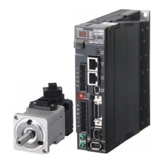
1-3 Names and Functions 1-3 Names and Functions Servo Drive Part Names Display Analog monitor connector (CN5) Operation area USB connector (CN7) Expansion connector (CN3) Main circuit power supply terminals Safety connector (CN8) (L1, L2, and L3) Control circuit power supply terminals (L1C and L2C) Charge lamp Control I/O connector (CN1) -
Page 27: Servo Drive Functions
1-3 Names and Functions Servo Drive Functions Display A 6-digit 7-segment LED display shows the drive status, alarm codes, parameters, and other information. Operation Area Monitors the parameter setting and drive condition. Charge Lamp Lights when the main circuit power supply is turned ON. Control I/O Connector (CN1) Used for command input signals and I/O signals. -
Page 28: System Block Diagrams
1-4 System Block Diagrams 1-4 System Block Diagrams R88D-KTA5L/-KT01L/-KT02L/-KT01H/-KT02H/-KT04H CN A CN B FUSE FUSE Voltage detection FUSE SW power 15 V Relay Regeneration Overcurrent Current detection supply main Gate drive drive control detection circuit control 3.3 V Display and 2.5 V Internal setting circuit... - Page 29 1-4 System Block Diagrams R88D-KT04L/-KT08H/-KT10H/-KT15H CN B CN A FUSE Internal Regeneration Resistor FUSE − Voltage detection FUSE − SW power 15 V Relay Regeneration Overcurrent Current detection supply main Gate drive drive control detection circuit control 3.3 V Display and Internal 2.5 V setting circuit...
- Page 30 1-4 System Block Diagrams R88D-KT20H CN C CN A FUSE Internal Regeneration Resistor FUSE CN B Voltage detection FUSE SW power Relay Regeneration Overcurrent Current detection Gate drive supply main drive control detection circuit control 3.3V Display and 2.5V Internal setting circuit 1.5V MPU &...
- Page 31 1-4 System Block Diagrams R88D-KT30H/-KT50H FUSE Internal Regeneration Resistor FUSE CN B Voltage detection FUSE SW power 15 V Relay Regeneration Overcurrent Current detection supply main Gate drive drive control detection circuit control 3.3 V Display and 2.5 V Internal setting circuit 1.5 V MPU &...
- Page 32 1-4 System Block Diagrams R88D-KT75H FUSE Fuse FUSE Voltage detection FUSE SW power 15 V Relay Regeneration Overcurrent Current detection supply main Gate drive drive control detection circuit control 3.3 V Display and Internal 2.5 V setting circuit MPU & ASIC 1.5 V control power area...
- Page 33 1-4 System Block Diagrams R88D-KT150H FUSE Fuse FUSE Voltage detection FUSE SW power 15 V Relay Regeneration Current detection Overcurrent supply main Gate drive drive control detection circuit control 3.3 V Display and Internal 2.5 V setting circuit MPU & ASIC 1.5 V control power area...
- Page 34 1-4 System Block Diagrams R88D-KT06F/-KT10F/-KT15F/-KT20F FUSE Internal Regeneration Resistor FUSE Voltage detection FUSE 24 V DC-DC SW power 15 V Relay Regeneration Overcurrent Current detection Gate drive supply main drive control detection circuit control 3.3 V Display and Internal 2.5 V setting circuit 1.5 V MPU &...
- Page 35 1-4 System Block Diagrams R88D-KT30F/-KT50F FUSE Internal Regeneration Resistor FUSE Voltage detection FUSE 24 V DC-DC SW power 15 V Relay Regeneration Overcurrent Current detection Gate drive supply main drive control detection circuit control 3.3 V Display and Internal 2.5 V setting circuit 1.5 V MPU &...
- Page 36 1-4 System Block Diagrams R88D-KT75F FUSE Fuse FUSE Voltage detection FUSE 24 V DC-DC SW power 15 V Relay Regeneration Overcurrent Current detection supply main Gate drive drive control detection circuit control 3.3 V Display and Internal 2.5 V setting circuit MPU &...
- Page 37 1-4 System Block Diagrams R88D-KT150F FUSE Fuse FUSE Voltage detection FUSE 24 V DC-DC SW power 15 V Relay Regeneration Overcurrent Current detection supply main Gate drive drive control detection circuit control 3.3 V Display and Internal 2.5 V setting circuit MPU &...
-
Page 38: Applicable Standards
1-5 Applicable Standards 1-5 Applicable Standards EC Directives Product Applicable standards Directives AC Servo Drive EN 61800-5-1 Voltage AC Servomotor EN60034-1/-5 Directive AC Servo Drive EN 55011 class A group 1 Directives IEC61800-3 EN61000-6-2 Machinery AC Servo Drive EN954-1 (Category 3) Directive EN ISO13849-1: 2008 (Category 3) (PLc,d) ISO13849-1: 2006 (Category 3) (PLc,d) -
Page 39: Korean Radio Regulations (Kc)
1-5 Applicable Standards The Servo Drives and Servomotors comply with UL 508C (file No. E179149) as long as the following installation conditions 1 and 2 are met. (1) Use the Servo Drive in a pollution degree 1 or 2 environment as defined in IEC 60664- 1 (example: installation in an IP54 control panel). -
Page 40: Semi F47
1-5 Applicable Standards SEMI F47 Some Servo Drives conform to the SEMI F47 standard for momentary power interruptions (voltage sag immunity) for no-load or light-load operation. This standard applies to semiconductor manufacturing equipment. Note 1. It does not apply to Servo Drivers with single-phase 100-V specifications or with 24-VDC specifications for the control power input. -
Page 41: Unit Versions
1-6 Unit Versions 1-6 Unit Versions The G5-series Servo Drive uses unit versions. Unit versions are used to manage differences in supported functions when product upgrades are made. Confirmation Method The unit version of a G5-series Servo Drive is given on the product’s nameplate as shown below. - Page 43 Standard Models and External Dimensions This chapter explains the models of Servo Drives, Servomotors, and peripheral equipment, and provides the external dimensions and mounting dimensions. 2-1 Servo System Configuration ........2-1 2-2 How to Read Model Numbers ........2-3 Servo Drive ..................2-3 Servomotor ..................
-
Page 44: Servo System Configuration
2-1 Servo System Configuration 2-1 Servo System Configuration Support Software Support Software • • CX-One FA Integrated CX-One FA Integrated Controller Tool Package Tool Package Including CX-Programmer (Including CX-Drive) and CX-Position • CX-Drive and CX-Motion WS02-DRVC1 High-speed type NC414 SYNC ERC ERH SYSMAC CJ2H... - Page 45 2-1 Servo System Configuration AC Servomotors AC Servo Drive communications Motor power signals Power Cables • Flexible Cables • Without Brake R88A-CA@@@@@SR-E • With Brake R88A-CA@@@@@BR-E Brake Cables (50 to 750 W max.) • Flexible Cables R88A-CAKA@@@BR-E • • OMNUC G5 Series Servo Drive OMNUC G5-series Servomotor Feedback Signals R88D-KT...
-
Page 46: How To Read Model Numbers
2-2 How to Read Model Numbers 2-2 How to Read Model Numbers Servo Drive The Servo Drive model number tells the Servo Drive type, applicable Servomotor capacity, power supply voltage, etc. R88D-KT01H OMNUC G5-series Servo Drive Drive Type : Pulse/analog type Maximum Applicable Servomotor Capacity : 50 W : 100 W... -
Page 47: Servomotor
2-2 How to Read Model Numbers Servomotor R88M-K10030H-BOS2 OMNUC G5-series Servomotor Servomotor Capacity : 50 W : 100 W : 200 W : 400 W : 600 W : 750 W : 900 W : 1 kW : 1.5 kW : 2 kW : 3 kW : 4 kW... -
Page 48: Standard Model Tables
2-3 Standard Model Tables 2-3 Standard Model Tables Servo Drive Model Table Specifications Model Single-phase 100 VAC 50 W R88D-KTA5L 100 W R88D-KT01L 200 W R88D-KT02L 400 W R88D-KT04L Single-phase/3-phase 200 VAC 100 W R88D-KT01H 200 W R88D-KT02H 400 W R88D-KT04H 750 W R88D-KT08H... -
Page 49: Servomotor Model Tables
2-3 Standard Model Tables Servomotor Model Tables 3,000-r/min Servomotors Model With incremental encoder With absolute encoder Specifications Straight shaft Straight shaft Straight shaft Straight shaft without key with key and tap without key with key and tap 50 W R88M-K05030H R88M-K05030H-S2 R88M-K05030T R88M-K05030T-S2... - Page 50 2-3 Standard Model Tables Model With incremental encoder With absolute encoder Specifications Straight shaft Straight shaft Straight shaft Straight shaft without key with key and tap without key with key and tap 50 W R88M-K05030H-B R88M-K05030H-BS2 R88M-K05030T-B R88M-K05030T-BS2 100 W R88M-K10030L-B R88M-K10030L-BS2 R88M-K10030S-B R88M-K10030S-BS2...
- Page 51 2-3 Standard Model Tables 1,500-r/min and 2,000-r/min Servomotors Model With incremental encoder With absolute encoder Specifications Straight shaft Straight shaft Straight shaft Straight shaft without key with key and tap without key with key and tap 1 kW R88M-K1K020H R88M-K1K020H-S2 R88M-K1K020T R88M-K1K020T-S2 1.5 kW R88M-K1K520H...
- Page 52 2-3 Standard Model Tables Model With incremental encoder With absolute encoder Specifications Straight shaft Straight shaft Straight shaft Straight shaft without key with key and tap without key with key and tap 1 kW R88M-K1K020H-B R88M-K1K020H-BS2 R88M-K1K020T-B R88M-K1K020T-BS2 1.5 kW R88M-K1K520H-B R88M-K1K520H-BS2 R88M-K1K520T-B R88M-K1K520T-BS2...
- Page 53 2-3 Standard Model Tables 1,000-r/min Servomotors Model With incremental encoder With absolute encoder Specifications Straight shaft Straight shaft Straight shaft Straight shaft without key with key and tap without key with key and tap 900 kW R88M-K90010H R88M-K90010H-S2 R88M-K90010T R88M-K90010T-S2 2 kW R88M-K2K010H R88M-K2K010H-S2...
-
Page 54: Servo Drive And Servomotor Combination Tables
2-3 Standard Model Tables Servo Drive and Servomotor Combination Tables The tables in this section show the possible combinations of OMNUC G5-series Servo Drives and Servomotors. The Servomotors and Servo Drives can only be used in the listed combinations. “-@” at the end of the motor model number is for options, such as the shaft type, brake, oil seal and key. - Page 55 2-3 Standard Model Tables 1,500-r/min and 2,000-r/min Servomotors and Servo Drives Servomotor Voltage Servo Drive Rated With incremental With absolute output encoder encoder 1 kW R88M-K1K020H-@ R88M-K1K020T-@ R88D-KT10H Single-phase/ 3-phase 200 V 1.5 kW R88M-K1K520H-@ R88M-K1K520T-@ R88D-KT15H 2 kW R88M-K2K020H-@ R88M-K2K020T-@ R88D-KT20H 3 kW...
-
Page 56: Peripheral Equipment And Cable Model Tables
2-3 Standard Model Tables 1,000-r/min Servomotors and Servo Drives Servomotor Voltage Servo Drive Rated With incremental With absolute encoder output encoder Single-phase/ 900 W* R88M-K90010H-@ R88M-K90010T-@ R88D-KT15H 3-phase 200 V 2 kW* R88M-K2K010H-@ R88M-K2K010T-@ R88D-KT30H 3 kW* R88M-K3K010H-@ R88M-K3K010T-@ R88D-KT50H 3-phase 200 V 4.5 kW* R88M-K4K510T-@... - Page 57 2-3 Standard Model Tables Motor Power Cables (European Flexible Cables) Model Specifications For motor without brake For motor with brake [100 V and 200 V] 1.5 m R88A-CAKA001-5SR-E For 3,000-r/min Servomotors of 50 to R88A-CAKA003SR-E 750 W R88A-CAKA005SR-E (See note 1.) 10 m R88A-CAKA010SR-E 15 m...
- Page 58 2-3 Standard Model Tables Brake Cables (European Flexible Cables) Specifications Model [100 V and 200 V] 1.5 m R88A-CAKA001-5BR-E For 3,000-r/min Servomotors of 50 to 750 W R88A-CAKA003BR-E R88A-CAKA005BR-E 10 m R88A-CAKA010BR-E 15 m R88A-CAKA015BR-E 20 m R88A-CAKA020BR-E Note: For flexible brake cables for Servomotors of 6 to 15 kW, refer to 3-4 Cable and Connector Specifications and make your own brake cable.
- Page 59 2-3 Standard Model Tables Motor Power Cables (Global Non-Flexible Cables) Model Specifications For motor without For motor with brake brake [100 V and 200 V] R88A-CAKA003S (See note 1.) For 3,000-r/min Servomotors of 50 to 750 R88A-CAKA005S 10 m R88A-CAKA010S 15 m R88A-CAKA015S 20 m...
- Page 60 2-3 Standard Model Tables Model Specifications For motor without For motor with brake brake For 2,000-r/min Servomotors of 7.5 kW R88A-CAGE003S For 1,000-r/min Servomotors of 6 kW R88A-CAGE005S 10 m R88A-CAGE010S 15 m R88A-CAGE015S 20 m R88A-CAGE020S 30 m R88A-CAGE030S 40 m R88A-CAGE040S 50 m...
- Page 61 2-3 Standard Model Tables Encoder Cables (Global Flexible Cables) Specifications Model [100 V and 200 V] R88A-CRKA003CR For 3,000-r/min Servomotors of 50 to 750 W R88A-CRKA005CR (for both absolute encoders and incremental encoders) 10 m R88A-CRKA010CR 15 m R88A-CRKA015CR 20 m R88A-CRKA020CR 30 m R88A-CRKA030CR...
- Page 62 2-3 Standard Model Tables Model Specifications For motor without For motor with brake brake [400 V] R88A-CAGB003SR R88A-CAKF003BR For 3,000-r/min Servomotors of 750 W to R88A-CAGB005SR R88A-CAKF005BR 2 kW For 2,000-r/min Servomotors of 400 W to 10 m R88A-CAGB010SR R88A-CAKF010BR 2 kW 15 m R88A-CAGB015SR...
- Page 63 2-3 Standard Model Tables Absolute Encoder Battery Cables Specifications Model Absolute Encoder Battery Cable (battery not supplied) 0.3 m R88A-CRGD0R3C Absolute Encoder Battery Cable (R88A-BAT01G battery × 1 supplied) 0.3 m R88A-CRGD0R3C-BS Absolute Encoder Backup Battery Specifications Model 2,000 mA•h 3.6 V R88A-BAT01G Analog Monitor Cable Specifications...
- Page 64 2-3 Standard Model Tables Servo Relay Units (for CN1) Specifications Model Servo Relay Unit For CS1W-NC113/-NC133 XW2B-20J6-1B For CJ1W-NC113/-NC133 For C200HW-NC113 For CS1W-NC213/-NC413/-NC233/-NC433 XW2B-40J6-2B For CJ1W-NC213/-NC413/-NC233/-NC433 For C200HW-NC213/-NC413 For CJ1M-CPU21/-CPU22/-CPU23 XW2B-20J6-8A XW2B-40J6-9A For CQM1-CPU43-V1 XW2B-20J6-3B For CQM1H-PLB21 Servo Relay Unit Cables for Servo Drives Specifications Model Servo Drive cables...
- Page 65 2-3 Standard Model Tables Servo Relay Unit Cables for Position Control Units Specifications Model For CQM1H-PLB21 (XW2B-20J6-3B) 0.5 m XW2Z-050J-A3 XW2Z-100J-A3 For CS1W-NC113, C200HW-NC113 (XW2B- 0.5 m XW2Z-050J-A6 20J6-1B) XW2Z-100J-A6 For CS1W-NC213/-NC413, C200HW-NC213/- 0.5 m XW2Z-050J-A7 NC413 (XW2B-20J6-2B) XW2Z-100J-A7 For CS1W-NC133 (XW2B-20J6-1B) 0.5 m XW2Z-050J-A10 XW2Z-100J-A10...
- Page 66 2-3 Standard Model Tables Control Cables Specifications Model Specified cables for Position Control Unit XW2Z-100J-G9 (line-driver output for 1 axis) XW2Z-500J-G9 CJ1W-NC234/-NC434 10 m XW2Z-10MJ-G9 Specified cables for Position Control Unit XW2Z-100J-G13 (open collector output for 1 axis) XW2Z-300J-G13 CJ1W-NC214/-NC414 Specified cables for Position Control Unit XW2Z-100J-G1 (line-driver output for 2 axes)
- Page 67 2-3 Standard Model Tables Mounting Brackets (L-Brackets for Rack Mounting) Specifications Model R88D-KTA5L/-KT01L/-KT01H/-KT02H R88A-TK01K R88D-KT02L/-KT04H R88A-TK02K R88D-KT04L/-KT08H R88A-TK03K R88D-KT10H/-KT15H/-KT06F/-KT10F/-KT15F R88A-TK04K OMNUC G5-SERIES AC SERVOMOTOR AND SERVO DRIVE USER'S MANUAL 2-24...
-
Page 68: External And Mounting Dimensions
2-4 External and Mounting Dimensions 2-4 External and Mounting Dimensions Servo Drive Dimensions Single-phase 100 VAC: R88D-KTA5L/-KT01L (50 to 100 W) Single-phase/3-phase 200 VAC: R88D-KT01H/-KT02H (100 to 200 W) Wall Mounting External dimensions Mounting dimensions 2-M4 2-25 OMNUC G5-SERIES AC SERVOMOTOR AND SERVO DRIVE USER'S MANUAL... - Page 69 2-4 External and Mounting Dimensions Front Mounting (Using Front Mounting Brackets) External dimensions Mounting dimensions 19.5 φ5.2 2-M4 Rectangular hole (42)* * Rectangular hole dimensions are reference values. OMNUC G5-SERIES AC SERVOMOTOR AND SERVO DRIVE USER'S MANUAL 2-26...
- Page 70 2-4 External and Mounting Dimensions Single-phase/3-phase 100 VAC: R88D-KT02L (200 W) Single-phase/3-phase 200 VAC: R88D-KT04H (400 W) Wall Mounting External dimensions Mounting dimensions 2-M4 Front Mounting (Using Front Mounting Brackets) External dimensions Mounting dimensions 19.5 2-M4 φ5.2 Rectangular hole R2.6 (57)* * Rectangular hole dimensions are reference values.
- Page 71 2-4 External and Mounting Dimensions Single-phase/3-phase 100 VAC: R88D-KT04L (400 W) Single-phase/3-phase 200 VAC: R88D-KT08H (750 W) Wall Mounting External dimensions Mounting dimensions 2-M4 Front Mounting (Using Front Mounting Brackets) External dimensions Mounting dimensions 19.5 2-M4 φ5.2 Rectangular hole R2.6 (67)* * Rectangular hole dimensions are reference values.
- Page 72 2-4 External and Mounting Dimensions Single-phase/3-phase 200 VAC: R88D-KT10H/-KT15H (900 W to 1.5 kW) Wall Mounting External dimensions Mounting dimensions 2-M4 Front Mounting (Using Front Mounting Brackets) External dimensions Mounting dimensions 19.5 4-M4 φ5.2 φ5.2 Rectangular hole R2.6 R2.6 (88)* * Rectangular hole dimensions are reference values.
- Page 73 2-4 External and Mounting Dimensions 3-phase 200 VAC: R88D-KT20H (2 kW) Wall Mounting External dimensions 193.5 17.5 φ5.2 42.5 R2.6 R2.6 R2.6 R2.6 φ5.2 42.5 17.5 Mounting dimensions 6-M4 18.5 OMNUC G5-SERIES AC SERVOMOTOR AND SERVO DRIVE USER'S MANUAL 2-30...
- Page 74 2-4 External and Mounting Dimensions Front Mounting (Using Front Mounting Brackets) External dimensions 193.5 17.5 φ5.2 42.5 30.7 R2.6 R2.6 R2.6 R2.6 φ5.2 42.5 17.5 Mounting dimensions 6-M4 Rectangular hole 19.5 (88)* * Rectangular hole dimensions are reference values. 2-31 OMNUC G5-SERIES AC SERVOMOTOR AND SERVO DRIVE USER'S MANUAL...
- Page 75 2-4 External and Mounting Dimensions 3-phase 200 VAC: R88D-KT30H/-KT50H (3 to 5 kW) Wall Mounting External dimensions φ5.2 R2.6 R2.6 R2.6 R2.6 φ5.2 Mounting dimensions 6-M4 OMNUC G5-SERIES AC SERVOMOTOR AND SERVO DRIVE USER'S MANUAL 2-32...
- Page 76 2-4 External and Mounting Dimensions Front Mounting (Using Front Mounting Brackets) External dimensions φ5.2 40.7 R2.6 R2.6 R2.6 R2.6 φ5.2 Mounting dimensions 6-M4 Rectangular hole (132)* * Rectangular hole dimensions are reference values. 2-33 OMNUC G5-SERIES AC SERVOMOTOR AND SERVO DRIVE USER'S MANUAL...
- Page 77 2-4 External and Mounting Dimensions 3-phase 200 VAC: R88D-KT75H (7.5 kW) Wall Mounting External dimensions φ φ R2.6 R2.6 R2.6 φ R2.6 R2.6 R2.6 φ Mounting dimensions 10-M4 OMNUC G5-SERIES AC SERVOMOTOR AND SERVO DRIVE USER'S MANUAL 2-34...
- Page 78 2-4 External and Mounting Dimensions Front Mounting (Using Front Mounting Brackets) External dimensions φ φ R2.6 R2.6 R2.6 φ R2.6 R2.6 R2.6 φ Mounting dimensions 10-M4 Rectangular hole 27.8 (235)* * Rectangular hole dimensions are reference values. 2-35 OMNUC G5-SERIES AC SERVOMOTOR AND SERVO DRIVE USER'S MANUAL...
- Page 79 2-4 External and Mounting Dimensions 3-phase 200 VAC: R88D-KT150H (15 kW) Wall Mounting External dimensions φ φ 30.5 R3.5 R3.5 30.5 Mounting dimensions 30.5 4-M6 OMNUC G5-SERIES AC SERVOMOTOR AND SERVO DRIVE USER'S MANUAL 2-36...
- Page 80 2-4 External and Mounting Dimensions 3-phase 400 VAC: R88D-KT06F/-KT10F/-KT15F (600 W to 1.5 kW) Wall Mounting External dimensions Mounting dimensions 2-M4 14.5 Front Mounting (Using Front Mounting Brackets) External dimensions Mounting dimensions 19.5 4-M4 φ5.2 φ5.2 Rectangular hole R2.6 (94)* * Rectangular hole dimensions are reference values.
- Page 81 2-4 External and Mounting Dimensions 3-phase 400 VAC: R88D-KT20F (2 kW) Wall Mounting External dimensions Mounting dimensions 17.5 φ5.2 42.5 193.5 6-M4 R2.6 R2.6 26.5 φ5.2 17.5 Front Mounting (Using Front Mounting Brackets) External dimensions Mounting dimensions 193.5 17.5 φ5.2 30.7 42.5 6-M4...
- Page 82 2-4 External and Mounting Dimensions 3-phase 400 VAC: R88D-KT30F/-KT50F (3 to 5 kW) Wall Mounting External dimensions Mounting dimensions 6-M4 φ5.2 R2.6 R2.6 φ5.2 Front Mounting (Using Front Mounting Brackets) External dimensions Mounting dimensions 6-M4 φ5.2 40.7 Rectangular hole R2.6 (132)* R2.6 φ5.2...
- Page 83 2-4 External and Mounting Dimensions 3-phase 400 VAC: R88D-KT75F (7.5 kW) Wall Mounting External dimensions φ φ R2.6 R2.6 R2.6 φ R2.6 R2.6 R2.6 φ Mounting dimensions 10-M4 OMNUC G5-SERIES AC SERVOMOTOR AND SERVO DRIVE USER'S MANUAL 2-40...
- Page 84 2-4 External and Mounting Dimensions Front Mounting (Using Front Mounting Brackets) External dimensions φ φ R2.6 R2.6 R2.6 R2.6 φ R2.6 R2.6 φ Mounting dimensions 10-M4 Rectangular hole 27.8 (235)* * Rectangular hole dimensions are reference values. 2-41 OMNUC G5-SERIES AC SERVOMOTOR AND SERVO DRIVE USER'S MANUAL...
- Page 85 2-4 External and Mounting Dimensions 3-phase 400 VAC: R88D-KT150F (15 kW) Wall Mounting External dimensions φ φ 30.5 R3.5 R3.5 30.5 Mounting dimensions 30.5 4-M6 OMNUC G5-SERIES AC SERVOMOTOR AND SERVO DRIVE USER'S MANUAL 2-42...
-
Page 86: Servomotor Dimensions
2-4 External and Mounting Dimensions Servomotor Dimensions 3,000-r/min Servomotors (100 V and 200 V) 50 W/100 W (without Brake) R88M-K05030H (-S2)/-K10030L (-S2) R88M-K05030T (-S2)/-K10030S (-S2) Encoder connector Motor connector 40×40 (Shaft end specifications with key and tap) 12.5 (Key groove P9) R3.7 M3 (depth 6) 1.5 min. - Page 87 2-4 External and Mounting Dimensions 50 W/100 W (with Brake) R88M-K05030H-B (S2)/-K10030L-B (S2) R88M-K05030T-B (S2)/-K10030S-B (S2) Encoder connector Brake connector Motor connector 40×40 (Shaft end specifications with key and tap) 12.5 (Key groove P9) R3.7 M3 (depth 6) 1.5 min. Boss insertion position R4.2 (only for the ones with oil seal)
- Page 88 2-4 External and Mounting Dimensions 200 W/400 W (without Brake) R88M-K20030@ (-S2)/-K40030@ (-S2) R88M-K20030@ (-S2)/-K40030@ (-S2) Encoder connector Motor connector 60×60 (Shaft end specifications with key and tap) 4−φ4.5 30 20 (200 W) 25 (400 W) 4h9 (200 W) 18 (200 W) 5h9 (400 W) 22.5 (400 W) (Key groove P9)
- Page 89 2-4 External and Mounting Dimensions 750 W (without Brake) R88M-K75030H (-S2) R88M-K75030T (-S2) Encoder connector Motor connector 112.2 86.2 80×80 (Shaft end specifications with key and tap) 4−φ6 M5 (depth 10) Note. The standard models have a straight shaft. Models with a key and tap are indicated with S2 at the end of the model number.
- Page 90 2-4 External and Mounting Dimensions 1 kW/1.5 kW/2 kW (without Brake) R88M-K1K030H (-S2)/-K1K530H (-S2)/-K2K030H (-S2) R88M-K1K030T (-S2)/-K1K530T (-S2)/-K2K030T (-S2) 1 kW/1.5 kW/2 kW (with Brake) R88M-K1K030H-B (S2)/-K1K530H-B (S2)/-K2K030H-B (S2) R88M-K1K030T-B (S2)/-K1K530T-B (S2)/-K2K030T-B (S2) Motor and brake connector (Shaft end specifications with key and tap) Encoder 100100 connector...
- Page 91 2-4 External and Mounting Dimensions 3 kW (without Brake) R88M-K3K030H (-S2) R88M-K3K030T (-S2) 3 kW (with Brake) R88M-K3K030H-B (S2) R88M-K3K030T-B (S2) Motor and brake connector (Shaft end specifications with key and tap) 120120 Encoder connector 49 M3, through M5 (depth 12) Dimensions (mm) Model R88M-K3K030@...
- Page 92 2-4 External and Mounting Dimensions 4 kW/5 kW (without Brake) R88M-K4K030H (-S2)/-K5K030H (-S2) R88M-K4K030T (-S2)/-K5K030T (-S2) 4 kW/5 kW (with Brake) R88M-K4K030H-B (S2)/-K5K030H-B (S2) R88M-K4K030T-B (S2)/-K5K030T-B (S2) Motor and brake connector (Shaft end specifications with key and tap) Encoder 130130 connector 49 M3, through...
- Page 93 2-4 External and Mounting Dimensions 3,000-r/min Servomotors (400 V) 750 W/1 kW/1.5 kW/2 kW (without Brake) R88M-K75030F (-S2)/-K1K030F (-S2)/-K1K530F (-S2)/-K2K030F (-S2) R88M-K75030C (-S2)/-K1K030C (-S2)/-K1K530C (-S2)/-K2K030C (-S2) 750 W/1 kW/1.5 kW/2 kW (with Brake) R88M-K75030F-B (S2)/-K1K030F-B (S2)/-K1K530F-B (S2)/-K2K030F-B (S2) R88M-K75030C-B (S2)/-K1K030C-B (S2)/-K1K530C-B (S2)/-K2K030C-B (S2) Motor and brake connector Encoder...
- Page 94 2-4 External and Mounting Dimensions 3 kW (without Brake) R88M-K3K030F (-S2) R88M-K3K030C (-S2) 3 kW (with Brake) R88M-K3K030F-B (S2) R88M-K3K030C-B (S2) Motor and brake connector (Shaft end specifications with key and tap) 120120 Encoder connector 4-9 M3, through M5 (depth 12) Dimensions (mm) Model R88M-K3K030@...
- Page 95 2-4 External and Mounting Dimensions 4 kW/5 kW (without Brake) R88M-K4K030F (-S2)/-K5K030F (-S2) R88M-K4K030C (-S2)/-K5K030C (-S2) 4 kW/5 kW (with Brake) R88M-K4K030F-B (S2)/-K5K030F-B (S2) R88M-K4K030C-B (S2)/-K5K030C-B (S2) Motor and brake connector (Shaft end specifications with key and tap) Encoder 130130 connector 49 M3, through...
- Page 96 2-4 External and Mounting Dimensions 1,500-r/min and 2,000-r/min Servomotors (200 V) 1 kW/1.5 kW/2 kW/3 kW (without Brake) R88M-K1K020H (-S2)/-K1K520H (-S2)/-K2K020H (-S2)/-K3K020H (-S2) R88M-K1K020T (-S2)/-K1K520T (-S2)/-K2K020T (-S2)/-K3K020T (-S2) 1 kW/1.5 kW/2 kW/3 kW (with Brake) R88M-K1K020H-B (S2)/-K1K520H-B (S2)/-K2K020H-B (S2)/-K3K020H-B (S2) R88M-K1K020T-B (S2)/-K1K520T-B (S2)/-K2K020T-B (S2)/-K3K020T-B (S2) Motor and brake connector...
- Page 97 2-4 External and Mounting Dimensions 4 kW/5 kW (without Brake) R88M-K4K020H (-S2)/-K5K020H (-S2) R88M-K4K020T (-S2)/-K5K020T (-S2) 4 kW/5 kW (with Brake) R88M-K4K020H-B (S2)/-K5K020H-B (S2) R88M-K4K020T-B (S2)/-K5K020T-B (S2) Motor and brake connector (Shaft end specifications with key and tap) 176176 Encoder connector 413.5 M3, through...
- Page 98 2-4 External and Mounting Dimensions 7.5 kW (without Brake) R88M-K7K515T (-S2) 7.5 kW (with Brake) R88M-K7K515T-B (S2) Motor connector Brake connector (for model with brake only) 176 × 176 Encoder connector 43.5 43.5 (Shaft end specifications with key and tap) 4-φ13.5 M4, through 12h9...
- Page 99 2-4 External and Mounting Dimensions 11 kW/15 kW (without Brake) R88M-K11K015T (-S2)/-K15K015T (-S2) 11 kW/15 kW (with Brake) R88M-K11K015T-B (S2)/R88M-K15K015T-B (S2) Motor Brake connector connector (for model with brake only) 220 × 220 Encoder connector 4-φ13.5 (Shaft end specifications with key and tap) 16h9 through (Key groove P9)
- Page 100 2-4 External and Mounting Dimensions 1,500-r/min and 2,000-r/min Servomotors (400 V) 400 W/600 W (without Brake) R88M-K40020F (-S2)/-K60020F (-S2) R88M-K40020C (-S2)/-K60020C (-S2) 400 W/600 W (with Brake) R88M-K40020F-B (S2)/-K60020F-B (S2) R88M-K40020C-B (S2)/-K60020C-B (S2) Motor and brake connector Encoder connector 100100 (Shaft end specifications with key and tap) M3, through 49...
- Page 101 2-4 External and Mounting Dimensions 1 kW/1.5 kW/2 kW/3 kW (without Brake) R88M-K1K020F (-S2)/-K1K520F (-S2)/-K2K020F (-S2)/-K3K020F (-S2) R88M-K1K020C (-S2)/-K1K520C (-S2)/-K2K020C (-S2)/-K3K020C (-S2) 1 kW/1.5 kW/2 kW/3 kW (with Brake) R88M-K1K020F-B (S2)/-K1K520F-B (S2)/-K2K020F-B (S2)/-K3K020F-B (S2) R88M-K1K020C-B (S2)/-K1K520C-B (S2)/-K2K020C-B (S2)/-K3K020C-B (S2) Motor and brake connector (Shaft end specifications with key and tap) 130130...
- Page 102 2-4 External and Mounting Dimensions 4 kW/5 kW (without Brake) R88M-K4K020F (-S2)/-K5K020F (-S2) R88M-K4K020C (-S2)/-K5K020C (-S2) 4 kW/5 kW (with Brake) R88M-K4K020F-B (S2)/-K5K020F-B (S2) R88M-K4K020C-B (S2)/-K5K020C-B (S2) Motor and brake connector Encoder 176176 (Shaft end specifications with key and tap) connector 4-13.5 M3, through...
- Page 103 2-4 External and Mounting Dimensions 7.5 kW (without Brake) R88M-K7K515C (-S2) 7.5 kW (with Brake) R88M-K7K515C-B (S2) Motor Brake connector connector (for model with brake only) Encoder 176 × 176 connector 43.5 43.5 (Shaft end specifications with key and tap) 4-φ13.5 M4, through 12h9...
- Page 104 2-4 External and Mounting Dimensions 11 kW/15 kW (without Brake) R88M-K11K015C (-S2)/-K15K015C (-S2) 11 kW/15 kW (with Brake) R88M-K11K015C-B (S2)/R88M-K15K015C-B (S2) Brake connector Motor (for model with brake only) connector 220 × 220 Encoder connector 4-φ13.5 (Shaft end specifications with key and tap) 16h9 through (Key groove P9)
- Page 105 2-4 External and Mounting Dimensions 1,000-r/min Servomotors (200 V) 900 W (without Brake) R88M-K90010H (-S2) R88M-K90010T (-S2) 900 W (with Brake) R88M-K90010H-B (S2) R88M-K90010T-B (S2) Motor and brake connector Encoder 130130 (Shaft end specifications with key and tap) connector 77.5 4-ø9 M3, through M5 (depth 12)
- Page 106 2-4 External and Mounting Dimensions 2 kW/3 kW (without Brake) R88M-K2K010H (-S2)/-K3K010H (-S2) R88M-K2K010T (-S2)/-K3K010T (-S2) 2 kW/3 kW (with Brake) R88M-K2K010H-B (S2)/-K3K010H-B (S2) R88M/-K2K010T-B (S2)/-K3K010T-B (S2) Motor and brake connector 176176 Encoder (Shaft end specifications with key and tap) connector 413.5 M3, through...
- Page 107 2-4 External and Mounting Dimensions 4.5 kW (without Brake) R88M-K4K510T (-S2) 4.5 kW (with Brake) R88M-K4K510T-B (S2) 176 × 176 Motor and brake connector 43.5 43.5 Encoder connector (Shaft end specifications with key and tap) 4-φ13.5 M4, through 12h9 (Key groove P9) 2 min.
- Page 108 2-4 External and Mounting Dimensions 6 kW (without Brake) R88M-K6K010T (-S2) 6 kW (with Brake) R88M-K6K010T-B (S2) Motor connector Brake connector (for model with brake only) Encoder 176 × 176 connector 43.5 43.5 (Shaft end specifications with key and tap) 4-φ13.5 M4, through 12h9...
- Page 109 2-4 External and Mounting Dimensions 1,000-r/min Servomotors (400 V) 900 W (without Brake) R88M-K90010F (-S2) R88M-K90010C (-S2) 900 W (with Brake) R88M-K90010F-B (S2) R88M-K90010C-B (S2) Motor and brake connector Encoder 130130 (Shaft end specifications with key and tap) connector 4-ø9 M3, through M5 (depth 10) Dimensions (mm)
- Page 110 2-4 External and Mounting Dimensions 2 kW/3 kW (without Brake) R88M-K2K010F (-S2)/-K3K010F (-S2) R88M-K2K010C (-S2)/-K3K010C (-S2) 2 kW/3 kW (with Brake) R88M-K2K010F-B (S2)/-K3K010F-B (S2) R88M-K2K010C-B (S2)/-K3K010C-B (S2) Motor and brake connector (Shaft end specifications with key and tap) Encoder 176176 connector 413.5 M3, through...
- Page 111 2-4 External and Mounting Dimensions 4.5 kW (without Brake) R88M-K4K510C (-S2) 4.5 kW (with Brake) R88M-K4K510C-B (S2) 176 × 176 Motor and brake connector 43.5 43.5 Encoder connector (Shaft end specifications with key and tap) 4-φ13.5 M4, through 12h9 (Key groove P9) 2 min.
- Page 112 2-4 External and Mounting Dimensions 6 kW (without Brake) R88M-K6K010C (-S2) 6 kW (with Brake) R88M-K6K010C-B (S2) Motor connector Brake connector (for model with brake only) 176 × 176 Encoder connector 43.5 43.5 (Shaft end specifications with key and tap) 4-φ13.5 M4, through 12h9...
-
Page 113: External Regeneration Resistor Dimensions
2-4 External and Mounting Dimensions External Regeneration Resistor Dimensions R88A-RR08050S/-RR080100S Thermal switch output R88A-RR22047S1 Thermal switch output R88A-RR50020S 43 25 OMNUC G5-SERIES AC SERVOMOTOR AND SERVO DRIVE USER'S MANUAL 2-70... -
Page 114: Emc Filter Dimensions
2-5 EMC Filter Dimensions 2-5 EMC Filter Dimensions drive mounts output flexes External dimensions Mount dimensions Filter model R88A-FIK102-RE R88A-FIK104-RE R88A-FIK107-RE R88A-FIK114-RE R88A-FIK304-RE R88A-FIK306-RE R88A-FIK312-RE 2-71 OMNUC G5-SERIES AC SERVOMOTOR AND SERVO DRIVE USER'S MANUAL... -
Page 115: Dimensions Of Mounting Brackets (L-Brackets For Rack Mounting)
2-6 Dimensions of Mounting Brackets (L-Brackets for Rack Mounting) 2-6 Dimensions of Mounting Brackets (L-Brackets for Rack Mounting) R88A-TK01K Top Dimensions Bottom Dimensions Two, M4 countersunk holes Two, M4 countersunk holes 11±0.2 11±0.2 R88A-TK02K Top Dimensions Bottom Dimensions Two, M4 countersunk holes Two, M4 countersunk holes 18±0.2 18±0.2... - Page 116 2-6 Dimensions of Mounting Brackets (L-Brackets for Rack Mounting) R88A-TK04K Top Dimensions Bottom Dimensions Two, M4 countersunk holes Two, M4 countersunk holes 36± 0.2 36± 0.2 40±0.2 40±0.2 2-73 OMNUC G5-SERIES AC SERVOMOTOR AND SERVO DRIVE USER'S MANUAL...
- Page 117 Specifications This chapter provides the general specifications, characteristics, connector specifications, and I/O circuits of the Servo Drives as well as the general specifications, characteristics, encoder specifications of the Servomotors and other peripheral devices. 3-1 Servo Drive Specifications ..........3-1 General Specifications ..............3-1 Characteristics ................
-
Page 118: Servo Drive Specifications
3-1 Servo Drive Specifications 3-1 Servo Drive Specifications Select a Servo Drive that matches the Servomotor to be used. Refer to "Servo Drive and Servomotor Combination Tables"(P.2-11). The same OMNUC G5-Series AC Servo Drive can be used for either a pulse train input or analog input. -
Page 119: Characteristics
3-1 Servo Drive Specifications Characteristics 100-VAC Input Models Item R88D-KTA5L R88D-KT01L R88D-KT02L R88D-KT04L Continuous output current (rms) 1.2 A 1.7 A 2.5 A 4.6 A Input power Main Power supply circuit supply 0.4 KVA 0.4 KVA 0.5 KVA 0.9 KVA capacity Power supply... - Page 120 3-1 Servo Drive Specifications 200-VAC Input Models R88D- R88D- R88D- R88D- R88D- R88D- Item KT01H KT02H KT04H KT08H KT10H KT15H Continuous output current (rms) 1.2 A 1.6 A 2.6 A 4.1 A 5.9 A 9.4 A Input power Main Power supply circuit supply...
- Page 121 3-1 Servo Drive Specifications R88D- R88D- R88D- R88D- R88D- Item KT20H KT30H KT50H KT75H KT150H Continuous output current (rms) 13.4 A 18.7 A 33.0 A 44.0 A 66.1 A Input power Main Power supply 3.3 KVA 4.5 KVA 7.5 KVA 11.0 KVA 22.0 KVA supply...
- Page 122 3-1 Servo Drive Specifications 400-VAC Input Models Item R88D-KT06F R88D-KT10F R88D-KT15F R88D-KT20F Continuous output current (rms) 1.5 A 2.9 A 4.7 A 6.7 A Main circuit Power supply 1.2 KVA 1.8 KVA 2.3 KVA 3.8 KVA capacity Power supply 3-phase 380 to 480 VAC (323 to 528 V) 50/60 Hz voltage Input power Rated current...
- Page 123 3-1 Servo Drive Specifications Item R88D-KT30F R88D-KT50F R88D-KT75F R88D-KT150F Continuous output current (rms) 9.4 A 16.5 A 22.0 A 33.4 A Main circuit Power supply 4.5 KVA 6.0 KVA 11.0 KVA 22.0 KVA capacity Power supply 3-phase 380 to 480 VAC (323 to 528 V) 50/60 Hz voltage Input power Rated current...
- Page 124 3-1 Servo Drive Specifications Protective Functions Error detected Description Control power supply undervoltage The DC voltage of the control power supply fell below the specified value. Overvoltage The DC voltage of the main circuit exceeded the specified value. Main power supply undervoltage The DC voltage of the main circuit is low.
- Page 125 3-1 Servo Drive Specifications Error detected Description The rotation of the absolute encoder is higher than the specified value. Absolute encoder status error Encoder phase-Z error A phase Z pulse was not detected regularly. Encoder CS signal error A logic error was detected in the CS signal. An error was detected in external encoder connection and communications External encoder communications error data.
-
Page 126: Main Circuit And Motor Connections
3-1 Servo Drive Specifications Main Circuit and Motor Connections When wiring the main circuit, use proper wire sizes, grounding systems, and noise resistance. R88D-KTA5L/-KT01L/-KT02L/-KT04L R88D-KT01H/KT02H/-KT04H/-KT08H/-KT10H/-KT15H Main Circuit Connector Specifications (CNA) Symbol Name Function Main circuit power R88D-KT@L supply input (50 to 400 W) : Single-phase 100 to 120 VAC (85 to 132 V) 50/60 Hz R88D-KT@H (100 W to 1.5 kW) : Single-phase: 200 to 240 VAC (170 to 264 V) 50/ 60 Hz... - Page 127 3-1 Servo Drive Specifications R88D-KT20H Main Circuit Connector Specifications (CNA) Symbol Name Function Main circuit power R88D-KT@H (2 kW) : supply input 3-phase: 200 to 230 VAC (170 to 253 V) 50/60 Hz Control circuit power R88D-KT@H : Single-phase 200 to 230 VAC (170 to 253 V) 50/60 supply input Motor Connector Specifications (CNB) Symbol...
- Page 128 3-1 Servo Drive Specifications R88D-KT30H/R88D-KT50H Main Circuit Terminal Block Specifications Symbol Name Function Main circuit power R88D-KT@H (3 to 5 kW): supply input 3-phase 200 to 230 VAC (170 to 253 V) 50/60 Hz Control circuit power R88D-KT@H : Single-phase 200 to 230 VAC (170 to 253 V) 50/60 supply input Normally B2 and B3 are connected.
- Page 129 3-1 Servo Drive Specifications R88D-KT75H Terminal Block Specifications, Left Terminal Block (TB1) Symbol Name Function R88D-KT@H (7.5 kW): 3-phase 200 to 230 VAC (170 to 253 V) 50/ Main circuit power supply 60 Hz input 280 to 325 VDC (238 to 357 VDC) Connect an External Regeneration Resistor between B1 and B2.
- Page 130 3-1 Servo Drive Specifications R88D-KT150H Terminal Block Specifications, Top Terminal Block (TB1) Symbol Name Function R88D-KT@H: Single-phase 200 to 230 VAC (170 to 253 V) 50/60 Control circuit power supply input 280 to 325 VDC (238 to 357 VDC) Dynamic brake These terminals are used to control the MC for externally connected resistance control dynamic brake resistance.
- Page 131 3-1 Servo Drive Specifications R88D-KT06F/R88D-KT10F/R88D-KT15F/R88D-KT20F Main Circuit Connector Specifications (CNA) Symbol Name Function Main circuit power R88D-KT@F supply input (600 W to 2 kW) : 3-phase: 380 to 480 VAC (323 to 528 V) 50/60 Hz Motor Connector Specifications (CNB) Symbol Name Function...
- Page 132 3-1 Servo Drive Specifications R88D-KT30F/R88D-KT50F Main Circuit Terminal Block Specifications (TB1) Symbol Name Function 24 V Control circuit power 24 VDC ± 15% supply input Main Circuit Terminal Block Specifications (TB2) Symbol Name Function Main circuit power supply R88D-KT@F (3 to 5 kW): input 3-phase 380 to 480 VAC (323 to 528 V) 50/60 Hz Normally B2 and B3 are connected.
- Page 133 3-1 Servo Drive Specifications R88D-KT75F Terminal Block Specifications, Left Terminal Block (TB1) Symbol Name Function Main circuit power supply R88D-KT@F (7.5 kW): 3-phase 380 to 480 VAC (323 to 528 V) 50/ input 60 Hz Connect an External Regeneration Resistor between B1 and B2. External Regeneration Resistor connection terminals...
- Page 134 3-1 Servo Drive Specifications R88D-KT150F Terminal Block Specifications, Top Terminal Block (TB1) Symbol Name Function 24 V Control circuit power 24 VDC±15% supply input These terminals are used to control the MC for externally Dynamic brake resistance connected dynamic brake resistance. The output contact control terminals specifications are 1 A max.
-
Page 135: Control I/O Connector Specifications (Cn1)
3-1 Servo Drive Specifications Control I/O Connector Specifications (CN1) Control I/O Signal Connections and External Signal Processing for Position Control +24 VCW 2.2 kΩ Reverse pulse BKIR Maximum Brake interlock −CW 220 Ω service 500 kpps max. BKIRCOM voltage: 30 VDC +24 VCCW 2.2 kΩ... - Page 136 3-1 Servo Drive Specifications Control I/O Signal Connections and External Signal Processing for Speed Control BKIR Speed command 20 kΩ Maximum Brake interlock service voltage: 3.83 kΩ BKIRCOM AGND 30 VDC Servo ready Maximum completed output READY output current: Forward torque limit input 10 kΩ...
- Page 137 3-1 Servo Drive Specifications Control I/O Signal Connections and External Signal Processing for Torque Control Torque command input BKIR or speed limit TREF1/VLIM 20 kΩ Maximum Brake interlock service voltage: 3.83 kΩ BKIRCOM AGND1 30 VDC Servo ready Maximum READY completed output output current: Torque command input...
- Page 138 3-1 Servo Drive Specifications Control I/O Signal List CN1 Control Inputs Control mode Symbol Name Function and interface Fully- number Position Speed Torque closed +24VCW 24-V open-collector Input terminals for position command input for command pulses for both line driver and open +24VCCW pulse collector.
- Page 139 3-1 Servo Drive Specifications Control mode Symbol Name Function and interface Fully- number Position Speed Torque closed Speed limit input Provides a speed limit input (set value: 1) according to the setting of Torque Command/Speed Limit Selection √ VLIM (Pn317). Use the Speed Command Scale (Pn302) to change the limit speed scale for the analog input.
- Page 140 3-1 Servo Drive Specifications Control mode Symbol Name Function and interface Fully- number Position Speed Torque closed Gain switching This changes to enable (set value: 2) according to the setting of the Gain Switching Mode (Pn115 for position control, Pn120 for speed control, or √...
- Page 141 3-1 Servo Drive Specifications Control mode Symbol Name Function and interface Fully- number Position Speed Torque closed Electronic gear You can switch maximum 4 electronic switching 2 gear ratio numerators by combining with √ √ GESEL2 electronic gear switching input 1 (GESEL1).
- Page 142 3-1 Servo Drive Specifications Control mode Symbol Name Function and interface Fully- number Position Speed Torque closed Encoder phase-Z Phase Z is output for encoder signals (or output external encoder signals during fully- √ √ √ √ closed control). Open-collector output Encoder phase-Z ZGND output common...
- Page 143 3-1 Servo Drive Specifications Control mode Symbol Name Function and interface Fully- number Position Speed Torque closed WARN2 Warning output 2 This output turns ON according to the √ √ √ √ setting condition of Warning Output WARN2COM Selection 1 (Pn440). P-CMD Position command This output turns ON when a positioning...
- Page 144 To use an absolute encoder, connect a battery to either Pin 42 which is the backup battery input, or 43 which is the battery holder for absolute encoder cable. (Never connect to both.) Connectors for CN1 (Pin 50) Name Model Manufacturer OMRON model number Cable plug 10150-3000PE Sumitomo 3M R88A-CNU11C Cable case (shell kit)
-
Page 145: Control Input Circuits
3-1 Servo Drive Specifications Control Input Circuits Speed Command Input, Torque Command Input, Speed Limit Input and Torque Limit Input 20 kΩ 47 kΩ 47 kΩ 470pF REF/TREF1/VLIM14 Maximum 1000 pF input voltage ±10 V 1000 pF 47 kΩ 47 kΩ 470 pF 20 kΩ... - Page 146 3-1 Servo Drive Specifications Position Command Pulse (Photocoupler Input) When connecting with a line driver and a photocoupler, the maximum speed will be 500 kpps. (+CW: 3, −CW: 4, +CCW: 5, −CCW: 6) Controller Drive 2.2 kΩ 1000 pF − −...
- Page 147 3-1 Servo Drive Specifications Open Collector Input External 24-V power supply without a Current Limit Resistor (200 kpps maximum) (+24 VCW: 1, −CW: 4, +24 VCCW: 2, −CCW: 6) Controller Drive 2.2 kΩ Vcc 24 V 2.2 kΩ 1000 pF −...
- Page 148 3-1 Servo Drive Specifications General-purpose Input External power supply kΩ +24VIN 12 VDC ± 5% to 24 VDC ± 5% Photocoupler input kΩ Input current specification 10 mA max. (per point) kΩ Signal level kΩ Photocoupler input ON level: 10 V or more OFF level: 3 V or less Minimum ON time 40 ms To another input circuit GND common...
-
Page 149: Control Input Details
3-1 Servo Drive Specifications Control Input Details Details on the input pins for the CN1 connector are described here. High-speed Photocoupler Input Pin 3: +Reverse pulse (+CW), +feed pulse (+PULS), or +phase A (+FA) Pin 4: −Reverse pulse (−CW), −feed pulse (−PULS), or −phase A (−FA) Pin 5: +Forward pulse (+CCW), +direction signal (+SIGN), or +phase B (+FB) Pin 6: −Forward pulse (−CCW), −direction signal (−SIGN), or −phase B (−FB) Function... - Page 150 3-1 Servo Drive Specifications Command Pulse Timing for Photocoupler Inputs Command pulse mode Timing Forward command Reverse command Feed pulse/direction signal Direction signal Maximum input frequency Line driver: 500 kpps Open collector: Feed pulse 200 kpps τ At 200 kpps At 500 kpps t1 ≤...
- Page 151 3-1 Servo Drive Specifications Line Receiver Input Pin 44: +Reverse pulse (+CW), +feed pulse (+PULS), or +phase A (+FA) Pin 45: −Reverse pulse (−CW), −feed pulse (−PULS), or −phase A (−FA) Pin 46: +Forward pulse (+CCW), +direction signal (+SIGN), or +phase B (+FB) Pin 47: −Forward pulse (−CCW), −direction signal (−SIGN), or −phase B (−FB) Function ...
- Page 152 3-1 Servo Drive Specifications Command Pulse Timing for Line Receiver Inputs Command pulse mode Timing Forward command Reverse command Feed pulse/direction signal Direction signal Maximum input frequency Line driver: 4 Mpps Feed pulse τ t 1 ≤ 20 ns t 2 > 125 ns τ...
- Page 153 3-1 Servo Drive Specifications Sensor ON Input (SEN) Pin 20: Sensor ON input (SEN) Pin 13: Signal ground (SENGND) Function This input changes to enable (set value: 1) according to the setting of Absolute Interface Function Selection (Pn616). When the SEN signal turns ON, this performs serial transmission of multi-rotation data of the absolute encoder and also outputs 1-rotation data as the initial incremental pulses.
- Page 154 3-1 Servo Drive Specifications Torque Command Input 2 (TREF2) and Forward Torque Limit Input (PCL) Pin 16: Torque command input 2 (TREF2) and forward torque limit input (PCL) Pin 17: Analog input ground 2 (AGND2) Function During position control, speed control or fully-closed control This signal provides a forward torque limit input (set value: 0 or 4) or forward/reverse torque limit input (set value: 5) according to the setting of Torque Limit Selection (Pn521).
- Page 155 3-1 Servo Drive Specifications Function These two signals are the inputs to prohibit forward and reverse rotation (overtravel inputs). If Drive Prohibition Input Selection (Pn504) is 1, you can use the setting of Stop Selection (Pn505) to select the operation to be taken upon input of each prohibit signal. If Drive Prohibition Input Selection (Pn504) is 2, drive prohibition input protection (E380) actuates upon input of a drive prohibition.
- Page 156 3-1 Servo Drive Specifications Function If the Control mode Selection (Pn001) is set to 3 to 5, the Control mode can be switched as given in the following table. Pn001 set value OFF (first control mode) ON (second control mode) Position control Speed control Position control...
- Page 157 3-1 Servo Drive Specifications Function Use these 2 signals to switch among up to 4 electronic gear ratio numerators. Electronic Electronic Electronic Electronic GESEL1 GESEL2 Gear 1 Gear 2 Gear 3 Gear 4 Pn009 valid Pn500 valid Pn501 valid Pn502 valid ...
- Page 158 3-1 Servo Drive Specifications Function Perform speed control according to the internal speed set value in the parameter. You can select from up to 8 internal speed set values. Pn300 set value VSEL1 VSEL2 VSEL3 Speed command selection − No. 1 Internally Set Speed (Pn304) −...
- Page 159 3-1 Servo Drive Specifications Speed Command Sign Input (VSIGN) No allocation: Speed command sign designation (VSIGN) There is no allocation at default setting. Also, Speed Command Direction Selection (Pn301) is set to disable (set value: 0). You can change the logics and allocations for input terminals (CN1 to 8, 9 and 26 to 33) according to the settings of Input Signal Selection 1 to 10 (Pn400 to 409).
- Page 160 3-1 Servo Drive Specifications Torque Limit Switching (TLSEL) No allocation: Torque Limit Switching (TLSEL) There is no allocation at default setting. You can change the logics and allocations for input terminals (CN1 to 8, 9 and 26 to 33) according to the settings of Input Signal Selection 1 to 10 (Pn400 to 409).
- Page 161 3-1 Servo Drive Specifications Emergency Stop Input (STOP) No allocation: Emergency stop input (STOP) There is no allocation at default setting. You can change the logics and allocations for input terminals (CN1 to 8, 9 and 26 to 33) according to the settings of Input Signal Selection 1 to 10 (Pn400 to 409).
-
Page 162: Control Output Circuits
3-1 Servo Drive Specifications Control Output Circuits Position Feedback Output Servo Drive Controller R = 120 to 180 Ω +5 V Phase A Phase A −A −A Output line driver AM26C31 or equivalent Phase B Phase B −B −B Phase Z Phase Z −Z −Z... -
Page 163: Control Output Details
3-1 Servo Drive Specifications Control Output Details Control Output Sequence Control power supply (L1C and L2C) Approx. 100 to 300 ms Internal control power supply Approx. 2 s Approx. 1.5 s MPU initialization Iinitialization completed 0 s or more Main circuit power supply (L1, L2 and L3) 10 ms after the initialization is completed and the main circuit is turned on... - Page 164 3-1 Servo Drive Specifications Encoder Outputs (Phases A, B and Z) Pin 21: +A, 22: -A, 48: -B, 49: +B, 23: +Z, 24: -Z Function It outputs the phase A, phase B, and phase Z encoder signals for the Servomotor. ...
- Page 165 3-1 Servo Drive Specifications Brake Interlock Output (BKIR) Pin 11: Brake interlock output (BKIR) Pin 10: Brake interlock output common (BKIRCOM) This is the allocation at default setting. You can change the allocations of output terminals (CN1 to 10, 11, 34, 35, 38 and 39) according to the settings of Output Signal Selections 1 to 4 (Pn410 to 413).
- Page 166 3-1 Servo Drive Specifications Motor Rotation Speed Detection Output (TGON) Pin 39: Motor rotation speed detection output (TGON) Pin 38: Motor rotation speed detection output common (TGONCOM) This is the allocation at default setting. You can change the allocations of output terminals (CN1 to 10, 11, 34, 35, 38 and 39) according to the settings of Output Signal Selections 1 to 4 (Pn410 to 413).
- Page 167 3-1 Servo Drive Specifications Position Command Status Output (P-CMD) No allocation: Position command status output (P-CMD) No allocation: Position command status output common (P-CMDCOM) This is the allocation at default setting. You can change the allocations of output terminals (CN1 to 10, 11, 34, 35, 38 and 39) according to the settings of Output Signal Selections 1 to 4 (Pn410 to 413).
-
Page 168: Encoder Connector Specifications (Cn2)
(Phase A, B, and Z signals) −EXB +EXZ −EXZ Shell Frame ground Frame ground Connectors for CN4 (10 Pins) Name Model Manufacturer OMRON model number Connector MUF-PK10K-X JST Mfg. Co., Ltd. R88A-CNK41L 3-51 OMNUC G5-SERIES AC SERVOMOTOR AND SERVO DRIVE USER'S MANUAL... - Page 169 3-1 Servo Drive Specifications External Encoder Input Signals Table External Encoder I/O (CN4) Symbol Name Function and interface number External encoder power supply: 5.2 VDC ± 5%, 250 External encoder power supply output mA max. If the above capacity is exceeded, provide a separate power supply.
- Page 170 3-1 Servo Drive Specifications Serial Communications Type, Incremental Encoder Specifications (Pn323 = 1) Magnescale Incremental by Sony Servo Drive side (CN4) Manufacturing Systems Corporation SR75/SR85 +5 V E0V 2 680 Ω +EXS SD/RQ 120 Ω −SD/−RQ −EXS Serial number 680 Ω...
-
Page 171: Analog Monitor Connector Specifications (Cn5)
3-1 Servo Drive Specifications Analog Monitor Connector Specifications (CN5) Monitor Output Signal Table Monitor output (CN5) Symbol Name Function and interface Number Analog monitor output 1 Outputs the analog signal for the monitor. Default setting: Motor rotation speed 1 V/(500 r/min) You can use Pn416 and Pn417 to change the item and unit. -
Page 172: Usb Connector Specifications (Cn7)
3-1 Servo Drive Specifications USB Connector Specifications (CN7) Through the USB connection with computer, operations such as parameter setting and changing, monitoring of control status, checking alarm status and alarm history, and parameter saving and loading can be performed. Symbol Name Function and interface number... - Page 173 A monitor signal is output to detect a safety function failure. EDM+ Shell Frame ground Connected to the ground terminal inside the Servo Drive. Connector for CN8 (8 Pins) OMRON model Name Model Manufacturer number Industrial Mini I/O Connector 2013595-1...
- Page 174 3-1 Servo Drive Specifications Safety Input Circuit Servo Drive SF1+ 4.7 kΩ External power supply Photocoupler 12 VDC ± 5% to 1 kΩ input 24 VDC ± 5% SF1− 4.7 kΩ SF2+ Signal level Photocoupler ON level: 10 V or more 1 kΩ...
-
Page 175: Overload Characteristics (Electronic Thermal Function)
3-2 Overload Characteristics (Electronic Thermal Function) Overload Characteristics (Electronic Thermal Function) An overload protection function (electronic thermal) is built into the Servo Drive to protect the Servo Drive and motor from overloading. If an overload does occur, first eliminate the cause of the overload and then wait at least 1 minute for the motor temperature to drop before turning ON the power again. -
Page 176: Servomotor Specifications
3-3 Servomotor Specifications 3-3 Servomotor Specifications The following OMNUC G5-Series AC Servomotors are available. 3,000-r/min Servomotors 2,000-r/min Servomotors 1,500-r/min Servomotors 1,000-r/min Servomotors There are various options available, such as models with brakes, or different shaft types. Select a Servomotor based on the mechanical system's load conditions and the installation environment. -
Page 177: Characteristics
3-3 Servomotor Specifications Characteristics 3,000-r/min Servomotors 100 VAC Model (R88M-) K05030H K10030L K20030L K40030L K05030T K10030S K20030S K40030S Item Unit Rated output * N • m 0.16 0.32 0.64 Rated torque * Rated rotation speed r/min 3,000 Maximum rotation speed r/min 6,000 Momentary maximum... - Page 178 3-3 Servomotor Specifications 100 VAC Model (R88M-) K05030H K10030L K20030L K40030L K05030T K10030S K20030S K40030S Item Unit Allowable angular 30,000 max. rad/s acceleration (Speed of 2,800 r/min or more must not be changed in less than 10 ms.) − Brake limit 10 million times min.
- Page 179 3-3 Servomotor Specifications 200 VAC Model (R88M-) K05030H K10030H K20030H K40030H K05030T K10030T K20030T K40030T Item Unit Rated output * N • m 0.16 0.32 0.64 Rated torque * Rated rotation speed r/min 3,000 Maximum rotation speed r/min 6,000 Momentary maximum N •...
- Page 180 3-3 Servomotor Specifications 200 VAC Model (R88M-) K05030H K10030H K20030H K40030H K05030T K10030T K20030T K40030T Item Unit Brake inertia kg • m 2×10 2×10 1.8×10 1.8×10 24 VDC ± 5% Excitation voltage * Power consumption (at 20°C) Current consumption 0.36 0.36 (at 20°C) Static friction torque...
- Page 181 3-3 Servomotor Specifications 200 VAC Model (R88M-) K75030H K1K030H K1K530H K75030T K1K030T K1K530T Item Unit 1000 1500 Rated output * N • m 3.18 4.77 Rated torque * Rated rotation speed r/min 3,000 Maximum rotation speed r/min 6,000 5,000 Momentary maximum N •...
- Page 182 3-3 Servomotor Specifications 200 VAC Model (R88M-) K75030H K1K030H K1K530H K75030T K1K030T K1K530T Item Unit Brake inertia kg • m 0.75×10 0.33×10 0.33×10 24 VDC ± 5% 24 VDC ± 10% Excitation voltage * Power consumption (at 20°C) Current consumption 0.42 0.81±10% 0.81±10%...
- Page 183 3-3 Servomotor Specifications 200 VAC Model (R88M-) K2K030H K3K030H K4K030H K5K030H Item Unit K2K030T K3K030T K4K030T K5K030T Rated output * 2000 3000 4000 5000 Rated torque * N • m 6.37 9.55 12.7 15.9 Rated rotation speed r/min 3,000 Maximum rotation speed r/min 5,000 4,500...
- Page 184 3-3 Servomotor Specifications 200 VAC Model (R88M-) K2K030H K3K030H K4K030H K5K030H Item Unit K2K030T K3K030T K4K030T K5K030T Brake inertia kg • m 0.33×10 0.33×10 1.35×10 1.35×10 24 VDC ± 10% Excitation voltage * Power consumption (at 20°C) Current consumption 0.81±10% 0.81±10% 0.90±10% 0.90±10%...
- Page 185 3-3 Servomotor Specifications 400 VAC Model (R88M-) K75030F K1K030F K1K530F K2K030F K75030C K1K030C K1K530C K2K030C Item Unit 1000 1500 2000 Rated output * N • m 2.39 3.18 4.77 6.37 Rated torque * Rated rotation speed r/min 3,000 Maximum rotation speed r/min 5,000 Momentary maximum...
- Page 186 3-3 Servomotor Specifications 400 VAC Model (R88M-) K75030F K1K030F K1K530F K2K030F K75030C K1K030C K1K530C K2K030C Item Unit Brake inertia kg • m 0.33×10 0.33×10 0.33×10 0.33×10 24 VDC ± 10% Excitation voltage * Power consumption (at 20°C) Current consumption 0.70±10% 0.81±10% 0.81±10% 0.81±10%...
- Page 187 3-3 Servomotor Specifications 400 VAC Model (R88M-) K3K030F K4K030F K5K030F K3K030C K4K030C K5K030C Item Unit 3000 4000 5000 Rated output * N • m 9.55 12.7 15.9 Rated torque * Rated rotation speed r/min 3,000 Maximum rotation speed r/min 5,000 4,500 Momentary maximum N •...
- Page 188 3-3 Servomotor Specifications 400 VAC Model (R88M-) K3K030F K4K030F K5K030F K3K030C K4K030C K5K030C Item Unit Brake inertia kg • m 0.33×10 1.35×10 1.35×10 24 VDC ± 10% Excitation voltage * Power consumption (at 20°C) Current consumption 0.81±10% 0.90±10% 0.90±10% (at 20°C) Static friction torque N •...
- Page 189 3-3 Servomotor Specifications *1. These are the values when the Servomotor is combined with a drive at normal temperature (20°C, 65%). The momentary maximum torque indicates the standard value. *2. Applicable load inertia. The operable load inertia ratio (load inertia/rotor inertia) depends on the mechanical configuration and its rigidity.
- Page 190 3-3 Servomotor Specifications 3,000-r/min Servomotor (200 VAC) The following graphs show the characteristics with a 3-m standard cable and a 200-VAC input. • R88M-K05030H/T (50 W) • R88M-K10030H/T (100 W) • R88M-K20030H/T (200 W) Power supply voltage Power supply voltage Power supply voltage (N •...
- Page 191 3-3 Servomotor Specifications 3,000-r/min Servomotor (400 VAC) The following graphs show the characteristics with a 3-m standard cable and a 400-VAC input. • R88M-K75030F/C (750 W) • R88M-K1K030F/C (1 kW) • R88M-K1K530F/C (1.5 kW) Power supply voltage Power supply voltage Power supply voltage (N •...
- Page 192 3-3 Servomotor Specifications Use the following Servomotors in the ranges shown in the graphs below. Using outside of these ranges may cause the motor to generate heat, which could result in encoder malfunction. • R88M-K05030L/S/H/T • R88M-K10030L/S/H/T • R88M-K20030L/SH/T (50 W: With oil seal) (100 W: With oil seal) (200 W: With oil seal) Rated torque ratio [%]...
- Page 193 3-3 Servomotor Specifications 1,500-r/min and 2,000-r/min Servomotors 200 VAC Model (R88M-) K1K020H K1K520H K2K020H K1K020T K1K520T K2K020T Item Unit 1,000 1,500 2,000 Rated output * N • m 4.77 7.16 9.55 Rated torque * Rated rotation speed r/min 2,000 Maximum rotation speed r/min 3,000 Momentary maximum...
- Page 194 3-3 Servomotor Specifications 200 VAC Model (R88M-) K1K020H K1K520H K2K020H K1K020T K1K520T K2K020T Item Unit Allowable total work 7.8×10 1.5×10 1.5×10 Allowable angular rad/s 10,000 acceleration − Brake limit 10 million times min. − Rating Continuous − Insulation class Type F 3-77 OMNUC G5-SERIES AC SERVOMOTOR AND SERVO DRIVE USER'S MANUAL...
- Page 195 3-3 Servomotor Specifications 200 VAC Model (R88M-) K3K020H K4K020H K5K020H K3K020T K4K020T K5K020T Item Unit 3,000 4,000 5,000 Rated output * N • m 14.3 19.1 23.9 Rated torque * Rated rotation speed r/min 2,000 Maximum rotation speed r/min 3,000 Momentary maximum N •...
- Page 196 3-3 Servomotor Specifications 200 VAC Model (R88M-) K3K020H K4K020H K5K020H K3K020T K4K020T K5K020T Item Unit Brake inertia kg • m 1.35×10 4.7×10 4.7×10 24 VDC ± 10% Excitation voltage * Power consumption (at 20°C) Current consumption 0.90±10% 1.3±10% 1.3±10% (at 20°C) Static friction torque N •...
- Page 197 3-3 Servomotor Specifications 200 VAC Model (R88M-) K7K515T K11K015T K15K015T Item Unit 7,500 11,000 15,000 Rated output * N • m 47.8 70.0 95.0 Rated torque * Rated rotation speed r/min 1,500 Maximum rotation speed r/min 3,000 2,000 Momentary maximum N •...
- Page 198 3-3 Servomotor Specifications 200 VAC Model (R88M-) K7K515T K11K015T K15K015T Item Unit Brake inertia kg • m 4.7×10 7.1×10 7.1×10 24 VDC ± 10% Excitation voltage * Power consumption (at 20°C) Current consumption 1.4±10% 1.08±10% 1.08±10% (at 20°C) Static friction torque N •...
- Page 199 3-3 Servomotor Specifications 400 VAC Model (R88M-) K40020F K60020F K1K020F K1K520F K40020C K60020C K1K020C K1K520C Item Unit 1,000 1,500 Rated output * N • m 1.91 2.86 4.77 7.16 Rated torque * Rated rotation speed r/min 2,000 Maximum rotation speed r/min 3,000 Momentary maximum...
- Page 200 3-3 Servomotor Specifications 400 VAC Model (R88M-) K40020F K60020F K1K020F K1K520F K40020C K60020C K1K020C K1K520C Item Unit Brake inertia kg • m 1.35×10 1.35×10 1.35×10 1.35×10 24 VDC ± 10% Excitation voltage * Power consumption (at 20°C) Current consumption 0.70±10% 0.70±10% 0.59±10% 0.79±10%...
- Page 201 3-3 Servomotor Specifications 400 VAC Model (R88M-) K2K020F K3K020F K4K020F K5K020F K2K020C K3K020C K4K020C K5K020C Item Unit 2,000 3,000 4,000 5,000 Rated output * N • m 9.55 14.3 19.1 23.9 Rated torque * Rated rotation speed r/min 2,000 Maximum rotation speed r/min 3,000 Momentary maximum...
- Page 202 3-3 Servomotor Specifications 400 VAC Model (R88M-) K2K020F K3K020F K4K020F K5K020F K2K020C K3K020C K4K020C K5K020C Item Unit Brake inertia kg • m 1.35×10 1.35×10 4.7×10 4.7×10 24 VDC ± 10% Excitation voltage * Power consumption (at 20°C) Current consumption 0.79±10% 0.90±10% 1.3±10% 1.3±10%...
- Page 203 3-3 Servomotor Specifications 400 VAC Model (R88M-) K7K515C K11K015C K15K015C Item Unit 7,500 11,000 15,000 Rated output * N • m 47.8 70.0 95.9 Rated torque * Rated rotation speed r/min 1,500 Maximum rotation speed r/min 3,000 2,000 Momentary maximum N •...
- Page 204 3-3 Servomotor Specifications 400 VAC Model (R88M-) K7K515C K11K015C K15K015C Item Unit Brake inertia kg • m 4.7×10 7.1×10 7.1×10 24 VDC ± 10% Excitation voltage * Power consumption (at 20°C) Current consumption 1.4±10% 1.08±10% 1.08±10% (at 20°C) Static friction torque N •...
- Page 205 3-3 Servomotor Specifications Torque-Rotation Speed Characteristics for 1,500-r/min and 2,000-r/min Servomotors 1,500-r/min and 2,000-r/min Servomotor (200 VAC) The following graphs show the characteristics with a 3-m standard cable and a 200-VAC input. • R88M-K1K020H/T (1 kW) • R88M-K1K520H/T (1.5 kW) •...
- Page 206 3-3 Servomotor Specifications 1,500-r/min and 2,000-r/min Servomotor (400 VAC) The following graphs show the characteristics with a 3-m standard cable and a 400-VAC input. • R88M-K40020F/C (400 W) • R88M-K60020F/C (600 W) • R88M-K1K020F/C (1 kW) Power supply voltage Power supply voltage (N •...
- Page 207 3-3 Servomotor Specifications 1,000-r/min Servomotors 200 VAC Model (R88M-) K90010H K2K010H K3K010H K90010T K2K010T K3K010T K4K510T K6K010T Item Unit 2,000 3,000 4,500 6,000 Rated output * N • m 8.59 19.1 28.7 43.0 57.0 Rated torque * Rated rotation speed r/min 1,000 Maximum rotation speed...
- Page 208 3-3 Servomotor Specifications 200 VAC Model (R88M-) K90010H K2K010H K3K010H K90010T K2K010T K3K010T K4K510T K6K010T Item Unit Allowable work per 1176 1372 1372 1372 1372 braking Allowable total work 1.5×10 2.9×10 2.9×10 2.9×10 2.9×10 Allowable angular rad/s 10,000 5,000 acceleration −...
- Page 209 3-3 Servomotor Specifications 400 VAC Model (R88M-) K90010F K2K010F K3K010F K90010C K2K010C K3K010C K4K510C K6K010C Item Unit 2,000 3,000 4,500 6,000 Rated output * N • m 8.59 19.1 28.7 43.0 57.3 Rated torque * Rated rotation speed r/min 1,000 Maximum rotation speed r/min 2,000...
- Page 210 3-3 Servomotor Specifications 400 VAC Model (R88M-) K90010F K2K010F K3K010F K90010C K2K010C K3K010C K4K510C K6K010C Item Unit Brake inertia kg • m 1.35×10 4.7×10 4.7×10 4.7×10 4.7×10 24 VDC ± 10% Excitation voltage * Power consumption (at 20°C) Current consumption 0.79±10% 1.3±10% 1.4±10%...
- Page 211 3-3 Servomotor Specifications *1. These are the values when the Servomotor is combined with a drive at normal temperature (20°C, 65%). The momentary maximum torque indicates the standard value. *2. Applicable load inertia. The operable load inertia ratio (load inertia/rotor inertia) depends on the mechanical configuration and its rigidity.
- Page 212 3-3 Servomotor Specifications Temperature Characteristics of the Motor and Mechanical System OMNUC G5-Series AC Servomotors use rare earth magnets (neodymium-iron magnets). The ° temperature coefficient for these magnets is approx. -0.13%/ As the temperature drops, the motor's momentary maximum torque increases, and as the temperature rises, the motor's momentary maximum torque decreases.
-
Page 213: Encoder Specifications
3-3 Servomotor Specifications Encoder Specifications Incremental Encoder Specifications Item Specifications Encoder system Optical encoder 20 bits Number of output Phases A and B: 262,144 pulses/rotation pulses Phase Z: 1 pulse/rotation Power supply voltage 5 VDC ± 5% Power supply current 180 mA (max.) +S, −S Output signals... -
Page 214: Cable And Connector Specifications
3-4 Cable and Connector Specifications 3-4 Cable and Connector Specifications Encoder Cable Specifications These cables are used to connect the encoder between the Servo Drive and the Servomotor. Select the cable matching the Servomotor. The cables listed are flexible, shielded and have IP67 protection. - Page 215 3-4 Cable and Connector Specifications R88A-CRKC@NR Cable types (For both absolute encoders and incremental encoders: [100 V and 200 V] For 3,000-r/min Servomotors of 1 kW or more, [400 V] 3,000-r/min Servomotors, 2,000-r/min Servomotors and 1,000-r/min Servomotors) Outer diameter of Model Length (L) sheath...
- Page 216 3-4 Cable and Connector Specifications Absolute Encoder Battery Cable Specifications Use the following Cable when using an absolute encoder. Cable Model Model Length (L) Battery Weight R88A-CRGD0R3C 0.3 m Not included Approx. 0.1 kg R88A-CRGD0R3C-BS 0.3 m R88A-BAT01G 1 included Approx.
-
Page 217: Motor Power Cable Specifications
3-4 Cable and Connector Specifications Motor Power Cable Specifications These cables connect the Servo Drive and the Servomotor. Select the cable matching the Servomotor. The cables listed are flexible, shielded and have IP67 protection. Power Cables without Brakes (European Flexible Cables) R88A-CAKA@SR-E Cable types [100 V and 200 V] (For 3,000-r/min Servomotors of 50 to 750 W) - Page 218 3-4 Cable and Connector Specifications R88A-CAGB@SR-E Cable types 200 V: (For 3,000-r/min Servomotors of 1 to 2 kW, 2,000-r/min Servomotors of 1 to 2 kW, 1,000-r/min Servomotors of 900 W) 400 V: (For 3,000-r/min Servomotors of 750W to 2 kW, 2,000-r/min Servomotors of 400 W to 2 kW, 1,000-r/min Servomotors of 900 W) Outer diameter of Model...
- Page 219 3-4 Cable and Connector Specifications R88A-CAGD@SR-E Cable types (For 3,000-r/min Servomotors of 3 to 5 kW, 2,000-r/min Servomotors of 3 to 5 kW, 1,000-r/min Servomotors of 2 to 4.5 kW) Outer diameter of Model Length (L) sheath R88A-CAGD001-5SR-E 1.5 m R88A-CAGD003SR-E R88A-CAGD005SR-E 13.2 dia.
- Page 220 3-4 Cable and Connector Specifications Power Cables with Brakes (European Flexible Cables) R88A-CAGB@BR-E Cable types 200 V: (For 3,000-r/min Servomotors of 1 to 2 kW, 2,000-r/min Servomotors of 1 to 2 kW, 1,000-r/min Servomotors of 900 W) Outer diameter of Model Length (L) sheath...
- Page 221 3-4 Cable and Connector Specifications R88A-CAKF@BR-E Cable types 400 V: (For 3,000-r/min Servomotors of 750W to 2 kW, 2,000-r/min Servomotors of 400 W to 2 kW, 1,000-r/min Servomotors of 900 W) Outer diameter of Model Length (L) sheath R88A-CAKF001-5BR-E 1.5 m R88A-CAKF003BR-E R88A-CAKF005BR-E 12.5 dia.
- Page 222 3-4 Cable and Connector Specifications R88A-CAGD@BR-E Cable types (For 3,000-r/min Servomotors of 3 to 5 kW, 2,000-r/min Servomotors of 3 to 5 kW, 1,000-r/min Servomotors of 2 to 4.5 kW) Outer diameter of Model Length (L) sheath R88A-CAGD001-5BR-E 1.5 m R88A-CAGD003BR-E R88A-CAGD005BR-E 13.5 dia.
- Page 223 3-4 Cable and Connector Specifications Brake Cables (European Flexible Cables) R88A-CAKA@BR-E Cable types 100 and 200 V: (For 3,000-r/min Servomotors of 50 to 750 W) Outer diameter of Model Length (L) sheath R88A-CAKA001-5BR-E 1.5 m R88A-CAKA003BR-E R88A-CAKA005BR-E 6.0 dia. R88A-CAKA010BR-E 10 m R88A-CAKA015BR-E 15 m...
-
Page 224: Connector Specifications
3-4 Cable and Connector Specifications Connector Specifications Control I/O Connector (R88A-CNU11C) This is the connector to be connected to the Servo Drive's control I/O connector (CN1). Use this connector when preparing a control cable by yourself. For information on wiring method, refer to Control Cable Specifications (P.3-112). This connector is soldered. - Page 225 3-4 Cable and Connector Specifications R88A-CNK02R (Servomotor side) The cable direction from the angle plug can be reversed. This connector is pressure welded. Adaptive motors For the tools that are required for production, 100-V, 3,000-r/min Servomotors of 50 to 400 contact the manufacturer directly.
- Page 226 3-4 Cable and Connector Specifications Power Cable Connector (R88A-CNK11A) This connector is used for power cables. The cable direction from the angle plug can be reversed. Use it when preparing a power cable by yourself. Note If you reverse the direction, you cannot For information on wiring method, refer to Motor attach the Connector to Servomotors Power Cable Specifications (P.3-100).
- Page 227 3-4 Cable and Connector Specifications External Encoder Connector (R88A-CNK41L) Use this connector to connect to an external encoder in fully-closed control. This connector is soldered. (42.5) 13.6 (10.5) 10.4 Connector plug model MUF-PK10K-X (J.S.T. Mfg. Co., Ltd.) Pin Arrangement View from Soldered Housing Surface View from Inserted Portion 10 9 8 7 6 5 4 3 2 1 Note 1: The recommended cable is a AWG28 to AWG24 shielded cable with a finished outer...
-
Page 228: Analog Monitor Cable Specifications
3-4 Cable and Connector Specifications Analog Monitor Cable Specifications Analog Monitor Cable (R88A-CMK001S) Connection configuration and external dimensions Symbol White Black Cable: AWG24 × 3C UL1007 Connector housing: 51004-0600 (Molex Japan) Connector terminal: 50011-8000 (Molex Japan) 3-111 OMNUC G5-SERIES AC SERVOMOTOR AND SERVO DRIVE USER'S MANUAL... -
Page 229: Control Cable Specifications
Control Cable Specifications Specified Cables for Motion Control Unit (R88A-CPG@M@) Use this cable to connect to the Motion Control Units for OMRON Programmable Controllers (SYSMAC). Cables are available for either 1 axis or 2 axes. The following Motion Control Units can be used. - Page 230 3-4 Cable and Connector Specifications Wiring Cables for 1 axis Motion Control Unit side Servo Drive side AWG20 Red Symbol Number Number Symbol AWG20 Black +24V DCGND White/Black (1) XALM /ALM Pink/Black (1) XRUN Yellow/Black (1) XALMRS RESET Gray/Black (1) XSGND SENGND Gray/Red (1)
- Page 231 3-4 Cable and Connector Specifications Cables for 2 axes Motion Control Unit side Servo Drive side AWG20 Red Symbol Number Number Symbol AWG20 Black +24V DCGND White/Black (1) XALM /ALM Pink/Black (1) XRUN Yellow/Black (1) XALMRS RESET Gray/Black (1) XSGND SENGND Gray/Red (1)
- Page 232 3-4 Cable and Connector Specifications Specified Cables for Position Control Unit (for CJ1W-NC@@4 - High-speed Type) This cable is for connecting Position Control Units (CJ1W-NC@@4) for OMRON Programmable Controller SYSMAC CJ Series. Cables are available for either 1 axis or 2 axes.
- Page 233 Red: 24 VDC AWG18 twisted pair 1 m Black: 24 VDC GND Blue: BKIRCOM PCU side Black: BKIR XG4M-5030-T (OMRON) Servo Drive side (for axis 1 or 3) 10150-3000PE (Sumitomo 3M) 24-V power supply for output 24-V GND for output BKIR...
- Page 234 Red: 24 VDC Blue: BKIRCOM Black: 24 VDC GND Black: BKIR PCU side Servo Drive side (for axis 1 or 3) XG4M-5030-T (OMRON) 10150-3000PE (Sumitomo 3M) 24-V power supply for output BKIR 24-V GND for output Brake interlock output BKIRCOM...
- Page 235 Red: 24 VDC AWG18 twisted pair 1 m Black: 24 VDC GND Blue: BKIRCOM PCU side Black: BKIR XG4M-5030-T (OMRON) Servo Drive side (for axis 1 or 3) 10150-3000PE (Sumitomo 3M) 24-V power supply for output 24-V GND for output BKIR...
- Page 236 Red: 24 VDC Blue: BKIRCOM Black: 24 VDC GND Black: BKIR PCU side Servo Drive side (for axis 1 or 3) XG4M-5030-T (OMRON) 10150-3000PE (Sumitomo 3M) 24-V power supply for output BKIR 24-V GND for output Brake interlock output BKIRCOM...
- Page 237 3-4 Cable and Connector Specifications General-purpose Control Cables (R88A-CPG@S) This is a cable attached to the connector to be connected to the drive’s control I/O connector (CN1). The connector for the controller is not provided. When connecting to a Position Control Unit which does not have a specified cable or connecting to another company's controller, prepare wiring suited for the controller to be connected.
- Page 238 3-4 Cable and Connector Specifications Wiring Number Wire/Mark color Symbol Number Wire/Mark color Symbol +24VCW Orange/Red (1) Pink/Black (3) +24VCCW Orange/Black (1) White/Black (3) +CW/+PULS/+FA Gray/Red (1) Yellow/Red (3) −CW/−PULS/−FA Gray/Black (1) Pink/Red (3) +CCW/+SIGN/+FB White/Red (1) Yellow/Black (3) −CCW/−SIGN/−FB White/Black (1) Gray/Black (4) +24VIN...
- Page 239 3-4 Cable and Connector Specifications Terminal Block Cables (XW2Z-@J-B24) This is a cable to connect the Servo drive I/O signals (CN1 connector) to a terminal block for general-purpose. All servo drive I/O signals are wired. Cable types Outer diameter of Model Length (L) Weight...
- Page 240 Blue/Black (5) Terminal Block Connector: Pink/Red (5) Connector socket model Pink/Black (5) BATGND +CWLD Green/Red (5) XG4M-5030 (OMRON) −CWLD Green/Black (5) Strain relief model XG4T-5004 (OMRON) +CCWLD Orange/Red (5) −CCWLD Orange/Black (5) −B × Gray/Red (5) Cable: AWG28 25P UL2464 Gray/Black(5) −...
- Page 241 3-4 Cable and Connector Specifications Connector-Terminal Block Conversion Unit The Connector-Terminal Block Conversion Unit connects the servo drive I/O signals (CN1 connector) for general purpose. Use the cable (XW2Z-@J-B24) to connect the Connector- Terminal Block Conversion Unit to the CN1 connector. XW2B-50G4 (M3 Screw Terminal Block) ...
- Page 242 3-4 Cable and Connector Specifications XW2B-50G5 (M3.5 Screw Terminal Block) Dimensions Flat cable connector (MIL type plug) 247.5 15.5 29.5 2-φ3.5 Terminal block (45.3) 43.5 20.5 When using crimp terminals, use crimp terminals with the following dimensions. When connecting wires and crimp terminals to a terminal block, tighten them with a tightening torque of 0.59 N•m.
- Page 243 3-4 Cable and Connector Specifications XW2D-50G6 (M3 Screw Terminal Block) Dimensions MIL type connector XG4A 2-φ4.5 (39.1) 17.6 6 40 (4.5) DIN rail lock When using crimp terminals, use crimp terminals with the following dimensions. When connecting wires and crimp terminals to a terminal block, tighten them with a tightening torque of 0.7 N•m.
-
Page 244: Servo Relay Units And Cable Specifications
Position Control Units for OMRON Programmable Controllers (SYSMAC). Select the models that match the Position Control Unit to be used. Servo Relay Units Specifications XW2B-20J6-1B This Servo Relay Unit connects to the following OMRON Position Control Units. CJ1W-NC113/-NC133 CS1W-NC113/-NC133 C200HW-NC113... - Page 245 Note 2.The 0 V terminal is internally connected to the common terminals. Note 3.The applicable crimp terminal is R1.25-3 (round with open end). XW2B-40J6-2B This Servo Relay Unit connects to the following OMRON Position Control Units. CJ1W-NC213/-NC233/-NC413/-NC433 CS1W-NC213/-NC233/-NC413/-NC433 ...
-
Page 246: Servo Relay Units And Cable Specifications
Note 2.The 0 V terminal is internally connected to the common terminals. Note 3.The applicable crimp terminal is R1.25-3 (round with open end). XW2B-20J6-3B This Servo Relay Unit connects to the following OMRON Programmable Controllers. CQM1-CPU43-V1 CQM1-PLB21 Dimensions... - Page 247 Note 3.The 0 V terminal is internally connected to the common terminals. Note 4.The applicable crimp terminal is R1.25-3 (round with open end). XW2B-20J6-8A This Servo Relay Unit connects to the following OMRON Programmable Controllers. CJ1M-CPU21/-CPU22/-CPU23 (for 1 axis)
- Page 248 3-5 Servo Relay Units and Cable Specifications Wiring The Servo Drive phase Z output signal is wired to the origin signal in this terminal block. (*3) Origin 24 V MING BKIR proximity RESET ALMCOM Common Common Common Common Common (*2) CW limit (*1) CCW limit (*1) 24 VDC...
- Page 249 3-5 Servo Relay Units and Cable Specifications XW2B-40J6-9A This Servo Relay Unit connects to the following OMRON Programmable Controllers. CJ1M-CPU21/-CPU22/-CPU23 (for 2 axes) Dimensions CJ1M-CPU21/22/23 side X-axis drive side Y-axis drive side 2-φ3.5 Terminal block pitch: 7.62 mm...
- Page 250 3-5 Servo Relay Units and Cable Specifications Wiring The Servo Drive phase Z output signal is wired to the origin signal in this terminal block. (*3) (*3) X-axis Y-axis X-axis X-axis X-axis X-axis Y-axis Y-axis Y-axis Y-axis 24 V Origin Origin MING BKIR...
- Page 251 3-5 Servo Relay Units and Cable Specifications Servo Drive Cable (XW2Z-@J-B31) This cable connects the drive to a Servo Relay Unit (XW2B-20J6-8A, XW2B-40J6-9A). Cable types Outer diameter of Model Length (L) Weight sheath XW2Z-100J-B31 Approx. 0.1 kg 8.1 dia. XW2Z-200J-B31 Approx.
- Page 252 3-5 Servo Relay Units and Cable Specifications [Drive connector] Connector plug model: 10150-3000PE (Sumitomo 3M) Connector case model: 10350-52A0-008 (Sumitomo 3M) 3-135 OMNUC G5-SERIES AC SERVOMOTOR AND SERVO DRIVE USER'S MANUAL...
-
Page 253: Position Control Unit-Servo Relay Unit Cable Specifications
3-5 Servo Relay Units and Cable Specifications Position Control Unit-Servo Relay Unit Cable Specifications Position Control Unit Cable (XW2Z-@J-A3) This cable connects a Programmable Controller (CQM1H-PLB21) to a Servo Relay Unit (XW2B-20J6-3B). Cable types Outer diameter of Model Length (L) Weight sheath XW2Z-050J-A3... - Page 254 3-5 Servo Relay Units and Cable Specifications Position Control Unit Cable (XW2Z-@J-A6) This cable connects a Position Control Unit (CS1W-NC113 and C200HW-NC113) to a Servo Relay Unit (XW2B-20J6-1B). Cable types Outer diameter of Model Length (L) Weight sheath XW2Z-050J-A6 50 cm Approx.
- Page 255 3-5 Servo Relay Units and Cable Specifications Position Control Unit Cable (XW2Z-@J-A7) This cable connects a Position Control Unit (CS1W-NC213/NC413 and C200HW-NC213/ NC413) to a Servo Relay Unit (XW2B-40J6-2B). Cable types Outer diameter of Model Length (L) Weight sheath XW2Z-050J-A7 50 cm Approx.
- Page 256 3-5 Servo Relay Units and Cable Specifications Position Control Unit Cable (XW2Z-@J-A10) This cable connects a Position Control Unit (CS1W-NC133) to a Servo Relay Unit (XW2B- 20J6-1B). Cable types Outer diameter of Model Length (L) Weight sheath XW2Z-050J-A10 50 cm Approx.
- Page 257 3-5 Servo Relay Units and Cable Specifications Position Control Unit Cable (XW2Z-@J-A11) This cable connects a Position Control Unit (CS1W-NC233/433) to a Servo Relay Unit (XW2B- 40J6-1B). Cable types Outer diameter of Model Length (L) Weight sheath XW2Z-050J-A11 50 cm Approx.
- Page 258 3-5 Servo Relay Units and Cable Specifications Position Control Unit Cable (XW2Z-@J-A14) This cable connects a Position Control Unit (CJ1W-NC113) to a Servo Relay Unit (XW2B- 20J6-1B). Cable types Outer diameter of Model Length (L) Weight sheath XW2Z-050J-A14 50 cm Approx.
- Page 259 3-5 Servo Relay Units and Cable Specifications Position Control Unit Cable (XW2Z-@J-A15) This cable connects a Position Control Unit (CJ1W-NC213/NC413) to a Servo Relay Unit (XW2B-40J6-2B). Cable types Outer diameter of Model Length (L) Weight sheath XW2Z-050J-A15 50 cm Approx. 0.1 kg 10.0 dia.
- Page 260 3-5 Servo Relay Units and Cable Specifications Position Control Unit Cable (XW2Z-@J-A18) This cable connects a Position Control Unit (CJ1W-NC133) to a Servo Relay Unit (XW2B- 20J6-1B). Cable types Outer diameter of Model Length (L) Weight sheath XW2Z-050J-A18 50 cm Approx.
- Page 261 3-5 Servo Relay Units and Cable Specifications Position Control Unit Cable (XW2Z-@J-A19) This cable connects a Position Control Unit (CJ1W-NC233/433) to a Servo Relay Unit (XW2B- 40J6-2B). Cable types Outer diameter of Model Length (L) Weight sheath XW2Z-050J-A19 50 cm Approx.
- Page 262 3-5 Servo Relay Units and Cable Specifications Position Control Unit Cable (XW2Z-@J-A33) This cable connects a Programmable Controller (CJ1M-CPU21/CPU22/CPU23) to a Servo Relay Unit (XW2B-20J6-8A or XW2B-40J6-9A). Cable types Outer diameter of Model Length (L) Weight sheath XW2Z-050J-A33 50 cm Approx.
-
Page 263: External Regeneration Resistor Specifications
3-6 External Regeneration Resistor Specifications 3-6 External Regeneration Resistor Specifications External Regeneration Resistor Specifications R88A-RR08050S Regeneration Heat Resistance Nominal Thermal switch Model absorption for 120°C radiation value capacity output specifications temperature rise condition Operating temperature: 150°C ± 5% Aluminum NC contact R88A- 50 Ω... - Page 264 3-6 External Regeneration Resistor Specifications R88A-RR50020S Regeneration Resistance Nominal Heat radiation Thermal switch Model absorption for 120°C value capacity condition output specifications temperature rise Operating temperature 200°C ± 7°C NC contact Aluminum R88A- Rated output (resistive 20 Ω 600 × 600, 500 W 180 W RR50020S...
-
Page 265: Emc Filter Specifications
3-7 EMC Filter Specifications 3-7 EMC Filter Specifications Specifications Applicable servo Leakage Filter model Rated current Rated voltage drive current R88D-KT01H R88A-FIK102-RE 2.4 A R88D-KT02H R88D-KT04H R88A-FIK104-RE 4.1 A 250 VAC single-phase R88D-KT08H R88A-FIK107-RE 6.6 A R88D-KT10H R88A-FIK114-RE 14.2 A R88D-KT15H 3.5 mA R88D-KT06F... - Page 267 System Design This chapter explains the installation conditions for the Servo Drive and Servomotor, wiring methods including wiring conforming to EMC Directives and regenerative energy calculation methods as well as the performance of External Regeneration Resistors. 4-1 Installation Conditions ..........4-1 Space Conditions around Servo Drives ..........
-
Page 268: Installation Conditions
4-1 Installation Conditions 4-1 Installation Conditions Space Conditions around Servo Drives Space Conditions around Equipment Install Servo Drives according to the dimensions shown in the following illustration to ensure proper dispersion of heat from inside the drive and convection inside the panel. If the drives are installed side by side, install a fan for air circulation to prevent uneven temperatures inside the panel. - Page 269 4-1 Installation Conditions Ambient Temperature Control Operation in an environment in which there is minimal temperature rise is recommended to maintain a high level of reliability. When the drive is installed in a closed space, such as a box, the ambient temperature may rise due to temperature rise in each unit.
-
Page 270: Servomotor Installation Conditions
4-1 Installation Conditions Servomotor Installation Conditions Environment Operating Conditions The environment in which the motor is operated must meet the following conditions. Operating the motor outside of the following ranges may result in malfunction of the motor. Operating ambient temperature: 0 to +40°C Operating humidity: 85% RH max. - Page 271 4-1 Installation Conditions When connecting to a V-belt or timing belt, consult the manufacturer for belt selection and tension. A radial load twice as large as the belt tension will be placed on the motor shaft. Do not allow a load that exceeds the allowable radial load to be placed on the motor shaft.
- Page 272 4-1 Installation Conditions Depending on the environment, such as when the Servomotor is installed near a heating element, the Servomotor temperature may rise significantly. In this case, take any of the following measures. Lower the load ratio. Review the heat radiation conditions of the Servomotor. Install a cooling fan and apply forced air cooling to the Servomotor.
-
Page 273: Decelerator Installation Conditions
4-1 Installation Conditions Decelerator Installation Conditions Using Another Company's Decelerator (Reference) If the system configuration requires another company's decelerator to be used in combination with an OMNUC G5-Series motor, select the decelerator so that the load on the motor shaft (i.e., both the radial and thrust loads) is within the allowable range. -
Page 274: Wiring
4-2 Wiring 4-2 Wiring Power Cables for 1,500-r/min Servomotors For a 1,500-r/min Servomotor with 11 kW or 15 kW, make the following cable yourself and use it to connect the Servomotor and Servo Drive. Wiring Servo Drive side Servomotor side Number Symbol Phase U... -
Page 275: Peripheral Equipment Connection Examples
/ALM *2. Recommended relay: MY relay by OMRON 24 VDC (24-V) ALMCOM For example, MY2 relay by OMRON can be used with all G5-series motors with brakes 24 VDC OUTM1 because its rated induction load is 2 A (24 (BKIR) VDC). - Page 276 *1. Recommended products are listed in 4-3 Wiring Conforming to EMC Directives. *2. Recommended relay: MY relay by OMRON (24-V) /ALM For example, MY2 relay by OMRON can 24 VDC be used with all G5-series motors with brakes because its rated induction load ALMCOM is 2 A (24 VDC).
- Page 277 *1. Recommended products are listed in 4-3 Wiring Conforming to EMC Directives. *2. Recommended relay: MY relay by OMRON (24-V) For example, MY2 relay by OMRON can /ALM be used with all G5-series motors with 24 VDC brakes because its rated induction load ALMCOM is 2 A (24 VDC).
- Page 278 *1. Recommended products are listed in 4-3 Resistor Wiring Conforming to EMC Directives. *2. Recommended relay: MY relay by OMRON (24-V) For example, MY2 relay by OMRON can be used with all G5-series motors with /ALM brakes because its rated induction load 24 VDC is 2 A (24 VDC).
- Page 279 *1. Recommended products are listed in 4-3 Wiring Conforming to EMC Directives. *2. Recommended relay: MY relay by OMRON (24-V) /ALM For example, MY2 relay by OMRON can 24 VDC be used with all G5-series motors with ALMCOM brakes because its rated induction load is 2 A (24 VDC).
- Page 280 *1. Recommended products are listed in 4-3 Wiring Conforming to EMC Directives. *2. Recommended relay: MY relay by OMRON (24-V) /ALM For example, MY2 relay by OMRON can 24 VDC be used with all G5-series motors with ALMCOM brakes because its rated induction load is 2 A (24 VDC).
- Page 281 *1. Recommended products are listed in 4-3 Wiring Conforming to EMC Directives. *2. Recommended relay: MY relay by OMRON (24-V) For example, MY2 relay by OMRON can /ALM be used with all G5-series motors with 24 VDC brakes because its rated induction load is ALMCOM 2 A (24 VDC).
- Page 282 *1. Recommended products are listed in 4-3 Resistor Wiring Conforming to EMC Directives. *2. Recommended relay: MY relay by OMRON (24-V) For example, MY2 relay by OMRON can be used with all G5-Series motors with /ALM brakes because its rated induction load is 24 VDC 2 A (24 VDC).
- Page 283 *1. Recommended products are listed in 4-3 Wiring Conforming to EMC Directives. *2. Recommended relay: MY relay by OMRON (24-V) For example, MY2 relay by OMRON can be used with all G5-Series motors with brakes /ALM because its rated induction load is 2 A (24 VDC).
- Page 284 *1. Recommended products are listed in 4-3 Wiring Conforming to EMC Directives. *2. Recommended relay: MY relay by OMRON (24-V) For example, MY2 relay by OMRON can be used with all G5-Series motors with brakes /ALM because its rated induction load is 2 A (24 24 VDC VDC).
-
Page 285: Main Circuit And Motor Connections
4-2 Wiring Main Circuit and Motor Connections When wiring the main circuit, use proper wire sizes, grounding systems, and noise resistance. R88D-KTA5L/-KT01L/-KT02L/-KT04L R88D-KT01H/-KT02H/-KT04H/-KT08H/-KT10H/-KT15H Main Circuit Connector Specifications (CNA) Symbol Name Function R88D-KT@L (50 to 400 W) : Single-phase 100 to 120 VAC (85 to 132 V) 50/60 Hz R88D-KT@H Main circuit power supply (100 W to 1.5 kW) : Single-phase 200 to 240 VAC (170 to 264 V) - Page 286 4-2 Wiring R88D-KT20H Main Circuit Connector Specifications (CNA) Symbol Name Function Main circuit power supply R88D-KT@H (2 kW) : input 3-phase: 200 to 230 VAC (170 to 253 V) 50/60 Hz Control circuit power R88D-KT@H : Single-phase 200 to 230 VAC (170 to 253 V) 50/60 supply input Motor Connector Specifications (CNB) Symbol...
- Page 287 4-2 Wiring R88D-KT30H/-KT50H Terminal Block Specifications Symbol Name Function Main circuit power supply R88D-KT@H (3 to 5 kW): 3-phase 200 to 230 VAC (170 to 253 V) input 50/60 Hz R88D-KT@H: Single-phase 200 to 230 VAC (170 to 253 V) 50/60 Control circuit power supply input Normally B2 and B3 are connected.
- Page 288 4-2 Wiring R88D-KT75H Terminal Block Specifications, Left Terminal Block (TB1) Symbol Name Function R88D-KT@H (7.5 kW): 3-phase 200 to 230 VAC (170 to 253 V) 50/ Main circuit power supply 60 Hz input 280 to 325 VDC (238 to 357 VDC) Connect an External Regeneration Resistor between B1 and B2.
- Page 289 4-2 Wiring R88D-KT150H Terminal Block Specifications, Top Terminal Block (TB1) Symbol Name Function R88D-KT@H: Single-phase 200 to 230 VAC (170 to 253 V) 50/60 Control circuit power supply input 280 to 325 VDC (238 to 357 VDC) Dynamic brake These terminals are used to control the MC for externally connected resistance control dynamic brake resistance.
- Page 290 4-2 Wiring Motor Connector Specifications (CNB) Symbol Name Function Motor connection These are the output terminals to the Servomotor. terminals Be sure to wire them correctly. White Blue Green/ Yellow This is the ground terminal. Ground to 10 Ω or less. Frame ground Control Circuit Connector Specifications (CNC) Symbol...
- Page 291 4-2 Wiring Terminal Block Specifications (TB2) Symbol Name Function Main circuit power supply R88D-KT@F (3 to 5 kW): 3-phase 380 to 480 VAC (323 to 528 V) input 50/60 Hz Normally B2 and B3 are connected. Do not short B1 and B2. Doing External Regeneration so may cause malfunctions.
- Page 292 4-2 Wiring R88D-KT75F Terminal Block Specifications, Left Terminal Block (TB1) Symbol Name Function Main circuit power supply R88D-KT@F (7.5 kW): 3-phase 380 to 480 VAC (323 to 528 V) 50/ input 60 Hz Connect an External Regeneration Resistor between B1 and B2. External Regeneration Resistor connection terminals...
- Page 293 4-2 Wiring R88D-KT150F Terminal Block Specifications, Top Terminal Block (TB1) Symbol Name Function 24 V Control circuit power 24 VDC±15% supply input These terminals are used to control the MC for externally Dynamic brake resistance connected dynamic brake resistance. The output contact control terminals specifications are 1 A max.
- Page 294 Frame ground (FG) Wire size AWG 14 − Screw size Tightening torque N·m *1. Use the same wire size for B1 and B2. *2. Connect an OMRON power cable to the motor connection terminals. 4-27 OMNUC G5-SERIES AC SERVOMOTOR AND SERVO DRIVE USER'S MANUAL...
- Page 295 *1. The first value is for single-phase input and the second value is for 3-phase input. *2. Use the same wire size for B1 and B2. *3. Connect an OMRON power cable to the motor connection terminals. OMNUC G5-SERIES AC SERVOMOTOR AND SERVO DRIVE USER'S MANUAL...
- Page 296 *1. The first value is for single-phase input and the second value is for 3-phase input. *2. Use the same wire size for B1 and B2. *3. Connect an OMRON power cable to the motor connection terminals. 4-29 OMNUC G5-SERIES AC SERVOMOTOR AND SERVO DRIVE USER'S MANUAL...
- Page 297 Tightening 1.3 to 0.7 to N·m terminals torque *1. Use the same wire size for B1 and B2. *2. Connect an OMRON power cable to the motor connection terminals. OMNUC G5-SERIES AC SERVOMOTOR AND SERVO DRIVE USER'S MANUAL 4-30...
- Page 298 4-2 Wiring Wire Sizes and Allowable Current (Reference) The following table shows the allowable current when there are 3 power supply wires. Use a current below these specified values. 600-V Heat-resistant Vinyl Wire (HIV) Allowable current (A) for ambient Nominal cross- Conductive Configuration temperature...
- Page 299 4-2 Wiring Terminal Block Wiring Procedure On a Servo Drive with 2.0 kW or less, connector-type terminal blocks are used. The procedure for wiring these terminal blocks is explained below. Connector-type terminal block (Example of R88D-KT01H) 1. Remove the terminal block from the Servo Drive before wiring. The Servo Drive may be damaged if the wiring is done with the terminal block in place.
-
Page 300: Wiring Conforming To Emc Directives
4-3 Wiring Conforming to EMC Directives 4-3 Wiring Conforming to EMC Directives Conformance to the EMC Directives (EN 55011 Class A Group 1 (EMI) and EN 61000-6-2 (EMS)) can be ensured by wiring under the conditions described in this section. These conditions are for conformance of OMNUC G5-series products to the EMC directives. - Page 301 Noise filter 3SUP-HL50-ER-6B 3-phase 200 VAC (50 A) FS5559-60-34 3-phase 200 VAC (60 A) Schaffner EMC Inc. FS5559-80-34 3-phase 200 VAC (80 A) − Servo Drive OMRON − Servomotor OMRON − Clamp core ZCAT3035-1330 RJ8035 − Clamp core Konno Industry...
- Page 302 Comment Okaya Electric R·A·V-781BXZ-4 3-phase 200 VAC Surge absorber Industries Co., Ltd. Noise filter Schaffner EMC Inc. FN258-42-07 3-phase 200 VAC (42 A) − Servo Drive OMRON − Servomotor OMRON − Clamp core ZCAT3035-1330 − Clamp core Konno Industry RJ8095 −...
- Page 303 FN258L-16-07 400 VAC (16 A) -phase Noise filter Schaffner EMC Inc. FN258L-30-07 400 VAC (30 A) -phase FN258-42-07 400 VAC (42 A) − Servo Drive OMRON − Servomotor OMRON − Clamp core ZCAT3035-1330 RJ8035 − Clamp core Konno Industry RJ8095...
- Page 304 4-3 Wiring Conforming to EMC Directives Noise Filter for Power Supply Input We recommend you to use the noise filter for the Servo Drive. Noise filter for power supply input Drive Rated Leakage current Phase Model Model Manufacturer current (60 Hz) max Single-phase R88D-K@A5L@@ R88D-K@01L@@ SUP-EK5-ER-6...
- Page 305 4-3 Wiring Conforming to EMC Directives Separate the input and output. The effect of the noise filter is small. AC input AC output AC input Ground Ground AC output Use twisted-pair cables for the power supply cables, or bind the cables. Twisted-pair cables Bound cables Servo Drive...
- Page 306 4-3 Wiring Conforming to EMC Directives 3SUP-HU30-ER-6 3SUP-HL50-ER-6B ±3.0 ±1.0 2-φ5.5 2-φ5.5×7 Ground terminal Attachment screw for cover M3 Cover Noise filter unit 3SUP-HU50-ER-6 Ground terminal Attachment screw for cover M3 Cover Noise filter unit Circuit Diagram SUP-EK5-ER-6 3SUP-HU10-ER-6/3SUP-HU30-ER-6 3SUP-HU50-ER-6 4-39 OMNUC G5-SERIES AC SERVOMOTOR AND SERVO DRIVE USER'S MANUAL...
- Page 307 4-3 Wiring Conforming to EMC Directives 3SUP-HL50-ER-6B LINE LOAD Noise Filter for the Brake Power Supply We recommend using a noise filter for the Servo Drive. Rated Rated Model Leakage current Manufacturer current voltage Okaya Electric SUP-EK5-ER-6 250 V 1.0 mA (at 250 Vrms, 60 Hz) Industries Co., Ltd.
-
Page 308: Selecting Connection Component
4-3 Wiring Conforming to EMC Directives Door Structure Use a metal door. Use a water-draining structure where the door and case fit together, and leave no gaps. (Refer to the diagrams.) Use a conductive gasket between the door and the case. (Refer to the diagrams.) ... - Page 309 4-3 Wiring Conforming to EMC Directives Select a no-fuse breaker with a rated current greater than the total effective load current of all the motors (when multiple Servo Drives are used). (The rated current of the power supply input for each motor is provided in "Main Circuit and Motor Connections"(P.4-18).) ...
- Page 310 4-3 Wiring Conforming to EMC Directives the motor, such as devices using a switching power supply, noise filters, inverters, and so on. To prevent malfunction due to inrush current, we recommend using a leakage breaker of 10 times the total of all leakage current values. ...
- Page 311 4-3 Wiring Conforming to EMC Directives Surge Absorber Use surge absorbers to absorb lightning surge voltage and abnormal voltage from power supply input lines. When selecting surge absorbers, take into account the varistor voltage, the surge immunity and the energy tolerated dose.
- Page 312 Use one of the following filters to prevent switching noise of PWM of the Servo Drive and to prevent noise emitted from the internal clock circuit. Model Manufacturer Application OMRON For Drive output and power cable 3G3AX-ZCL1 OMRON For Drive output and power cable...
- Page 313 4-3 Wiring Conforming to EMC Directives External Dimensions 3G3AX-ZCL1 3G3AX-ZCL2 3-M4 180±2 2-M5 160±2 ESD-R-47B ZCAT3035-1330 17.5 5.1 dia. RJ8035/RJ8095 T400-61D Dimensions (unit: mm) Model Current Core thickness RJ8035 35 A R3.5 RJ8095 95 A R3.5 OMNUC G5-SERIES AC SERVOMOTOR AND SERVO DRIVE USER'S MANUAL 4-46...
- Page 314 4-3 Wiring Conforming to EMC Directives Impedance Characteristics 3G3AX-ZCL1 3G3AX-ZCL2 1000 1000 10000 Frequency (kHz) Frequency (kHz) ESD-R-47B ZCAT3035-1330 1000 10000 1000 1000 1000 Frequency (MHz) Frequency (MHz) 4-47 OMNUC G5-SERIES AC SERVOMOTOR AND SERVO DRIVE USER'S MANUAL...
- Page 315 4-3 Wiring Conforming to EMC Directives RJ8035 RJ8095 10000 10000 1000 1000 0.01 0.01 1000 1000 Frequency (kHz) Frequency (kHz) T400-61D 0.01 0.001 0.0001 1,000 10,000 100,000 Frequency (kHz) OMNUC G5-SERIES AC SERVOMOTOR AND SERVO DRIVE USER'S MANUAL 4-48...
- Page 316 4-3 Wiring Conforming to EMC Directives Surge Suppressor Install surge suppressors for loads that have induction coils, such as relays, solenoids, brakes, clutches, etc. The following table shows the types of surge suppressors and recommended products. Type Feature Recommended product Diodes Diodes are used for relatively small loads...
- Page 317 4-3 Wiring Conforming to EMC Directives Improving Encoder Cable Noise Resistance Take the following steps during wiring and installation to improve the encoder's noise resistance. Always use the specified encoder cables. Do not coil cables. If cables are long and are coiled, mutual induction and inductance will increase and cause malfunctions.
- Page 318 4-3 Wiring Conforming to EMC Directives Improving Control I/O Signal Noise Resistance Positioning can be affected and I/O signal errors can occur if control I/O is influenced by noise. Use completely separate power supplies for the control I/O power supply (especially 24 VDC) and the external operation power supply.
- Page 319 4-3 Wiring Conforming to EMC Directives Reactor to Reduce Harmonic Current Harmonic Current Measures Use a Reactor to suppress harmonic currents. The Reactor functions to suppress sudden and quick changes in electric currents. The Guidelines for Suppressing Harmonic Currents in Home Appliances and General Purpose Components requires that manufacturers take appropriate remedies to suppress harmonic current emissions onto power supply lines.
-
Page 320: Regenerative Energy Absorption
4-4 Regenerative Energy Absorption 4-4 Regenerative Energy Absorption A Servo Drive uses its built-in capacitors to absorb the regenerative energy produced during motor deceleration. If the amount of regenerative energy is too much for the built-in capacitors to absorb, it also uses an Internal Regeneration Resistor. An overvoltage error occurs, however, if the amount of regenerative energy from the Servomotor is too large. - Page 321 4-4 Regenerative Energy Absorption The method for calculating regenerative energy on the vertical axis is indicated below. Downward movement Motor operation Upward movement −N Motor output torque In the output torque graph, acceleration in the forward direction (rising) is shown as positive, and acceleration in the reverse direction (falling) is shown as negative.
- Page 322 4-4 Regenerative Energy Absorption Determining the Capacity of Regenerative Energy Absorption by Built-in Capacitors If both the values E and E [J] mentioned above are equal to or less than the value of the Servo Drive’s regenerative energy that can be absorbed by built-in capacitors Ec [J], the Servo Drive can process regenerative energy only by its built-in capacitors.
-
Page 323: Servo Drive Regeneration Absorption Capacity
4-4 Regenerative Energy Absorption Servo Drive Regeneration Absorption Capacity The following table shows the regenerative energy (and amount of regeneration) that each Servo Drive can absorb. If these values are exceeded, take the processes above. Internal regeneration Allowable resistor Regenerative minimum Servo Drive model energy to be absorbed... -
Page 324: Regenerative Energy Absorption With An External Regeneration Resistor
4-4 Regenerative Energy Absorption Regenerative Energy Absorption with an External Regeneration Resistor If the regenerative energy exceeds the regeneration absorption capacity of the Servo Drive, connect an External Regeneration Resistor. Connect the External Regeneration Resistor between B1 and B2 terminals on the Servo Drive. Double-check the terminal names when connecting the resistor because the drive may be damaged if connected to the wrong terminals. -
Page 325: Connecting An External Regeneration Resistor
4-4 Regenerative Energy Absorption Connecting an External Regeneration Resistor R88D-KTA5L/-KT01L/-KT02L/-KT01H/-KT02H/-KT04H Normally B2 and B3 are open. If an External Regeneration Resistor is necessary, remove the short-circuit bar between B2 and B3, and then connect the External Regeneration Resistor between B1 and B2 as shown in the diagram below. - Page 326 4-4 Regenerative Energy Absorption R88D-KT75H/-KT150H/-KT75F/-KT150F If an External Regeneration Resistor is necessary, connect the External Regeneration Resistor between B1 and B2 as shown in the diagram below. Servo Drive θ > Thermal switch output External Regeneration Resistor Precautions for Correct Use ...
- Page 327 4-4 Regenerative Energy Absorption Combining External Regeneration Resistors Regeneration 20 W 40 W 70 W 140 W absorption capacity R88A-RR08050S R88A-RR08050S R88A-RR22047S1 R88A-RR22047S1 Model R88A-RR080100S R88A-RR080100S Resistance value 50 Ω/100 Ω 25 Ω/50 Ω 47 Ω 94 Ω Connection method Regeneration 140 W 280 W...
-
Page 328: Large Load Inertia Adjustment And Dynamic Brake
4-5 Large Load Inertia Adjustment and Dynamic Brake 4-5 Large Load Inertia Adjustment and Dynamic Brake The applicable load inertia of the Servomotor is the value of the load inertia at which the Servo Drive circuit is not destroyed in normal usage conditions. Use at a level below the applicable load inertia, and note the cautions below regarding adjustment and dynamic braking. -
Page 329: Using Dc Power
4-6 Using DC Power 4-6 Using DC Power You can use either an AC or DC power supply for the main power and control power for the following Servo Drives. R88D-KT75H R88D-KT150H There are no Servo Drive parameters that you need to change to use an AC or DC power supply. -
Page 330: Connection Examples For Dc Power
*1.Recommended products are listed in 4-3 Wiring Conforming to EMC Directives. *2.Recommended relays: MY Relays by OMRON (24-V) For example, MY2 Relays by OMRON can be used with all G5-series Servomotors with Brakes because its rated /ALM inductive load is 2 A (24 VDC). - Page 331 *1.Recommended products are listed in 4-3 Wiring Conforming to EMC Directives. *2.Recommended relays: MY Relays by OMRON (24-V) For example, MY2 Relays by OMRON can be /ALM used with all G5-series Servomotors with Brakes 24 VDC because itsrated inductive load is 2 A (24 VDC).
-
Page 333: Chapter5 Basic Control Mode
Basic Control Mode This chapter explains an outline of operations available in various control modes and explains the contents of setting. 5-1 Position Control............5-1 Outline of Operation................ 5-1 Parameters Requiring Settings ............5-2 Related Functions ................5-5 Parameter Block Diagram for Position Control Mode ..... 5-6 5-2 Speed Control ...............5-7 Outline of Operation................ -
Page 334: Position Control
5-1 Position Control 5-1 Position Control Outline of Operation Position control is performed based on the pulse train input received from the controller. The motor rotates using the value of the pulse train input multiplied by the Electronic Gear (Pn008 to Pn010). - Page 335 5-1 Position Control Parameters Requiring Settings Parameter Parameter name Explanation Reference number Reference Direction Select the relation between the reference command and the Pn000 P.8-1 rotation direction in the motor. Pn001 Control Mode Selection Select the control mode. P.8-2 Pn005 Command Pulse Input Selection Select the command pulse input terminal.
- Page 336 5-1 Position Control Command Pulse Input Process (Pn005, Pn006, Pn007) Position command input terminals are classified into the input 1 system (+CW, -CW, +CCW, - CCW) and input 2 system (+CWLD, -CWLD, +CCWLD, -CCWLD). If the position command output is an open collector output, set input 1. If it is a line-driver output, set input 2.
- Page 337 5-1 Position Control The settings for command pulse rotation direction and command pulse mode are as follows. Command Signal Forward direction Reverse direction Pn006 Pn007 pulse pattern name command command 90° phase Phase A difference, 0 or 2 2-phase pulse (phase A Phase B + phase B)
- Page 338 5-1 Position Control Electronic Gear Function (Pn008, Pn009, Pn010) This function allows you to multiply the pulse command input from the host controller by the specified gear ratio to determine the position command. Parameter Setting Parameter name Explanation Unit number range Electronic Gear Set the number of command pulses...
- Page 339 5-1 Position Control Parameter Block Diagram for Position Control Mode OMNUC G5-SERIES AC SERVOMOTOR AND SERVO DRIVE USER'S MANUAL...
-
Page 340: Speed Control
5-2 Speed Control 5-2 Speed Control Outline of Operation Motor speed control is performed based on the analog voltage input from the controller. You can also perform position control by combining with a controller that has a position control function. - Page 341 5-2 Speed Control Control Mode Selection (Pn001) Select the speed control (Set values: 1=Speed control, 3=Switching between position and speed control or 5=Switching between speed control and torque control). Analog Speed Command Input Process (Pn300, Pn301, Pn302, Pn303) Convert the voltage input by an analog input to a speed command to control the motor. Parameter Setting Parameter name...
- Page 342 5-2 Speed Control Analog Speed Speed Speed Command Command Command Analog speed command Speed Conversion Speed Direction Rotation command sign command graph Selection Selection Direction (REF) selection direction (Pn300) (Pn301) Switching (VSIGN) (Pn303) Forward + Voltage (0 to 10 V) direction Figure A Reverse...
- Page 343 5-2 Speed Control Example) When Speed Command Scale (Pn302) = 500 Speed limit value = Speed Command Scale (Pn302) × input voltage Figure A Figure B Speed command Speed command 5000 5000 3000 3000 −10 −6 −10 −6 Input voltage Input voltage −3000 −3000...
- Page 344 5-2 Speed Control Speed Command Acceleration/Deceleration Setting Function (Pn312, Pn313, Pn314) With a step speed command, you can change the speed command based on this setting to reduce the shock caused by change in acceleration. Parameter Parameter Setting Explanation Unit number name range...
- Page 345 5-2 Speed Control Related Functions Parameter Parameter name Explanation Reference number Zero Speed Designation Set the zero speed designation. Pn315 P.8-30 Selection Position Lock Level Set the threshold for transition to the servo lock state under Pn316 P.8-31 Setting position control. Set the detection threshold for the motor rotation speed detection output.
- Page 346 5-2 Speed Control Parameter Block Diagram for Speed Control Mode 5-13 OMNUC G5-SERIES AC SERVOMOTOR AND SERVO DRIVE USER'S MANUAL...
-
Page 347: Torque Control
Outline of Operation Controller Analog voltage Drive (analog voltage output type) (torque command) OMNUC G5 Torque Control Mode Torque Command Scale (Pn319) None of OMRON Motor TREF1 Torque /VLIM controllers is a torque OMNUC G5 command voltage AGND output type. - Page 348 5-3 Torque Control Control Mode Selection (Pn001) Select the torque control (Set values: 2=Torque control, 4=Switching between Position control and Torque control or 5=Switching between Speed control and torque control). Analog Torque Command Input Process (Pn317, Pn318, Pn319, Pn320) Convert the voltage input by an analog input to a torque command to control the motor. Parameter Setting Parameter name...
- Page 349 5-3 Torque Control Example) When the torque command scale is 30 Torque command = 100 × Input voltage / (Torque Command Scale (Pn319) × 0.1) Figure A Figure B Torque command Torque command −10 −6 −10 −6 Input voltage Input voltage −200 −200 Figure C...
- Page 350 5-3 Torque Control Related Functions Parameter Parameter name Explanation Reference number Zero Speed Set the zero speed designation function. Pn315 Designation P.8-30 Selection Set the speed limit value applicable during torque control. Speed Limit Value Pn321 During torque control, the speed is controlled so as not to P.8-34 Setting exceed the level set by the speed limit value.
- Page 351 5-3 Torque Control Parameter Block Diagram for Torque Control Mode OMNUC G5-SERIES AC SERVOMOTOR AND SERVO DRIVE USER'S MANUAL 5-18...
-
Page 352: Internally Set Speed Control
5-4 Internally Set Speed Control 5-4 Internally Set Speed Control Outline of Operation Performs motor speed control using the speeds set in the No. 1 to 8 Internally Speed Settings. Select the internally set speed using Internally Set Speed Selections 1 to 3 of the control input terminals (VSEL1: CN-1 to 33 pins, VSEL2: CN-1 to 30 pins, VSEL3: CN-1 to 28 pins). - Page 353 5-4 Internally Set Speed Control Selecting the Internally Set Speeds The following tables show the internally set speeds that are set with VSEL1, VSEL2 and VSEL3 (internally set speed selection 1, 2 and 3). Pn300 = 1 Number VSEL1 VSEL2 VSEL3 Set speed Disabled...
- Page 354 5-4 Internally Set Speed Control Operation Example Internally set speed control with 4 speed changes when Pn300 = 1 Operation command (RUN) Servo ON Zero speed designation (VZERO) Drive Stop Internally set speed selection 1 (VSEL1) Close Close Open Open Internally set speed selection 2 (VSEL2) Close...
- Page 355 5-4 Internally Set Speed Control Internal Speed Command (Pn304 to 311) Control the motor speed according to the internal speed command value set by a parameter. The internally set speed becomes valid when the setting of Speed Setting Internal/External Switching is 1 to 3. Up to 8 internally set speeds can be set.
-
Page 356: Switching Control
5-5 Switching Control 5-5 Switching Control Outline of Operation This function controls the motor by switching between two control modes via external inputs. The control mode switching is performed by the control mode switching input (TVSEL: CN-1 pin 32). - Page 357 5-5 Switching Control Operation Example Position and Speed Control Switching Example (Pn001 = 3) 10 ms or more Control mode switching input (TVSEL) Speed command input (REF) −V 10 ms or more Pulse command Positioning completion output (INP) Motor rotation speed detection output (TGON) +r/min Motor operation...
- Page 358 5-5 Switching Control Speed and Torque Control Switching Example (Pn001 = 5) Control mode switching input (TVSEL) Speed command input (REF) −V Torque command input (TREF) −V +r/min Motor operation Torque Control Mode −r/min *1. Deceleration for the torque command. *2.
-
Page 359: Fully-Closed Control
5-6 Fully-closed Control 5-6 Fully-closed Control Outline of Operation An externally provided encoder is used to directly detect the position of the control target and feedback the detected machine position to perform position control. This way, controls can be performed without being affected by ball screw error, temperature changes, etc. - Page 360 5-6 Fully-closed Control Setting Procedure for Fully-closed Control 1. Set the Control Mode Selection (Pn001) to 6. 2. Set the Encoder Output Direction Switching Selection (Pn012) to 2 or 3. For details on encoder dividing function, refer to "6-5 Encoder Dividing Function" (P.6-14). 3.
- Page 361 5-6 Fully-closed Control Parameters Requiring Settings Parameter Parameter name Explanation Reference number Rotation Direction Set the relation between the command direction and the Pn000 P.8-1 Switching motor rotation direction. Pn001 Control Mode Selection Select the control mode. P.8-2 Command Pulse Input Select the command pulse input.
- Page 362 5-6 Fully-closed Control Rotation Direction Switching (Pn000) Set the relation between the command direction and the motor rotation direction. 0: A forward direction command sets the direction to CW as viewed from the shaft end 1: A forward direction command sets the direction to CCW as viewed from the shaft end Take note that if Pn000 = 1, the scale count direction becomes opposite to the count direction used for monitoring the total external encoder feedback pulses, etc.
- Page 363 5-6 Fully-closed Control Electronic Gear Function (Pn008, Pn009, Pn010) This function sets the position command for the position control part a value calculated by multiplying the pulse command input from the Host Controller with the set electronic gear ratio. Parameter Setting Parameter name Explanation...
- Page 364 5-6 Fully-closed Control External Feedback Pulse Type Selection (Pn323, Pn326) Set the external encoder output type and direction. Parameter Setting Parameter name Explanation Unit number range External Select the type of the external encoder to be Feedback Pulse used. Type Selection Set value External encoder type 90°...
- Page 365 5-6 Fully-closed Control The corresponding external encoders for each output type are given in the following table. Pn323 Corresponding external encoder Maximum input External encoder type examples frequency * value 90° phase difference 90° phase difference output type external 0 to 4 Mpps (After ×...
- Page 366 5-6 Fully-closed Control External Feedback Pulse Dividing Ratio Setting (Pn324, Pn325) Set the dividing ratio for the encoder resolution and external encoder resolution. Parameter Setting Parameter name Explanation Unit number range Set the numerator of the external External Feedback encoder divider setting. Normally, set the Pn324 Pulse Dividing number of encoder output pulses per...
- Page 367 5-6 Fully-closed Control External Feedback Pulse Error Setting (Pn328, Pn329) The difference between the encoder position and external encoder position is detected, and if the difference exceeds the value of Internal/External Feedback Pulse Error Counter Overflow Level (Pn328), an alarm will occur. Parameter Setting Parameter name...
- Page 368 5-6 Fully-closed Control Parameter Block Diagram for Fully-closed Control Mode 5-35 OMNUC G5-SERIES AC SERVOMOTOR AND SERVO DRIVE USER'S MANUAL...
-
Page 369: Chapter6 Applied Functions
Applied Functions This chapter gives outline of applied functions such as damping control, electronic gears, gain switching and disturbance observer, and explains the contents of setting. 6-1 Damping Control............6-1 Outline of Operation................ 6-1 Parameters Requiring Settings ............6-2 6-2 Adaptive Filter...............6-5 Outline of Operation................ - Page 370 6-11 Disturbance Observer Function ....... 6-44 Outline of Operation ..............6-44 Parameters Requiring Settings ............. 6-45 Operating Procedure..............6-45 6-12 Gain Switching 3 Function........6-46 Outline of Operation ..............6-46 Parameters Requiring Settings ............. 6-46 Operation ..................6-46 6-13 Friction Torque Compensation Function ....6-47 Outline of Operation ..............
-
Page 371: Damping Control
6-1 Damping Control 6-1 Damping Control Outline of Operation If the tip of the mechanical unit vibrates, you can use the damping control function to reduce vibration. This is effective on vibration generated by a machine of low rigidity. The applicable frequencies are from 1 to 200 Hz. - Page 372 6-1 Damping Control Parameters Requiring Settings Parameter Parameter name Explanation Reference number Set to the Position Control Mode or Fully-closed Control Mode. Control Mode 0: Position control Pn001 P.8-2 Selection 3: First control mode for position/speed control 4: First control mode for position/torque control 6: Fully-closed control Select the damping filter switching mode according to the condition of the unit.
- Page 373 6-1 Damping Control Operating Procedure 1. Adjust the position loop gain and speed loop gain. Adjust Position Loop Gain (Pn100), Speed Loop Gain (Pn101), Speed Loop Integral Time Constant (Pn102) and Torque Command Filter Time Constant (Pn104). If no problem occurs in realtime autotuning, you can continue to use the settings. 2.
- Page 374 6-1 Damping Control 4. Set the Damping Filter Selection (Pn213). Damping filters 1 to 4 can be switched according to the conditions of the machine vibration. Set value Switching mode Damping filter 1 and 2 enabled Switching by external input (DFSEL1) Open: Damping filter 1 or 3 enabled Shorted: Damping filter 2 or 4 enabled Switching by external input (DFSEL1, DFSEL2)
-
Page 375: Adaptive Filter
6-2 Adaptive Filter 6-2 Adaptive Filter Outline of Operation The adaptive filter reduces resonance point vibration by estimating the resonance frequency from the vibration component that appears in the motor speed during actual operation and automatically sets the frequency of the notch filter, which removes the resonance component from the torque command. - Page 376 6-2 Adaptive Filter Parameters Requiring Settings Parameter Parameter name Explanation Reference number Set the number of resonance frequencies to be estimated by the adaptive filter and the operation to be performed after estimation. 0: Adaptive filter disabled 1: 1 adaptive filters enabled 2: 2 adaptive filters enabled Adaptive Filter Pn200...
-
Page 377: Notch Filter
6-3 Notch Filter 6-3 Notch Filter Outline of Operation You can set up to 4 notch filters for the torque command. If a ball screw or other controlled device causes resonance at a specific location, you can set the resonance frequency using a notch filter to eliminate resonance. A notch filter is used to eliminate a specified frequency component. - Page 378 6-3 Notch Filter Parameters Requiring Settings Parameter Parameter name Explanation Reference number Set the center frequency of notch filter 1. Notch 1 Frequency Pn201 The notch filter is enabled at 50 to 4,999 Hz, and disabled P.8-20 Setting at 5,000 Hz. Select the width of the notch filter 1 frequency.
- Page 379 6-3 Notch Filter Notch Filter Width and Depth Width Setting This is the ratio of the frequency bandwidth at a damping factor of -3 [dB] relative to the center frequency when the depth is 0. This value should conform to the left column in the table below. Depth Setting This is the I/O ratio at which the center frequency input is completely cut off at a set value of 0 and completely passed at a set value of 100.
-
Page 380: Electronic Gear Function
6-4 Electronic Gear Function 6-4 Electronic Gear Function Outline of Operation The motor can be rotated for the number of pulses obtained by multiplying the position command values by the electronic gear ratio. This function supports position and fully-closed control. Parameters Requiring Settings Parameter Parameter name... - Page 381 6-4 Electronic Gear Function Electronic Gear Ratio Setting (Pn008, Pn009, Pn010) Electronic Electronic Electronic Gear Gear Ratio Gear Ratio Integer Explanation Numerator 1 Denominator Setting (Pn009) (Pn010) (Pn008) When the Electronic Gear Integer Setting (Pn008) ≠ 0 The processing will be based on the set value of Electronic Gear Integer Setting (Pn008) regardless of the set values of Electronic Gear Ratio Numerator 1 (Pn009) and Electronic Gear Ratio Denominator (Pn010).
- Page 382 6-4 Electronic Gear Function Operation Example Example of a motor with a 20-bit encoder (1,048,576 pulses/rotation) When the Electronic Gear Integer Setting (Pn008) ≠ 0 If you set Pn008 = 2,000, it will operate the same as the 2,000 (pulses/rotation) Servomotor. Servo Drive Servomotor encoder resolution: 20 bits...
- Page 383 6-4 Electronic Gear Function Precautions for Correct Use Set the parameters so that the command pulse frequency multiplied by the electronic gear ratio does not exceed 175 Mpps*. If 175 Mpps* is exceeded, alarm 27.2 will occur. Example: The following calculation is for an incremental encoder with a resolution of 1,048,576, an electronic gear setting of 500 (Pn008 = 500), and a command pulse frequency of 100 kpps.
-
Page 384: Encoder Dividing Function
6-5 Encoder Dividing Function 6-5 Encoder Dividing Function Outline of Operation The number of output pulses from the drive can be adjusted. You can set the number of pulses per motor rotation in the range of 1 to (the number of encoder resolution pulses). - Page 385 6-5 Encoder Dividing Function Encoder Dividing Ratio Setting (Pn011, Pn503) Encoder Encoder Dividing Dividing Explanation Numerator Denominator (Pn011) (Pn503) When the output source is the encoder When Encoder Dividing Denominator (Pn503) = 0 This is set by Encoder Dividing Numerator (Pn011), and the output pulse is the number of pulses set by Encoder Dividing Numerator (Pn011) as follows.
- Page 386 6-5 Encoder Dividing Function Encoder Output Direction Switching Selection (Pn012) The corresponding external encoders for each output type are given in the following table. Pn012 set Output Phase B CCW direction operation CW direction operation value source logic Encoder Phase Phase Non- reverse...
- Page 387 6-5 Encoder Dividing Function 90° Phase Difference Output Type External Encoder Phase Z is output without dividing the Z signal that is input from the 90 ° phase difference output type external encoder. When 90 ° Phase Difference Output External Encoder Pulse Output Method Selection (Pn622) = 1, the phase AB signal can be input into the amplifier and regenerated.
- Page 388 6-5 Encoder Dividing Function Precautions for Correct Use The maximum output frequency of the pulse regeneration output will be 4 Mpps (after quadruple multiplier). If operated at a speed that exceeds this, the regeneration function may not operate properly and position misalignment may result. Phase A 0.25 μs or more Phase B...
-
Page 389: Brake Interlock
6-6 Brake Interlock 6-6 Brake Interlock Outline of Operation This function lets you set the output timing for the brake interlock (BKIR) signal that activates the holding brake when the servo is turned ON, an alarm generates, or the servo is turned OFF. Parameters Requiring Settings Parameter Parameter name... - Page 390 6-6 Brake Interlock Operation Servo ON/OFF Operation Timings <when Motor Is Stopped> Operation command (RUN) Servo OFF Servo ON Servo OFF Approx. 2 ms Released Dynamic brake DB engaged DB Released DB engaged Engaged Approx. 60 ms Pn437 Motor power supply No power supply Power supply No power supply...
- Page 391 6-6 Brake Interlock Servo ON/OFF Operation Timings <When Motor Is Rotating> Based on these operation timings, regenerative energy is produced if the motor rotation stops abnormally. Accordingly, repeated operation cannot be performed. Provide a wait time of at least 10 minutes for the motor to cool down.
- Page 392 6-6 Brake Interlock Operation Timings when Alarm Generates (Servo ON) Alarm generation Normal Alarm output 0.5 to 5 ms Motor power supply Power supply No power supply Released Dynamic brake DB Released DB engaged*1 Engaged Servo ready READY output (READY) Alarm output (ALM) Alarm Pn438...
- Page 393 6-6 Brake Interlock Operation Timings at Alarm Reset Reset alarms by turning OFF the power supply and then turning it ON again. The alarm reset input recognition time can be changed using Alarm Reset Condition Selection (Pn516). The default setting is 120 ms. Alarm reset Reset 120 ms...
-
Page 394: Gain Switching Function
6-7 Gain Switching Function 6-7 Gain Switching Function Outline of Operation This function switches the position loop and speed loop gain. Select enable or disable using Gain Switching Input Operating Mode Selection (Pn114). Set the switching condition using the gain switching setting. ... - Page 395 6-7 Gain Switching Function Parameters Requiring Settings Parameter Parameter name Explanation Reference number Gain Switching Input Set whether to enable or disable the gain switching function. Pn114 P.8-12 Operating Mode Selection Position Control Mode Switching Mode in Set the condition for switching between Gain 1 and Gain 2. Pn115 P.8-13 Position Control...
- Page 396 6-7 Gain Switching Function Diagrams of Gain Switching Setting Switching between Gain 1 (Pn100 to Pn104) and Gain 2 (Pn105 to Pn109) occurs at the following times. Take note that, in the case of position loop gains, switching occurs based on the setting of Pn119.
- Page 397 6-7 Gain Switching Function Gain Switching Mode = 3: Switching by Torque Command Change Amount Torque command change amount (angular acceleration and deceleration speed command) is set in units of 0.05%/166 μs. If the amount of change fluctuates and the switching time is not met, the switching will be cancelled.
- Page 398 6-7 Gain Switching Function Gain Switching Mode (Pn031) = 6: Switching by Amount of Position Error Gain switching is performed based on the accumulated count in the error counter. Amount of position error Pn118 Pn118 Pn117 Pn116 Gain 1 Gain 1 Gain 2 Gain Switching Mode = 7: Switching by Position Command Received Gain switching is performed when a position command corresponding to 1 command unit or...
- Page 399 6-7 Gain Switching Function Gain Switching Mode = 10: Switching by Combination of Position Command Received and Speed Switching to the gain 2 occurs when a position command is received. If no position command is issued for the period of Gain Switching Delay Time in Speed Control (Pn121) and the speed also becomes the same as or less than the result of Gain Switching Level (Pn122) - Gain Switching Hysteresis (Pn123) [r/min], switching to the gain 1 will occur.
- Page 400 6-7 Gain Switching Function Gain Switching Setting for Each Control Mode The settable switching conditions vary depending on the control mode used. Set the parameters for each control mode. Position Control Mode In the Position Control Mode, it varies as follows according to gain switching mode in Position Control (Pn115).
- Page 401 6-7 Gain Switching Function Torque Control Mode In the Torque Control Mode, it varies as follows according to switching mode in Torque Control (Pn124). (√: Enabled, − : Disabled) Gain Switching Gain Switching Pn124 set Gain Switching Switching conditions Delay Time Hysteresis value Level (Pn126)
-
Page 402: Torque Limit
6-8 Torque Limit 6-8 Torque Limit Outline of Operation The output torque by the Servomotor can be limited. This function is used in the following conditions. - When push-motion operation, such as pressing, is performed. - When the torque at startup and during deceleration should be suppressed to protect the mechanical system, etc. - Page 403 6-8 Torque Limit Torque Limit in Position, Speed and Fully-Closed Controls Pn521 set Explanation value Forward operation: Set by PCL (0 to 10 V) Reverse operation: Set by NCL (−10 to 0 V) Limit in both forward and reverse operation: Set by Pn013 Forward operation: Set by Pn013 Reverse operation: Set by Pn522 Switch the limit value using torque limit switching (TLSEL).
- Page 404 6-8 Torque Limit Rate of Change Setting at Switching (Pn521 = 3) If 3 is set in Torque Limit Selection (Pn521), you can add fluctuate the change at the time of switching. This function is disabled in any other setting. How to Set Rate of Change (Fluctuate) Set the parameter according to the switching type.
-
Page 405: Sequence I/O Signal
6-9 Sequence I/O Signal 6-9 Sequence I/O Signal Outline of Operation You can set sequences in various operating conditions. For the connection of I/O signals and processing of external signals, refer to "Control I/O Connector Specifications (CN1)" (P.3-18). Input Signals You can allocate any function of input signals to the input pins for the control I/O connector (CN1). - Page 406 6-9 Sequence I/O Signal Disabled (OFF) when signal input is open with COM− Enabled (ON) when signal input is shorted with COM− Disabled (OFF) when signal input is shorted with COM− Enabled (ON) when signal input is open with COM− "−"...
- Page 407 6-9 Sequence I/O Signal This will be 36364 since the front panel display is in decimal numbers. Function Number Table The set values to be used for allocations are as follows: Set value Signal name Symbol − Disabled Setting not available Forward drive prohibition input Reverse drive prohibition input Operation command...
- Page 408 6-9 Sequence I/O Signal Precautions for Correct Use Do not use any values other than the settings listed. If you allocate the same function to multiple input signals, interface input duplicate allocation error 1 (Alarm 33.0) or interface input duplicate allocation error 2 (Alarm 33.1) will occur. ...
- Page 409 6-9 Sequence I/O Signal Parameters that Can Be Allocated Use the following parameters when changing the output signal allocation to use. For the setting method, refer to "Output Signal Allocation Method". Parameter Parameter name Explanation Reference number Set the SO1 output function allocation. This parameter is set in hexadecimal standard.
- Page 410 6-9 Sequence I/O Signal Function Number Table The set values to be used for allocations are as follows: Signal name Symbol Set value − Disabled Servo ready completed output READY Brake interlock output BKIR Positioning completion output Motor rotation speed detection output TGON Torque limiting signal Zero speed detection output...
-
Page 411: Forward And Reverse Drive Prohibition Functions
6-10 Forward and Reverse Drive Prohibition Functions 6-10 Forward and Reverse Drive Prohibition Functions Outline of Operation When the forward drive prohibition input (POT) and the reverse drive prohibition input (NOT) are turned OFF, the motor will stop rotating. ... - Page 412 6-10 Forward and Reverse Drive Prohibition Functions Drive Prohibition Input Selection (Pn504) Install limit switches at both ends of the axis to prohibit the Servomotor from driving in the direction specified by the switch. This can be used to prevent the workpiece from driving too far and thus prevent damage to the machine.
- Page 413 6-10 Forward and Reverse Drive Prohibition Functions Stop Selection for Drive Prohibition Input (Pn505) Set the deceleration and stop methods upon a forward or reverse drive prohibition input. Stop Selection for Drive Prohibition Deceleration method After stopping Error counter Input (Pn505) Dynamic brake Torque command in drive- Held...
-
Page 414: Disturbance Observer Function
6-11 Disturbance Observer Function 6-11 Disturbance Observer Function Outline of Operation You can lower the effect of the disturbance torque and reduce vibration by using the estimated disturbance torque value. You can use the disturbance observer in the following situations for position control or speed control. - Page 415 6-11 Disturbance Observer Function Parameters Requiring Settings Parameter Parameter name Explanation Reference number Pn610 Function Expansion Setting Set the bits related to the disturbance observer. P.8-60 Disturbance Torque Set the compensation gain for the disturbance Pn623 P.8-63 Compensation Gain torque. Disturbance Observer Filter Set the filter time constant for disturbance torque Pn624...
-
Page 416: Gain Switching 3 Function
6-12 Gain Switching 3 Function 6-12 Gain Switching 3 Function Outline of Operation You can newly set gain 3 right before stopping to the gain switching function of Gain Switching Input Operating Mode Selection (Pn114). You can use the gain 3 switching function in the following situations for position control or fully- closed control. -
Page 417: Friction Torque Compensation Function
6-13 Friction Torque Compensation Function 6-13 Friction Torque Compensation Function Outline of Operation As a function to reduce the effect of friction, you can set the unbalanced load compensation that always compensates the constantly working offset torque, and the dynamic friction compensation that changes its direction depending on the operating direction. - Page 418 6-13 Friction Torque Compensation Function Operation Example Torque Command Value Offset (Pn607) reduces the variations of positioning operations due to the movement directions when a certain amount of unbalanced load torque is always applied to the motor at the vertical axis and so forth if that torque command value is set. Forward Direction Torque Offset (Pn608) and Reverse Direction Torque Offset (Pn609) are used with loads that require a large amount of dynamic friction torque due to the radial load, such as the belt drive axis.
-
Page 419: Inertia Ratio Switching Function
6-14 Inertia Ratio Switching Function 6-14 Inertia Ratio Switching Function Outline of Operation You can switch the inertia ratio from 1 or 2 using inertia ratio switching input (JSEL). This functions effectively if used when the load inertia changes in 2 levels. You can use inertia ratio switching in the following situations. -
Page 420: Hybrid Vibration Suppression Function
6-15 Hybrid Vibration Suppression Function 6-15 Hybrid Vibration Suppression Function Outline of Operation This function suppresses the vibration that is caused by the amount of the torsion between the motor and the load in the Fully-closed Control Mode. You can use this function to raise the gain setting. -
Page 421: Feed-Forward Function
6-16 Feed-forward Function 6-16 Feed-forward Function Outline of Operation The feed-forward function come in 2 types: speed feed-forward and torque feed-forward. The speed feed forward can minimize the position error and increase the responsiveness by calculating the speed control command that is required for the operation based on the internal positioning command during position or fully-closed control, and adding it to the speed command that is calculated based on the comparison with the position feedback. - Page 422 6-16 Feed-forward Function Operating Procedure Speed Feed-forward Operating Method 1. Set the Speed Feed-forward Command Filter (Pn111). Set it to approx. 50 (0.5 ms). 2. Adjust the Speed Feed-forward Amount (Pn110). Gradually increase the value of Speed Feed-forward Amount (Pn110) and finely adjust it to avoid overshooting during acceleration/deceleration.
- Page 423 6-16 Feed-forward Function Torque Feed-forward Operating Method 1. Set the Inertia Ratio (Pn004). Set the inertia ratio as correctly as possible. If the inertia ratio is calculated for the selected motor, input the calculated value. If the inertia ratio is not known, perform autotuning and set the inertia ratio. 2.
- Page 424 6-16 Feed-forward Function Application Example of Analog Torque Feed Forward The analog torque feed forward is enabled when bit 5 of the Function Expansion Setting (Pn610) is set to 1. In addition, if analog input 3 is used by another function (for example, analog torque limit), this function is disabled.
-
Page 425: Instantaneous Speed Observer Function
6-17 Instantaneous Speed Observer Function 6-17 Instantaneous Speed Observer Function Outline of Operation Estimating the motor speed using a load inertia increases responsiveness and reduces vibration at stopping and improves the speed detection accuracy. This function can be used for position control. The instantaneous speed observer function can be used in the following situations. - Page 426 6-17 Instantaneous Speed Observer Function Operating Procedure 1. Set the Inertia Ratio (Pn004). Set the inertia ratio as correctly as possible. If the Inertia Ratio (Pn004) is requested in a realtime auto gain tuning, use the set value. If the inertia ratio is calculated for the selected motor, input the calculated value. ...
-
Page 427: Chapter7 Safety Function
Safety Function This function stops the Servomotor based on a signal from a safety controller or safety sensor. An outline of the function is given together with operation and connection examples. 7-1 Safe Torque OFF (STO) Function........7-1 Outline of Operation................ 7-1 I/O Signal Specifications .............. -
Page 428: Safe Torque Off (Sto) Function
7-1 Safe Torque OFF (STO) Function 7-1 Safe Torque OFF (STO) Function Outline of Operation The safe torque OFF (hereinafter referred to as STO according to IEC61800-5-2) function is used to cut off the motor current and stop the motor through the input signals from a safety equipment, such as a Safety Controller or safety sensor, that is connected to the safety connector (CN8). - Page 429 7-1 Safe Torque OFF (STO) Function I/O Signal Specifications Safety Input Signal There are 2 safety input circuits to operate the STO function. Control mode Signal name Symbol Description number Fully- Position Speed Torque closed Safety input 1 √ √ √...
- Page 430 7-1 Safe Torque OFF (STO) Function External Device Monitor (EDM) Output Signal This is a monitor output signal that is used to monitor the status of safety input signals using an external device. Connect a safety device, such as a safety controller or a safety sensor. Connect the EDM output signal to the monitoring terminal on a safety device.
-
Page 431: Operation Example
7-2 Operation Example 7-2 Operation Example Operation Timings to a Safety Status Operation command (RUN) Servo ON Servo OFF STO status Safety input 1 Normal status Safety input 2 Response time = 5 ms max. Motor power is supplied. Power supply No power supply Response time = 6 ms max. - Page 432 7-2 Operation Example Timing of Return from the Safety Status Operation command Servo OFF command Servo ON (RUN) Follow the normal Safety input 1 Normal status STO status servo ON/OFF Safety input 2 operation timing diagram upon input Motor power No power supply of the operation is supplied.
-
Page 433: Connection Example
7-3 Connection Example 7-3 Connection Example Connection with a Safety Controller (Two Safety Inputs and One EDM Output) Safety Controller Safety output (source) G9SP-series Servo Drive Safety Controller Safety output 1 SF1+ Safety input SF1− Safety output 2 SF2+ SF2− EDM+ Test output Safety input... -
Page 435: Chapter8 Parameter Details
Parameter Details This chapter explains the set value and contents of setting of each parameter. 8-1 Basic Parameters............8-1 8-2 Gain Parameters ............8-9 8-3 Vibration Suppression Parameters......8-20 8-4 Analog Control Parameters ........8-25 8-5 Interface Monitor Setting Parameters.......8-37 8-6 Extended Parameters ..........8-47 8-7 Special Parameters.............8-60 OMNUC G5-SERIES AC SERVOMOTOR AND SERVO DRIVE USER'S MANUAL... -
Page 436: Basic Parameters
8-1 Basic Parameters 8-1 Basic Parameters Pn000 Rotation Direction Switching Setting Default Power OFF − 0 or 1 Unit range setting and ON Explanation of Set Values This object switches the motor rotation direction for a position, speed, or torque command. Description value A forward direction command sets the motor rotation direction to CW. - Page 437 8-1 Basic Parameters Pn001 Control Mode Selection Setting Default Power OFF − 0 to 6 Unit range setting and ON Explanation of Set Values Description value Position control (pulse train command) Speed control (analog command) Torque control (analog command) Mode 1: Position control, Mode 2: Speed control Mode 1: Position control, Mode 2: Torque control Mode 1: Speed control, Mode 2: Torque control Fully-closed control...
- Page 438 8-1 Basic Parameters Pn003 Realtime Autotuning Machine Rigidity Setting Setting Default Power OFF − − 0 to 31 Unit 13 * range setting and ON Default settings: * Pn003 = 11 - For 200V drives of 1 kW or upper and 400V drives ...
- Page 439 8-1 Basic Parameters Explanation of Set Values Description value The motor rotates in the direction specified by the command pulse. The motor rotates in the opposite direction from the direction specified by the command pulse. Set the motor rotation direction for the command pulse input. Pn007 Position Fully-closed Command Pulse Mode Selection...
- Page 440 8-1 Basic Parameters Command Pulse Command Rotation Pulse Mode Command Motor forward Motor reverse Direction Setting pulse mode command command Switching (Pn007) Selection (Pn006) Phase 90° phase difference 0 or 2 (phases A and Phase B) signal inputs Line driver: t1 ≥ 2 μs Open collector: t1 ≥ 5 μs Reverse pulse/ forward pulse Line driver: t2 ≥...
- Page 441 8-1 Basic Parameters Pn010 Electronic Gear Ratio Denominator Position Setting Default Power OFF − − 1 to 2 Unit 10000 range setting and ON Set the electronic gear function. · It is enabled when Pn008 is 0. The electronic gear can be used for the following: ·...
- Page 442 8-1 Basic Parameters Explanation of Set Values Pn012 set Output Phase B CCW direction operation CW direction operation value source logic Encoder Phase Phase Non- reverse External Phase Phase encoder Encoder Phase Phase Reverse External Phase Phase encoder Pn013 No. 1 Torque Limit Setting Default Power OFF...
- Page 443 8-1 Basic Parameters Explanation of Set Values Description value Regeneration Resistor used: Built-in Resistor The regeneration processing circuit operates and the regeneration overload (Alarm No. 18) will be enabled according to the Built-in Resistor (with approx. 1% duty). Regeneration Resistor used: External Resistor The regeneration processing circuit operates, and regeneration overload (Alarm No.
-
Page 444: Gain Parameters
8-2 Gain Parameters 8-2 Gain Parameters Pn100 Position Fully-closed Position Loop Gain Setting Default Power OFF − 0 to 30,000 Unit 0.1/s 480 * range setting and ON The default setting is 320 for 200-V Servo Drives of 1 kW or higher, and 400-V Servo Drives. ... - Page 445 8-2 Gain Parameters Pn101 Speed Loop Gain Setting Default Power OFF − 1 to 32,767 Unit 0.1 Hz 270 * range setting and ON The default setting is 180 for 200-V Servo Drives of 1 kW or higher, and 400-V Servo Drives. ...
- Page 446 8-2 Gain Parameters Pn103 Speed Feedback Filter Time Constant Setting Default Power OFF − − 0 to 5 Unit range setting and ON Set the time constant for the low pass filter (LPF) after speed detection to one of 6 levels (0 to 5). ...
- Page 447 8-2 Gain Parameters Pn110 Position Fully-closed Speed Feed-forward Amount Setting Default Power OFF − 0 to 1,000 Unit 0.1% range setting and ON Set the feed-forward amount. Increasing the set value decreases the position error and increases the responsiveness. Overshooting, however, will occur more easily. Pn111 Position Fully-closed Speed Feed-forward Command Filter...
- Page 448 8-2 Gain Parameters Pn115 Position Fully-closed Switching Mode in Position Control Setting Default Power OFF − − 0 to 10 Unit range setting and ON Explanation of Settings (√: Enabled, −: Disabled) Explanation Gain Switching Gain Switching Delay Time in Gain Switching 1 Hysteresis in value...
- Page 449 8-2 Gain Parameters *5. The meanings of the gain switching delay time in position control, gain switching level in position control, and gain switching hysteresis in position control are different from normal if this is set to 10. (Refer to Figure F) Figure A Figure C Speed V...
- Page 450 8-2 Gain Parameters Pn117 Position Fully-closed Gain Switching Level in Position Control Setting Default Power OFF − − 0 to 20,000 Unit range setting and ON This is enabled when the Switching Mode in Position Control (Pn115) is set to 3, 5, 6, 9 or 10. It sets the judgment level for switching between gain 1 and gain 2.
- Page 451 8-2 Gain Parameters Pn120 Speed Switching Mode in Speed Control Setting Default Power OFF − − 0 to 5 Unit range setting and ON Explanation of Settings (√: Enabled, −: Disabled) Explanation Gain Gain Gain Switching Switching Switching Hysteresis in value Gain switching conditions Delay Time in...
- Page 452 8-2 Gain Parameters Figure A Figure B Speed V Level Speed V Time Gain 1 Gain 2 Gain 1 Torque T Figure C Speed V ΔT Level Accumulated pulse Level Time Gain 1 Time Gain 1 Gain 2 Figure D Command speed S Actual speed N Level...
- Page 453 8-2 Gain Parameters Pn123 Speed Gain Switching Hysteresis in Speed Control Setting Default Power OFF − − 0 to 20,000 Unit range setting and ON Set the hysteresis width above and below the judgment level set in the Gain Switching Level in Speed Control (Pn122).
- Page 454 8-2 Gain Parameters Figure A Speed V Torque T ΔT Level Time Gain 1 Pn125 Torque Gain Switching Delay Time in Torque Control Setting Default Power OFF − 0 to 10,000 Unit 0.1 ms range setting and ON Set the delay time when returning from gain 2 to gain 1 if the Switching Mode in Torque Control (Pn124) is set to 3.
-
Page 455: Vibration Suppression Parameters
8-3 Vibration Suppression Parameters 8-3 Vibration Suppression Parameters Pn200 Position Speed Fully-closed Adaptive Filter Selection Setting Default Power OFF − − 0 to 4 Unit range setting and ON Explanation of Set Values Set value Description Disabled. The current values are held for the parameters related to notch filters 3 and 4. One adaptive filter is enabled. - Page 456 8-3 Vibration Suppression Parameters Pn206 Notch 2 Depth Setting Setting Default Power OFF − − 0 to 99 Unit range setting and ON Set the notch depth of resonance suppression notch filter 2. Increasing the set value shortens the notch depth and the phase lag. Pn207 Notch 3 Frequency Setting Setting...
- Page 457 8-3 Vibration Suppression Parameters Explanation of Set Values Description value Damping filter 1 and 2 enabled With external input (DFSEL1), either 1 and 3 or 2 and 4 can be selected. · Open: Damping filters 1 and 3 enabled · Shorted: Damping filters 2 and 4 enabled With external input (DFSEL1 and DFSEL2), one of the filters 1 to 4 can be selected.
- Page 458 8-3 Vibration Suppression Parameters Refer to "6-1 Damping Control" (P.6-1) for more information on settings. Pn218 Damping Frequency 3 Position Setting Default Power OFF − 0 to 2,000 Unit 0.1 Hz range setting and ON Set Damping Frequency 3 to suppress vibration at the end of the load in damping control. ...
- Page 459 8-3 Vibration Suppression Parameters Position command after Input position command the smoothing filter process Speed Target speed Vc Vc×0.632 Vc×0.368 Time = (Pn222×0.1 ms) Filter switching dwell time *1 The actual process involves calculation error. *2 If accumulated pulses remain within the filter after the filter set value has been changed, etc., the motor may operate at a speed higher than the command speed immediately after switching the filter.
-
Page 460: Analog Control Parameters
8-4 Analog Control Parameters 8-4 Analog Control Parameters Pn300 Speed Command Speed Selection Setting Default Power OFF − − 0 to 3 Unit range setting and ON Explanation of Set Values Set value Description Analog speed command No. 1 Internally Set Speed to No. 4 Internally Set Speed (Pn304 to Pn307) No. - Page 461 8-4 Analog Control Parameters Analog Speed Speed Speed Command Command Command Analog speed command Speed Speed Conversion Direction Rotation command sign command Selection graph Selection Direction (REF) selection direction (Pn300) (Pn301) Switching (VSIGN) (Pn303) Forward + Voltage (0 to 10 V) direction Figure A Reverse...
- Page 462 8-4 Analog Control Parameters Pn302 Speed Torque Speed Command Scale Setting Default Power OFF − 10 to 2,000 Unit (r/min)/V range setting and ON Set the relation between the voltage applied to the speed command input (REF: CN1 pin 14) and the motor speed. For details on speed control, refer to "5-2 Speed Control"...
- Page 463 8-4 Analog Control Parameters Pn310 Speed No. 7 Internally Set Speed Setting Default Power OFF −20,000 to 20,000 − Unit r/min range setting and ON Pn311 Speed No. 8 Internally Set Speed Setting Default Power OFF −20,000 to 20,000 − Unit r/min range...
- Page 464 8-4 Analog Control Parameters Pn313 Speed Soft Start Deceleration Time Setting Default Power OFF − 0 to 10,000 Unit ms/(1,000 r/min) range setting and ON Control the speed by setting acceleration/deceleration to the speed command inside the drive. A soft start can be set when inputting speed commands of stepping movement or when using internal speed setting.
- Page 465 8-4 Analog Control Parameters Pn315 Speed Torque Zero Speed Designation Selection Setting Default Power OFF − − 0 to 3 Unit range setting and ON Explanation of Set Values Description value Zero speed designation function is disabled. Speed command becomes 0 upon zero speed designation input. (Refer to Figure A) Speed command becomes 0 upon zero speed designation input, and servo locks with position control when actual speed reaches below Position Lock Level Setting (Pn316).
- Page 466 8-4 Analog Control Parameters This may not operate correctly if the Control Mode Setting (Pn001) is set to 3 (position or speed control) or 4 (position or torque control). Figure C Pn316 Speed command Zero speed designation input Position control Speed control Position control ...
- Page 467 8-4 Analog Control Parameters Explanation of Set Values Torque command Speed limit value Analog input 1 (TREF1) Pn321 Analog input 2 (TREF2) Analog input 1 (VLIM) Analog input 1 (TREF1) Pn321, Pn322 It depends on the control mode. When the control mode is set to speed control/torque control, the torque command input is set to analog input 2.
- Page 468 8-4 Analog Control Parameters Analog Torque Torque Torque Torque Command Command Command Analog torque command Torque / Speed Conversion Direction Rotation command sign command Limit graph Selection Direction (TREF) selection direction* Selection (Pn318) Switching (TSIGN) (Pn317) (Pn320) Forward +Voltage (0 to 10 V) direction Figure A Reverse...
- Page 469 8-4 Analog Control Parameters Pn319 Torque Torque Command Scale Setting Default Power OFF − 10 to 100 Unit 0.1 V/100% range setting and ON Set the relation between the voltage applied to the torque reference input (TREF1: CN1 pin 14, TREF2: CN2 pin 16) and the motor speed.
- Page 470 8-4 Analog Control Parameters Explanation of Set Values Set value Description 90° phase difference output type * Incremental encoder with serial communications Reserved (Do not use this setting.) *1. These are the directions in which the Servo Drive counts the pulses from a 90° phase difference output type external encoder.
- Page 471 8-4 Analog Control Parameters Explanation of Set Values Description value External encoder feedback pulse count direction not reversed External encoder feedback pulse count direction reversed Pn327 Fully-closed External Feedback Pulse Phase-Z Setting Setting Default Power OFF − 0 or 1 Unit range setting...
-
Page 472: Interface Monitor Setting Parameters
8-5 Interface Monitor Setting Parameters 8-5 Interface Monitor Setting Parameters Pn400 Input Signal Selection 1 − Setting range 0 to 00FFFFFFh Unit Default setting 8553090 Power OFF and ON Yes Pn401 Input Signal Selection 2 − Setting range 0 to 00FFFFFFh Unit Default setting 8487297 Power OFF and ON Yes Pn402... - Page 473 8-5 Interface Monitor Setting Parameters Pn416 Analog Monitor 1 Selection − Power OFF and ON − Setting range 0 to 21 Unit Default setting 0 Explanation of Set Values Explanation Output gain when value Monitor type Unit Pn417 = 0 Motor speed r/min r/min...
- Page 474 8-5 Interface Monitor Setting Parameters Command pulse speed Internal command speed [r/min] [r/min] Command Command Command dividing multiplier Position control pulse input filter process − Encoder feedback /external encoder feedback *4. Position error and feedback pulse error come in 2 types, encoder unit/external encoder unit and command unit.
- Page 475 8-5 Interface Monitor Setting Parameters Pn421 Analog Monitor Output Selection Setting Default Power OFF − − 0 to 2 Unit range setting and ON Select the analog monitor output voltage direction. Output range Data output value Output voltage [V] 10 V Motor −10 to 10 V...
- Page 476 8-5 Interface Monitor Setting Parameters Pn423 Analog Input 1 Filter Time Constant Setting Default Power OFF − 0 to 6,400 Unit 0.01 ms range setting and ON Set the first-order lag filter time constant in the speed command input (REF: CN1 pin 14). Pn424 Excessive Analog Input 1 Setting...
- Page 477 8-5 Interface Monitor Setting Parameters Pn428 Analog Input 3 Offset Setting Default Power OFF −342 to 342 − Unit 5.86 mV range setting and ON Adjust the offset of the speed command input (REF: CN1 pin 18). The offset amount is approx. the set value times 5 mV. There are 2 ways to adjust the offset.
- Page 478 8-5 Interface Monitor Setting Parameters Pn432 Position Fully-closed Positioning Completion Condition Selection Setting Default Power OFF − − 0 to 3 Unit range setting and ON Explanation of Set Values Description value Positioning completion output (INP1) turns ON when the position error is within the Positioning Completion Range 1 (Pn431).
- Page 479 8-5 Interface Monitor Setting Parameters Pn435 Speed Speed Conformity Detection Range Setting Default Power OFF − 10 to 20,000 Unit r/min range setting and ON When speed command and motor speed are identical, speed conformity output signal is output. This setting has a hysteresis of 10 r/min for detection.
- Page 480 8-5 Interface Monitor Setting Parameters Pn437 Brake Timing when Stopped Setting Default Power OFF − 0 to 10,000 Unit 1 ms range setting and ON Set the time required for the Servomotor to be de-energized (servo free) after the brake interlock output (BKIR: CN1 pin 10) turns OFF (i.e., brake held), when servo OFF status is entered while the Servomotor is stopped.
- Page 481 8-5 Interface Monitor Setting Parameters Pn439 Brake Release Speed Setting Setting Default Power OFF − 30 to 3,000 Unit r/min range setting and ON Pn438 set value Released (ON) Engaged (OFF) Motor rotation speed Pn439 set value When the motor takes longer than Pn438 ms to reach Pn438 set value...
-
Page 482: Extended Parameters
8-6 Extended Parameters 8-6 Extended Parameters Pn500 Electronic Gear Ratio Numerator 2 Position Setting Default Power OFF − − 0 to 2 Unit range setting and ON Pn501 Electronic Gear Ratio Numerator 3 Position Setting Default Power OFF − − 0 to 2 Unit range... - Page 483 8-6 Extended Parameters Pn504 Drive Prohibition Input Selection Setting Default Power OFF − 0 to 2 Unit range setting and ON Explanation of Set Values Set value Description Forward drive prohibition input and reverse drive prohibition input enabled. Forward drive prohibition input and reverse drive prohibition input disabled. Forward drive prohibition input and reverse drive prohibition input enabled.
- Page 484 8-6 Extended Parameters The dynamic brake is designed only for emergency stopping. Design the system to stop within about ten minutes after the dynamic brake operates. Pn506 Stop Selection with Servo OFF Setting Default Power OFF − − 0 to 9 Unit range setting...
- Page 485 8-6 Extended Parameters Pn507 Stop Selection with Main Power Supply OFF Setting Default Power OFF − − 0 to 9 Unit range setting and ON Explanation of Set Values Explanation value During deceleration * After stopping Error counter Dynamic brake operation Dynamic brake operation Clear * Free-run...
- Page 486 8-6 Extended Parameters Set main power supply alarm detection time. The main power supply OFF detection will be disabled if this is set to 2,000. Pn510 Stop Selection for Alarm Detection Setting Default Power OFF − − 0 to 7 Unit range setting...
- Page 487 8-6 Extended Parameters Immediate Stop Operation when an Alarm that Supports Immediate Stop is Generated Speed [r/mn] Motor speed Speed command Speed deemed as stop (30 r/min) Time No alarm generation An alarm that supports Alarm immediate stop is generated. Torque limit Normal torque limit Normal torque limit...
- Page 488 8-6 Extended Parameters Pn512 Overload Detection Level Setting Setting Default Power OFF − 0 to 500 Unit range setting and ON Set the overload detection level. If this setting is 0, the level is set to 115% of nominal torque Internally there is a limit of 115%, so higher values are limited to 115% This object is set as a percentage of the rated torque.
- Page 489 8-6 Extended Parameters Explanation of Set Values Description value 0.166 ms 0.333 ms 1 ms 1.666 ms Select the signal read cycle for control input (digital input). The Servo Drive reads an input signal multiple times at the specified cycle. If the Servo Drive reads the same signal for multiple consecutive cycles, then the input signal is valid.
- Page 490 8-6 Extended Parameters Pn518 Position Fully-closed Command Pulse Prohibition Input Setting Setting Default Power OFF − − 0 or 1 Unit range setting and ON Explanation of Set Values Set value Description Enabled Disabled Enable or disable the pulse prohibition input signal (IPG). When command pulse prohibition input is enabled, command pulse input count process is force stopped.
- Page 491 8-6 Extended Parameters Pn521 Position Speed Fully-closed Torque Limit Selection Setting Default Power OFF − − 0 to 6 Unit range setting and ON Explanation of Set Values Torque Torque Torque Limit Forward Reverse limit Forward Reverse Limit Switching direction direction switching torque limit...
- Page 492 8-6 Extended Parameters Pn523 Position Speed Fully-closed Torque Limit Switching Setting 1 Setting Default Power OFF − 0 to 4,000 Unit ms/100% range setting and ON Set the rate of change from torque limit 1 to torque limit 2 When set to 0, switching takes place immediately.
- Page 493 8-6 Extended Parameters Explanation of Set Values Set value Description Position command error Motor speed Position command speed Speed control command Torque command Total encoder pulses Total command pulses Total external encoder feedback pulses Control mode I/O signal status Analog input value Alarm factor, history Warning number Regeneration resistance load ratio...
- Page 494 8-6 Extended Parameters Pn532 Position Fully-closed Command Pulse Input Maximum Setting Setting Default Power OFF 250 to 4,000 Unit kpps 4000 range setting and ON Set the maximum number of pulses for a command pulse input. If the command pulse input frequency exceeds 1.2 multiplied by this set value, alarm 27.0 (command pulse frequency error) will occur.
-
Page 495: Special Parameters
8-7 Special Parameters 8-7 Special Parameters Pn600 Position Speed Fully-closed Analog Torque Feed-forward Gain Setting Power OFF and ON − Setting range 0 to 100 Unit 0.1 V/100% Default setting 0 Set the input gain for analog torque feed-forward. 0 to 9 will disable the function. Pn602 Excessive Speed Error Setting Power OFF and ON −... - Page 496 8-7 Special Parameters Set the functions by bit. Set value Function bit 0 Instantaneous speed observer function Disabled Enabled bit 1 Disturbance observer function Disabled Enabled bit 2 Disturbance observer operation setting Always enabled Only when gain 1 is selected bit 3 Inertia ratio switching function Disabled...
- Page 497 8-7 Special Parameters Pn615 Overspeed Detection Level Setting at Immediate Stop Setting Default Power OFF − 0 to 20,000 Unit r/min range setting and ON Set overspeed detection level upon generation of immediate stop alarm. The overspeed detection level setting will be 1.2 times the maximum motor rotation speed if this parameter is set to 0.
- Page 498 8-7 Special Parameters Pn620 Fully-closed External Encoder Phase-Z Setting Setting Default Power OFF μs 0 to 400 Unit range setting and ON Set the external encoder phase-Z regeneration width with time. You can output the phase-Z signal at least for the period of time that has been set if the phase-Z signal width is too short for detection due to the travel distance from the external encoder.
- Page 499 8-7 Special Parameters Pn628 Not used Setting Default Power OFF − − − − Unit range setting and ON Pn631 Realtime Autotuning Estimated Speed Selection Setting Default Power OFF − 0 to 3 Unit range setting and ON Explanation of Set Values Set value Explanation Finalize estimated results when load estimation becomes stable.
- Page 500 8-7 Special Parameters Bits Name Explanation Enable or disable the normally fixed parameters. Fixed parameter setting 0: Use the current settings 1: Set to fixed values Select the setting method for parameters related to gain switching when realtime autotuning is enabled. 9 to 10 Gain switching setting 0: Use the current settings...
- Page 501 ON Set the pulse regeneration speed when the initial pulse is output. Connection with OMRON controller For the Host Controller to correctly receive the position from the absolute encoder, the pulse output from the drive must be set to be completed before the controller's timeout.
- Page 502 8-7 Special Parameters 8-67 OMNUC G5-SERIES AC SERVOMOTOR AND SERVO DRIVE USER'S MANUAL...
- Page 503 Operation This chapter gives the operating procedures and explains how to operate in each mode. 9-1 Operational Procedure ..........9-1 9-2 Preparing for Operation ..........9-2 Items to Check Before Turning ON the Power Supply....9-2 Turning ON the Power Supply ............9-3 Checking the Displays ..............
-
Page 504: Chapter9 Operation
9-1 Operational Procedure 9-1 Operational Procedure Turn ON the power supply after the correct installation and wiring to check the operation of the individual motor and drive. Then make the function settings as required according to the use of the motor and drive. If the user parameters are set incorrectly, there is a risk of an unpredictable motor operation, which is dangerous. -
Page 505: Preparing For Operation
9-2 Preparing for Operation 9-2 Preparing for Operation This section explains the procedure to prepare the mechanical system for operation following installation and wiring of the motor and drive. It explains items to check both before and after turning ON the power supply. It also explains the setup procedure required if using a motor with an absolute encoder. - Page 506 9-2 Preparing for Operation Turning ON the Power Supply First carry out the preliminary checks, and then turn ON the control circuit power supply. It makes no difference whether or not the main circuit power supply is turned ON. ...
- Page 507 9-2 Preparing for Operation Absolute Encoder Setup You must set up the absolute encoder if using a motor with an absolute encoder. The setup is required when you turn ON the power supply for the first time, when an absolute encoder system down error (Alarm No.
- Page 508 9-2 Preparing for Operation Pressing and holding (for approx. 5 s) increases " ." Start absolute encoder clear. Clearing is finished in an instant. Note. will be displayed if absolute encoder clear is performed on an incremental encoder. 5. Restart the drive. Turn OFF the control power supply to the drive and then turn it back ON.
-
Page 509: Using The Front Display
9-3 Using the Front Display 9-3 Using the Front Display LED display (6 digits) All LEDs will flash when an alarm occurs and the window switches to the alarm display. Mode key Switches between the following 4 modes. • Monitor Mode •... -
Page 510: Setting The Mode
9-4 Setting the Mode 9-4 Setting the Mode Changing the Mode Front panel default display *1. The display will be based on the Default Display (Pn528) setting after the power supply is turned ON. OMNUC G5-SERIES AC SERVOMOTOR AND SERVO DRIVE USER'S MANUAL... - Page 511 9-4 Setting the Mode Monitor Mode Position command error I/O signal change count display Motor speed Absolute encoder data Position command speed Absolute external encoder position Monitor for the count of encoder Speed control command communications errors Communication axis Torque command number display Total encoder Position error (encoder unit)
- Page 512 9-4 Setting the Mode Position Command Error Position command error [command unit] Lower (L) Higher (H) Press to switch between Lower (L) and Higher (H). Motor Rotation Speed Displays the motor rotation speed (unit: r/min). Rotation speeds in reverse operation are displayed with "-". Position Command Speed ...
- Page 513 9-4 Setting the Mode Total Encoder Pulses Total encoder pulses [encoder pulse] Lower (L) Higher (H) Press to switch between Lower (L) and Higher (H). Total Command Pulses Total command pulses [command pulse] Lower (L) Higher (H) Press to switch between Lower (L) and Higher (H). Total External Encoder Feedback Pulses Total external encoder feedback pulses Lower (L)
- Page 514 9-4 Setting the Mode Control Mode Position Control Mode Speed Control Mode Torque Control Mode Fully-closed Control Mode Displays which control mode is being used: position control, speed control, torque control, or fully- closed control. I/O Signal Status Input signal (pin 8) ON Output signal (pin 10) OFF or disabled ...ON ...OFF or disabled...
- Page 515 9-4 Setting the Mode Analog Input Value Input signal Input voltage (V) Press to select the signal you want to monitor. Analog input value 1 (V) The value after offset compensation is displayed. Analog input value 2 (V) Analog input value 3 (V) Note.
- Page 516 9-4 Setting the Mode Alarm Codes and Meanings Alarm Alarm Contents Contents codes codes Control power supply undervoltage Parameter error Overvoltage Parameters destruction Main power supply undervoltage Drive prohibition input error Overcurrent Excessive analog input Servo Drive overheat Absolute encoder system down error Overload Absolute encoder counter overflow...
- Page 517 9-4 Setting the Mode Warning Number ...Warning status ...No warning status Warning number Press to display the occurrence status of each warning. Regeneration Load Ratio Displays the regeneration resistance load ratio as a percentage when the detection level for the regeneration overload is 100%.
- Page 518 9-4 Setting the Mode Reasons for No Rotation A number is displayed to indicate the reason the motor does not rotate..Position control ...Torque control ...Speed control ...Fully-closed control Control Reason mode number Relevant Number Item control Description mode Alarm or warning has An alarm has occurred.
- Page 519 9-4 Setting the Mode Relevant Number Item control Description mode Other reasons Reasons 1 to 13 do not apply, but the motor is rotating at 20 r/min or lower. (Low command, heavy, locked, or crashed load, faulty drive or motor, etc.) Note.The motor may rotate even if a reason number other than 0 is displayed.
- Page 520 9-4 Setting the Mode Absolute External Encoder Position Encoder data ...Absolute external encoder position, lower (L) ...Absolute external encoder position, higher (H) Press to switch between Lower (L) and Higher (H). Monitor for the Number of Encoder and External Encoder Communications Error Communications error count ...Encoder ...External encoder...
- Page 521 9-4 Setting the Mode Encoder Position Error Encoder position error [encoder unit] Lower (L) Higher (H) Press to switch between Lower (L) and Higher (H). External Encoder Position Error External encoder error [external encoder unit] Lower (L) Higher (H) Press to switch between Lower (L) and Higher (H).
- Page 522 9-4 Setting the Mode P-N Voltage P-N voltage [V] is displayed. Soft Version Displays the soft version of the drive. (Display example: Ver. 1.23) Drive Serial Number Amplifier serial number ...Amplifier serial number, lower (L) ...Amplifier serial number, higher (H) Press to switch between Lower (L) and Higher (H).
- Page 523 9-4 Setting the Mode Accumulative Operation Time Accumulative operation time [h] is displayed. Lower (L) Higher (H) Press to switch between Lower (L) and Higher (H). Automatic Motor Recognition Function Automatic recognition enabled Automatic recognition disabled Drive Temperature and Encoder Temperature Amplifier temperature [ °...
- Page 524 9-4 Setting the Mode Safety Status SAFEty : Safety status SrVoFF : Servo OFF + Dot information SrVon : Servo ON ALArM : Alarm status Servo ready Flash display OFF: The dot is not lit. Status that allows ON: The dot is lit. normal changes Press to switch between monitors you want to display.
- Page 525 9-4 Setting the Mode Parameter Setting Mode 1. Displaying Parameter Mode Display example Explanation operation The item set for the Default Display (Pn528) is displayed. Press the key to display Monitor Mode. Press key to display Parameter Setting Mode. 2. Setting the parameter number Display example Explanation operation...
- Page 526 9-4 Setting the Mode 5. Returning to Parameter Setting Mode Display example Explanation operation Press the key to return to Parameter Setting Mode. Precautions for Correct Use Some parameters will be displayed with an "r" before the number when the display returns to the Parameter Setting Mode.
- Page 527 9-4 Setting the Mode Parameter Write Mode Set values changed in Parameter Setting Mode must be saved to EEPROM. To do so, the following operation must be performed. 1. Saving changed set values Display example Explanation operation Press the key to display Parameter Write Mode. Press the key to enter Parameter Write Mode.
- Page 528 9-4 Setting the Mode Auxiliary Function Mode Auxiliary Function Mode includes the alarm clear, analog input automatic offset adjustment, absolute encoder reset, jog operation, parameter initialization, and front panel lock/release. Displaying Auxiliary Function Mode Display example Explanation operation The item set for the Default Display (Pn528) is displayed. Press the key to display Monitor Mode.
- Page 529 9-4 Setting the Mode Analog Input Automatic Offset Adjustment This performs automatic adjustment on the Offset Values (Pn422, Pn425 and Pn428) of Analog Inputs 1 to 3 (AI1 to AI3). Do not perform this operation if a position loop has been configured with the host system. 1.
- Page 530 9-4 Setting the Mode Precautions for Correct Use Automatic offset adjustment function cannot be performed in Position Control Mode. Data is not written to the EEPROM simply by performing automatic offset adjustment. The data must be written to the EEPROM for the results to be saved. Jog Operation You can perform a trial operation of the motor with no load without wiring the control I/O connector (CN1).
- Page 531 9-4 Setting the Mode 3. Returning to Auxiliary Function Mode display Display example Explanation operation Press the key to return to Auxiliary Function Mode. The servo lock will be released and the servo will be unlocked. Precautions for Correct Use ...
- Page 532 9-4 Setting the Mode Precautions for Correct Use The absolute encoder reset function can be used only with systems that use an absolute encoder. Parameter Initialization This initializes the parameters. 1. Execute the initialization of the parameter. Display example Explanation operation Press the...
- Page 533 9-4 Setting the Mode 2. Setting the parameter number Display example Explanation operation Use the keys to set to Pn535. · Press to move "." to the left and change the digit to be set. · Press to increase the value of the digit with ".". ·...
- Page 534 9-4 Setting the Mode Display example Explanation operation Press and hold the key for 5 seconds or longer until is displayed. The bar indicator will increase. Writing will start. (This display will appear only momentarily.) This indicates a normal completion. In addition to this display, either may be displayed.
- Page 535 9-4 Setting the Mode Front Panel Lock Release This releases the front panel lock. 1. Release the front panel lock Display example Explanation operation Press the key to display the Front Panel Lock Mode from the alarm reset display in Auxiliary Function Mode. Press the key to enter Front Panel Lock Mode.
-
Page 536: Trial Operation
9-5 Trial Operation 9-5 Trial Operation When you have finished installation, wiring, and switch settings, and have confirmed that status is normal after turning ON the power supply, perform trial operation. The main purpose of trial operation is to confirm that the servo system is electrically correct. If an error occurs during the trial operation, refer to "Chapter 11, Troubleshooting and Maintenance"... - Page 537 9-5 Trial Operation Trial Operation in Position Control Mode 1. Use the Connector CN1. 2. Turn ON the Servo Drive power. 3. Confirm that the parameters are set to the standard set values. 4. Set to the output from the host device that agrees using the Command Pulse Input Mode (Pn007).
- Page 538 9-5 Trial Operation Trial Operation in Speed Control Mode 1. Use the Connector CN1. 2. Turn ON the Servo Drive power. 3. Confirm that the parameters are set to the standard set values. 4. Apply 12 to 24 VDC between the operation command input (RUN: CN1 pin 29) and +24VIN (CN1 pin 7).
- Page 539 9-5 Trial Operation Trial Operation in Torque Control Mode 1. Use the Connector CN1. 2. Turn ON the Servo Drive power. 3. Confirm that the parameters are set to the standard set values. 4. Set the Speed Limit Value Setting (Pn321) to a low value. 5.
- Page 540 9-5 Trial Operation Trial Operation in Fully-closed Control Mode 1. Use the Connector CN1. 2. Turn ON the Servo Drive power. 3. Turn ON the power supply to the Servo Drive. 4. Confirm that the parameters are set to the standard set values. 5.
-
Page 541: Chapter10 Adjustment Functions
Adjustment Functions This chapter explains the functions, setting methods, and items to note regarding various gain adjustments. 10-1 Gain Adjustment ............10-1 Purpose of the Gain Adjustment ........... 10-1 Gain Adjustment Methods............. 10-1 Gain Adjustment Procedure............10-2 10-2 Realtime Autotuning...........10-3 Setting Realtime Autotuning ............10-4 Setting Machine Rigidity ............... -
Page 542: Gain Adjustment
10-1 Gain Adjustment 10-1 Gain Adjustment OMNUC G5-series Servo Drives provide a realtime autotuning function. With this function, gain adjustments can be made easily even by those using a servo system for the first time. If you cannot obtain the desired responsiveness with autotuning, use manual tuning. - Page 543 Operation OK? (Default setting) Manual tuning Operation OK? Write to EEPROM. Consult OMRON. Adjustment completed. Gain Adjustment and Machine Rigidity To improve machine rigidity: Install the machine on a secure base so that it does not have any play.
-
Page 544: Realtime Autotuning
10-2 Realtime Autotuning 10-2 Realtime Autotuning Realtime autotuning estimates the load inertia of the machine in realtime, and operates the machine by automatically setting the gain according to the estimated load inertia. At the same time, it can lower the resonance and vibration if the adaptive filter is enabled. Realtime autotuning is enabled for any control to adjust the speed loop PI control. - Page 545 10-2 Realtime Autotuning Setting Realtime Autotuning 1. When setting realtime autotuning, turn the servo OFF. 2. Set Realtime Autotuning Mode Selection (Pn002) depending on the load. Normally, set the parameter to 1 or 2. When using a vertical axis, set the parameter to 3 or 4. A setting of 5 is used in combination with a software tool.
- Page 546 10-2 Realtime Autotuning Precautions for Correct Use Unusual noise or vibration may occur until the load inertia is estimated or the adaptive filter stabilizes after startup, immediately after the first servo ON, or when the Realtime Autotuning Machine Rigidity Selection (Pn003) is increased. This is not an error if it disappears right away. If the unusual noise or vibration, however, continues for 3 or more reciprocating operations, take the following measures in any order you can.
- Page 547 10-2 Realtime Autotuning AT Machine Rigidity Setting (Pn003) Parameter Parameter name number Pn122 Gain Switching Level in Speed Control Pn123 Gain Switching Hysteresis in Speed Control 0 Pn124 Switching Mode in Torque Control Gain Switching Delay Time in Torque Pn125 Control Pn126 Gain Switching Level in Torque Control...
- Page 548 10-2 Realtime Autotuning AT Machine Rigidity Setting (Pn003) Parameter Parameter name number Gain Switching Enable Mode: 10 Pn115 Switching Mode in Position Control Gain Switching Disable Mode: 0 Pn116 Gain Switching Delay Time in Position Control 30 Pn117 Gain Switching Level in Position Control Gain Switching Hysteresis in Position Pn118 Control...
- Page 549 10-2 Realtime Autotuning AT Machine Rigidity Setting (Pn003) Parameter Parameter name number Pn109 Torque Command Filter Time Constant 2 Pn110 Speed Feed-forward Amount Pn111 Speed Feed-forward Command Filter Pn112 Torque Feed-forward Amount Pn113 Torque Feed-forward Command Filter Gain Switching Input Operating Mode Pn114 Selection Gain Switching Enable Mode: 10...
- Page 550 10-2 Realtime Autotuning AT Machine Rigidity Setting (Pn003) Parameter Parameter name number Pn103 Speed Feedback Filter Time Constant Pn104 Torque Command Filter Time Constant 1 Pn105 Position Loop Gain 2 5240 5900 6500 7100 7700 8400 9400 10500 Pn106 Speed Loop Gain 2 2500 2800 3100...
-
Page 551: Manual Tuning
10-3 Manual Tuning 10-3 Manual Tuning Basic Settings As described before, the OMNUC G5-series Servo Drives have a realtime autotuning function. Readjustment, however, is required if realtime autotuning cannot adjust the gain properly for same reasons: there is a restriction by load conditions, or a necessity to ensue optimum responsiveness and stability for each load. - Page 552 10-3 Manual Tuning Position Control/Fully-closed Control Mode Adjustment Use the following procedure to perform the adjustment in position control for the Servo Drive. Start adjustment. Never adjust or set parameters to extreme values, because it will make the operation unstable. Set the realtime autotuning to disabled (Pn002 = 0) Failure to follow this guideline may result in injury.
- Page 553 10-3 Manual Tuning Speed Control Mode Adjustment Adjustments in speed control for the OMNUC G5 Series are very similar to Position Control Mode adjustment. Use the following procedure to perform the adjustment. Never adjust or set parameters to extreme values, Start adjustment.
- Page 554 10-3 Manual Tuning Servo Manual Tuning Method The following 4 parameters are the basic servo adjustment parameters. If desired operation characteristics are obtained by adjusting the following 4 parameters, the adjustments of other parameters are not necessary. Parameter Parameter name Default setting Parameter number 2 number...
- Page 555 10-3 Manual Tuning Inertia guide The inertia is small. 5 times the rotor inertia max. The inertia is medium. 5 to 10 times the rotor inertia max. The inertia is large. 10 to 20 times the rotor inertia max. Pn100 and Pn105 Position Loop Gain This loop controls the number of pulses from encoder to be the designated number of pulses.
- Page 556 10-3 Manual Tuning Pn101 and Pn106 Speed Loop Gain The speed loop gain determines the responsiveness of the servo. This value becomes the response frequency if the Inertia Ratio (Pn004) is set correctly. Increasing the value of the speed loop gain improves the responsiveness and quickens positioning, but vibration is more likely to occur.
- Page 557 10-3 Manual Tuning Pn102 and Pn107 Speed Loop Integral Time Constant The speed loop integral time constant also determines the responsiveness of the servo. If the speed loop integral time constant is low, vibration or resonance occurs. In such case, increase the speed loop integral time constant. Command operation pattern Speed (r/min)
- Page 558 10-3 Manual Tuning Other Adjustments If the torque loop is saturated because the acceleration time is short or the load torque is large, an overshooting occurs for the speed response. In such case, increase the acceleration time to prevent the torque from saturating. Command operation pattern Overshooting occurs by the delay from...
-
Page 559: Chapter11 Troubleshooting And Maintenance
Troubleshooting and Maintenance This chapter explains the items to check when problems occur, error diagnosis using the alarm LED display and measures, error diagnosis based on the operating condition and measures, and periodic maintenance. 11-1 Troubleshooting ............11-1 Preliminary Checks When a Problem Occurs....... 11-1 Precautions When a Problem Occurs........... -
Page 560: Troubleshooting
11-1 Troubleshooting 11-1 Troubleshooting Preliminary Checks When a Problem Occurs This section explains the preliminary checks required to determine the cause of a problem if one occurs. Checking the Power Supply Voltage Check the voltage at the power supply input terminals. Main Circuit Power Supply Input Terminals (L1, L2, L3) R88D-KT@L (50 to 400 W) - Page 561 11-1 Troubleshooting Precautions When a Problem Occurs When checking and verifying I/O after a problem has occurred, the Servo Drive may suddenly start to operate or suddenly stop, so always take the following precautions. You should assume that anything not described in this manual is not possible with this product. Precautions ...
- Page 562 11-1 Troubleshooting Replacing the Servomotor or Servo Drive Use the following procedure to replace the Servomotor or Servo Drive. Replacing the Servomotor 1. Replace the motor. 2. Perform origin adjustment (for position control). When the motor is replaced, the motor's origin position (phase Z) may deviate, so origin adjustment must be performed.
-
Page 563: Warning List
11-2 Warning List 11-2 Warning List This is a function to output a warning signal before the protective function operates to notify the overload and other statuses in advance. Set the warning output type to Warning Output Selection 1 (Pn440) and Waning Output Selection 2 (Pn441). Precautions for Correct Use ... -
Page 564: Alarm List
11-3 Alarm List 11-3 Alarm List If the drive detects an error, the alarm output (ALM) will turn ON, the power drive circuit in the drive will turn OFF, and the alarm code will be displayed. Precautions for Correct Use ... - Page 565 11-3 Alarm List Alarm List Alarm Attribute number Detection details and probable Error detection function cause Can be Immediate Main History cleared stop *1 Control power supply The DC voltage of the control circuit is − √ − undervoltage below the specified value. Overvoltage The DC voltage in the main circuit is √...
- Page 566 11-3 Alarm List Alarm Attribute number Detection details and probable Error detection function cause Can be Immediate Main History cleared stop *1 Overspeed The motor rotation speed exceeded the value √ √ √ set on the Overspeed Level set (Pn513). Overspeed 2 The motor rotation speed exceeded the value √...
- Page 567 11-3 Alarm List Alarm Attribute number Detection details and probable Error detection function cause Can be Immediate Main History cleared stop *1 Excessive analog input 1 A current exceeding the Speed √ √ √ Command/Torque Command Input Overflow Level Setting (Pn424, Pn427 Excessive analog input 2 √...
- Page 568 11-3 Alarm List Alarm Attribute number Detection details and probable Error detection function cause Can be Immediate Main History cleared stop *1 Phase-A connection error An error was detected in the external √ − − encoder phase A connection. Phase-B connection error An error was detected in the external √...
-
Page 569: Troubleshooting
11-4 Troubleshooting 11-4 Troubleshooting If an error occurs in the machine, determine the error conditions from the alarm displays and operation status, identify the cause of the error, and take appropriate measures. Error Diagnosis Using the Alarm Displays Alarm number Name Cause Measures... - Page 570 11-4 Troubleshooting Alarm number Name Cause Measures Main The power supply voltage exceeded Measure the voltage between the L1, the allowable input voltage range, L2, and L3 lines on the connector and causing the voltage between the the terminal block. Input the correct positive and negative terminals in the voltage.
- Page 571 11-4 Troubleshooting Alarm number Name Cause Measures Main If the Undervoltage Error Selection Measure the voltage between the L1, (Pn508) is set to 1, a momentary L2, and L3 lines on the connector and power interruption occurred between the terminal block. Main power supply L1 and L3 for longer than the value ·...
- Page 572 11-4 Troubleshooting Alarm number Name Cause Measures Main The current flowing between P and N · Disconnect the Servomotor cable, of the converter exceeded the and turn ON the servo. If the specified value. problem immediately recurs, · The Servo Drive is faulty (faulty replace the Servo Drive with a new circuit, faulty IGBT part, etc.).
- Page 573 11-4 Troubleshooting Alarm number Name Cause Measures Main When the feedback value for torque Use the analog output or CX-Drive command exceeds the overload level and check to confirm that the torque specified in the Overload Detection (current) waveform oscillates and Level Setting (Pn512), overload make sure that is does not oscillate protection is performed according to...
- Page 574 11-4 Troubleshooting Alarm number Name Cause Measures Main The regenerative energy exceeds the Check the load rate of the processing capacity of the Regeneration Resistor through CX- Regeneration Resistor. Drive. This Regeneration Resistor · The regenerative energy during cannot be used for continuous deceleration caused by a large regenerative braking.
- Page 575 11-4 Troubleshooting Alarm number Name Cause Measures Main No communications error occurred · Provide the required encoder with the data from the encoder, but power supply voltage of 5 VDC ±5% (4.75 to 5.25 V). Be careful there is an error in the contents of the data.
- Page 576 11-4 Troubleshooting Alarm number Name Cause Measures Main During fully-closed control, the · Check the motor and load difference between the position of connections. Check the external load from the external encoder and encoder and drive connection. the position of the motor due to the ·...
- Page 577 11-4 Troubleshooting Alarm number Name Cause Measures Main · Check that the motor rotates according to the position command. · Check on the torque monitor that the output torque is not saturated. The position error for the encoder · Adjust the gain. Error counter overflow feedback pulse reference exceeded ·...
- Page 578 11-4 Troubleshooting Alarm number Name Cause Measures Main · Reset all parameters. Data in the Parameter Save area was · If this error occurs repeatedly, the corrupted when the power supply was Servo Drive may be faulty. In this Parameter error turned ON and data was read from case, replace the Servo Drive.
- Page 579 11-4 Troubleshooting Alarm number Name Cause Measures Main Absolute encoder 1- The encoder detected a 1-rotation rotation counter error Replace the Servomotor. counter error. Absolute encoder The encoder detected a multi-rotation multi-rotation counter Replace the Servomotor. counter error. error The rotation of the encoder was Absolute encoder Do not let the Servomotor move when higher than the specified value when...
- Page 580 11-4 Troubleshooting Alarm number Name Cause Measures Main An error such as broken wiring was Phase-A connection Check the external encoder phase-A detected in the external encoder error connection. phase-A connection. An error such as broken wiring was Phase-B connection Check the external encoder phase-B detected in the external encoder error...
- Page 581 11-4 Troubleshooting Alarm No. 99.0 Alarm No. 99.0 may occur due to the timing between safety input 1/2 and alarm clear input. This alarm will occur if both of the following conditions are met: An alarm was cleared when at least one of the input photocouplers for safety inputs 1 and 2 was OFF (which means that a Safety Input Error (Alarm No.
- Page 582 11-4 Troubleshooting Troubleshooting Using the Operation Status Symptom Probable cause Items to check Measures The PWR LED The power supply cable is wired Check to see if the power supply input is Supply the correct power supply indicator does not incorrectly.
- Page 583 11-4 Troubleshooting Symptom Probable cause Items to check Measures The motor does not The torque command is Check if the torque command input Set the torque command rotate even if disabled. method is correct. correctly. commands are input The CW input and CCW input Check the command pulse's wiring.
- Page 584 (Continued on next page) Check whether the coupling is unbalanced. Adjust the coupling's balance. There is a problem with the Check for noise or vibration around the Contact your OMRON dealer or bearings. bearings. sales office. − The gain is wrong.
- Page 585 11-4 Troubleshooting Symptom Probable cause Items to check Measures Vibration is occurring Inductive noise is occurring. Check to see if the drive control signal Shorten the control signal lines. at the same lines are too long. frequency as the Check to see if the control signal lines ·...
-
Page 586: Periodic Maintenance
11-5 Periodic Maintenance 11-5 Periodic Maintenance Caution After replacing the Servo Drive, transfer to the new Servo Drive all data needed to resume operation, before restarting the operation. Equipment damage may result. Never repair the Servo Drive by disassembling it. Electric shock or injury may result. - Page 587 5 years is recommended. Upon request, OMRON will examine the Servo Drive and Servomotor and determine if part replacement is required. OMNUC G5-SERIES AC SERVOMOTOR AND SERVO DRIVE USER'S MANUAL...
- Page 588 11-5 Periodic Maintenance Replacing the Absolute Encoder Battery If an Absolute Encoder System Down Error (Alarm No. 40) occurs, replace the battery. Battery Life Examples of calculating the life of the absolute encoder battery are given below for robot operation. A battery capacity of 2,000 mAh is used in the calculations.
- Page 589 11-5 Periodic Maintenance Replacement Battery Model and Specifications Item Specifications Name Absolute Encoder Backup Battery Unit Model R88A-BAT01G Battery model ER6V (Toshiba) Battery voltage 3.6 V Current 2,000 mA·h capacity Mounting the Backup Battery Unit Mounting the Battery Unit for the First Time Connect the Absolute Encoder Backup Battery Unit to the motor, then set up the absolute encoder.
- Page 590 11-5 Periodic Maintenance Battery Unit Mounting Method 1. Prepare the replacement Battery Unit (R88A-BAT01G). R88A-BAT01G 2. Remove the Battery Unit box cover. Raise the tabs and remove the cover. 3. Put the Battery Unit into the battery box. Insert the Battery Unit. Plug in the connector.
-
Page 591: Chapter12 Appendix
Appendix This chapter provides connection examples using OMRON's PLC and Position Controller, as well as a list of parameters. 12-1 Connection Examples ..........12-1 12-2 Parameter List............12-11 OMNUC G5-SERIES AC SERVOMOTOR AND SERVO DRIVE USER'S MANUAL... -
Page 592: Connection Examples
12-1 Connection Examples 12-1 Connection Examples Connection Example 1: Connecting to SYSMAC CJ1W-NC133/233/433 Main circuit power supply Main circuit contactor surge 3-phase 200 to 240 VAC 50/60 Hz suppressor Ground to 100 Ω or less CJ1W-NC133/233/433 R88D-KT@ Description 5 VDC 5-V power supply for pulse output Reactor 5-V ground for pulse output... - Page 593 12-1 Connection Examples Connection Example 2: Connecting to SYSMAC CJ1W-NC113/213/413 Main circuit power supply Main circuit contactor surge 3-phase 200 to 240 VAC 50/60 Hz suppressor Ground to CJ1W-NC113/213/413 100 Ω or less R88D-KT@ Description 24-V power supply for output Reactor 24 VDC 0-V power supply for output...
- Page 594 12-1 Connection Examples Connection Example 3: Connecting to SYSMAC CS1W-NC133/233/433 Main circuit power supply Main circuit contactor surge 3-phase 200 to 240 VAC 50/60 Hz suppressor Ground to CS1W-NC133/233/433 100 Ω or less R88D-KT@ Description 5 VDC 5-V power supply for pulse output Reactor 5-V ground for pulse output 24-V power supply for output...
- Page 595 12-1 Connection Examples Connection Example 4: Connecting to SYSMAC CS1W-NC113/213/413 or C200HW-NC113/213/413 Main circuit power supply Main circuit contactor surge 3-phase 200 to 240 VAC 50/60 Hz suppressor CS1W-NC113/213/413 Ground to 100 Ω or less C200HW-NC113/213/413 R88D-KT@ Description 24-V power supply for output Reactor 0-V power supply for output +CCW...
- Page 596 12-1 Connection Examples Connection Example 5: Connecting to a SYSMAC Motion Control Unit Main circuit power supply Main circuit contactor surge 3-phase 200 to 240 VAC 50/60 Hz suppressor Ground to CS1W-MC221/421 (−V1) 100 Ω or less R88D-KT@ DRV connector Description 24 VDC 24-V input...
- Page 597 12-1 Connection Examples Connection Example 6: Connecting to SYSMAC CP1H-Y@@DT-D Main circuit power supply Main circuit contactor surge suppressor 3-phase 200 to 240 VAC 50/60 Hz Ground to 100 Ω or less CP1H-Y20DT-D R88-KT@ Reactor Output terminal block CW0+ Pulse −CW CW0−...
- Page 598 12-1 Connection Examples Connection Example 7: Connecting to SYSMAC CP1H-X@@DT-D/CP1L-@@@DT-D Main circuit power supply Main circuit contactor surge suppressor 3-phase 200 to 240 VAC 50/60 Hz Ground to CP1H-X40DT-D 100 Ω or less R88-K@ Reactor +24VCW Output terminal block −CW CW0 (100 word, bit 00) Pulse +24VCCW...
- Page 599 12-1 Connection Examples Connection Example 8: Connecting to SYSMAC CJ1M Main circuit power supply Main circuit contactor surge suppressor 3-phase 200 to 240 VAC 50/60 Hz Ground to 100 Ω or less CJ1M R88-KT@ Description Reactor Output power supply input 24 VDC Output COM 1 +24VCW...
- Page 600 12-1 Connection Examples Connection Example 9: Connecting to a SYSMAC CS1W-HCP22-V1 Customizable Counter Unit Main circuit power supply Main circuit contactor surge 3-phase 200 to 240 VAC 50/60 Hz suppressor Ground to CS1W-HCP22-V1 R88D-KT@ 100 Ω or less Special I/O connector Description Output power supply 24 VDC Reactor...
- Page 601 12-1 Connection Examples Connection Example 10: Connecting to a SYSMAC CS1W-HCA12/22-V1 Customizable Counter Unit Main circuit power supply Main circuit contactor surge 3-phase 200 to 240 VAC 50/60 Hz suppressor Ground to CS1W-HCA12/22-V1 R88D-KT@ 100 Ω or less Special I/O connector Description Phase-A LD+ Reactor...
-
Page 602: Parameter List
12-2 Parameter List 12-2 Parameter List Some parameters are enabled by turning the power supply OFF and then ON again. (Those parameters are indicated in the table.) After changing these parameters, turn OFF the power supply, confirm that the power supply indicator has gone OFF, and then turn ON the power supply again. - Page 603 12-2 Parameter List Power Parameter Default Setting supply Description Unit name setting range OFF to Select the command pulse input. Command − Pulse Input Photocoupler input 0 or 1 Selection Input for line driver only Command Pulse Set the command pulse count direction. Rotation Direction −...
- Page 604 12-2 Parameter List Power Parameter Default Setting supply Description Unit name setting range OFF to Select the Regeneration Resistor used. Use the Built-in Resistor. Triggering of regeneration overload protection (Alarm No. 18) depends on the Built-in Resistor (with approx. 1% duty).
- Page 605 12-2 Parameter List Gain Parameters Power Parameter Default Setting supply Description Unit name setting range OFF to 0 to 30,000 − 100 Position Loop Gain Set the position loop gain 1. 0.1/s Note 1 0.1 Hz 1 to 32,767 − 101 Speed Loop Gain Set the speed loop gain 1.
- Page 606 12-2 Parameter List Power Parameter Default Setting supply Description Unit name setting range OFF to Select the gain switching condition for position control. It is necessary that Pn114 be set to 1. Always gain 1 Always gain 2 Switching using gain switching input (GSEL) Torque command change amount Switching Mode −...
- Page 607 12-2 Parameter List Power Parameter Default Setting supply Description Unit name setting range OFF to Select the gain switching condition for torque control. It is necessary that Pn114 be set to 1. Switching Mode Always gain 1 − − in Torque 0 to 3 Always gain 2 Control...
- Page 608 12-2 Parameter List Vibration Suppression Function Parameters Power Parameter Default Setting supply Description Unit name setting range OFF to Set the operation of the adaptive filter. Disabled One enabled. Frequency limited after adaptation. Adaptive Filter Two enabled. Frequency limited after −...
- Page 609 12-2 Parameter List Power Parameter Default Setting supply Description Unit name setting range OFF to Set the notch depth of resonance Notch 4 Depth suppression notch filter 4. − − 0 to 99 Setting This is set automatically when an adaptive notch is enabled.
- Page 610 12-2 Parameter List Power Parameter Default Setting supply Description Unit name setting range OFF to Position Set the time constant of the first-order lag 0 to − Command Filter 0.1 ms filter for the position command. 10,000 Time Constant Smoothing Set the time constant of the FIR filter for the 0 to −...
- Page 611 12-2 Parameter List Power Parameter Default Setting supply Description Unit name setting range OFF to No. 1 Internally Set the No. 1 internal speed command − r/min Set Speed value. No. 2 Internally Set the No. 2 internal speed command −...
- Page 612 12-2 Parameter List Power Parameter Default Setting supply Description Unit name setting range OFF to Select the method for selecting the direction Torque for the torque command. Command − − 0 or 1 Direction Specified with the sign Selection Specified with VSIGN Torque Set the input gain for analog torque 0.1 V/...
- Page 613 12-2 Parameter List Interface Monitor Setting Parameters Power Parameter Default Setting supply Description Unit name setting range OFF to Input Signal 855309 0 to − Set the input signal 1 function and logic. Selection 1 00FFFFFFh Input Signal 848729 0 to −...
- Page 614 12-2 Parameter List Power Parameter Default Setting supply Description Unit name setting range OFF to Select the type for analog monitor 1. Motor speed Position command speed Internal position command speed Speed Control Command Torque command Position command error Encoder Position Error Fully-closed Error Hybrid Error P-N voltage...
- Page 615 12-2 Parameter List Power Parameter Default Setting supply Description Unit name setting range OFF to Excessive Set the voltage after offset for the excess − 0.1 V 0 to 100 Analog Input 1 level of analog input 1 input voltage. 5.86 mV -342 to 342 −...
- Page 616 12-2 Parameter List Power Parameter Default Setting supply Description Unit name setting range OFF to Select the warning type to be output by Warning Output 1. An OR output of all alarm status Overload warning Excessive regeneration warning Battery warning Fan warning Warning Output −...
- Page 617 12-2 Parameter List Power Parameter Default Setting supply Description Unit name setting range OFF to Make the setting upon drive prohibition input. The torque in the drive prohibit direction is Stop Selection disabled, and the dynamic brake is activated. for Drive −...
- Page 618 12-2 Parameter List Power Parameter Default Setting supply Description Unit name setting range OFF to Set the alarm sequence. During deceleration: Dynamic brake After stopping: Dynamic brake During deceleration: Free-run After stopping: Dynamic brake During deceleration: Dynamic brake After stopping: Servo free During deceleration: Free-run After stopping: Servo free During Emergency stop alarm...
- Page 619 12-2 Parameter List Power Parameter Default Setting supply Description Unit name setting range OFF to Set the clear condition for the error counter reset input signal. Disabled Clears the error counter with the level. (Shorted for 500 μs or longer) Error Counter −...
- Page 620 12-2 Parameter List Power Parameter Default Setting supply Description Unit name setting range OFF to Torque Limit Set the change rate (fluctuate) for when the 0 to − Switching Setting 2 torque limit is switched from No. 2 to No. 1. 100% 4,000 Forward External...
- Page 621 12-2 Parameter List Power Parameter Default Setting supply Description Unit name setting range OFF to − 29 Drive serial number − 30 Motor serial number 31 Accumulative operation time 528 Default Display 0 to 35 − 32 Automatic Motor Recognition Function °C 33 Temperature Information −...
- Page 622 12-2 Parameter List Special Setting Parameters Power Parameter Default Setting supply Description Unit name setting range OFF to Analog Torque Set the input gain for analog torque feed- 0.1 V/ − Feed-forward forward. 0 to 100 100% Gain Setting 0 to 9 will be disabled. Excessive Set the detection level between the internal 0 to...
- Page 623 12-2 Parameter List Power Parameter Default Setting supply Description Unit name setting range OFF to Finely adjust the ON width of encoder phase-Z signal output. This is enabled when the phase-Z output and phase-A output are not synchronized × (Pn011/Pn503 Encoder resolution is not a Encoder Phase- 0 to...
- Page 624 12-2 Parameter List Power Parameter Default Setting supply Description Unit name setting range OFF to Absolute Encoder Initial Pulse Set the pulse regeneration speed when the 1,000 to − 1000 r/min initial pulse is output. 3,000 Regeneration Speed Hybrid Vibration Set the hybrid vibration suppression gain 0 to −...
- Page 625 Index OMNUC G5-SERIES AC SERVOMOTOR AND SERVO DRIVE USER'S MANUAL...
- Page 626 Index Numerics 2-10 3-90 3-97 1,000-r/min Servomotors ......Cable specifications..........3-76 2,000-r/min Servomotors ......Changing the mode ..........3-60 3,000-r/min Servomotors ......characteristics............4-45 Clamp core ............Command Pulse Input Maximum Setting 8-59 (Pn532) .............. Command Pulse Input Selection (Pn005) ....3-96 Absolute encoder..........
- Page 627 Index 1-15 8-60 EC directive............Gain 3 Effective Time (Pn605)......8-61 8-60 Electric Current Response Setting (Pn611) ..Gain 3 Ratio Setting (Pn606) ....... 6-10 10-1 Electronic gear function........Gain adjustment........... 3-39 Electronic Gear Integer Setting (Pn008) ....Gain switching (GSEL) ........6-46 Electronic Gear Ratio Denominator (Pn010)..
- Page 628 Index 8-21 Notch 4 Width Setting (Pn211) ......9-27 Jog operation ............8-60 Jog Speed (Pn604)..........3-37 Operation command (RUN)........Operation Switching when Using Absolute Encoder (Pn015)..........Operational procedure..........1-16 Korean Radio Regulations (KC) ......3-50 Output during speed limit (V-LIMIT) ..... 8-37 Output Signal Selection 1 (Pn410) .......
- Page 629 Index 10-3 8-44 Realtime autotuning ..........Speed Conformity Detection Width (Pn435) ..3-49 Realtime Autotuning Customization Mode Speed conformity output (TGON) ......8-64 3-49 Setting (Pn632) ..........Speed conformity output signal (VCMP)....Realtime Autotuning Estimated Speed Speed control............8-64 10-12 Selection (Pn631)..........
- Page 630 Index 1-15 UL and cUL standards .......... 8-50 Undervoltage Alarm Selection (Pn508) ....3-55 USB connector specifications (CN7) ....8-66 Vibration detection threshold ........ 8-63 Warning Latch Hold Time Selection (Pn627)..8-66 Warning mask setting ........... 3-49 Warning output 1 (WARN1) ........3-49 Warning output 2 (WARN2) ........
- Page 632 The Netherlands Hoffman Estates, IL 60169 U.S.A. Tel: (31)2356-81-300/Fax: (31)2356-81-388 Tel: (1) 847-843-7900/Fax: (1) 847-843-7787 © OMRON Corporation 2009-2018 All Rights Reserved. OMRON (CHINA) CO., LTD. OMRON ASIA PACIFIC PTE. LTD. In the interest of product improvement, Room 2211, Bank of China Tower, No.
Need help?
Do you have a question about the R88M-K Series and is the answer not in the manual?
Questions and answers