
Related Manuals for Omron OMNUC U R88M-U Series


Summary of Contents for Omron OMNUC U R88M-U Series
- Page 1 (217) 352-9330 | Click HERE Find the OMRON R88D-UA20V at our website:...
- Page 2 Cat. No. I502-E1-05 USER’S MANUAL OMNUC U SERIES MODELS R88M-Uj (AC Servomotors) MODELS R88D-UPj (AC Servo Drivers) AC SERVOMOTORS/DRIVERS (30 to 750-W Pulse-train Inputs) Artisan Technology Group - Quality Instrumentation ... Guaranteed | (888) 88-SOURCE | www.artisantg.com...
- Page 3 R88D-UPjjH and R88D-UPjjL NOTICE Before using the product under the following conditions, consult your OMRON representatives, make sure that the ratings and performance characteristics of the product are good enough for the systems, machines, or equipment, and be sure to provide the systems, machines, or equipment with double safety mechanisms.
- Page 4 OMRON Product References All OMRON products are capitalized in this manual. The word “Unit” is also capitalized when it refers to an OMRON product, regardless of whether or not it appears in the proper name of the product. The abbreviation “Ch,” which appears in some displays and on some OMRON products, of- ten means “word”...
- Page 5 Make sure that these protective covers are on the product before use. Consult your OMRON representative when using the product after a long period of storage. WARNING Always connect the frame ground terminals of the Servo Driver and the Servomotor to a class-3 ground (to 100 Ω...
- Page 6 Caution Do not touch the Servo Driver radiator or Servomotor while the power is being sup- plied or soon after the power is turned off. Doing so may result in a skin burn due to the hot surface. Storage and Transportation Precautions Caution Do not hold by the cables or motor shaft while transporting the product.
- Page 7 Caution Take appropriate measures to ensure that the specified power with the rated voltage and frequency is supplied. Be particularly careful in places where the power supply is unstable. An incorrect power supply may result in malfunction. Caution Install external breakers and take other safety measures against short-circuiting in external wiring.
- Page 8 Maintenance and Inspection Precautions WARNING Do not attempt to disassemble, repair, or modify any Units. Any attempt to do so may result in malfunction, fire, or electric shock. Caution Resume operation only after transferring to the new Unit the contents of the data required for operation.
- Page 9 Warning Labels for Models Conforming to EC Directives Warning label 2 Warning label 1 Artisan Technology Group - Quality Instrumentation ... Guaranteed | (888) 88-SOURCE | www.artisantg.com...
- Page 10 VISUAL INDEX For users who wish to operate soon. − The following portions of this manual provide the minimum information required for operation. Be sure you fully understand at least the information in these portions before attempting opera- tion. Chapter 2 System Design and Installation, and sections 3-1, 3-2, 3-3, 3-4, 3-5, and 3-6 of Chap- ter 3 Operation.
- Page 11 OMNUC U Series OMNUC U-series AC Servo Driver Cable Specifications Chapter 5: 5-3-2, 5-3-3 I/O Operations Chapter 5: 5-1-3 Power signals Encoder signals OMNUC U-series AC Servomotor Motor Specifications Chapter 5: 5-2 Operation Method Parameter Units Chapter 3: 3-3, 3-4, 3-5 Artisan Technology Group - Quality Instrumentation ...
- Page 12 Wiring Products Conforming to UL/cUL and Wiring Products Not Conforming to Any Standards 2-2-1 Connecting OMRON Servo Controllers ....... . 2-2-2 Connector-Terminal Conversion Unit .
- Page 13 Table of contents 3-6-2 Jog Operations ........... . Making Adjustments .
- Page 14 Table of contents OMNUC U-series Standard Models ......... . Parameter Setting Forms .
- Page 15 Chapter 1 Introduction Features System Configuration Servo Driver Nomenclature Applicable Standards and Models Artisan Technology Group - Quality Instrumentation ... Guaranteed | (888) 88-SOURCE | www.artisantg.com...
- Page 16 Introduction Chapter 1 Features OMNUC AC Servo Drivers control the power supplied to AC Servomotors with pulse-train input signals and perform precision position control. There are 7 types of AC Servomotors: 30-W, 50-W, 100-W, 200-W, 300-W, 400-W, and 750-W. H Motor Output Capacity AC Servomotors with the following output capacities are available.
- Page 17 Introduction Chapter 1 S Internal Speed Control Settings The speed of the motor is controlled with the three speeds (No. 1, No. 2, and No. 3 internal speed settings) set in the parameters. This mode is effective for simple position control or speed- switching operation.
- Page 18 Introduction Chapter 1 H Pulse Smoothing Function (Position Control) Even high-frequency commands can be executed smoothly by including acceleration/deceleration in the command pulses. The same setting is used for both the acceleration and deceleration times, and the setting range is 0 to 64 ms. H Reverse Mode Forward/Reverse commands can be switched in the parameters, without changing the wiring to the motor or encoder.
- Page 19 Introduction Chapter 1 System Configuration Parameter Units SYSMAC CS1/C/CV Programmable Controller C200HW-NC113 C200HW-NC213 OMNUC U-series C200HW-NC413 AC Servo Driver C200H-NC112 C200H-NC211 C500-NC113 C500-NC211 Position Control Unit OMNUC U-series AC Servomotor Artisan Technology Group - Quality Instrumentation ... Guaranteed | (888) 88-SOURCE | www.artisantg.com...
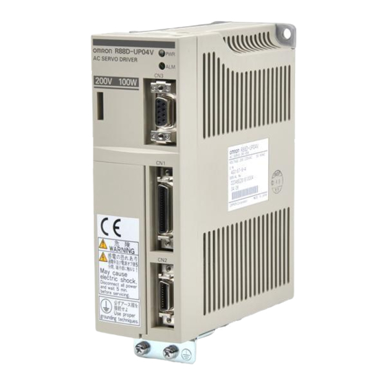
- Page 20 Introduction Chapter 1 Servo Driver Nomenclature H Front View CN4: Connector for monitor output Power supply indicator Alarm indicator CN3: Parameter Unit connector CN1: Control I/O connector Terminal block CN2: Encoder connector Artisan Technology Group - Quality Instrumentation ... Guaranteed | (888) 88-SOURCE | www.artisantg.com...
- Page 21 Introduction Chapter 1 Applicable Standards and Models 1-4-1 UL/cUL Standards H Applicable Standards Standard Product Applicable Standard File No. Remarks AC Servo Driver UL508C E179149 Power conversion equipment AC Servomotor UL1004 E179189 Electric motors AC Servo Driver cUL C22.2 No. 14 E179149 Industrial control equipment AC Servomotor...
- Page 22 Introduction Chapter 1 H Applicable Models AC Servomotors Power supply pp y AC Servo Drivers With incremental encoder 200 VAC R88D-UPjjV R88M-Ujjj30VA-j (See note.) 100 VAC R88D-UPjjW R88M-Ujjj30WA-j (See note.) Note Optional specifications (shaft profile: straight shaft with keys) Straight shaft with keys and without brake BS1: Straight shaft with keys and with brake Artisan Technology Group - Quality Instrumentation ...
- Page 23 Chapter 2 System Design and Installation Installation Wiring Products Conforming to UL/cUL and Wiring Products Not Conforming to Any Standards Wiring Products Conforming to EC Directives Artisan Technology Group - Quality Instrumentation ... Guaranteed | (888) 88-SOURCE | www.artisantg.com...
- Page 24 System Design and Installation Chapter 2 Installation and Wiring Precautions Caution Do not step on or place a heavy object on the product. Doing so may result in injury. Caution Do not cover the inlet or outlet ports and prevent any foreign objects from entering the product.
- Page 25 System Design and Installation Chapter 2 Installation 2-1-1 External Dimensions (Unit: mm) H AC Servo Drivers Conforming to UL/cUL Standards and AC Servomotors Not Conforming to Any Standards D R88D-UP02H(A)/UP03H(A)/UP04H(A)/UP08H(A) (200 VAC, 30 to 200 W) R88D-UP03L(A)/UP04L(A)/UP10L(A) (100 VAC, 30 to 100 W) Installation dimensions Three, M4 Two,...
- Page 26 System Design and Installation Chapter 2 H AC Servo Drivers Conforming to UL/cUL Standards and AC Servomotors Not Conforming to Any Standards (Contd.) D R88D-UP20H(A) (200 VAC, 750 W) and R88D-UP15LA (100 VAC, 300 W) Two, 6 dia. Two, R3 (165) Installation Four, M4...
- Page 27 System Design and Installation Chapter 2 H AC Servo Drivers Conforming to EC Directives D R88D-UP02V/UP03V/UP04V/UP08V (200 VAC, 30 to 200 W) R88D-UP03W/UP04W/UP10W (100 VAC, 30 to 100 W) Installation dimensions Two, 6 dia. Three, M4 D R88D-UP12V (200 VAC, 400 W) R88D-UP12W (100 VAC, 200 W) Installation dimensions...
- Page 28 System Design and Installation Chapter 2 H AC Servo Drivers Conforming to EC Directives (Contd.) D R88D-UP20V (200 VAC, 750 W) R88D-UP15W (100 VAC, 300 W) Two, 6 dia. Two, R3 Installation dimensions Four, M4 Artisan Technology Group - Quality Instrumentation ... Guaranteed | (888) 88-SOURCE | www.artisantg.com...
- Page 29 System Design and Installation Chapter 2 H Regeneration Unit D R88A-RG08UA (15) Dia.: 6 Installation dimensions Two, M4 160 130 149 (18.5) H Parameter Units D R88A-PR02U 18.5 Two, 4.5 dia. 1000 Artisan Technology Group - Quality Instrumentation ... Guaranteed | (888) 88-SOURCE | www.artisantg.com...
- Page 30 System Design and Installation Chapter 2 D R88A-PR03U 57.5 Artisan Technology Group - Quality Instrumentation ... Guaranteed | (888) 88-SOURCE | www.artisantg.com...
- Page 31 System Design and Installation Chapter 2 H AC Servomotors Conforming to UL/cUL Standards and AC Servomotors Not Conforming to Any Standards D 30-W/50-W/100-W Standard Models: R88M-U03030HA, R88M-U05030HA, R88M-U10030HA R88M-U03030LA, R88M-U05030LA, R88M-U10030LA 300±30 Encoder adapter Motor plug 14 dia. 300±30 Four, R3.7 Two, 4.3 dia.
- Page 32 System Design and Installation Chapter 2 H AC Servomotors Conforming to UL/cUL Standards and AC Servomotors Not Conforming to Any Standards (Contd.) D 200-W/300-W/400-W Standard Models: R88M-U20030HA, R88M-U40030HA R88M-U20030LA, R88M-U30030LA 300±30 Encoder adapter Motor plug 14 dia. 300±30 Four, 5.5 dia. Four, R5.3 70 dia.
- Page 33 System Design and Installation Chapter 2 H AC Servomotors Conforming to UL/cUL Standards and AC Servomotors Not Conforming to Any Standards (Contd.) D 750-W Standard Models: R88M-U75030HA 300±30 Encoder adapter Motor plug 14 dia. 300±30 Four, R8.2 Four, 7 dia. D 750-W Models with Brake: R88M-U75030HA-B 300±30 Encoder adapter...
- Page 34 System Design and Installation Chapter 2 H AC Servomotors Conforming to EC Directives D 30-W/50-W/100-W Standard Models: R88M-U03030VA-S1, R88M-U05030VA-S1, R88M-U10030VA-S1 R88M-U03030WA-S1, R88M-U05030WA-S1, R88M-U10030WA-S1 14 dia. Four, R3.7 Sh6 dia. Two, 4.3 dia. 46 dia. 30h7 dia. D 30-W/50-W/100-W Models with Brake: R88M-U03030VA-BS1, R88M-U05030VA-BS1, R88M-U10030VA-BS1 R88M-U03030WA-BS1, R88M-U05030WA-BS1, R88M-U10030WA-BS1 14 dia.
- Page 35 System Design and Installation Chapter 2 H AC Servomotors Conforming to EC Directives (Contd.) D 200-W/300-W/400-W Standard Models: R88M-U20030VA-S1, R88M-U40030VA-S1 R88M-U20030WA-S1, R88M-U30030WA-S1 14 dia. Four, 14h6 dia. 5.5 dia. Four, R5.3 70 dia. 50h7 dia. D 200-W/300-W/400-W Models with Brake: R88M-U20030VA-BS1, R88M-U40030VA-BS1, R88M-U20030WA-BS1, R88M-U30030WA-BS1 14 dia.
- Page 36 System Design and Installation Chapter 2 H AC Servomotors Conforming to EC Directives (Contd.) D 750-W Standard Models: R88M-U75030VA-S1 14 dia. Four, R8.2 Four, 7 dia. 90 dia. 16h6 dia. 70h7 dia. D 750-W Models with Brake: R88M-U75030VA-BS1 14 dia. Four, R8.2 Four, 7 dia.
- Page 37 System Design and Installation Chapter 2 H Shaft Dimensions of Motors With Keys Standard U-series AC Servomotors do not have keys on the shafts. The dimensions of motors with keys (produced on order) are shown below. Motors with keys are indicated by adding “-S1” to the end of the model number.
- Page 38 System Design and Installation Chapter 2 2-1-2 Installation Conditions H AC Servo Drivers D Space Around Drivers • Install Servo Drivers according to the dimensions shown in the following illustration to ensure proper heat dispersion and convection inside the panel. Also install a fan for circulation if Servo Drivers are installed side by side to prevent uneven temperatures from developing inside the panel.
- Page 39 System Design and Installation Chapter 2 D Keeping Foreign Objects Out of Units • Place a cover over the Units or take other preventative measures to prevent foreign objects, such as drill filings, from getting into the Units during installation. Be sure to remove the cover after installa- tion is complete.
- Page 40 System Design and Installation Chapter 2 • Bevel gears will cause a load to be applied in the thrust direction depending on the structural preci- sion, the gear precision, and temperature changes. Bevel gear Provide appropriate backlash or take other mea- sures to ensure that no thrust load is applied which exceeds specifications.
- Page 41 System Design and Installation Chapter 2 D Other Precautions • Do not apply commercial power directly to the Servomotor. The Servomotors run on synchronous AC and use permanent magnets. Applying 3-phase power will burn out the motor coils. • Do not carry or otherwise handle the Servomotor by its cable, otherwise the cable may become dis- connected or the cable clamp may become damaged.
- Page 42 Products Not Conforming to Any Standards 2-2-1 Connecting OMRON Servo Controllers Use general-purpose control cables (purchased separately) or Servo Relay Units for the C200H to connect U-series AC Servomotors and Servo Drivers to OMRON Servo Con- trollers. H Connecting SYSMAC C-series Position Control Units...
- Page 43 System Design and Installation Chapter 2 H Connecting SYSMAC C200H and C500Position Control Units (Using Servo Relay Units) C200H Position C200H Position Control Unit (1 axis) Control Unit (2 axes) C200H-NC112 C200H-NC211 C500 Position Control Unit C500-NC113 (1 axis) C500-NC211 (2 axes) Position Control Unit Connecting Position Control Unit Connecting Cable (for C200H-NC112)
- Page 44 System Design and Installation Chapter 2 H Connecting SYSMAC C200HX/HG/HE Position Control Units (Using Servo Relay Units) SYSMAC C200HX/HG/HE SYSMAC C200HX/HG/HE Position Control Unit Position Control Units C200HW-NC213 (2 axes) C200HW-NC113 (1 axis) C200HW-NC413 (4 axes) Position Control Unit Connecting Position Control Unit Connecting Cable (for C200HW-NC113) Cable (for C200HW-NC213/413)
- Page 45 System Design and Installation Chapter 2 2-2-2 Connector-Terminal Conversion Unit The AC Servo Driver can be easily connected to the Connector-Terminal Conversion Unit through a special cable without soldering. Controller XW2B-40F5-P Connector-Terminal Conversion Unit R88A-CTUjjjN Connector Cable for Connector-Terminal Conversion Unit OMNUC U-series AC Servo Driver Power Cable...
- Page 46 System Design and Installation Chapter 2 2-2-3 Wiring Servo Drivers Provide proper wire diameters, ground systems, and noise resistance when wiring terminal blocks. H Wiring Terminal Blocks Power supply input terminals Main-circuit DC output terminals To Motor White Blue Green Power Cable R88A-CAUjjjS R88A-CAUjjjB (with brake)
- Page 47 AWG 20 AWG 20 (see note) to AWG 18 terminal wire size Use OMRON standard cable. The applicable wire size for motor connectors is AWG22 to AWG18. Ground terminal Use 2.0-mm external ground wires. Use the same wire as used for the motor output.
- Page 48 System Design and Installation Chapter 2 2-2-4 Wiring for Noise Resistance H Wiring Method Noise resistance will vary greatly depending on the wiring method used. Resistance to noise can be increased by paying attention to the items described below. Servo Driver Servomotor R88D- R88M-...
- Page 49 System Design and Installation Chapter 2 • Use twisted-pair cables for the power supply cables whenever possible, or bind the cables. Driver Driver Binding • Separate power supply cables and signal cables when wiring. H Selecting Components This section describes the standards used to select components required to increase noise resistance. Select these components based on their capacities, performances, and applicable ranges.
- Page 50 System Design and Installation Chapter 2 Note 2. Refer to manufacturers documentation for operating details. 3. The surge immunity is for a standard impulse current of 8/20 µs. If pulses are wide, either decrease the Note current or change to a larger-capacity surge absorber. Note 4.
- Page 51 The Servo Driver inrush current is 50 A, and the momentary maximum current is approxi- mately twice the rated current. The following table shows the recommended contactors. Maker Model Rated current Momentary maxi- Coil voltage mum current OMRON G6C-2BND 10 A 24 VDC LY2-D 10 A 24 VDC G7L-2A-BUBJ...
- Page 52 System Design and Installation Chapter 2 Driver Leakage current (direct) Leakage current (resistor-capaci- (including high-frequency cur- tor, in commercial power supply rent) frequency range) R88D-UP02H(A) to -UP08H(A) 80 mA 3 mA R88D-UP12H(A) 60 mA 4 mA R88D-UP20H(A) 110 mA 5 mA Note 1.
- Page 53 System Design and Installation Chapter 2 • If the control power supply wiring is long, noise resistance can be improved by adding 1-µF laminated ceramic capacitors between the control power supply and ground at the Servo Driver input section and the controller output section. •...
- Page 54 System Design and Installation Chapter 2 2-2-5 Peripheral Device Connection Examples H Connecting to Peripheral Devices Single-phase, 200/230 VAC, 50/60 Hz (R88D-UPjjjH (A)) Single-phase, 100/115 VAC, 50/60 Hz (R88D-UPjjjL(A)) MCCB Noise filter Main-circuit Main-circuit connector power supply Class-3 ground (to 100 Ω or less) Surge killer Servo error display R88D-CAUjjjS...
- Page 55 System Design and Installation Chapter 2 H Connecting a Regeneration Unit Single-phase, 200/230 VAC, 50/60 Hz (R88D-UPjjH(A)) Single-phase, 100/115 VAC, 50/60 Hz (R88D-UPjjL(A)) OMNUC U-series Servo Driver 12 to 24 VDC ALMCOM External regeneration resistor Short bar R88A-RG08UA Regeneration Unit Note 1.
- Page 56 Chapter 2 Wiring Products Conforming to EC Directives 2-3-1 Connecting Servo Controllers Use general-purpose control cables (purchased separately) to connect U-series AC Servomotors and Servo Drivers to OMRON Servo Controllers. H Connecting to a Servo Controller Servo Controller General-purpose Control Cable...
- Page 57 System Design and Installation Chapter 2 2-3-2 Wiring Servo Drivers Provide proper wire diameters, ground systems, and noise resistance when wiring terminal blocks. H Wiring Terminal Blocks Power supply input terminals Main-circuit DC output terminals To Motor White Blue Power Cable R88A-CAU001 R88A-CAU01B (with brake) Green...
- Page 58 AWG 20 AWG 20 (see note) to AWG 18 terminal wire size Use OMRON standard cable. The applicable wire size for motor connectors is AWG22 to AWG18. Protective earth Use 2.0-mm external ground wires. Use the same wire as used for the motor output.
- Page 59 System Design and Installation Chapter 2 2-3-3 Wiring Products Conforming to EMC Directives Models conforming to EC Directive will meet the requirements of the EMC Directives EN55011 Class A Group 1 (EMI) and EN50082-2 (EMS) if they are wired under the conditions described in this section. If the connected devices, wiring, and other conditions cannot be made to fulfill the installation and wiring conditions when the product is incorporated into a machine, the compliance of the overall machine must be confirmed.
- Page 60 System Design and Installation Chapter 2 • No-fuse breakers (MCCB), surge absorbers, and noise filters (NF) should be positioned near the input terminal block (ground plate), and I/O lines should be isolated and wired using the shortest means possible. • Wire the noise filter as shown at the left in the following illustration. The noise filter should be installed at the entrance to the control panel whenever possible.
- Page 61 System Design and Installation Chapter 2 • Be sure that no gaps are created when installing the cover, as gaps can be caused by distortion when tightening screws. Case Case Cover Conductive Oil-proof Control panel packing packing Oil-proof packing Conductive packing Case (inside) H Selecting Components...
- Page 62 System Design and Installation Chapter 2 Maker Model Max. limit Surge Type Remarks voltage immunity Okaya Block R.A.V-781BYZ-2 783 V 1,000 A For power supply line Electric Ind. i I d R.A.V-781BXZ-4 783 V 1,000 A For power supply line ground Note 1.
- Page 63 The following table shows the recommended contactors. Maker Model Rated current Momentary maxi- Coil voltage mum current OMRON J7AN-E3 15 A 120 A 24 VDC D Leakage Breakers • Select leakage breakers designed for inverters.
- Page 64 System Design and Installation Chapter 2 Note 3. Leakage current for 100-VAC-input Servomotors is approximately half that of the values shown above. H Improving Encoder Cable Noise Resistance The following encoder signals are used: A, B, and S phase. The frequency for A- or B-phase signals is 154 kHz max.;...
- Page 65 System Design and Installation Chapter 2 2-3-4 Peripheral Device Connection Examples H Connecting to Peripheral Devices Single-phase, 200/230 VAC, 50/60 Hz (R88D-UPjjV) Single-phase, 100/115 VAC, 50/60 Hz (R88D-UPjjW) MCCB Noise filter Main-circuit Main-circuit connector power supply Class-3 ground (to 100 Ω or less) Surge killer Servo error display R88D-CAU001...
- Page 66 Chapter 3 Operation 3-1 Operational Procedure 3-2 Turning On Power and Checking Displays 3-3 Using Parameter Units 3-4 Initial Settings: Setup Parameters 3-5 Setting Functions: User Parameters 3-6 Trial Operation 3-7 Making Adjustments 3-8 Regenerative Energy Absorption Artisan Technology Group - Quality Instrumentation ... Guaranteed | (888) 88-SOURCE | www.artisantg.com...
- Page 67 Operation Chapter 3 Operation and Adjustment Precautions Caution Check the newly set parameters for proper execution before actually running them. Not doing so may result in equipment damage. Caution Do not make any extreme adjustments or setting changes. Doing so may result in unstable operation and injury.
- Page 68 Operation Chapter 3 Operational Procedure After confirming that the system has been correctly installed and wired, make the initial settings for the Servo Driver. Then, set the functions as required for the application of the Servomotor. Any incorrect settings in the parameters could cause unexpected motor operation, creating an extremely dangerous situation.
- Page 69 Operation Chapter 3 Turning On Power and Checking Displays 3-2-1 Items to Check Before Turning On Power H Checking Power Supply Voltage • Check to be sure that the power supply voltage is within the ranges shown below. R88D-UPjjH(A) (200 VAC specifications): Single-phase 200/230 VAC (170 to 253 V) 50/60 Hz R88D-UPjjL(A) (100 VAC specifications): Single-phase 100/115 VAC (85 to 127 V) 50/60 Hz R88D-UPjjV (200 VAC specifications): Single-phase 200/230 VAC (170 to 253 V) 50/60 Hz...
- Page 70 Operation Chapter 3 H Checking Displays • When the power is turned on, one of the codes shown below will be displayed. Normal (Base block) Error (Alarm Display) Note 1. “Base block” means that the Servomotor is not receiving power. Note 2.
- Page 71 Operation Chapter 3 Using Parameter Units The key operations for the Hand-held R88A-PR02U Parameter Unit and the Mounted R88A-PR03U Parameter Unit vary depending on the functions used. 3-3-1 Parameter Unit Keys and Functions Hand-held Mounted PR02U PR03U Function Parameter Unit Parameter Unit Alarm reset R88A-PR02U...
- Page 72 Operation Chapter 3 H Changing Modes To change modes, press the MODE/SET Key. Status display Alarm history Power ON Settings mode Monitor mode mode display mode (Display example) -. b b c n - 0 0 u n - 0 0 0 - a.0 2 3-3-3 Mode Changes and Display Contents The following diagram shows the functions and references for each mode.
- Page 73 Operation Chapter 3 Power ON Bit Displays (page 104) Power ON Base block (motor not receiving power) Status display Positioning completion mode Command pulse input -. b b (Display example) Motor rotation detected / Current limit detected Symbol Displays Base block r U n In operation (running) p % t...
- Page 74 Operation Chapter 3 Initial Settings: Setup Parameters Setup parameters are parameters that are essential for starting up the system. They in- clude I/O signal function changes, selection of processing for momentary stops and er- rors, command pulse modes, and so on. Set them to match the user system. Once the parameters have been set, they become effective when the power supply is turned on again after having been turned off.
- Page 75 Operation Chapter 3 3. Repeat steps 1 and 2 above as required. 4. Save the data in memory by pressing the DATA Key. 5. With this, the parameter setting operation is complete. Pressing the DATA Key at this point will bring back the parameter number display.
- Page 76 Operation Chapter 3 Item Bit no. Factory Setting Explanation setting Pulse stop switching Position Control (when bit 2 of Cn-02 is 0) (HA/LA/V/W Models) Disables the pulse stop input. (CN1-15 is the gain reduction (MING).) Internal speed control settings (when bit 2 of Cn-02 is 1) Command pulses aren’t received when PCL and NCL are OFF.
- Page 77 Operation Chapter 3 H Setup Parameter No. 2 (Cn-02) Item Factory Setting Explanation setting Reverse rotation mode Rotates in the CCW direction with a + command. (See note Rotates in the CW direction with a + command. Not used. Input command mode Position control with pulse-train input: CN1-11 and 12 are used as forward and reverse current limit inputs (PCL, NCL).
- Page 78 Operation Chapter 3 3-4-3 Important Setup Parameters (Cn-01 and Cn-02) This section explains the particularly important setup parameters. If these parameters aren’t set proper- ly, the motor might not operate or might operate unpredictably. Set these parameters appropriately for the system being used. H Control Mode Settings The control mode is determined by the following setup parameters: •...
- Page 79 Operation Chapter 3 H Error Stop Processes Bits 6, 7, 8, and 9 of Cn-01 specify how the motor will be stopped when the servo goes OFF (the run command is OFF), an alarm is generated, or overtravel occurs. The following diagrams show the func- tion of these four bits: Stop Process for Servo OFF/Alarm Bit 7...
- Page 80 Operation Chapter 3 3-5-1 Setting and Checking User Parameters (Cn-04 to 29) H Displaying User Parameters Perform the following procedures on the Parameter Unit to display the user parameters. D Displaying with Handy-type (R88A-PR02U) 1. Press the MODE/SET Key to go into settings mode (cn-jj). 2.
- Page 81 Operation Chapter 3 6. Repeat steps 1 through 5 above as required to set other parameters. Note 1. Settings can also be made by pressing only the Up and Down Keys in stead of using steps 1. and 2. This will enable setting digits higher than the one that is blinking. Use whichever meth- od is faster for the number of digits that need to be set.
- Page 82 Operation Chapter 3 Parameter name Factory Unit Setting Explanation setting range Cn-0b Rotational speed for motor r/min 1 to 4,500 Setting for rotational speed for rotation detection motor rotor detection output. Cn-0C P control switching (torque 0 to maxi- If a torque command exceeds commands) mum torque this value, the mode switches...
- Page 83 Operation Chapter 3 Parameter name Factory Unit Setting Explanation setting range Cn-23 Software start deceleration 0 to 10,000 Sets the deceleration time for time software starts. Cn-24 Electronic gear ratio G1 1 to 65,535 Setting range 1/100 ≤ G1/G2 ≤ 100 (numerator) (see note 2) / 00 G /G...
- Page 84 Operation Chapter 3 3-5-3 Internal Speed Control Settings H Function • This function controls Servomotor speed using the speeds set in the parameters (No. 1, No. 2, and No. 3 internal speed settings). • The internal speed is selected with control input terminals CN1-11 and CN1-12 (speed selection commands 1 and 2).
- Page 85 Operation Chapter 3 H User Parameter Settings Parameter name Factory Unit Setting Explanation setting range Cn-07 Software start acceleration 0 to 10,000 Sets the time for the motor to time accelerate from 0 r/min to 4,500 r/min. Cn-23 Software start deceleration 0 to 10,000 Sets the time for the motor to time decelerate from 4,500 r/min to...
- Page 86 Operation Chapter 3 H Operation Example D Internal Speed Control Settings + Position Control (HA/LA/V/W Models) Speed selection command 1 SPD1 6 ms min. Speed selection command 2 SPD2 Switch rotation direction RDIR 6 ms min. Pulse command Positioning completed (INP) Speed 3 Speed 2...
- Page 87 Operation Chapter 3 Parameter name Factory Unit Setting Explanation setting range Setting range Cn-24 Electronic gear ratio G1 1 to 65,535 1/100 ≤ G1/G2 ≤ 100 / 00 G /G (numerator) Cn-25 Electronic gear ratio G2 1 to 65,535 (denominator) Note The factory settings will produce turn the motor once for every 2,048 input pulses.
- Page 88 Operation Chapter 3 H Operation • Incremental pulses are output from the Servo Driver through a frequency divider. Servo Driver Encoder A-phase Frequency divider B-phase Processing circuitry Z-phase • The output phases of the encoder signal output from the Servo Driver are as shown below (when divider rate Cn-0A = 2,048).
- Page 89 Operation Chapter 3 3-5-6 Bias Function: Position Control The bias function shortens positioning time by adding the bias rotational speed to the speed command when the residual pulses in the deviation counter exceed the position- ing completion range. H Function •...
- Page 90 Operation Chapter 3 3-5-7 Torque Limit Function H Function • This function limits the Servomotor’s output torque. • This function can be used to protect the Servomotor and machine system by preventing excessive force or torque on the machine system when the machine (moving part) pushes against the work- piece with a steady force, such as in a bending machine.
- Page 91 Operation Chapter 3 3-5-8 Brake Interlock (For Motors with Brakes) H Magnetic Brakes The magnetic brakes for Servomotors with brakes are specialized holding brakes with non-magnetized operation. Therefore set the parameters so that the brake power supply is turned off after the Servomo- tor stops.
- Page 92 Operation Chapter 3 H Operation D Timing for Run Command (RUN) (When Servomotor is Stopped) Run instruction 25 to 35 ms Approx. 6 ms Brake interlock signal BKIR Brake power supply 200 max. 100 max. Cancelled Brake operation Maintained (See note 1) Pulse train command CW/CCW...
- Page 93 Operation Chapter 3 D Timing for Run Command (RUN), Errors, Power Supply: Servomotor Stopped Power supply Run command Alarm output (See note 2) Brake interlock signal BKIR Power on Power to motor Power off Approx. 10 ms (See note 1.) Motor rotational speed Brake command speed...
- Page 94 Operation Chapter 3 Trial Operation After the wiring is complete and the parameter settings have been made, conduct a trial operation. First, check with rotation of the motor without connecting a load (i.e., without connecting the mechanical system). Then, connect the mechanical system, auto-tune the system, and confirm that the correct operation pattern is performed.
- Page 95 Operation Chapter 3 7. Press the DATA Key again to return to the parameter number display. (2) Jog Operations (See 3-6-2 Jog Operations.) • Perform jog operations using the Parameter Unit and confirm the following: Does the motor turn in the correct direction? Is there any unusual sound or vibration? Do any error occur? •...
- Page 96 Operation Chapter 3 3-6-2 Jog Operations Jog operations rotate the Servomotor in a forward or reverse direction using the Parameter Unit. Jog operations are made possible when system check mode Cn-00 is set to “00.” The items in parentheses in the following explanation indicate operations using the Handy-type Parameter Unit. DATA Indicates settings mode.
- Page 97 Operation Chapter 3 Making Adjustments 3-7-1 Auto-tuning Auto-tuning rotates the Servomotor with a load connected (mechanical system), and au- tomatically adjusts the position loop gain, the speed loop gain, and the speed loop in- tegration time constant. When adjustments cannot be made by auto-tuning, refer to 3-7-2 Manually Adjusting Gain.
- Page 98 Operation Chapter 3 9. Press the SERVO (DATA) Key to turn on the servo. (This step is not required if the Run Command Input is ON.) 10. Perform auto-tuning, using the Up Key for forward operation and the Down Key for reverse opera- tion.
- Page 99 Operation Chapter 3 • If auto-tuning does not complete or if the gain set via auto-tuning is not sufficient, adjust the gain manu- ally using the procedure in 3-7-2 Manually Adjusting Gain. 1/2 jog speed Approx. 1.1 s Approx. 0.7 s Artisan Technology Group - Quality Instrumentation ...
- Page 100 Operation Chapter 3 3-7-2 Manually Adjusting Gain Make sure that Cn-28 for compensation gain adjustment is set to 0 before performing auto-tuning. This parameter is factory-set to 0. Caution Never make extreme changes in the setting. Doing so may cause unstable operation or result in injury.
- Page 101 Operation Chapter 3 D Gain Adjustment Standards The following table shows reference values for gain adjustment. Adjustments can be made quickly if these values are used as standards. Make the initial gain setting based on the load inertia. Load inertia Speed loop gain Speed loop Position loop gain...
- Page 102 Operation Chapter 3 D Adjusting the Speed Loop Integration Time Constant Parameter name Factory Unit Setting Explanation setting range Cn-05 Speed loop integra- 1 ms/ 2 to Speed loop integration constant. tion constant 0.01 ms 10,000 As the constant is increased, the response is shortened and the resiliency toward ex- ternal force is weakened.
- Page 103 Operation Chapter 3 D Position Loop Gain The responsiveness of the servo system is determined by the position loop gain. When a servo system has high position loop gain, the responsiveness is greater and positioning can be faster. In order for position loop gain to be raised, the mechanical rigidity and the characteristic frequency must be in- creased.
- Page 104 Operation Chapter 3 Increasing the feed-forward amount to much will cause excessive overshooting. The feed-forward amount is not sent through the deviation counter, but is applied directly to the speed loop. The differential of the deviation counter is thus not applied, causing a faster response when the load response is delayed from the commands.
- Page 105 Operation Chapter 3 Set the compensating gain to 0 when auto-tuning. The gain will not be adjusted correctly if the compen- sating gain is not set to 0. D Position Loop Block Diagram Cn-1d Cn-24,25 Cn-27 Cn-1C Electronic Feed-forward Feed-forward Bias rotational gear ratio amount...
- Page 106 Operation Chapter 3 H Horizontal Axle Motor operation Motor output torque Note In the output torque graph, when the rotation direction and the torque direction match it is shown as positive. The regenerative energy for each section can be found by means of the following formulas: = 1/2 S N S 0.105 [J] = 1/2 S N...
- Page 107 Operation Chapter 3 H Vertical Axle Rising Motor operation Falling Motor output torque Note In the output torque graph, when the rotation direction and the torque direction match it is shown as positive. The regenerative energy for each section can be found by means of the following formulas: = 1/2 S N S 0.105 [J] S 0.105 [J]...
- Page 108 Operation Chapter 3 Connect an external regeneration resistor when the regeneration processing power of the Regenera- tion Unit (12 W) is exceeded. Refer to 3-8-3 Absorption of Regenerative Energy with the External Re- generation Resistor for details on external regeneration resistors. 3-8-2 Servo Driver Absorbable Regenerative Energy H Regenerative Energy Absorbed Internally The Servo Driver absorbs regenerative energy by means of an internal capacitor.
- Page 109 Operation Chapter 3 D 100-VAC Input Type Model Absorptive regen- Maximum applicable Remarks (see note *3) eration energy (J) load inertia –4 (x10 kgSm Rotor inertia × 30, 4,500 r/min R88D-UP03L(A)/UP03W 0.63 (30 W) Rotor inertia × 30, 4,500 r/min R88D-UP04L(A)/UP04W 0.78 (50 W)
- Page 110 Operation Chapter 3 D R88D-UP08H(A)/-UP08V (200 W) R88D-UP12L(A)/-UP12W (200 W) Applicable load inertia –4 (×10 kgSm 200W 3.69 × 10 –4 kgSm 2.15 Rotation speed (r/min) D R88D-UP12H(A)/-UP12V (400 W) R88D-UP15LA/-UP15W (300 W) Applicable load inertia –4 (×10 kgSm 300W, 400W 3.8 × 10 –4 kgSm UA15LA...
- Page 111 Operation Chapter 3 D R88D-UP20H(A)/-UP20V (750 W) Applicable load inertia –4 (×10 kgSm 700W 13.4 × 10 –4 kgSm Rotation speed (r/min) 3-8-3 Absorption of Regenerative Energy with the External Regeneration Resistor (Models Conforming to UL/cUL Standards and Models Not Conforming to Any Standards) Connect one or more external regeneration resistors when a Regeneration Unit (R88A- RG08UA) cannot absorb all of the regenerative energy.
- Page 112 Operation Chapter 3 D Combining External Regeneration Resistors Regeneration absorption capacity Item 70 W 280 W Combining external regeneration resistors Note Use a combination with an absorption capacity larger than the average regenerative power (P D Dimensions (Unit: mm) Thermal switch output 1.5 dia.
- Page 113 Operation Chapter 3 3-8-4 Processing Regenerative Energy with Multiple Axes (Models Conforming to EC Directives) When using multiple axes, the + terminals on the Servo Drivers can be connected to- gether and the – terminals can be connected together to use regenerative energy as the drive energy for the other axes, thus absorbing the energy.
- Page 114 Chapter 4 Application Using Displays Using the Monitor Output Protective and Diagnostic Functions Troubleshooting Periodic Maintenance Artisan Technology Group - Quality Instrumentation ... Guaranteed | (888) 88-SOURCE | www.artisantg.com...
- Page 115 Using Displays 4-1-1 Display Functions OMRON U-series AC Servomotors have unique servo software that enables quantita- tive monitoring in real time, on digital displays, of changes in a variety of characteristics. Use these displays for checking the various characteristics during operation.
- Page 116 Application Chapter 4 H Parameter Unit Key Functions The contents displayed by the Parameter Unit can be changed by key operations. Handy-type Mounted Function Parameter Unit Parameter Unit R88A-PR02U R88A-PR03U Alarm reset RESET Mode switching; data memory Servo ON/OFF during jog operations SERVO DATA Switching between parameter display and data display;...
- Page 117 Application Chapter 4 H Changing the Mode Use the MODE/SET Key to change from one mode to another. Status display Alarm history Power ON Settings mode Monitor mode mode display mode -. b b c n - 0 0 u n - 0 0 0 - a.0 2 (Display example) 4-1-2 Status Display Mode...
- Page 118 Application Chapter 4 H Symbol Display Contents Symbol display Contents Base block (no power to motor) Operating Forward rotation prohibited Reverse rotation prohibited a.jj Alarm display (Refer to alarm table.) 4-1-3 Monitor Mode (Un-) H Types of Monitoring In monitor mode, ten types of monitoring can be carried out. Monitor no.
- Page 119 Application Chapter 4 1. Press the MODE/SET Key to go into monitor mode. 2. Using the Up and Down (and Right and Left) Keys, set the monitor number. 3. Press the DATA Key to display the monitor data. 4. Press the DATA Key to return to the monitor number display. 5.
- Page 120 Application Chapter 4 Monitor Bit no. Symbol Contents Un-05 Lit when alarm is generated. DBON Lit during dynamic brake operation. Lit when in reverse rotation mode (when Cn-02 bit no. 0 = 1). TGON/ Lit when the motor rotational speed is equal to or greater than the CLIMT rotational speed for motor rotation detection (Cn-0b).
- Page 121 Application Chapter 4 H Servomotor Parameter Checking Operation The items in parentheses in the following explanation indicate operations using the Handy-type Param- eter Unit. DATA Indicates settings mode. System check mode Data 1. Press the MODE/SET Key to switch to the settings mode. 2.
- Page 122 Application Chapter 4 Using the Monitor Output The Servo Drive outputs a monitor voltage proportional to the Servomotor rotation speed and current from the monitor output connector (CN4) on the top of the Servo Driv- er. This output can be used to install a meter in the control panel or to enable more pre- cise gain adjustments.
- Page 123 Application Chapter 4 H Analog Monitor Cable (R88A-CMW001S) Use this cable to connect the Servo Driver’s Analog Monitor Connector. Servo Driver External devices R88D-jj 1.7 dia. Servo Driver Symbol Connector socket model White DF11-4DS-2C (Hirose) Black Connector socket model Black DF11-2428SCF (Hirose) Cable: AWG24 x 4C UL1007 Artisan Technology Group - Quality Instrumentation ...
- Page 124 Application Chapter 4 Protective and Diagnostic Functions 4-3-1 Alarm Displays and Alarm Code Outputs The Servo Driver has the error detection functions shown below. When an error is de- tected, the alarm output (ALM ) and the alarm code output (AL01-03) are output, the Ser- vo Driver’s internal power drive circuit is turned off, and the alarm is displayed.
- Page 125 Application Chapter 4 4-3-2 Alarm Output This section describes the timing of alarm outputs when power is turned on and when alarms occur. The method used to clear alarms is also described. H Timing Chart Power input (R, T) Run command (RUN) Error Error...
- Page 126 Application Chapter 4 4-3-3 Overload Characteristics (Electron Thermal Characteristics) An overload protection function (electron thermal) is built into the Servo Driver to protect against Servo Driver or Servomotor overload. If an overload (A.70 to A.72) does occur, first clear the cause of the error and then wait at least one minute for the Servomotor temperature to drop before turning on the power again.
- Page 127 Application Chapter 4 4-3-4 Alarm History Display Mode The Servo Driver stores the history of the 10 most recent alarms that have been gener- ated. The alarm history can be displayed by going into the alarm history display mode and using the Up and Down Keys. To clear the alarm history, set the system check mode to “02”...
- Page 128 Application Chapter 4 Troubleshooting When an error occurs, check the error contents by means of the operating status and alarm display, investigate the cause and apply the appropriate countermeasures. H Error Diagnosis by Means of Operating Status Symptom Probable cause Items to check Countermeasures •...
- Page 129 Application Chapter 4 Symptom Probable cause Items to check Countermeasures Servomotor operation is The Servomotor power lines Check the Servomotor pow- Correct the wiring. unstable. or encoder lines are wired er line U, V, and W phases, incorrectly. and the encoder line wiring. The settings for the bias Adjust bias revolutions and function are not correct.
- Page 130 Application Chapter 4 H Error Diagnosis by Means of Alarm Display (Parameter Unit) Alarm Error content Condition when error oc- Probable cause Countermeasures display curred Parameter cor- Occurred when power was Internal memory error Replace Servo Driver. a.02 ruption turned on. a.04 Parameter set- Occurred when power was...
- Page 131 Application Chapter 4 Alarm Error content Condition when error oc- Probable cause Countermeasures display curred Deviation count- Occurred when Servomotor a.31 Servomotor power lines or Correct the wiring. er overflow did not operate even when encoder lines are wired in- command pulse train was correctly.
- Page 132 Application Chapter 4 Alarm Error content Condition when error oc- Probable cause Countermeasures display curred • If the Servomotor shaft is Overload Occurred during operation. Operating at more than 120% of the rated torque. locked, unlock it. (A.70) HA/LA/V/W Models •...
- Page 133 Application Chapter 4 Alarm Error content Condition when error oc- Probable cause Countermeasures display curred • Connector contact faulty. • Insert connectors correct- Parameter Unit Occurred when power was cpf00 transmission er- ss o e turned on. u ed o ror 1 •...
- Page 134 Contact your OMRON representative for inspection and the necessity of any component replacement. Artisan Technology Group - Quality Instrumentation ... Guaranteed | (888) 88-SOURCE | www.artisantg.com...
- Page 135 Chapter 5 Specifications Servo Driver Specifications Servomotor Specifications Cable Specifications Parameter Unit Specifications Regeneration Unit Specifications Front-surface Mounting Bracket Specifications Artisan Technology Group - Quality Instrumentation ... Guaranteed | (888) 88-SOURCE | www.artisantg.com...
- Page 136 Specifications Chapter 5 Servo Driver Specifications 5-1-1 General Specifications Item Specifications Operating ambient temperature 0°C to 55°C Operating ambient humidity 35% to 85% RH (with no condensation) Storage ambient temperature –10°C to 75°C Storage ambient humidity 35% to 85% RH (with no condensation) Storage and operating atmo- No corrosive gasses.
- Page 137 Specifications Chapter 5 5-1-2 Performance Specifications H 200-VAC Input Servo Drivers Conforming to UL/cUL Standards and 200-VAC Input Servo Drivers Not Conforming to Any Standards Item R88D- R88D R88D R88D R88D R88D UP02H(A) -UP03H(A) -UP04H(A) -UP08H(A) -UP12H(A) -UP20H(A) Continuous output current (0-P) 0.6 A 0.85 A 1.2 A...
- Page 138 Specifications Chapter 5 H 100-VAC Input Servo Drivers Conforming to UL/cUL and 100-VAC Input Servo Drivers Not Conforming to Any Standards Item R88D- R88D- R88D- R88D- R88D- UP03L(A) UP04L(A) UP10L(A) UP12L(A) UP15LA Continuous output current (0-P) 0.9 A 1.3 A 3.1 A 3.8 A 4.8 A...
- Page 139 Specifications Chapter 5 Item R88D- R88D- R88D- R88D- R88D- UP03L(A) UP04L(A) UP10L(A) UP12L(A) UP15LA External regeneration processing Required for regeneration of more than 30 times the motor’s ro- Required for tor inertia. regeneration of more than 20 times the motor’s rotor inertia.
- Page 140 Specifications Chapter 5 Item R88D- R88D R88D R88D R88D R88D UP02V -UP03V -UP04V -UP08V -UP12V -UP20V Output Position feedback output A-, B-, Z-phase line driver output (EIA RS-422A) signals A-phase and B-phase (dividing rate setting): 16 to 2,048 pulses/revolution Z-phase: 1 pulse/revolution Speed monitor output 0.5 V/1,000 r/min Current monitor output...
- Page 141 Specifications Chapter 5 Item R88D-UP03W R88D-UP04W R88D-UP10W R88D-UP12W R88D-UP15W Output Position feedback output A-, B-, Z-phase line driver output (EIA RS-422A) A-phase and B-phase (dividing rate setting): 16 to 2,048 pulses/revolution signals Z-phase: 1 pulse/revolution Speed monitor output 0.5 V/1,000 r/min Current monitor output 0.5 V/100% Sequence output...
- Page 142 Specifications Chapter 5 H Terminal Block Specifications, Models Conforming to EC Directives Signal Function Condition Power supply in- R88D-UPjjV (200-VAC Units): Single-phase 200/230 VAC (170 to 253 VAC) 50/60 Hz R88D-UPjjW (100-VAC Units): Single-phase 100/115 VAC (85 to 127 VAC) 50/60 Hz Main circuit DC When using multiple axes and there is excessive regenerative energy, the + –...
- Page 143 Specifications Chapter 5 H CN1: Control I/O Specifications (Common to Models Conforming to UL/cUL Standards, Models Not Conforming to Any Standards, and Models Conforming to EC Directives) D CN1: Control Input Pin No. Signal name Function Contents Feed pulse, reverse pulse, Line driver input: 6 mA at 3V +PULS/CW/A 90_ differential phase...
- Page 144 Specifications Chapter 5 D CN1: Control Output Pin No. Signal name Function Contents BKIR Brake interlock output Outputs external brake interlock signal. Positioning competed out- Turned ON when the pulse count remaining in the deviation counter is equal to or less than the posi- tioning completed range set in user parameter Cn-1b.
- Page 145 Specifications Chapter 5 D Pin Arrangement Encoder +feed pulse, signal +PULS 19 EGND reverse pulse, output /CW/A –feed pulse, Encoder A phase –PULS reverse pulse, 20 +A A-phase +direction /CW/A Encoder A phase + output +SIGN/ signal, for- A-phase 21 –A CCW/B ward pulse, –direction...
- Page 146 Specifications Chapter 5 H Control Input Interface The input circuit for the control I/O connector (CN1) is as shown in the following diagram. 4.7 k 3.3 k +24 VIN External power supply 24-VDC ± 1 V 50 mA min. 5 mA To other input circuit GNDs To other input circuits D Run Command (14: RUN)
- Page 147 Specifications Chapter 5 cording to the settings of bits nos. 6, 8, and 9 of setup parameter no. 1 (Cn-01). Alarm status will not be generated at the Driver. When drive prohibition is not used, clear the function by connecting the respec- tive signal to the external power supply +24-V GND or setting setup parameter Cn-01, bit nos.
- Page 148 Specifications Chapter 5 Open-collector Input When connected with open collector output, insert a current limit resistor as shown below. Controller side Servo Driver side 220 Ω – – When Vcc = 5 V: R = 0 Ω When Vcc = 12 V:R = 750 Ω When Vcc = 24 V:R = 1.6 kΩ...
- Page 149 Specifications Chapter 5 Bits Logic Input Command Input pins Forward motor Reverse motor factor factor p lse pulse commands commands commands commands mode Positive Forward 1: +PULS pulse and 2: –PULS direction 3: +SIGN “L” “H” signal 4: –SIGN Reverse 1: +CW “L”...
- Page 150 Specifications Chapter 5 w Command Pulse Timing Command pulse Timing mode Forward pulse Forward commands Reverse commands and direction Direction signal τ Maximum frequency: 200 kpps Pulse τ ≥ 2.5µs t1≤ 0.1µs t2> 3.0µs T≥ 5.0µs Reverse pulse Forward commands and forward pulse Reverse commands Maximum...
- Page 151 Specifications Chapter 5 D Control Output Sequence Power supply input (R, T) Approx. 2 s Alarm output (ALM) 6 ms Positioning completed output (INP) Brake interlock output (BKIR) 25 to 35 ms 6 ms Run command input (RUN) Alarm reset input (RESET) Alarm code outputs (ALO1, ALO2, ALO3)
- Page 152 Specifications Chapter 5 • Current Limit Detection (9: CLIMIT; Setup Parameter Cn-01 Bit No. 4 = 1) When the forward current limit (PCL) and the reverse current limit (NCL) are input, this signal is out- put when the Servomotor’s output torque reaches the lower of the two following torque limit values: the torque limit value set for user parameters Cn-18, -19 (forward/reverse rotation external current limit) or the torque limit value set for user parameters Cn-08, -09 (forward/reverse rotation torque limit).
- Page 153 Specifications Chapter 5 • Output Circuit and Receiving Circuit Servo Driver Controller on User’s Side CN1- +5 V A-phase A-phase –A –A B-phase B-phase –B –B Z-phase Z-phase –Z –Z Output line driver SN75ALS 174NS or equivalent EGND Applicable line receiver TI-SN75175/MC3486/AM26LS32 R = 220 to 470 Ω...
- Page 154 Specifications Chapter 5 H Control I/O Signal Connections and External Signal Processing 220 Ω Reverse pulse BKIR Brake interlock –CW Forward pulse 220 Ω +CCW Positioning completion Maximum operating –CCW voltage: 30 VDC TGON Maximum output Deviation counter reset Motor rotation current: 50 mA...
- Page 155 Specifications Chapter 5 H CN2: Encoder Input Specifications Pin No. Signal name Function Interface 1, 2, 3 Encoder power supply GND Power supply outlet for encoder: 5 V, 120 mA 4, 5, 6 Encoder power supply +5 V Rotation direction switch input Connects to E0V when reverse rotation is executed by + input.
- Page 156 Specifications Chapter 5 When the rotation direction is changed, the encoder A-phase and B-phase output phases are also changed. When not set, + voltage is for forward rotation and A-phase advance; when set, + voltage if for reverse rotation and A-phase advance (and - voltage is for forward rotation and B-phase advance). Therefore wiring changes are unnecessary for encoder signals to the position controller.
- Page 157 Dai-ichi Denshi Kogyo Socket at Servo Driver 17LE-13090-27 (D2BC) Soldered plug at cable side 17JE-23090-02 (D1) Cover at cable side 17JE-09H-15 OMRON Soldered plug at cable side XM2A-0901 Cover at cable side XM2S-0912 H CN4: Speed/Current Monitor Specifications Signal Function...
- Page 158 Specifications Chapter 5 D Forward Torque Control: Cn-08 Reverse Torque Control: Cn-09 The Servomotor output torque control value for forward rotation is set in Cn-08, and the value for re- verse rotation is set in Cn-09. The setting range is 0 to the maximum torque, and the factory setting is for the maximum torque.
- Page 159 Specifications Chapter 5 If the run command turns off , a servo error occurs, or the main-circuit power supply turns off during operation of a Servomotor with a brake, the dynamic brake comes on (setup parameter Cn-01 bit no. 6 = 0) and Servomotor rotation speed is decreased.
- Page 160 Specifications Chapter 5 D Feed-forward Amount: Cn-1d This is the feed forward compensation for the position controller. Positioning time is shortened by ad- ding the command pulse differential to the speed command. The setting range is 0 to 100%, and the factory setting is 0%.
- Page 161 Specifications Chapter 5 Adjust the compensation gain after adjusting the speed loop gain with Cn-04 and the speed loop inte- gral time constant with Cn-05. The compensation gain may not be 100 due to the speed loop gain and speed loop integral time constant set with Cn-04 and Cn-05, in which case increasing the compensation gain will cause an error.
- Page 162 Specifications Chapter 5 Servomotor Specifications 5-2-1 General Specifications Item Specifications Operating ambient temperature 0°C to 40°C Operating ambient humidity 20% to 80% RH (with no condensation) Storage ambient temperature –10°C to 75°C Storage ambient humidity 20% to 85% RH (with no condensation) Storage and operating atmo- No corrosive gasses.
- Page 163 Specifications Chapter 5 5-2-2 Performance Specifications H 200 VAC Servomotors Item Unit R88M R88M R88M R88M R88M R88M -U03030H(A) -U05030H(A) -U10030H(A) -U20030H(A) -U40030H(A) -U75030H(A) -U03030VA -U05030VA -U10030VA -U20030VA -U40030VA -U75030VA Rated output (see note) Rated torque 0.095 0.159 0.318 0.637 1.27 2.39 (see note)
- Page 164 Specifications Chapter 5 D AC Servomotor Heat Radiation Conditions When an AC Servomotor is continuously operated at the rated conditions, a heat radiation plate equiva- lent to an rectangular aluminum plate of t6 × 250 mm is required at the Servomotor flange mounting area.
- Page 165 Specifications Chapter 5 H Specifications for Servomotors with Magnetic Brakes The magnetic brakes installed in Servomotors with brakes are status-holding brakes with non-magnetized operation. The magnetic brake is released when a magnetic cur- rent (24 VDC) is applied. The magnetic brake is not meant to be used for braking. Using it for braking will damage it.
- Page 166 Specifications Chapter 5 5-2-3 Torque and Rotational Speed Characteristics H Torque Characteristics (With 3-m Standard Cable and 200-VAC Input) R88M-U03030H(A) R88M-U05030H(A) R88M-U10030H(A) R88M-U03030VA R88M-U05030VA R88M-U10030VA Frequent use Frequent use Frequent use Continuous use Continuous use Continuous use R88M-U20030H(A) R88M-U40030H(A) R88M-U75030H(A) R88M-U20030VA R88M-U40030VA R88M-U75030...
- Page 167 Specifications Chapter 5 H Torque Characteristics (With 3-m Standard Cable and 100-VAC Input) R88M-U03030L(A) R88M-U05030L(A) R88M-U10030L(A) R88M-U03030WA R88M-U05030VA R88M-U10030VA Frequent use Frequent use Frequent use Continuous use Continuous use Continuous use R88M-U20030L(A) R88M-U30030LA R88M-U20030WA R88M-U30030WA Frequent use Frequent use Continuous use Continuous use H Servomotor and Mechanical System Temperature Characteristics •...
- Page 168 Specifications Chapter 5 5-2-4 Allowable Loads on Servomotor Shafts The allowable loads on Servomotor shafts are shown in the following table. Operate the Servomotor at no more than the allowable radial and thrust loads. At the time of assembly, assemble the Servomotor at no more than the momentary maximum radial and thrust loads (static pressure).
- Page 169 Specifications Chapter 5 5-2-5 Encoder Specifications Item Standards Encoder method Optical incremental encoder Number of output pulses A, B phase: 2,048 pulses/revolution Z phase: 1 pulse/revolution Power supply voltage 5 VDC±5% DC, 350 mA (for load resistance of 220 Ω) Power supply current 90°...
- Page 170 Specifications Chapter 5 Cable Specifications 5-3-1 Controller Connecting Cables H Connector-Terminal Block Conversion Unit Cables D Types of Cable Model Length (L) Outer diameter of sheath R88A-CTU001N 9.9 dia. R88A-CTU002N D Connection Configuration 43.6 72.72 XW2B-40F5-P t = 18 Connector-Terminal t = 10.3 Conversion Unit OMNUC U-Series...
- Page 171 Specifications Chapter 5 D Wiring Signal Analog Pulse TREF AGND –CW +CWW AGND –CWW +ECRST –ECRST BKIR BKIR VCMP TGON TGON 0GND 0GND +24 VIN +24 VIN MING MIGN RESET RESET EGND EGND –A –A –B –B –Z –Z ALO1 ALO1 ALO2 ALO2...
- Page 172 Specifications Chapter 5 H General-purpose Control Cable D Types of Cable Model Length (L) Outer diameter of sheath R88A-CPU001S 9.9 dia. R88A-CPU002S D Connection Configuration 43.6 t = 18 Position Control Unit mounted on a SYSMAC C/CV-series PC OMNUC U-Series AC Servomotor Driver Artisan Technology Group - Quality Instrumentation ...
- Page 173 Specifications Chapter 5 D Wiring Connector Pin Insulation Dot mark Dot mark Signal name Arrangement color color Analog Pulse Orange – Black TREF Orange – AGND –CW Gray – Black +CCW Gray – AGND –CCW White – Black +ECRST White –...
- Page 174 Specifications Chapter 5 5-3-2 Encoder Cables H Encoder Cables for Models Conforming to UL/cUL Standards and Models Not Conforming to Any Standards D Types of Cable Model Length (L) Outer diameter of sheath 8 dia. R88A-CRU003C R88A-CRU005C R88A-CRU010C 10 m R88A-CRU015C 15 m R88A-CRU020C...
- Page 175 Specifications Chapter 5 <For Cable> Connector housing model: 172161-1 (Tyco Electronics AMP) Connector socket contact model: 170365-1 (Tyco Electronics AMP) Crimping tool: 724649-1 Pulling tool: 724668-2 Connector plug model: 10120-3000VE (Sumitomo 3M) Connector case model: 10320-52A0-008 (Sumitomo 3M) <For Motor> Connector plug model: 172169-1 (Tyco Electronics AMP) Connector pin contact model:...
- Page 176 Specifications Chapter 5 D Wiring Symbol No. Symbol AWG24 (blue) AWG24 (white/blue) A– A– AWG24 (yellow) AWG24 (white/yellow) B– B– AWG24 (green) AWG24 (white/green) S– S– AWG22 (black) AWG22 (red) AWG22 (green/yellow) Shell Cable: AWG22 × 3C + AWG24 × 3P UL2589 <For Cable>...
- Page 177 Specifications Chapter 5 5-3-3 Power Cable H Power Cable for Servomotors Without Brakes, Models Conforming to UL/cUL Standards and Models Not Conforming to Any Standards D Types of Cable Model Length (L) Outer diameter of sheath R88A-CAU003S 5.8 dia. R88A-CAU005S R88A-CAU010S 10 m R88A-CAU015S...
- Page 178 Specifications Chapter 5 <For Cable> Connector housing model: 172159-1 (Tyco Electronics AMP) Connector socket contact model: 170366-1 (Tyco Electronics AMP) Crimping tool: 724651-1 Pulling tool: 724668-2 <For Motor> Connector plug model: 172167-1 (Tyco Electronics AMP) Connector pin contact model: 170359-1 (Tyco Electronics AMP) for 30 to 100-W models 170360-1 (Tyco Electronics AMP) for 200 to 750-W models H Power Cable for Servomotors With Brakes, Models Conforming to UL/cUL Standards and Models Not Conforming to Any Standards...
- Page 179 Specifications Chapter 5 D Wiring Symbol No. AWG20 Red U-phase AWG20 White V-phase AWG20 Blue W-phase AWG20 Green AWG20 Black Brake AWG20 Black Brake Cable: AWG20 × 6C Crimp-style terminal UL2517 <For Cable> Connector housing model: 172160-1 (Tyco Electronics AMP) Connector socket contact model: 170366-1 (Tyco Electronics AMP) Crimping tool:...
- Page 180 Specifications Chapter 5 D Wiring AC Servo Driver AC Servomotor AWG20 Red U-phase White AWG20 White V-phase Blue AWG20 Blue W-phase Green/Yellow AWG20 Green Cable: AWG20 × 4C UL2517 H Power Cable for Servomotors With Brakes, Models Conforming to EC Directives Model Length (L)
- Page 181 Specifications Chapter 5 D Wiring AC Servo Driver AC Servomotor AWG20 Red U-phase White AWG20 White V-phase Blue AWG20 Blue W-phase Green/Yellow AWG20 Green AWG20 Black Brake Black AWG20 Black Brake 24 VDC ±10% Cable: AWG20 × 6C (no polarity) UL2517 Artisan Technology Group - Quality Instrumentation ...
- Page 182 Specifications Chapter 5 Parameter Unit Specifications H General Specifications Item Standards Operating ambient temperature 0°C to 55°C Storage ambient temperature –10°C to 75°C Operating ambient humidity 35% to 85% RH (with no condensation) Storage ambient humidity 35% to 85% RH (with no condensation) Storage and operating No corrosive gasses.
- Page 183 Specifications Chapter 5 Regeneration Unit Specifications H R88A-RG08UA Regeneration Unit D General Specifications Item Standards Operating ambient temperature 0°C to 55°C Storage ambient temperature –10°C to 75°C Operating ambient humidity 35% to 85% RH (with no condensation) Storage ambient humidity 35% to 85% RH (with no condensation) Storage and operating No corrosive gasses.
- Page 184 Specifications Chapter 5 Front-surface Mounting Bracket Specifications The Front-surface Mounting Brackets (R88A-TK01U/TK02U) are used to mount a Ser- vo Driver from the front surface. The model of the Bracket depends on the model of the Servo Driver. These Mounting Brackets cannot be used with models conforming to EC Directives. H Combinations Servo Driver Front-surface Mounting Bracket...
- Page 185 Specifications Chapter 5 H Dimensions D R88A-TK01U Top Mounting Bracket Two, 3.6-dia. pan-head screws 6 dia. Bottom Mounting Bracket Two, 3.6-dia. pan-head screws Artisan Technology Group - Quality Instrumentation ... Guaranteed | (888) 88-SOURCE | www.artisantg.com...
- Page 186 Specifications Chapter 5 D R88A-TK02U Top Mounting Bracket Two, 3.6-dia. pan-head screws 6 dia. Bottom Mounting Bracket Two, 3.6-dia. pan-head screws Artisan Technology Group - Quality Instrumentation ... Guaranteed | (888) 88-SOURCE | www.artisantg.com...
- Page 187 Specifications Chapter 5 H Mounting Dimensions D R88A-TK01U D R88A-TK02U Two, M5 Three, M5 Artisan Technology Group - Quality Instrumentation ... Guaranteed | (888) 88-SOURCE | www.artisantg.com...
- Page 188 Chapter 6 Supplementary Materials Connection Examples Servo Connector Terminal Connection Unit OMNUC U-series Standard Models Parameter Setting Forms Artisan Technology Group - Quality Instrumentation ... Guaranteed | (888) 88-SOURCE | www.artisantg.com...
- Page 189 Supplementary Materials Chapter 6 Connection Examples H Connecting to SYSMAC C200H-NC112 Position Control Unit with 5-VDC Power Supply Main circuit power supply Main circuit contact R88B-UPjjLj: 100/115 VAC,50/60 Hz Surge killer R88B-UPjjHj: 200/230 VAC,50/60 Hz Servo error display C200H-NC112 R88D-UPjjjj AC Servomotor Driver Class-3 ground Terminal Contents...
- Page 190 Supplementary Materials Chapter 6 H Connecting to SYSMAC C200H-NC112 Position Control Unit with 24-VDC Power Supply Main circuit power supply Main circuit contact R88B-UPjjLj: 100/115 VAC,50/60 Hz Surge killer R88B-UPjjHj: 200/230 VAC,50/60 Hz Servo error display R88D-UPjjjj AC Servomotor Driver Class-3 ground C200H - NC112 Terminal...
- Page 191 Supplementary Materials Chapter 6 H Connecting to SYSMAC C200H-NC211 and C500-NC113/211 Position Control Unit with 5-VDC Power Supply Main circuit power supply Main circuit contact R88B-UPjjLj: 100/115 VAC,50/60 Hz Surge killer R88B-UPjjHj: 200/230 VAC,50/60 Hz Servo error display R88D-UPjjjj AC Servomotor Driver Class-3 ground C200H - NC211 CN 1...
-
Page 192: Table Of Contents
Supplementary Materials Chapter 6 H Connecting to SYSMAC C200H-NC211 and C500-NC113/211 Position Control Unit with 24-VDC Power Supply Main circuit power supply Main circuit contact R88B-UPjjLj: 100/115 VAC,50/60 Hz Surge killer R88B-UPjjHj: 200/230 VAC,50/60 Hz Servo error display R88D-UPjjjj AC Servomotor Driver Class-3 ground C200H - NC211 CN 1... -
Page 193: Cw (With Resistance)
Supplementary Materials Chapter 6 H Connecting to SYSMAC 3G2A5-NC111-EV1 Position Control Unit Main circuit power supply Main circuit contact R88B-UPjjLj: 100/115 VAC,50/60 Hz Surge killer R88B-UPjjHj: 200/230 VAC,50/60 Hz Servo error display R88D-UPjjjj AC Servomotor Driver Class-3 ground 3G2A5-NC111-EV1 Terminal Contents CN 1 R88M-Ujjjjjjj... -
Page 194: X-Axis Origin Line Driver Input
Supplementary Materials Chapter 6 H Connecting to SYSMAC C200HW-NC113/213/413 Position Control Units (5-VDC Power Supply) Main circuit power supply R88D-UPjjHj: 200/230 VAC, 50/60 Hz Main circuit contact R88D-UPjjLj: 100/115 Surge killer VAC, 50/60 Hz Servo error display Class-3 ground R88D-UPjjjj C200HW-NC113/213/413 Contents 24-V DC input (for output) - Page 195 Supplementary Materials Chapter 6 H Connecting to SYSMAC C200HW-NC113/213/413 Position Control Units (24-VDC Power Supply) Main circuit power supply R88D-UPjjHj: 200/230 VAC, 50/60 Hz R88D-UPjjLj: 100/115 Main circuit contact VAC, 50/60 Hz Surge killer Servo error display R88D-UPjjjj Class-3 ground C200HW-NC113/213/413 Contents 24-V DC input (for output)
- Page 196 Supplementary Materials Chapter 6 Servo Connector Terminal Connection Unit Terminal Connection Unit for C200H-NC112 XW2B-20J6-1B C200H-NC112 connector Servo Driver connector Two, 3.5 dia. Note: Terminal block pitch: 7.62 mm Emergency Origin stop proximity limit limit Com- Com- Com- Com- Com- (See note 1) External interrupt...
-
Page 197: Vdc
Supplementary Materials Chapter 6 Terminal Connection Unit for C200H-NC211 XW2B-40J6-2B X-axis Servo Driver Y-axis Servo Driver C200H-NC211 connector connector connector Two, 3.5 dia. Note: Terminal block pitch: 7.62 mm X/Y-axis X-axis Y-axis emergency origin origin stop proximity proximity X-axis X-axis Y-axis Y-axis X-axis... - Page 198 Supplementary Materials Chapter 6 Terminal Connection Unit for CQM1-CPU43-V1, CQM1H-PLB21 XW2B-20J6-3B CQM1 connector Servo Driver connector Two, 3.5 dia. Note: Terminal block pitch: 7.62 mm Com- Com- (See note 3) (See (See note 1) note 1) (See note 2) 24 VDC Note 1.
- Page 199 Supplementary Materials Chapter 6 OMNUC U-series Standard Models H Models Conforming to UL/cUL Standards and Models Not Conforming to Any Standards D Servomotors Specification Model Straight shaft with Standard (no 200 VAC 30 W R88M-U03030HA no key b k ) brake) 50 W R88M-U05030HA...
- Page 200 Supplementary Materials Chapter 6 Specification Model Straight shafts with Standard (no 200 VAC 30 W R88M-U03030HA-S1 keys b k ) brake) 50 W R88M-U05030HA-S1 100 W R88M-U10030HA-S1 200 W R88M-U20030HA-S1 400 W R88M-U40030HA-S1 750 W R88M-U75030HA-S1 100 VAC 30 W R88M-U03030LA-S1 50 W R88M-U05030LA-S1...
- Page 201 Supplementary Materials Chapter 6 D External Regeneration Resistor Specification Model Regeneration capacity: 70 W, 47 Ω R88A-RR22047S D Encoder Cables Specification Model Connectors at both ends R88A-CRU003C R88A-CRU005C 10 m R88A-CRU010C 15 m R88A-CRU015C 20 m R88A-CRU020C Cable only 1-m units R88A-CRU001 D Power Cables Specification Model...
- Page 202 Supplementary Materials Chapter 6 D Servo Relay Units Specification Model Servo Relay C200H-NC112 XW2B-20J6-1B Unit C200HW-NC113 C200H-NC211 XW2B-40J6-2B C500-NC113/211 C200HW-NC213/413 CQM1-CPU43-V1 XW2B-20J6-3B CQM1H-PLB21 Servo Driver Cable XW2Z-100J-B1 XW2Z-200J-B1 Position Control C200H-NC112 0.5 m XW2Z-050J-A1 U i C bl Unit Cable XW2Z-100J-A1 C200H-NC211 0.5 m...
- Page 203 Supplementary Materials Chapter 6 H Models Conforming to EC Directives D Servomotors Specification Model Straight shafts with Standard (no 200 VAC 30 W R88M-U03030VA-S1 keys b k ) brake) 50 W R88M-U05030VA-S1 100 W R88M-U10030VA-S1 200 W R88M-U20030VA-S1 400 W R88M-U40030VA-S1 750 W R88M-U75030VA-S1...
- Page 204 Supplementary Materials Chapter 6 D Encoder Cables Specification Model Connectors at both ends R88A-CRUD003C R88A-CRUD005C 10 m R88A-CRUD010C 15 m R88A-CRUD015C 20 m R88A-CRUD020C Cable only 1-m units R88A-CRU001 D Power Cables (Cables Only) Specification Model For standard motor (no brake) 1-m units R88A-CAU001 For motor with brake 1-m units R88A-CAU01B...
- Page 205 Supplementary Materials Chapter 6 Parameter Setting Forms H User Parameters Parameter name Factory Unit Setting Setting setting range Cn-04 Speed loop gain (See note 1.) 1 to 2,000 Cn-05 Speed loop integration constant H/L: ms 2 to 10,000 HA/LA/ V/W: ms or 0.01 ms Cn-06...
- Page 206 Supplementary Materials Chapter 6 Parameter name Factory Unit Setting Setting setting range Cn-1F No. 1 internal speed setting r/min 0 to 4,500 Cn-20 No. 2 internal speed setting r/min 0 to 4,500 Cn-21 No. 3 internal speed setting r/min 0 to 4,500 Cn-23 Soft start deceleration time 0 to 10,000...
- Page 207 Supplementary Materials Chapter 6 H Setup Parameters No. 1 (Cn-01) Item Bit No. Factory Setting Explanation Setting setting Servo turned ON or OFF by Run command (exter- Sequence input nally input). signal switching signal switching Servo always ON. No used. 1 = 0 Enables forward drive prohibit input (POT).
- Page 208 Supplementary Materials Chapter 6 Item Bit No. Factory Setting Explanation Setting setting Position Control (Cn-02 bit 2 = 0) Pulse stop Disables the pulse stop input. switching (HA/LA/V/W Internal speed control settings (Cn-02 bit 2 = 1) Models) Command pulses aren’t received when PCL and NCL are OFF.
- Page 209 Supplementary Materials Chapter 6 H Setup Parameters No. 2 (Cn-02) Item Bit no. Factory Setting Explanation Setting setting Reverse rotation mode Rotates in CCW direction with a + command. (See note 3.) Rotates in CW direction with a + command. Origin error mask No used.
- Page 210 Index Symbols **Empty**, 32 , 43 Parameter Units, 15 Artisan Technology Group - Quality Instrumentation ... Guaranteed | (888) 88-SOURCE | www.artisantg.com...
Need help?
Do you have a question about the OMNUC U R88M-U Series and is the answer not in the manual?
Questions and answers