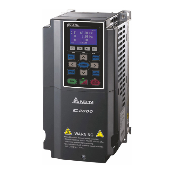
Delta C2000 series User Manual
Classical field oriented.
control ac motor drive
Hide thumbs
Also See for C2000 series:
- User manual (936 pages) ,
- Manual (22 pages) ,
- Product application (5 pages)
Table of Contents
Advertisement
Quick Links
Advertisement
Table of Contents

Related Manuals for Delta C2000 series


Summary of Contents for Delta C2000 series
- Page 2 30 °C. Storage longer than one year is not recommended, it could result in the degradation of the electrolytic capacitors. NOTE The content of this manual may be revised without prior notice. Please consult our distributors or download the most updated version at http://www.delta.com.tw/industrialautomation...
-
Page 3: Table Of Contents
Table of Contents CHAPTER 1 INTRODUCTION ....................1-1 CHAPTER 2 INSTALLATION ....................2-1 CHAPTER 3 UNPACKING ......................3-1 CHAPTER 4 WIRING ........................4-1 CHAPTER 5 MAIN CIRCUIT TERMINALS ................5-1 CHPATER 6 CONTROL TERMINALS ..................6-1 CHAPTER 7 OPTIONAL ACCESSORIES ................7-1 CHAPTER 8 OPTION CARDS .................... -
Page 4: Group
Summary of Updates|C2000 Series Publication History The following changes summarize the differences to the C2000 Simplified Manual, Version 5011694702. Chatpers Changes Detail [Table of Content] New Chapters: • Chapter 2 Installation • Chapter 7 Optional Accessories • Chapter 12 Description of Parameter Settings •... - Page 5 Pr.05-05~05-09, 05-018~05-21 Group 06 Pr.06-48, 06-69, 06-70 Group 07 Pr.07-05 Group 08 Pr.08-00, 08-06 Group 09 Pr.09-04, 09-31, 09-43 Group 10 Pr.10-31~10-42 Group 11 Pr.11-02, 11-13, 11-39, 11-42 Pr. 02-55~02-58, [13 Warning Codes] PLra [14 Fault Codes and Fault code: Descriptions] “ryF”...
- Page 6 Heavy Duty: 3PH 0- 480 V 2.9A 2.3KVA 1 HP Frequ ency Range FREQUENCY RANGE: Normal Duty: 0-600Hz Heavy Duty: 0-300Hz Firmware Versio n VX.XX Version: Certifications Encl osure type (IPXX) Serial Number 007 C4 3A7T9300 002 DELTA E LEC TRONIC S. INC . MAD E IN XXXXXXX...
- Page 7 Chapter 1 Introduction|C2000 Series Model Name VFD 007 C 43 A Versi on ty pe Inpu t vo ltage 23:2 30V 3-PHASE 43:4 60V 3-PHASE C2000 serie s Appli cabl e motor capacity 007 :1HP(0.75 kW)~ 3350:475HP(335kW Refer to the specifications for detail s...
- Page 8 Chapter 1 Introduction|C2000 Series RFI Jumper RFI Jumper: The AC motor drive may emit the electrical noise. The RFI jumper is used to suppress the interference (Radio Frequency Interference) on the power line. Frame A~C Screw Torque: 8 ~10kg-cm(6.9-8.7 lb -in.) Loosen the screws and remove the MOV-PLATE.
- Page 9 Chapter 1 Introduction|C2000 Series Frame D~H Remove the MOV-PLATE by hands, no screws need to be loosen. Main power isolated from earth: If the AC motor drive is supplied from an isolated power (IT power), the RFI jumper must be cut off. Then the RFI capacities (filter capacitors) will be disconnected from ground to prevent circuit damage (according to IEC 61800-3) and reduce earth leakage current.
- Page 10 Chapter 1 Introduction|C2000 Series Dimensions Frame A VFD007C23A; VFD007C43A/E; VFD015C23A; VFD015C43A/E; VFD022C23A; VFD022C43A/E; VFD037C23A; VFD037C43A/E; VFD040C43A/E; VFD055C43A/E Unit: mm [inch] Frame Φ1 Φ2 Φ3 130.0 250.0 170.0 116.0 236.0 45.8 22.2 34.0 28.0 [5.12] [9.84] [6.69] [4.57] [9.29] [1.80] [0.24] [0.87]...
- Page 11 Chapter 1 Introduction|C2000 Series Frame B VFD055C23A; VFD075C23A; VFD075C43A/E; VFD110C23A; VFD110C43A/E; VFD150C43A/E See Detail A See Detail B Detail A (Mounting Hole) Detail B (Mounting Hole) Unit: mm [inch] Frame Φ1 Φ2 Φ3 190.0 320.0 190.0 173.0 303.0 77.9 22.2 34.0...
- Page 12 Chapter 1 Introduction|C2000 Series Frame C VFD150C23A; VFD185C23A; VFD185C43A/E; VFD220C23A; VFD220C43A/E; VFD300C43A/E See Detail A See Detail B Detail A (Mounting Hole) Detail B (Mounting Hole) Unit: mm [inch] Frame Φ1 Φ2 Φ3 250.0 400.0 210.0 231.0 381.0 92.9 22.2 34.0...
- Page 13 Chapter 1 Introduction|C2000 Series Frame D D1: VFD300C23A; VFD370C23A; VFD370C43A; VFD450C43A; VFD550C43A; VFD750C43A SEE DETAIL A SEE DETAIL B DETAIL B DETAIL A (MOUNTING HOLE) (MOUNTING HOLE) Unit: mm [inch] Φ1 Φ2 Φ3 Frame 330.0 275.0 285.0 550.0 525.0 492.0 107.2...
- Page 14 Chapter 1 Introduction|C2000 Series D2: VFD300C23E; VFD370C23E; VFD370C43E; VFD450C43E; VFD550C43E; VFD750C43E SEE DETAIL A SEE DETAIL B DETAIL A DETAIL B (MOUNTING HOLE) (MOUNTING HOLE) Unit: mm [inch] Frame Φ1 Φ2 Φ3 330.0 688.3 275.0 285.0 550.0 525.0 492.0 107.2 16.0...
- Page 15 Chapter 1 Introduction|C2000 Series Frame E E1: VFD450C23A; VFD550C23A; VFD750C23A; VFD900C43A; VFD1100C43A Unit: mm [inch] Frame S1, S2 ψ1 ψ2 ψ3 370.0 300.0 335.0 560.0 528.0 143.0 18.0 13.0 18.0 [14.57] [11.81] [13.19 [23.19] [22.05] [20.80] [5.63] [0.71] [0.51] [0.71]...
- Page 16 Chapter 1 Introduction|C2000 Series Frame E E2: VFD450C23E; VFD550C23E; VFD750C23E; VFD900C43E; VFD1100C43E Unit: mm [inch] Frame S1, S2 ψ1 ψ2 ψ3 370.0 715.8 300.0 335.0 560.0 528.0 143.0 18.0 13.0 18.0 22.0 34.0 92.0 [14.57] [28.18] [11.81] [13.19 [23.19] [22.05] [20.80]...
- Page 17 Chapter 1 Introduction|C2000 Series Frame F F1: VFD900C23A; VFD1320C43A; VFD1600C43A See Detail A See Detail B Detail A (Mounting Hole) Detail B (Mounting Hole) Unit: mm [inch] Frame 420.0 300.0 380.0 800.0 770.0 717.0 124.0 18.0 13.0 25.0 18.0 [16.54] [11.81]...
- Page 18 Chapter 1 Introduction|C2000 Series Frame F F2: VFD900C23E; VFD1320C43E; VFD1600C43E See Detail A See Detail B Detail A (Mounting Hole) Detail B (Mounting Hole) Unit: mm [inch] Frame 420.0 940.0 300.0 380.0 800.0 770.0 717.0 124.0 18.0 13.0 25.0 18.0 [16.54]...
- Page 19 Chapter 1 Introduction|C2000 Series Frame G G1: VFD1850C43A; VFD2200C43A Unit: mm [inch] Frame ψ1 ψ2 ψ3 500.0 397.0 440.0 1000.0 963.0 913.6 13.0 26.5 27.0 [19.69] [15.63] [217.32] [39.37] [37.91] [35.97] [0.51] [1.04] [1.06] 1-14...
- Page 20 Chapter 1 Introduction|C2000 Series Frame G G2: VFD1850C43E; VFD2200C43E Unit: mm [inch] Frame ψ1 ψ2 ψ3 500.0 1240.2 397.0 440.0 1000.0 963.0 913.6 13.0 26.5 27.0 22.0 34.0 117.5 [19.69] [48.83] [15.63] [217.32] [39.37] [37.91] [35.97] [0.51] [1.04] [1.06] [0.87] [1.34]...
- Page 21 Chapter 1 Introduction|C2000 Series Frame H H1: VFD2800C43A; VFD3150C43A; VFD3550C43A Unit: mm [inch] Frame 700.0 398.0 290.0 1346.6 1435.0 630.0 1403.0 [56.5] [24.8] [55.24] [27.56] [15.67] [11.42] [53.02] Frame ψ1 ψ2 ψ3 45.0 13.0 26.5 25.0 [1.77] [0.51] [1.04] [0.98]...
- Page 22 Chapter 1 Introduction|C2000 Series Frame H H2: VFD2800C43E-1; VFD3150C43E-1; VFD3550C43E-1 Unit: mm [inch] Frame 700.0 1745.0 404.0 630.0 760.0 800.0 1729.0 500.0 630.0 1701.6 [19.69] [24.8] [66.99] [27.56] [68.70] [15.91] [24.8] [29.92] [31.5] [68.07] Frame Φ Φ Φ 51.0 38.0 65.0...
- Page 23 Chapter 1 Introduction|C2000 Series Frame H H3: VFD2800C43E; VFD3150C43E; VFD3550C43E Unit: mm [inch] Frame 700.0 1745.0 404.0 630.0 760.0 800.0 1729.0 500.0 630.0 1701.6 [27.56] [68.70] [15.91] [24.8] [19.69] [24.8] [29.92] [31.5] [68.07] [66.99] Frame Φ Φ Φ 51.0 38.0 65.0...
- Page 24 Chapter 1 Introduction|C2000 Series Digital Keypad KPC-CC01 1-19...
- Page 25 Chapter 2 Installation|C2000 Series Chapter 2 Installation Minimum Mounting Clearance and Installation NOTE Prevent fiber particles, scraps of paper, shredded wood saw dust, metal particles, etc. from adhereing to the heat sink Install the AC motor drive in a metal cabinet. When installing one drive below another one, use a metal separation between the AC motor drives to prevent mutual heating and to prevent the risk of fire accident.
- Page 26 Chapter 2 Installation|C2000 Series Multiple drives, side-by-side installation (Frame D, E, F) Install metal separation between the drives. Multiple drives side-by-side installation and in rows (Frame A,B,C ) Ta: Frame A~G Ta*: Frame H When installing one AC motor drive below another one (top-bottom installation), use a metal separation between the drives to prevent mutual heating.
- Page 27 Chapter 2 Installation|C2000 Series Frame E VFD450C23A/E; VFD550C23A/E; VFD750C23A/E; VFD900C43A/E; VFD1100C43A/E Frame F VFD900C23A/E; VFD1320C43A/E; VFD1600C43A/E Frame G VFD1850C43A; VFD2200C43A; VFD1850C43E; VFD2200C43E Frame H VFD2800C43A; VFD3150C43A; VFD3550C43A; VFD2800C43E-1; VFD3150C43E-1; VFD3550C43E-1;VFD2800C43E; VFD3150C43E; VFD3550C43E NOTE 1. The minimum mounting clearances stated in the table above applies to AC motor drives frame A to D. A drive fails to follow the minimum mounting clearances may cause the fan to malfunction and heat dissipation problem.
- Page 28 Chapter 2 Installation|C2000 Series VFD037C43A/E VFD040C43A/E VFD055C43A/E VFD075C43A/E VFD110C43A/E VFD150C43A/E VFD185C43A/E VFD220C43A/E VFD300C43A/E VFD370C43A/E VFD450C43A/E 1147 VFD550C43A/E 1156 1413 Power dissipation of AC motor Air flow rate for cooling drive Flow Rate (cfm) Flow Rate (m /hr) Power Dissipation Model No.
-
Page 29: Chapter 2 Installation
Chapter 2 Installation|C2000 Series Derating Curve Diagram of Normal Duty (Pr.00-16=0) Set Pr.06-55 = 1 Set Pr.06-55 = 0 or 2 (40℃: UL open-type) Set Pr.06-55 = 0 or 2 (30℃: UL type1 or open type_size by size) (50℃: UL open-type) (40℃:UL type1 or open type_size by size) - Page 30 Chapter 2 Installation|C2000 Series Derating Curve Diagram of Heavy Duty (Pr.00-16=1) Set Pr.06-55 = 1 Set Pr.06-55 = 0 or 2 (40℃: UL open-type) Set Pr.06-55 = 0 or 2 (30℃: UL type1 or open type_size by size) (50℃: UL open-type) (40℃: UL type1 or open type_size by size)
-
Page 31: Chapter 3 Unpacking
Chapter 3 Unpacking|C2000 Series Chapter 3 Unpacking The AC motor drive should be kept in the shipping carton or crate before installation. In order to retain the warranty coverage, the AC motor drive should be stored properly when it is not to be used for an extended period of time. - Page 32 Chapter 3 Unpacking|C2000 Series Lift the drive by hooking the lifting hole. It is now Loosen the 10 screws on the pallet, remove the ready for installation. wooden plate. Lift the drive by hooking the lifting hole. It is now ready for installation.
- Page 33 Chapter 3 Unpacking|C2000 Series Remove the crate cover, EPEs and manual. Remove the crate cover, EPEs, rubbers and manual. Loosen the 8 screws on the pallet as shown in the Loosen the 10 screws on the pallet and remove the following figure.
- Page 34 Chapter 3 Unpacking|C2000 Series Frame F Crate 1 (VFDXXXCXXA) Crate 2 (VFDXXXCXXE) Remove the 6 clips on the side of the crate with a Remove the 6 clips on the side of the crate with a flat-head screwdriver. (As shown in figure below.) flat-head screwdriver.
- Page 35 Chapter 3 Unpacking|C2000 Series Lift the drive by hooking the lifting hole. It is now Lift the drive by hooking the lifting hole. It is now ready for installation ready for installation. Frame G Crate 1 (VFDXXXCXXA) Crate 2 (VFDXXXCXXE)
- Page 36 Chapter 3 Unpacking|C2000 Series Loosen the 5 screws as shown in following figure: Loosen the 9 screws and remove the wooden plate. wood plate1 wood plate2 wood plate3 wood plate5 wood plate4 Lift the drive by hooking the lifting hole. It is now Lift the drive by hooking the lifting hole.
- Page 37 Chapter 3 Unpacking|C2000 Series Remove the crate cover, EPEs and manual. Remove the crate cover, EPEs, rubbers and manual. Loosen the 6 screws on the top then remove 6 Loosen the 6 screws on the top then remove 6 metal washers and 6 plastic washers as shown in metal washers and 6 plastic washers as shown in figure below.
- Page 38 Chapter 3 Unpacking|C2000 Series Secure the drive from the external. (Skip to the next step if this situation does not apply to you.) Loosen 8 of M8 screws on the both sides and place the 2 plates that were removed from the last step.
- Page 39 Chapter 3 Unpacking|C2000 Series Remove the crate cover, EPEs, rubber and manual. Loosen the 6 screws on the cover, remove 6 metal washers and 6 plastic washers as shown in below: Loosen 6 of the M6 screws on the side and removes the 2 plates, as shown in following figure. The...
- Page 40 Chapter 3 Unpacking|C2000 Series Secure the drive from the internal. Secure the drive from the external. Loosen 18 of the M6 screws and remove the top Loosen 8 of the M8 screws on the both sides and cover as shown in figure 2. Mount the cover (figure...
- Page 41 Chapter 3 Unpacking|C2000 Series Lift the drive by hooking the lifting hole. It is now ready for installation. Frame H Secure the drive (VFDXXXCXXA) Screw: M12*6 Torque: 340-420kg-cm [295.1-364.6lb-in.] 3-11...
- Page 42 Chapter 3 Unpacking|C2000 Series (VFDXXXCXXE) & (VFDXXXCXXE-1) Secure the drive from the internal. Screw: M12*8 Torque: 340-420kg-cm [295.1-364.6lb-in.] Secure the drive from the external. Screw: M12*8 Torque: 340-420kg-cm [295.1-364.6lb-in.] 3-12...
- Page 43 Chapter 3 Unpacking|C2000 Series The Lifting Hook The arrows indicate the location of the lifting holes of frame D to H, as shown in figure below: Figure 1 Figure 2 Figure 3 Figure 4 Figure 5 3-13...
- Page 44 Chapter 3 Unpacking|C2000 Series Ensure the lifting hook properly goes through the Ensure the angle between the lifting holes and the lifting hole, as shown in the following diagram. lifting device is within the specification, as shown (Applicable to Frame D~E) in the following figure.
- Page 45 Chapter 3 Unpacking|C2000 Series Weight VFDXXXXCXXA VFDXXXXCXXE 37.6 kg(82.9 Ibs.) 40 kg(88.2 Ibs.) VFDXXXXCXXA VFDXXXXCXXE 63.6 kg(140.2 Ibs.) 66 kg(145.5 Ibs.) VFDXXXXCXXA 85kg(187.2 Ibs.) 88kg(193.8 Ibs.) VFDXXXXCXXE VFDXXXXCXXA 130kg(286.5 Ibs.) VFDXXXXCXXE 138kg(303.9 lbs) VFD2800C43A; VFD3150C43A; VFD3550C43A 235kg (518.1lbs) H2: VFD2800C43E-1; VFD3150C43E-1; VFD3550C43E-1 257kg (566.6lbs)
- Page 46 Chapter 3 Unpacking|C2000 Series H3: VFD2800C43E; VFD3150C43E; VFD3550C43E 263kg (579.8lbs) 3-16...
-
Page 47: Drives
Chapter 4 Wiring|C2000 Series Chapter 4 Wiring After removing the front cover, examine if the power and control terminals are clearly noted. Please read following precautions before wiring. Make sure that power is only applied to the R/L1, S/L2, T/L3 terminals. Failure to comply may result in damage to the equipments. - Page 48 Chapter 4 Wiring|C2000 Series Wiring Diagram for Frame A~C DC choke Br ak e res istor (optional) * It pr ovides 3-phase power (optional) Jumper F us e/NF B(No F use B reaker) R (L1) R(L1) Motor U(T 1) S(L2)
- Page 49 Chapter 4 Wiring|C2000 Series Wiring Diagram for Fra me D a nd Frames Abov e * It pr ovides 3-phase power Please ref er to f igure 3 -/DC - +/D C+ F us e/NF B(No F use Breaker) R(L1)
- Page 50 Chapter 4 Wiring|C2000 Series Figure 1 In put power t erminals for frame G a nd H It prov ides 12 -p ulse power Prov ides 3-p has e po we r R/L11 Fus e or NFB (non-f use break er)
- Page 51 NOTE Common DC Bus can only be applied to the drives with same power range. If in your case the drives are in different power range, please contact with us (Delta Industrial Automation Business Unit).
-
Page 52: Chapter 5 Main Circuit Terminals
Chapter 5 Main Circuit Terminals|C2000 Series Chapter 5 Main Circuit Terminals Main Circuit Diagram 1 For frame A~C Brake resis tor (optio nal) * Provid e 3-ph ase input power Jumper Fuse/NFB(No F use Breaker) R(L1) U(T1) Motor R(L1) S(L2) - Page 53 Chapter 5 Main Circuit Terminals|C2000 Series Main Circuit Diagram 3 Po we r input te rm in als o f f rame G and H It prov ides 12 -pulse rec tifier Provides 3-p has e po we r Fus e or NFB (non-f us e brea ker)
- Page 54 Chapter 5 Main Circuit Terminals|C2000 Series Run/stop AC motor drives by RUN/STOP command via control terminals or keypad. If you still need to run/stop AC motor drives by turning power ON/OFF, it is recommended to do so only ONCE per hour.
- Page 55 Chapter 5 Main Circuit Terminals|C2000 Series brake torque. When the terminals +1, +2 and - are not used, please leave the terminals open. DO NOT connect [+1, -], [+2, -], [+1/DC+, -/DC-] or brake resistor directly to prevent drive damage.
- Page 56 Chapter 5 Main Circuit Terminals|C2000 Series 5-1 Main Circuit Terminals Frame A Main circuit terminals: R/L1, S/L2, T/L3, U/T1, V/T2, W/T3, , B1, B2, +1, +2, - Max. Wire Torque Models Min. Wire Gauge Gauge (±10%) VFD007C23A 14 AWG (2.1mm VFD015C23A 12 AWG (3.3mm...
- Page 57 Chapter 5 Main Circuit Terminals|C2000 Series Frame B Main circuit terminals: R/L1, S/L2, T/L3, U/T1, V/T2, W/T3, , B1, B2, +1, +2, - Max. Wire Torque Models Min. Wire Gauge Gauge (±10%) VFD055C23A 8 AWG (8.4mm VFD075C23A 6 AWG (13.3mm VFD110C23A 4 AWG (21.2mm...
- Page 58 Chapter 5 Main Circuit Terminals|C2000 Series Frame C Main circuit terminals: R/L1, S/L2, T/L3, U/T1, V/T2, W/T3, , B1, B2, +1, +2, - Max. Wire Torque Models Min. Wire Gauge Gauge (±10%) VFD150C23A 1 AWG (42.4mm VFD185C23A 1/0 AWG (53.5mm VFD220C23A 1/0 AWG (53.5mm...
- Page 59 Chapter 5 Main Circuit Terminals|C2000 Series Frame D Main circuit terminals: R/L1, S/L2, T/L3, U/T1, V/T2, W/T3, , +1/DC+, -/DC- Max. Wire Torque Models Min. Wire Gauge Gauge (±10%) VFD300C23A 4/0 AWG (107mm VFD370C23A 250MCM (127mm VFD370C43A 300MCM 1/0 AWG (53.5mm...
- Page 60 Chapter 5 Main Circuit Terminals|C2000 Series Frame E Main circuit terminals: R/L1, S/L2, T/L3, U/T1, V/T2, W/T3, , +1/DC+, -/DC- Max. Wire Torque Models Min. Wire Gauge Gauge (±10%) VFD450C23A 1/0AWG*2 (53.5mm VFD550C23A 3/0AWG*2 (85mm 300MCM*2 VFD750C23A 4/0 AWG*2 (107mm...
- Page 61 Chapter 5 Main Circuit Terminals|C2000 Series Frame F Main circuit terminals: R/L1, S/L2, T/L3, U/T1, V/T2, W/T3, +1/DC+, -/DC- Max. Wire Torque Models Min. Wire Gauge Gauge (±10%) VFD900C23A 300MCM*2 (152mm 300MCM*2 VFD1320C43A 4/0 AWG*2 (107mm (152mm VFD1600C43A 300MCM*2 (152mm 200kg-cm (173 lb-in.)
- Page 62 Chapter 5 Main Circuit Terminals|C2000 Series Frame G Main circuit terminals: R/L11, R/L12, S/L21, S/L22, T/L31, T/L32 Max. Wire Torque Models Min. Wire Gauge Gauge (±10%) VFD1850C43A 2/0AWG*4 (67.4mm VFD2200C43A 3/0AWG*4 (85mm 300MCM*4 200kg-cm (173 lb-in.) (152mm VFD1850C43E 1/0AWG*4 (53.5mm (19.62Nm)
- Page 63 Chapter 5 Main Circuit Terminals|C2000 Series Frame H Main circuit terminals: R/11,R12,S/21,S/22,T/31,T/32, V/T2, W/T3, +1/DC+, U/T1, -/DC- Max. Wire Torque Models Min. Wire Gauge Gauge (±10%) VFD2800C43A 4/0 AWG*4 (107mm VFD3150C43A 300MCM*4 (152mm VFD3550C43A 300MCM*4 (152mm VFD2800C43E-1 3/0 AWG*4 (85mm...
- Page 64 Chapter 6 Control Terminals|C2000 Series Chapter 6 Control Terminals Please remove the top cover before wiring the multi-function input and output terminals, The drive appearances shown in the figures are for reference only, a real drive may look different. Remove the cover for wiring. Frame A~H Frame A&B...
- Page 65 Chapter 6 Control Terminals|C2000 Series Frame G Screw torque: 12~15Kg-cm [10.4~13lb-in.] To remove the cover, lift it slightly and pull outward Frame H Screw torque: 14~16Kg-cm [12.15~13.89lb-in.] To remove the cover, lift it slightly and pull outward 0-1 0V 0-1 0V...
- Page 66 Chapter 6 Control Terminals|C2000 Series Wiring precautions: Reserves 5mm and properly install the wire into the terminal; fasten the installation by a slotted screwdriver. If the wire is stripped, sort the wire before install into the terminal. Flathead screwdriver: blade width 3.5mm, tip thickness 0.6mm In the figure above, the factory setting for S1-SCM is short circuit.
- Page 67 Chapter 6 Control Terminals|C2000 Series Terminals Terminal Function Factory Setting (NPN mode) Analog frequency setting: -10Vdc 20mA Potentiometer power supply -10V Analog voltage input +10V AVI circuit Impedance: 20kΩ Range: 4 ~ 20mA/0~10V =0~Max. Output Frequency (Pr.01-00) AVI switch, factory setting is 0~10V...
- Page 68 Chapter 6 Control Terminals|C2000 Series Analog input terminals (AVI, ACI, AUI, ACM) Analog input signals are easily affected by external noise. Use shielded wiring and keep it as short as possible (<20m) with proper grounding. If the noise is inductive, connecting the shield to terminal ACM can bring improvement.
-
Page 69: Chapter 7 Optional Accessories
Chapter 7 Optional Accessories|C2000 Series Chapter 7 Optional Accessories The optional accessories listed in this chapter are available upon request. Installing additional accessories to your drive would substantially improves the drive’s performance. Please select an applicable accessory according to your need or contact the local distributor for suggestion. - Page 70 Chapter 7 Optional Accessories |C2000 Series All Brake Resistors and Brake Units Used in AC Motor Drives 230V Applicable 125%Braking Torque 10%ED Max. Brake Torque Motor Braking Brake Resistor value Total Min. Max. Total Peak Braking Resistor series HP kW...
- Page 71 Chapter 7 Optional Accessories|C2000 Series 460V Applicable 125%Braking Torque 10%ED Max. Brake Torque Motor Braking Resistor Total Min. Max. Total Peak Torque Brake Braking Resistor series for value spec. HP kW Braking Resistor Braking Power (kg-m) Unit each Brake Unit...
- Page 72 If damage to the drive or other equipment is due to the fact that the brake resistors and brake modules in use are not provided by Delta, the warranty will be void. Take into consideration the safety of the environment when installing the brake resistors. If the minimum resistance value is to be utilized, consult local dealers for the calculation of Watt figures.
- Page 73 Chapter 7 Optional Accessories|C2000 Series Non-fuse Circuit Breaker Comply with UL standard: Per UL 508, paragraph 45.8.4, part a, The rated current of the breaker shall be 2~4 times of the maximum rated input current of AC motor drive. 3-phase 230V...
- Page 74 Chapter 7 Optional Accessories |C2000 Series Fuse Specification Chart Use only the fuses comply with UL certificated. Use only the fuses comply with local regulations. Input Currnet I(A) Line Fuse 230V Model Heavy Duty Normal Duty I (A) Bussmann P/N...
- Page 75 Chapter 7 Optional Accessories|C2000 Series AC Reactor When the AC Motor Drive is connected directly to a large-capacity power transformer (600kVA or above) or when a phase lead capacitor is switched, excess peak currents may occur in the power input circuit due to the load changes and the converter section may be damaged. To avoid this, it is recommend to use a serial connected AC input reactor(6%) at the AC Motor Drive mains input side to reduce the current and improve the input power efficiency.
- Page 76 Chapter 7 Optional Accessories |C2000 Series Applications for AC Reactor Connected in input circuit Application 1 When more than one AC motor drive is connected to the same mains power, and one of them is ON during operation. Problem: When applying power to one of the AC motor drive, the charge current of the capacitors may cause voltage dip.
- Page 77 Chapter 7 Optional Accessories|C2000 Series Zero Phase Reactors RF220X00A UNIT: mm (inch) Diagram A Recommended Cable Wind each wire around the core for 4 times. The reactor Wire Size (mm Wiring type Qty. must be placed at the AC motor drive output side as...
- Page 78 Chapter 7 Optional Accessories |C2000 Series DC Reactor 230V DC Choke Inductance(mh) Input Voltage DC Amps 0.75 3.43 1.83 1.37 230Vac 0.78 50/60Hz 0.61 3-Phase 0.42 0.31 18.5 0.26 0.22 460V DC Choke Input Voltage DC Amps Inductance(mh) 0.75 9.77 7.12...
- Page 79 Chapter 7 Optional Accessories|C2000 Series EMI Filter Applicable Model Reference Website EMI Filter VFD007C23A; http://www.dem-uk.com/roxburgh/products/industrial_emc_filters/three_phase_industrial_ VFD015C23A; KMF325A mains_filters_high_performance/ VFD022C23A; VFD037C23A; KMF325A Three Phase Industrial Mains Filters - High Performance 25 Amps http://www.dem-uk.com/roxburgh/products/industrial_emc_filters/three_phase_industrial_ VFD055C23A; VFD075C23A; KMF370A mains_filters_high_performance/ VFD110C23A; KMF370A Three Phase Industrial Mains Filters - High Performance 70 Amps http://www.dem-uk.com/roxburgh/products/industrial_emc_filters/three_phase_industrial_...
- Page 80 All electrical equipment, including AC motor drives, will generate high-frequency/low-frequency noise and will interfere with peripheral equipment by radiation or conduction when in operation. By using an EMI filter with correct installation, much interference can be eliminated. It is recommended to use DELTA EMI filter to have the best interference elimination performance.
- Page 81 Chapter 7 Optional Accessories|C2000 Series Saddle on both ends Saddle on one end Figure 2 The length of motor cable When motor is driven by an AC motor drive of PWM type, the motor terminals will experience surge voltages easily due to components conversion of AC motor drive and cable capacitance.
- Page 82 Chapter 7 Optional Accessories |C2000 Series Digital Keypad KPC-CE01 : LED Disp lay D ispla y freq uen cy, cu rre nt, vo ltag e and erro r etc. : Status Indicator F: Fre que ncy C omma nd H: Outp ut Frequ ency...
- Page 83 Chapter 7 Optional Accessories|C2000 Series Dimension RJ45 Extension Lead for Digital Keypad Part # Description CBC-K3FT 3 feet RJ45 extension lead (approximately 0.9m) CBC-K5FT 5 feet RJ45 extension lead (approximately 1.5 m) CBC-K7FT 7 feet RJ45 extension lead (approximately 2.1 m)
- Page 84 Chapter 7 Optional Accessories |C2000 Series Panel Mounting (MKC-KPPK) For MKC-KPPK model, user can choose wall mounting or embedded mounting, protection level is IP56. Applicable to the digital keypads (KPC-CC01 & KPC-CE01). Wall Mounting Embedded Mounting accessories*1 accessories*2 Screw *4 ~M4*p 0.7 *L8mm Screw *4 ~M4*p 0.7 *L8mm...
- Page 85 Chapter 7 Optional Accessories|C2000 Series 7-17...
- Page 86 Chapter 7 Optional Accessories |C2000 Series Conduit Box Kit Appearance Frame D Frame E Applicable models Applicable models VFD300C23A/23E; VFD370C23A/23E;VFD370C43A/43E; VFD450C23A/23E; VFD550C23A/23E; VFD750C23A/23E; VFD450C43A/43E; VFD550C43A/43E; VFD750C43A/43E VFD900C43A/43E; VFD1100C43A/43E Model number『MKC-DN1CB』 Model number『MKC-EN1CB』 ITEM Description Qty. ITEM Description Qty. 1 Screw M5*0.8*10L 1 Screw M5*0.8*10L...
- Page 87 Chapter 7 Optional Accessories|C2000 Series Conduit Box Installation Frame D Loosen the cover screws and press the tabs on each side of the cover to remove the cover, as shown in the following figure. Screw torque: 10~12kg-cm (8.66~10.39Ib-in) Remove the 5 screws shown in the following figure. Screw torque: 24~26kg-cm (20.8~22.6Ib-in).
- Page 88 Chapter 7 Optional Accessories |C2000 Series Frame E 1. Loosen the 4 cover screws and lift the cover; Screw torque: 12~ 15 kg-cm (10.4~13Ib-in). 2. Fasten the 6 screws shown in the following figure and place the cover back to the original position. Screw torque: 24~26kg-cm (20.8~22.6Ib-in).
- Page 89 Chapter 7 Optional Accessories|C2000 Series Frame F Loosen the cover screws and press the tabs on each side of the cover to remove the cover, as shown in the following figure. Screw torque: 14~16kg-cm (12.2~13.9Ib-in). Install the conduit box by fastens the 4 screws, as shown in the following figure.
- Page 90 Chapter 7 Optional Accessories |C2000 Series Frame G On the conduit box, loosen 7 of the cover screws and remove the cover. On the drive, loosen 4 of the cover screws and press the tabs on each side of the cover to remove the cover, as shown in the following figure.
- Page 91 Chapter 7 Optional Accessories|C2000 Series Fasten all the screws. Screw torque: 25~30kg-cm (20.8~30Ib-in). Place the cover back to the top and fasten the screws (as shown in the figure). Screw torque: 12~15kg-cm (10.4~13Ib-in). 7-23...
- Page 92 Chapter 7 Optional Accessories |C2000 Series Fan Kit Frames of the fan kit Frame A Model『MKC-AFKM』 Applicable Model VFD015C23A; VFD022C23A; VFD037C23A;VFD022C43A/43E; VFD037C43A/43E;VFD040C43A/43E; VFD055C43A/43E Frame B Model『MKC-BFKM1』 Applicable Model VFD055C23A; VFD075C43A/43E Frame B Model 『MKC-BFKM2』 Applicable Model VFD075C23A; VFD110C23A; VFD110C43A/43E; VFD150C43A/43E Frame B Model 『MKC-BFKB』...
- Page 93 Chapter 7 Optional Accessories|C2000 Series Frame C Model 『MKC-CFKB2』 Applicable Model VFD185C43A/43E; VFD220C43A/43E;VFD300C43A/43E Frame D Model 『MKC-DFKM』 Model 『MKC-DFKB』 Applicable Model VFD300C23A/23E; VFD370C23A/23E; VFD370C43A/43E; VFD450C43A/43E; VFD550C43A/43E; VFD750C43A/43E Frame E Model 『MKC-EFKM1』 Applicable Model VFD450C23A/23E; VFD550C23A/23E Frame E Model『MKC-EFKM2』 Applicable Model VFD750C23A/23E;...
- Page 94 Chapter 7 Optional Accessories |C2000 Series Frame F Model 『MKC-FFKM』 Applicable Model VFD900C23A/23E; VFD1320C43A/43E; VFD1600C43A/43E Frame F Model 『MKC-FFKB』 Applicable Model VFD900C23A/23E; VFD1320C43A/43E; VFD1600C43A/43E Frame G Model 『MKC-GFKM』 Applicable Model VFD1850C43A/43E; VFD2200C43A/43E Frame H Model 『MKC-HFKM』 Applicable Model VFD2800C43A/43E; VFD3150C43A/43E; VFD3550C43A/43E;...
- Page 95 Chapter 7 Optional Accessories|C2000 Series Fan Removal Frame A Applicable model VFD015C23A; VFD022C23A; VFD022C43A/43E; VFD037C23A; VFD037C43A/43E; VFD040C43A/43E; VFD055C43A/43E Press the tabs on both side of the fan to successfully Disconnect the power terminal before removing the fan. remove the fan. (The arrow) (As shown below.)
- Page 96 Chapter 7 Optional Accessories |C2000 Series (Figure 1) Loosen screw 1 and screw 2, press the on the (Figure 2) Loosen screw 3 and screw 4, press the tab on right and the left to remove the cover, follow the direction the right and the left to remove the cover.
- Page 97 Chapter 7 Optional Accessories|C2000 Series Loosen screw 1 and screw 2 (as shown in the figure below), and disconnect fan power before removing the fan. Screw torque: 24~26kg-cm (20.8~25.6in-lbf). Frame F Applicable model VFD900C23A/23E; VFD1320C43A/43E; VFD1600C43A/43E; Fan model『MKC-FFKM』 Loosen the screws and removes the fan (as shown in figure below). Screw torque: 24~26kg-cm (20.8~22.6Ib-in』...
- Page 98 Chapter 7 Optional Accessories |C2000 Series (3) Loosen the screws and remove the fan. (As shown in the figure below) Screw torque: 24~26kg-cm (20.8~22.6Ib-in). Frame G Applicable model VFD1800C43A/43E; VFD2200C43A/43E; (2) For 1~8 shown in the figure: Loosen the screws Fan model『MKC-GFKM』...
- Page 99 Chapter 7 Optional Accessories|C2000 Series Frame H Applicable model VFD2800C43A/43E; VFD3150C43A/43E; VFD3550C43A/43E (2) Loosen the screw and remove the top cover. Fan model 『MKC-HFKM』 Screw torque: 24~26kg-cm (20.8~22.6Ib-in). (1) Loosen the screw and remove the top cover. Screw torque: 14~16kg-cm (12.2~13.9Ib-in) (3) Disconnect the fan.
- Page 100 Chapter 7 Optional Accessories |C2000 Series Flange Mounting Kit Applicable Models, Frame A~F Frame A 『MKC-AFM1』 Applicable model VFD015C23A; VFD022C23A; VFD022C43A/43E Screw 1 *4 M3*P 0.5; L=6mm Screw 2*8 M6*P 1.0; L=16mm Accessories 1*1 Accessories 2*2 Accessories 3*2 『MKC-AFM』 Applicable model VFD007C23A;...
- Page 101 Chapter 7 Optional Accessories|C2000 Series 『MKC-AFM1』Installation Install accessory 1 by fastening 4 of the screw 1(M3). Screw torque: 6~8kg-cm (5.21~6.94Ib-in). Install accessory 2&3 by fastening 2 of the screw 2(M6). Screw torque: 25~30kg-cm (5.21~6.94Ib-in). Install accessory 2&3 by fastening 2 of the screw 2(M6). Screw torque: 25~30kg-cm (5.21~6.94Ib-in).
- Page 102 Chapter 7 Optional Accessories |C2000 Series Install accessory 1& 2 by fastening 2 of the screw 1(M3). Screw torque: 25~30kg-cm (5.21~6.94Ib-in). (As shown in following figure) Plate installation, place 4 of the screw 2 (M6) through accessory 1&2 and the plate then fasten the screws.
- Page 103 Chapter 7 Optional Accessories|C2000 Series Frame B 『MKC-BFM』 Applicable model VFD055C23A; VFD075C23A; VFD110C23A; VFD075C43A/43E; VFD110C43A/43E; VFD150C43A/43E Screw 1 *4 ~ M8*P 1.25; Screw 2*6 ~ M6*P 1.0; Accessories 1*2 Accessories 2*2 Cutout dimension Unit: mm [inch] 7-35...
- Page 104 Chapter 7 Optional Accessories |C2000 Series 『MKC-BFM』Installation Install accessory 1& 2 by fastening 4 of the screw 1(M8). Screw torque: 40~45kg-cm (34.7~39.0Ib-in). (As shown in the following figure) Plate installation, place 6 of the screw 2 (M6) through accessory 1&2 and the plate then fasten the screws.
- Page 105 Chapter 7 Optional Accessories|C2000 Series Frame C 『MKC-CFM』 Applicable model VFD150C23A; VFD185C23A; VFD220C23A; VFD185C43A/43E; VFD220C43A/43E; VFD300C43A/43E Screw 1*4 ~ M8*P 1.25; Screw 2*8 ~ M6*P 1.0; Accessories 1*2 Accessories 2*2 Cutout dimension Unit: mm [inch] 7-37...
- Page 106 Chapter 7 Optional Accessories |C2000 Series 『MKC-CFM』Installation Install accessory 1& 2 by fastening 4 of the screw 1(M8). Screw torque: 50~55kg-cm (43.4~47.7Ib-in). (As shown in the following figure) Plate installation, place 8 of the screw 2 (M6) through accessories 1&2 and the plate then fasten the screws.
- Page 107 Chapter 7 Optional Accessories|C2000 Series Frame D Applicable model VFD300C23A/23E; VFD370C23A/23E; VFD370C43A/43E; VFD450C43A/43E; VFD550C43A/43E; VFD750C43A/43E Cutout dimension Unit: mm [inch] M10*P1.5(4X) 11.0[0.43](4X) 7-39...
- Page 108 Chapter 7 Optional Accessories |C2000 Series Frame D&E 1. Loosen 8 screws and remove Fixture 2 (as shown in 2. Loosen 10 screws and remove Fixture 1 (as shown the following figure). in the following figure). 3. Fasten 4 screws (as shown in the following figure).
- Page 109 Chapter 7 Optional Accessories|C2000 Series Frame E Applicable model VFD450C23A/23E; VFD550C23A/23E; VFD750C23A/23E; VFD900C43A/43E; VFD1100C43A/43E Cutout dimension Unit: mm [inch] 7-41...
- Page 110 Chapter 7 Optional Accessories |C2000 Series Frame F Applicable model VFD900C23A/23E; VFD1320C43A/43E; VFD1600C43A/43E Cutout dimension Unit: mm [inch] 7-42...
- Page 111 Chapter 7 Optional Accessories|C2000 Series Frame F 1. Loosen 12 screws and remove Fixture 2. 2. Loosen 12 screws and remove Fixture 2. Screw torque: 24~26kg-cm (20.8~22.6Ib-in). FIXTURE 2 FIXTURE2 3. Loosen screw 13 ~26 and remove Fixture 1. Install Fixture 1 by fasten screw 13 ~26 Screw torque: 24~26kg-cm (20.8~22.6Ib-in).
- Page 112 RJ-45 in RS-485 connector for users to wire conveniently. And its tiny dimension, handy use of plug-and-play and hot-swap provide more conveniences for connecting all DELTA IABU products to your PC. Applicable Models: All DELTA IABU products.
- Page 113 Chapter 7 Optional Accessories|C2000 Series RJ-45 Description Description Reserved Reserved Reserved 3. Preparations before Driver Installation Please extract the driver file (IFD6530_Drivers.exe) by following steps. You could find driver file (IFD6530_Drivers.exe) in the CD supplied with IFD6530. Note: DO NOT connect IFD6530 to PC before extracting the driver file.
- Page 114 Chapter 7 Optional Accessories |C2000 Series 4. Driver Installation After connecting IFD6530 to PC, please install driver by following steps. 7-46...
- Page 115 Chapter 7 Optional Accessories|C2000 Series 5. LED Display 1. Steady Green LED ON: power is ON. 2. Blinking orange LED: data is transmitting. 7-47...
-
Page 116: Chapter 8 Option Cards
Chapter 8 Optional Cards |C2000 Series Chapter 8 Option Cards Please select applicable option cards for your drive or contact local distributor for suggestion. To prevent drive damage during installation, please removes the digital keypad and the cover before wiring. Refer to the following instruction. - Page 117 Chapter 8 Optional Cards |C2000 Series Frame F Screw Torque: 12~ 15 Kg-cm [10.4~13lb-in.] Frame G Screw Torque: 12~15Kg-cm [10.4~13lb-in.] Frame H Screw Torque: 14~16Kg-cm [12.15~13.89lb-in.]...
- Page 118 Chapter 8 Optional Cards |C2000 Series RJ45 (Socket) for digital keypad KPC-CC01; KPC-CE01 Please refer to CH10 Digital Keypad for more details on KPC-CE01. Please refer to CH10 Digital Keypad for more details on optional accessory RJ45 extension cable. Slot 3 2 Communication extension card (Slot 1) CMC-MOD01;...
- Page 119 Chapter 8 Optional Cards |C2000 Series EMC-D42A Terminals Descriptions Common for Multi-function input terminals Select SINK (NPN) /SOURCE (PNP) in J1 jumper / external power supply Refer to parameters 02-26~02-29 to program the multi-function inputs MI10~MI13. Internal power is applied from terminal E24: +24Vdc±5% 200mA, MI10~ MI13 External power +24VDC: max.
- Page 120 Chapter 8 Optional Cards |C2000 Series EMC-BPS01 Terminals Descriptions Input power: 24V±5% Maximum input current:0.5A External Power Note: Supply 1) Do not connect control terminal +24V (Digital control signal common: SOURCE) directly to the EMC-BPS01input terminal 24V. 2) Do not connect control terminal GND directly to the EMC-BPS01 input...
- Page 121 Chapter 8 Optional Cards |C2000 Series EMC-PG01L Terminal description Set by Pr.10-00~10-02 Terminals Descriptions Output voltage for power: +5V/+12V±5% (use FSW3 to switch +5V/+12V) Max. output current: 200mA Common for power and signal Encoder input signal (Line Driver) A1, /A1, B1, /B1, Z1, /Z1 It can be 1-phase or 2-phase input.
- Page 122 Chapter 8 Optional Cards |C2000 Series Wiring Diagram Please use a shielded cable to prevent interference. Do not run control wires parallel to any high voltage AC power line (200 V and above). Recommended wire size 0.21 to 0.81mm (AWG24 to AWG18).
- Page 123 Chapter 8 Optional Cards |C2000 Series EMC-PG01O Terminal descriptions Set by Pr.10-00~10-02 Terminals Descriptions Output voltage for power +5V/+12V±5% (use FSW3 to switch +5V/+12V) Max. output current: 200mA Common for power and signal Encoder Input signal (Line Driver or Open Collector)
- Page 124 Chapter 8 Optional Cards |C2000 Series PG2 Wiring Diagram Ext Power (5-24V) Ext Pull high RES 4.7kΩ Ext Ground Wiring Diagram Please use a shielded cable to prevent interference. Do not run control wires parallel to any high voltage AC power line (200 V and above).
- Page 125 Chapter 8 Optional Cards |C2000 Series EMC-PG01U FJMP1 S: Standard UVW Output Encoder; D: Delta Encoder Set by Pr.10-00~10-02 Terminals Descriptions Output voltage for power: +5V/+12V±5% (use FSW3 to switch +5V/+12V) Max. output current: 200mA Common for power and signal...
- Page 126 Chapter 8 Optional Cards |C2000 Series Wiring Diagram Please use a shielded cable to prevent interference. Do not run control wires parallel to any high voltage AC power line (200 V and above). Recommended wire size 0.21 to 0.81mm (AWG24 to AWG18).
- Page 127 Chapter 8 Optional Cards |C2000 Series EMC-PG01R Terminal Descriptions Set by Pr.10-00~10-02 Terminals Descriptions Resolver Output Power R1- R2 7Vrms, 10kHz Resolver Input Signal S1,S2, S3, S4, 3.5±0.175Vrms, 10kHz Pulse Input signal (Line Driver or Open Collector) A2, /A2, Open Collector Input Voltage: +5~+24V (Note1) B2, /B2 It can be 1-phase or 2-phase input.
- Page 128 Chapter 8 Optional Cards |C2000 Series Wiring Diagram Please use a shielded cable to prevent interference. Do not run control wires parallel to any high voltage AC power line (200 V and above). Recommended wire size 0.21 to 0.81mm (AWG24 to AWG18).
- Page 129 Chapter 8 Optional Cards |C2000 Series CMC-MOD01 Features Supports Modbus TCP protocol MDI/MDI-X auto-detect Baud rate: 10/100Mbps auto-detect E-mail alarm AC motor drive keypad/Ethernet configuration Virtual serial port. Product File I/O CARD & Relay Card PG Card Comm. Card RJ-45 connection port...
- Page 130 Chapter 8 Optional Cards |C2000 Series Environment ESD (IEC 61800-5-1, IEC 61000-4-2) EFT (IEC 61800-5-1, IEC 61000-4-4) Noise immunity Surge Test (IEC 61800-5-1, IEC 61000-4-5) Conducted Susceptibility Test (IEC 61800-5-1, IEC 61000-4-6) Operation: -10°C ~ 50°C (temperature), 90% (humidity) Operation/storage Storage: -25°C ~ 70°C (temperature), 95% (humidity)
- Page 131 Chapter 8 Optional Cards |C2000 Series Decoding method for Decoding method for Delta AC motor P09-30 communication drive IP setting Static IP(0) / Dynamic distribution IP(1) P09-75 P09-76 IP address -1 IP address 192.168.1.5 IP address -2 IP address 192.168.1.5...
- Page 132 Chapter 8 Optional Cards |C2000 Series LED Indicator & Troubleshooting LED Indicators Status Indication How to correct it? Power supply in normal status POWER Green No power supply Check the power supply Network connection in normal status Flashes Network in operation...
- Page 133 Chapter 8 Optional Cards |C2000 Series CMC-PD01 Features Supports PZD control data exchange. Supports PKW polling AC motor drive parameters. Supports user diagnosis function. Auto-detects baud rates; supports Max. 12Mbps. Product Profile 1. NET indicator 2. POWER indicator 3. Positioning hole 4.
- Page 134 Chapter 8 Optional Cards |C2000 Series Environment ESD(IEC 61800-5-1,IEC 6100-4-2) EFT(IEC 61800-5-1,IEC 6100-4-4) Noise immunity Surge Teat(IEC 61800-5-1,IEC 6100-4-5) Conducted Susceptibility Test(IEC 61800-5-1,IEC 6100-4-6) Operation: -10ºC ~ 50ºC (temperature), 90% (humidity) Operation /storage Storage: -25ºC ~ 70ºC (temperature), 95% (humidity) Shock / vibration International standards: IEC61131-2, IEC68-2-6 (TEST Fc)/IEC61131-2 &...
- Page 135 Chapter 8 Optional Cards |C2000 Series CMC-DN01 Functions Based on the high-speed communication interface of Delta HSSP protocol, able to conduct immediate control to AC motor drive. Supports Group 2 only connection and polling I/O data exchange. For I/O mapping, supports Max. 32 words of input and 32 words of output.
- Page 136 Chapter 8 Optional Cards |C2000 Series Electrical Specification Power supply voltage 5VDC (supplied by AC motor drive) Insulation voltage 500VDC Communication wire 0.85W power consumption Power consumption Weight Environment ESD (IEC 61800-5-1,IEC 6100-4-2) EFT (IEC 61800-5-1,IEC 6100-4-4) Noise immunity Surge Teat(IEC 61800-5-1,IEC 6100-4-5) Conducted Susceptibility Test (IEC 61800-5-1,IEC 6100-4-6) Operation: -10ºC ~ 50ºC (temperature), 90% (humidity)
- Page 137 Chapter 8 Optional Cards |C2000 Series NS LED LED status Indication How to correct it? 1. Check the power of CMC-DN01 and see if the connection is normal. 2. Make sure at least one or more nodes are on the No power supply or CMC-DN01 has not completed MAC ID test yet.
- Page 138 1 Port Transmission method IEEE 802.3, IEEE 802.3u Transmission cable Category 5e shielding 100M Transmission speed 10/100 Mbps Auto-Detect ICMP, IP, TCP, UDP, DHCP, HTTP, SMTP, MODBUS OVER TCP/IP, EtherNet/IP, Delta Network protocol Configuration Electrical Specification Weight Insulation voltage 500VDC Power consumption 0.8W...
- Page 139 Chapter 8 Optional Cards |C2000 Series Environment ESD (IEC 61800-5-1,IEC 61000-4-2) EFT (IEC 61800-5-1,IEC 61000-4-4) Noise immunity Surge Test (IEC 61800-5-1,IEC 61000-4-5) Conducted Susceptibility Test (IEC 61800-5-1,IEC 61000-4-6) Operation: -10°C ~ 50°C (temperature), 90% (humidity) Operation/storage Storage: -25°C ~ 70°C (temperature), 95% (humidity)
- Page 140 Chapter 8 Optional Cards |C2000 Series Slot 3 Slot 2 Slot 1 [Figure 3] [Figure 4] [Figure 5] Communication Parameters for VFD-C2000 Connected to Ethernet When VFD-C2000 is connected to Ethernet network, please set up the communication parameters for it according to the table below. The Ethernet master is only able to read/write the frequency word and control word of VFD-C2000 after the communication parameters are set.
- Page 141 Chapter 8 Optional Cards |C2000 Series Disconnecting CMC- EIP01 from VFD-C2000 1. Switch off the power supply of VFD-C2000. 2. Remove the two screws (see Figure 6). 3. Twist opens the card clip and inserts the slot type screwdriver to the hollow to prize the PCB off the card clip (see Figure 7).
- Page 142 Chapter 8 Optional Cards |C2000 Series Abnormality Cause How to correct it? Poor contact to RJ-45 Make sure RJ-45 connector is connected to connector Ethernet port. CMC-EIP01 not connected to Make sure CMC-EIP01 is connected to network. network No communication...
-
Page 143: Chapter 15 Canopen Overview
500 ± 10 19 ± 0.4 39 ± 0.4 TAP-CB04 1000± 10 CANopen Dimension Model: TAP-CN03 NOTE For more information on CANopen, please refer to Chapter 15 CANopen Overview or CANopen user manual can also be downloaded on Delta website: http://www.delta.com.tw/industrialautomation/ 8-28... -
Page 144: Chapter 9 Specification
Chapter 9 Specifications |C2000 Series Chapter 9 Specification 230V Series Frame Size Model VFD-_ _ _C_ _ Power of corresponding heavy duty 0.75 18.5 motor (kW) Power of corrsponding normal duty 0.75 18.5 motor (kW) Rated Output Capacity (kVA) Rated Output Current... - Page 145 Chapter 9 Specifications |C2000 Series DC reactor Frame A to C (optional); Frame D and above (built-in) EMI Filter Frame A to C (optional); Frame D and above (optional) EMC-COP01 VFDXXC23A (optional); VFDXXXC23E (built-in)
- Page 146 Chapter 9 Specifications |C2000 Series 460V Series Frame Size Model VFD-_ _ _C_ _ Power of corresponding heavy 0.75 18.5 duty motor (kW) Power of corrsponding normal 0.75 18.5 duty motor (kW) Rated Output Capacity (kVA) Rated Output Current (A)
- Page 147 Chapter 9 Specifications |C2000 Series VFDXXXC43A: No EMI Filter; EMI Filter VFDXXXC43E: Built-in EMI Filter VFDXXXC43A/43E Frame D and above: EMI Filter is optional EMC-COP01 VFDXXC43A (optional); VFDXXXC43E (built-in) NOTE For FRAME A, B and C, Model VFDXXXC43A the enclosure type is IP20/NEMA1/UL TYPE1.
- Page 148 Chapter 9 Specifications |C2000 Series Environment for Operation, Storage and Transportation DO NOT expose the AC motor drive in the bad environment, such as dust, direct sunlight, corrosive/inflammable gasses, humidity, liquid and vibration environment. The salt in the air must be less than 0.01mg/cm every year.
- Page 149 Chapter 9 Specifications |C2000 Series Specification for Operation Temperature and Protection Level Operation Model Frame Top cover Conduit Box Protection Level Temperature Frame A~C Top cover -10~50℃ IP20/UL Open Type 230V: Removed Standard 0.75~22kW Standard conduit plate 460V: -10~40℃ with top IP20/UL Type1/NEMA1 0.75~30kW...
-
Page 150: Chapter 10 Digital Keypad
Chapter 10 Digital Keypad |C2000 Chapter 10 Digital Keypad 10-1 Descriptions of Digital Keypad 10-2 Function of Digital Keypad KPC-CC01 10-3 TPEditor Installation Instruction 10-4 Fault Code Description of Digital Keypad KPC-CC01 10-1 Descriptions of Digital Keypad KPC-CC01 KPC-CE01(Option) Communication Interface RJ-45 (socket)、RS-485 interface;... - Page 151 Chapter 10 Digital Keypad|C2000 Series Press menu to return to main menu. Menu content: KPC-CE01 does not support function 5 ~13. 1. Detail Parameter 7. Quick/Simple Setup 13. PC Link 2. Copy Parameter 8. Display Setup 3. Keypad Locked 9. Time Setup 4.
- Page 152 Chapter 10 Digital Keypad |C2000 RUN LED: Condition/State status CANopen at initial No LED Blinking CANopen at pre-operation CANopen ~”RUN” Single CANopen at stopped flash CANopen at operation status No LED ERR LED: Condition/ State status No Error Single One message fail flash Double Guarding fail or heartbeat fail...
- Page 153 Startup page can only display pictures, no flash. When Power ON, it will display startup page then the main page. The main page displays Delta’s default setting F/H/A/U, the display order can be set by Pr.00.03 (Startup display). When the selected item is U page, use left key and right key to switch between the items, the display order of U page is set by Pr.00.04 (User display).
- Page 154 Chapter 10 Digital Keypad |C2000 Display Icon Star t-up : prese nt se tting 1.Default 1 : roll down the page for more options 2.Default 2 3.User define Press for more options. Pr setup : show complete se ntence 00:System Pr Press for complete information 01:Basic...
- Page 155 Chapter 10 Digital Keypad|C2000 Series Copy Parameter Copy parameters (Pr) Copy pr 4 sets of parameters duplication. When the setting is complete, the date will be written to the copy parameters (Pr) page. Copy pr 1.2009/05/04 Press ENTER File 1 1.SAVE...
- Page 156 Chapter 10 Digital Keypad |C2000 Copy PLC Copy PLC Copy PLC Duplicate 4 sets of parameters. When the setting is complete, the date will be written to the Copy PLC page. Copy PLC 1.2010/03/14 Press to setting me nu. ENTER File 1 Press to sele ct where to save the file...
- Page 157 Chapter 10 Digital Keypad|C2000 Series Quick/Simple Setting Quick Setting: Quick setting 1. V/F Mode 1: V/F mode 01: Password Input (Decode) 2: VFPG mode 00-07 V/F mode P00-07 3: SVC mode 01. Password Input 02. Password Setting Password Input 03. Control Mode Press to select.
- Page 158 Chapter 10 Digital Keypad |C2000 8. Stop Method (P00-22) 9. Digital Keypad STOP function (P00-32) 10. Max. Operation Frequency (P01-00) 11. Base Frequency of Motor 1 (P01-01) 12. Max. Output Voltage Setting of Motor 1 (P01-02) 13. Min. Output Frequency of Motor 1 (P01-07) 14.
- Page 159 Chapter 10 Digital Keypad|C2000 Series 29. Emergency Stop (EF) & Force to Stop Selection (P07-20) 30. Filter Time of Torque Command (P07-24) 31. Filter Time of Slip Compensation (P07-25) 32. Slip Compensation Gain (P07-27) FOCPG Mode 01: Password Input (Decode)
- Page 160 Chapter 10 Digital Keypad |C2000 6. Source of the Operation Command (P00-21) 7. Max. Operation Frequency (P01-00) 8. Base Frequency of Motor 1 (P01-01) 9. Max. Output Voltage Setting of Motor 1 (P01-02) 10. Full-load Current of Induction Motor 1 (P05-01) 11.
- Page 161 Chapter 10 Digital Keypad|C2000 Series Display setup 1. Contrast Adjustment Disp setup Contrast adjust 1.Contrast Ad Adjust setting value 2.BKLT time 2. Back-lighted Time BKLT Time Press ENTER Adjust setting value enter the setting menu. Time setting Enter time setup page, "9" will continue to blink...
- Page 162 Please refer to Chapter 07 Optional Acessories for more detail. TPEditor TPEditor Installation Instruction is on page 10-15 and TPEditor V1.30.6 is available for download at: http://www.delta.com.tw/ch/product/em/download/download_main.asp?act =3&pid=1&cid=1&tpid=3 13. PC Link The function of PC Link is to establish a connection with computer to download the page for user defined editing.
- Page 163 Chapter 10 Digital Keypad|C2000 Series Other display When fault occur, the menu will display: Fault Warning CE01 Comm. Error 1 Oc at accel 1. Press ENTER and start RESET. If still no response, please contact local distributor or return to the factory. To view the fault DC BUS voltage, output current and output voltage, press “MENU”...
- Page 164 2. Go to File(F) Click on New. The Window below will pop up. At the device type, click on the drop down menu and choose DELTA VFD-C Inverter. At the TP type, click on the drop down menu and choose VFD-C KeyPad.
- Page 165 Chapter 10 Digital Keypad|C2000 Series 2. Static Text . Open a blank page, click once on this button , and then double click on that blank page. The following windows will pop up. On the right hand side of the Static Text Setting, you can adjust the frame setting, the text direction, the alignment and the font setting.
- Page 166 Chapter 10 Digital Keypad |C2000 icon that you need. Then drag that icon and enlarge it to the size that you need on that blank page. For example, if you drag this icon to a blank page, you will see the following window. 5.
- Page 167 Chapter 10 Digital Keypad|C2000 Series Edit Main Page Click on a page under the TP Page to edit or go to View click on Boot Page to begin to edit main page. The objects available for you to use are in the red circles below.
- Page 168 Chapter 10 Digital Keypad |C2000 Value Length: Click on the drop down to choose 16bits or 32 bits. Then click OK to accept the setting or click Cancel to abort. Main Scale & Sub Scale: In order to divide the whole scale into equal parts, key in the numbers of your choices for main scale and sub scale.
- Page 169 Chapter 10 Digital Keypad|C2000 Series d. There are no supported functions other than the setting mentioned above. Clock Display Setting : Click once on this button Open a new file and click once in that window, you will see the following In the clock display setting, you can choose to display Time, Day or Date on the Keypad.
- Page 170 Chapter 10 Digital Keypad |C2000 Related Device: There are two blank spaces to fill in, one is <Write> and another one is <Read>. Input the numbers that you want to display and the corresponding numbers of a parameter and that of a communication port.
- Page 171 Chapter 10 Digital Keypad|C2000 Series 10-4 Digital Keypad KPC-CC01 Fault Codes and Descriptions Following fault codes and description are for digital keypad KPC-CC01 with version V1.01 and version higher. LCM Display Description Fault Keypad flash memory read error FrEr kpdFlash Read Er...
- Page 172 Chapter 10 Digital Keypad |C2000 Fault Descriptoin of File Copy and Setting Errors LCM Display Description File 1 Parameter and rile are read only Read Only File 1 Fail to write parameter and file Write Fail File 1 AC drive is in operating status VFD Running File 1 AC drive parameter is locked...
- Page 173 Chapter 10 Digital Keypad|C2000 Series LCM Display Description File 1 Other AC drive error VFD Issue 10-24...
- Page 174 Chapter 11 Summary of Parameter Settings|C2000 Series Chapter 11 Summary of Parameter Settings This chapter provides summary of parameter settings for user to gather the parameter setting ranges, factory settings and set parameters. The parameters can be set, changed and reset by the digital keypad.
- Page 175 Chapter 11 Summary of Parameter Settings|C2000 Series Factory Explanation Settings Setting 0: No function 1: Read only 5: Reset KWH display to 0 6: Reset PLC (including CANopen Master Index) 7: Reset CANopen Index (Slave) 00-02 Parameter Reset 8: keypad lock...
- Page 176 Chapter 11 Summary of Parameter Settings|C2000 Series Factory Explanation Settings Setting (Hz) (J.) 37: Reserved 38: Display drive status (6.) 39: Display estimated output torque, postitive and negative, using Nt-m as unit (t 0.0: postitive torque; -0.0: negative torque (C.)
- Page 177 Chapter 11 Summary of Parameter Settings|C2000 Series Factory Explanation Settings Setting 3: External UP/DOWN terminal 4: Pulse input without direction command (Pr.10-16 without direction) 5: Pulse input with direction command (Pr.10-16) 6: CANopen communication card 7: Reserved 8: Communication card (no CANopen card) 0: Digital keypad 1: External terminals.
- Page 178 Chapter 11 Summary of Parameter Settings|C2000 Series Factory Explanation Settings Setting 0: Digital keypad 1: External terminals. Keypad STOP disabled. 2: RS-485 serial communication. Keypad STOP Source of the Operation Command 00-31 disabled. (HAND) 3: CANopen communication card 4: Reserved...
- Page 179 Chapter 11 Summary of Parameter Settings|C2000 Series 01 Basic Parameters Factory Explanation Settings Setting 60.00/ 01-00 Max. Operation Frequency 50.00~600.00Hz 50.00 60.00/ 01-01 Output Frequency of Motor 1 0.00~600.00Hz 50.00 230V: 0.0V~255.0V 200.0 01-02 Output Voltage of Motor 1 400.0 460V: 0.0V~510.0V...
- Page 180 Chapter 11 Summary of Parameter Settings|C2000 Series Factory Explanation Settings Setting Pr.01-45=1: 0.00~6000.0 second AC drive with power greater than 30HP: 60.00/60.0 01-22 JOG Frequency 6.00 0.00~600.00Hz 01-23 1st/4th Accel/decel Frequency 0.00 0.00~600.00Hz 0.20 Pr.01-45=0: 0.00~25.00 second 01-24 S-curve Acceleration Begin Time 1 Pr.01-45=1: 0.0~250.0 second...
- Page 181 Chapter 11 Summary of Parameter Settings|C2000 Series 02 Digital Input/Output Parameters Factory Explanation Settings Setting 0: 2-wire mode, power on for operation control 02-00 2-wire/3-wire Operation Control 1: 2-wire mode 2, power on for operation control 2: 3-wire, power on for operation control...
- Page 182 Chapter 11 Summary of Parameter Settings|C2000 Series Factory Explanation Settings Setting 39: Torque command direction 40: Force coast to stop 41: HAND switch 42: AUTO switch 43: Enable resolution selection (Pr.02-48) 44: Reversed direction homing 45: Forward direction homing 46: Homing (ORG)
- Page 183 Chapter 11 Summary of Parameter Settings|C2000 Series Factory Explanation Settings Setting 18: Preliminary count value attained, returns to 0 (Pr.02-19) 19: Base Block 20: Warning output 21: Over voltage warning 22: Over-current stall prevention warning 23: Over-voltage stall prevention warning...
- Page 184 Chapter 11 Summary of Parameter Settings|C2000 Series Factory Explanation Settings Setting Activate 1: Drive runs if run command exists after reset 02-47 Zero-speed Level of Motor 0~65535 rpm Max. Frequency of Resolution 02-48 60.00 0.01~600.00Hz Switch Switch the delay time of Max.
- Page 185 Chapter 11 Summary of Parameter Settings|C2000 Series 03 Analog Input/Output Parameters Factory Explanation Settings Setting 03-00 Analog Input Selection (AVI) 0: No function 1: Frequency command (torque limit under torque 03-01 Analog Input Selection (ACI) control mode) 03-02 Analog Input Selection (AUI)
- Page 186 Chapter 11 Summary of Parameter Settings|C2000 Series Factory Explanation Settings Setting 03-20 Multi-function Output 1 (AFM1) 0: Output frequency (Hz) 03-23 Multi-function Output 2 (AFM2) 1: Frequency command (Hz) 2: Motor speed (Hz) 3: Output current (rms) 4: Output voltage...
- Page 187 Chapter 11 Summary of Parameter Settings|C2000 Series Factory Explanation Settings Setting 3: 3 point curve of AVI & ACI 4: 3 point curve of AUI 5: 3 point curve of AVI & AUI 6: 3 point curve of ACI & AUI 7: 3 point curve of AVI &...
- Page 188 Chapter 11 Summary of Parameter Settings|C2000 Series 04 Multi-step Speed Parameters Factory Explanation Settings Setting 04-00 1st Step Speed Frequency 0.00~600.00Hz 04-01 2nd Step Speed Frequency 0.00~600.00Hz 04-02 3rd Step Speed Frequency 0.00~600.00Hz 04-03 4th Step Speed Frequency 0.00~600.00Hz 04-04 5th Step Speed Frequency 0.00~600.00Hz...
- Page 189 Chapter 11 Summary of Parameter Settings|C2000 Series Factory Explanation Settings Setting Position command 12 -30000~30000 04-37 (revolution) -32767~32767 04-38 Position command 12 (pulse) Position command 13 -30000~30000 04-39 (revolution) -32767~32767 04-40 Position command 13 (pulse) Position command 14 -30000~30000 04-41...
- Page 190 Chapter 11 Summary of Parameter Settings|C2000 Series 05 Motor Parameters Factory Explanation Settings Setting 0: No function 1: Rolling test for induction motor(IM) (Rs, Rr, Lm, Lx, no-load current) 2: Static test for induction motor(IM) 3: No function 05-00 Motor Auto Tuning...
- Page 191 Chapter 11 Summary of Parameter Settings|C2000 Series Factory Explanation Settings Setting Delay Time for 05-25 Y-connection/△-connection 0.200 0.000~60.000 sec. Switch of Induction Motor Accumulative Watt-second of 05-26 Read only Motor in Low Word (W-sec) Accumulative Watt-second of 05-27 Read only...
- Page 192 Chapter 11 Summary of Parameter Settings|C2000 Series 06 Protection Parameters Factory Explanation Settings Setting 230V: 180.0 Frame A to D: 150.0~220.0Vdc 200.0 Frame E and frames above E: 190.0~220.0V 06-00 Low Voltage Level 460V: Frame A to D: 300.0~440.0Vdc 360.0 Frame E and frames above E: 380.0~440.0V...
- Page 193 Chapter 11 Summary of Parameter Settings|C2000 Series Factory Explanation Settings Setting 06-16 Stall Prevention Limit Level 0~100% (Pr.06-03, Pr.06-04) 06-17 Present Fault Record 0: No fault record Second Most Recent Fault 06-18 1: Over-current during acceleration (ocA) Record 06-19 Third Most Recent Fault Record...
- Page 194 Chapter 11 Summary of Parameter Settings|C2000 Series Factory Explanation Settings Setting 53: Reserved 54: Communication error (CE1) 55: Communication error (CE2) 56: Communication error (CE3) 57: Communication error (CE4) 58: Communication Time-out (CE10) 59: PU Time-out (CP10) 60: Brake transistor error (bF) 61: Y-connection/△-connection switch error (ydc)
- Page 195 Chapter 11 Summary of Parameter Settings|C2000 Series Factory Explanation Settings Setting Read 06-36 IGBT Temperature at Malfunction 0.0~6553.5 ℃ only Capacitance Temperature at Read 06-37 0.0~6553.5 ℃ Malfunction only Motor Speed in rpm at Read 06-38 0~65535 Malfunction only Read...
- Page 196 Chapter 11 Summary of Parameter Settings|C2000 Series Factory Explanation Settings Setting Read 06-64 Fault Record 2 (Min) 0~64799 min only Read 06-65 Fault Record 3 (Min) 0~64799 min only Read 06-66 Fault Record 4 (Min) 0~64799 min only Read 06-67...
- Page 197 Chapter 11 Summary of Parameter Settings|C2000 Series 07 Special Parameters Factory Explanation Settings Setting 380.0 230V: 350.0~450.0Vdc 07-00 Software Brake Level 760.0 460V: 700.0~900.0Vdc 07-01 DC Brake Current Level 0~100% 07-02 DC Brake Time at Start-up 0.0~60.0 sec. 07-03 DC Brake Time at Stop 0.0~60.0 sec.
- Page 198 Chapter 11 Summary of Parameter Settings|C2000 Series Factory Explanation Settings Setting 0: Disable 07-21 Auto Energy-saving Operation 1: Enable 07-22 Energy-saving Gain 10~1000% 0: Enable AVR Auto Voltage Regulation(AVR) 07-23 1: Disable AVR Function 2: Disable AVR during deceleration Filter Time of Torque Command 07-24 0.020...
- Page 199 Chapter 11 Summary of Parameter Settings|C2000 Series 08 High-function PID Parameters Factory Explanation Settings Setting 0: No function 1: Negative PID feedback: input from external terminal AVI (Pr.03-00) 2: Negative PID feedback from PG card (Pr.10-15, skip direction) 3: Negative PID feedback from PG card (Pr.10-15)
- Page 200 Chapter 11 Summary of Parameter Settings|C2000 Series 09 Communication Parameters Factory Explanation Settings Setting 09-00 COM1 Communication Address 1~254 09-01 COM1 Transmission Speed 4.8~115.2Kbps 0: Warn and continue operation COM1 Transmission Fault 1: Warn and ramp to stop 09-02 Treatment...
- Page 201 Chapter 11 Summary of Parameter Settings|C2000 Series Factory Explanation Settings Setting 09-27 Reserved 09-29 Communication Decoding 0: Decoding Method 1 09-30 Method 1: Decoding Methond 2 0: Modbus 485 -1: Internal Communication Slave 1 -2: Internal Communication Slave 2 -3: Internal Communication Slave 3...
- Page 202 Chapter 11 Summary of Parameter Settings|C2000 Series Factory Explanation Settings Setting 09-44 Reserved 0: Disable 09-45 CANopen Master Function 1: Enable 09-46 CANopen Master Address 1~127 09-47 Reserved 09-59 0: No communication card 1: DeviceNet Slave 2: Profibus-DP Slave Identifications for...
- Page 203 Chapter 11 Summary of Parameter Settings|C2000 Series Factory Explanation Settings Setting Address Mask 1 of the 09-80 0~255 Communication Card Address Mask 2 of the 09-81 0~255 Communication Card Address Mask 3 of the 09-82 0~255 Communication Card Address Mask 4 of the...
- Page 204 Chapter 11 Summary of Parameter Settings|C2000 Series 10 Speed Feedback Control Parameters IM: Induction Motor; PM: Permanent Magnet Motor NOTE Factory Explanation Settings Setting 0: Disable 1: ABZ 10-00 Encoder Type Selection 2: ABZ (Delta Encoder for PM motor) 3: Resolver 1x (Standard encoder for PM motor)
- Page 205 Chapter 11 Summary of Parameter Settings|C2000 Series Factory Explanation Settings Setting Range for Encoder Position 10-20 0~65535pulse Attained 10-21 Filter Time (PG2) 0~65.535 sec 0.100 0: Electronic Frequency 10-22 Speed Mode (PG2) 1: Mechanical Frequency (base on pole pair) 10-23...
- Page 206 Chapter 11 Summary of Parameter Settings|C2000 Series 11 Advanced Parameters IM: Induction Motor; PM: Permanent Magnet Motor NOTE Factory Explanation Settings Setting bit 0: Auto tuning for ASR and APR bit 1: Inertia estimate (only for FOCPG mode) bit 2: Zero servo...
- Page 207 Chapter 11 Summary of Parameter Settings|C2000 Series Factory Explanation Settings Setting 11-29 Torque Offset Setting 0~100% 11-30 High Torque Offset 30.0 0~100% 11-31 Middle Torque Offset 20.0 0~100% 11-32 Low Torque Offset 10.0 0~100% 0: Digital keypad 1: RS-485 communication (Pr.11-34) 2: Analog input (Pr.03-00)
- Page 208 Chapter 12 Description of Parameter Settings|C2000 Series Chapter 12 Description of Parameter Settings 00 Drive Parameters This parameter can be set during operation. Identity Code of the AC Motor Drive Factory Setting: #.# Settings Read Only Display AC Motor Drive Rated Current Factory Setting: #.#...
- Page 209 Chapter 12 Description of Parameter Settings|C2000 Series Parameter Reset Factory Setting: 0 Settings 0: No Function 1: Write protection for parameters Reset KWH display to 0 6: Reset PLC (including CANopen Master Index) 7: Reset CANopen Index (Slave) 8: keypad lock...
- Page 210 Chapter 12 Description of Parameter Settings|C2000 Series 8: Display estimate output torque % (t = 00: positive torque; -00 negative torque) (t) 9: Display PG feedback (G) (refer to Note 1) 10: Display PID feedback in % (b) 11: Display AVI in % (1.), 0~10V/4-20mA/0-20mA corresponds to 0~100% (Refer to Note 2) 12: Display ACI in % (2.),...
- Page 211 Chapter 12 Description of Parameter Settings|C2000 Series 39: Display estimated output torque, positive and negative, using Nt-m as unit (t 0.0: positive; -0.0 negative torque(C.) NOTE 1. When Pr.10-01 is set to 1000 and Pr.10-02 is set to 1/2, the display range for PG feedback will be from 0 to 4000.
- Page 212 Chapter 12 Description of Parameter Settings|C2000 Series Software Version Factory Setting: #.# Settings Read only Parameter Protection Password Input Factory Setting: 0 Settings 1~9998, 10000~65535 Display 0~3 (the times of password attempts) This parameter allows user to enter their password (which is set in Pr.00-08) to unlock the parameter protection and to make changes to the parameter.
- Page 213 0: Speed mode 1: Point-to-Point position control 2: Torque mode 3: Home mode This parameter determines the control mode of C2000 series AC motor drive. Control of Speed Mode Factory Setting: 0 Settings 0: VF (IM V/f control) 1: VFPG (IM V/f control+ Encoder)
- Page 214 Chapter 12 Description of Parameter Settings|C2000 Series 6: PM Sensorless (PM field oriented sensorless vector control) When setting Pr.00-11 to 0, the V/F control diagram is shown as follows. Fcmd Pr00-20 accel/decel time DC BUS Voltage DC BUS Voltage Protection...
- Page 215 Chapter 12 Description of Parameter Settings|C2000 Series When setting Pr.00-11 to 2, the sensorless vector control diagram is shown as follows. DC BUS DC BUS Voltage Voltage Protection Detection Current Fcmd Detection Pr00-20 IGBT table e->s 07-23 Top limit F:01-10...
- Page 216 Chapter 12 Description of Parameter Settings|C2000 Series When setting Pr.00-11 to 5, FOC sensorless control diagram is shown as follows. When setting Pr.00-11 to 6, PM FOC sensorless control diagram is shown as follows: 10 39 07-01 command ACRd dq2abc...
- Page 217 Chapter 12 Description of Parameter Settings|C2000 Series Control of Torque Mode Factory Setting: 0 TQCPG(IM Torque control + Encoder) Settings 1: TQCPG (PM Torque control + Encoder) 2: TQC Sensorless (IM Sensorless torque control) TQCPG control diagram is shown in the following: no off set by P r.03- 00...
- Page 218 Chapter 12 Description of Parameter Settings|C2000 Series TQC Sensorless control diagram is shown in the following: Reserved Reserved Load Selection Factory Setting: 0 0: Normal load Settings 1: Heavy load Normal duty: over load, rated output current 160% in 3 second. Please refer to Pr.00-17 for the setting of carrier wave.
- Page 219 Chapter 12 Description of Parameter Settings|C2000 Series 460V Series Models 1-20HP [0.75-15kW] 25-75HP [18.5-55kW] 100-475HP [75-355kW] Setting Range 02~15kHz 02~10kHz 02~09kHz Normal Duty Factory 8kHz 6kHz 4kHz Setting Heavy Duty Factory 2kHz Setting Electromagnetic Heat Current Carrier Acoustic Noise or Leakage...
- Page 220 Chapter 12 Description of Parameter Settings|C2000 Series 6: CANopen communication card 7: Reserved 8: Communication card (no CANopen card) It is used to set the source of the master frequency in AUTO mode. Pr.00-20 and 00-21 are for the settings of frequency source and operation source in AUTO mode.
- Page 221 Chapter 12 Description of Parameter Settings|C2000 Series Ramp to stop: the AC motor drive decelerates from the setting of deceleration time to 0 or minimum output frequency (Pr. 01-09) and then stop (by Pr.01-07). Coast to stop: the AC motor drive stops the output instantly upon a STOP command and the motor free runs until it comes to a complete standstill.
- Page 222 Chapter 12 Description of Parameter Settings|C2000 Series 0.0~6553.5 (when Pr.00-25 set to 1 decimal place) 0.0~655.35 (when Pr.00-25 set to 2 decimal place) 0.0~65.535 (when Pr.00-25 set to 3 decimal place) User define is enabled when Pr.00-26 is not 0. The setting of Pr.00-26 corresponds to Pr.01.00 (Max.
- Page 223 Chapter 12 Description of Parameter Settings|C2000 Series disabled. When MI is set to 56 for LOC/REM selection, if Pr.00-29 is not set to 0, the external terminal has the highest priority of command and the ATUO/HAND keys will be disabled.
- Page 224 Chapter 12 Description of Parameter Settings|C2000 Series Homing mode Factory Setting: 0000h Settings: Note: Forward run = closckwise (CW) Reverse run = counterclockwise (CCW) 0: Forward run to home. Set PL forward limit as check point. 1: Reverse run (CCW) to home. Set NL reverse limit (CCWL) as check point.
- Page 225 Chapter 12 Description of Parameter Settings|C2000 Series 3. When Y=1, X=2 Speed Position Z p ulse ORGP 4. When Y=1, X=3 Speed Position Z p ulse ORGP 5. When Y=2, X=2 Speed Position ORGP 6. When Y=2, X=3 Speed Position ORGP 7.
- Page 226 Chapter 12 Description of Parameter Settings|C2000 Series 8. When Y=2, X=5 Spe ed Position Z pulse Homing by Frequency 1 Factory Setting: 8.00 Settings 0.00~600.00Hz Homing by Frequency 2 Factory Setting: 2.00 Settings 0.00~600.00Hz Control by Multi-funcion Input Terminal Pr. 02-01~02-08 (44~47).
- Page 227 Chapter 12 Description of Parameter Settings|C2000 Series Group 1 Basic Parameters This parameter can be set during operation. Maximum Output Frequency Factory Setting: 60.00/50.00 Settings 50.00~600.00Hz This parameter determines the AC motor drive’s Maximum Output Frequency. All the AC motor drive frequency command sources (analog inputs 0 to +10V, 4 to 20mA, 0 to 20mAand ±10V) are...
- Page 228 Chapter 12 Description of Parameter Settings|C2000 Series Mid-point Voltage 1 of Motor 2 Factory Setting: 11.0/22.0 Settings 230V series: 0.0~240.0V 460V series: 0.0~480.0V Mid-point Frequency 2 of Motor 1 Factory Setting: 0.50 Settings 0.00~600.00Hz Mid-point Voltage 2 of Motor 1 Factory Setting: 2.0/4.0...
- Page 229 Chapter 12 Description of Parameter Settings|C2000 Series Pr.01-35 to Pr.01-42 is the V/f curve for the motor 2. When multi-function input terminals Pr.02-01~02-08 and Pr.02-26 ~Pr.02-31 are set to 14 and enabled, the AC motor drive will act as the 2nd V/f curve.
- Page 230 Chapter 12 Description of Parameter Settings|C2000 Series Start-Up Frequency Factory Setting: 0.50 Settings 0.0~600.00Hz When start frequency is higher than the min. output frequency, drives’ output will be from start frequency to the setting frequency. Please refer to the following diagram for details.
- Page 231 Chapter 12 Description of Parameter Settings|C2000 Series Pr.01-10 setting must be ≥ Pr.01-11 setting. Pr.01-00 setting is regarded as 100.0%. × Output frequency upper limit = (Pr.01-00 Pr.01-10) /100 This setting will limit the max. Output frequency of drive. If frequency setting is higher than Pr.01-10, the output frequency will be limited by Pr.01-10 setting.
- Page 232 Chapter 12 Description of Parameter Settings|C2000 Series Decel. Time 3 Accel. Time 4 Decel. Time 4 JOG Acceleration Time JOG Deceleration Time Factory Setting: 10.00/10.0 Factory Setting for AC drive with power greater than 30HP: 60.00/60.0 Settings Pr.01-45=0: 0.00~600.00 seconds Pr.01-45=1: 0.00~6000.00 seconds...
- Page 233 Chapter 12 Description of Parameter Settings|C2000 Series JOG Frequency Factory Setting: 6.00 Settings 0.00~600.00Hz Both external terminal JOG and key “F1” on the keypad KPC-CC01 can be used. When the jog command is ON, the AC motor drive will accelerate from 0Hz to jog frequency (Pr.01-22). When the jog command is OFF, the AC motor drive will decelerate from Jog Frequency to zero.
- Page 234 Chapter 12 Description of Parameter Settings|C2000 Series Frequency 01-26 01-25 Time 01-24 01-27 Skip Frequency 1 (upper limit) Skip Frequency 1 (lower limit) Skip Frequency 2 (upper limit) Skip Frequency 2 (lower limit) Skip Frequency 3 (upper limit) Skip Frequency 3 (lower limit) Factory Setting: 0.00...
- Page 235 Chapter 12 Description of Parameter Settings|C2000 Series When the frequency is less than Fmin (Pr.01-07 or Pr.01-41), it will operate by this parameter. When it is set to 0, the AC motor drive will be in waiting mode without voltage output from terminals U/V/W.
- Page 236 Chapter 12 Description of Parameter Settings|C2000 Series 01-02 Voltage % 1.5 power c urve 01-01 Square curve F requenc y% Optimal Acceleration/Deceleration Setting Factory Setting: 0 Settings 0: Linear accel./decel. 1: Auto accel., linear decel. 2: Linear accel., auto decel.
- Page 237 Chapter 12 Description of Parameter Settings|C2000 Series F requenc y 01-00 Max. Fr equency 01- 07 Min. T ime accel. time decel. time Fr equency 01-12 01-14 01-13 01-15 01-16 01-18 01-17 01-19 Acc el./Decel. Time When P r. 01-44 is set to 0.
- Page 238 Chapter 12 Description of Parameter Settings|C2000 Series 02 Digital Input/Output Parameter This parameter can be set during operation. 2-wire/3-wire Operation Control Factory Setting: 0 Settings 0: 2 wire mode 1 1: 2 wire mode 2 2: 3 wire mode It is used to set the operation control method: Pr.02-00...
- Page 239 Chapter 12 Description of Parameter Settings|C2000 Series Input terminal of I/O extension card (MI13) Input terminal of I/O extension card (MI14) Input terminal of I/O extension card (MI15) Factory Setting: 0 Settings 0: no function 1: multi-step speed command 1/multi-step position command 1...
- Page 240 Chapter 12 Description of Parameter Settings|C2000 Series 52: Selection for PLC mode bit1 53: Trigger CANopen quick stop 54~55: Reserve 56: Local/Remote Selection 57~70: Reserve This parameter selects the functions for each multi-function terminal. The terminals of Pr.02-26~Pr.02-29 are virtual and set as MI10~MI13 when using with optional card EMC-D42A.
- Page 241 Chapter 12 Description of Parameter Settings|C2000 Series Settings Functions Descriptions Fr eq ue ncy S etti ng A ccel . in hi bi t fr eq uency De cel . in hibit a re a a re a A ctua l o pe ra tio n fr eq uency A ccel.
- Page 242 Chapter 12 Description of Parameter Settings|C2000 Series Settings Functions Descriptions increased/decreased by Pr.02-09/Pr.02-10. Digital Down command PID function disabled When the contact is ON, the PID function is disabled. When the contact is ON, it will clear current counter value and Clear counter display “0”.
- Page 243 Chapter 12 Description of Parameter Settings|C2000 Series Settings Functions Descriptions Signal confirmation for When is the contact is ON, the drive will operate by 1st V/f. Y-connection Signal confirmation for When the contact is ON, the drive will operate by 2nd V/f.
- Page 244 Chapter 12 Description of Parameter Settings|C2000 Series Settings Functions Descriptions When the contact is ON, the AC motor drive will execute internal single-point position control according to the setting in Pr.10-19. This function is valid in FOCPG mode only. Output...
- Page 245 Chapter 12 Description of Parameter Settings|C2000 Series Settings Functions Descriptions When Pr.00-20 is set to 4 or 5 and this contact is ON, the input pulse of PG card is position command. When using this function, it is recommended to set Pr.11-25 to 0.
- Page 246 Chapter 12 Description of Parameter Settings|C2000 Series Settings Functions Descriptions Mechanical gear ratio When this contact is ON, the mechanical gear ratio switch will be switch the second group A2/B2 (refer to Pr.10-08 and Pr.10-09). When drive=enable, RUN command is valid.
- Page 247 Chapter 12 Description of Parameter Settings|C2000 Series F requenc y F requenc y c ommand Ml1~15 T ime Ml1~15 DOWN External ter minal UP k ey VFD-C Pr.02-09 set to 1: it will increase/decrease frequency command (F) by the setting of acceleration/deceleration (Pr.01-12~01-19) and only be valid during operation.
- Page 248 Chapter 12 Description of Parameter Settings|C2000 Series Multi-function Output 1 (Relay1) Factory Setting: 11 Multi-function Output 2 (Relay2) Factory Setting: 1 Multi-function Output 3 (MO1) Multi-function Output 4 (MO2) Output terminal of I/O extension card (MO10) Output terminal of I/O extension card (MO11)
- Page 249 Chapter 12 Description of Parameter Settings|C2000 Series 22: Over-current stall prevention warning 23: Over-voltage stall prevention warning 24: Operation mode indication 25: Forward command 26: Reverse command 27: Output when current >= Pr.02-33 (>= 02-33) 28: Output when current <=Pr.02-33 (<= 02-33) 29: Output when frequency >= Pr.02-34 (>= 02-34)
- Page 250 Chapter 12 Description of Parameter Settings|C2000 Series Settings Functions Descriptions No Function Operation Indication Active when the drive is not at STOP. Master Frequency Active when the AC motor drive reaches the output frequency Attained setting. Desired Frequency Active when the desired frequency (Pr.02-22) is attained.
- Page 251 Chapter 12 Description of Parameter Settings|C2000 Series Settings Functions Descriptions -connection for the Active when PR.05-24 is higher than Pr.05-23 and time is more Motor Coil than Pr.05-25. Zero Speed (actual Active when the actual output frequency is 0. (the drive should be...
- Page 252 Chapter 12 Description of Parameter Settings|C2000 Series Settings Functions Descriptions level except 0 and set Pr.07-02 = T2 (DC brake time at start up) and Pr.07-03 = T2 (DC brake current at stop). It is recommend to set T2 >T1 and try to activate brake control during zero-speed status.
- Page 253 Chapter 12 Description of Parameter Settings|C2000 Series Example: Crane Application Output Frequency Freq. command<02 -58 Freq. Co mman d>02-34 or o utput current <02-57 & output cu rre nt >02 -33 multi-function ou tput MO=42 (Active when Fcom>=02 -34, outp ut current>02-33 and time...
- Page 254 Chapter 12 Description of Parameter Settings|C2000 Series When the display shows c5555, the drive has counted 5,555 times. If display shows c5555•, it means that real counter value is between 55,550 to 55,559. Preliminary Counting Value Attained (not return to 0)
- Page 255 Chapter 12 Description of Parameter Settings|C2000 Series Fcmd=60Hz 42Hz 02-24=40Hz 40Hz 38Hz 02-25=2Hz 12Hz 02-22=10Hz 10Hz 02-23=2Hz 02-13,02-14, 02-36,02-37, 02-13,02-14, 02-36,02-37, =4 Brake Delay Time Factory Setting: 0.000 Settings 0.000~65.000 sec When the AC motor drive runs after Pr.02-32 delay time, the corresponding multi-function output terminal (12: mechanical brake release) will be ON.
- Page 256 Chapter 12 Description of Parameter Settings|C2000 Series If this parameter is used without DC brake, it will be invalid. Refer to the following operation timing. zero ze ro speed sp eed frequency co mma nd output frequency STOP RUN/STOP Multi-function output...
- Page 257 Chapter 12 Description of Parameter Settings|C2000 Series Zero-speed Level of Motor Factory Setting: 0 Settings 0~65535 rpm This parameter should be used with the multi-function output terminals (set to 43). It needs to be used with PG cared and motor with encoder feedback.
- Page 258 Chapter 12 Description of Parameter Settings|C2000 Series Display the Status of Multi-function Input Terminal Factory Setting: Read only Weights F WD R EV 0 =O n 1 =O ff MI1 0 MI11 MI1 2 F or MI1 3 opt ion...
- Page 259 Chapter 12 Description of Parameter Settings|C2000 Series Display External Output terminal occupied by PLC Factory Setting: Read only P.02-52 shows the external multi-function input terminal that used by PLC. Weights B it 0=ON 1=OFF MI10 MI11 For option MI12 card...
- Page 260 Chapter 12 Description of Parameter Settings|C2000 Series Display Analog Input Terminal occupied by PLC Factory Setting: Read only P.02-53 shows the external multi-function output terminal that used by PLC. 0=O N Weights 1=O FF 1 5 1 4 1 3 1 2...
- Page 261 Chapter 12 Description of Parameter Settings|C2000 Series Reserved Multi-function output terminal: Function 42: Brake Current Checking Point Factory setting: 0 Settings 0~150% Multi-function output terminal: Function 42: Brake Frequency Checking Point Factory setting:0.00 Settings 0.00~655.35Hz Pr02-32, Pr02-33, Pr02-34, Pr02-57 and Pr02-58 can be applied on setting up cranes. (Choose...
- Page 262 Chapter 12 Description of Parameter Settings|C2000 Series 03 Analog Input/Output Parameter This parameter can be set during operation. Analog Input Selection (AVI) Factory Setting: 1 Analog Input Selection (ACI) Factory Setting: 0 Analog Input Selection (AUI) Factory Setting: 0 Settings...
- Page 263 Chapter 12 Description of Parameter Settings|C2000 Series It is used to set the corresponding AVI voltage of the external analog input 0. Analog Input Bias (ACI) Factory Setting: 0 Settings -100.0~100.0% It is used to set the corresponding ACI voltage of the external analog input 0.
- Page 264 Chapter 12 Description of Parameter Settings|C2000 Series Pr.03-03=10% Frequency Pr.03-07~03-09 (Positive/ Negative Bias Mode) 60Hz 0: N o bias Lower than or equal t o bias 2: Greater than or equal t o bias 3: T he absolute value of the bias voltage...
- Page 265 Chapter 12 Description of Parameter Settings|C2000 Series Pr. 03-03=10% F requency Pr. 03-07~03-09 (Posit ive/Negative Bias Mode) 60Hz 0: No bias Low er t han or equal to bias 54Hz 2: Greater t han or equal to bias 3: T he absolut e value of t he bias volt age...
- Page 266 Chapter 12 Description of Parameter Settings|C2000 Series Pr.03-03=10% F requency Pr.03-07~03-09 (Positive/ Negative Bias Mode) 60Hz 0: No bias 54Hz Lower than or equal t o bias 2: Greater than or equal t o bias 3: T he absolute value of t he bias voltage...
- Page 267 Chapter 12 Description of Parameter Settings|C2000 Series F requency Pr. 03-03=-10% Pr. 03-07~03-09 (Posit ive/Negative Bias Mode) 60Hz 0: No bias Low er t han or equal t o bias 2: Great er t han or equal t o bias...
- Page 268 Chapter 12 Description of Parameter Settings|C2000 Series F requency Pr. 03-03=-10% 60Hz Pr. 03-07~03-09 (Positive/ Negative Bias Mode) 0: No bias Lower t han or equal t o bias 2: Greater than or equal t o bias 3: T he absolute value of t he bias voltage...
- Page 269 Chapter 12 Description of Parameter Settings|C2000 Series F requency Pr. 03-03=-10% Pr. 03-07~03-09 (Positive/ Negative Bias Mode) 60Hz 0: No bias Lower t han or equal t o bias 2: Greater t han or equal t o bias 3: T he absolut e value of t he bias voltage...
- Page 270 Chapter 12 Description of Parameter Settings|C2000 Series F requency Pr. 03-03=10% Pr. 03-07~03-09 (Posit ive/ Negative Bias Mode) 60Hz 0: No bias Lower t han or equal t o bias 2: Greater t han or equal t o bias 3: The absolut e value of t he bias voltage...
- Page 271 Chapter 12 Description of Parameter Settings|C2000 Series F requency Pr. 03-03=10% Pr.03-07~03-09 (Positive/ Negative Bias Mode) 60Hz 0: No bias Lower than or equal t o bias 2: Greater than or equal t o bias 3: T he absolute value of t he bias voltage...
- Page 272 Chapter 12 Description of Parameter Settings|C2000 Series F requency Pr. 03-07~03-09 (Posit ive/Negative Bias Mode) 0: No bias 60Hz Lower t han or equal t o bias 2: Greater t han or equal t o bias 3: T he absolut e value of t he bias voltage...
- Page 273 Chapter 12 Description of Parameter Settings|C2000 Series F requency Pr.03-07~03-09 (Positive/ Negative Bias Mode) 0: No bias 60Hz Lower than or equal t o bias 2: Greater than or equal t o bias 3: T he absolute value of t he bias voltage...
- Page 274 Chapter 12 Description of Parameter Settings|C2000 Series F requency Pr.03-07~03-09 (Positive/ Negat ive Bias Mode) 0: No bias 60Hz Lower than or equal to bias 2: Great er than or equal to bias 3: T he absolute value of the bias volt age...
- Page 275 Chapter 12 Description of Parameter Settings|C2000 Series Pr.00-21=0 (Dgit al keypad control and d run in F WD direction) F requency Analog Positive Voltage Input Bias (AUI) = 10% Pr.03-05 Pr.03-07~03-09 (Positive/ Negat ive Bias Mode) 60Hz 0: No bias...
- Page 276 Chapter 12 Description of Parameter Settings|C2000 Series Pr.00-21=0 (Digit al keypad cont rol and run in F WD direct ion) F requency Pr.03-05 Analog Positive Volt age Input Bias (AUI ) = 10% Pr.03-07~03-09 (Positive/ Negat ive Bias Mode) 60Hz...
- Page 277 Chapter 12 Description of Parameter Settings|C2000 Series Pr. 00-21=0 (Digital keypad control and run in F WD direct ion F requency Pr.03-05 Analog Posit ive Volt age Input Bias (AUI ) = 10% Pr.03-07~03-09 (Posit ive/N egat ive Bias Mode)
- Page 278 Chapter 12 Description of Parameter Settings|C2000 Series Pr.00-21=0 (Digit al keypad control and run in F WD direct ion F requency Pr.03-05 Analog Posit ive Volt age Input Bias (AU I) = 10% Pr.03-07~03-09 (Positive/ Negat ive Bias Mode) 60Hz...
- Page 279 Chapter 12 Description of Parameter Settings|C2000 Series Pr. 00-21=0 igit al keypad control and run in F WD direct ion) F requency Pr. 03-05 Analog Posit ive Voltage I nput Bias (AUI ) = 10% Pr.03-07~03-09 (Posit ive/N egat ive Bias Mode)
- Page 280 Chapter 12 Description of Parameter Settings|C2000 Series Factory Setting: 100.0 Settings -500.0~500.0% Parameters 03-03 to 03-14 are used when the source of frequency command is the analog voltage/current signal. Analog Input Filter Time (AVI) Analog Input Filter Time (ACI) Analog Input Filter Time (AUI) Factory Setting: 0.01...
- Page 281 Chapter 12 Description of Parameter Settings|C2000 Series loss of the ACI signal is recovered or drive is stop. Multi-function Output 1 (AFM1) Factory Setting: 0 Multi-function Output 2 (AFM2) Factory Setting: 0 Settings 0~23 Function Chart Settings Functions Descriptions Output frequency (Hz) Max.
- Page 282 Chapter 12 Description of Parameter Settings|C2000 Series Settings 0~500.0% It is used to adjust the analog voltage level (Pr.03-20) that terminal AFM outputs. This parameter is set the corresponding voltage of the analog output 0. Analog Output 1 when in REV Direction (AFM1)
- Page 283 Chapter 12 Description of Parameter Settings|C2000 Series ACI Selection Factory Setting: 0 Settings 0: 4-20mA 1: 0-10V 2: 0-20mA When changing the input mode, please check if the switch of external terminal (SW3, SW4) corresponds to the setting of Pr.03-28~03-29.
- Page 284 Chapter 12 Description of Parameter Settings|C2000 Series Reserve Analog Input Curve Selection Factory Setting: 0 Settings 0: Regular Curve 1: 3 point curve of AVI 2: 3 point curve of ACI 3: 3 point curve of AVI & ACI 4: 3 point curve of AUI 5: 3 point curve of AVI &...
- Page 285 Chapter 12 Description of Parameter Settings|C2000 Series there is no setting limit for ACI points. ACI Low Point Factory Setting: 4.00 Settings Pr.03-29=1, 0.00~10.00V Pr.03-29≠1, 0.00~20.00mA ACI Proportional Low Point Factory Setting: 0.00 Settings 0.00~100.00% ACI Mid Point Factory Setting: 12.00 Settings 03-29=1, 0.00~10.00V...
- Page 286 Chapter 12 Description of Parameter Settings|C2000 Series Positive AUI Voltage High Point Factory Setting: 10.00 Settings 0.00~10.00V Positive AUI Voltage Proportional High Point Factory Setting: 100.00 Settings 0.00~100.00% When setting positive voltage AUI to frequency command, it 100% corresponds to Fmax (Pr.01-00 Max.
- Page 287 Chapter 12 Description of Parameter Settings|C2000 Series 04 Multi-Step Speed Parameters This parameter can be set during operation. 1st Step Speed Frequency 2nd Step Speed Frequency 3rd Step Speed Frequency 4th Step Speed Frequency 5th Step Speed Frequency 6th Step Speed Frequency...
- Page 288 Chapter 12 Description of Parameter Settings|C2000 Series 04-07 F re que nc y 04-06 04-08 04-05 04-09 04-04 04-10 04-03 04-11 04-02 04-12 J OG F req. 04-01 01-22 04-13 04-00 04-14 Master Spee d 10 11 12 13 14 15...
- Page 289 Chapter 12 Description of Parameter Settings|C2000 Series 04-22 04-03 4 step speed frequency Position command 1 (pulse) 04-24 04-04 5 step speed frequency Position command 1 (pulse) 04-26 04-05 6 step speed frequency Position command 1 (pulse) 04-28 04-06 7...
- Page 290 Chapter 12 Description of Parameter Settings|C2000 Series Multi-step Target Position of P2P Maximum Speed of P2P Speed Status 1001 Position 9 04-31 04-32 04-08 1010 Position 10 04-33 04-34 04-09 1011 Position 11 04-35 04-36 04-10 1100 Position 12 04-37...
- Page 291 Chapter 12 Description of Parameter Settings|C2000 Series 05 Motor Parameters This parameter can be set during operation. Motor Auto Tuning Factory Setting: 0 Settings 0: No function 1: Rolling test for induction motor (Rs, Rr, Lm, Lx, no-load current) 2: Rolling test for induction motor...
- Page 292 Chapter 12 Description of Parameter Settings|C2000 Series Set Pr.05-00=6 to begin rolling test for IM motor flux curve. This function is available when the drive is in FOC/TQC Sensorless control. User may begin auto-tuning after setting up the motor information.
- Page 293 Chapter 12 Description of Parameter Settings|C2000 Series correct. For PM motor, set Pr.05-33=1 and complete the following settings according to your motor specifications, Pr.05-34 rated current, Pr.05-35 rated power, Pr.05-36 rated speed and Pr. 05-37 pole number. The acceleration time and deceleration time should be set according to your motor capacity.
- Page 294 Chapter 12 Description of Parameter Settings|C2000 Series Rated Power of Induction Motor 1(kW) Factory Setting: #.## Settings 0~655.35 kW It is used to set rated power of the motor 1. The factory setting is the power of the drive. Rated Speed of Induction Motor 1 (rpm) Factory Setting: 1710(60Hz 4 poles)...
- Page 295 Chapter 12 Description of Parameter Settings|C2000 Series nameplate. The factory setting is 90% X rated current. Example: The rated current for 7.5HP (5.5kW) is 25A and factory setting is 22.5A. The range for setting will be 10~30A.(25*40%=10A and 25*120%=30A) Rated Power of Induction Motor 2 (kW) Factory Setting: #.##...
- Page 296 Chapter 12 Description of Parameter Settings|C2000 Series Settings 0.00~600.00Hz Y-connection/△-connection Switch of Induction Motor IM Factory Setting: 0 Settings 0: Disable 1: Enable Delay Time for Y-connection/△-connection Switch of Induction Motor Factory Setting: 0.200 Settings 0.000~60.000 sec P.05-23 and Pr.05-25 are applied in the wide range motors and the motor coil will execute the switch of Y-connection/Δ-connection as required.
- Page 297 Chapter 12 Description of Parameter Settings|C2000 Series If switch poi nt is 60Hz, the accel . switch point i s 62Hz Decel. sw itch point is 58Hz Pr.05-23 switch △ Bandwidth is 2Hz frequency In this area, motor i s i n free run status .
- Page 298 Inertia of Permanent Magnet Motor Factory Setting: 0.0 Settings 0.0~6553.5 kg.cm (0.0001kg.m This parameter setting is defined in kg-cm . If this measure is not familiar to you, please refer to the chart below. (Delta’s motor inertia chart is for reference purpose only.) 12-91...
- Page 299 Chapter 12 Description of Parameter Settings|C2000 Series Delta Motor (Low inertia model) Rated Power(kW) 0.75 Rotor inertia (kg.m^2) 3.70E-06 1.77E-05 2.77E-05 6.80E-05 1.13E-04 2.65E-04 4.45E-04 Delta Motor (Mid to High Inertia model) Rated Power(kW) Rotor inertia (kg.m^2) 8.17E-04 8.41E-04 1.12E-03 1.46E-03 3.47E-03 8.17E-04 8.41E-04 1.12E-03 ※...
- Page 300 Chapter 12 Description of Parameter Settings|C2000 Series 06 Protection Parameters This parameter can be set during operation. Low Voltage Level Factory Setting: Settings 230V Series: Frame A to D: 150.o~ 220.0 Vdc 180.0 Frame E and frames above E: 190.0~220.0V 200.0...
- Page 301 Chapter 12 Description of Parameter Settings|C2000 Series High-vo ltage a t DC si de Ov er-v ol tage detec ti on level Time Ou tpu t frequen cy F requenc y Held Deceleration c har acteristic when Ov er-Voltag e Stall...
- Page 302 Chapter 12 Description of Parameter Settings|C2000 Series During acceleration, the AC drive output current may increase abruptly and exceed the value specified by Pr.06-03 due to rapid acceleration or excessive load on the motor. When this function is enabled, the AC drive will stop accelerating and keep the output frequency constant until the current drops below the maximum value.
- Page 303 Chapter 12 Description of Parameter Settings|C2000 Series Ov er-Curr ent D etec tion Level Pr . 06-04 s etting 06-04 Current Pr . 06-04 s et ting- rated dr ive c urrent X 5% Ov er-C urr ent Stall P revention...
- Page 304 Chapter 12 Description of Parameter Settings|C2000 Series When Pr.06-06 and Pr.06-09 are set to 1 or 3, it will display a warning message and won’t have an abnormal record. When Pr.06-06 and Pr.06-09 are set to 2 or 4, it will display a warning message and will have an abnormal record.
- Page 305 Chapter 12 Description of Parameter Settings|C2000 Series 1: Standard motor 2: Disable It is used to prevent self-cooled motor overheats under low speed. User can use electronic thermal relay to limit driver’s output power. Electronic Thermal Characteristic for Motor 1 Electronic Thermal Characteristic for Motor 2 Factory Setting: 60.0...
- Page 306 Chapter 12 Description of Parameter Settings|C2000 Series Over-heating Level (℃) Over-heating Level (℃) VFD450C23A/E VFD1100C43A/E VFD550C23A/E VFD1320C43A/E VFD750C23A/E VFD1600C43A/E VFD900C23A/E VFD1850C43A/E VFD007C43A/E VFD2200C43A/E VFD015C43A/E VFD2800C43A/E VFD022C43A/E VFD3150C43A/E VFD037C43A/E VFD3550C43A/E VFD040C43A/E Stall Prevention Limit Level Factory Setting: 50 Settings 0~100% (Refer to Pr.06-03, Pr.06-04) When operation frequency is larger than Pr.01-01;...
- Page 307 Chapter 12 Description of Parameter Settings|C2000 Series 18: tH1o (TH1 open: IGBT over-heat protection error) 19: tH2o (TH2 open: capacitance over-heat protection error) 20: Reserved 21: Drive over-load (oL) 22: Electronics thermal relay 1 (EoL1) 23: Electronics thermal relay 2 (EoL2)
- Page 308 Chapter 12 Description of Parameter Settings|C2000 Series 58: Communication Time-out (CE10) 59: PU Time-out (CP10) 60: Brake transistor error (bF) 61: Y-connection/△-connection switch error (ydc) 62: Decel. Energy Backup Error (dEb) 63: Slip error (oSL) 64: Electromagnet switch error (ryF)
- Page 309 Chapter 12 Description of Parameter Settings|C2000 Series requirement. When the fault occurs, the corresponding terminals will be activated (It needs to convert binary value to decimal value to fill in Pr.06-23 to Pr.06-26). Bit0 Bit1 Bit2 Bit3 Bit4 Bit5 Bit6 Fault Code current Volt.
- Page 310 Chapter 12 Description of Parameter Settings|C2000 Series Bit0 Bit1 Bit2 Bit3 Bit4 Bit5 Bit6 Fault Code current Volt. 36: Clamp current detection error (Hd0) ● 37: Over-current detection error (Hd1) ● 38: Over-voltage detection error (Hd2) ● 39: occ IGBT short circuit detection error (Hd3) ●...
- Page 311 Chapter 12 Description of Parameter Settings|C2000 Series Bit0 Bit1 Bit2 Bit3 Bit4 Bit5 Bit6 Fault Code current Volt. 83: OPHL Vphase output phase loss ● 84: OPHL Wphase output phase loss ● 85~100: Reserved 101: CGdE CANopen software disconnect1 ●...
- Page 312 Chapter 12 Description of Parameter Settings|C2000 Series Output Voltage at Malfunction Factory Setting: Read only Settings 0.0~6553.5V When malfunction occurs, user can check current output voltage. If it happens again, it will overwrite the previous record. DC Voltage at Malfunction Factory Setting: Read only Settings 0.0~6553.5V...
- Page 313 Chapter 12 Description of Parameter Settings|C2000 Series Settings 0000h~FFFFh Status of Multi-function Output Terminal at Malfunction Factory Setting: Read only Settings 0000h~FFFFh When malfunction occurs, user can check the status of multi-function input/output terminals. If it happens again, it will overwrite the previous record.
- Page 314 Chapter 12 Description of Parameter Settings|C2000 Series Ripple of Input Phase Loss Factory Setting:30.0 / 60.0 Settings 230V Series: 0.0~160.0 Vdc 460V Series: 0.0~320.0 Vdc Treatment for the detected Input Phase Loss (OrP) Factory Setting: 0 Settings 0: warn, ramp to stop...
- Page 315 Chapter 12 Description of Parameter Settings|C2000 Series output current in the normal duty and Ratio*180% of output current in the heavy duty. The advantage is that it can provide higher output current when the setting is higher than the factory setting of carrier frequency.
- Page 316 Chapter 12 Description of Parameter Settings|C2000 Series Derating curve diagram in the heavy duty (Pr.00-16=1) Pr.06-55=1 Pr.06-55=0 or 2 Pr.06-55=0 or 2 (40℃: UL open-type) (50℃: UL open-type) (30℃: UL type1 or open type_size by (40℃: UL type1 or open type_size by...
- Page 317 Chapter 12 Description of Parameter Settings|C2000 Series Air flow rate for cooling Power dissipation of AC motor drive Flow Rate (cfm) Flow Rate (m /hr) Power Dissipation Model No. Loss External External Internal Total External Internal Total Internal Total (Heat sink)
- Page 318 Chapter 12 Description of Parameter Settings|C2000 Series PT100 Detection Level 1 Factory Setting:5.000 Settings 0.000~10.000V PT100 Detection Level 2 Factory Setting: 7.000 Settings 0.000~10.000V PT100 Level 1 Frequency Protection Factory Setting: 0.00 Settings 0.00~600.00 Hz PT100 operation Use AVI, AUI or ACI(set to 0-10V) for analog voltage input and select PT100 mode.
- Page 319 Chapter 12 Description of Parameter Settings|C2000 Series When Pr.06-58=0.00Hz, PT100 function is disabled. Example: A PT100 is installed to the drive. If motor temperature reache 135℃ (275°F) or higher, the drive will decrease motor frequency to the setting of Pr.06-58. Motor will operate at this frequency (Pr.06-58) till the motor temperature decreases to 135℃(275°F) or lower.
- Page 320 Chapter 12 Description of Parameter Settings|C2000 Series Factory Setting: Read only Settings 0~64799 min Pr.06-63 to Pr.06-68 are used to record the operation time for 6 malfunctions and it can also check if there is any wrong with the drive according to the internal time.
- Page 321 Chapter 12 Description of Parameter Settings|C2000 Series Settings 0.0 ~ 6553.5 % Low Current Detection Time Factory Setting: 0.00 Settings 0.00 ~ 655.35 sec Treatment for low current Factory Setting: 0 0 : No function Settings 1 : warn and coast to stop...
- Page 322 Chapter 12 Description of Parameter Settings|C2000 Series 07 Special Parameters This parameter can be set during operation. Software Brake Level Factory Setting: 380.0/760.0 Settings 230V series: 350.0~450.0Vdc 460V series: 700.0~900.0Vdc This parameter sets the DC-bus voltage at which the brake chopper is activated. Users can choose the suitable brake resistor to have the best deceleration.
- Page 323 Chapter 12 Description of Parameter Settings|C2000 Series This parameter determines the frequency when DC Brake will begin during deceleration. When this setting is less than start frequency (Pr.01-09), the start-point for DC brake will start from the min. frequency. Output frequen cy...
- Page 324 Chapter 12 Description of Parameter Settings|C2000 Series The motor has the characteristics of big inertia and small obstruction. For example, in the equipment with big inertia wheel, it doesn’t need to wait to execute operation command until wheel is complete stop after re-start to save time.
- Page 325 Chapter 12 Description of Parameter Settings|C2000 Series Output frequency Input B.B. signal Stop output voltage Disable B.B. signal Output voltage Waiting time 08.07 output current A Speed Search 07-09 Current Limit for Speed Search Speed Synchronization speed detection Time FWD Run B.B.
- Page 326 Chapter 12 Description of Parameter Settings|C2000 Series Fault includes: bb,oc,ov,occ etc. To restart after oc, ov, occ, Pr.07-11 can not be set to 0. Auto Restart After Fault Factory Setting: 0 Settings 0~10 After fault (oc, ov, ov),occurs the AC motor drive can be reset/restarted automatically up to 10 times.
- Page 327 Chapter 12 Description of Parameter Settings|C2000 Series function is the AC motor drive decelerates to stop after momentary power loss. When the momentary power loss occurs, this function can be used for the motor to decelerate to 0 speed with deceleration stop method.
- Page 328 Chapter 12 Description of Parameter Settings|C2000 Series Settings 0.00~600.00Hz Dwell Time at Decel. Factory Setting: 0.00 Settings 0.00~600.00 sec Dwell Frequency at Decel. Factory Setting: 0.00 Settings 0.00~600.00 Hz In the heavy load situation, Dwell can make stable output frequency temporarily, such as crane or elevator.
- Page 329 Chapter 12 Description of Parameter Settings|C2000 Series 4: Stop by 4 deceleration time 5: System Deceleration 6: Automatic Deceleration Pr.07-20 determines AC motor drive stop method. When the multi-function input terminal is set to 10 or 18 and is activated, the drive will stop according to the setting in Pr.07-20.
- Page 330 Chapter 12 Description of Parameter Settings|C2000 Series For instance, if V/f curve is set at 200 VAC/50Hz and the input voltage is at 200V to 264VAC, then the motor Output Voltage will automatically be reduced to a maximum of 200VAC/50Hz. If the input voltage is at 180V to 200VAC, output voltage to motor and input power will be in direct proportion.
- Page 331 Chapter 12 Description of Parameter Settings|C2000 Series Slip Compensation Gain (V/F and SVC control mode) Factory Setting: 0.00 Settings 0.00~10.00 The induction motor needs the constant slip to produce magnetic torque. It can be ignore in the higher motor speed, such as rated speed or 2-3% slip.
- Page 332 Chapter 12 Description of Parameter Settings|C2000 Series 0: Disable The motor will have current wave motion in some specific area. It can improve this situation by setting this parameter. (When it is high frequency or run with PG, it can be set to 0. when the current wave motion happens in the low frequency, please increase Pr.05-29.)
- Page 333 Chapter 12 Description of Parameter Settings|C2000 Series 08 High-function PID Parameters This parameter can be set during operation. Input Terminal for PID Feedback Factory Setting:0 Settings 0: No function 1: Negative PID feedback: input from external terminal AVI (Pr.03-00) 2: Negative PID feedback from PG card (Pr.10-15, skip direction) 3: Negative PID feedback from PG card (Pr.10-15)
- Page 334 Chapter 12 Description of Parameter Settings|C2000 Series Concept of PID control Proportional gain(P): the output is proportional to input. With only proportional gain control, there will always be a steady-state error. Integral time(I): the controller output is proportional to the integral of the controller input. To eliminate the steady-state error, an “integral part”...
- Page 335 Chapter 12 Description of Parameter Settings|C2000 Series 8. Pr.08-01-08-03 will be set as required 8.1 If there is no vibration in the system, increase Pr.08-01(Proportional Gain (P)) 8.2 If there is no vibration in the system, reduce Pr.08-02(Integral Time (I)) 8.3 If there is no vibration in the system, increase Pr.08-03(Differential Time(D))
- Page 336 Chapter 12 Description of Parameter Settings|C2000 Series recommended to use this function in the serious interference. Upper limit of Integral Control Factory Setting:100.0 Settings 0.0~100.0% This parameter defines an upper bound or limit for the integral gain (I) and therefore limits the Master Frequency.
- Page 337 Chapter 12 Description of Parameter Settings|C2000 Series P action only, and sometimes, if the integral component is functioning, the whole system will be vibrating. On such occasions, in order to make the P action’s vibration subsiding and the system stabilizing, the PD control could be utilized. In other words, this control is good for use with loadings of no brake functions over the processes.
- Page 338 Chapter 12 Description of Parameter Settings|C2000 Series Feedback Signal Detection Time Factory Setting: 0.0 Settings 0.0~3600.0 sec Pr.08-08 is valid only if the feedback signal is ACI. This parameter sets the detection time of abnormal PID derative. If detection time is set to 0.0, detection function is disabled.
- Page 339 Chapter 12 Description of Parameter Settings|C2000 Series Filter Time for PID Feedback Factory Setting: 5.0 Settings 0.1~300.0 sec When the PID control function is normal, it should calculate within a period of time and close to the setpoint value. Refer to the PID control diagram for details. When executing PID feedback control, if |PID reference target value –...
- Page 340 Chapter 12 Description of Parameter Settings|C2000 Series 09 Communication Parameters The parameter can be set during the operation. M odbus RS- 485 When us ing communication devi ces, Pin 1~2,7, 8: Reserv ed connects AC dr ive with P C by us ing Pin 3, 6: GND Delt a I FD6530 or I FD6500.
- Page 341 Chapter 12 Description of Parameter Settings|C2000 Series 9: 8, O, 1 for ASCII 10: 8, E, 2 for ASCII 11: 8, O, 2 for ASCII 12: 8, N, 1 for RTU 13: 8, N, 2 for RTU 14: 8, E, 1 for RTU...
- Page 342 Chapter 12 Description of Parameter Settings|C2000 Series (7 , O , 1) Start Stop parity 7-data bits 10-bits character frame 11-bit character frame (For RTU): (8 , N , 2) Start Stop Stop 8-data bits 11-bits character frame (8 , E , 1)...
- Page 343 Chapter 12 Description of Parameter Settings|C2000 Series Contents of data: DATA (n-1) n×8-bit data, n<=16 ……. DATA 0 CRC check sum: CRC CHK Low 16-bit check sum consists of 2 8-bit characters CRC CHK High A silent interval of more than 10 ms Address (Communication Address) Valid communication addresses are in the range of 0 to 254.
- Page 344 Chapter 12 Description of Parameter Settings|C2000 Series CRC CHK Low Content of data address 2103H CRC CHK High CRC CHK Low CRC CHK High 06H: single write, write single data to register. Example: writing data 6000(1770H) to register 0100H. AMD address is 01H.
- Page 345 Chapter 12 Description of Parameter Settings|C2000 Series Number of data ‘0’ ‘E’ LRC Check (count by byte) ‘4’ ‘8’ ‘1’ ‘3’ The first data content ‘8’ ‘8’ ‘0’ ‘F’ The second data content ‘A’ ‘0’ ‘9’ LRC Check ‘A’ RTU mode:...
- Page 346 Chapter 12 Description of Parameter Settings|C2000 Series If the LSB of CRC register is 0, shift the CRC register one bit to the right with MSB zero filling, then repeat step 3. If the LSB of CRC register is 1, shift the CRC register one bit to the right with MSB zero filling, Exclusive OR the CRC register with the polynomial value A001H, then repeat step 3.
- Page 347 Chapter 12 Description of Parameter Settings|C2000 Series 3. Address list Content Address Function GG means parameter group, nn means parameter number, for AC drive Parameters GGnnH example, the address of Pr 4-01 is 0401H. 0: No function Command 1: Stop...
- Page 348 Chapter 12 Description of Parameter Settings|C2000 Series Content Address Function Bit9 1: Master frequency controlled by analog signal 1: Operation command controlled by Bit10 communication interface Bit11 1: Parameter locked Bit12 1: Enable to copy parameters from keypad Bit13~15 Reserved...
- Page 349 Chapter 12 Description of Parameter Settings|C2000 Series Content Address Function 2217H Pulse input position (PG card PG2), maximum setting is 65535. 2218H Position command tracing error (P.) 2219H Display times of counter overload (0.00~100.00%) 221AH Display GFF in % (G.) 221BH Display DCbus voltage ripples (Unit: Vdc) (r.)
- Page 350 Chapter 12 Description of Parameter Settings|C2000 Series Reserved Response Delay Time Factory Setting: 2.0 Settings 0.0~200.0ms This parameter is the response delay time after AC drive receives communication command as shown in the following. RS-485 BUS Response Message PC or PLC command...
- Page 351 Chapter 12 Description of Parameter Settings|C2000 Series Reserved Communication Decoding Method Factory Setting: 1 Settings 0: Decoding Method 1 1: Decoding Method 2 Decoding Method 1 Decoding Method 2 Source of Digital Keypd Digital keypad controls the drive action regardless decoding method 1 or 2.
- Page 352 Chapter 12 Description of Parameter Settings|C2000 Series Settings 1~254 CANopen Slave Address Factory Setting: 0 Settings 0: Disable 1~127 CANopen Speed Factory Setting: 0 Settings 0: 1M 1: 500k 2: 250k 3: 125k 4: 100k (Delta only) 5: 50k CANopen Frequency Gain Factory Setting: 1.00...
- Page 353 Chapter 12 Description of Parameter Settings|C2000 Series 5: Stop State CANopen Control Status Factory Setting: Read Only Settings 0: Not ready for use state 1: Inhibit start state 2: Ready to switch on state 3: Switched on state 4: Enable operation state...
- Page 354 Chapter 12 Description of Parameter Settings|C2000 Series 4: Modbus-TCP Slave 5: EtherNet/IP Slave 6~8: Reserved Firmware Version of Communication Card Factory Setting: ## Settings Read only Product Code Factory Setting: ## Settings Read only Error Code Factory Setting: ## Settings...
- Page 355 Chapter 12 Description of Parameter Settings|C2000 Series 8: 1Mbps Other Setting of DeviceNet Speed Factory Setting: 0 Settings 0: Disable 1: Enable It needs to use with Pr.09-71. Setting 0: the baud rate can only be set to 0, 1, 2 or 3.
- Page 356 Chapter 12 Description of Parameter Settings|C2000 Series Password for Communication Card (Low word) Password for Communication Card (High word) Factory Setting: 0 Settings 0~255 Reset Communication Card Factory Setting: 0 Settings 0: Disable 1: Reset, return to factory setting Additional Setting for Communication Card...
- Page 357 For EMC-PG01U, when setting Pr.10-00=2 (Delta encoder) make sure SW1 is switched to D (Delta type). If the setting for Pr.10-00, 10-01 and 10-02 has changed, please turn off the drive’s power and reboots to prevent PM motor stall. This mode is suggested for PM motor.
- Page 358 Chapter 12 Description of Parameter Settings|C2000 Series 2: Phase B leads in a forward run command and phase A leads in a reverse run command 3: Phase A is a pulse input and phase B is a direction input. (L =reverse direction, H=forward direction) 4: Phase A is a pulse input and phase B is a direction input.
- Page 359 Chapter 12 Description of Parameter Settings|C2000 Series D riv er car d Gear Gear Motor load B1 or B2 A1 or A2 encoder is us ed at load side gear ratio ON = A2: B2 MI=48 OF F=A 1:B 1...
- Page 360 Chapter 12 Description of Parameter Settings|C2000 Series Encoder Slip Range Factory Setting: 50 Settings 0~50% 0: Disable Detection Time of Encoder Slip Factory Setting: 0.5 Settings 0.0~10.0 sec Treatment for Encoder Stall and Slip Error Factory Setting: 2 Settings 0: Warn and keep operation...
- Page 361 Chapter 12 Description of Parameter Settings|C2000 Series needs 4096 pulses to rotate the motor a revolution. Assume that Pr.10-01=1024, Pr.10-02=1, Pr.10-16=1, Pr.00-20=5, MI=37 and ON, it needs 1024 pulses to rotate the motor a revolution. Position control diagram Position command...
- Page 362 Chapter 12 Description of Parameter Settings|C2000 Series 1: Mechanical Frequency (base on pole pair) Reserved FOC&TQC Function Control Factory Setting: 0 0~65535 Settings Bit# Description ASR control at sensorless torque 0:use PI as ASR; 1:use P as ASR 1~10 Activate DC braking when executing zero torque command...
- Page 363 Chapter 12 Description of Parameter Settings|C2000 Series a shorter time constant. Top Limit of Frequency Deviation Factory Setting: 20.00 Settings 0.00~100.00Hz Pr.10-29 is for setting the maximum of frequency deviation. Resolver Pole Pair Factory Setting: 1 Settings 1~50 To use Pr.10-30 function, user must set Pr.10-00=3(Resolver Encoder) first.
- Page 364 Chapter 12 Description of Parameter Settings|C2000 Series Factory Setting: 20.00 Settings 0.00~600.00Hz Frequency Point when switch from PM Sensorless Observation mde to I/F mode Factory Setting: 20.00 Settings 0.00~600.00Hz I/F mode, low pass-filter time Factory Setting: 0.2 Settings 0.0~6.0 sec...
- Page 365 Chapter 12 Description of Parameter Settings|C2000 Series Set frequency com man d (Hig her th an switch ing comm and) Big variation of curre nt or OC wh ile switch ing Perfo rm RUN co mm and Lower Per Unit of System Inertia (Pr.11-01)/...
- Page 366 Chapter 12 Description of Parameter Settings|C2000 Series 11 Advanced Parameters This parameter can be set during operation. In this parameter group, ASR is the abbreviation for Adjust Speed Regulator System Control Factory Setting: 0 Settings 0: Auto tuning for ASR and APR...
- Page 367 Chapter 12 Description of Parameter Settings|C2000 Series Pr.11-05 11-06 us e to adjust the 11-07 1. Pr. 11-01 valu e stren gth o f ze ro - 2. set Pr.11 -0 0 to bit 0=1 se rvo lo ck 11-08...
- Page 368 Chapter 12 Description of Parameter Settings|C2000 Series ASR2 High-speed Bandwidth Factory Setting: 10 Settings 1~40Hz (IM)/ 1~100Hz (PM) Zero-speed Bandwidth Factory Setting: 10 Settings 1~40Hz (IM)/ 1~100Hz (PM) After estimating inertia and set Pr.11-00 to bit 0=1 (auto tuning), user can adjust parameters Pr.11-03, 11-04 and 11-05 separately by speed response.
- Page 369 Chapter 12 Description of Parameter Settings|C2000 Series PDFF Gain Value Factory Setting: 30 Settings 0~200% After finishing estimating and set Pr.11-00 to bit 0=1 (auto tuning), using Pr.11-13 to reduce overshoot. Please adjust PDFF gain value by actual situation. This parameter will be invalid when Pr.05-24 is set to 1.
- Page 370 Chapter 12 Description of Parameter Settings|C2000 Series π × ω(rad/s) value= Pr.05-03。 Po sitiv e to rque Forward mo tor mo de Rev ers e mot or mode 06-1 2 current limit 06-1 2 current limit Exte rnal ana lo g t ermin als E xt ernal an alog t erminals Pr.
- Page 371 Chapter 12 Description of Parameter Settings|C2000 Series output tor que Fl ux weakening cur ve 11-21 11-22 100% 01-01 frequency 01-35 Speed Response of Flux Weakening Area Factory Setting: 65 Settings 0: Disable 0~150% It is used to control the speed in the flux weakening area. The larger value is set in Pr.11-23, the faster acceleration/deceleration will generate.
- Page 372 Chapter 12 Description of Parameter Settings|C2000 Series 11-46 11-45 Ou tput Frequency PG Fe edback 10-19 10-0 0 10-0 1 M I=d3 5 M O=d 39 Time Max. Torque Command Factory Setting: 100 Settings 0~500% The upper limit of torque command is 100%.
- Page 373 Chapter 12 Description of Parameter Settings|C2000 Series Factory Setting: 0.0 Settings 0.0~100.0% This parameter is torque offset. The motor rated torque is 100%. Calculation equation for motor rated torque: motor rated torque: ; P(W) value= Pr.05-02; ω π × ω(rad/s) value= Pr.05-03。...
- Page 374 Chapter 12 Description of Parameter Settings|C2000 Series The drive will save the setting to the record before power turns off. Low-pass Filter Time of Torque Command Factory Setting: 0.000 Settings 0.000~1.000 sec When the setting is too long, the control will be stable but the control response will be delay. When the setting is too short, the response will be quickly but the control maybe unstable.
- Page 375 Chapter 12 Description of Parameter Settings|C2000 Series as 0 (the torque mode), if torque command is 0%, the motor will produce excitation current but no torque current. When Pr.11-39 is set as 1 (the speed mode), if torque command is 0%, the AC motor drive can still produce torque current through speed controller to prevent motor race and the drive will also atomatically adjust the speed to 0 when the speed command is not equal to 0.
- Page 376 Chapter 12 Description of Parameter Settings|C2000 Series Position M ax. Fre quency Speed 11-4 3 11 -44 11-45 Decel. time Accel. tim e 12-169...
-
Page 377: Chapter 13 Warning Codes
Chapter 13 Warning Codes|C2000 Series Chapter 13Warning Codes D i s p l ay e r r o r s i g n a l Warning A b b r e v i a t e e r ro r c o d e CE01 T h e c o d e i s d i sp l a y e d a s s h o w n o n K P C - C E 0 1 . - Page 378 Chapter 13 Warning Codes|C2000 Series Display on LCM Keypad Descriptions Warning IGBT over-heating warning Over heat 1 warn Warning Capacity over-heating warning Over heat 2 warn Warning PID feedback error PID FBK Error ACI signal error Warning When Pr03-19 is set to 1 and 2.
- Page 379 Chapter 13 Warning Codes|C2000 Series Display on LCM Keypad Descriptions Warning Over torque 2 Over Torque 2 Warning Motor over-heating Motor Over Heat Warning Over slip Over Slip Warn Warning Auto tuning processing Auto tuning Warning CAN guarding time-out 1...
- Page 380 Chapter 13 Warning Codes|C2000 Series Display on LCM Keypad Descriptions Warning CAN index error CIdn CAN/S Idx exceed Warning CAN station address error CAdn CAN/S Addres set Warning CAN memory error CFrn CAN/S FRAM fail Warning PLC download error PLod...
- Page 381 Chapter 13 Warning Codes|C2000 Series Display on LCM Keypad Descriptions Warning PLC download fail PLdF Download fail Warning PLC scan time exceed PLSF Scane time fail Warning CAN Master guarding error PCGd CAN/M G uard err Warning CAN Master bus off...
- Page 382 Chapter 13 Warning Codes|C2000 Series Display on LCM Keypad Descriptions Warning Low voltage of communication card ECLv ExCom pwr loss Warning Communication card in test mode ECtt ExCom Test Mode Warning DeviceNet bus-off ECbF ExCom Bus off Warning DeviceNet no power...
- Page 383 Chapter 13 Warning Codes|C2000 Series Display on LCM Keypad Descriptions Warning Communication card returns to default setting ECrF ExCom Rtn def Warning Modbus TCP exceed maximum communication value ECo0 ExCom MTC P over Warning EtherNet/IP exceed maximum communication value ECo1...
-
Page 384: Chapter 14 Fault Codes And Descriptions
Chapter 14 Fault Codes and Descriptions |C2000 Series Chapter 14 Fault Codes and Descriptions D i s p l ay e r r o r s i g n a l Warning A b b r e v i a t e e r ro r c o d e CE01 T h e c o d e i s d i sp l a y e d a s s h o w n o n K P C - C E 0 1 . - Page 385 Chapter 14 Fault Codes and Descriptions |C2000 Series Fault Name Fault Descriptions Corrective Actions Short-circuit is detected Fault between upper bridge Return to the factory and lower bridge of the IGBT module Short Circuit 1. Check if the input voltage falls within the rated DC BUS over-voltage AC motor drive input voltage range.
- Page 386 Chapter 14 Fault Codes and Descriptions |C2000 Series Fault Name Fault Descriptions Corrective Actions Check Power Source Input if all 3 input phases are Fault connected without loose contacts. Phase Loss For models 40hp and above, please check if the fuse for the AC input circuit is blown.
- Page 387 Chapter 14 Fault Codes and Descriptions |C2000 Series Fault Name Fault Descriptions Corrective Actions 1. Check the setting of electronics thermal relay Fault Electronics thermal relay (Pr.06-28) EoL2 2 protection 2. Take the next higher power AC motor drive model...
- Page 388 Chapter 14 Fault Codes and Descriptions |C2000 Series Fault Name Fault Descriptions Corrective Actions Fault Reboots the power. If fault code is still displayed on the CC (current clamp) keypad please return to the factory cc HW error Fault Reboots the power. If fault code is still displayed on the...
- Page 389 Chapter 14 Fault Codes and Descriptions |C2000 Series Fault Name Fault Descriptions Corrective Actions Fault Check the pulse wiring Pulse input error PGr1 Return to the factory PG Ref error Fault 1. Check the pulse wiring Pulse input loss PGr2 2.
- Page 390 Chapter 14 Fault Codes and Descriptions |C2000 Series Fault Name Fault Descriptions Corrective Actions Fault Data is written to read-only Check if the communication address is correct address PC slave fault Fault Modbus transmission time-out CE10 PC time out Fault...
- Page 391 Chapter 14 Fault Codes and Descriptions |C2000 Series Fault Name Fault Descriptions Corrective Actions Fault W phase short circuit W phase oc Electric valve switch error when executing Soft Start. Fault Do not disconnect RST when drive is still operating.
- Page 392 Chapter 14 Fault Codes and Descriptions |C2000 Series Fault Name Fault Descriptions Corrective Actions Fault CANopen bus off error CbFE Can bus off Fault CANopen index error CIdE Can bus Index Err Fault CANopen station address error CAdE Can bus Add. Err...
- Page 393 15.1 CANopen Overview 15.2 Wiring for CANopen 15.3 How to control by CANopen 15.3.1 CANopen Control Mode Selection 15.3.2 Delta Defined Control Mode (There are two modes available) 15.3.3 DS402 Standard Control Mode 15.3.4 Remarks to Control Modes 15.4 CANopen Supporting Index 15.5 CANopen Fault Code...
- Page 394 Chapter 15 CANopen Overview |C2000 Series 15.1 CANopen Overview CANopen Protocol CANopen is a CAN-based higher layer protocol, and was designed for motion-oriented machine control networks, such as handling systems. Version 4 of CANopen (CiA DS301) is standardized as EN50325-4. The CANopen specifications cover application layer and communication profile (CiA DS301), as well as a framework for programmable devices (CiA 302), recommendations for cables and connectors (CiA 303-1) and SI units and prefix representations (CiA 303-2).
- Page 395 Chapter 15 CANopen Overview |C2000 Series Pre-Defined Connection Set To reduce configuration effort for simple networks, CANopen define a mandatory default identifier allocation scheme. The 11-bit identifier structure in predefined connection is set as follows: COB Identifier (CAN Identifier) Function Code...
- Page 396 Chapter 15 CANopen Overview |C2000 Series Initializing (15) Reset Application (10) (11) (16) Reset Communication (2)F (14) Pre-Operation ABCD (13) Stopped AB (12) Operation ABCD (1) After power is applied, it is auto in initialization state A: NMT (2) Enter pre-operational state automatically...
- Page 397 Type number 252 indicates the data is updated (but not sent) immediately after receiving SYNC. Type number 253 indicates the data is updated immediately after receiving RTR. Type number 254: Delta CANopen doesn’t support this transmission format. Type number 255 indicates the data is asynchronous transmission.
- Page 398 Chapter 15 CANopen Overview |C2000 Series All PDO transmission data must be mapped to index via Object Dictionary. Example: Master transmits data to Slave PDO1 CAN(H) CAN(L) Master Slave PDO1 data value Data 0, Data 1, Data 2, Data 3, Data 4, Data 5, Data 6, Data 7,...
- Page 399 Chapter 15 CANopen Overview |C2000 Series Example: Master send NM message to slave 1 for RESET request. Slave 1 responds no error Slave 1 responds a boot up message Master enter Index6040 = 7EH in slave 1 Slave 1 responds OK...
- Page 400 Chapter 15 CANopen Overview |C2000 Series 15.2 Wiring for CANopen An external adapter card: EMC-COP01 is used for CANopen wiring; establish CANopen to VFD C2000 connection. The link is enabled by using RJ45 cable. The two farthest ends must be terminated with 120Ω...
- Page 401 CANopen baud rate setting: set Pr.09.37 (CANopen Baud Rate: 1M(0), 500K(1), 250K(2), 125K(3), 100K(4) and 50K(5)) CANopen decode method setting: set Pr.09.40 to 0 (Delta decoding method). It provides two decoding method by using Pr.09-30 and the default setting of the drive is in decoding method 2 (Pr.09-30=1).
- Page 402 Chapter 15 CANopen Overview |C2000 Series setting is completed, press Pr.00-02=7 for reset.) CANopen baud rate setting: set Pr.09.37 (CANBUS Baud Rate: 1M(0), 500K(1), 250K(2), 125K(3), 100K(4) and50K(5)) Set multiple input functions to Quick Stop (it can also be enable or disable, default setting is disable).
- Page 403 Chapter 15 CANopen Overview |C2000 Series Power Start Fault Reaction Active Disable X0XX1111 Not Ready to Switch On Fault X0XX0000 X0XX1000 XXXXXXX Switch On Disable X1XX0000 0XXXXX0X 0XXXXX0X 0XXXX110 0XXXX01X Disable QStop=1 Disable QStop=0 Ready to Switch On 0XXXXX0X X01X0001...
- Page 404 Chapter 15 CANopen Overview |C2000 Series 15.3.4 Remarks to Control Modes C2000 series offers 3 control modes for CANopen. Please refer to the following definitions for the index setting of each control modes: When CANopen is set in different control mode, the Index Setting is different:...
- Page 405 Chapter 15 CANopen Overview |C2000 Series 15.4 CANopen Supporting Index Basic Index Support by C2000: Index Sub Definition R/W Size Note Factory Setting 1000H Device type 00010192H Error register 1001H 1005H COB-ID SYNC message Unit: us The setting value should be in a...
- Page 406 Chapter 15 CANopen Overview |C2000 Series Index Sub Definition Factory Setting R/W Size Note 00000200H+Node- COB-ID used by PDO RW U32 00:Acyclic& Synchronous Transmission Type 5 RW 01~240:Cyclic & Synchronous 255:Asynchronous Number 80000300H+Node- COB-ID used by PDO RW U32 1401H 00: Acyclic &...
- Page 407 Chapter 15 CANopen Overview |C2000 Series Index Sub Definition R/W Size Note Factory Setting Number 00000180H+Node- COB-ID used by PDO RW U32 00: Acyclic & Synchronous Transmission Type 5 RW 01~240:Cyclic & Synchronous 1800H 255:Asynchronous Unit: 100us Inhibit time 0 RW U16...
- Page 408 Chapter 15 CANopen Overview |C2000 Series Index Sub Definition Factory Setting R/W Size Note 3.Mapped Object 0 RW U32 4.Mapped Object 0 RW U32 Number 4 RW 1.Mapped Object 20260110H RW U32 1A01H 2.Mapped Object 20266110H RW U32 3.Mapped Object 20266210H RW U32 4.Mapped Object...
- Page 409 Chapter 15 CANopen Overview |C2000 Series Factory Index Sub Definition Size Note Setting Reverse Switch Direction Bit6~7 step acceleration/deceleration step acceleration/deceleration Bit8~15 Reserved 2 vl target velocity(Hz) Bit0 E.F. ON 3 Other trigger Bit1 Reset Bit2~15 Reserved 2021H 0 Number...
- Page 410 Chapter 15 CANopen Overview |C2000 Series Factory Index Sub Definition Size Note Setting Display actual output frequency 4 Display DC-BUS voltage 5 Display output voltage 6 Display output power angle 7 Display output power in kW Display actual motor speed...
- Page 411 Chapter 15 CANopen Overview |C2000 Series Factory Index Sub Definition Size Note Setting Control Mode display: 0= Speed control mode (SPD), 1= torque control mode Present operating carrier frequency of drive Descriptions Index sub R/W Size Speed Mode Position Mode...
- Page 412 Chapter 15 CANopen Overview |C2000 Series Descriptions Index sub R/W Size Speed Mode Position Mode Home Mode Torque Mode bit DefinitionPriority (unsigned decimal) 04h RW U16 Position 05h RW S32 command 06h RW Torque command 07h RW U16 (signed decimal)
- Page 413 Chapter 15 CANopen Overview |C2000 Series Factory Index Sub Definition R/W Size Unit Mode Note Setting 5 slow down on slow down ramp and stay in QUICK STOP 6 slow down on quick stop ramp and stay in QUICK STOP...
- Page 414 Chapter 15 CANopen Overview |C2000 Series Factory Index Definition Size Note Setting Bit 4 Bit 5 MO3 (Extension card) Bit 6 MO4 (Extension card) Bit 7 MO5 (Extension card) Bit 8 MO6 (Extension card) Bit 9 MO7 (Extension card) Bit 10...
- Page 415 Chapter 15 CANopen Overview |C2000 Series 15.5 CANopen Fault Code CANopen CANopen fault Display Fault code Description fault code register (bit 0~7) Fault 0001H Over-current during acceleration 2213 H Oc at accel 0002H Over-current during deceleration 2213 H Oc at decel...
- Page 416 Chapter 15 CANopen Overview |C2000 Series CANopen CANopen fault Display Fault code Description fault code register (bit 0~7) Over-voltage at stop. Hardware failure in Fault 000AH current detection 3210H Ov at stop Fault DC BUS voltage is less than Pr.06.00...
- Page 417 Chapter 15 CANopen Overview |C2000 Series CANopen CANopen fault Display Fault code Description fault code register (bit 0~7) Fault 0014H Power RST off FF02H Power RST OFF Overload. The AC motor drive detects excessive drive output current. Fault NOTE: The AC motor drive can...
- Page 418 Chapter 15 CANopen Overview |C2000 Series CANopen CANopen fault Display Fault code Description fault code register (bit 0~7) Fault Fault 001FH Internal EEPROM can not be read. 5530H EoL2 Thermal relay 2 EEPROM read Err Fault Fault 0021H U-phase error...
- Page 419 Chapter 15 CANopen Overview |C2000 Series CANopen CANopen fault Display Fault code Description fault code register (bit 0~7) Fault Fault PG feedback loss 002BH 7301H EoL2 PGF2 Thermal relay 2 PG Fbk Loss Fault Fault PG feedback stall 002BH 7301H...
- Page 420 Chapter 15 CANopen Overview |C2000 Series CANopen CANopen fault Display Fault code Description fault code register (bit 0~7) Password will be locked if three fault Fault Fault 0034H passwords are entered FF26H EoL2 Pcod Thermal relay 2 Password Error Fault...
- Page 421 Chapter 15 CANopen Overview |C2000 Series CANopen CANopen fault Display Fault code Description fault code register (bit 0~7) Overslip error. Slip exceeds Pr.05.26 Fault Fault limit and slip duration exceeds Pr.05.27 003FH FF28H setting. Thermal relay 2 Over slip Error...
- Page 422 Chapter 15 CANopen Overview |C2000 Series CANopen CANopen fault Display Fault code Description fault code register (bit 0~7) Fault Fault 0063H CPU command error 6000H TRAP Thermal relay 2 CPU Trap Error Fault Fault 0065H Guarding time-out 1 8130H CGdE...
- Page 423 Chapter 15 CANopen Overview |C2000 Series 15.6 CANopen LED Function There are two CANopen flash signs: RUN and ERR. RUN LED: LED status Condition CANopen State Initial Blinking Pre-Operation Single flash Stopped Operation ERR LED: LED status Condition/ State No Error...
-
Page 424: Chapter 16 Plc Function
Chapter 16 PLC Function |C2000 Series Chapter 16 PLC Function 16.1 PLC Overview 16.2 Precautions for Using PLC 16.3 Start-up 16.4 PLC Ladder Diagram 16.5 PLC Devices 16.6 Commands 16.7 Error Code and Troubleshoot 16.8 CANopen Master Application 16.9 Descriptions of PLC Modes and Controls (Speed, Torque, Homing and Position) 16.10 Internal Communication for Master Control... - Page 425 CANopen slave supports two control modes, speed mode and torque mode. 16.1.2 Ladder Diagram Editor – WPLSoft WPLSoft is a program editor of Delta DVP-PLC series and C2000 series for WINDOWS. Besides general PLC program planning and general WINDOWS editing functions, such as cut, paste, copy, multi-windows, WPLSoft also provides various Chinese/English comment editing and other special functions (e.g.
- Page 426 PLC station using Pr.09-35 but station address must be different to the AC motor drive’s station address(Pr.09-00). C2000 series offers 2 communication ports for PLC program upload and download. Refer to the figure follows for port location. The communication protocol of Channel 1 is always 19200,8,N,2。...
- Page 427 Chapter 16 PLC Function |C2000 Series H 0.00Hz A 0.00Hz C _ _ _ _ _ When PLC is in PLC Run or PLC Stop mode, Pr.00-02 (settings 9 and 10) are disabled. When Pr.00-02 is set to 6, PLC function settings will return to factory settings.
- Page 428 Chapter 16 PLC Function |C2000 Series 16.3 Start-up 16.3.1 The Steps for PLC Execution Please operate PLC functions by following the steps indicate below: Press menu key on KPC-CC01 select 3: PLC ENTER. MENU F 60.00Hz 1.Pr Setup 1.Disable H 0.00Hz 2.Copy Pr...
- Page 429 Chapter 16 PLC Function |C2000 Series When switching the page from PLC to PLC2, it will stop PLC. Again the motion of PLC (Execute/Stop) is controlled by WPL editor. The control of external terminals follows the same method. NOTE When input/output terminals (FWD REV MI1~MI8 MI10~15, Relay1, Relay2 RY10~RY15, MO1~MO2 MO10~MO11,) are used in PLC program, they cannot be used in other places.
- Page 430 Chapter 16 PLC Function |C2000 Series 16.2.3 WPLSoft Installation Download PLC program toC2000: Refer to D.3 to D.7 for program coding and download the editor (WPLSoft V2.09) at DELTA website http://www.delta.com.tw/industrialautomation/ 16.2.4 Program Input 16.2.5 Program Download Please download the program by following steps: Step 1.
- Page 431 Chapter 16 PLC Function |C2000 Series After finishing Step 2, the program will be downloaded from WPLSoft to the AC motor drive by the communication format. 16.2.6 Program Monitor If you execute “start monitor” in the communication item during executing PLC, the ladder diagram will be shown as follows.
- Page 432 Chapter 16 PLC Function |C2000 Series 16.3 Ladder Diagram 16.3.1 Program Scan Chart of the PLC Ladder Diagram Read input state from outside Start Calculate the result by ladder diagram algorithm (it doesn’t M100 X3 Repeats the sent to the outer output...
- Page 433 Chapter 16 PLC Function |C2000 Series In conclusion, each internal storage unit occupies fixed storage unit. When using these equipments, the corresponding content will be read by bit, byte or word. Brief introduction to the internal devices of PLC: Internal Device...
- Page 434 Chapter 16 PLC Function |C2000 Series and counter value. The data register is used to store data or parameters. It stores 16-bit binary number, i.e. a word, in each register. It uses two continuous number of data register to store double words.
- Page 435 Chapter 16 PLC Function |C2000 Series Multiple output none Output command of coil Y, M drive Basic command/ Basic command, Application Application command command Inverse logic none 16.3.3 The Edition of PLC Ladder Diagram The program edited method is from left power line to right power line. (The right power line will be omitted during the edited of WPLSoft.) After editing a row, go to editing the next row.
- Page 436 Chapter 16 PLC Function |C2000 Series The explanation of command order: The detail explanation of basic structure of ladder diagram LD (LDI) command: give the command LD or LDI in the start of a block. LD command LD command AND Block OR Block The structures of command LDP and LDF are similar to the command LD.
- Page 437 Chapter 16 PLC Function |C2000 Series ANB command ORB command: a block connects to a device or a block in parallel. ORB command If there are several blocks when operate ANB or ORB, they should be combined to blocks or network from up to down or from left to right.
- Page 438 Chapter 16 PLC Function |C2000 Series 16.3.4 The Example for Designing Basic Program Start, Stop and Latching In the same occasions, it needs transient close button and transient open button to be start and stop switch. Therefore, if you want to keep the action, you should design latching circuit. There are...
- Page 439 Chapter 16 PLC Function |C2000 Series Example 5: Interlock control The figure above is the circuit of interlock control. Y1 and Y2 will act according to the start contact X1 and X2. Y1 and Y2 will act not at the same time, once one of them acts and the other won’t act.
- Page 440 Chapter 16 PLC Function |C2000 Series The vibrating circuitry of cycle time ΔT (On) +ΔT (Off): The figure above uses timer T0 to control coil Y1 to be ON. After Y1 is ON, timer T0 will be closed at the next scan period and output Y1. The oscillating circuit will be shown as above. (n is the setting of timer and it is decimal number.
- Page 441 Chapter 16 PLC Function |C2000 Series Example 11: Output delay circuit, in the following example, the circuit is made up of two timers. No matter input X0 is ON or OFF, output Y4 will be delay. 5 seconds 3 seconds Example12: Extend Timer Circuit In this circuit, the total delay time from input X0 is close and output Y1 is ON= (n1+n2)* T.
- Page 442 Chapter 16 PLC Function |C2000 Series 16.4 PLC Devices Function Items Specifications Remarks Stored program, cyclic scan Control Method system Batch processing (when END I/O refresh instruction is I/O Processing Method instruction is executed) available Basic commands (minimum 0.24 Application commands (1 ~...
- Page 443 Chapter 16 PLC Function |C2000 Series 16.4.1 Devices Functions The Function of Input/output Contacts The function of input contact X: input contact X reads input signal and enter PLC by connecting with input equipment. It is unlimited usage times for contact A or contact B of each input contact X in program.
- Page 444 Chapter 16 PLC Function |C2000 Series Double Word Word Byte Nibble Octal Number (OCT) The numbers of external input and output terminal of DVP-PLC use octal number. Example: External input: X0~X7, X10~X17… (device number) External output: Y0~Y7, Y10~Y17… (device number) Decimal Number, DEC The suitable time for decimal number to be used in DVP-PLC system.
- Page 445 Chapter 16 PLC Function |C2000 Series : It will reset to Off when power loss during running. Its 1. Auxiliary relay for general state will be Off when power on after power loss. : Each special auxiliary relay has its special function.
- Page 446 Chapter 16 PLC Function |C2000 Series Example: RST C0 C0 K5 1. When X0=On, RST command is executed, C0 reset to 0 and output contact reset to Off. 2. When X1 is from Off to On, counter will count up (add 1).
- Page 447 Chapter 16 PLC Function |C2000 Series Special Read(R)/ Function Write(W) M1023 Divisor is 0 Read only M1024 Reserved M1025 RUN(ON) / STOP(OFF) the AC motor drive Read/Write M1026 The operation direction of the AC motor drive (FWD: OFF, REV: ON)
- Page 448 Chapter 16 PLC Function |C2000 Series Special Read(R)/ Function Write(W) M1068 Reserved M1079 M1070 Homing complete Read only M1071 Home error Read only M1072 Reserved M1079 16.4.3 Special Registers Read(R)/ Special D Function Write(W) D1000 Reserved D1001 Read only PLC firmware version...
- Page 449 Chapter 16 PLC Function |C2000 Series Read(R)/ Special D Function Write(W) D1035 D1036 AC motor drive error code Read only D1037 AC motor drive output frequency Read only D1038 DC Bus voltage Read only D1039 Output voltage Read only D1040 Analog output value AFM1 (-100.00~100.00%)
- Page 450 Chapter 16 PLC Function |C2000 Series Read(R)/ Special D Function Write(W) D1114 D1115 Synchronous time cycle of internal communication Read only D1116 Internal communication node error Read only D1117 Corresponding on-line bit of internal communication node Read only D1118 Random value...
- Page 451 Chapter 16 PLC Function |C2000 Series Read(R)/ Special D Function Write(W) D1168 Reference status H of internal communication node 4 Read only D1169 D1170 Control command of internal communication node 5 Read/Write D1171 Mode of internal communication node 5 Read/Write...
- Page 452 Chapter 16 PLC Function |C2000 Series Power Factory Special D Function Failure Setting Memory D1078 SDO fault (error code L) D1079 SDO fault (error code H) D1080 Reserved D1081 Reserved D1082 Reserved D1083 Reserved D1084 Reserved D1085 Reserved D1086 Reserved...
- Page 453 Chapter 16 PLC Function |C2000 Series Slave No. 8 D2700 Station number D2701 Factory code(L) D2799 Mapping address 4(H)of receiving station Slave No. 0~7 Pre-defined Special D Function Save setting Station number of slave No. n D2000+100* Setting range: 0~127 0: CANopen disable The category of slave No.
- Page 454 Chapter 16 PLC Function |C2000 Series Speed Control Slave No. 0~7 Pre-define Special D Function Save d Setting Index 1 2 3 4 6042H-001 D2012+100*n Target speed of slave No. n ● 6043H-001 D2013+100*n Actual speed of slave No. n ●...
- Page 455 Chapter 16 PLC Function |C2000 Series 20XXH address corresponds to MI MO AI AO. Slave No. n=0~7 Pre-defined Special D Function Save Setting Index 1 2 3 4 2026H-011 D2026+100*n MI status of slave No. n ● 2026H-411 D2027+100*n MO setting of slave No. n ●...
- Page 456 Chapter 16 PLC Function |C2000 Series Pre-defined Special D Function Save Setting The mapping address 2(H) for slave No.n D2046+100*n 2026H transmitting station 2 The mapping address 3(L) for slave No. n D2047+100*n 6210H transmitting station 2 The mapping address 3(H) for slave No.n...
- Page 457 Chapter 16 PLC Function |C2000 Series Pre-defined Special D Function Save Setting The mapping address 2(H) for slave No.n D2071+100*n 6043H receiving station 1 The mapping address 3(L) for slave No. n D2072+100*n receiving station 1 The mapping address 3(H) for slave No.n...
- Page 458 Chapter 16 PLC Function |C2000 Series Pre-defined Special D Function Save Setting The mapping address 3(L) for slave No. n D2096+100*n receiving station 4 The mapping address 3(H) for slave No.n D2097+100*n receiving station 4 The mapping address 4(L) for slave No. n...
- Page 459 Chapter 16 PLC Function |C2000 Series 16.5 Commands 16.5.1 Basic Commands Commands Commands Function Operands Load contact A X, Y, M, T, C Load contact B X, Y, M, T, C Series connection with A contact X, Y, M, T, C...
- Page 460 Chapter 16 PLC Function |C2000 Series End Command Commands Function Operands Program end Other Command Commands Function Operands No function Inverse operation result Indicator 16.5.2 Explanation for the Command Mnemonic Function Load A contact X0~X17 Y0~Y17 M0~M799 T0~159 C0~C79 D0~D399 Operand -...
- Page 461 Chapter 16 PLC Function |C2000 Series Mnemonic Function Series connection- A contact X0~X17 Y0~Y17 M0~M799 T0~159 C0~C79 D0~D399 Operand - The AND command is used in the series connection of A contact. The function of the command is to readout the status of present specific series connection contacts first, and then to perform the “AND”...
- Page 462 Chapter 16 PLC Function |C2000 Series Command code: Operation: Ladder diagram: Load contact A of Example Connect to contact A of X1 in parallel Drive Y1 coil Mnemonic Function Parallel connection- B contact X0~X17 Y0~Y17 M0~M799 T0~159 C0~C79 D0~D399 Operand -...
- Page 463 Chapter 16 PLC Function |C2000 Series Command code: Operation: Ladder diagram: Example Load contact A of X0 Block A Connect to contact B of X1 in series Load contact B of X2 Connect to contact A of Block B X3 in series...
- Page 464 Chapter 16 PLC Function |C2000 Series Mnemonic Function Output coil X0~X17 Y0~Y17 M0~M799 T0~159 C0~C79 D0~D399 Operand - - - - Output the logic calculation result before the OUT command to specific device. Motion of coil contact: OUT command Contact...
- Page 465 Chapter 16 PLC Function |C2000 Series Command code: Operation: Ladder diagram Example Load contact A of X0 Clear contact Y5 Mnemonic Function 16-bit timer T0~T159, K0~K32,767 Operand T0~T159, D0~D399 When TMR command is executed, the specific coil of timer is ON and timer will start to count.
- Page 466 Chapter 16 PLC Function |C2000 Series Mnemonic Function Master control Start/Reset MC/MCR N0~N7 Operand 1. MC is the main-control start command. When the MC command is executed, the execution of commands between MC and MCR will not be interrupted. When MC...
- Page 467 Chapter 16 PLC Function |C2000 Series Disable N0 common series connection contact Load A contact of X10 Enable N0 common series connection contact Load A contact of X0 Enable N0 common series connection contact Load A contact of X1 Drive Y0 coil...
- Page 468 Chapter 16 PLC Function |C2000 Series Command code: Operation: Ladder diagram: Start X0 falling-edge Example detection Series connection A contact of X1 Drive Y1 coil Mnemonic Function Rising-edge series connection ANDP X0~X17 Y0~Y17 M0~M799 T0~159 C0~C79 D0~D399 Operand - ANDP command is used in the series connection of the contacts’ rising-edge detection.
- Page 469 Chapter 16 PLC Function |C2000 Series Command code: Operation: Ladder diagram: Load A contact of X0 Example X1 rising-edge detection in parallel connection Drive Y1 coil Mnemonic Function Falling-edge parallel connection X0~X17 Y0~Y17 M0~M799 T0~159 C0~C79 D0~D399 Operand - The ORP commands are used in the parallel connection of the contact’s falling-edge detection.
- Page 470 Chapter 16 PLC Function |C2000 Series Command code: Operation: Ladder diagram: Load contact A of X0 Example M0 falling-edge output Load contact A of M0 Y0 latched (ON) Timing Diagram: Time for one scan cycle Mnemonic Function Program End None...
- Page 471 Chapter 16 PLC Function |C2000 Series Mnemonic Function Indicator P0~P255 Operand Indicator P allows API 00 CJ command and API 01 CALL command to skip from 0. Though it is not necessary to start from number 0, same number can not be used twice or serious error would occur.
- Page 472 Chapter 16 PLC Function |C2000 Series Mnemonic Codes STEPS Function Command 16-bit 32-bit 16bit 32bit Contact Logical Operation ANDl DANDl AND# Contact Logical Operation AND^ DAND^ AND# Contact Logical Operation OR& DOR& OR# Contact Logical Operation DOR| OR# Contact Logical Operation DOR^ OR#...
- Page 473 - - S: Operand S can designate P. Flag signal: None Operand S of C2000 series can designate P0~P63. 1. S: The pointer of call subroutine. Explanation 2. Edit the subroutine designated by the pointer after FEND instruction. 3. If only CALL instruction is in use, it can call subroutines of the same pointer number with no limit of times.
- Page 474 Chapter 16 PLC Function |C2000 Series - The end of the main program (First End) FEND 16-bit command (1 STEP) Bit Devices Word Devices FEND - - H KnX KnY KnM T Operands: 32-bit command No operand - - -...
- Page 475 Chapter 16 PLC Function |C2000 Series Compare Bit Devices Word Devices H KnX KnY KnM T 16-bit command ( 7 STEPS) CMPP * * * * * * * * * * * * * * * * 32bits command (13 STEPS) *...
- Page 476 Chapter 16 PLC Function |C2000 Series Zone Compare Bit Devices Word Devices H KnX KnY KnM T 16-bit command (9 STEPS) * * * * * * * * ZCPP * * * * * * * * 32-bit command (17 STEPS) *...
- Page 477 Chapter 16 PLC Function |C2000 Series Moving the data 16-bit command (5 STEPS) Bit Devices Word Devices MOVP H KnX KnY KnM T * * * * * * * * 32-bit command (9 STEPS) * * * * *...
- Page 478 Chapter 16 PLC Function |C2000 Series Block Move BMOV Bit Devices Word Devices 16-bit command (7 STEPS) H KnX KnY KnM T BMOV BMOVP * * * * * * * * * * * 32-bit command * * -...
- Page 479 Chapter 16 PLC Function |C2000 Series To avoid coincidence of the device numbers to be moved designated by the two Example operands and cause confusion, please be aware of the arrangement on the designated device numbers. When S > D, the BMOV command is processed in the order as 1→2→3 BMOV When S <...
- Page 480 Chapter 16 PLC Function |C2000 Series Remarks Flags and the positive/negative sign of the values: Zero flag Zero flag 16 bit: Zero flag -2, -1, 0 -32,768 -1, 0 32,767 The highest bit The highest bit Borrow flag Carry flag...
- Page 481 Chapter 16 PLC Function |C2000 Series BIN Multiplication 16-bit command (7 STEPS) Bit Devices Word Devices MULP H KnX KnY KnM T * * * * * * * * 32-bit command (13 STEPS) * * * * * *...
- Page 482 Chapter 16 PLC Function |C2000 Series BIN Division Bit Devices Word Devices 16-bit command (7 STEPS) DIVP H KnX KnY KnM T * * * * * * * * 32-bit command (13 STEPS) * * * * * *...
- Page 483 Chapter 16 PLC Function |C2000 Series Increment: BIN plus 1 16-bit command (3 STEPS) Bit Devices Word Devices INCP H KnX KnY KnM T * * * * * 32-bit command (5 STEPS) Operands: none - - - - Flag signal: none...
- Page 484 Chapter 16 PLC Function |C2000 Series Decrement: BIN minus 1 16-bit command (3 STEPS) Bit Devices Word Devices DECP H KnX KnY KnM T * * * * * 32-bit command (5 STEPS) Operands: none - - - - Flag signal: none...
- Page 485 Chapter 16 PLC Function |C2000 Series Rotate to the Right Bit Devices Word Devices 16 bit command (5 STEPS) RORP H KnX KnY KnM T * * * * * 32-bit command * * - - - - Operands: Flag signal: M1022 Carry flag...
- Page 486 Chapter 16 PLC Function |C2000 Series Rotate to the Left 16-bit command (5 STEPS) Bit Devices Word Devices ROLP H KnX KnY KnM T * * * * * 32-bit command * * - - - - Operands: D: if in KnY and KnM, only K4 (16-bit) is valid...
- Page 487 Chapter 16 PLC Function |C2000 Series Zero Reset ZRST Bit Devices Word Devices 16-bit command (5 STEPS) H KnX KnY KnM T ZRST ZRSTP * * * * * * * * * * 32-bit command Operands: - - -...
- Page 488 Chapter 16 PLC Function |C2000 Series Contact Logical Operation LD# 215~ 16-bit command (5 STEPS) Bit Devices Word Devices ZRSTP H KnX KnY KnM T * * * * * * * * 32-bit command (9 STEPS) * * *...
- Page 489 Chapter 16 PLC Function |C2000 Series Contact Logical Operation AND# 218~ AND# 16-bit command (5 STEPS) Bit Devices Word Devices AND# ZRSTP H KnX KnY KnM T * * * * * * * * 32-bit command (9 STEPS) *...
- Page 490 Chapter 16 PLC Function |C2000 Series Contact Logical operation OR# 221~ 16-bit command (5 STEPS) Bit Devices Word Devices ZRSTP H KnX KnY KnM T * * * * * * * * 32-bit command (9 STEPS) * * *...
- Page 491 Chapter 16 PLC Function |C2000 Series Load Compare※ 224~ LD※ 16-bit command (5 STEPS) Bit Devices Word Devices LD※ ZRSTP H KnX KnY KnM T * * * * * * * * 32 位 bits command (9 STEPS) *...
- Page 492 Chapter 16 PLC Function |C2000 Series AND Compare※ 232~ AND※ 16-bit command (5 STEPS) Bit Devices Word Devices AND※ ZRSTP H KnX KnY KnM T * * * * * * * * 32-bit command (9 STEPS) * * *...
- Page 493 Chapter 16 PLC Function |C2000 Series OR Compare※ 240~ OR※ 16-bit command (5 STEPS) Bit Devices Word Devices OR※ ZRSTP H KnX KnY KnM T * * * * * * * * 32-bit command (9 STEPS) * * *...
- Page 494 Chapter 16 PLC Function |C2000 Series 16.5.5 Description to drive’s special commands Read the AC motor drive’s parameters 16-bit command (5 STEPS) Bit Devices Word Devices RPRP H KnX KnY KnM T * * * 32-bit command * - -...
- Page 495 Chapter 16 PLC Function |C2000 Series PID control for the AC motor drive FPID Bit Devices Word Devices 16-bit command (9 STEPS) H KnX KnY KnM T FPID FPIDP * * * 32-bit command * * * - - -...
- Page 496 Chapter 16 PLC Function |C2000 Series Operation control of the AC motor drive FREQ 16-bit command (7 STEPS) Bit Devices Word Devices FREQ FREQP H KnX KnY KnM T * * * 32-bit command * * * - - -...
- Page 497 Chapter 16 PLC Function |C2000 Series Torque Control of AC Motor Drive TORQ 16-bit command (7 STEPS) Bit Devices Word Devices KnX KnY KnM TORQ TORQ P * * * 32-bit command * * * - - - - Operands: None...
- Page 498 Chapter 16 PLC Function |C2000 Series Point to Point Position Control of AC Motor Drive DPOS 16-bit command (7 STEPS) Bit Devices Word Devices KnX KnY KnM - - - - * * * 32-bit command (5 steps) DPOS DPOSP...
- Page 499 Chapter 16 PLC Function |C2000 Series 16-bit command (7 STEPS) Bit Devices Word Devices FREQ FREQP H KnX KnY KnM T * * 32-bit command * * - - - - * * * * * Flag signal: M1028 Operand: none...
- Page 500 Chapter 16 PLC Function |C2000 Series Write CANopen slave data CANTX Bit Devices Word Devices 16-bit command (7 STEPS) H KnX KnY KnM T FREQ FREQP * * * * * * * 32-bit command * * - - -...
- Page 501 Chapter 16 PLC Function |C2000 Series Update the mapping special D of CANopen CANFLS 16-bit command (7 STEPS) Bit Devices Word Devices FREQ FREQP H KnX KnY KnM T * * 32-bit command Operands: None - - - - Flag signal: M1028 D: the special D for update.
- Page 502 Chapter 16 PLC Function |C2000 Series 16.6 Error and Troubleshoot Fault Fault Descript Corrective Action PLiC Internal communication signal off Check if shielded wire is properly inserted to communication port COM1. Check if there is error in the program and...
- Page 503 Chapter 16 PLC Function |C2000 Series 16.7 CANopen Master Application Simple control of multiple-axes for certain application can be done by C2000 if the device supports CANopen protocol. One of the C2000 could acts as Master to perform simple synchronous control, e.g.
- Page 504 Chapter 16 PLC Function |C2000 Series To control the slave address and corresponding station. For example, control 2 stations of the slave (max. 8 stations synchronous control), if the station number is 21 and 22, set D2000 and D2100 to 20 and 21 and then set D2200, D2300, D2400, D2500, D2600 and D2700 to 0.
- Page 505 Chapter 16 PLC Function |C2000 Series be write in “stop” status, pleas switch PLC to “stop”.) Another method is by setting D1091. Set the corresponding bit of the excluding slave to 0 (slave station range from No.1~8). For example, if the user wants to exclude slave No.
- Page 506 Editor setting at Setting> Communication Setting) Step 5: Setting the Slave station number, communication speed, operation source and command source CANopen communication is supported by Delta C2000 series and EC series AC motor drive. The corresponding slave and CANopen speed are shown as below: 16-83...
- Page 507 Chapter 16 PLC Function |C2000 Series Corresponding Parameter of Drive Value Definition C2000 Slave Disable CANopen Hardware Interface 09-36 09-20 address 1~127 CANopen communication address 500K CANopen 250K 09-37 09-21 speed 125K 100K Source of 00-21 operation 02-01 command Source of...
- Page 508 Chapter 16 PLC Function |C2000 Series Characteristic Characteristic line impedance line impedance Step 7: Activate PLC Control Function Download the program after coding is complete and switch PLC mode to Run status. Then reboots the power for Slave and Master. Please refer to CANMaster Test 1 vs. 2 driver.dvp.
- Page 509 Chapter 16 PLC Function |C2000 Series Step 4: Coding Real-time corresponding action: the data can be Read/Write directly to the corresponding special “D” register. Non Real-time corresponding action: Read: Reading is made by CANRX command. When reading process is complete, M1066=1.
- Page 510 PG offset angle process after auto-tuning. Please refer to Pr.12-58 and Pr.05-00 for more detail. ※ Set up Delta ECMA series PM motor by enter motor parameters, follow the motor parameters shown in Delta Servo Motor Catalogue. It is not required to execute auto-tuning for using Delta ECMA series PM motors.
- Page 511 Chapter 16 PLC Function |C2000 Series Special D Descriptions D1050 Actual mode (0:Speed, 1: Position, 2: Torque, 3: Homing) Control command for Speed Mode: FREQ(P) Target speed 1st step accel. time 1st step decel. time Example of Speed Control Mode: If the drive is in FOC control mode, please auto-tuning the motor before setting PLC control mode to speed control.
- Page 512 Chapter 16 PLC Function |C2000 Series Torque Control: The corresponding registers for Torque Mode are listed in the chart below: Special M Control Setting Special M Description M1040 Power ON Special M Status Special M Description M1056 Power ON ready...
- Page 513 Chapter 16 PLC Function |C2000 Series M1002 D1060 ON only for 1scan a Set control mode (0:V) M1000 Normally open contact Power on delay Power on delay Ready K1000 TORQ K100 Set Torque TORQ K-200 K1000 Set Torque Ready Power on...
- Page 514 (MI=44 is for reverse run limit, MI=45 is for forward run limit and MI=46 is for homing to origin point). C2000 series AC motor drive only supports Z phase homing to origin point, please choose an Encoder with Z phase.
- Page 515 Chapter 16 PLC Function |C2000 Series When setting D1060 = 3, AC motor drive is in homing mode. When setting M1040 = 1, AC motor drive power turns ON. When setting M1055=1, AC motor drive search for origin point. When homing is complete, M1070 will be ON. Then set D1060=1 to switch control mode to position mode.
- Page 516 Chapter 16 PLC Function |C2000 Series Part III (Point to Point Position Control): Switch control mode to Position Mode (D1060=1) and motor will be running forward and reverse between the position setting(+300000 ~ -300000 ). P2P mode M101 D1060 P2P mode...
- Page 517 CANopen communication. This communication protocol is available for C2000 series and CT2000 series AC motor drives only and the way it functions is similar to Master/Slave control. A master drive could control a maximum of 8 slaves and the master/slave setting process is very simple.
- Page 518 Chapter 16 PLC Function |C2000 Series 16-95...
- Page 519 Chapter 16 PLC Function |C2000 Series PLC Programming for Master Drive Control In PLC program, D1110 is used for assigning the slave drive user wishes to control. The range setting for D1110 is 1~8 (if D1110 is set to 0 slave 8 is assigned).
- Page 520 Chapter 16 PLC Function |C2000 Series Special D Description Slave 2, …, bit7= Slave 8) Description Special D Definition Definition Definition Frequency Attained Position Attained Torque Attained Homing Completed Forward Run Forward Run Forward Run Forward Run Reverse Run Reverse Run...
- Page 521 Chapter 16 PLC Function |C2000 Series Diagram 2: When Slave 1 on-line status is detected, it will delay for 3 seconds before control command is enabled. M700 D1121 MOVP Node 0 online Internal node control mode Enable Control Delay ( M100 )
- Page 522 Chapter 16 PLC Function |C2000 Series 16-11 Counting Function via MI8 The Multi-function Input Terminal (MI8) can be used for single direction Pulse counting and provides a maximum speed of 100K. To initiate MI8 for counting, simply set M1038 to ON and the count value will be saved to D1054 and D1055 in 32bit signed decimal.
- Page 523 Chapter 12 Description of Parameter Settings|C2000 Series Chapter 17 How to Select the Right AC Motor Drive 17-1 Capacity formula 17-2 General Precautions 17-3 How to choose a suitable motor The choice of the right AC motor drive for the application is very important and has great influence on its lifetime.
- Page 524 Chapter 12 Description of Parameter Settings|C2000 Series 17-1 Capacity Formulas When one AC motor drive operates one motor The starting capacity should be less than 1.5x rated capacity of AC motor drive The starting capacity= ⎛ ⎞ × ⎜ ⎜...
- Page 525 Chapter 12 Description of Parameter Settings|C2000 Series 2.3 When it is running continuously The requirement of load capacity should be less than the capacity of AC motor drive(kVA) The requirement of load capacity= × ≤ capacity motor drive η ϕ...
- Page 526 Chapter 12 Description of Parameter Settings|C2000 Series 17-2 General Precaution Selection Note 1. When the AC Motor Drive is connected directly to a large-capacity power transformer (600kVA or above) or when a phase lead capacitor is switched, excess peak currents may occur in the power input circuit and the converter section may be damaged.
- Page 527 Chapter 12 Description of Parameter Settings|C2000 Series 17-3 How to Choose a Suitable Motor Standard motor When using the AC Motor Drive to operate a standard 3-phase induction motor, take the following precautions: 1. The energy loss is greater than for an inverter duty motor.
- Page 528 3. Explosion-proof (Ex) motor: Needs to be installed in a safe place and the wiring should comply with the (Ex) requirements. Delta AC Motor Drives are not suitable for (Ex) areas with special precautions. 4. Gear reduction motor: The lubricating method of reduction gearbox and speed range for continuous operation will be different and depending on brand.
- Page 529 Chapter 18 Suggestions and Error Corrections for Standard AC Motor Drives |C2000 Series Chapter 18 Suggestions and Error Corrections for Standard AC Motor Drives 18-1 Maintenance and Inspections 18-2 Greasy Dirt Problem 18-3 Fiber Dust Problem 18-4 Erosion Problem 18-5 Industrial Dust Problem...
- Page 530 Chapter 18 Suggestions and Error Corrections for Standard AC Motor Drives |C2000 Series 18-1 Maintenance and Inspections Before the check-up, always turn off the AC input power and remove the cover. Wait at least 10 minutes after all display lamps have gone out, and then confirm that the capacitors have fully discharged by measuring the voltage between DC+ and DC-.
- Page 531 Chapter 18 Suggestions and Error Corrections for Standard AC Motor Drives |C2000 Series Main circuit Maintenance Period Check Items Methods and Criterion Half Daily Year Year ○ If there are any loose or missing screws Tighten or replace the screw...
- Page 532 Chapter 18 Suggestions and Error Corrections for Standard AC Motor Drives |C2000 Series Transformer and reactor of main circuit Maintenance Period Check Items Methods and Criterion Half Daily Year Year If there is any abnormal vibration or peculiar Visual, aural inspection and ○...
- Page 533 Chapter 18 Suggestions and Error Corrections for Standard AC Motor Drives |C2000 Series Ventilation channel of cooling system Maintenance Period Check Items Methods and Criterion Half Daily Year Year ○ If there is any obstruction in the heat sink, air...
- Page 534 Chapter 18 Suggestions and Error Corrections for Standard AC Motor Drives |C2000 Series 18-2 Greasy Dirt Problem Serious greasy dirt problems generally occur in processing industries such as machine tools, punching machines and so on. Please be aware of the possible damages that greasy oil may cause...
- Page 535 Chapter 18 Suggestions and Error Corrections for Standard AC Motor Drives |C2000 Series 18-3 Fiber Dust Problem Serious fiber dust problems generally occur in the textile industry. Please be aware of the possible damages that fiber may cause to your drives: Fiber that accumulates or adheres to the fans will lead to poor ventilation and cause overheating problems.
- Page 536 Chapter 18 Suggestions and Error Corrections for Standard AC Motor Drives |C2000 Series 18-4 Erosion Problem Erosion problems may occur if any fluids flow into the drives. Please be aware of the damages that erosion may cause to your drive.
- Page 537 Chapter 18 Suggestions and Error Corrections for Standard AC Motor Drives |C2000 Series 18-5 Industrial Dust Problem Serious industrial dust pollution frequently occurs in stone processing plants, flour mills, cement plants, and so on. Please be aware of the possible damage that industrial dust may cause to your...
- Page 538 Chapter 18 Suggestions and Error Corrections for Standard AC Motor Drives |C2000 Series 18-6 Wiring and Installation Problem When wiring the drive, the most common problem is wrong wire installation or poor wiring. Please be aware of the possible damages that poor wiring may cause to your drives: Screws are not fully fastened.
- Page 539 Chapter 18 Suggestions and Error Corrections for Standard AC Motor Drives |C2000 Series 18-7 Multi-function Input/Output Terminals Problem Multi-function input/output terminal errors are generally caused by over usage of terminals and not following specifications. Please be aware of the possible damages that errors on multi-function input/output terminals may cause to your drives: Input/output circuit may burns out when the terminal usage exceeds its limit.
Need help?
Do you have a question about the C2000 series and is the answer not in the manual?
Questions and answers
Delta c2000
the screen show "ICS sensor err cd3" how to solve this error?
To resolve the "ICS sensor err cd3" error on the Delta C2000 series, reboot the power. If the fault code is still displayed on the W-phase error cd3 keypad after rebooting, return the unit to the factory.
This answer is automatically generated
@Mr. Anderson : the vfd I have tried restarting it several times. It still shows the "cd3" error on the display. How do I reset the factor?
@Abenezer alemu
@Abenezer alemu I will solve this