Sign In
Upload
Manuals
Brands
Delta Manuals
Controller
C2000 Series
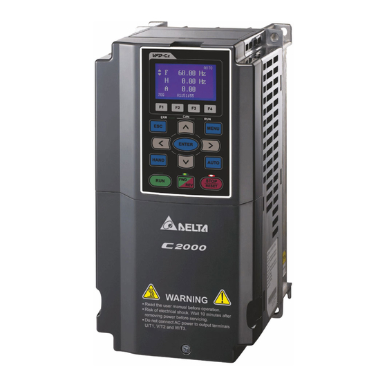
Delta C2000 Series Manuals
Manuals and User Guides for Delta C2000 Series. We have
8
Delta C2000 Series manuals available for free PDF download: User Manual, Manual, Product Application
Delta C2000 Series User Manual (631 pages)
Classical Field Oriented Control AC Motor Drive
Brand:
Delta
| Category:
Controller
| Size: 29.57 MB
Table of Contents
Safety Rules
2
Table of Contents
3
Receiving and Inspection
6
Nameplate Information
6
Chapter 1 Introduction
6
Serial Number
6
Model Name
7
Serial Number
7
RFI Jumper
8
Frame A~C
8
Frame D0~H
9
Main Power Isolated from Earth
9
Dimensions
10
Frame a
10
Frame B
11
Frame C
12
Frame D0:
13
Frame D
15
Frame E
17
Frame F
19
Frame G
21
Frame H
23
Digital Keypad
26
Kpc-Cc01
26
Minimum Mounting Clearance and Installation
27
Single Drive Installation (Frame A-H)
27
Side-By-Side Installation (Frame A-C)
27
Multiple Drives, Side-By-Side Installation(Frame A, B, C, G, H)
27
Chapter 2 Installation
27
Minimum Mounting Clearance
28
Multiple Drives Side-By-Side Installation and in Rows (Frame A, B, C )
28
Multiple Drives, Side-By-Side Installation (Frame D0, D, E, F)
28
Air Flow Rate for Cooling
29
Power Dissipation of AC Motor Drive
29
Derating Curve Diagram of Normal Duty
31
Derating Curve Diagram of Heavy Duty
32
Chapter 3 Unpacking
33
The Lifting Hook
45
Weight
47
Chapter 4 Wiring
49
Wiring Diagram for Frame A~C
50
Wiring Diagram for Frame D and Frames above
51
Sink Mode with External Power
52
Sink Mode with Internal Power (+24VDC )
52
Source Mode with External Power
52
Source Mode with Internal Power (+24VD C)
52
Function of DC Link
53
Operation Instruction
53
For Frame A~C
54
For Frame D and above D
54
Main Circuit Diagram
54
Chapter 5 Main Circuit Terminals
54
Main Power Terminals
55
Output Terminals for Main Circuit
56
Terminals for Connecting DC Reactor, External Brake Resistor, Externalbrake Resistor and DC Circuit
56
Main Circuit Terminals
58
Remove the Cover for Wiring. Frame A~H
67
Factory Setting (NPN Mode)
69
Removable Terminal Block
69
Specifications of Control Terminal
69
Terminal Function
69
Analog Input Terminals (AVI, ACI, AUI, ACM)
71
Digital Inputs (FWD, REV, MI1~MI8, COM)
71
Transistor Outputs (MO1, MO2, MCM)
71
Remove the Terminal Block
72
All Brake Resistors and Brake Units Used in AC Motor Drives
73
Chapter 7 Optional Accessories
73
Definition for Brake Usage ED%
74
Thermal Relay
75
Non-Fuse Circuit Breaker
76
Fuse Specification Chart
77
230V, 50/60Hz, 3-Phase
78
460V, 50/60Hz, 3-Phase
78
Line & Load AC Reactors (Chokes)
78
600V Insulated Cable Wire
79
Zero Phase Reactors (Chokes)
79
230V DC Choke
80
460V DC Choke
80
DC Reactors (Chokes)
80
EMI Filter
81
EMI Filter Installation
82
Cable Length Suggestion for Drive in Full Load
83
Effect of Surge Voltages for Motor and Suggestion
83
The Length of Motor Cable
83
Digital Keypad
84
Function
84
KPC-CE01 View
84
LED Display and Status Indicator
84
Dimension
85
RJ45 Extension Lead for Digital Keypad
85
Panel Mounting (MKC-KPPK)
86
Appearance
88
Conduit Box Kit
88
Conduit Box Installation
89
Frames of the Fan Kit
94
Fan Removal
98
Fan Model (MKC-FFKM/MKC-FFKB)
102
Fan Model (MKC-GFKM)
103
Fan Model (MKC-HFKM)
104
Applicable Models, Frame A~F
105
Cutout Dimension
105
Flange Mounting Kit
105
Mkc-Afm1/Mkc-Afm
105
MKC-AFM1 Installation
106
MKC-AFM Installation
107
Mkc-Bfm
108
MKC-BFM Installation
109
Mkc-Cfm
110
MKC-CFM Installation
111
Frame D0 & D & E
113
Application & Dimension
117
Specifications
117
USB/RS-485 Communication Interface IFD6530
117
Preparations before Driver Installation
118
Driver Installation
119
LED Display
120
Option Cards
121
Removed Key Cover
121
Screws Speciation for Option Card Terminals
123
8-3 Emc-D42A
124
8-4 Emc-D611A
124
8-5 Emc-R6Aa
124
8-6 Emc-Bps01
125
8-7 Emc-Pg01L
126
PG2 Wiring Diagram
126
8-8 Emc-Pg01O
128
PG1 Wiring Diagram
128
Terminal Descriptions
128
8-9 Emc-Pg01U
130
8-10 Emc-Pg01R
132
8-11 CMC-Mod01
134
Electrical Specification
134
Network Interface
134
Product File
134
Environment
135
Install CMC-MOD01 to VFD-C2000
135
Communication Parameters for VFD-C2000 Connected to Ethernet
136
Disconnecting CMC- MOD01 from VFD-C2000
136
Basic Registers
137
LED Indicator & Troubleshooting
137
8-12 CMC-Pd01
139
Communication
139
Product Profile
139
PROFIBUS DP Connector
139
Net Led
140
Power Led
140
8-13 CMC-Dn01
141
AC Motor Drive Connection Port
141
Devicenet Connector
141
Functions
141
Ms Led
143
Ns Led
143
8-14 CMC-Eip01
144
Connecting CMC-EIP01 to Network
145
Connecting CMC-EIP01 to VFD-C2000
145
RJ-45 PIN Definition
145
Disconnecting CMC- EIP01 from VFD-C2000
147
Canopen Communication Cable
149
Canopen Dimension
149
Emc-Cop01
149
9-1 230V Series
150
Specification
150
9-2 460V Series
152
General Specifications
153
Environment for Operation, Storage and Transportation
154
Derating of Ambient Tempeture and Altitude
155
Specification for Operation Temperature and Protection Level
155
C Type Derating for Altitude
156
Descriptions of Digital Keypad
157
Descriptions of Keypad Functions
157
Descriptions of LED Functions
158
Function of Digital Keypad KPC-CC01
160
Detail Parameter
161
Display Icon
161
Display Item
161
Copy Parameter
162
Keypad Locked
162
Copy PLC
163
Fault Record
163
Quick/Simple Setting
164
Display Setup
168
Language Setup
168
Startup Page Setting
168
Time Setting
168
Main Page
169
PC Link
169
Optional Accessory: RJ45 Extension Lead for Digital Keypad
170
Other Display
170
Edit Startup Page
171
Tpeditor Installation Instruction
171
Tpeditor: Setup & Basic Functions
171
Geometric Bitmap
172
Static Bitmap
172
Static Text
172
Download
173
Edit Main Page
174
Numeric/Ascii Display
174
Scale Setting
174
Bar Graph Setting
175
Button
175
Clock Display Setting
176
Numeric Input Setting
176
Unit Measurement
176
Download TP Page
177
Digital Keypad KPC-CC01 Fault Codes and Descriptions
178
Fault Descriptoin of File Copy and Setting Errors
179
Drive Parameters
181
Summary of Parameter Settings
181
Basic Parameters
187
Digital Input/Output Parameters
189
Analog Input/Output Parameters
193
Multi-Step Speed Parameters
196
Motor Parameters
198
Protection Parameters
200
Special Parameters
205
High-Function PID Parameters
207
Communication Parameters
208
Speed Feedback Control Parameters
212
Advanced Parameters
214
Description of Parameter Settings
216
Settings Read Only
216
Content of Multi-Function Display
217
Parameter Reset
217
Start-Up Display Selection
217
Coefficient Gain in Actual Output Frequency
220
Parameter Protection Password Input
220
Parameter Protection Password Setting
220
Software Version
220
Control of Speed Mode
221
Password Decode Flow Chart
221
Reserved
221
When Setting Pr.00-11 to 0, the V/F Control Diagram Is Shown as Follows
222
When Setting Pr.00-11 to 1, the V/F Control + Encoder Diagram Is Shown as Follows
222
When Setting Pr.00-11 to 2, the Sensorless Vector Control Diagram Is Shown as Follows
223
When Setting Pr.00-11 to 3, the FOCPG Control Diagram Is Shown as Follows
223
When Setting Pr.00-11 to 4, the FOCPG Control Diagram Is Shown as Follows
224
When Setting Pr.00-11 to 5, FOC Sensorless Control Diagram Is Shown as Follows
224
Control of Torque Mode
225
Point to Point Position Control
225
When Setting Pr.00-11 to 6, PM FOC Sensorless Control Diagram Is Shown as Follows
225
TQCPG Control Diagram Is Shown in the Following
226
Carrier Frequency
227
Load Selection
227
TQC Sensorless Control Diagram Is Shown in the Following
227
PLC Command Mask
228
Source of the Master Frequency Command(Auto)
228
Source of the Operation Command (AUTO)
229
Stop Method
229
Control of Motor Direction
230
Memory of Frequency Command
230
User Defined Characteristics
230
Max. User Defined Value
231
User Defined Value
231
LOCAL/REMOTE Selection
232
Source of the Master Frequency Command(Hand)
232
Digital Keypad STOP Function
233
Homing Mode
233
Source of the Operation Command (HAND)
233
Display Filter Time (Current)
236
Display Filter Time (Keypad)
236
Homing by Frequency 1 & 2
236
Software Version (Date)
236
Maximum Output Frequency
237
MID-Point Voltage/Frequency 1 of Motor 1/2
237
Output Frequency of Motor 1 & 2(Base Frequency and Motor Rated Frequency)
237
Output Voltage of Motor 1 & 2(Base Frequency and Motor Rated Frequency)
237
MID-Point Frequency/Voltage 2 of Motor 1/2
238
Min. Output Voltage/Frequency of Motor 1/2
238
Common Settings of V/F Curve
239
Output Frequency Upper Limit
240
Start-Up Frequency
240
Output Frequency Lower Limit
241
Accel. Time 1-4
242
Decel. Time 1-4
242
JOG Acceleration Time
242
JOG Deceleration Time
242
1St/4Th Accel./Decel. Frequency
243
JOG Frequency
243
S-Curve Acceleration Begin Time 1
243
S-Curve Acceleration/Deceleration Arrival Time 2
244
S-Curve Deceleration Begin Time 1
244
Skip Frequency 1-3 (Lower Limit)
244
Skip Frequency 1-3 (Upper Limit)
244
V/F Curve Selection
245
Zero-Speed Mode
245
Optimal Acceleration/Deceleration Setting
246
Time for Canopen Quick Stop
247
Time Unit for Acceleration/Deceleration and S Curve
247
2-Wire/3-Wire Operation Control
248
Digital Input/Output Parameter
248
Input Terminal of I/O Extension Card (MI10-MI12)
248
Multi-Function Input Command 1-8 (MI1-MI8)
248
Input Terminal of I/O Extension Card (MI13-MI15)
249
Constant Speed. the Accel. /Decel. Speed of the UP/DOWN Key
257
Digital Input Response Time
257
UP/DOWN Key Mode
257
Digital Input Operation Setting
258
Multi-Function Output 1,2 (Relay 1,2)
258
Multi-Function Output 3,4 (MO1, MO2)
258
Output Terminal of I/O Extension Card (MO10-MO20) or (RA10-RA15)
258
Multi-Function Output Setting
264
Desired Frequency Attained 1, 2
265
Digital Output Gain(Dfm)
265
Preliminary Counting Value Attained (Not Return to 0)
265
Terminal Counting Value Attained (Return to 0)
265
Brake Delay Time
266
The Width of the Desired Frequency Attained 2
266
Output Current Level Setting for Multi-Function Output Terminals
267
External Operation Control Selection after Reset and Activate
268
Output Boundary for Multi-Function Output Terminals
268
Switch the Delay Time of Max. Output Frequency
268
Zero-Speed Level of Motor
268
Display the Status of Multi-Function Input Terminal
269
Display External Output Terminal Occupied by PLC
270
Status of Multi-Function Output Terminal
270
Display Multi-Function Output Terminal Occupied by PLC
271
Display the Frequency Command Executed by External Terminal
272
Multi-Function Output Terminal: Function 42: Brake Frequency Checking Point
272
Analog Input Selection (AVI & ACI & AUI)
273
Analog Input Bias (AVI & ACI)
274
Analog Voltage Input Bias (AUI)
274
Positive/Negative Bias Mode (AVI & ACI & AUI)
274
Analog Frequency Command for Reverse Run
291
Analog Input Filter Time (AVI & ACI & AUI)
291
Analog Input Gain (AVI & ACI)
291
Analog Negative/Positive Input Gain (AUI)
291
Addition Function of the Analog Input
292
Multi-Function Output 1, 2 (AFM1, AFM2)
292
Treatment to 4-20Ma Analog Input Signal Loss
292
Analog Output 1, 2 When in REV Direction (AFM1, AFM2)
293
Gain of Analog Output 1, 2 (AFM1, AFM2)
293
AFM2 Output Bias
294
AVI & ACI Selection
294
AFM1, AFM2 DC Output Setting Level
295
AFM1, AFM2 Filter Output Time
295
AFM2 0-20Ma Output Selection
295
Status of PLC Output Terminal
295
Analog Input Curve Selection
296
AVI Low/MID/High Point
296
AVI Proportional Low/MID/High Point
296
ACI Low/MID/High Point
298
ACI Proportional Low/MID/High Point
298
Positive AUI Voltage Low Point
298
Positive AUI Voltage Proportional Low Point
298
Negative AUI Voltage Low/MID/High Point
299
Negative AUI Voltage Proportional Low/MID/High Point
299
Positive AUI Voltage MID/High Point
299
Positive AUI Voltage Proportional MID/High Point
299
1-15 Step Speed Frequency
301
Position Command 1-15 (Pulse)
302
Position Command 1-15 (Revolution)
303
PLC Buffer 1-10
304
Induction Motor
305
Motor Auto Tuning
305
To Begin AUTO-Tuning in Rolling Test
305
Permanent Magnet Motor (PM)
306
Set up Sensorless FOC Mode
306
To Begin AUTO-Tuning for PM Motor in Rolling Test
306
Auto-Tuning Process for Measuring PG Offset Angle of PM Motor
307
Full-Load Current of Induction Motor 1(A)
307
No-Load Current of Induction Motor 1 (A)
308
Pole Number of Induction Motor 1
308
Rated Power of Induction Motor 1(Kw)
308
Rated Speed of Induction Motor 1 (Rpm)
308
No-Load Current of Induction Motor 2 (A)
309
Pole Number of Induction Motor 2
309
Rated Power of Induction Motor 2 (Kw)
309
Rated Speed of Induction Motor 2 (Rpm)
309
Delay Time for Y-Connection/△-Connection Switch of Induction Motor
310
Frequency for Y-Connection/△-Connection Switch of Induction Motor
310
Y-Connection/△-Connection Switch of Induction Motor IM
310
Accumulative Watt Per Second of Motor in Low/High Word (W-Sec)
311
Accumulative Watt-Hour of Motor (W-Hour)
311
Accumulative Watt-Hour of Motor in Low/High Word (KW-Hour)
311
Accumulative Motor Operation Time (Min, Day)
312
Full-Load Current of Permanent Magnet Motor
312
Induction Motor (IM) and Permanent Magnet Motor Selection
312
Inertia of Permanent Magnet Motor
312
Ke Parameter of PM Motor
313
Permanent Magnet Motor Ld, Lq
313
PG Offset Angle of PM Motor
313
Stator Resistance of PM Motor
313
Low Voltage Level
314
Over-Voltage Stall Prevention
314
Selection for Over-Voltage Stall Prevention
315
Over-Current Stall Prevention During Acceleration
316
Over-Current Stall Prevention During Operation
316
Accel./Decel. Time Selection of Stall Prevention at Constant Speed
317
Over-Torque Detection Selection (OT1, OT2)
317
Current Limit
318
Over-Torque Detection Level (OT1)
318
Over-Torque Detection Level (OT2)
318
Electronic Thermal Characteristic for Motor 1, 2
319
Electronic Thermal Relay Selection (Motor 1, 2)
319
Heat Sink Over-Heat (OH) Warning
319
Fifth/Sixth most Recent Fault Record
320
Second/Third most Recent Fault Record
320
Stall Prevention Limit Level (Flux Weakening Area Current Stall Prevention Level)
320
Third/Fourth most Recent Fault Record
320
Fault Output Option 1-4
323
PTC (Positive Temperature Coefficient) Detection Selection
325
PTC Level
325
DC Voltage at Malfunction
326
Frequency Command for Malfunction
326
IGBT Temperature at Malfunction
326
Output Frequency/Voltage/Current at Malfunction
326
Deceleration Time of Output Phase Loss
327
Drive Status at Malfunction
327
Status of Multi-Function Input/Output Terminal at Malfunction
327
Torque Command at Malfunction
327
Current Detection Level of Output Phase Loss
328
Derating Protection
328
Output Phase Loss Detection Function Executing Time before Run
328
Derating Curve Diagram in the Normal Duty
330
PT100 Detection Level 1, 2
333
PT100 Level 1 Frequency Protection
333
Set up Process
334
Software Detection GFF Current Level
334
Software Detection GFF Filter Time
334
Disable Level of Deb
335
Fault Record 1-4 (Day)
335
Fault Record 1-4 (Min)
335
Low Current Detection Time
336
Low Current Setting Level
336
Treatment for Low Current
336
DC Brake Current Level
338
DC Brake Time at Start-Up/Stop
338
Software Brake Level
338
Restart after Momentary Power Loss
339
Start-Point for DC Brake
339
Voltage Incrasing Gain
339
Base Block Time
340
Maximum Power Loss Duration
340
Current Limit for Speed Search
341
Treatment after Fault
341
Auto Restart Time after Fault
342
Deb Return Time
342
Decel. Time at Momentary Power Loss (Deb Function)
342
Speed Search During Start-Up
342
Dwell Frequency at Accel./Decel.
344
Dwell Time at Accel./Decel.
344
Fan Cooling Control
344
Emergency Stop (EF) & Force Stop
345
FOCPG (IM) Control Mode
345
VF, VFPG, SVC Control Mode
345
Auto Voltage Regulation(AVR) Function
346
Energy-Saving Gain
346
Filter Time of Slip Compensation (V/F and SVC Control Mode)
347
Filter Time of Torque Command (V/F and SVC Control Mode)
347
Slip Compensation Gain (V/F and SVC Control Mode)
347
Torque Compensation Gain (V/F and SVC Control Mode)
347
Detection Time of Slip Deviation
348
Motor Hunting Gain
348
Over Slip Treatment
348
Slip Deviation Level
348
Recovery Time to Pr.07-11
349
Common Applications for PID Control
350
Input Terminal for PID Feedback
350
Concept of PID Control
351
PID Control Loop
351
When PID Control Is Used in a Constant Pressure Pump Feedback Application
351
Integral Time (I)
352
Proportional Gain (P)
352
Derivative Control (D)
353
PID Feedback Value by Communication Protocol
353
PID Output Frequency Limit
353
Upper Limit of Integral Control
353
PID Mode Selection
354
Feedback Signal Detection Time
355
Parallel Connection
355
Serial Connection
355
Feedback Signal Fault Treatment
356
PID Deviation Level
356
Sleep Reference/Time
356
Wake-Up Reference
356
Enable PID to Change the Operation Direction
357
PID Compensation Selection
357
Setting of Sleep Mode Function
357
Wake-Up Integral Limit
357
Frequency Command Calculation of the Internal PID
358
PID Control Bit
358
Wake-Up Delay Time
358
Internal PID Calculation Frequency Command
359
PID Feedback Rate Percentage
359
COM1 Communication Address
360
COM1 Communication Protocol
360
COM1 Transmission Fault Treatment
360
COM1 Transmission Speed
360
Code Description
361
Data Format
361
Communication Data Frame: ASCII Mode
362
Communication Data Frame: RTU Mode
362
Communication Protocol
362
ASCII Mode
363
Function (Function Code) and DATA (Data Characters)
363
RTU Mode
363
Check Sum
365
AC Drive Parameters
367
Address List
367
Command Write Only
367
Status Monitor Read Only
367
Exception Response
369
Advertisement
Delta C2000 Series User Manual (936 pages)
Vector Control Drive
Brand:
Delta
| Category:
DC Drives
| Size: 56.42 MB
Table of Contents
Table of Contents
6
Chapter 1 Introduction
10
Nameplate Information
11
Model Name
12
Serial Number
13
Apply after Service by Mobile Device
14
RFI Jumper
15
Dimensions
18
Chapter 2 Installation
36
Mounting Clearance
36
Air Flow and Power Dissipation
36
Chapter 3 Unpacking
42
Unpacking
42
The Lifting Hook
42
Chapter 4 Wiring
72
System Wiring Diagram
72
Wiring
75
Chapter 5 Main Circuit Terminals
80
Main Circuit Diagram
83
Specifications of Main Circuit Terminals
86
Remove the Cover for Wiring
98
Specifications of Control Terminal
98
Remove the Terminal Block
98
Chapter 7 Optional Accessories
108
All Brake Resistors and Brake Units Used in AC Motor Drives
109
Non-Fuse Circuit Breaker
114
Fuse Specification Chart
115
AC / DC Reactor
117
Zero Phase Reactor
153
EMC Filter
157
Panel Mounting
177
Digital Keypad
177
Conduit Box Kit
179
Fan Kit
196
Flange Mounting Kit
212
USB/RS-485 Communication Interface IFD6530
229
Chapter 8 Option Cards
234
Option Card Installation
235
EMC-D42A -- Extension Card for 4-Point Digital Input / 2-Point Digital Input
247
Emc-D611A
247
AC Input Voltage)
247
EMC-R6AA -- Relay Output Extension Card (6-Point N.O. Output Contact)
247
EMC-A22A -- Extension Card for 2-Point Analog Input/ 2-Point Analog Output
248
EMC-BPS01 -- +24V Power Card
248
EMC-PG01R -- PG Card (Resolver)
257
CMC-MOD01 -- Communication Card, Modbus TCP
259
CMC-PD01 -- Communication Card, PROFIBUS DP
262
CMC-DN01 -- Communication Card, Devicenet
264
CMC-EIP01 -- Communication Card, Ethernet/Ip
267
CMC-EC01 -- Communication Card, Ethercat
271
CMC-PN01 -- Communication Card, PROFINET
274
EMC-COP01 -- Communication Card, Canopen
278
Delta Standard Fieldbus Cables
279
Chapter 9 Specification
280
Environment for Operation, Storage and Transportation
280
Specification for Operation Temperature and Protection Level
280
Derating Curve of Ambient Temperature
280
V Series
281
Efficiency Curve
296
Chapter 10 Digital Keypad
298
Descriptions of Digital Keypad
299
Function of Digital Keypad KPC-CC01
302
Tpeditor Installation Instruction
323
Delta C2000 Series User Manual (540 pages)
Classical field oriented. Control AC motor drive
Brand:
Delta
| Category:
DC Drives
| Size: 25.65 MB
Table of Contents
Table of Contents
3
Group
4
Chapter 1 Introduction
6
Group
6
Nameplate Information
6
Receiving and Inspection
6
Model Name
7
Serial Number
7
RFI Jumper
8
Dimensions
10
Chapter 2 Installation
25
Minimum Mounting Clearance and Installation
25
Minimum Mounting Clearance
26
Derating Curve Diagram of Normal Duty (Pr.00-16=0)
29
Derating Curve Diagram of Heavy Duty (Pr.00-16=1)
30
Chapter 3 Unpacking
31
Chapter 4 Wiring
47
Function of DC Link
51
Chapter 5 Main Circuit Terminals
52
Control Terminals
64
Wiring Precautions
66
Analog Input Terminals (AVI, ACI, AUI, ACM)
68
Digital Inputs (FWD, REV, MI1~MI8, COM)
68
Remove the Terminal Block
68
Transistor Outputs (MO1, MO2, MCM)
68
Chapter 7 Optional Accessories
69
All Brake Resistors and Brake Units Used in AC Motor Drives
70
Non-Fuse Circuit Breaker
73
Fuse Specification Chart
74
AC Reactor
75
Applications for AC Reactor
76
Zero Phase Reactors
77
DC Reactor
78
EMI Filter
79
Choose Suitable Motor Cable and Precautions
80
EMI Filter Installation
80
General Precaution
80
Group
80
The Length of Motor Cable
81
Digital Keypad
82
Kpc-Ce01
82
RJ45 Extension Lead for Digital Keypad
83
Panel Mounting (MKC-KPPK)
84
Conduit Box Kit
86
Conduit Box Installation
87
Fan Kit
92
Frames of the Fan Kit
92
Fan Removal
95
Flange Mounting Kit
100
Frame D&E
108
USB/RS-485 Communication Interface IFD6530
112
Preparations before Driver Installation
113
Driver Installation
114
LED Display
115
Chapter 8 Option Cards
116
Removed Key Cover
116
Screws Speciation for Option Card Terminals
118
Wiring Diagram
122
Terminal Descriptions
123
PG2 Wiring Diagram
124
Emc-Pg01U
125
CMC-Mod01
129
Communication Parameters for VFD-C2000 Connected to Ethernet
130
Install CMC-MOD01 to VFD-C2000
130
Basic Registers
131
Disconnecting CMC-MOD01 from VFD-C2000
131
LED Indicator & Troubleshooting
132
CMC-Pd01
133
CMC-Dn01
135
Group
135
CMC-Eip01
138
Connecting CMC-EIP01 to VFD-C2000
139
RJ-45 PIN Definition
139
Disconnecting CMC- EIP01 from VFD-C2000
141
Emc-Cop01
143
Chapter 9 Specification
144
Environment for Operation, Storage and Transportation
148
Specification for Operation Temperature and Protection Level
149
Chapter 10 Digital Keypad
150
Descriptions of Digital Keypad
150
Descriptions of Keypad Functions
150
Descriptions of LED Functions
151
Function of Digital Keypad KPC-CC01
153
Detail Parameter
154
Display Icon
154
Display Item
154
Copy Parameter
155
Keypad Locked
155
PLC Function
155
Copy PLC
156
Fault Record
156
Quick/Simple Setting
157
Display Setup
161
Language Setup
161
Startup Page Setting
161
Time Setting
161
Main Page
162
PC Link
162
Optional Accessory: RJ45 Extension Lead for Digital Keypad
163
Other Display
163
Edit Startup Page
164
Tpeditor Installation Instruction
164
Tpeditor: Setup & Basic Functions
164
Edit Main Page
167
Digital Keypad KPC-CC01 Fault Codes and Descriptions
171
Fault Descriptoin of File Copy and Setting Errors
172
Drive Parameters
174
Summary of Parameter Settings
174
Digital Input/Output Parameters
181
Analog Input/Output Parameters
185
Multi-Step Speed Parameters
188
Motor Parameters
190
Protection Parameters
192
Special Parameters
197
High-Function PID Parameters
199
Communication Parameters
200
Speed Feedback Control Parameters
204
Advanced Parameters
206
Description of Parameter Settings
208
Content of Multi-Function Display
209
Parameter Reset
209
Start-Up Display Selection
209
Coefficient Gain in Actual Output Frequency
211
Parameter Protection Password Input
212
Parameter Protection Password Setting
212
Control Mode
213
Control of Speed Mode
213
Control of Torque Mode
217
Carrier Frequency
218
Load Selection
218
PLC Command Mask
219
Source of the Master Frequency Command(Auto)
219
Source of the Operation Command (AUTO)
220
Stop Method
220
Control of Motor Direction
221
Max. User Defined Value
221
Memory of Frequency Command
221
User Defined Characteristics
221
LOCAL/REMOTE Selection
222
User Defined Value
222
Digital Keypad STOP Function
223
Source of the Master Frequency Command(Hand)
223
Source of the Operation Command (HAND)
223
Homing Mode
224
Display Filter Time (Current)
226
Display Filter Time (Keypad)
226
Reserved
226
Software Version (Date)
226
Basic Parameters
227
Group
227
Maximum Output Frequency
227
MID-Point Frequency
227
Common Settings of V/F Curve
229
Output Frequency Lower Limit
230
Start-Up Frequency
230
JOG Acceleration Time
232
JOG Deceleration Time
232
1St/4Th Accel./Decel. Frequency
233
JOG Frequency
233
S-Curve Acceleration/Deceleration
233
Zero-Speed Mode
234
V/F Curve Selection
235
Optimal Acceleration/Deceleration Setting
236
Time for Canopen Quick Stop
237
Time Unit for Acceleration/Deceleration and S Curve
237
2-Wire/3-Wire Operation Control
238
Digital Input/Output Parameter
238
Constant Speed. the Accel. /Decel. Speed of the UP/DOWN Key
246
UP/DOWN Key Mode
246
Digital Input Operation Direction
247
Digital Input Response Time
247
Multi-Function Output Direction
253
Terminal Counting Value Attained (Return to 0)
253
Digital Output Gain(Dfm)
254
Preliminary Counting Value Attained (Not Return to 0)
254
Brake Delay Time
255
External Operation Control Selection after Reset and Activate
256
Output Boundary for Multi-Function Output Terminals
256
Output Current Level Setting for Multi-Function Output Terminals
256
Switch the Delay Time of Max. Output Frequency
257
Zero-Speed Level of Motor
257
Display the Status of Multi-Function Input Terminal
258
Status of Multi-Function Output Terminal
258
Display External Output Terminal Occupied by PLC
259
Display Analog Input Terminal Occupied by PLC
260
Display the Frequency Command Executed by External Terminal
260
Analog Input/Output Parameter
262
Analog Input Bias (ACI)
263
Analog Voltage Input Bias (AUI)
263
Positive/Negative Bias Mode (AUI)
263
Analog Frequency Command for Reverse Run
279
Addition Function of the Analog Input
280
Treatment to 4-20Ma Analog Input Signal Loss
280
AFM2 Output Bias
282
AVI Selection
282
ACI Selection
283
Status of PLC Output Terminal
283
Analog Input Curve Selection
284
AVI Low Point
284
ACI Proportional High Point
285
Positive AUI Voltage Proportional High Point
286
Motor Auto Tuning
291
Permanent Magnet Motor (PM)
292
Full-Load Current of Induction Motor 1(A)
293
Pole Number of Induction Motor 1
294
Rated Power of Induction Motor 1(Kw)
294
Rated Speed of Induction Motor 1 (Rpm)
294
Delay Time for Y-Connection/△-Connection Switch of Induction Motor
296
Low Voltage Level
300
Over-Voltage Stall Prevention
300
Over-Current Stall Prevention During Acceleration
301
Selectionfor Over-Voltage Stall Prevention
301
Over-Current Stall Prevention During Operation
302
Accel./Decel. Time Selection of Stall Prevention at Constant Speed
303
Over-Torque Detection Selection (OT1)
303
Over-Torque Detection Selection (OT2)
303
Current Limit
304
Heat Sink Over-Heat (OH) Warning
305
Stall Prevention Limit Level
306
Frequency Command for Malfunction
311
Output Frequency at Malfunction
311
PTC (Positive Temperature Coefficient) Detection Selection
311
PTC Level
311
DC Voltage at Malfunction
312
IGBT Temperature at Malfunction
312
Output Current at Malfunction
312
Output Voltage at Malfunction
312
Derating Protection
314
Ripple of Input Phase Loss
314
PT100 Level 1 Frequency Protection
318
DC Brake Current Level
322
DC Brake Time at Start-Up
322
DC Brake Time at Stop
322
Software Brake Level
322
Restart after Momentary Power Loss
323
Voltage Incrasing Gain
323
Base Block Time
324
Maximum Power Loss Duration
324
Current Limit for Speed Search
325
Treatment to Reboots after Fault
325
Auto Restart after Fault
326
Deb Return Time
326
Decel. Time at Momentary Power Loss (Deb Function)
326
Speed Search During Start-Up
326
Emergency Stop (EF) & Force Stop
328
Fan Cooling Control
328
Auto Energy-Saving Operation
329
Auto Voltage Regulation(AVR) Function
329
Energy-Saving Gain
329
Filter Time of Slip Compensation (V/F and SVC Control Mode)
330
Filter Time of Torque Command (V/F and SVC Control Mode)
330
Torque Compensation Gain (V/F and SVC Control Mode)
330
Slip Compensation Gain (V/F and SVC Control Mode)
331
Input Terminal for PID Feedback
333
Derivative Control (D)
335
Integral Time (I)
335
Proportional Gain (P)
335
PID Mode Selection
336
PID Output Frequency Limit
336
Upper Limit of Integral Control
336
Feedback Signal Detection Time
338
Feedback Signal Fault Treatment
338
Sleep Time
338
Filter Time for PID Feedback
339
PID Compensation Selection
339
COM1 Communication Address
340
COM1 Communication Protocol
340
COM1 Transmission Fault Treatment
340
COM1 Transmission Speed
340
Address List
347
Exception Response
349
Main Frequency of the Communication
350
Response Delay Time
350
Communication Decoding Method
351
Internal Communication Protocol
351
Encoder Input Type Setting
357
Encoder Pulse
357
Encoder Type Selection
357
PID Control
357
Output Setting for Frequency Division (Denominator)
358
Detection Time of Encoder Feedback Fault
359
Encoder Stall Level
359
Treatment for Encoder Feedback Fault
359
Treatment for Encoder Stall
359
Pulse Input Type Setting (PG Card: PG2)
360
Treatment for Encoder Stall and Slip Error
360
Positioning for Encoder Position
361
Range for Encoder Position Attained
361
FOC Bandwidth of Speed Observer
362
FOC Low-Pass Filter Time Constant
362
FOC Minimum Stator Frequency
362
FOC&TQC Function Control
362
PM Sensorless Adjustment Procedure
364
System Control
366
Per Unit of System Inertia
367
Low-Pass Filter Time of ASR Output
369
Notch Filter Frequency
369
PDFF Gain Value
369
APR Curve Time
371
Gain Value of APR Feed Forward
371
Speed Response of Flux Weakening Area
371
Max. Torque Command
372
Source of Torque Offset
372
Low Torque Offset
373
Source of Torque Command
373
Torque Command
373
Low-Pass Filter Time of Torque Command
374
Reverse Speed Limit (Torque Mode)
374
Speed Limit Selection
374
Zero Torque Command Mode
374
Command Source of Point-To-Point Position Control
375
Advertisement
Delta C2000 Series User Manual (814 pages)
Vector Control Drive (High Speed Models)
Brand:
Delta
| Category:
DC Drives
| Size: 37.19 MB
Table of Contents
Table of Contents
5
Chapter 1 Introduction
9
Nameplate Information
9
Model Name
9
Serial Number
9
Apply after Service by Mobile Device
9
RFI Jumper
9
Dimensions
16
Chapter 2 Installation
23
Mounting Clearance
23
Flow and Power Dissipation
23
Chapter 3 Unpacking
29
Unpacking
29
The Lifting Hook
29
Chapter 4 Wiring
45
System Wiring Diagram
45
Wiring
45
Chapter 5 Main Circuit Terminals
51
Main Circuit Diagram
54
Main Circuit Terminals
56
Remove the Cover for Wiring
63
Specifications of Control Terminal
63
Remove the Terminal Block
63
Chapter 7 Optional Accessories
73
All Brake Resistors and Brake Units Used in AC Motor Drives
74
Non-Fuse Circuit Breaker
77
Fuse Specification Chart
77
AC/DC Reactors
78
EMC Filter
87
Panel Mounting (MKC-KPPK)
89
Conduit Box Kit
91
Fan Kit
108
Flange Mounting Kit
116
Power Terminal Kit
122
USB/RS-485 Communication Interface IFD6530
124
Chapter 8 Option Cards
129
Option Card Installation
130
Emc-D42A
142
Emc-D611A
142
AC Input Voltage)
142
Emc-R6Aa
142
EMC-A22A -- Extension Card for 2-Point Analog Input / 2-Point Analog Output
143
EMC-BPS01 -- +24V Power Card
143
EMC-PG01R -- PG Card (Resolver)
152
CMC-Mod01
154
CMC-PD01 -- Communication Card, PROFIBUS DP
157
CMC-Dn01
159
CMC-EIP01 -- Communication Card, Ethernet/Ip
162
CMC-EC01 -- Communication Card, Ethercat
166
CMC-Pn01
169
Emc-Cop01
173
Delta Standard Fieldbus Cables
174
Delta C2000 Series User Manual (692 pages)
Classical Field Oriented Control AC Motor Drive
Brand:
Delta
| Category:
Controller
| Size: 54.12 MB
Table of Contents
Table of Contents
3
Chapter 1 Introduction
6
Model Name
7
RFI Jumper
8
Dimensions
12
Chapter 2 Installation
30
Minimum Mounting Clearance
31
Chapter 3 Unpacking
35
The Lifting Hook
47
Chapter 4 Wiring
50
System Wiring Diagram
55
Chapter 5 Main Circuit Terminals
56
Main Circuit Terminals
60
Specifications of Control Terminal
71
Analog Input Terminals (AVI, ACI, AUI, ACM)
73
Remove the Terminal Block
75
Chapter 7 Optional Accessories
76
All Brake Resistors and Brake Units Used in AC Motor Drives
77
Non-Fuse Circuit Breaker
80
Fuse Specification Chart
81
AC/DC Reactor
82
Zero Phase Reactor
85
EMI Filter
87
Digital Keypad
91
Panel Mounting
94
Conduit Box Kit
96
Fan Kit
104
Flange Mounting Kit
117
USB/RS-485 Communication Interface IFD6530
130
Chapter 8 Option Cards
134
Removed Key Cover
135
Screws Specification for Option Card Terminals
138
Emc-D42A
143
Emc-Bps01
144
Emc-Pg01R
153
CMC-Mod01
155
CMC-Pd01
159
CMC-Dn01
161
CMC-Eip01
164
Chapter 15 Canopen Overview
169
Chapter 9 Specification
170
V Series
171
Environment for Operation, Storage and Transportation
173
Specification for Operation Temperature and Protection Level
174
Chapter 10 Digital Keypad
176
Descriptions of Digital Keypad
177
Function of Digital Keypad KPC-CC01
180
Tpeditor Installation Instruction
198
Chapter 11 Summarpy of Parameters
252
Chapter 12 Description of Parameter Settings
252
Chapter 13 Warning Codes
441
Chapter 14 Fault Codes and Descriptions
449
Delta C2000 Series User Manual (653 pages)
Vector control drive
Brand:
Delta
| Category:
DC Drives
| Size: 41.03 MB
Table of Contents
Table of Contents
3
Receiving and Inspection
6
Nameplate Information
6
Model Name
7
Serial Number
7
RFI Jumper
9
Unpacking
34
The Lifting Hook
34
Wiring
50
System Wiring Diagram
50
Main Circuit Diagram
58
Main Circuit Terminals
58
Specifications of Control Terminal
72
Remove the Terminal Block
72
All Brake Resistors and Brake Units Used in AC Motor Drives
82
Non-Fuse Circuit Breaker
82
Fuse Specification Chart
82
AC/DC Reactor
82
Zero Phase Reactor
82
EMI Filter
82
Digital Keypad
82
Panel Mounting
82
Conduit Box Kit
82
Fan Kit
82
Removed Key Cover
140
Emc-D42A
143
Emc-Bps01
144
Emc-Pg01R
145
CMC-Mod01
146
CMC-Pd01
166
CMC-Dn01
169
CMC-Eip01
172
Environment for Operation, Storage and Transportation
178
Descriptions of Digital Keypad
186
Delta C2000 Series Manual (22 pages)
Brand:
Delta
| Category:
Media Converter
| Size: 1.92 MB
Delta C2000 Series Product Application (5 pages)
Brand:
Delta
| Category:
Engine
| Size: 1.06 MB
Advertisement
Related Products
Delta C2000-HS Series
Delta C200 Series
Delta C2000 Plus Series
Delta CTA4000A Series
Delta CMM-EIP03
Delta ShopMaster CL144
Delta CMM-DN02
Delta DeviceNet CME-DN01
Delta Prelude C41901-WH
Delta Vivotek CC9160-H
Delta Categories
Plumbing Product
Kitchen & Bath Fixtures
Bathroom Fixtures
Saw
Power Supply
More Delta Manuals
Login
Sign In
OR
Sign in with Facebook
Sign in with Google
Upload manual
Upload from disk
Upload from URL