evertz 7700 Series Manuals
Manuals and User Guides for evertz 7700 Series. We have 142 evertz 7700 Series manuals available for free PDF download: Manual, Quick Start Manual

evertz 7700 Series Manual (164 pages)
HD/SD Logo Inserter & Media Keyer
Brand: evertz
|
Category: Network Hardware
|
Size: 2 MB
Table of Contents
Advertisement

evertz 7700 Series Manual (94 pages)
Brand: evertz
|
Category: Computer Hardware
|
Size: 1 MB
Table of Contents

evertz 7700 Series Manual (70 pages)
Quad Data Embedder
Brand: evertz
|
Category: Network Hardware
|
Size: 1 MB
Table of Contents
Advertisement

evertz 7700 Series Manual (62 pages)
Composite Encoder with Monitoring
Brand: evertz
|
Category: Media Converter
|
Size: 0 MB
Table of Contents

evertz 7700 Series Manual (62 pages)
Component D to A
Brand: evertz
|
Category: Network Hardware
|
Size: 2 MB
Table of Contents

evertz 7700 Series Manual (65 pages)
MultiViewer Monitoring
Brand: evertz
|
Category: Network Hardware
|
Size: 2 MB
Table of Contents

evertz 7700 Series Manual (66 pages)
HD Format Up/Down/Cross Converter
Brand: evertz
|
Category: Media Converter
|
Size: 0 MB
Table of Contents
evertz 7700 Series Manual (62 pages)
Frame Synchronizers
Brand: evertz
|
Category: I/O Systems
|
Size: 0 MB
Table of Contents

evertz 7700 Series Manual (62 pages)
SD Aspect Ratio Converter
Brand: evertz
|
Category: Media Converter
|
Size: 1 MB
Table of Contents

evertz 7700 Series Manual (48 pages)
Video Composite Encoder and Audio DAC with SoftSwitch
Brand: evertz
|
Category: Media Converter
|
Size: 0 MB
Table of Contents


evertz 7700 Series Manual (44 pages)
Cable TV Fiber Transmitter / Receiver
Brand: evertz
|
Category: Transmitter
|
Size: 0 MB
Table of Contents

evertz 7700 Series Manual (49 pages)
High Quality Down Converter
Brand: evertz
|
Category: Media Converter
|
Size: 0 MB
Table of Contents

evertz 7700 Series Manual (58 pages)
Modular Router
Brand: evertz
|
Category: Computer Hardware
|
Size: 2 MB
Table of Contents

evertz 7700 Series Manual (46 pages)
HD Broadcast Quality Down Converter
Brand: evertz
|
Category: Media Converter
|
Size: 0 MB
Table of Contents


evertz 7700 Series Manual (50 pages)
Brand: evertz
|
Category: Network Hardware
|
Size: 1 MB
Table of Contents

evertz 7700 Series Manual (44 pages)
HD Broadcast Quality Down Converter
Brand: evertz
|
Category: Media Converter
|
Size: 0 MB
Table of Contents
evertz 7700 Series Manual (40 pages)
L-Band Fiber Receivers/Transmitters
Brand: evertz
|
Category: Transmitter
|
Size: 0 MB
Table of Contents

evertz 7700 Series Manual (39 pages)
Closed Caption & XDS Monitoring Display
Brand: evertz
|
Category: Network Hardware
|
Size: 1 MB
Table of Contents

evertz 7700 Series Manual (40 pages)
HD/SD Noise Reducer
Brand: evertz
|
Category: Computer Hardware
|
Size: 0 MB
Table of Contents

evertz 7700 Series Manual (38 pages)
HD UpConverter
Brand: evertz
|
Category: Media Converter
|
Size: 0 MB
Table of Contents

evertz 7700 Series Manual (48 pages)
MultiFrame Nielsen Universal Reader
Brand: evertz
|
Category: Control Unit
|
Size: 1 MB
Table of Contents
evertz 7700 Series Manual (28 pages)
Multiframe Manual IF Fiber Transmitter / Receiver
Table of Contents


evertz 7700 Series Manual (32 pages)
Source Identification Decoder
Brand: evertz
|
Category: Media Converter
|
Size: 0 MB
Table of Contents

evertz 7700 Series Manual (36 pages)
Multi-Signal SDTV Fiber Transciever
Brand: evertz
|
Category: Transceiver
|
Size: 0 MB
Table of Contents

evertz 7700 Series Manual (35 pages)
Composite Encoder with Image Enhancement
Brand: evertz
|
Category: Media Converter
|
Size: 1 MB
Table of Contents

evertz 7700 Series Manual (32 pages)
Unidirectional UMD Protocol Translator
Brand: evertz
|
Category: Electronic dictionary
|
Size: 0 MB
Table of Contents


evertz 7700 Series Manual (34 pages)
Dual Composite Decoder
Brand: evertz
|
Category: Media Converter
|
Size: 0 MB
Table of Contents

evertz 7700 Series Manual (31 pages)
HD Key/Fill Up Converter
Brand: evertz
|
Category: Media Converter
|
Size: 0 MB
Table of Contents

evertz 7700 Series Manual (40 pages)
MPEG2 SD/HD Decoder
Brand: evertz
|
Category: Media Converter
|
Size: 1 MB
Table of Contents

evertz 7700 Series Manual (34 pages)
HD Audio Embedder
Brand: evertz
|
Category: Network Hardware
|
Size: 0 MB
Table of Contents

evertz 7700 Series Manual (32 pages)
Composite Video, Analog Audio and RS232/422 Fiber Receiver
Table of Contents

evertz 7700 Series Manual (30 pages)
Two Channel SDI + Ethernet SONET/SDH Fiber Transmitter
Brand: evertz
|
Category: Transmitter
|
Size: 0 MB
Table of Contents

evertz 7700 Series Manual (28 pages)
Composite Video, Analog Audio and RS232/422 Fiber Transmitter
Brand: evertz
|
Category: Transmitter
|
Size: 0 MB
Table of Contents

evertz 7700 Series Manual (30 pages)
Contribution Tally Protocol Translator
Brand: evertz
|
Category: Electronic dictionary
|
Size: 0 MB
Table of Contents

evertz 7700 Series Manual (24 pages)
HD Decompression Codec
Brand: evertz
|
Category: Conference System
|
Size: 0 MB
Table of Contents

evertz 7700 Series Manual (32 pages)
HD/SDI/DVB-ASI + Ethernet SONET/SDH Transceiver
Brand: evertz
|
Category: Transceiver
|
Size: 0 MB
Table of Contents

evertz 7700 Series Manual (30 pages)
Multi-Signal SDTV Fiber Transmitter
Brand: evertz
|
Category: Transmitter
|
Size: 0 MB
Table of Contents

evertz 7700 Series Manual (34 pages)
Multi-Signal HD/SD, AES, and Control Fiber Transmitter
Brand: evertz
|
Category: Transmitter
|
Size: 0 MB
Table of Contents

evertz 7700 Series Manual (28 pages)
HD Decompression Codec
Brand: evertz
|
Category: Network Hardware
|
Size: 0 MB
Table of Contents

evertz 7700 Series Manual (38 pages)
Quartz Remote Control To MVS Protocol Translator
Brand: evertz
|
Category: Remote Control
|
Size: 1 MB
Table of Contents

evertz 7700 Series Manual (24 pages)
Serial Digital AES Audio De-Embedder
Brand: evertz
|
Category: Network Hardware
|
Size: 0 MB
Table of Contents

evertz 7700 Series Manual (32 pages)
4 Channel ASI + Ethernet SONET / SDH Fiber Transceiver
Brand: evertz
|
Category: Transceiver
|
Size: 0 MB
Table of Contents

evertz 7700 Series Manual (30 pages)
Multi-Frame DVI and RGB Video + Audio SFP Based Fiber Transmitter
Brand: evertz
|
Category: Transmitter
|
Size: 0 MB
Table of Contents

evertz 7700 Series Manual (30 pages)
Triple HD/SDI/ASI/SDTi + Ethernet SONET/SDH Fiber Transceiver
Brand: evertz
|
Category: Transceiver
|
Size: 0 MB
Table of Contents

evertz 7700 Series Manual (32 pages)
ACOS Protocol Translator
Brand: evertz
|
Category: Network Hardware
|
Size: 0 MB
Table of Contents

evertz 7700 Series Manual (30 pages)
Bi-directional Dual SDI/ASI to IP Encapsulator
Brand: evertz
|
Category: Network Hardware
|
Size: 0 MB
Table of Contents

evertz 7700 Series Manual (30 pages)
Multi-Signal HD/SD, AES, and Control Fiber Receiver
Table of Contents

evertz 7700 Series Manual (26 pages)
Vertical Blanking Interval Signal Inserter
Brand: evertz
|
Category: Network Hardware
|
Size: 0 MB
Table of Contents

evertz 7700 Series Manual (28 pages)
DVI and RGB Video/Audio Fiber Transmitter
Brand: evertz
|
Category: Transmitter
|
Size: 0 MB
Table of Contents

evertz 7700 Series Manual (28 pages)
Network-Controlled Protocol Translator
Brand: evertz
|
Category: Electronic dictionary
|
Size: 0 MB
Table of Contents

evertz 7700 Series Manual (29 pages)
VistaLINK Frame Controller
Brand: evertz
|
Category: Controller
|
Size: 0 MB
Table of Contents

evertz 7700 Series Manual (26 pages)
Triple HD/SDI/ASI/SDTi + Ethernet SONET/SDH Fiber Receiver
Table of Contents

evertz 7700 Series Manual (26 pages)
Triple HD/SDI/ASI/SDTi + Ethernet SONET/SDH Fiber Transmitter
Brand: evertz
|
Category: Transmitter
|
Size: 0 MB
Table of Contents

evertz 7700 Series Manual (22 pages)
HD/SD-SDI Quad Data De-embedder
Brand: evertz
|
Category: Network Hardware
|
Size: 0 MB
Table of Contents


evertz 7700 Series Manual (26 pages)
HD Video Delay
Brand: evertz
|
Category: Recording Equipment
|
Size: 0 MB
Table of Contents

evertz 7700 Series Manual (24 pages)
Multi-Frame DVI and RGB Video + Audio SFP Fiber Receiver
Table of Contents

evertz 7700 Series Manual (19 pages)
Multi-format Decompression CODEC
Brand: evertz
|
Category: Network Hardware
|
Size: 0 MB
Table of Contents

evertz 7700 Series Manual (22 pages)
HD Video Delay
Brand: evertz
|
Category: Recording Equipment
|
Size: 0 MB
Table of Contents

evertz 7700 Series Manual (19 pages)
Multi-format Decompression CODEC
Brand: evertz
|
Category: Network Hardware
|
Size: 0 MB
Table of Contents


evertz 7700 Series Manual (24 pages)
SD/HD/3G Modular Router
Brand: evertz
|
Category: Network Hardware
|
Size: 0 MB
Table of Contents

evertz 7700 Series Manual (26 pages)
Quad Analog Video Fiber Transmitter
Brand: evertz
|
Category: Transmitter
|
Size: 0 MB
Table of Contents

evertz 7700 Series Manual (22 pages)
Intermediate Frequency Bypass Protection Switch
Table of Contents

evertz 7700 Series Manual (24 pages)
HDTV Test Signal Generator
Brand: evertz
|
Category: Portable Generator
|
Size: 0 MB
Table of Contents


evertz 7700 Series Manual (24 pages)
Composite Video and Analog Audio Fiber Transmitter
Brand: evertz
|
Category: Transmitter
|
Size: 0 MB
Table of Contents

evertz 7700 Series Manual (24 pages)
Network-Controlled Protocol Translator
Brand: evertz
|
Category: Network Hardware
|
Size: 0 MB
Table of Contents


evertz 7700 Series Manual (24 pages)
Composite Video and Analog Audio Fiber Transmitter
Brand: evertz
|
Category: Transmitter
|
Size: 0 MB
Table of Contents

evertz 7700 Series Manual (22 pages)
SMPTE 259M Vertical Blanking Interval Signal Inserter
Brand: evertz
|
Category: Network Hardware
|
Size: 0 MB
Table of Contents

evertz 7700 Series Manual (22 pages)
Pro-Bel Protocol Translator
Brand: evertz
|
Category: Electronic dictionary
|
Size: 0 MB
Table of Contents


evertz 7700 Series Manual (24 pages)
S-Video and Analog Audio Fiber Transmitter
Brand: evertz
|
Category: Transmitter
|
Size: 0 MB
Table of Contents

evertz 7700 Series Manual (28 pages)
MPEG-2 Re-Multiplexer
Brand: evertz
|
Category: Network Hardware
|
Size: 1 MB
Table of Contents

evertz 7700 Series Manual (22 pages)
HD Video Monitoring Splitter
Brand: evertz
|
Category: Media Converter
|
Size: 0 MB
Table of Contents


evertz 7700 Series Manual (22 pages)
ASCII Plus Protocol Translator
Brand: evertz
|
Category: Electronic dictionary
|
Size: 0 MB
Table of Contents

evertz 7700 Series Manual (24 pages)
Composite Video and Analog Audio Fiber Receiver
Table of Contents

evertz 7700 Series Manual (18 pages)
HD Decompression Codec
Brand: evertz
|
Category: Network Hardware
|
Size: 0 MB
Table of Contents

evertz 7700 Series Manual (21 pages)
Composite Video and Analog Audio Fiber Receiver
Table of Contents
evertz 7700 Series Manual (22 pages)
HDTV 4 Channel AES Audio Embedder
Brand: evertz
|
Category: Media Converter
|
Size: 0 MB
Table of Contents

evertz 7700 Series Manual (25 pages)
Transport Stream Monitor
Brand: evertz
|
Category: Network Hardware
|
Size: 1 MB
Table of Contents

evertz 7700 Series Manual (20 pages)
HD/SD-SDI StreamLINK MPEG-2/H.264 Encoder over IP
Brand: evertz
|
Category: Media Converter
|
Size: 1 MB
Table of Contents

evertz 7700 Series Manual (20 pages)
Serial Digital Data Embedder
Brand: evertz
|
Category: Network Hardware
|
Size: 0 MB
Table of Contents

evertz 7700 Series Manual (22 pages)
MultiFrame, ASI Delay
Brand: evertz
|
Category: Control Unit
|
Size: 0 MB
Table of Contents

evertz 7700 Series Manual (18 pages)
HDTV 4 Channel AES Audio Embedder
Brand: evertz
|
Category: Network Hardware
|
Size: 0 MB
Table of Contents

evertz 7700 Series Manual (20 pages)
8 Channel SDI Fiber Transmitter
Brand: evertz
|
Category: Transmitter
|
Size: 0 MB
Table of Contents

evertz 7700 Series Manual (20 pages)
Dual HD-SDI Fiber Transmitter
Brand: evertz
|
Category: Transmitter
|
Size: 0 MB
Table of Contents

evertz 7700 Series Manual (22 pages)
Optical Regenerator/Wavelength Converter, 19.4Mb/s to 1.485Gb/s, VistaLINK
Brand: evertz
|
Category: Network Hardware
|
Size: 0 MB
Table of Contents

evertz 7700 Series Manual (18 pages)
L-Band Fiber Receivers/Transmitters
Brand: evertz
|
Category: Transmitter
|
Size: 0 MB
Table of Contents
evertz 7700 Series Manual (22 pages)
DVB-S2/DVB-S Dual & Quad Demodulator with L-Band Inputs
Brand: evertz
|
Category: Network Hardware
|
Size: 0 MB
Table of Contents

evertz 7700 Series Manual (20 pages)
SD-SDI 4 AES Audio Embedder
Brand: evertz
|
Category: Network Hardware
|
Size: 0 MB
Table of Contents

evertz 7700 Series Manual (20 pages)
SD/HD Fiber Optic Wavelength Converter
Brand: evertz
|
Category: Media Converter
|
Size: 0 MB
Table of Contents

evertz 7700 Series Manual (18 pages)
Multi-Channel AES Fiber Transmitter
Brand: evertz
|
Category: Transmitter
|
Size: 0 MB
Table of Contents

evertz 7700 Series Manual (18 pages)
Quad SDI Fiber Transmitter
Brand: evertz
|
Category: Transmitter
|
Size: 0 MB
Table of Contents

evertz 7700 Series Manual (18 pages)
SD/HD Re-Clocking Electrical to Fiber Converter
Brand: evertz
|
Category: Media Converter
|
Size: 0 MB
Table of Contents

evertz 7700 Series Manual (24 pages)
Serial Tally Protocol Translator
Brand: evertz
|
Category: Electronic dictionary
|
Size: 0 MB
Table of Contents


evertz 7700 Series Manual (16 pages)
DTV Frame Analog Source ID Decoder
Brand: evertz
|
Category: Media Converter
|
Size: 0 MB
Table of Contents

evertz 7700 Series Manual (20 pages)
Balanced Analog Audio Distribution Amplifier (1x8 or 2-1x4)
Table of Contents

evertz 7700 Series Manual (20 pages)
System Controller
Brand: evertz
|
Category: Controller
|
Size: 0 MB
Table of Contents

evertz 7700 Series Manual (14 pages)
Serial Digital Data De-Embedder
Brand: evertz
|
Category: Network Hardware
|
Size: 0 MB
Table of Contents


evertz 7700 Series Manual (32 pages)
QMC-2 To RCL Translator
Brand: evertz
|
Category: Electronic dictionary
|
Size: 2 MB
Table of Contents

evertz 7700 Series Manual (16 pages)
Active Splitters
Brand: evertz
|
Category: Media Converter
|
Size: 0 MB
Table of Contents

evertz 7700 Series Manual (24 pages)
Transport Translator
Brand: evertz
|
Category: Network Hardware
|
Size: 0 MB
Table of Contents

evertz 7700 Series Manual (14 pages)
Serial Digital AES Audio Embedder
Brand: evertz
|
Category: Network Hardware
|
Size: 0 MB
Table of Contents

evertz 7700 Series Manual (16 pages)
SD/HD Re-Clocking Fiber to Electrical Converter
Brand: evertz
|
Category: Media Converter
|
Size: 0 MB
Table of Contents


evertz 7700 Series Manual (16 pages)
Fiber Audio Transmitter
Brand: evertz
|
Category: Transmitter
|
Size: 0 MB
Table of Contents

evertz 7700 Series Manual (16 pages)
Fiber Data Transceiver
Brand: evertz
|
Category: Transceiver
|
Size: 0 MB
Table of Contents

evertz 7700 Series Manual (16 pages)
Ethernet Fiber Transceiver
Brand: evertz
|
Category: Transceiver
|
Size: 0 MB
Table of Contents

evertz 7700 Series Manual (18 pages)
ASI Test Signal Generator
Brand: evertz
|
Category: Portable Generator
|
Size: 0 MB
Table of Contents


evertz 7700 Series Manual (15 pages)
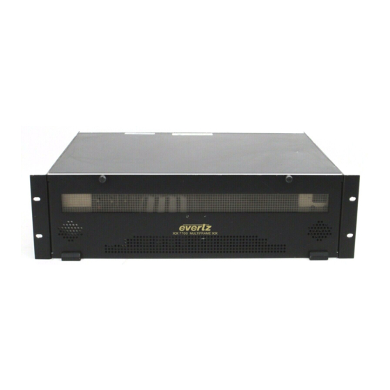
3 Rack Unit Frame
Brand: evertz
|
Category: Network Hardware
|
Size: 0 MB
Table of Contents

evertz 7700 Series Manual (14 pages)
HD-SDI Tri-Level Sync Generator
Brand: evertz
|
Category: Portable Generator
|
Size: 0 MB
Table of Contents

evertz 7700 Series Manual (14 pages)
Quad Analog Audio to Dual AES Converter
Brand: evertz
|
Category: Media Converter
|
Size: 0 MB
Table of Contents

evertz 7700 Series Manual (14 pages)
SDI Electrical to Optical Converter, 19.4Mb/s or 143-540Mb/s
Brand: evertz
|
Category: Media Converter
|
Size: 0 MB
Table of Contents

evertz 7700 Series Manual (12 pages)
AES to Analog Audio Converter
Brand: evertz
|
Category: Media Converter
|
Size: 0 MB
Table of Contents

evertz 7700 Series Manual (10 pages)
1 Rack Unit Frame
Brand: evertz
|
Category: Network Hardware
|
Size: 0 MB
Table of Contents


evertz 7700 Series Manual (12 pages)
SMPTE292M Re-Clocking Electrical to Fiber Converter
Brand: evertz
|
Category: Media Converter
|
Size: 0 MB
Table of Contents

evertz 7700 Series Manual (12 pages)
SMPTE259M Re-Clocking Electrical to Fiber Converter
Brand: evertz
|
Category: Media Converter
|
Size: 0 MB
Table of Contents

evertz 7700 Series Manual (10 pages)
Analog Audio to AES Converter
Brand: evertz
|
Category: Media Converter
|
Size: 0 MB
Table of Contents

evertz 7700 Series Manual (10 pages)
Equalizing Analog Video Distribution Amplifier
Table of Contents

evertz 7700 Series Manual (10 pages)
HDTV Optical to Electrical Converter, 19.4Mb/s to 1.5Gb/s
Brand: evertz
|
Category: Media Converter
|
Size: 0 MB
Table of Contents

evertz 7700 Series Quick Start Manual (10 pages)
High Amplitude Distribution Amplifier
Table of Contents

evertz 7700 Series Manual (8 pages)
Serial Digital Re-Clocking Distribution Amplifier
Table of Contents

evertz 7700 Series Manual (8 pages)
High Fanout Serial Digital Distribution Amplifier
Table of Contents


evertz 7700 Series Manual (15 pages)
HDTV AES Audio Embedder
Brand: evertz
|
Category: Network Hardware
|
Size: 0 MB
Table of Contents


evertz 7700 Series Manual (6 pages)
Remote Control Panel
Brand: evertz
|
Category: Remote Control
|
Size: 0 MB
Table of Contents

evertz 7700 Series Quick Start Manual (11 pages)
SDI Video Delay
Brand: evertz
|
Category: Recording Equipment
|
Size: 0 MB
Table of Contents

evertz 7700 Series Manual (6 pages)
Debug Kit
Brand: evertz
|
Category: Network Hardware
|
Size: 0 MB