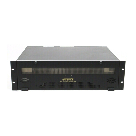
evertz 7700 Series Manual
Hide thumbs
Also See for 7700 Series:
- Manual (164 pages) ,
- Quick start manual (10 pages) ,
- Manual (65 pages)
Table of Contents
Advertisement
Quick Links
1. OVERVIEW...............................................................................................................................1
2. INSTALLATION........................................................................................................................3
3. SPECIFICATIONS ....................................................................................................................4
3.1. SIGNAL INPUT/OUTPUT .............................................................................................................. 4
3.2. SWITCHING .................................................................................................................................. 4
3.3. ELECTRICAL ................................................................................................................................ 4
3.4. PHYSICAL (NUMBER OF SLOTS)............................................................................................... 4
4. STATUS INDICATORS.............................................................................................................5
5. DOT-MATRIX DISPLAY ...........................................................................................................6
5.1. SELECTING THE CHANNEL........................................................................................................ 6
5.2. MONITORED PARAMETERS ....................................................................................................... 7
5.2.1.
DISPLAYING THE CARD TYPE....................................................................................... 7
5.2.2.
DISPLAYING THE FIRMWARE VERSION ...................................................................... 7
5.2.3.
DISPLAYING THE SELECTED CHANNEL ...................................................................... 7
6. JUMPER POSITIONS...............................................................................................................8
6.1. 7703R8X1/7703R16X1 JUMPERS................................................................................................ 8
BY THE GLOBAL FRAME STATUS............................................................................................. 8
6.3. CONFIGURING THE MODULE FOR FIRMWARE UPGRADES .................................................. 8
6.4. FACTORY AND BDM JUMPERS ................................................................................................. 9
®
Figures
Figure 1-1: 7703R8x1-RF & 7703R16x1-RF Block Diagram ...................................................................................2
Figure 2-1: 7703R8x1-RF & 7703R16x1-RF Rear Plates ........................................................................................3
Figure 6-1: Location of 7703R8x1 and 7703R16x1 Jumpers and LEDs..................................................................8
7703R8x1-RF & 7703R16x1-RF 8x1 Switch, 16x1 Switch, DC-3GHz
TABLE OF CONTENTS
? .............................................................................................................. 10
®
Control Screenshot ........................................................................................10
®
Revision 1.0
7700 MultiFrame Manual
Advertisement
Table of Contents

Summary of Contents for evertz 7700 Series
-
Page 1: Table Of Contents
7700 MultiFrame Manual 7703R8x1-RF & 7703R16x1-RF 8x1 Switch, 16x1 Switch, DC-3GHz TABLE OF CONTENTS 1. OVERVIEW..........................1 2. INSTALLATION........................3 3. SPECIFICATIONS ........................4 3.1. SIGNAL INPUT/OUTPUT ......................4 3.2. SWITCHING ..........................4 3.3. ELECTRICAL ..........................4 3.4. PHYSICAL (NUMBER OF SLOTS)....................4 4. - Page 2 Oct 09 Information contained in this manual is believed to be accurate and reliable. However, Evertz assumes no responsibility for the use thereof nor for the rights of third parties, which may be affected in any way by the use thereof. Any representations in this document concerning performance of Evertz products are for informational use only and are not warranties of future performance, either expressed or implied.
-
Page 3: Overview
7700 MultiFrame Manual 7703R8x1-RF & 7703R16x1-RF 8x1 Switch, 16x1 Switch, DC-3GHz OVERVIEW The 7703R8x1 and 7703R16x1 are bi-directional, low loss switches for signals from DC to 3GHz. The 7703R8x1 is an 8x1 switch while the 7703R16x1 is a 16x1 switch. Control of the switch may be done locally at the card-edge with the built-in rotary encoder and dot-matrix display, or remotely through SNMP/VistaLINK ®. -
Page 4: Figure 1-1: 7703R8X1-Rf & 7703R16X1-Rf Block Diagram
7700 MultiFrame Manual 7703R8x1-RF & 7703R16x1-RF 8x1 Switch, 16x1 Switch, DC-3GHz 8x1 Switch on 7703R8x1-RF 16x1 Switch on 7703R16x1-RF Common VistaLINK Dot Matrix Display Interface Monitoring & Control Rotary Encoder LED Indicators Figure 1-1: 7703R8x1-RF & 7703R16x1-RF Block Diagram Page - 2 Revision 1.0... -
Page 5: Installation
7700 MultiFrame Manual 7703R8x1-RF & 7703R16x1-RF 8x1 Switch, 16x1 Switch, DC-3GHz INSTALLATION The 7703R8x1-RF & 7703R16x1-RF come with a companion rear plate that occupies two slots in the frame. For information on inserting the module into the frame see the 7700FR chapter section 3. Figure 2-1: 7703R8x1-RF &... -
Page 6: Specifications
7700 MultiFrame Manual 7703R8x1-RF & 7703R16x1-RF 8x1 Switch, 16x1 Switch, DC-3GHz SPECIFICATIONS 3.1. SIGNAL INPUT/OUTPUT Number of Ports: 8 + 1 Common 7703R8x1: 16 + 1 Common 7703R16x1: BNC per IEC 61169-8 Annex A Connector Type: (F-Type optional) 75Ω Impedance: DC - 3GHz Bandwidth: Insertion Loss:... -
Page 7: Status Indicators
7700 MultiFrame Manual 7703R8x1-RF & 7703R16x1-RF 8x1 Switch, 16x1 Switch, DC-3GHz STATUS INDICATORS The 7703R8x1-RF & 7703R16x1-RF have two LED status indicators on the main circuit-board front card edge to show the operational status of the card at a glance. These two large LEDs on the front of the board indicate the general health of the module. -
Page 8: Dot-Matrix Display
7700 MultiFrame Manual 7703R8x1-RF & 7703R16x1-RF 8x1 Switch, 16x1 Switch, DC-3GHz DOT-MATRIX DISPLAY Status monitoring and control of the card’s parameters are provided via the four-digit alphanumeric display located on the card edge. The card-edge control knob (see Figure 6-1) is used to navigate through the display menus and pressing this knob selects options. -
Page 9: Monitored Parameters
7700 MultiFrame Manual 7703R8x1-RF & 7703R16x1-RF 8x1 Switch, 16x1 Switch, DC-3GHz 5.2. MONITORED PARAMETERS To view the monitored parameters, select the MON menu item in menu level 1. The control knob may then be used to select the parameter to view as described below: 5.2.1. -
Page 10: Jumper Positions
7700 MultiFrame Manual 7703R8x1-RF & 7703R16x1-RF 8x1 Switch, 16x1 Switch, DC-3GHz JUMPER POSITIONS 6.1. 7703R8X1/7703R16X1 JUMPERS LOCAL FAULT / MODULE OK CONTROL KNOB FACTORY FRAME STATUS Serial Upgrade Port Figure 6-1: Location of 7703R8x1 and 7703R16x1 Jumpers and LEDs 6.2. SELECTING WHETHER LOCAL FAULTS WILL BE MONITORED BY THE GLOBAL FRAME STATUS The FRAME STATUS jumper J3 determines whether local faults (as shown by the Local Fault indicator) -
Page 11: Factory And Bdm Jumpers
6.4. FACTORY AND BDM JUMPERS When shipped from the Evertz facility, the FACTORY and BDM jumpers will not be installed. These jumpers should not be installed for any reason. If jumpers are on these positions they should be removed. -
Page 12: Vistalink ® Remote Monitoring/Control
WHAT IS VISTALINK ® VistaLINK is Evertz’s remote monitoring and configuration platform which operates over an Ethernet ® network using Simple Network Management Protocol (SNMP). SNMP is a standard computer network protocol that enables different devices sharing the same network to communicate with each other.


Need help?
Do you have a question about the 7700 Series and is the answer not in the manual?
Questions and answers