Sign In
Upload
Manuals
Brands
evertz Manuals
Control Unit
7700 MultiFrame
evertz 7700 MultiFrame Manuals
Manuals and User Guides for evertz 7700 MultiFrame. We have
17
evertz 7700 MultiFrame manuals available for free PDF download: User Manual, Manual
evertz 7700 MultiFrame User Manual (172 pages)
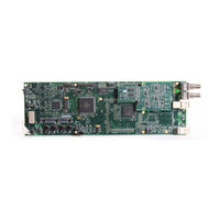
Dual HDTV Up/Down/Cross Converters
Brand:
evertz
| Category:
Media Converter
| Size: 3 MB
Table of Contents
Table of Contents
5
Overview
15
Table 1-1: Control Interface Differences between 7814 Converters Depending on Product
15
Table 1-2: Control Interface Differences between 7814 Converters Depending on Product
15
Variation/Ordering Options
15
Functional Description
18
Figure 1-1: 7814 Series Block Diagram (-HD, -3G and -AES8 Versions)
19
Figure 1-2: 7814 Series Audio Block Diagram (-AES8 Versions)
20
Product Options
21
Variation/Ordering Options
22
Installation
23
Figure 2-1: 7814XXX-XX-2 Rear Plate Layout & 7814XXX-AES8-XX-2 Rear Plate Layout
23
Figure 2-2: 7814XXX-XX-F-2 Rear Plate Layout & 7814XXX-AES8-XX-F-2 Rear Plate Layout
24
Input/Output Connections
25
Ethernet Connections
26
Figure 2-4: Colour Code Wiring for the Current RJ 45 Standards
26
Gpio Connector
27
Table 2-1: GPIO Connector Pin out
27
Figure 2-5: GPI Input Circuitry
28
Figure 2-6: GPO Output Circuitry
28
Aes Inputs
29
Table 2-2: AES Input Audio Connector Pin out
29
Aes Outputs
30
Table 2-3: AES Output Audio Connector Pin out
30
Specifications
31
Serial Digital Video Input
31
Serial Digital Video Output
31
Reference Video Input
31
General Purpose Inputs and Outputs
32
Aes Inputs
32
Aes Outputs
32
Electrical
32
Physical
32
Status Leds
33
Module Status Leds -Aes8 Version and Non -Aes8 Versions
33
Figure 4-1: Status Leds
33
Module Control
35
Control Categories
35
Figure 5-1: Navigation Tree
35
Figure 5-2: High Level Card Controls
35
Figure 5-3: Path 1 and 2 Processing Path
37
High Level Card Controls
41
General Control Tab
41
Figure 6-1: High Level Card Controls
41
Figure 6-2: Misc Faults Tab
41
Reference Control Tab
42
Genlock Control
42
Figure 6-3: Genlock Source Control
42
Global Status
43
Global Genlock Traps
43
Auto Reference Fail-Over
43
Figure 6-4: Prioritized Reference Fail over Options
43
Ip Control Tab
46
IP Configuration through Vlpro
46
IP Configuration through Serial Com Port (Not Implemented at Time of Writing)
46
Figure 6-5: IP Control
46
Change Product Tab
47
Directly Set
47
Script Set
47
Figure 6-6: Change Product Tab
47
Gpio Control Tab
48
Gpio 1
48
Fiber Control Tab (-F Option Only)
49
Fiber Rx
49
Fiber Tx
49
Trap Status
49
Configuring the Video Path Controls
51
Figure 7-1: Video Tab
51
Video Control Tab
52
Figure 7-2: Video Tab
52
Video Control
53
Video Monitor
57
Video Traps
57
Video Processing Tab
58
Figure 7-3: Video Proc Tab
58
Video Proc
59
Colour Legalize Tab (+Icl2)
61
Colour Legalize
61
Figure 7-4: Colour Legalize Tab
61
Image Enhancement Tab
63
Image Enhancement
63
Figure 7-5: Image Enhancement Tab
63
Noise Reduction Tab
65
Temporal Noise Reduction Levels
65
Figure 7-6: Noise Control Tab
65
Deinterlacer Control Tab
66
Interlacer Control
66
Figure 7-7: Deinterlacer Control Tab
66
Deinterlacer Status
68
Afd Tab
69
AFD Control
69
Figure 7-8: AFD Control Tab
69
AFD Present Traps
71
Afd Monitor Tab
72
SMPTE2016-1 Monitor
72
Figure 7-9: SMPTE2016-1 Monitor Tab
72
Sd Aperture Control Tab
73
SD Aperture Control
73
Figure 7-10: SD Aperture Control Tab
73
Figure 7-11: SD Aperture Control
74
User Arc
75
ARC Configuration
75
Figure 7-12: User AFD Tab
75
Conversion Controls
76
Figure 7-13: Image Cropping and Output Image Size
78
Afd Arc Controls
79
Figure 7-14: AFD ARC Tab
79
AFD Select
80
Figure 7-15: AFD Select
80
AFD Stamp
81
AFD Stamp Settings
81
Figure 7-16: AFD Code Description
81
Conversion Settings
82
Figure 7-17: Pictorial Representation
82
Figure 7-18: Conversion Screen
82
Scaler Tab
84
Figure 7-19: Scaler Tab
84
Slew Settings
85
Colour Controls
85
Filter Settings
86
AFD Stamp Settings
86
Figure 7-20: Pictorial Representation
87
Conversion Settings
88
Figure 7-21: Aspect Ratio Conversion
88
7814 Audio Architecture
90
Figure 7-22: Internal 7814 Series Audio Architecture
91
Audio Tab
92
Audio Control
92
Figure 7-23: Audio Tab
92
Audio Monitor Settings
94
Audio Present Traps
94
Embedded Audio Input Correction Tab
95
Channel X
95
Figure 7-24: Audio Input Correction Tab
95
Aes Audio Input Correction Tab
96
Channel X
96
Advertisement
evertz 7700 MultiFrame Manual (58 pages)
Brand:
evertz
| Category:
Computer Hardware
| Size: 0 MB
Table of Contents
Table of Contents
1
Overview
7
Functional Description
8
Figure 1-1: 7730ADC Block Diagram
9
Figure 1-2: 7730ADC-A4 Block Diagram
9
Figure 1-3: 7730ADC-AES Block Diagram
10
Installation
11
Video in and out
11
Figure 2-1: 7730ADC Rear Panels
11
Specifications
12
Analog Video Input
12
Reference Video Input
12
Analog Video Output
12
Serial Video Output
12
Video Performance (Sdi Outputs Only)
13
Analog Audio Input (-A4 Only)
13
Aes Audio Inputs (-Aes Only) and Outputs
13
Electrical
13
Physical
14
Status Leds
15
Module Status Leds
15
Audio Status Leds
15
Table 4-1: Audio Channel Status Leds
15
Rgb Video Level Calibration
16
Audio Buffer Management (+S Option Only)
17
Audio Levels, Headroom, Clipping and the Bar Graphs (-A4 and -Aes)
18
Input Audio Level Calibration
18
Audio Alarm Calibration Procedure (-A4 and -Aes)
19
Calibrate Audio Silence Detection
19
Calibrate Audio Phase Reversal Detection
19
Calibrate Audio Mono Detection
20
Define the Fault Condition(S)
20
On Screen Menus
21
Navigating the on Screen Menu System
21
Changing Text Fields
21
On Screen Display - Main Menu
22
Configuring the Audio Controls (-A4 and -Aes)
22
Selecting the Audio Destination Group
23
Audio Freeze Mode
23
Additional Audio Delay
24
Monitoring the Audio Buffer Tracking
24
Setting the Analog Levels (-A4 Only)
24
Audio Channels 1 and 2 Processing
25
Audio Channels 3 and 4 Processing
25
Swapping Channel Pairs
25
Configuring the Video Controls
26
Setting the Video Standard
27
Selecting the Input Video Synchronization Source
27
Selects the Action to Take When Input Video Is Missing
27
Genlock Source Selection
28
Setting the Free-Running Frequency
28
Setting the Horizontal Phase of the Output Video - NTSC/525 Video
28
Setting the Horizontal Phase of the Output Video - PAL-B/625 Video
29
Monitoring the Horizontal Delay between the Input and Output Video
29
Setting the Vertical Phase of the Output Video - NTSC/525 Video
29
Setting the Vertical Phase of the Output Video - PAL-B/625 Video
29
Monitoring the Vertical Delay between the Input and Output Video
29
Monitoring the Audio Buffer Tracking
30
Selecting Time Code Type
30
Setting the VITC Line Number - 525 Line Video
30
Setting the VITC Line Number - 625 Line Video
30
Configuring the Input Video Processing Controls
31
Black Level Control
31
Video Level Control
32
Delay Y/G
32
Fine Phase
32
Configuring the Bar Graph Controls (-A4 and -Aes)
32
Selecting the Bar Graph Operating Mode
33
Setting the Headroom
34
Setting the Bar Graph Type
34
Setting the PPM Mode and Ballistics
35
Table 9-1: PPM Bar Graph Characteristics
35
Setting the VU Display Range
36
Setting the Phase Bar Graph Type
36
Setting the Bar Graph Error Region
36
Setting the Bar Graph Warning Region
37
Setting the Level Bar Graph Scale Position
37
Setting the Phase Bar Graph Scale Position
37
Setting the Window and Bar Graph Positions
37
Setting the Colours of the Bar Graphs
38
Setting the Level Bar Graph Region Colour
38
Setting the Level Bar Graph Size
39
Setting the Transparency (Opacity) of Bar Graph Background
39
Setting the Transparency (Opacity) of the Bar Graph Bars
39
Configuring the On-Screen Display Controls
39
Descriptions of the on Screen Windows
40
Video/Audio Status
40
Time Code Window
41
Fault Message Windows
41
Table 9-2: Video/Audio Status Screen Items
41
Setting the Position of on Screen Windows
42
Setting the Horizontal Position of on Screen Windows
42
Setting the Vertical Position of on Screen Windows
42
Setting the Position of the Bar Graphs
42
Setting the Horizontal Position of the Bar Graphs
42
Setting the Vertical Position of the Bar Graphs
42
Selecting What Bar Graphs and Windows to Display
43
Setting the Text Window Attributes
43
Turning on the Text Window Backgrounds
43
Table 9-3: Methods of Turning Windows and Bar Graphs on and off
43
Setting the Text Window Background Colours
44
evertz 7700 MultiFrame Manual (52 pages)
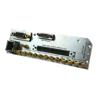
HD-SDI/SD-SDI Audio Embedder with Dobly Encoder
Brand:
evertz
| Category:
Media Converter
| Size: 0 MB
Table of Contents
Table of Contents
1
Revision History
5
1 Overview
7
Figure 1-1: 7721AE8-DEE-HD Block Diagram
8
2 Installation
9
Video Connections
9
Figure 2-1: 7721AE8-DEE-HD Rear Panel
9
Video Reference
10
Aes Input and Output Audio Connections
10
Table 2-1: AES in Audio Connector Pin Assignments
10
Table 2-2: AES out Audio Connector Pin Assignments
11
Table 2-3: AES Audio Breakout Cable (Evertz Part # WPAES8-BNCM-6F) Pin Assignments
11
Metadata I/O
12
General Purpose Inputs and Outputs
12
Table 2-4: Metadata Transmit or Receive Pin Assignments
12
3 Specifications
13
Serial Digital Video Inputs
13
Serial Digital Video Outputs
13
Video Reference Input
13
Aes Audio Inputs
13
Aes Audio Outputs
14
Metadata Input/Output
14
Headphone Audio Outputs
14
Delay
14
Electrical
14
Physical
14
4 Status Indicators
15
General Leds
15
Diagnostic and Menu Leds
15
Figure 4-1: Status LED Locations
15
Embedded Audio Status Leds
16
Table 4-1: Audio Group Status Leds
16
Table 4-2: AES Input Channel Presence Leds
17
5 Card Edge Controls
18
Figure 5-1: Card Edge Controls
18
6 Card Edge Menu System
19
Navigating the Menu System
19
Top Level Menu Structure
19
Table 6-1: Top Level Menu Structure
19
Configuring the Video Controls
20
Setting the Video Standard
20
Table 6-2: Video Controls Menu
20
Setting the Vertical Phase
21
Setting the Horizontal Phase
21
Setting the Frame Phase
21
Setting the Action to Take When Input Video Is Missing
21
Configuring the Audio Controls
22
Setting the Coarse Audio Delay
22
Setting the Fine Audio Delay
22
Table 6-3: Audio Controls Menu
22
Setting the SRC Mode
23
Setting the C-Bit Control
23
Enabling the Audio Embedders
23
Setting the Demux Loss of Video Mode
24
Configuring the Video Processing Functions
24
Setting the Black Level
24
Setting the Luma Gain
24
Setting the Chroma Gain
24
Table 6-4: Video Processor Menu
24
Setting the Hue
25
Understanding the Audio Processor
25
Single Mixer
25
Figure 6-1: Single Mixer Stage
25
Full Mixer
26
Figure 6-2: Full Mixer
26
Mixer A, B and Dolby-E Encoder
27
Figure 6-3: Mixer a and B and Dolby-E Encoder Routing
27
Mono Mixer
28
Figure 6-4: Mono-Mixers
28
Headphone Monitoring
29
Configuring the Audio Processing Functions
29
Figure 6-5: Headphone Monitoring
29
Table 6-5: Audio Processor Menu
29
Selecting Input Source for Mixer a
30
Selecting the Source for Channel 1 a of Mixer a
31
Setting the Gain of the Input Sources for Mixer a
32
Setting the Gain for Channel 1 a of Mixer a
32
Setting the Inversion Control of the Input Sources for Mixer a
33
Setting the Inversion Control for Channel 1 a of Mixer a
33
Dolby-E Encoder Output Routing
34
Output Selection Control
34
Configuring the Headphone Monitor
34
Setting the Headphone Volume
34
Selecting the Source for the Headphone Monitoring
35
Understanding the Dolby Encoder on this Product
35
Understanding Dolby-E Program Configuration
36
Understanding Dolby-E Frame Rates & Packet Phasing
37
Table 6-6: Channel Mappings and Program Configurations
37
Figure 6-6: Dolby-E Frame Alignment
38
Figure 6-7: Dolby-E Frame Alignment and 720P Video Without Reference
38
Configuring the Dolby Encoder
39
Setting the Controls for Dolby Decoder a
39
Figure 6-8: Dolby-E Frame Alignment and 720P Video with Reference
39
Dolby Encoder Automatic Program Configuration Selection
40
Dolby-E Encoder Video Sync Source Select
40
Dolby-E Output Line Phase Adjust
40
Configuring the Metadata
40
Selecting the Type of Metadata that Is Output from Metadata Decoder a
41
Setting the Controls for Metadata
41
Configuring the VANC Metadata De-Embedder
42
Selecting the Type of Metadata that Is Inserted into VANC
42
Vanc
42
Configuring the VANC Metadata Embedder
43
Configuring the External Metadata I/O
44
Selecting Metadata Source for Dolby-E Encoder
44
Displaying the Module Status
45
Checking FPGA 1 Revision
45
Checking FPGA 2 Revision
45
Checking the Input Video Standard
45
Checking the Module Firmware
45
Table 6-7: Status Menu Parameters
45
Checking the Output Video Standard
46
Configuring Miscellaneous Parameters
46
Enabling Vistalink® Control of the Module
46
Setting Card Edge Display Orientation
46
Table 6-8: Miscellaneous Menu Parameters
46
Resetting the Module to Factory Settings
47
Resetting the Module to Its Factory Defaults
47
Advertisement
evertz 7700 MultiFrame Manual (40 pages)
3G/HD/SD-SDI Intelligent Distribution Amplifier (1x8)
Brand:
evertz
| Category:
Amplifier
| Size: 0 MB
Table of Contents
Table of Contents
1
Overview
7
Figure 1-1: 7800IDA8-3G Block Diagram
8
Figure 1-2: 7800IDA8-3G+IG Block Diagram
8
Figure 1-3: 7800IDA8-3G+UMX Block Diagram
9
Figure 1-4: 7800IDA8-3G+DMX Block Diagram
9
Installation
10
Figure 2-1: 7800IDA8-3G Rear I/O Module
10
Specifications
11
Serial Video Input
11
Serial Video Outputs
11
Electrical
11
Physical
11
Status Leds
12
Figure 4-1: Status Leds
12
Card Edge Module Control
13
Card-Edge Control
13
Navigating the Card-Edge
13
Card-Edge Menu Structure
13
Setting the Display Orientation
13
Preset Parameters
14
Saving Presets
14
Loading Presets
14
Video Parameters
14
Forcing a Video Standard
14
Viewing the Input Video Standard
14
Vistalink ® Module Control
15
What Is Vista Link
15
General
16
Figure 6-1: General Tab
16
Video Control
17
Viewing the Detected Video Standard
17
Audio Control (+Umx, +Ig and +DMX Only)
17
C-Bit Control
17
Figure 6-2: Video Control Tab
17
Figure 6-3: Audio Control Tab
17
Mixer Control (+Umx, +Ig and +DMX Versions Only)
18
Source X/Y
18
Figure 6-4: Mixer Control 1-4 Tab
18
Figure 6-5: Source Select Drop down Menu
19
Gain Adjust X
20
Invert Enable X
20
Preset Control
20
Saving Presets
20
Loading Presets
20
Preset Control
21
AVM Trigger Logic
21
Figure 6-6: Preset Control Tab
21
Trigger Assert Preset
22
Trigger De-Assert Preset
22
Down MIX Control (+DMX Only)
24
Setting the Source Select Controls
24
Figure 6-7: Downmix Control Tab
24
Setting the down MIX Type Controls
25
Setting the Output Scaling Mode
25
Setting the Output Gain
26
Setting the LFE Mixing Control
26
Setting the Surround Phase Control
26
Setting the down MIX Type Control
26
Custom down MIX Type Control Settings
27
Upmix Control (+Umx Only)
28
Setting the Upmix Mode
28
Figure 6-8: Upmix Control Tab
28
Setting the Centre Width
29
Setting the Surround Depth
29
evertz 7700 MultiFrame Manual (38 pages)
Eight Channel SDI + Ethernet SONET I SDH Fiber Transceiver
Brand:
evertz
| Category:
Transceiver
| Size: 0 MB
Table of Contents
Table of Contents
1
Overview
5
Figure 1-1: 7707VB-8-OC48 Block Diagram
7
Installation
8
Figure 2-1: 7707VB-8-OC48 Rear Panel
8
Care and Handling of Optical Fiber
9
Safety
9
Assembly
9
Labeling
9
Handling and Connecting Fibers
10
Figure 2-2: Reproduction of Laser Certification and Identification Label
10
Specifications
11
Serial Video Input
11
Serial Video Outputs
11
Serial Video Monitor Outputs
11
Optical Output
11
Optical Input
12
Electrical
12
Physical
12
Compliance
12
Status Indicators and Displays
13
Status Indicator Leds
13
Figure 4-1: Location of Status Indicators and Controls
13
Card Edge Display
14
STAT Menu
14
Figure 4-2: STAT Menu Structure
15
Displaying of Warning Status Indications
16
Displaying the Optical Link Data Standard
16
Displaying Optical Power
16
Displaying the Link Output Reference Clock Source
16
Displaying the Current Time Interval and the Current Interval Counter
17
Displaying the Last Interval Counter
18
Displaying the Errored Seconds Ratio
19
Displaying the Loss of Signal Seconds in Line Layer
19
Displaying the Link Input Status
19
Displaying the TDM Data Errors
20
Displaying the Video Standard at Output Ports
20
Detecting the EDH Presence in a Compatible Signal at Output Ports
20
Displaying the Sdti Status at Output Ports
21
Displaying the Video Standard at Input Ports
21
Detecting the EDH Presence in a Compatible Signal at Input Ports
21
Displaying the SDTI Status at Input Ports
22
Displaying the Ethernet Status
22
Displaying the Ethernet Speed
22
Flexible Bandwidth Management Monitoring
23
Displaying the Firmware Version
23
Control Menu
24
Figure 4-4: Control Menu
24
Setting the Optical Link Standard
25
Setting the Behavior of Laser When There Is no Applied Video
25
evertz 7700 MultiFrame Manual (34 pages)
Dual Wideband RF Fiber Transmitter
Brand:
evertz
| Category:
Transmitter
| Size: 0 MB
Table of Contents
Table of Contents
1
Overview
7
Figure 1-1: 7807LT-2 Block Diagram
8
Installation
9
Figure 2-1: 7807LT-2 Module
9
7807Lt-2 Connections
10
Care and Handling of Optical Fiber
11
Safety
11
7807LT-2 1310Nm FP and CWDM Versions
11
Assembly
11
Labeling
11
Handling and Connecting Fibers
12
Specifications
13
Rf Input
13
Rf Monitor Output
13
Optical Output
13
General Purpose Outputs
13
Electrical
13
Physical (Number of Slots)
14
Compliance
14
Rf System Performance 7807Lt-2+7807Lr-2 Pair
14
Status Indicators
15
Table 4-1: LED Status Indicators
17
Jumer Positions
18
7807Lt-2 Jumpers and Leds
18
Selecting Whether Local Faults will be Monitored by the Global Frame Status
18
Figure 5-1: Location of 7807LT-2 Jumpers and Leds
18
Configuring the Module for Firmware Upgrades
19
Factory and Bdm Jumpers
19
Gpo Jumpers
19
7807LT-2 Dual Wideband RF Fiber Transmitter
19
Dot-Matrix Display
20
Figure 6-1: Card Edge Menu Structure
23
7807Lt-2 Controlled Parameters
24
Adjusting the RF Input Power Alarm
24
Selecting the Input Gain Mode
24
Enabling/Disabling Squelch Mode
25
Adjusting the Squelch Mode Threshold
25
Adjusting the RF Gain
25
Adjusting the AGC Target Level
26
Setting the Passcode (DWDM Versions Only)
26
Setting the LNB Voltage Level
26
Configuring the 22Khz Tone
27
Setting the LNB Current Threshold Level
27
Default Card-Edge Display
27
Setting the Display Orientation
28
Displaying the RF Threshold
28
Displaying the Gain Mode
28
Displaying the Gain Level
28
Displaying the Squelch Status
28
evertz 7700 MultiFrame Manual (32 pages)
Wideband RF Fiber
Brand:
evertz
| Category:
Transmitter
| Size: 0 MB
Table of Contents
Table of Contents
1
Overview
7
Figure 1-1: 7708LT Block Diagram
8
Installation
9
Figure 2-1: 7708LT Module
9
7708Lt Connections
10
Care and Handling of Optical Fiber
10
Safety
10
7708LT 1310Nm FP and CWDM Versions
10
7708LT DWDM Versions
10
Assembly
11
Labeling
11
Figure 2-2: Reproduction of 7708LT Certification and Identification Label for Models that Are Class 1 Laser Products
11
Figure 2-3: Reproduction of 7708LT Certification and Identification Label for Models that Are Class 1M Laser Products
11
Handling and Connecting Fibers
12
Specifications
13
Rf Input
13
Rf Monitor Output
13
Optical Output
13
Electrical
13
Physical (Number of Slots)
13
Compliance
14
Rf System Performance 7708Lt13+7708Lra Pair
14
Status Indicators
15
Table 4-1: LED Status Indicators
16
Jumer Positions
17
7708Lt Jumpers and Leds
17
Selecting Whether Local Faults will be Monitored by the Global Frame Status
17
Configuring the Module for Firmware Upgrades
17
Figure 5-1: Location of 7708LT Jumpers and Leds
17
Factory and Bdm Jumpers
18
Dot-Matrix Display
19
Figure 6-1: Card Edge Menu Structure
21
7708Lt Controlled Parameters
22
Adjusting the RF Input Power Alarm
22
Selecting the Input Gain Mode
22
Enabling/Disabling Squelch Mode
23
Adjusting the Squelch Mode Threshold
23
Adjusting the RF Gain
23
Adjusting the AGC Target Level
24
Setting the Passcode (DWDM Versions Only)
24
Setting the LNB Voltage Level
24
Configuring the 22Khz Tone
25
Setting the LNB Current Threshold Level
25
Default Card-Edge Display
25
Setting the Display Orientation
25
Displaying the RF Threshold
26
Displaying the Gain Mode
26
Displaying the Gain Level
26
Displaying the Squelch Status
26
evertz 7700 MultiFrame Manual (26 pages)
Brand:
evertz
| Category:
Transmitter
| Size: 0 MB
Table of Contents
Table of Contents
1
Overview
5
Figure 1-1: 7707VAT-HD Block Diagram
6
Installation
7
Video Signal Connections
7
Figure 2-1: 7707VAT-HD Rear Panel
7
Aes Audio Connections (Model 7707Vat-Hd)
8
Aes Audio Connections (Model 7707Vat-U-Hd)
8
Optical Signal Connections
8
Care and Handling of Optical Fiber
9
Safety
9
Assembly
9
Labeling
9
Figure 2-2: Reproduction of Laser Certification and Identification Label
9
Handling and Connecting Fibers
10
Specifications
11
Serial Digital Video Input
11
Serial Digital Video Output
11
Aes Audio Inputs
11
Optical Output
12
Video Lock Time
12
Electrical
12
Compliance
12
Physical
12
Status Indicators and Displays
13
Status Indicator Leds
13
Figure 4-1: Location of Jumpers and Card Edge Controls
13
Dot-Matrix Display and Controls
14
Figure 4-2: Card-Edge Menu Quick Reference
15
Display of Warning Status Indications
16
Displaying the Input Video Standard
16
Displaying the Input Equalization Strength
17
Displaying the Status of Input Video Embedded Audio Groups
17
Displaying the AES Audio Sample Rate
17
7707VAT-HD HD/SDI Video and AES Audio Fiber Transmitter
17
Displaying the Software Version
18
Selecting the Output Video Standard
18
Selecting Audio Embedding Group
19
Selecting the Output Video When the Signal Is Lost
20
Selecting the COAX Mode
20
Selecting the Output Laser Enable Mode
21
Selecting Input Video Cleaning
21
Selecting Video Error Detection
22
Selecting AES Sample Rate Conversion
22
Selecting Audio Error Detection
22
Selecting the Headphone Monitoring Jack Channel
23
Setting the Orientation of the Display
23
Selecting the Factory Reset Configuration
23
Jumper Controls
24
Selecting Whether Local Faults will be Monitored by the Global Frame Status
24
evertz 7700 MultiFrame User Manual (32 pages)
7800DA2T-3G 3G/HD/SD-SDI Distribution Amplifier
Brand:
evertz
| Category:
Computer Hardware
| Size: 0 MB
Table of Contents
Table of Contents
5
Overview
9
Figure 1-1 : 7800DA2T-3G Block Diagram
10
Installation
11
Figure 2-1 : 7800DA2T-3G/7800DA2T-HD Rear Panels
11
Specifications
13
Serial Video Input
13
Serial Video Outputs
13
Electrical
14
Physical
14
Status Leds
15
Figure 4-1 : Status Leds
15
Card Edge Module Control
17
Card-Edge Control
17
5.1.1. Navigating the Card-Edge
17
Card-Edge Menu Structure
17
Setting the Display Orientation
17
Preset Parameters
18
5.4.1. Saving Presets
18
5.4.2. Loading Presets
18
Vistalink ® Module Control
19
What Is Vistalink
19
General
20
6.2.1. Information
20
Figure 6-1 : Vistalink PRO - General Section
20
Video Control
21
Figure 6-2 : Vistalink PRO - Video Control Section
21
Presets Control
22
6.4.1. Presets
22
Figure 6-3 : Vistalink PRO - Presets Control Section
22
Monitor
23
6.5.1. Video Status
23
Figure 6-4 : Vistalink PRO - Monitor Section
23
Input 1 Fault Traps
24
Figure 6-5 : Vistalink PRO - Input 1 Fault Traps Section
24
Input 2 Fault Traps
25
Figure 6-6 : Vistalink PRO - Input 2 Fault Traps Section
25
Jumpers and User Adjustments
27
Selecting Whether Local Faults will be Monitored by the Global Frame
27
Status
27
Configuring the Module for Firmware Upgrades
27
Figure 7-1 : LED and Jumper Locations
27
Upgrade Procedures
29
Upgrade Firmware
29
PRO - Version Information Selection
29
Updating Vlpro Server Jar File
30
Figure 8-2 : Vistalink
30
Figure 8-3 : Vistalink
30
PRO - Version Information Window
30
PRO - Upgrade Firmware Window
30
Figure 8-4 : Vistalink PRO Server/Apply Update
31
Figure 8-5 : Vistalink PRO - Applying JAR Updates
31
evertz 7700 MultiFrame Manual (28 pages)
Multi-Signal HD/SD, AES, and Control Fiber Receiver
Brand:
evertz
| Category:
Receiver
| Size: 0 MB
Table of Contents
Table of Contents
1
Overview
5
Figure 1-1: 7707MRA-HD Block Diagram
6
Installation
7
Figure 2-1: 7707MRA-HD Rear Plates & Pin out
7
Electrical Signal Connections
8
Figure 2-2: 7707MRA-HD Rear Plates & Pin out (1RU Version)
8
Optical Signal Connections
9
Single Fiber Version
9
Dual Fiber Versions
10
Care and Handling of Optical Fiber
10
Safety
10
Assembly
11
Labeling
11
Handling and Connecting Fibers
11
Figure 2-3: Reproduction of Laser Certification and Identification Label
11
Specifications
12
Serial Digital Video Output
12
Aes Audio Outputs
12
Serial Data
12
General Purpose Inputs
13
General Purpose Outputs
13
Optical Inputs/Outputs
13
Electrical
13
Physical
13
Status Indicators and Displays
14
Status Indicator Leds
14
Figure 4-1: Location of Status Indicators and Jumpers
14
Dot Matrix Display
15
Figure 4-2: Card Edge Menu Structure
16
Displaying Warning Status Indications
17
Displaying the Standard of Input Video
17
Displaying the Embedded Audio Status of Input Video
18
Displaying the GPI Status
18
Displaying the GPO Status
18
Displaying the Received Optical Power
19
Displaying the Firmware Version
19
Selecting the Laser Output Mode on LOS
19
Selecting the Video Output Mode on LOS
20
Selecting Output Video HANC Cleaning
20
Selecting Balanced or Unbalanced Audio
20
Selecting AES Pop-Reduction and Generation on LOS
21
Selecting the Serial Data Type
21
Selecting the Serial Data Rate
22
Selecting the Serial Data Fail Safe Bias
22
Selecting Audio De-Embedding Groups
23
Selecting Serial Data De-Embedding Parameters
23
Selecting GPIO De-Embedding Parameters
24
Selecting Fiber Input Error Detection
25
Selecting the Headphone Monitoring Jack Channel
25
evertz 7700 MultiFrame Manual (26 pages)
VistaLINK third party interface module
Brand:
evertz
| Category:
Control Unit
| Size: 0 MB
Table of Contents
Table of Contents
1
Revision History
3
1 Overview
5
2 Installation
6
Figure 1-1: 7700TPI Block Diagram
6
Connecting Gpi/Gpo, Rs-232/422 Interfaces
7
Figure 2-1: 7700TPI Rear I/O Module and Pinout Assignments
7
Table 2-1: Upper Left 2X6 Terminal Block Connector Pin Assignments
8
Table 2-2: Lower Left 2X17 Terminal Block Connector Pin Assignments
9
General Purpose Inputs & Outputs
10
Table 2-3: Lower Right 2X17 Terminal Block Connector Pin Assignments
10
Configuring the Module over an Rs-232 Serial Connection
11
Figure 2-2: Typical GPI Circuitry
11
Figure 2-3: Typical GPO Circuitry
11
Figure 2-4: 7700TPI Main Menu
12
Table 2-4: 7700TPI Configuration COM Settings
12
Figure 2-5: 7700TPI Network Configuration Menu
13
Network Configuration Menu
13
Figure 2-6: 7700TPI SNMP Configuration Menu
14
SNMP Configuration Menu
14
Auxiliary Serial Port Configuration Menu
15
Figure 2-7: 7700TPI Auxiliary Serial Port Configuration Menu
15
3 Specifications
16
General Purpose Interface Inputs
16
General Purpose Interface Outputs
16
Data Input Serial Port
16
Electrical
16
Physical
16
4 Status Indicators
17
Figure 4-1: LED Status Indicators and Card Edge Controls
17
5 Card Edge Controls
18
Figure 5-1: Card Edge Controls
18
6 Location of Leds and Jumpers
19
Selecting Whether Local Faults will be Monitored by the Global Frame Status
19
Configuring the Module for Firmware Upgrades
19
Figure 6-1: LED and Jumper Locations
19
Upgrading the Firmware Using FTP
20
Determine the IP Address of the Module
20
Establishing a Valid Network Connection
20
Figure 6-2: Opening a DOS Command Window
20
FTP Upgrade
21
Figure 6-3: Pinging a 7700TPI Module
21
Figure 6-4: FTP Upgrading a 7700TPI Module
22
Completing the FTP Upgrade
23
Upgrading the Firmware over an RS-232 Serial Connection
23
Controlling Gpi Pullup Voltage
23
7 Vistalink ® Remote Monitoring/Control
24
What Is Vista Link
24
Vista Link ® Monitored Parameters
24
Ista Link Controlled Parameters
24
Table 7-1: Vistalink
24
Table 7-2: Vistalink
24
Monitored Parameters
24
Vista Link ® Traps
25
Table 7-3: Vistalink
25
Traps
25
evertz 7700 MultiFrame Manual (26 pages)
Quad Analog Video Fiber Receiver
Brand:
evertz
| Category:
Receiver
| Size: 0 MB
Table of Contents
Table of Contents
1
Overview
5
Figure 1-1: 7707CVR-4 and 7707CVR-4-A16 Block Diagram
6
Installation
7
Figure 2-1: 7707CVR-4 and 7707CVR-4-A16 Rear Panels
7
Care and Handling of Optical Fiber
8
Specifications
9
Optical Input
9
Analog Video Outputs
9
Analog Audio Outputs
9
Electrical
10
Physical
10
Status Indicators and Displays
11
Status Indicator Leds
11
Dot-Matrix Display
12
Figure 4-1: Card Edge Menu Structure
12
Display of Warning Status Indications
13
Displaying the Video Standard
13
Displaying the Audio Presence (7707CVR-4-A16 Only)
13
Displaying the Optical Power
14
Displaying the Firmware Version
14
Setting the Video Pre-Emphasis
14
Setting the Video Gain
15
Setting the DC Offset
15
Setting the Audio Gain (7707CVR-4-A16 Only)
15
Setting the Analog Audio Detection Threshold (7707CVR-4-A16 Only)
16
Setting the Analog Audio Silence Duration Period (7707CVR-4-A16 Only)
16
Selecting the Headphone Jack Channel and Volume (7707CVR-4-A16 Only)
17
Setting the Password for Channel Blocking and Selecting Channels to be Blocked
17
Setting the Orientation of the Text on the Card Edge Display
18
Resetting Factory Defaults
18
Jumpers
19
Selecting Whether Local Faults will be Monitored by the Global Frame Status
19
Configuring the Module for Firmware Upgrades
19
Figure 5-1: Location of Jumpers and Card Edge Controls
19
Vistalink ® Remote Monitoring/Control
20
What Is Vistalink
20
Vista Link ® Monitored Parameters
20
Monitored Parameters
20
Vistalink Traps
21
Vista Link ® Controlled Parameters
21
Vistalink
21
Table 6-2: Vistalink Traps
21
Controlled Parameters
21
Figure 6-1: Control Tab
22
Figure 6-2: Video Control Tab
23
Figure 6-3: Monitor Tab
24
Figure 6-4: Video Monitor Tab
24
Figure 6-5: Faults Tab
25
Figure 6-6: Video Faults Tab
25
Figure 6-7: Audio Faults Tab (7707CVR-4-A16 Only)
26
evertz 7700 MultiFrame Manual (24 pages)
Brand:
evertz
| Category:
Chassis
| Size: 0 MB
Table of Contents
Table of Contents
1
Overview
5
Figure 1-1: 7707VAR-3G Block Diagram
5
Installation
6
Video Signal Connections
6
Figure 2-1: 7707VAR-3G Rear Panels
6
Aes Audio Connections (Model 7707Var-3G)
7
Aes Audio Connections (Model 7707Vat-U-3G)
7
Optical Signal Connections
7
Care and Handling of Optical Fiber
8
Specifications
9
Optical Input
9
Serial Video Outputs
9
Aes Audio Outputs
9
Electrical
10
PHYSICAL (Number of Slots)
10
Status Indicators and Displays
11
Figure 4-1: Location of Jumpers and Card Edge Controls
11
Status Indicator Leds
12
Dot-Matrix Display and Controls
12
Figure 4-2: Card-Edge Menu Quick Reference
13
Display of Warning Status Indications
14
Displaying the Input Video Standard
14
Displaying the Received Optical Power
15
Displaying the Status of Input Video Embedded Audio Groups
15
Displaying the Software Version
16
Selecting the Output Video Standard
16
Selecting Output Video Cleaning
17
Selecting the Output Video When the Signal Is Lost
17
Selecting Video Error Detection
17
Selecting Audio De-Embedding Groups
18
Selecting Balanced or Unbalanced Audio
18
Setting the Audio Generation on Loss of Signal
19
Selecting the Headphone Monitoring Jack Channel
19
Setting the Orientation of the Display
20
Selecting the Factory Reset Configuration
20
Jumper Controls
21
Selecting Whether Local Faults will be Monitored by the Global Frame Status
21
Configuring the Module for Firmware Upgrades
21
Vistalink ® Remote Monitoring/Control
22
What Is Vista Link
22
Vista Link ® Monitored Parameters
22
Ista
22
Table 6-1: Vistalink Monitored Parameters
22
Controlled Parameters
23
Vista Link ® Traps
23
Traps
23
evertz 7700 MultiFrame Manual (20 pages)
3G/HD/SDI Re-Clocking Optical to Electrical Converter
Brand:
evertz
| Category:
Media Converter
| Size: 0 MB
Table of Contents
Table of Contents
1
Overview
5
Figure 1-1: 7707OE-3G-1 Block Diagram
6
Installation
7
Electrical Signal Connections
7
Figure 2-1: 7707OE-3G-1 Rear Panel
7
Optical Connections
8
Care and Handling of Optical Fiber
8
Figure 2-2: General Purpose Output
8
Specifications
10
Optical Input
10
Serial Video Outputs
10
General Purpose Outputs
10
Electrical
10
Compliance
11
Physical
11
Status Indicators and Displays
12
Status Indicator Leds
12
Figure 4-1: 7707OE-3G-1 Status Indicator and Jumper Locations
12
Dot-Matrix Display
13
Figure 4-2: 7707OE-3G-1 Card-Edge Menu Quick Reference
13
Displaying the Input Video Rate
14
Displaying the Optical Power
14
Displaying the Software Version
15
Selecting Reclocking Rate
15
Selecting GPO Triggers
15
Selecting GPO Polarity
16
Selecting Orientation
16
Selecting Factory Reset
16
Jumpers and Local Contols
17
Selecting Whether Local Faults will be Monitored by the Global Frame Status
17
Configuring the Module for Firmware Upgrades
17
Vistalink Remote Monitoring/Control
18
What Is Vistalink
18
Vistalink
19
Monitored Parameters
19
Controlled Parameters
19
Vistalink Traps
19
Table 6-1: Vistalink Monitored Parameters
19
Table 6-2: Vistalink Controlled Parameters
19
Traps
19
evertz 7700 MultiFrame Manual (20 pages)
8 Channel HD/SDI/DVI-ASI Fiber receiver
Brand:
evertz
| Category:
Receiver
| Size: 0 MB
Table of Contents
Table of Contents
1
Overview
5
Figure 1-1: 7707VR-8-HS Block Diagram
5
Installation
6
Figure 2-1: 7707VR-8-HS Rear Panel
6
Care and Handling of Optical Fiber
7
Specifications
8
Optical Input
8
Serial Video Outputs
8
Serial Monitoring Output
8
Electrical
8
Physical
8
Status Indicators and Displays
9
Status Indicator Leds
9
Figure 4-1: Location of Status Indicators and Jumpers
9
Dot-Matrix Display / Card Status and Controls
10
Figure 4-2: Card Edge Menu Structure
11
Display of Warning Status Indications
12
Displaying the Video Standard
12
Displaying the Received Power
13
Displaying the Link Distance Option
13
Displaying the BER (Bit-Error Rate)
13
Displaying the 7707VT-8-HS Companion Transmitter Status
14
Displaying the Firmware Version
14
Setting Output Type on Loss of Input
14
Controlling Monitoring Video Output
15
Password Protection for Channel Blocking
15
Setting the Orientation of the Text on the Card Edge Display
16
Resetting Factory Defaults
16
Jumpers and Local Controls
17
Selecting Whether Local Faults will be Monitored by the Global Frame Status
17
Configuring the Module for Firmware Upgrades
17
Vistalink ® Remote Monitoring/Control
18
What Is Vista Link
18
Vista Link ® Monitored Parameters
18
Monitored Parameters
18
Vista Link ® Controlled Parameters
19
Vista Link ® Traps
19
Table 6-3: Vistalink Traps
19
Controlled Parameters
19
evertz 7700 MultiFrame Manual (16 pages)
Optical to Electrical Converter for DS3/E3 Signals
Brand:
evertz
| Category:
Media Converter
| Size: 0 MB
Table of Contents
Table of Contents
1
Overview
5
Figure 1-1: 7707OE-DS3 or 7707OE-E3 Block Diagram
5
Installation
6
7707Oe-Ds3 Connections
6
Figure 2-1: 7707OE-DS3 Rear Panels
6
7707Oe-E3 Connections
7
Figure 2-2: 7707OE-E3 Rear Panels
7
Care and Handling of Optical Fiber
8
Safety
8
Handling and Connecting Fibers
8
Specifications
9
7707Oe-Ds3 Specifications
9
Optical Input
9
Electrical Outputs
9
Electrical
9
Physical
9
7707Oe-E3 Specifications
10
Optical Input
10
Serial Video Outputs
10
Electrical
10
Physical
10
Status Leds
11
Dot-Matrix Display
11
Displaying the Optical Power
11
Jumpers and User Adjustments
12
Selecting Whether Local Faults will be Monitored by the Global Frame Status
12
Figure 5-1: Jumper Locations
12
Selecting the Output Mode
13
Setting the Transmit Level
13
Selecting Whether Module will be Controlled from the Local Controls or through the
13
Ista Link Interface
13
Configuring the Module for Firmware Upgrades
14
Vistalink ® Remote Monitoring/Control
15
What Is Vista Link
15
Ista Link Monitored Parameters
15
Ista
15
Table 6-1: Vistalink
15
Controlled Parameters
16
Table 6-2: Vistalink
16
evertz 7700 MultiFrame Manual (18 pages)
Quad SDI/Dual HD-SDI Fiber Receiver7707VR-4-HS
Brand:
evertz
| Category:
Receiver
| Size: 0 MB
Table of Contents
Table of Contents
1
Overview
5
Figure 1-1: 7707VR-4-HS Block Diagram
5
Installation
6
Figure 2-1: 7707VR-4-HS Rear Panel
6
Care and Handling of Optical Fiber
7
Specifications
8
Optical Input
8
Serial Video Outputs
8
System Performance
8
Electrical
9
Physical
9
Status Indicators and Displays
10
Status Indicator Leds
10
Figure 4-1: Location of Status Indicators and Jumpers
10
Dot-Matrix Display / Card Status and Controls
11
Figure 4-2: Card Edge Menu Structure
12
Display of Warning Status Indications
13
Displaying the Video Standards
13
Displaying the Video Output Mode
13
Displaying the Optical Power
14
Displaying the Firmware Version
14
Setting Input Error Detection
14
Setting Output Type on Loss of Input
15
Setting the Orientation of the Text on the Card Edge Display
15
Resetting Factory Defaults
15
Jumpers and Local Controls
16
Selecting Whether Local Faults will be Monitored by the Global Frame Status
16
Configuring the Module for Firmware Upgrades
16
Vistalink ® Remote Monitoring/Control
17
What Is Vista Link
17
Ista Link Monitored Parameters
17
Table 6-1: Vistalink
17
Vista Link ® Controlled Parameters
18
Traps
18
Table 6-2: Vistalink
18
Table 6-3: Vistalink
18
Advertisement
Related Products
evertz 7780DLY-ASI
evertz 7700FC
evertz 7700ACO-HD
evertz 7708SFP Series
evertz 7760ND-HD
evertz 7700DA7-HD
evertz 7700PTX-PB
evertz 7700PTX-CTP
evertz 7700PTX-MT8
evertz 7700PTX-MVS
evertz Categories
Media Converter
Network Hardware
Transmitter
Amplifier
Receiver
More evertz Manuals
Login
Sign In
OR
Sign in with Facebook
Sign in with Google
Upload manual
Upload from disk
Upload from URL