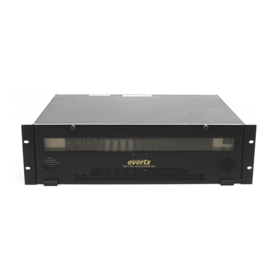
evertz 7700 Series Manual
Debug kit
Hide thumbs
Also See for 7700 Series:
- Manual (164 pages) ,
- Quick start manual (10 pages) ,
- Manual (14 pages)
Table of Contents
Advertisement
Quick Links
1.
Overview.........................................................................................................................................1
2.
Using The Debug Kit....................................................................................................................1
2.1. REMOVING THE MODULE FROM THE FRAME .....................................................................1
2.2. APPLYING POWER TO THE MODULE ...................................................................................2
2.3. UPGRADING THE MODULE FIRMWARE................................................................................3
2.4. RE-INSTALLING THE MODULES ............................................................................................3
Figures
Figure 1: Power Supply Dc Connector ............................................................................................................... 2
Figure 2: Connecting The Power Supply To The Module....................................................................................... 2
TABLE OF CONTENTS
Revision 1.0
7700 Series DTV Frame Manual
7700 Debug Kit
Advertisement
Table of Contents

Related Manuals for evertz 7700 Series


Summary of Contents for evertz 7700 Series
- Page 1 7700 Series DTV Frame Manual 7700 Debug Kit TABLE OF CONTENTS OVERVIEW............................1 USING THE DEBUG KIT........................1 2.1. REMOVING THE MODULE FROM THE FRAME ..............1 2.2. APPLYING POWER TO THE MODULE ...................2 2.3. UPGRADING THE MODULE FIRMWARE................3 2.4. RE-INSTALLING THE MODULES ....................3 Figures Figure 1: Power Supply DC Connector .......................
- Page 2 7700 Series DTV Frame Manual 7700 Debug Kit REVISION HISTORY REVISION DESCRIPTION DATE Original Version August 99 Revision 1.0...
- Page 3 2 amp. Chip Fuses Each 7700 series module is designed to operate as a stand-alone module with its companion I/O module. The power adapter allows you to provide the necessary power to the module to operate it when it is removed from the frame.
- Page 4 7700 Series DTV Frame Manual 7700 Debug Kit 2.2. APPLYING POWER TO THE MODULE The WA-7700DK-PS 7700 Bench power supply provides 12 Volts DC to the module on a standard 4 pin Molex connector. Press the Molex connector onto the power connector on the side of the module. The power connector will either be labeled SFF POWER, or it will have the power designators GND and 12 VDC beside it.
- Page 5 7700 Series DTV Frame Manual 7700 Debug Kit 2.3. UPGRADING THE MODULE FIRMWARE The WA-S76 Serial Upgrade cable is provided to upgrade the firmware on modules that have the 7700 PB circuit board as the base module. See the instructions in the manual chapter Upgrading Firmware in 7700 Modules for complete information on upgrading the module firmware.
- Page 6 7700 Series DTV Frame Manual 7700 Debug Kit This page left intentionally blank 7700DK-4 Revision 1.0...
Need help?
Do you have a question about the 7700 Series and is the answer not in the manual?
Questions and answers