evertz 7700 Series Manual
L-band fiber receiver
Hide thumbs
Also See for 7700 Series:
- Manual (164 pages) ,
- Quick start manual (10 pages) ,
- Manual (30 pages)
Table of Contents
Advertisement
Quick Links
1.
OVERVIEW ....................................................................................................................................... 1
2.
INSTALLATION ................................................................................................................................. 2
2.1. 7708LRA/7708LR-H CONNECTIONS ...................................................................................... 3
2.2. CARE AND HANDLING OF OPTICAL FIBER .......................................................................... 3
2.2.1. Handling and Connecting Fibers .................................................................................... 3
3.
7708LRA/7708LR-H SPECIFICATIONS ............................................................................................ 4
3.1. RF OUTPUT .............................................................................................................................. 4
3.2. OPTICAL INPUT ....................................................................................................................... 4
3.3. ELECTRICAL ............................................................................................................................ 4
3.4. PHYSICAL ................................................................................................................................ 4
4.
STATUS INDICATORS AND DISPLAYS ........................................................................................... 5
4.1. 7708LRA/7708LR-H STATUS INDICATORS ............................................................................ 5
5.
JUMPER POSITIONS ....................................................................................................................... 6
5.1. 7708LRA/7708LR-H JUMPERS ............................................................................................... 6
BY THE GLOBAL FRAME STATUS ......................................................................................... 6
5.3. CONFIGURING THE MODULE FOR FIRMWARE UPGRADES ............................................... 7
5.4. FACTORY AND BDM JUMPERS ............................................................................................. 7
6.
DOT-MATRIX DISPLAY .................................................................................................................... 8
6.1. 7708LRA/7708LR-H CONTROLLED PARAMETERS ............................................................. 10
6.1.1. Adjusting the Optical Power Alarm Thresholds ............................................................ 10
6.1.2. Adjusting the RF Output Power Alarm and Squelch Thresholds .................................. 10
6.1.3. Selecting the Output Gain Mode .................................................................................. 11
6.1.4. Adjusting the RF Output Gain ...................................................................................... 12
6.1.5. Adjusting the AGC Target Level .................................................................................. 12
6.1.6. Enabling/Disabling Squelch Mode ............................................................................... 12
6.1.7. Setting the Card Edge Display Orientation................................................................... 13
6.1.8. Resetting Factory Defaults .......................................................................................... 13
7708LRA and 7708LR-H L-Band Fiber Receiver
TABLE OF CONTENTS
Revision 1.1
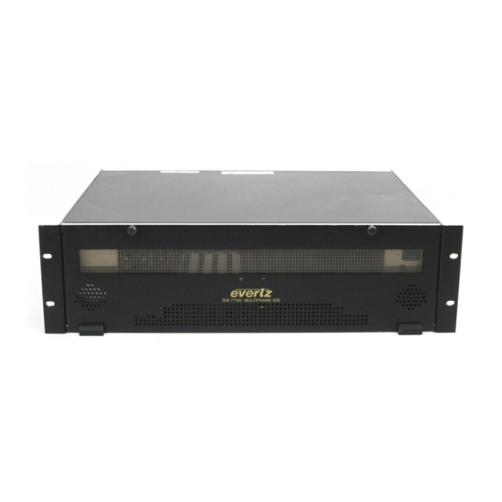
7700 MultiFrame Manual
Advertisement
Table of Contents


Need help?
Do you have a question about the 7700 Series and is the answer not in the manual?
Questions and answers