
Related Manuals for Sony GY-8240UWD


Summary of Contents for Sony GY-8240UWD
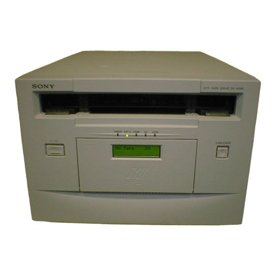
- Page 1 DTF TAPE DRIVE GY-8240UWD GY-8240FC MAINTENANCE MANUAL 1st Edition (Revised 5) Serial No. 10001 and Higher...
- Page 2 Dieses DTF-Bandlaufwerk ist klassifiziert nach LASER KLASSE 1 PRODUKT. Das LASER KLASSE 1 ü PRODUKT-Label befindet sich auf der R ckseite. GY-8240UWD GY-8240FC...
-
Page 3: Table Of Contents
SV-205 Board Replacement ............. 1-25 1-10. Functions of LED Indicators on Circuit Boards ........1-27 1-11. Line Mode ....................1-28 1-11-1. Overview .................. 1-28 1-11-2. Starting/Ending the Line Mode ..........1-29 1-11-3. Switch Function ............... 1-30 1-11-4. Setting Mode ................1-31 GY-8240UWD GY-8240FC... - Page 4 L Cassette Position and S Cassette Position ......3-6 3-2. Upper Drum Assembly Replacement ............3-8 3-3. Drum Assembly Replacement ..............3-14 3-4. Brush Slip Ring Assembly Replacement ..........3-20 3-5. W Cleaner Assembly Cleaning Roller Replacement ........ 3-23 3-6. CTL/TC Head Cleaner Replacement ............3-27 GY-8240UWD GY-8240FC...
- Page 5 4-6. CTL/TC Head Azimuth Adjustment ............4-22 4-7. CTL/TC Head Position Adjustment ............4-25 4-8. Time Code Level Adjustment in Rev Mode ..........4-28 4-9. CONFI Head Height Adjustment .............. 4-31 4-10. Drum Head Height Check ................. 4-34 GY-8240UWD GY-8240FC...
- Page 6 Clear All Logs ................5-63 5-6-4. Upload All Logs ............... 5-63 5-6-5. Upload All Set Value and Logs ..........5-64 5-6-6. FMT CPU ................. 5-64 5-6-7. SYS CPU .................. 5-70 5-6-8. SV CPU LOG Mode ..............5-97 5-6-9. IF-CPU ..................5-99 GY-8240UWD GY-8240FC...
- Page 7 5-14-1. Equipments and Tools Used ........... 5-165 5-14-2. Initializing the NV-RAM ............5-166 5-14-3. Electrical Adjustments After Board Replacements ....5-167 5-14-4. Electrical Adjustments After Switching Regulator Replacement ................5-168 5-14-5. Electrical Adjustments After Mechanical Parts Replacements ................. 5-169 GY-8240UWD GY-8240FC...
- Page 8 7-4. Frame List ....................7-22 7-5. Supplied Accessories List ................. 7-24 7-6. Optional Fixtures List ................7-24 8. Block Diagram and Frame Wiring 8-1. Circuits Descriptions ................... 8-1 8-2. Block Diagram .................... 8-3 8-3. Frame Wiring ....................8-4 GY-8240UWD GY-8240FC...
-
Page 9: Manual Structure
The descriptions in this manual will only mention GY-8240 except where there is a need to differentiate between GY-8240UWD and GY-8240FC. The illustrations in this manual are that of the GY-8240UWD unless specified otherwise. Relative manual Besides this maintenance manual, the following manual is available for the unit. -
Page 10: Trademarks
Trademarks and registered trademarks used in this manual are follows. . Windows is a registered trademark of Microsoft Corporation. . Ethernet is a registered trademark of Xerox Corporation. . IBM PC/AT is registered trademark of International Business Machine, Inc. GY-8240UWD GY-8240FC... -
Page 11: Service Overview
Remove the four screws and remove the front panel. PWH3 x 5 PWH3 x 5 Bottom plate Put the right-side or the left-side of the panel downward. Then remove the eight screws and remove the bottom plate. GY-8240UWD GY-8240FC... -
Page 12: Cassette Compartment Removal/Installation
1. Remove the top panel. (Refer to Section 1-1.) 2. Slide the knobs on the plate MD assembly each inwardly to remove the plate MD assembly. CN930 (Move the knobs outwardly to fix the plate MD assem- bly.) Knob Plate MD assembly Knob Removal Installation GY-8240UWD GY-8240FC... - Page 13 Positioning leg Cassette compartment Flexible card wire/board Positioning hole Harness 9. Connect the harness to the connector (CN930) on the CL-29 board. 10. Reattach the cassette compartment bracket assembly. 11. Reattach the plate MD assembly and the top plate. GY-8240UWD GY-8240FC...
-
Page 14: Main Parts Layout
9 CTL/TC head cleaner @[ Capstan shaft 0 T drawer assembly @] Cleaning roller block !- TG-10 tape guide @\ Pinch press block != Pinch roller @; CONFI head ![ T reel table @' Threading gear block !] T brake assembly GY-8240UWD GY-8240FC... -
Page 15: Printed Circuit Boards Layouts
PTC-99 ......!\ SCS-28 ....... !; SE-533 ....... !' SE-606 ....... !, SV-205 ....... !. TR-119 ....... @/ TR-120 ....... @- Switching regulator ... @= FC-82 ......... !; *1 : For GY-8240UWD *2 : For GY-8240FC Front Rear <Right-side view> GY-8240UWD GY-8240FC... - Page 16 1-3. Main Parts Layout <Top view of mechanical deck> <Top view of cassette compartment> GY-8240UWD GY-8240FC...
-
Page 17: Function Descriptions And Sensors Layouts
1-3. Main Parts Layout 1-3-3. Function Descriptions and Sensors Layouts !/!- <Top view of mechanical deck> Upper Lower !.@/ <Top view of cassette compartment> <Right-side view> GY-8240UWD GY-8240FC... - Page 18 This is a REC inhibit plug detector switch for the large sensor. cassette. @] Cassette-lid sensor This sensor detects the cassette-lid position (open/ closed), by which it is confirmed whether a cassette is in the cassette insert opening or not. GY-8240UWD GY-8240FC...
-
Page 19: Internal Switch Setting
Factory use DSP-90 Board S200 FM-75 board (A side) Ref No. Contents Factory setting 1 to 8 Factory use DSP-90 board (A side) 1 to 8 Factory use Ref No. Contents Factory setting S200 1 to 8 Factory use GY-8240UWD GY-8240FC... -
Page 20: Connector/Cable Information
1-5. Connector/Cable Information 1-5. Connector/Cable Information 3 OPTION 1 : RS-232C (25-pin female) Rear panel (GY-8240UWD) 4 OPTION 2 : RS-232C (25-pin female) < External View > OPTION OPTION-1 OPTION-2 COLLISION OPTION-3 LINK Pin No. Signal POWER AC IN SCSI... - Page 21 → – – – – – ( ) : Pin numbers is the case of 9-PIN [Information] [Information] [Information] [Information] [Information] Cable Connection When connecting PC and GY-8240, connect the each connector refering to the above information. 1-11 GY-8240UWD GY-8240FC...
- Page 22 1-5. Connector/Cable Information 56 SCSI (68-pin female) (GY-8240UWD) < External View > Pin No. Signal Pin No. Signal DB12 (+) DB12 (_) DB13 (+) DB13 (_) DB14 (_) DB14 (+) DB15 (+) DB15 (_) DBP1 (_) DBP1 (+) — —...
- Page 23 1-5. Connector/Cable Information SCSI BUS SIGNAL LINES Host computer GY-8240UWD Data bus (bit 0-15, parity P-P1) Busy (BSY) Select (SEL) Reset (RST) Control/Data (C/D) Input/Output (I/O) Message (MSG) Request (REQ) Acknowledge (ACK) Attention (ATN) The bus driver of this unit is differential type.
-
Page 24: Taking Out The Cassette In Tape Slacking
7. By pulling up the tip of the ME wire, wind the tape into the cassette. 10. Hang the tip of the ME wire on the wire holder of the Bracket (C) M gear bracket (C) and fix it. ME wire Wire holder Gear box assembly 1-14 GY-8240UWD GY-8240FC... -
Page 25: Fixtures And Measuring Equipment For Adjustment
RF alignments 8-960-074-32 Alignment Tape, YR2-1A ————— Tracking adjustments 8-960-074-01 Alignment Tape, YR5-1 ————— SV system check J-7202-060-F Slant Guide Alignment Cassette ————— Slant guide slantness adjustment 9-911-053-00 Thickness Gauge ————— Clearance check 9-919-573-01 Cleaning Liquid ————— Cleaning 1-15 GY-8240UWD GY-8240FC... -
Page 26: Measuring Equipment
It is recommended to use the measuring equipments listed below or the equivalents. Each equipment is available as a standard product. Equipment Model Name Remarks Spectrum Analyzer ADVANTEST with external trigger function R3261A bandwidth: more than 100 MHz Oscilloscope TEKTRONIX 2465B Digital Voltmeter ADVANTEST TR6845 1-16 GY-8240UWD GY-8240FC... -
Page 27: Alignment Tapes
Recording signal (RF) . RF Alignment/Check Test signal Randomize data 200000 . Factory use 220000 230000 240000 250000 (3) YR5-1 (for RF alignment) Part No. : 8-960-074-01 Contents Recording signal (RF) . RF Alignment/Check Test signal Randomize data 90000 1-17 GY-8240UWD GY-8240FC... -
Page 28: Power Block
CN104 PSW4 x 8 Switching CN601 regulator MB-887 board Wire holder Rear panel B3 x 6 10. Install a switching regulator in the reverse order of removal. B3 x 6 B3 x 6 1-18 GY-8240UWD GY-8240FC... -
Page 29: Fan Motor (Power Supply) Replacement
10. Fix the cover with the three mounting screws. unit may not operate normally. PSW3 x 6 Cover Fan harness CN103 Tapping screws Label AIR FLOW Fan motor PSW3 x 30 Fan cover 11. Install the fan motor in the reverse order of removal. 1-19 GY-8240UWD GY-8240FC... -
Page 30: Power Cord
Kingdom: 1 Power cord 250 V 10 A (2.0 m): ! 1-551-631-22 2 Plug holder (Brown): 3-613-640-01 AC inlet If the unit is used in the area except above, please contact your local Sony Sales Office/Service Center. 1-20 GY-8240UWD GY-8240FC... -
Page 31: Replacement Of The Boards
Adjustment does not need after the board replacement. 1-9-8 SV-205 Refer to Section “5-14-3. Electrical Adjustment After Board Replacement”. *1: For GY-8240UWD *2: For GY-8240FC *3: Refer to Section 1-3-2. On the SV-205 and IF-780 boards, ROMs are mounted. When replacing these boards, check the ROM version by the following procedure and update the firmware if necessary. -
Page 32: And Fm-75 Boards Replacement
For installation, perform in the reverse order of the remov- al procedures. After inserting the board, press in the two eject levers simultaneously and connect firmly the board to the connec- tor of the motherboard (MB-887 board). 1-22 GY-8240UWD GY-8240FC... -
Page 33: Board Replacement
Flexible card wire CCM-33 board PWH2.6 x 4 PWH2.6 x 4 Flexible card wire For installation, perform in the reverse order of the remov- al procedures. 1-23 GY-8240UWD GY-8240FC... -
Page 34: Board Replacement
SV-205 board and correct the routing of the harness. For installation, perform in the reverse order of the remov- al procedures. Unless the HN-258 board is not held in the bracket C, open the SV-205 board and correct the routing of the harness. 1-24 GY-8240UWD GY-8240FC... -
Page 35: Board Replacement
6. Remove the seven screws to remove the MD shield plate. SV-205 board BVTT3 x 6 Nylon rivet Screw PWH3 x 5 Flexible card wire F chassis assembly MD shield plate BVTT3 x 6 Nylon rivet PWH3 x 5 1-25 GY-8240UWD GY-8240FC... - Page 36 CN18 CN20 CN27 CN22 CN10 CN15 CN16 CN17 10. Pivot open the SV-205 board about 110-degree and remove it in the arrow direction. SV-205 board For installation, perform in the reverse order of the remov- al procedures. 1-26 GY-8240UWD GY-8240FC...
-
Page 37: Functions Of Led Indicators On Circuit Boards
Lights up when C1 error arises in the last half of the D/H truck. Orange Lights up when C2 error arises in the last half of the truck. FM-75 Board LEDs on the board are all for factory adjustment. 1-27 GY-8240UWD GY-8240FC... -
Page 38: Line Mode
To return from the line mode to the normal operation condition, power this unit off and then on. . In Normal Operation Display IF-CPU FMT-CPU Panel SYS-CPU SV-CPU . In Line Mode Display IF-CPU FMT-CPU Panel SYS-CPU SV-CPU 1-28 GY-8240UWD GY-8240FC... -
Page 39: Starting/Ending The Line Mode
3: Cassette type currently inserted (GY1: DTF-1 GY cassette, GY2: DTF-2 GY cassette, DR2: DIR cassette) 4: Current parity status (27P: 27 parity, 9P:9 parity) 5: Current format status (DTF1: DTF-1 mode, DTF2: DTF-2 mode) Ending the Line Mode Turn the power OFF. 1-29 GY-8240UWD GY-8240FC... -
Page 40: Switch Function
RIGHT Changes the setting value S114 DOWN Changes the setting value and shifts the mode S113 LEFT Changes the setting value S106 UNLOAD Ejects the tape S117 ENTER Exits from the setting mode (Saves the setting value) 1-30 GY-8240UWD GY-8240FC... -
Page 41: Setting Mode
3. To change the setting value, press the specific key listed in the following list. 4. To exit from the setting mode, press the switches below. When storing the setting value: S117 (ENTER) When storing no setting value: S110 (ESC) 1-31 GY-8240UWD GY-8240FC... - Page 42 Former EXIT SS adjusting mode In all status EXIT TRC Tracking adjusting mode In all status EXIT PLM Head mode when playing back When stopping Next Former EXIT C1 mode when recording When stopping Next Former EXIT 1-32 GY-8240UWD GY-8240FC...
-
Page 43: Scsi Control Software Scsitool.exe
In the GY-8240FC, SCSI is adopted as the upper protocol of the FC. By using the FC for the board and cable, the same check can be performed using SCSI commands. 1-12-1. Operating Environment For GY-8240UWD PC : IBM PC/AT compatible... -
Page 44: Starting
4. Select the desired tests such as single commands, etc. 1-12-4. Ending 1. Click “ ” at the top right of the SCSI_TOOL screen, or click “ ”at the top left, select “Close” of the popup menu, and close the screen. 1-34 GY-8240UWD GY-8240FC... -
Page 45: Functions
Indicates which device is connected to which ID. When several devices are connected, the device ID targeted can be changed. How to use : Click the item to be selected with the mouse. <Fig. 2> Scan Function Menu of Device 1-35 GY-8240UWD GY-8240FC... - Page 46 . ADAPTER #0 : Set the adapter number to “0”. . ADAPTER #1 : Set the adapter number to “1”. . TARGET #0 to #7 : Set the SCSI ID of the target to “0” to “7”. 1-36 GY-8240UWD GY-8240FC...
- Page 47 2) DMS_CMD ... Single command issue function for DMS ♦Refer to Fig. 5. <Fig. 5-1> DMS Single Command Menu <Fig. 5-2> When “REQUEST SENSE (03H)” of the Popup Menu is Selected <Fig. 5-3> Screen When “<Fig. 5-2>” is Executed 1-37 GY-8240UWD GY-8240FC...
- Page 48 <Fig. 6-2> Screen When “<Fig. 6-1>” is Executed . SEND VOLUME TAG (B6H) (Single Command Setup Screen) . READ ELEMENT STAT (B8H) . INIT ELM STAT WITH COND (E7H) . COMMAND SET UP — Command parameter setting 1-38 GY-8240UWD GY-8240FC...
- Page 49 . RESERVE UNIT (16H) . RELEASE UNIT (17H) SCSI command . COPY (18H) (For details of functions, refer to “GY-8240UWD PROTOCOL . ERASE (19H) AND COMMAND SPECIFICATIONS” or “GY-8240FC . MODE SENSE (1AH) PROTOCOL AND COMMAND SPECIFICATIONS”.) ...
- Page 50 1-12. SCSI Control Software scsitool.exe <Fig. 7-3> Screen When “<Fig. 7-2>” is Executed (Error) <Fig. 7-4> Screen When “<Fig. 7-2>” is Executed (GOOD) 1-40 GY-8240UWD GY-8240FC...
- Page 51 . WRT VOL LBL CMD SET — Setting of parameters of Write Volume Label command . MT/UNMT CMD SET — Setting of parameters of Mount/Unmount command . EJECT CMD SET — Setting of parameters of Eject command 1-41 GY-8240UWD GY-8240FC...
- Page 52 1-12. SCSI Control Software scsitool.exe <Fig. 8-2> When “WRITE CMD SET” (Write command setup) of the Popup Menu is Selected <Fig. 8-3> Dialog Box When “<Fig. 8-2>” is Executed 1-42 GY-8240UWD GY-8240FC...
- Page 53 . READ POSITION — Displays the Read Position data . LOG SENSE — Displays the Log Sense data . READ VOLUME LABEL — Displays the Read Volume Label data . SET UP — For setting the display format 1-43 GY-8240UWD GY-8240FC...
- Page 54 1-12. SCSI Control Software scsitool.exe <Fig. 9-2> When “CDB PACKET” of the Popup Menu is Selected <Fig. 9-3> Screen When “<Fig. 9-2>” is Executed <Fig. 9-4> When “REQUEST SENSE” of the Popup Menu is Selected 1-44 GY-8240UWD GY-8240FC...
- Page 55 1-12. SCSI Control Software scsitool.exe <Fig. 9-5> Screen When “<Fig. 9-4>” is Executed <Fig. 9-6> When “SET UP” of Popup Menu is Selected <Fig. 9-7> Dialog Box When “<Fig. 9-6>” is Executed 1-45 GY-8240UWD GY-8240FC...
- Page 56 How to use : Click “About...” of the popup menu. The version dialog box will be displayed. [Popup Menu] . About... : SCSI TOOL version <Fig. 10-1> Help Menu (Function which Displays the Tool Version) <Fig. 10-2> Dialog Box When “<Fig. 10-1>” is Executed 1-46 GY-8240UWD GY-8240FC...
-
Page 57: Scsitool-Aging Command
. Vol.Unit Num : The number of volumes to be made on the tape. [Default] 5 . Volume Size : Capacity per volume. (Unit MB) [Default] 500 MB The capacity per volume should be the same. Different values cannot be set. 1-47 GY-8240UWD GY-8240FC... - Page 58 If the SCSI command name and results are OK, outputs “OK”. If bad, details are output. . Bad spot number after writing/reading, etc. As the value of the bad spot number, etc., the value before starting writing/reading and value when writing/reading ended are outputted. . Ending time 1-48 GY-8240UWD GY-8240FC...
- Page 59 VOLUME position check OK !! LOAD/UNLOAD >> OK!! Write Retry Block Num (end) = 0 Read Retry Block Num (end) = 0 Bad Spot Num (end) = 0 Read Retry Num (end) = 0 Finish Time: 18:08:13 1-49 GY-8240UWD GY-8240FC...
- Page 60 To change the parameter, perform “1. Parameter Settings”. Any type of cassette can be used. Load the cassette before starting aging. 2. Execution To execute, click “START” in Fig. 11-3 Operates according to “3. Operating Sequence” <Fig. 11-3> Screen Selected 1-50 GY-8240UWD GY-8240FC...
- Page 61 Repeat number of settings ↓ Rewind ↓ Read ↓ Verify ↓ Space ↓ Repeat number of settings ↓ Check and save the bad spot number, etc. after writing/reading ↓ Move volume ↓ Next page Check volume position 1-51 GY-8240UWD GY-8240FC...
- Page 62 >> ERROR!! <SENSE-KEY [ 0] - ASC [ 0] - ASCQ [ 0]> EOM bit ON Example 2: In this case, the details are output and the process is stopped. WRITE >> ERROR!! <SENSE-KEY [ 5] - ASC [20] - ASCQ [00]> INVALID COMMAND 1-52 GY-8240UWD GY-8240FC...
-
Page 63: General Function Check Using The Scsi Control Function
To connect the FC, the EZ-SCSI software (Adaptec) must be installed. 2. GY-8240UWD/FC (with terminator) 3. SCSI cable (P-cable for differential) (for GY-8240UWD)/FC cable (for GY-8240FC) 4. DTF-2 cassette (L or S cassette) 5. The floppy disk containing “Scsichk.exe” and the test Script. - Page 64 11. The cassette is automatically ejected after the test is completed. (It takes for approximately 15 minutes to complete the test.) 9. Verification and termination 1. Confirm there is no “mismatch” error during execution. 2. Click the “ ” to the upper right of Scsichk to close. 1-54 GY-8240UWD GY-8240FC...
- Page 65 Recover . Read (FM error) . Rewind . Read (10 block) . Unmount . Read (10 block) . Recover . Read (FM error) . Mount . Read (10 block) . Read (10 block) . Read (FM error) 1-55 GY-8240UWD GY-8240FC...
- Page 66 . Read (FM error) . Read (10 block) . Read (FM error) . Read (10 block) . Read (10 block) . Read (FM error) . Read (10 block) . Read (10 block) . Read (FM error) Unload . Unload 1-56 GY-8240UWD GY-8240FC...
-
Page 67: Revision Label
Revision Label Firmware Hardware REVISION GZ1.00XX A Model Name GY ..GY-2120 series GZ ..GY-8240UWD series GF ..GY-8240FC series DM ..DMS-B9 series GZ1.00 B Revision No. of the Firmware/Hardware (Total version number of the unit) C Firmware Destination XX : XX-Capable model (example : GZ1.00 AB) -
Page 68: Revision Label For Board
CT-205 board (A side) DPR-160 board (A side) FM-75 board (A side) SCS-28 board (A side) *1 FC-82 board (A side) *2 IF-780 board (A side) *1 For GY-8240UWD *2 For GY-8240FC DSP-90 board (A side) SV-205 board (B side) 1-58 GY-8240UWD... -
Page 69: Update Of The Firmware
(For example, copying the data from the ftp sever via a network.) 2. Start the Tera Term. 3. Enter “UPDATE” in the starting display of this unit to enter the UPDATE mode. (As for UPDATE mode, refer to Section 5-5.) 1-59 GY-8240UWD GY-8240FC... - Page 70 DSP CPU → SV1 CPU → SV2 CPU → SYS CPU → IF CPU → FMT CPU After the update|is completed, this unit will be reactivated. Confirming 7. Enter “ rom” in the PC and press the ENTER key. The display below appears. Check that the firmware revision and ROM version are updated. 1-60 GY-8240UWD GY-8240FC...
-
Page 71: Update With Dtf-2 Cassette
9. Select “ROM Version” in the Rom menu:2 by using “9” and “0” button, then press the ENTER button. The ROM version of the CPU is displayed on the LCD. Check the ROM version of every CPU using the “9” and “0” button. ROM version FMT [XX.XX.XX] 1-61 GY-8240UWD GY-8240FC... -
Page 72: Update With The Network (Ftp)
“550 [file name] No such file or directory.” Use the correct file name. The files are log_all and rom_all only. “500 user not found.” Use the correct user. The user is only “sony”, addition and change are not permitted. 1-62 GY-8240UWD GY-8240FC... -
Page 73: Update Using Psc
2. Select [Test] on the menu of PSC → [Firmware Download], then “Firmware Download” window is displayed. 3. Select the radio button of “Drive” in the Download Device, then enters the updating mode of drive. Updated screen of PSC 1-63 GY-8240UWD GY-8240FC... - Page 74 “OK” button. Then perform the updating again. If this updates operate without performing the power supply reset, the updating screen may freeze. Error message of unsuccessful updating 1-64 GY-8240UWD GY-8240FC...
-
Page 75: General Information Of Device Connection
GY-8240FC, FC switch and then host computer. 2. When GY-8240FC and host computer’s connection is established, and then perform to turn GY- 8240FC off/on, there is probability that unable to re-establish the connection between host computer and GY-8240FC. 1-65 GY-8240UWD GY-8240FC... -
Page 77: Periodic Maintenance And Inspection
*1: Accumulated hours when the power of the unit is on. *2: Accumulated hours when the drum rotates in the threading end state. *3: A definition of threading operation is as follow: Unthreading end state → Threading end state → Unthreading end state → ... GY-8240UWD GY-8240FC... -
Page 78: Periodic Check List
3 : The life of these parts may be shortened depending on the operating condition of this unit or the operating environment. GY-8240UWD GY-8240FC... - Page 79 Use new CL ARM ASSY and new CL GUIDE RAIL (or former CL ARM ASSY and former CL GUIDE RAIL). Don’t use the former one and the new one. The color of the parts shows the part is former or new. GY-8240UWD GY-8240FC...
-
Page 80: Cleaning
2. Preparation (1) Turn the power off and remove the power cord. (2) Remove the top panel. (Refer to Section 1-1.) (3) Remove the plate MD. (Refer to Section 1-2.) (4) Remove the cassette compartment. (Refer to Section 1-2.) GY-8240UWD GY-8240FC... -
Page 81: Tape Running Surface Of Upper Drum And Rotary Heads Cleaning
This may damage the rotary heads and the brush/slipring assembly. 3. After cleaning, wipe it with a dry cleaning cloth two or three times. Rotary heads Cleaning cloth Upper Drum’s Tape Running Surface and Rotary Heads Cleaning GY-8240UWD GY-8240FC... -
Page 82: Tape Running Surface Of Lower Drum And Lead Surface Cleaning
3. After cleaning, wipe it with a dry cleaning cloth two or three times. Drum lead surface Skewer Lower drum’s running surface Cleaning cloth Lower Drum’s Tape Running Surface and Lead Surface Cleaning GY-8240UWD GY-8240FC... -
Page 83: Stationary Heads Cleaning
Remove the magnetic powder completely during cleaning. 2. After cleaning, wipe it with a dry cleaning cloth two or three times. CTL/TC head CTL/TC erase head Confidence head Full erase head Stationary Heads Cleaning GY-8240UWD GY-8240FC... -
Page 84: Tape Running System And Tape Cleaner Cleaning
3. After cleaning, clean it with a dry cleaning cloth two or three times. Capstan TG-3 (Exit guide) TG-9 TG-7 TG-8(T-TEN) TG-6 TG-10 TG-0 Slant guide Tape cleaner TG-2 TG-4 (Entrance guide) TG-1 (S-TEN) TG-5 Pinch roller Tape Running System and Tape Cleaner Cleaning GY-8240UWD GY-8240FC... -
Page 85: Cassette Compartment And Cassette Supports Cleaning
Do not apply an excessive force to the compartment block. 4. Clean the cassette supports on the mechanical deck using a dry cloth (or gauze). 5. Reattach the cassette compartment. (Refer to Section 1-2.) Cassette supports Compartment block Cassette supports Cassette compartment block assembly Stationary Heads Cleaning GY-8240UWD GY-8240FC... -
Page 87: Replacement Of Mechanical Parts
About the amount that will remain on the tip of a stick of 2 mm in diameter, as shown in the figure. . Do not use the grease and oil except for specified portions. 3. Stop Washer Do not reuse the removed stop washer. . Stop washer (d = 2.3 mm): 3-669-596-00 GY-8240UWD GY-8240FC... -
Page 88: Index
CTL/TC Head Assembly Gear Box Assembly/Threading Motor 3-19 Pinch Roller Threading Ring 3-20 Pinch Press Assembly 3-10 S Tension Regulator Assembly 3-21 Capstan Motor 3-11 T Tension Regulator Assembly 3-22 Reel Table Assembly 3-12 T Drawer Assembly 3-23 GY-8240UWD GY-8240FC... - Page 89 3-1. General Information for Parts Replacement <Overall Block> Part Name Section Cassete Compartment Motor 3-24 Part Name Section Fan Motor (Rear Panel) 3-25 Fan Motor (Power Supply) 1-8-2 GY-8240UWD GY-8240FC...
-
Page 90: Threading End Mode And Unthreading End Mode
TG-3 (Exit guide) TG-6 TG-8 (T tension regulator) M gear TG-7 TG-9 TG-5 CONFI head Pinch roller TG-4 (Threading roller) Tape cleaner Capstan TG-2 TG-10 Slant guide TG-1 (S tension regulator) TG-0 Full erase head Threading End Mode GY-8240UWD GY-8240FC... - Page 91 TG-3 (Exit guide) TG-8 (T tension regulator) M gear TG-9 TG-7 CONFI head TG-6 Capstan TG-0 Tape cleaner Full erase head TG-2 Pinch roller Slant guide TG-10 TG-1 (S tension regulator) TG-5 TG-4 (Threading roller) Unthreading End Mode GY-8240UWD GY-8240FC...
-
Page 92: L Cassette Position And S Cassette Position
Method 2: 1. Remove the SE-606 board. (Refer to Section 3-14.) 2. Turn fully the gear of reel shift motor in the arrow C direction. S reel table T reel table L cassette REC INHIBIT sensor Gear L Cassette Position GY-8240UWD GY-8240FC... - Page 93 Method 2: 1. Remove the SE-606 board. (Refer to Section 3-14.) 2. Turn fully the gear of reel shift motor in the arrow D direction. S reel table T reel table L cassette REC INHIBIT sensor Gear S Cassette Position GY-8240UWD GY-8240FC...
-
Page 94: Upper Drum Assembly Replacement
21. Meantime, turn the power off. 22. ATF Circuit Operation Check (4: ATF operation check) (Refer to Section 5-9-7.) 23. SAT Circuit Operation Check (5: SAT operation check) (Refer to Section 5-9-8.) 24. Resetting the Drum Run-1 Hours Meter (Refer to Section 5-4-8.) GY-8240UWD GY-8240FC... - Page 95 1. Removing the W Cleaner Assembly Remove the W cleaner assembly. (Refer to steps 1 and 2 in Section 3-5.) 2. Removing the Brush Slip Ring Assembly Remove the brush slip ring assembly. (Refer to steps 1 and 2 in Section 3-4.) GY-8240UWD GY-8240FC...
- Page 96 If the hexagon screw of the upper drum remover is being rotated with the four upper drum fixing screws loosen insufficiently, the lower drum may get damaged. Upper drum remover Remove the Upper Drum Assembly 3-10 GY-8240UWD GY-8240FC...
- Page 97 Do avoid applying cleaning fluid to the contacting points and patterns. . Contacting points of upper drum . Patterns of upper drum . Contacting points of lower drum Patterns . Patterns of lower drum (Wipe with a dry cleaning cloth) Cleaning 3-11 GY-8240UWD GY-8240FC...
- Page 98 Tightening torque : 39.2 x 10 Install the Upper Drum Assembly {4.0 kgf.cm} (6) Tighten securely the four screws in the same order in step (5) using a torque screwdriver. Tightening torque : 58.8 x 10 {6.0 kgf.cm} 3-12 GY-8240UWD GY-8240FC...
- Page 99 (3: Auto PG adjust) 16. Performing the Playback System All Automatic Adjustment (DTF-2) Refer to Section 5-15-1. (RF01: RF PB all adjustment (DTF-2)) 17. Saving the RF System Adjust Data Refer to Section 5-15-3. (RF07: RF data save) 3-13 GY-8240UWD GY-8240FC...
-
Page 100: Drum Assembly Replacement
24. ATF Circuit Operation Check (4 : ATF operation check) (Refer to Section 5-9-7.) 25. SAT Circuit Operation Check (5 : SAT operation check) (Refer to Section 5-9-8.) 26. Resetting the Drum Run-1 Hours Meter (Refer to Section 5-4-8.) 3-14 GY-8240UWD GY-8240FC... - Page 101 1. Turn the power off and remove the power cord. 2. Remove the top panel. (Refer to Section 1-1.) 3. Remove the plate MD. (Refer to Section 1-2.) 4. Remove the cassette compartment. (Refer to Section 1-2.) 3-15 GY-8240UWD GY-8240FC...
- Page 102 (5). Drum harnesses According the drum assembly can be re- moved. Remove the Drum Assembly Be careful not to touch the CTL/TC head and peripheral tape guides when removing the drum assembly. 3-16 GY-8240UWD GY-8240FC...
- Page 103 After cleaning, wipe with a dry cleaning cloth. Fixing screw (Cleaning) Positioning hole (Cleaning) Fixing screw (Cleaning) . MD base assembly Positioning pin (Cleaning) Screw hole (Cleaning) Screw hole (Cleaning) Positioning pin Screw hole (Cleaning) (Cleaning) Cleaning 3-17 GY-8240UWD GY-8240FC...
- Page 104 (Refer to Section 2-2-2.) Tightening torque : 78.4 x 10 N.m {8 kgf.cm} (2) Lower drum’s tape running surface and lead surface. (Refer to Section 2-2-3.) Install the Drum Assembly After cleaning, wipe with a dry cleaning cloth. 3-18 GY-8240UWD GY-8240FC...
- Page 105 (RF01: RF PB all adjustment (DTF-2)) 19. Saving the RF System Adjust Data Refer to Section 5-15-3. (RF07: RF data save) 20. Performing the Record System All Automatic Adjustment (DTF-2) Refer to Section 5-15-2. (RF05: RF REC all adjustment (DTF-2)) 3-19 GY-8240UWD GY-8240FC...
-
Page 106: Brush Slip Ring Assembly Replacement
1. Turn the power off and remove the power cord. 2. Remove the top panel. (Refer to Section 1-1.) 3. Remove the plate MD. (Refer to Section 1-2.) 4. Remove the cassette compartment. (Refer to Section 1-2.) 3-20 GY-8240UWD GY-8240FC... - Page 107 341 board contacting points with a dry cleaning cloth. Do not apply cleaning fluid to the contacting points. Contacting point Contacting point (Wipe with a dry (Wipe with a dry cleaning cloth) cleaning cloth) Cleaning 3-21 GY-8240UWD GY-8240FC...
- Page 108 Never apply excessive force to the cover. 5. Connecting the Flexible Card Wire Connect the flexible card wire into connector CN2 on the HN-258 board. Tightening torque : 14.7 x 10 N.m {1.5 kgf.cm} Install the Brush/Slip Ring Assembly 3-22 GY-8240UWD GY-8240FC...
-
Page 109: W Cleaner Assembly Cleaning Roller Replacement
1. Turn the power off and remove the power code. 2. Remove the top panel. (Refer to Section 1-1.) 3. Remove the plate MD. (Refer to Section 1-2.) 4. Remove the cassette compartment. (Refer to Section 1-2.) 3-23 GY-8240UWD GY-8240FC... - Page 110 Replace the Cleaning Roller (2) Align the two pins of the W cleaner assembly with the two holes of the drum support. (3) Tighten the screw while moving the W cleaner assembly in the direction of arrow A. 3-24 GY-8240UWD GY-8240FC...
- Page 111 (5) Repeat steps (2) to (4) until specifications 1 B > 0.4 mm Spec.2: and 2 are satisfied. . When the specifications are not satisfied: Portion A (Supporting point) Portion B Roller arm assembly Cleaning Roller Position Adjustment 3-25 GY-8240UWD GY-8240FC...
- Page 112 7. Confirming the Cleaning Solenoid Harness W cleaner assembly Operation Sensor holder Full erase head Refer to Section 5-4-13. (CH05: Pinch Roller and Cleaning Roller Sole- Install the Harness noid Check) 8. Resetting Cleaning-1 (Cleaning Roller Count-1) Refer to Section 5-4-8. 3-26 GY-8240UWD GY-8240FC...
-
Page 113: Ctl/Tc Head Cleaner Replacement
1. Turn the power off and remove the power cord. 2. Remove the top panel. (Refer to Section 1-1.) 3. Remove the plate MD. (Refer to Section 1-2.) 4. Remove the cassette compartment. (Refer to Section 1-2.) 3-27 GY-8240UWD GY-8240FC... - Page 114 CL arm assembly. (2) Fix the CL arm assembly by a new stop washer. Stop washer (2.3): 3-669-596-00 Groove Remove/Install the CL Arm Assembly 3-28 GY-8240UWD GY-8240FC...
- Page 115 CH01: Threading Motor Check, and confirm that the CL arm assem- bly smoothly operates while repeating the CL arm assembly threading and unthreading. M gear CL guide rail Confirm the CL Arm Assembly Operation 3-29 GY-8240UWD GY-8240FC...
-
Page 116: Confi Head Assembly Replacement
Remove the CL guide rail. Refer to step 5 in Section 3-20. 2. Disconnecting the Flexible Card Wire Disconnect the flexible card wire from the connector CN2 on the CT-205 board. CONFI head assembly Disconnect the Flexible Card Wire 3-30 GY-8240UWD GY-8240FC... - Page 117 (Refer to Section 2-2-4.) Adjustment after replacement 8. Adjusting the CONFI Head Height 10. Confirming the Time Code Level Refer to Section 4-9. in REV Mode Refer to Section 4-8. 9. Confirming the Tape Running Refer to Section 4-3. 3-31 GY-8240UWD GY-8240FC...
-
Page 118: Ctl/Tc Head Replacement
1. Turn the power off and remove the power cord. 2. Remove the top panel. (Refer to Section 1-1.) 3. Remove the plate MD. (Refer to Section 1-2.) 4. Remove the cassette compartment. (Refer to Section 1-2.) 3-32 GY-8240UWD GY-8240FC... - Page 119 Remove the screw, then remove the CTL/TC head assembly from the MD base assembly. Be careful not to touch the drum (especially rotary heads). Also, take care not to damage the peripheral tape guides. Remove the CTL/TC Head Assembly 3-33 GY-8240UWD GY-8240FC...
- Page 120 Install the CL guide rail. (Refer to step 24 in Section 3-20.) 11. Cleaning Clean the CTL/TC head and CONFI head surfac- es with a cleaning cloth moistened with cleaning fluid. After cleaning, wipe with a dry cleaning cloth. 3-34 GY-8240UWD GY-8240FC...
- Page 121 Refer to Section 5-9-6. (3: Auto PG Adjust) 19. Confirming the Tracking Refer to Section 4-4. 20. Confirming the Tape Running Refer to Section 4-3. 21. Confirming the Time Code Level in REV Mode Refer to Section 4-8. 3-35 GY-8240UWD GY-8240FC...
-
Page 122: Pinch Roller Replacement
1. Turn the power off and remove the power cord. 2. Remove the top panel. (Refer to Section 1-1.) 3. Remove the plate MD. (Refer to Section 1-2.) 4. Remove the cassette compartment. (Refer to Section 1-2.) 3-36 GY-8240UWD GY-8240FC... - Page 123 (2) Fix the pinch arm assembly by a new stop washer. Stop washer (2.3): 3-660-596-00 (3) Push the pinch arm assembly manually in the direction of the drum, then release. At that time, confirm that the pinch arm assembly smoothly returns to the former position. 3-37 GY-8240UWD GY-8240FC...
- Page 124 Clean the pinch roller and TG-5 guide surfaces Diameter Thickness Part No. with a cleaning cloth moistened with cleaning 0.13 mm 3-701-439-01 fluid. 3.0 mm (Refer to Section 2-2-5.) 0.25 mm 3-701-439-11 Adjust the Pinch Arm Assembly Vertical Play 3-38 GY-8240UWD GY-8240FC...
-
Page 125: Pinch Press Assembly Replacement
(2) Disconnect the harnesses from the four connectors CN216, CN231, CN232 and CN233 on the HN-268 board. 2. Removing the Pinch Press Assembly Remove the screw, then remove the pinch press assembly from the unit. Remove the Pinch Press Assembly 3-39 GY-8240UWD GY-8240FC... - Page 126 Install the Pinch Press Assembly Adjustment after Replacement 6. Confirming the Pinch Solenoid Operation Refer to Section 5-4-13. (CH05: Pinch Roller and Cleaning Roller Sole- noid Check) Spec.1: A = 0.3 to 0.5 mm Confirming the Pinch Press Clearance 3-40 GY-8240UWD GY-8240FC...
-
Page 127: Capstan Motor Replacement
4. Remove the cassette compartment. (Refer to Section 1-2.) 5. Remove the front panel. (Refer to Section 1-1.) 6. Remove the DPR-160 board. (Refer to Section 1-9-2.) 7. Remove the FM-75 board. (Refer to Section 1-9-2.) 8. Remove the bottom plate. (Refer to Section 1-1.) 3-41 GY-8240UWD GY-8240FC... - Page 128 Capstan motor board the hole of the MD base assembly. (2) Connect the harness disconnected in (1) of Harness step 4 to the connector of the capstan motor Remove/Install the Capstan Motor board. 3-42 GY-8240UWD GY-8240FC...
- Page 129 12. Performing the CONFI Head Height Refer to Section 4-9. 13. Performing the Servo Adjustment Refer to Section 5-9-5. (All Motors, Tension Sensors Adj) 14. Confirming the Capstan Motor Operation Refer to Section 5-4-13. (CH06: Capstan Motor Check) 3-43 GY-8240UWD GY-8240FC...
-
Page 130: Reel Table Assembly Replacement And Adjustment
1. Turn the power off and remove the power cord. 2. Remove the top panel. (Refer to Section 1-1.) 3. Remove the plate MD. (Refer to Section 1-2.) 4. Remove the cassette compartment. (Refer to Section 1-2.) 3-44 GY-8240UWD GY-8240FC... - Page 131 3. Confirming the Reel Table Height Refer to Section 3-12-2. 4. Confirming the Reel Brake Clearance Refer to Section 3-12-3. S reel brake 5. Confirming the Reel Brake Release T reel brake Amount Refer to Section 3-12-4. Install the Reel Table Assembly 3-45 GY-8240UWD GY-8240FC...
-
Page 132: Reel Table Height Adjustment
(2) Check that the specification is satisfied while rotating the supply reel table counter-clock- wise by one turn. If the specification is not satisfied, perform steps 8 and 9. 3-46 GY-8240UWD GY-8240FC... - Page 133 0.5 mm 3-701-441-21 tighten the two set screws. Reel Table Height Adjustment 12. Rechecking the Reel Table Height Refer to steps 3 through 7. 13. Installing the SE-606 Board Install the SE-606 board. (Refer to Section 3-14.) 3-47 GY-8240UWD GY-8240FC...
-
Page 134: Reel Brake Clearance Check
(Refer to Section 3-13.) Brake arm block Boss Spec. : A = Clearance exists. Brake arm block S reel table Brake arm block Boss Spec. : A = Clearance exists. Brake arm block Reel Brake Clearance Check 3-48 GY-8240UWD GY-8240FC... -
Page 135: Reel Brake Release Amount Confirmation
(Specification 1) If the specification 1 is not satisfied, perform step 3 and higher. Spec.1: The brake lining doesn’t touch a reel table while reel table rotating. Reel Brake Release Amount Check 3-49 GY-8240UWD GY-8240FC... - Page 136 Confirm the brake release amount meets the (Solenoid energized position) specification. (Refer to step 5 of this section.) Remove the Reel Motor Plate Assembly 7. Installing the Reel Motor Plate Assembly Install the reel motor plate assembly. (Refer to Section 3-14.) 3-50 GY-8240UWD GY-8240FC...
-
Page 137: Brake Lining Replacement
(2) Hook the spring to the reel motor plate assembly. Adjustment after Replacement Reel motor plate assembly 3. Confirming the Reel Brake Clearance Refer to Section 3-12-3. Remove/Install the Brake Lining 4. Confirming the Reel Brake Release Amount Refer to Section 3-12-4. 3-51 GY-8240UWD GY-8240FC... -
Page 138: Reel Motor Plate Assembly Replacement
12. Confirming the Reel Brake Release Amount (Refer to Section 3-12-4.) 13. Performing the Servo Adjustment (Refer to Section 5-9-5.) (All Motors, Tension Sensors Adj) 14. Confirming the Reel Motor Operation (CH07: S, T Reel Motor Check) (Refer to Section 5-4-13.) 3-52 GY-8240UWD GY-8240FC... - Page 139 (1) Press the three claws in the arrow directions SE-606 board to remove the SE-606 board. (2) Disconnect the flexible card wire from the connector CN1 on the SE-606 broad. Flexible card wire Claw Claws Disconnect the Flat Cable of the SE-606 Board 3-53 GY-8240UWD GY-8240FC...
- Page 140 The reel motor plate assembly cannot be removed in the S or T cassette position. (3) Remove the screw to remove the shaft holder. Gear Reel motor plate assembly Notch Guide Plate holder assembly Remove the Shaft Holder 3-54 GY-8240UWD GY-8240FC...
- Page 141 5. Connecting the Flexible Card Wire Connect the flexible card wire disconnected in step 4 to a reel motor board of a new reel motor Motor holder assembly plate assembly. Slide shaft Remove the Reel Motor Plate Assembly 3-55 GY-8240UWD GY-8240FC...
- Page 142 (3) Hang the tip of the ME wire on the wire Wire holder Lug terminal ME wire holder of attachment fitting (C) and fix it. T drawer assembly Plate holder (T) assembly Install the ME Wire 3-56 GY-8240UWD GY-8240FC...
- Page 143 12. Confirming the Reel Brake Release Amount Refer to Section 3-12-4. 13. Performing Servo Adjustment Refer to Section 5-9-5. (All Motors, Tension Sensors Adj) 14. Confirming the Reel Motor Operation Refer to Section 5-4-13. (CH07: S, T Reel Motor Check) 3-57 GY-8240UWD GY-8240FC...
-
Page 144: Reel Shift Motor Replacement
PWH3 x 8 Assembly Remove the reel motor plate assembly. (Refer to steps 1 to 4 in Section 3-14.) PA guard 2. Removing the PA Guard Remove the screw to remove the PA guard. Removing the PA Guard 3-58 GY-8240UWD GY-8240FC... - Page 145 Install the reel motor plate assembly. (Refer to steps 5 to 10 in Section 3-14.) Adjustment after replacement 7. Confirming the Reel Shift Motor Operation (CH02: Reel Shift Motor Check) Refer to Section 5-4-13. Installing the PA Guard 3-59 GY-8240UWD GY-8240FC...
-
Page 146: Reel Shift Gear Replacement
(Refer to steps 1 to 4 in Section 3-14.) 2. Removing the PA Guard Remove the PA guard. (Refer to step 2 in Section 3-15.) 3. Removing the Motor Holder Assembly Remove the motor holder assembly. (Refer to step 3 in Section 3-15.) 3-60 GY-8240UWD GY-8240FC... - Page 147 10. Installing the Reel Motor Plate Assembly Install the reel motor plate assembly. (Refer to steps 5 to 10 in Section 3-14.) Adjustment after Replacement 11. Confirming the Reel Shift Motor Operation (CH02: Reel shift Motor Check) (Refer to Section 5-4-13.) 3-61 GY-8240UWD GY-8240FC...
-
Page 148: Tape Guide Replacement
T tension regulator assembly Refer to Section 3-22. TG-9 Ring assembly Refer to Section 3-20. TG-10 T drawer assembly Refer to Section 3-23-1. Refer to “3-23-2. Slant Guide Slantness Adjustment” Slant guide Refer to “4-3. Tape Running Adjustment” Refer to “4-4. Tracking Adjustment” 3-62 GY-8240UWD GY-8240FC... -
Page 149: Tape Cleaner Replacement
Tape cleaner from the S plate assembly. S plate assembly Installation 2. Installing the Tape Cleaner Tighten the screw while moving a new tape cleaner clockwise. Tightening torque: 19.6 x 10 N.m {2 kgf.cm} Remove/Install the Tape Cleaner 3-63 GY-8240UWD GY-8240FC... -
Page 150: Gear Box Assembly Replacement
1. Turn the power off and remove the power cord. 2. Remove the top panel. (Refer to Section 1-1.) 3. Remove the plate MD. (Refer to Section 1-2.) 4. Remove the cassette compartment. (Refer to Section 1-2.) 3-64 GY-8240UWD GY-8240FC... - Page 151 Release the harnesses from the bundling band (B) Gear box assembly and disconnect the harnesses from the connectors CN233 CN920 of the CCM-15 board and CN904 of the PTC-54 board. Bundling band (A) HN-268 board Remove the Gear Box Assembly 3-65 GY-8240UWD GY-8240FC...
- Page 152 Avoid contacting the harness to the drive portion Positioning hole (A) of the gear box assembly. Positioning hole (B) Installing the Gearbox Assembly Adjustment after Replacement 7. Confirming the Threading Motor Operation Refer to Section 5-4-13. (CH01: Threading Motor Check) 3-66 GY-8240UWD GY-8240FC...
-
Page 153: Threading Ring Assembly Replacement
Use the new CL Arm Assembly and the new CL Guide Rail (or the former CL Arm Assembly and the former CL Guide Rail). Don’t use the former one and the new one. The color of the parts shows the part is former or new. 3-67 GY-8240UWD GY-8240FC... - Page 154 Harness 4. Removing the W Cleaner Assembly Remove the W cleaner assembly. (Refer to steps 1 and 2 in Section 3-5.) HN-258 board Flexible card wire Flexible card wire Disconnect the Flexible Card Wire and the Harness 3-68 GY-8240UWD GY-8240FC...
- Page 155 Remove the T Drawer Assembly. (Refer to steps 1 and 2 in Section 3-23-1.) 10. Removing the Gear Box Assembly Remove the gearbox assembly. (Refer to steps 1 to 3 in Section 3-19.) Remove the S Plate Assembly 3-69 GY-8240UWD GY-8240FC...
- Page 156 Refer to steps 4 to 6 in Section 3-19. 17. Confirming the Threading Ring Operation Turn the M gear of the gear box assembly manually and confirm that the threading ring and the three ring rollers rotate smoothly while repeating the threading and unthreading. 3-70 GY-8240UWD GY-8240FC...
- Page 157 24. Installing the CL Guide Rail Install the CL guide rail with two screws. 25. Confirming the CL Arm Assembly Operation Confirm the CL arm assembly operation. (Refer to step 3 in Section 3-6.) Install the CL Guide Rail 3-71 GY-8240UWD GY-8240FC...
- Page 158 Refer to step 5 in Section 3-10. (CH01: Threading Motor Check) Refer to Section 5-4-13. 33. Confirming the Tape Running Refer to Section 4-3. 31. Confirming the Cleaning Solenoid Operation (CH05: Pinch Roller and Cleaning Roller Sole- noid Check) Refer to Section 5-4-13. 3-72 GY-8240UWD GY-8240FC...
-
Page 159: S Tension Regulator Assembly Replacement
2. Turn the power off and remove the power cord. 3. Remove the top panel. (Refer to Section 1-1.) 4. Remove the plate MD. (Refer to Section 1-2.) 5. Remove the cassette compartment. (Refer to Section 1-2.) 3-73 GY-8240UWD GY-8240FC... - Page 160 Adjustment after Replacement 3. Performing the Servo Adjustment Refer to Section 5-9-5. (All Motors, Tension Sensors Adj) 4. Adjusting the Tape Running Cleaning Refer to Section 4-3. Installing the S Tension Regulator Assembly 3-74 GY-8240UWD GY-8240FC...
-
Page 161: T Tension Regulator Assembly Replacement
2. Turn the power off and remove the power cord. 3. Remove the top panel. (Refer to Section 1-1.) 4. Remove the plate MD. (Refer to Section 1-2.) 5. Remove the cassette compartment. (Refer to Section 1-2.) 3-75 GY-8240UWD GY-8240FC... - Page 162 (2) Tighten the two screws to fix the T tension regulator assembly. (3) Connect the harness to the connector CN207 of the TR-120 board. CN207 TR-120 board Positioning hole Positioning hole Install the T Tension Regulator Assembly 3-76 GY-8240UWD GY-8240FC...
- Page 163 Threading ring assembly T Tension Regulator Assembly Operation Adjustment after Replacement 4. Performing the Servo Adjustment Refer to Section 5-9-5. (All Motors, Tension Sensors Adj) 5. Performing the Tape Running Refer to Section 4-3. 3-77 GY-8240UWD GY-8240FC...
-
Page 164: T Drawer Assembly Replacement And Adjustment
2. Turn the power off and remove the power cord. 3. Remove the top panel. (Refer to Section 1-1.) 4. Remove the plate MD. (Refer to Section 1-2.) 5. Remove the cassette compartment. (Refer to Section 1-2.) 3-78 GY-8240UWD GY-8240FC... - Page 165 T drawer assembly (2) Release the harness from the hook of the T Tape top drawer assembly. sensor board (3) Remove the two screws to remove the T drawer assembly. Hook Removing the T Drawer Assembly 3-79 GY-8240UWD GY-8240FC...
- Page 166 (3) Connect the harness to the connector of the tape top sensor board. (4) Hang the harness on the hook of the T drawer assembly to fasten. Hook Installing the T Drawer Assembly 3-80 GY-8240UWD GY-8240FC...
- Page 167 T reel table rotates smoothly. (3) After confirmation, hang the tip of the ME wire on the wire holder of the bracket (C) to fasten. Brake assembly Confirming the ME Wire Operation 3-81 GY-8240UWD GY-8240FC...
- Page 168 T drawer assembly returns smoothly. Surface B Roller Threading ring Spec.2: At the unthreading state, the lower surface of the roller does not touch with the surface B of the threading ring. Confirm the T Drawer Assembly Operation 3-82 GY-8240UWD GY-8240FC...
- Page 169 0.2 mm or less * When the specification 3 and 4 are not satisfied. . Poly-slider washer for adjustment Diameter Thickness Part No. 0.13 mm 3-701-439-01 3.0 mm 0.25 mm 3-701-439-11 0.5 mm 3-701-439-21 T Drawer Arm Height Adjustment 3-83 GY-8240UWD GY-8240FC...
- Page 170 (4) and later again. Portion D T drawer arm T drawer assembly Spec.5: 0.2 mm (Between arm stopper and arm) T Drawer Arm Height Adjustment Adjustment after Replacement 7. Adjusting the Slant Guide Slantness Refer to Section 3-23-2. 3-84 GY-8240UWD GY-8240FC...
-
Page 171: Slant Guide Slantness Adjustment
Tools . Cassette reference plate (L)(MW-088): J-6320-880-A . Tension regulator slantness check tool (BW-080): J-6190-800-A . Thickness gauge: 9-911-053-00 . Cleaning cloth: 3-184-527-01 . Cleaning fluid: 9-919-573-01 . Locking compound: 7-432-114-11 . Slant Guide Alignment Cassette: J-7202-060-F 3-85 GY-8240UWD GY-8240FC... - Page 172 Remove the tension regulator slantness check tool and cassette reference plate (L). 4. Cleaning Clean the slant guide with a cleaning piece moistened with cleaning fluid. Spec.2: 0.15 mm < B < 0.25 mm Slant Guide Slantness Check 3-86 GY-8240UWD GY-8240FC...
- Page 173 Tape (5) Perform step (2) again and confirm specifica- tion 3 is satisfied. Lower flange Drafting tape Spec. 3: The drafting tapes and the tape do not touch. Yellow label Tape Running Check at the T Reel 3-87 GY-8240UWD GY-8240FC...
- Page 174 (3) Check again that the tape running condition Adjusting Slant Guide Slantness satisfies specification 3. If specification 3 is not satisfied, repeat steps 6 and 7. (4) Apply the locking compound to the adjust- ment screw. 3-88 GY-8240UWD GY-8240FC...
-
Page 175: Cassette Compartment Motor Replacement
4. Remove the cassette compartment assembly. (Refer to Section 1-2.) Tools . L wrench (Across flat has 0.89 mm): 7-700-736-06 . Grease (SGL-601): 7-651-000-10 . Cleaning cloth: 3-184-527-01 . Cleaning fluid: 9-919-573-01 . Calipers (or the equivalent) 3-89 GY-8240UWD GY-8240FC... - Page 176 Motor joint 5. Removing the Spacer and Disconnecting the Harness (1) Remove the spacer. Spacer Harnesses (2) Unsolder and disconnect the harness from the motor. Cassette compartment motor Remove the Cassette Compartment Motor (2) 3-90 GY-8240UWD GY-8240FC...
- Page 177 Motor joint when the motor joint is pushed toward the motor, and tighten the set screw. Tightening torque: 60 x 10 {6 kgf.cm} Press Motor joint Cassette compartment motor Spec.: 3.8 mm 4.2 mm Attach the Motor Joint 3-91 GY-8240UWD GY-8240FC...
- Page 178 Worm (grease smearing) board. Attach the Cassette Compartment Motor Adjustment after Replacement 12. Checking the Cassette Compartment Motor Operation Refer to Section 5-4-13. (CH03: Cassette Compartment Motor Check.) Perform this check with the cassette compartment installed in the unit. 3-92 GY-8240UWD GY-8240FC...
-
Page 179: Fan Motor Rear Panel Replacement
(2) Release the harness from the harness clamper. 2. Removing the Rear Panel Remove the eight screws and open the rear panel in the arrow direction. Harness clamper Rear panel B3 x 6 B3 x 6 B3 x 6 Remove the Rear Panel 3-93 GY-8240UWD GY-8240FC... - Page 180 6. Connecting the Harness Rear panel (1) Connect the harness to the connector CN601 of the MB-887 board. (2) Fasten the harness in the harness clamper. B3 x 6 B3 x 6 B3 x 6 Install the Rear Panel 3-94 GY-8240UWD GY-8240FC...
-
Page 181: Tape Path Alignment
When setting the cassette or the alignment tape on the VTR, put it to the cassette supports on the mechan- ical deck. And then, put a weight on the cassette so that it does not rise up. The weight about 1000 g is suitable. Cassette lid Lock knob GY-8240UWD GY-8240FC... -
Page 182: Preparation
It is illustrated in the threading end mode. “ TG ” in the figure means the tape guide. TG-3 (Exit guide) TG-6 CTL/TC erase head TG-7 CTL/TC head TG-8 (T tension regulator) TG-9 TG-5 Confi head Capstan Drum Pinch roller TG-4 (Threading roller) TG-1 (S tension regulator) Slant guide TG-0 TG-10 Full-erase head TG-2 GY-8240UWD GY-8240FC... -
Page 183: Locking Compound
When loosening the following screws, apply the locking compound to the screws after adjustment is completed. The locking compound that applied to other surrounding parts must be wiped off using gauze or soft cloth. . Locking compound : 7-432-114-11 CTL/TC head assembly T drawer assembly (Slant guide) S tension regulator assembly GY-8240UWD GY-8240FC... -
Page 184: Ctl/Tc Head Zenith Adjustment
(1). CTL/TC head If the specification is not satisfied, perform steps 3 and later. If it is satisfied, perform step 7. Flatness plate Spec.: A = No clearance. B = No clearance. CTL/TC Head Zenith Check GY-8240UWD GY-8240FC... - Page 185 CONFI head with a cleaning cloth moistened with cleaning fluid. Flatness Zenith adjustment screw CTL/TC head plate . Removal/Installation of the CL guide rail B3 x 8 B3 x 8 CL guide rail CTL/TC Head Zenith Adjustment GY-8240UWD GY-8240FC...
-
Page 186: Tape Running Adjustment
The tape curl is less than 1/10 of the tape width. specification 1. Lead of drum entrance side The tape runs without any curl at the lead. If specification 1 is not satisfied, perform steps 5 and 6. Tape Running Check at Drum Entrance Side GY-8240UWD GY-8240FC... - Page 187 6. Recheck the Tape Running at Drum Entrance Side Refer to step 4. If the specification 1 is not satisfied, perform the adjustment in step 5 again. TG-1 Height adjustment nut TG-0 TG-2 Tape Running Adjustment at Drum Entrance Side GY-8240UWD GY-8240FC...
- Page 188 If specification 2 is not satisfied, perform steps 7 and 8. (c) VAR _ _ _ _ _ 5 times normal speed mode Check that the tape running condition satisfies specification 2. If specification 2 is not satisfied, perform steps 6, 7 and 8. GY-8240UWD GY-8240FC...
- Page 189 The tape runs in contact with the upper flange. The tape curl is less than 1/10 of the tape width. TG-4(Threading roller) The tape runs without any curl at the upper and lower flanges. Tape Running Check at Drum Exit Side GY-8240UWD GY-8240FC...
- Page 190 (If the specification 2 is not satisfied in VAR _1 time normal speed mode and VAR _5 times normal mode, perform the adjustment in step 7 again.) 9. Adjust the Slant Guide Slantness Adjust the slantness of the slant guide so that specification 3 is satisfied. 4-10 GY-8240UWD GY-8240FC...
- Page 191 B3 x 12 Adjustment plate . TG-4 height adjustment (only when the specification is not satisfied in REV x 10 mode and VAR x _1/30 mode) <Unthreading end mode> TG-4 (Threading roller) Tape Running Adjustment at Drum Exit Side 4-11 GY-8240UWD GY-8240FC...
-
Page 192: Tracking Adjustment
<DPR-160 board, side A> TRIG: TP401/DPR-160 board (REC AE SEL) 3. Set the Alignment Tape Set the YR2-1A and put a weight (about 1000 g) on the cassette so that it does not rise up. TP603 TP401 Preparation 4-12 GY-8240UWD GY-8240FC... - Page 193 (on the drum entrance or exit side) in steps 7 and later. (5) Press the switch S110 (ESC) on the DSP-90 board twice to exit the tracking adjustment mode. - To be continued. - 4-13 GY-8240UWD GY-8240FC...
- Page 194 The tape curl is less than 1/10 of the tape If the specification 6 is not satisfied, adjust width. the height of TG-1 and TG-2. Tracking Check (VAR_ _ _ _ _ 1 → → → → → FWD) 4-14 GY-8240UWD GY-8240FC...
- Page 195 - To be continued. - 100 % (=RF max x 0.8) 80 to 95 % Marker If the pressure against the tape at TG-1 and 2 are too much, the waveform becomes as shown in the right figure. (NG) <Fig.2> Marker 4-15 GY-8240UWD GY-8240FC...
- Page 196 2 Perform the tracking adjustment again. (Refer to step (1) through (7) mentioned above.) (8) Press the switch S110 (ESC) on the DSP-90 board twice to exit the tracking adjustment mode. 8. Recheck the Tracking Refer to steps 5 through 6. 4-16 GY-8240UWD GY-8240FC...
- Page 197 - To be continued. - 3 < B < 1 <Fig. 2> Maker If the pressure against the tape at TG-3 is too much, the waveform becomes as shown in the right figure. (In this case, it is NG) 4-17 GY-8240UWD GY-8240FC...
- Page 198 11. Recheck the Tracking Refer to step 5. 12. Install the CL Guide Rail Install the CL guide rail with two screws. (Refer to Step 24 in Section 3-20.) 4-18 GY-8240UWD GY-8240FC...
-
Page 199: Ctl/Tc Head Height Adjustment
TRIG: TP401/DPR-106 board (REC AE SEL) <CT-205 board, side A> TP600 3. Set the Alignment Tape Set the YR2-1A and put a weight (about 1000 g) on the cassette so that it does not rise up. <DPR-160 board, side A> TP401 Preparation 4-19 GY-8240UWD GY-8240FC... - Page 200 B of the tape is pushed up. <CTL Output waveform> If the level increases, perform step 8. A > 5 V p-p Spec. : The level decreases when pressing down and pushing up the alignment tape. CTL/TC Head Height Check 4-20 GY-8240UWD GY-8240FC...
- Page 201 Refer to Section 4-7. 12. Check the CTL/TC Head Height Refer to steps 6 and 7 in this section. maximize 13. Check the CTL/TC Head Azimuth Refer to Section 4-6. <Fig. 2> Height adjustment screw maximize CTL/TC Head Height Adjustment 4-21 GY-8240UWD GY-8240FC...
-
Page 202: Ctl/Tc Head Azimuth Adjustment
CH-2: TP16/FM-75 board (R-SYNC signal) <FM-75 board, side A> 3. Set the Alignment Tape Set the YR2-1A and put a weight (about 1000 g) on the cassette so that it does not rise up. TP11 TP16 Preparation 4-22 GY-8240UWD GY-8240FC... - Page 203 CTL signal and falling edge of R SYNC signal satisfies the specification. If the specification is not satisfied, perform steps 8 and later. CTL/TC head PB CTL (TP11/FM-75) R-SYNC (TP16/FM-75) Spec. : A = 5 ±50 us CTL/TC Head Azimuth Check 4-23 GY-8240UWD GY-8240FC...
- Page 204 Portion B Portion A Azimuth adjustment screw 11. Check the CTL/TC Head Azimuth Refer to steps 6 and 7 in this section. PB CTL (TP11/FM-75) R-SYNC (TP16/FM-75) Spec. : A = 5 ±50 us CTL/TC Head Azimuth Adjustment 4-24 GY-8240UWD GY-8240FC...
-
Page 205: Ctl/Tc Head Position Adjustment
<DPR-160 board, side A> 3. Set the Alignment Tape Set the YR2-1A and put a weight (about 1000 g) on the cassette so that it does not rise up. TP603 TP401 <FM-75 board, side A> TP15 Preparation 4-25 GY-8240UWD GY-8240FC... - Page 206 If the specification is not satisfied, perform steps 8 and later. TC-26 (TP15/FM-75) Spec. : When the tracking control volume is fixed, the output level in the center portion of the RF envelope waveform is maximum. CTL/TC Head Position Check 4-26 GY-8240UWD GY-8240FC...
- Page 207 14. Check the CTL/TC Head Height Refer to Section 4-5. 15. Check the CTL/TC Head Azimuth CTL/TC Head Position Adjustment Refer to Section 4-6. 16. Check the CTL/TC Head Position Refer to steps 6 and 7 in this section. 4-27 GY-8240UWD GY-8240FC...
-
Page 208: Time Code Level Adjustment In Rev Mode
CH-1: TP608/CT-205 board (TC ANA signal) <CT-205 board, side A> 3. Set the Alignment Tape TP608 Set the YR2-1A and put a weight (about 1000 g) on the cassette so that it does not rise up. Preparation 4-28 GY-8240UWD GY-8240FC... - Page 209 9. Check the Time Code Output Level Check that the time code output level B satisfies Time Code Level Check in REV Mode specification 1. If the specification 1 is not satisfied, perform steps 10 and later. 4-29 GY-8240UWD GY-8240FC...
- Page 210 The tape runs in contact with the upper flange. The tape curl is less than 1/10 of the tape width. TG-4 (Threading roller) The tape runs without any curl at the lower flange. Time Code Level Adjustment in REV Mode 4-30 GY-8240UWD GY-8240FC...
-
Page 211: Confi Head Height Adjustment
TRIG: TP401/DPR-106 board (REC AE SEL) <CT-205 board, side A> TP609 3. Set the Alignment Tape Set the YR2-1A and put a weight (about 1000 g) on the cassette so that it does not rise up. <DPR-160 board, side A> TP401 Preparation 4-31 GY-8240UWD GY-8240FC... - Page 212 C or D of the tape shown in the figure and pushing up the alignment tape. is slightly pushed. Watch portion E of the waveform. The level CONFI Head Height Check change will appear in the portion. If the level increases, perform step 11. 4-32 GY-8240UWD GY-8240FC...
- Page 213 (4) Tighten the two head fixing screws. Tightening torque : 19.6 x 10 {20 kgf.cm} (5) Check the CONFI head height again. Refer to step 7 of this section. maximize CONFI Head-to-tape Contact Adjustment 4-33 GY-8240UWD GY-8240FC...
-
Page 214: Drum Head Height Check
<DPR-160 board, side A> TRIG: TP401/DPR-160 board (REC AE SEL) 3. Set the Alignment Tape Set the YR2-1A and put a weight (about 1000 g) on the cassette so that it does not rise up. TP803 TP603 TP401 Preparation 4-34 GY-8240UWD GY-8240FC... - Page 215 Perform this check after replacing the upper drum assembly, when the specification is not satisfied, reinstall the upper drum assembly. (Refer to Section 3-2.) (4) Press the switch S110 (ESC) on the DSP-90 board twice to exit the tracking adjustment mode. 4-35 GY-8240UWD GY-8240FC...
-
Page 217: Maintenance Mode
The maintenance mode of the GY-8240 can be used by entering commands from the terminal of a personal computer (referred to as PC hereafter) connected to the RS-232C connector of the option-1 port, or from the PC/workstation connected to the network port (Ethernet/10BASE-T). "means ENTER key in this section. GY-8240UWD GY-8240FC... -
Page 218: Equipments Required And Connection
Ethernet port) of the PC and to perform terminal emulation equivalent to VT100. The freeware “Tera Term (Pro)” is recommended. Network cable (Crossed) Network port OPTION-3 GY-8240 work station AC IN To other GY-8240 Network port OPTION-3 Network cable (Straight) GY-8240 work station GY-8240UWD GY-8240FC... - Page 219 For the network port, after starting the GY-8240, connect by Telnet, and enter the HELP command to check the connection. Example of the start screen 1 Example of the start screen 2 Hello, I am GY-8240. DTF tape drive. ============================== GY-8240UWD GY-8240FC...
-
Page 220: List Of Menu Configurations
This mode is used to set the RS-232C baud rate etc. Activation: Enter “SERV"”. Termination: Enter “QUIT"”. Automatic adjustment mode (For more details, refer to Section 5-9.) This mode is used to adjust the drive. Activation: Enter “ADJ"”. Termination: Enter “QUIT"”. GY-8240UWD GY-8240FC... - Page 221 HELP : Display this menu | LOG : Log display mode : ROM version display | SERV : Operation mode set mode : Adjustment mode | SETUP : Setup mode +======================================[ Copyright(c) 2000 Sony Corp. ]===+ HELP Command Execution Screen GY-8240UWD GY-8240FC...
-
Page 222: Command Description
Vendor information display Serial number set Serial number display help : Display help quit : Quit . SERV - - - - - Service information set (operation mode set mode) 2 : Service information display Default service information set GY-8240UWD GY-8240FC... - Page 223 . Adjust mode 51, 53, 54, 55, 56 and 58 are not usable. Refer to Section 5-15 as to adjustment of RF system. (For firmware revision 1.34 or higher, adjust modes 51, 53, 54, 55, 56, and 58 are not dis- played.) . 1 through 5 of adjust mode are usable. GY-8240UWD GY-8240FC...
-
Page 224: Custom Mode
Display Help Menu | 1 : Vendor information set 2 : Vendor information display | 3 : Serial number set 4 : Serial number display ]===+ +======================================[ Copyright(c) 2000 Sony Corp. CUSTOM=> Display Help Menu Execution Screen GY-8240UWD GY-8240FC... -
Page 225: Vendor Information Set
=>12" Series (0:GY-10/1:GY-2120/2:GY-8240/3:DIR-240/4:DIR-120/5:EVALUATOR) =>3" Are you sure? (Y:yes/N:no)=>Y" CUSTOM=> Vendor Information Setting Screen Default value of each item . Vender ID: . Vender name: SONY . Vender ROM version: 1.00 . Machine name: GY-8240 . Interface: . Series: GY-8240UWD GY-8240FC... -
Page 226: Vendor Information Display
Entering “Y"” sets the setting and writes it in the memory area for storage (NVRAM). Entering “N"” does not change the setting. CUSTOM=>3" *****[ SERIAL NUMBER SET ]************************* Serial number [00000000] => 00010080" Are you sure?(Y:yes/N:no)=> y" CUSTOM=> Serial Number Set Execution Screen 5-10 GY-8240UWD GY-8240FC... -
Page 227: Serial Number Display
5-3. CUSTOM Mode 5-3-6. Serial Number Display Function: Displays the serial number. Operation: Enter “4"”. CUSTOM=>4" *****[ SERIAL NUMBER DISPLAY ]********************* Serial number [00010080 ] CUSTOM=> Serial Number Display Execution Screen 5-11 GY-8240UWD GY-8240FC... -
Page 228: Diag Mode
6: Hours meter clear | 7: Maintenance value display 8: Maintenance value set | 11: FMT CPU 12: SYS CPU 13: SV CPU 14: IF CPU 15: DSP CPU +======================================[ Copyright(c) 2000 Sony Corp. ]===+ DIAG=> Display Help Menu Execution Screen 5-12... -
Page 229: All Check
| IF(S2) | OFF | OFF | OFF | OFF | OFF | OFF | OFF | OFF | +---------+-----+-----+-----+-----+-----+-----+-----+-----+ | DSP(S2) | OFF | OFF | OFF | OFF | OFF | OFF | OFF | OFF | +---------+-----+-----+-----+-----+-----+-----+-----+-----+ DIAG=> Dip Switch Display Execution Screen 5-13 GY-8240UWD GY-8240FC... -
Page 230: Rom Version Display
XX.XX.XX [ISP] XX.XX.XX DIAG=> ROM Version Display Execution Screen 5-4-6. Serial Number Display Function: Displays the serial number. Operation: Enter “4"”. DIAG=> 4" *****[ SERIAL NUMBER DISPLAY ]********************* Serial number [00000000] DIAG=> Serial Number Display Execution Screen 5-14 GY-8240UWD GY-8240FC... -
Page 231: Hours Meter Display
Cleaning: Total times of operations by the cleaning roller. The number cannot be reset. Cleaning-1: Times of operations by the cleaning roller. Meter for periodic maintenance of the GY-8240. The number can be reset at the GY-8240. 5-15 GY-8240UWD GY-8240FC... -
Page 232: Hours Meter Clear
Hours Meter Clear Execution Screen 5-4-9. Maintenance Value Display Function: Displays the maintenance time setting. Operation: Enter “7"”. DIAG=> 7" *****[ MAINTENANCE VALUE DISPLAY ]********************* Cleaning (hours) [50] Maintenance-1 (hours) [1000] DIAG=> Maintenance Value Display Execution Screen 5-16 GY-8240UWD GY-8240FC... -
Page 233: Maintenance Value Set
. Cleaning hours: . Maintenance-1 hours: 1000 5-4-11. FMT CPU Function: Entes the DIAG mode of the FMT CPU. Operation: Enter “11"”. After selecting this item, the DIAG menu of the FMT CPU will be automatically displayed. 5-17 GY-8240UWD GY-8240FC... - Page 234 | 12:PCI RAM Check | 13:ROM Check | 14:RAM Check | 15:DMA Check | 16:Bank Memory Check Copyright (c) 2000, SONY Corp. | +--------------------------------------------------------------------------+ FMT_DIAG => FMT CPU Execution Screen 1. Quit tool Function: Exits the DIAG mode of the FMT CPU.
-
Page 235: Sys Cpu
Operation: Enter “all"”. 4. ROM RAM Compare (SYS CPU) Function: Compares the firmware in the ROM area and one extended in the RAM. When they do not coincide with each other, errors are displayed. Operation: Enter “31"”. 5-19 GY-8240UWD GY-8240FC... - Page 236 Loop back test (with CRC) in the EQ block Function: Performs the loop back test (with the CRC error correction code) to including the EQ block. If some error occurs, it will be caused by failures of the DPR or FM board. Operation: Enter “6"”. 5-20 GY-8240UWD GY-8240FC...
-
Page 237: Sv Cpu
CH06 Capstan motor check CH07 S reel, T reel motor check CH08 Drum motor check Displays SV adjustment data * Be sure to turn the power off and then on after performing DIAG operations of the servo. 5-21 GY-8240UWD GY-8240FC... - Page 238 MENU Function: Displays the menu list. Operation: Enter “MENU"”. The menu list will be displayed as below. SV1_DIAG=>MENU" -----SVMenu----- R0:SensorOff R1:Sensor1(Bot,Eot,Dew,Th,Rs) R2:Sensor2(Cc) R3:Sensor3(Hole) R4:ServoLocks CH00:REW/REV/FWD/FF/STILL CH01:Threading CH02:ReelPositioning CH03:CassetteCompartment CH04:--reserved-- CH05:CleaningRoller,PinchRoller CH06:Capstan CH07:Reel&Brake CH08:Drum AD:AdjustData Q:ExitToIf ':':TopMenu SV1_DIAG=> 5-22 GY-8240UWD GY-8240FC...
- Page 239 5-4. DIAG Mode b. R0-Sensor Display off Function: Stops sensor information display. Operation: Entering “R0"” displays the following. Entering the R1, R2, or R3 command stops the sensor information display. SV1_TOP=>R0" [TTop-][TEnd-][Dew-][Unth-][Thre*][SftL*][SftS-] 0000 0000 0000 5-23 GY-8240UWD GY-8240FC...
- Page 240 After checking, wipe the dew sensor completely dry of water. After wiping completely, turn on the power again. If the above fails: . Check the sensor. . Check the sensor harness. . Check the sensor input port of the CPU on the SV-205 board. 5-24 GY-8240UWD GY-8240FC...
- Page 241 5-4. DIAG Mode Dew sensor Tape end sensor Tape top sensor (Top view) Sensor Layout 5-25 GY-8240UWD GY-8240FC...
- Page 242 3 When the Cassette Size sensor is pressed, the display changes from “[LSize-]” to “[LSize*]”. (3) To end, enter “ : ”. If the above fails: . Check the corresponding sensor on the PC-70 board. . Check the sensor input port of the CPU on the SV-205 board. 5-26 GY-8240UWD GY-8240FC...
- Page 243 Cassette in switch 2 [Cassette size sensor] [Cassette in sensor (L)] [Cassette in sensor (R)] Position of Cassette Compartment Switches Rear Front Cassette in sensor (L) Cassette size sensor Cassette in sensor (R) Top View of Cassette Compartment 5-27 GY-8240UWD GY-8240FC...
- Page 244 . Check the corresponding sensor on the PTC-59 board. . Check the sensor input port of the CPU on the SV-205 board. When the REC Inhibit sensors S and L fail . Check the corresponding sensor on the SV-205 board. 5-28 GY-8240UWD GY-8240FC...
- Page 245 7 S cassette REC inhibit switch Sensor Sensor 1 Cassette ID-1 sensor 2 Cassette ID-2 sensor 3 1 2 3 Cassette ID-3 sensor 4 Cassette ID-4 sensor 5 Cassette ID-5 sensor 6 Cassette ID-6 sensor Positions of Sensor Switches 5-29 GY-8240UWD GY-8240FC...
- Page 246 The display changes from [Drum-] to [Drum*] when the drum is locked. [CtlValid*]: The display changes from [CtlValid-] to [CtlValid*] when CTL is detected normally. [AtValid*]: The display changes from [AtValid-] to [AtValid*] when the ATF signal is detected normally. 5-30 GY-8240UWD GY-8240FC...
- Page 247 4 Check that when the L key is pressed, the pinch solenoid is turned OFF and the tape runs at high speed in the forward direction. 5 Check that when the “ ; ” key is pressed, the tape stops. (3) To end, enter “ : ”. If the above fails: . Execute DIAG ALL CHECK. 5-31 GY-8240UWD GY-8240FC...
- Page 248 . Check the threading motor. If the threading state and sensor display do not match . Check the Thread End sensor/Unthread End sensor (TR-119 board). . Check the sensor input port of the CPU on the SV-205 board. 5-32 GY-8240UWD GY-8240FC...
- Page 249 5-4. DIAG Mode Threading motor Thread end sensor Threading ring Unthread end sensor <Top view> 5-33 GY-8240UWD GY-8240FC...
- Page 250 . Check the reel shift motor. If the reel table position and sensor display do not match . Check the S position sensor and L position sensor (SV-205 board). . Check the sensor input port of the CPU on the SV-205 board. 5-34 GY-8240UWD GY-8240FC...
- Page 251 5-4. DIAG Mode S reel table T reel table Reel shift motor L position sensor S position sensor <Top view> 5-35 GY-8240UWD GY-8240FC...
- Page 252 “UpEnd” → “Vertical” → “Horizon” → “DownEnd”. For some cassette compartments, pressing the K key may change the sensor state in the order of “UpEnd” → ”Horizon” → ”Vertical” → ”DownEnd” → ”Horizon”, but it is not a malfunction. 5-36 GY-8240UWD GY-8240FC...
- Page 253 . Check the Cassette down sensor (CL-29 board). . Check the sensor input port of the CPU on the SV-205 board. Rear Upper Cassette down sensor (1) Lower Cassette down sensor (2) Cassette compartment motor Front Top View of Cassette Compartment 5-37 GY-8240UWD GY-8240FC...
- Page 254 Moving the compartment manually The compartment moves up and down when the yellow pulley shown in the figure is rotated. To move up, rotate the yellow pulley in the clockwise direction. Cassette compartment Yellow pulley Cassette compartment Down motor 5-38 GY-8240UWD GY-8240FC...
- Page 255 . Check mechanical faults. . Check the cleaning roller solenoid drive circuit (HN-268 board). . Check the cleaning solenoid. When the pinch roller does not function . Check the pinch solenoid circuit (HN-268 board). . Check the pinch solenoid. 5-39 GY-8240UWD GY-8240FC...
- Page 256 5-4. DIAG Mode Pinch lever Cleaning solenoid Pinch solenoid Pinch roller Cleaning roller <Top view> 5-40 GY-8240UWD GY-8240FC...
- Page 257 2 Check that when the K key is pressed, the capstan runs in the forward direction at constant speed. (3) To end the check, enter “ : ”. When the above fail: . Check the capstan motor drive circuit (SV-205 board). . Check the capstan FG output. . Check the capstan motor FG amplifier circuit. 5-41 GY-8240UWD GY-8240FC...
- Page 258 5 Check that when the “ ; ” key is pressed, the T reel stops and the T reel brake is set. 6 Check that when the L key is entered, after the reel brake is released, the T reel rotates in the clock- wise direction at constant speed. 5-42 GY-8240UWD GY-8240FC...
- Page 259 . Check the output from the T reel FG sensor. . Check the T reel FG amplifier circuit (SV-205 board). When the operations of the T reel brake are faulty . Check the T reel brake solenoid. 5-43 GY-8240UWD GY-8240FC...
- Page 260 . Check the drum motor drive circuit (SV-205 board). . Check the drum motor. . Check the drum FG output and drum PG output. . Check the drum FG amplifier circuit (SV-205 board). . Check the drum PG amplifier circuit (SV-205 board). 5-44 GY-8240UWD GY-8240FC...
- Page 261 The Value marked with “*” is fixed or not used. Thread: Fixed value STension: S tension sensor TTension: T tension sensor CapOffst: Capstan offset (Fixed value) CapQpl: For capstan IC NoConne: Not used PgCoarse: PG rough adjustment value PgFine: PG fine adjustment value 5-45 GY-8240UWD GY-8240FC...
-
Page 262: If Cpu
| << STATUS >> << CHECK >> | 11: ROM version 21: Memory check | 12: Dip switch +======================================[ Copyright(c) 2000 Sony Corp. ]===+ IF_DIAG=> IF CPU Execution Screen 1. Quit Tool Function: Exits the DIAG mode of the IF CPU. - Page 263 Display Help menu | 1: All check | << STATUS >> << CHECK >> | 11: ROM version 21: Memory check | 12: Dip switch +======================================[ Copyright(c) 2000 Sony Corp. ]===+ IF_DIAG=> Display Help Menu Execution Screen 5-47 GY-8240UWD GY-8240FC...
- Page 264 IF All check ***** OK(Error Code 00000000) IF_DIAG=> All Check (IF CPU) Execution Screen 4. ROM Version (IF CPU) Function: Displays the IF firmware version. Operation: Enter “11"”. IF_DIAG=>11" ***[ ROM VERSION DISPLAY(IF) ]*** Ver00.55.53 IF_DIAG=> ROM Version (IF CPU) Execution Screen 5-48 GY-8240UWD GY-8240FC...
- Page 265 If errors occur, “ERROR” will be displayed. (For details, refer to “5-13-7. List of Self-Diagnosis Results Codes and Countermeasures”.) IF_DIAG=>21" << IF CPU Memory check >> IF Memory check ***** OK(Error Code 00000000) IF_DIAG=> Memory Check (IF CPU) Execution Screen 5-49 GY-8240UWD GY-8240FC...
-
Page 266: Dsp Cpu
24: Buzzer check 25: Telefile check 26: Telefile power on 27: Telefile power off 28: Telefile all block dump +======================================[ Copyright(c) 2000 Sony Corp. ]===+ DSP_DIAG=> DSP CPU Execution Screen 1. Quit Tool Function: Exits the DIAG mode of the DSP CPU. - Page 267 25: Telefile check 26: Telefile power on 27: Telefile power off 28: Telefile all block dump +======================================[ Copyright(c) 2000 Sony Corp. ]===+ DSP_DIAG=> Display Help Menu Execution Screen 3. All Check (DSP CPU) Function: Executes all automatically practicable checks of DSP check items.
- Page 268 “Finish” will be displayed when the check completes. (For details of an error, refer to “5-13-7. List of Self-Diagnosis Results Codes and Countermeasures”.) DSP_DIAG=>21" << DSP CPU LED check >> DSP LED check ***** Finish(Error Code 00000000) DSP_DIAG=> LED Check (DSP CPU) Execution Screen 5-52 GY-8240UWD GY-8240FC...
- Page 269 “Finish” will be displayed when the check completes. (For details of an error, refer to “5-13-7. List of Self-Diagnosis Results Codes and Countermeasures”.) DSP_DIAG=>23" << DSP CPU LCD check >> DSP LCD check ***** Finish(Error Code 00000000) DSP_DIAG=> LCD Check (DSP CPU) Execution Screen 5-53 GY-8240UWD GY-8240FC...
- Page 270 When operations end normally, “OK” will be displayed. If it ends in an error, “NG” will be displayed. (For details, refer to “5-13-7. List of Self-Diagnosis Results Codes and Countermeasures”.) DSP_DIAG=>26" Telefile Power ON ... OK [DSP Retry Cnt: 0000] DSP_DIAG=> 5-54 GY-8240UWD GY-8240FC...
- Page 271 62 | 3e 3f 40 41 42 43 44 45 46 47 48 49 4a 4b 4c 4d 63 | 3f 40 41 42 43 44 45 46 47 48 49 4a 4b 4c 4d 4e Telefile Power OFF ... OK [DSP Retry Cnt: 0000] DSP_DIAG=> 5-55 GY-8240UWD GY-8240FC...
-
Page 272: Update Mode
UPDATE=> help" +===[ Firmware update mode menu ]=========================================+ | quit : Quit tool help : Display Help menu | 1: From maintenance port 2: From tape +======================================[ Copyright(c) 2000 Sony Corp. ]===+ UPDATE=> Display Help Menu Execution Screen 5-56 GY-8240UWD GY-8240FC... -
Page 273: Help2
+===[ Firmware update mode menu2 ]========================================+ | quit: Quit Tool help: Display Help Menu | 1: From maintenance port 2: From tape | 13: SV CPU 14: IF CPU 15: DSP CPU +======================================[ Copyright(c) 2000 Sony Corp. ]===+ UPDATE=> 5-57 GY-8240UWD GY-8240FC... -
Page 274: From Maintenance Port
<< Firmware update from maintenance port >> Firmware update ready..OK Sending firmware data...Done. Programing Start... From Maintenance Port Execution Screen UPDATE=> 1" << Firmware update from maintenance port >> Firmware update ready..NG UPDATE=> When the Unit Cannot Update 5-58 GY-8240UWD GY-8240FC... -
Page 275: From Tape
If the result is “NG”, it means that the unit cannot be updated, and the UPDATE prompt will be displayed again. UPDATE=> 2" << Firmware update from tape >> Firmware update sure?(Y:yes/N:no)=> y" Firmware update ready..OK Insert tape From Tape Download Execution Screen 5-59 GY-8240UWD GY-8240FC... -
Page 276: Sv Cpu
Be noted that the firmware data format is not the same to one used under “1: From maintenance port”, or “2: From tape” of the update menu. UPDATE=> 13" << SV-CPU download >> << SV1 >> Loading application..............Done. Loading loader..Done. Checking...OK Programming................Done. Done << SV2 >> Loading application............Done. Loading loader..Done. Checking...OK Programming................Done. Done UPDATE=> 5-60 GY-8240UWD GY-8240FC... -
Page 277: If Cpu
Be noted that the firmware data format is not the same to one used under “1: From maintenance port”, or “2: From tape” of the update menu. UPDATE=> 14" << IF-CPU download >> Loading application.............Done.Done. Checking...OK Erasing...Done. Programming........Done. Verifying...OK Done. Done UPDATE=> 5-61 GY-8240UWD GY-8240FC... -
Page 278: Dsp Cpu
Be noted that the firmware data format is not the same to one used under “1: From maintenance port”, or “2: From tape” of the update menu. UPDATE=> 15" << DSP-CPU download >> Loading application....Done. Loading loader..Done. Checking...OK Programming.........Done. Done UPDATE=> 5-62 GY-8240UWD GY-8240FC... -
Page 279: Log Mode
| clear: Clear all log upload : Upload all logs | adsp : Upload all set values and logs | 11: FMT-CPU 12: SYS-CPU 13: SV-CPU 14: IF-CPU +======================================[ Copyright(c) 2000 Sony Corp. ]===+ LOG=> Display Help Menu Execution Screen 5-6-3. Clear All Logs Function: Erases the log contents of all CPUs. -
Page 280: Upload All Set Value And Logs
| 9: IF Cmd Log 10: DISPLAY Log | 12: Register Dump at Exception | 97: Bus Error Counter 98: Media Error Counter Copyright (c) 2000 SONY Corp.| +--------------------------------------------------------------------------* LOG => FMT CPU Execution Screen 1. Quit Tool Function: Exits the LOG mode of the FMT CPU, and returns to the LOG mode of the maintenance mode. - Page 281 Number of boots TIME: System RTC (real-time clock value) Packet status(SND: FMT → SYS, RCV: FMT ← SYS) and packet number STATUS: CMD: SYS command transmitted/received For details, refer to the SYS command specifications INFORMATION: Parameter of each command 5-65 GY-8240UWD GY-8240FC...
- Page 282 1 11 03 00 00 00 00 GOOD SCSI Command Sequence Execution Screen Description of Display LOG count Number of boots TIME: System RTC (real-time clock value) COUNT: Command count COMMAND LIST: SCSI command STAT: Results of command 5-66 GY-8240UWD GY-8240FC...
- Page 283 Description of Display LOG count Number of boots TIME: System RTC (real-time clock value) Log Detail: Details of operations of GY-8240 9. Serial Command Sequence Undisclosed menu 10. Trace Undisclosed menu 11. ISP QCmd Log Undisclosed menu 5-67 GY-8240UWD GY-8240FC...
- Page 284 ACK bit value of DPRAM command area CMD: Command transmitted/received STAT: Command status TID: Task ID of IF CPU LEN: Command parameter length DATA: Command parameter 13. DISPLAY Log Function: Displays the data output by FMT via the RS-232C Operation: Enter “10"”. 5-68 GY-8240UWD GY-8240FC...
- Page 285 :00000000 r13 :00000000 r14 :00000000 r15 :00000000 r0_b:00000000 r1_b:00000000 r2_b:00000000 r3_b:00000000 r4_b:00000000 r5_b:00000000 r6_b:00000000 r7_b:00000000 gbr :00000000 vbr :00000000 ssr :00000000 spc :00000000 sr :00000000 Register Dump at Exception Execution Screen 15. Bus Error Counter Undisclosed menu 16. Media Error Counter Undisclosed menu 5-69 GY-8240UWD GY-8240FC...
-
Page 286: Sys Cpu
53:HANDS(->IF) 73:1ID DSP SET | 34:HANDSHAKE 44:SV STA CMD 54:HANDS(<-IF) 45:CTL,LTC 46:SV TRACE Copyright (c) 2000 Sony Corp. | +----------------------------------------------------------------------------+ (SYS-CPU):Log[AR] Mode => SYS CPU Execution Screen 1. Quit Tool Function: Exits the LOG mode of the SYS CPU, and returns to the LOG mode of the maintenance mode. - Page 287 Number of IN point/C2 Number of IDs written Command retry during RCV (read) between SYS-FM Time Number to IN Command point retry over Mode Number to C2 Sequence number Number of error blocks retry over 2P-RAM Execution Screen 5-71 GY-8240UWD GY-8240FC...
- Page 288 Shifts to error rate measurement mode 0x9D 0x01 Abort ON/OFF 0x17 Executes self-diagnosis 0x18 IDR sensing 0x19 Longitudinal search command 0x1A in-point set command 0x1B SYSCON side packet mode set 0x1C Executes cleaning 0x1D maintenance command 0x9D Abort Mode set 5-72 GY-8240UWD GY-8240FC...
- Page 289 33: FMT Sequence Log Displays the sequence log of the main routine during the read and write sequence. Command between SYS and FM Command Sequence ID Time Sequence name Applicable bank (Corresponds to sequence ID No.) SEQUENCE Execution Screen 5-73 GY-8240UWD GY-8240FC...
- Page 290 Entering “1"” displays the command status log in the work area in the DRV block. Entering “2"” displays the command status log of the 2-port RAM. Bank number Bank state (Request/Start/End/Free) Time Command between SYS and FM HANDSHAKE Execution Screen 5-74 GY-8240UWD GY-8240FC...
- Page 291 Displays the LOG of the structure which is the history of communication with the SYS block. Command between DRV and SYS blocks SND = DRV Block SYS Block Command parameter between DRV and SYS blocks CLR = SYS Block Response 2P-RAM Execution Screen 5-75 GY-8240UWD GY-8240FC...
- Page 292 Standby ON 0x05 Play 0x06 Runs cleaning tape for 3 seconds 0x34 Standby OFF 0x35 0x38 0x39 0x3A Preroll 0x3B IDC Search 0x40 Requests cleaning roller operations 0x50 Standby timer setting for DIR 0x51 Resets Hours meter 5-76 GY-8240UWD GY-8240FC...
- Page 293 Displays the LOG of the structure which is the history of communication from the SYS CPU to the IF CPU. Command request Command No. of SYS->IF Task ID Data [1] Data [3] Command response Status Data length Data [0] Data [2] Time of SYS->IF 5-77 GY-8240UWD GY-8240FC...
- Page 294 Displays the LOG of the structure which is the history of communication from the IF CPU to the SYS CPU. Command request Command No. of IF->SYS Task ID Data [1] Data [3] Command response Status Data length Data [0] Data [2] Time of IF->SYS 5-78 GY-8240UWD GY-8240FC...
- Page 295 53: IF Block Handshake Log (SYS->IF) Displays the history of handshake with the IF CPU. Command request Command No. of SYS->IF Task ID Data [1] Data [3] Command response Status Data length Data [0] Data [2] Time of SYS->IF 5-79 GY-8240UWD GY-8240FC...
- Page 296 54: IF Block Handshake Log (IF->SYS) Displays the history of handshake with the IF CPU. Command request Command No. of IF->SYS Task ID Data [1] Data [3] Command response Status Data length Data [0] Data [2] Time of IF->SYS 5-80 GY-8240UWD GY-8240FC...
- Page 297 Displays the operating state of the DRV block during data transmission in sync units. Transmission sequence Bank fix sequence Operation mode C2 sequence EE sequence Data stop flag Time Physical ID Data ready flag Transmission start wait 5-81 GY-8240UWD GY-8240FC...
- Page 298 The number of C2 errors is the number of C2 errors which have occurred in the bank. As the C2 error is reported for every half ID in the DTF-2, up to 80 errors can be reported to 40 IDs. 5-82 GY-8240UWD GY-8240FC...
- Page 299 1: ADC parity error 2 bit 27 1: ADC parity error 3 bit 28 1: ADC parity error 4 bit 29 1: DPR parity error bit 30 1: Repositioning is not possible bit 31 1: Error occurred in Rec Confi 5-83 GY-8240UWD GY-8240FC...
- Page 300 Number of C2 error Number of C1 rundom error Number of C1 burst error Average envelope Number of IDs read and written Physical ID After selecting the respective channels of Aa, Ae, Ea, Ee, the above will be displayed. 5-84 GY-8240UWD GY-8240FC...
- Page 301 LOG_1ID_INT_C2 0x00100000 Processing bank, ID, address (C2 check timing) LOG_1ID_INT_IGN1 0x00200000 Processing bank, ID, address (joint part ignore timing) LOG_1ID_INT_FIX 0x00400000 Processing bank, ID, address (bank fix timing) LOG_1ID_INT_EE 0x00800000 Processing bank, ID, address (EE loopback timing) 5-85 GY-8240UWD GY-8240FC...
- Page 302 If the physical IDs are even numbers, the first is of the Aa block, and the second is of the Ae block. If the physical IDs are odd numbers, the first is of the Ea block, and the second is of the Ee block. 5-86 GY-8240UWD GY-8240FC...
- Page 303 Selects the displaying subject of Log (log72) assessed during interruption processing for every 1ID. At “Set 1ID log Display Contents Default Value? (y/n)”, entering “y"” sets the default value 0001011f at the input hex=> value of log 72. Entering “n"” enables selecting some displaying subjects at “(y/n)”. 5-87 GY-8240UWD GY-8240FC...
- Page 304 SYNC counter 0 to d1 (Hex display) Only SY is displayed in hex. 1 SV command (CMD) 005:SV_REC._PLAY . Locked to prerecording . Playback or record synchronized to prerecording 014: SV_CRASHREC . Crash REC . Cleaning tape running . Lapping tape running 5-88 GY-8240UWD GY-8240FC...
- Page 305 . LTC: Drum lock and servo lock were measured but could not confirm the continuity of time code. . SV: Drum lock was confirmed but not servo lock. . DRM: Could not confirm drum lock. 8 Internal SYNC counter (SYNC) 5-89 GY-8240UWD GY-8240FC...
- Page 306 A Refer to the section for SV Lock. 1 Communication type (Type) STA: SV status CMD: SV command ATN: SV attention SET: SV set command HRS: Clears hours meter ---: Other than above parameters (P0, P1, P2) Parameters indicating details of communication type. 5-90 GY-8240UWD GY-8240FC...
- Page 307 (SV_CRASHREC.) 1: Cleaning 2: Others Stp: Speed = 0 (Stop) Sta: Stop command (SV_VAR) Fwd: Speed > 0 (Fwd direction) Idr: IDR search Rew: Speed < 0 (Rev direction) Idc: IDC search Max: Maximum speed movement (FF/REW) 5-91 GY-8240UWD GY-8240FC...
- Page 308 1 : Independence Mode 2: Recoverable 1: Tape top detected 2: Tape end detected 3: Tape-in detected 4: Tape lost detected 5: Tape illegal detected 6: Danger CMD 7: Could not load tape due to some reason 0: Normal 5-92 GY-8240UWD GY-8240FC...
- Page 309 1: Other than above <When Communication Type is HRS> 0 : Drum-1 Hours Clear 1 : Drum-2 Hours Clear 2 : Thread Counter Clear 3 : Cleaning Roller Counter Clear 4 : Reserved1 5 : Reserved2 5 Internal SYNC counter 5-93 GY-8240UWD GY-8240FC...
- Page 310 4 ID value before compensation (R/P Raw) Information read from LTC IC When the value can be taken as LTC (example: 28 hours 0A minutes 90 seconds 40 frames), “_1” will be displayed. This value however is actually discarded using a different flag. 5-94 GY-8240UWD GY-8240FC...
- Page 311 Example 2) 5h: Tracking information 5 hold !] Tracking information during playback from SV (pbT) !\ ATF error H level from SV (AtfEH) !; ATF error L level from SV (AtfEL) !' ATF valid information from SV (AV) 1: Valid 0: Invalid 5-95 GY-8240UWD GY-8240FC...
- Page 312 4 S side tension from SV: Current value (Sten) 5 S side tension from SV: Target value (Strgt) 6 T side tension from SV: Current value (Tten) 7 Fixed ID (ID Fix) Current ID value (Same as LOG45) 5-96 GY-8240UWD GY-8240FC...
-
Page 313: Sv Cpu Log Mode
Upload all logs | adsp : Upload all set values and logs | 11: FMT-CPU 12: SYS-CPU 13: SV-CPU 14: IF-CPU +======================================[ Copyright(c) 2000 Sony Corp. ]===+ LOG=>13" After the above is displayed, the following will be displayed. -----SVMenu-----... - Page 314 Displays the log code and log name. Command: Records the command code in the SV when logged. Param: Parameter provided with the command in the SV when logged. Subcode: Debug information. *: Displays the code and name when shutdown occurs. 5-98 GY-8240UWD GY-8240FC...
-
Page 315: If-Cpu
8: FDL task log | 90: Serial data log 91: DPRAM data log |100: Initialize log +======================================[ Copyright(c) 2000 Sony Corp. ]===+ IF_LOG=> IF CPU LOG Mode Menu 1. Quit tool Function: Exits the LOG mode of the IF CPU, and returns to the LOG mode of the maintenance mode. - Page 316 For details of the log, refer to “Reading the IF CPU LOG 1”. 13. Serial data Log Function: Displays the data transmitted/received by the serial port. Operation: Enter “91"”. For details of the log, refer to “Reading the IF CPU LOG 3”. 5-100 GY-8240UWD GY-8240FC...
- Page 317 [YY: MM: DD] Month Year (Lower 2 digits) TIME: Time (Reset to 0 hour, 0 minute, 0 second at power ON) [HH: MM: SS] Minute Hour Second Sync count (Reset to 0 at power ON. From 0x00 to 0xD1) 5-101 GY-8240UWD GY-8240FC...
- Page 318 FEP (Front End Processor) is the general term of the I/F process routine nearest to a user. BEP (Back End Processor) is the general term of the most inner I/F process routine and mainly means the part to process the interface with FMT-CPU. 5-102 GY-8240UWD GY-8240FC...
- Page 319 . B2P: Transmitted from BEP to task . P2B: Transmitted from task to BEP SIZE: Number of data transmitted and received Tag number (0x00 to 0xff) CMD: Command transmitted and received DATA: Parameter of command transmitted and received 5-103 GY-8240UWD GY-8240FC...
- Page 320 (Lower 2 digits) TIME: Time (Reset to 0 hour, 0 minute, 0 second at power ON) [HH: MM: SS] Minute Hour Second Sync count (Reset to 0 at power ON. From 0x00 to 0xD1) DATA: Data transmitted and received 5-104 GY-8240UWD GY-8240FC...
- Page 321 (Displays the previous page of the log currently displayed) next (Displays the next page of the log currently displayed) For example, as the log displays 16 lines in one page, to view the log of the next page, enter “N”. 5-105 GY-8240UWD GY-8240FC...
-
Page 322: Rom Command
The ROM command cannot be activated from other mode. To activate the ROM command, terminate the current mode first. rom" ***[ROM VERSION DISPLAY]*** [FW Rev] X.XX [FMT] XX.XX.XX [SYS] XX.XX.XX [IF] XX.XX.XX [SV1] XX.XX.XX [SV2] XX.XX.XX [DSP] XX.XX.XX [ISP] XX.XX.XX ROM Command Execution Screen 5-106 GY-8240UWD GY-8240FC... -
Page 323: Service Mode
Display Help Menu | 1 : Service information set 2 : Service information display | | 3 : Default service information set +======================================[ Copyright(c) 2000 Sony Corp. ]===+ SERV=> SERVICE Mode Execution Screen 5-8-1. Quit Tool Function: Exits the SERVICE mode and returns to the maintenance mode. -
Page 324: Service Information Set
Sets the communication speed of the Option 1 port. 4800 bps 9600 bps 19200 bps 38400 bps 2. Option 2 port speed (bps) Sets the communication speed of the Option 2 port. 4800 bps 9600 bps 19200 bps 38400 bps 5-108 GY-8240UWD GY-8240FC... - Page 325 (This is the mode to automatically eject any Cassette tapes not supported by GY-8240.) Manual eject mode (This is the mode by the UNLOAD button or by the command through PSC to eject any Cassette tapes not supported by GY-8240.) 5-109 GY-8240UWD GY-8240FC...
-
Page 326: Service Information Display
PetaServe mode (0:OFF/1:ON) Report early-warning mode (0:OFF/1:ON) [1] Manual cleaning mode (0:OFF/1:ON) Manual Eject mode (0:OFF/1:ON) Inquiry source version (0:ROM/1:CUSTOM) [1] SAM-FS mode (0:OFF/1:ON) Write Retry Count (0-20) Read Retry Count (0-16) Service Information Display Execution Screen 5-110 GY-8240UWD GY-8240FC... -
Page 327: Default Service Information Set
. BT bit ignore mode: . Name Server enable mode: . PetaServe mode: . Report early warning mode: . Manual cleaning mode: . Manual eject mode: . Inquiry source version: . SAM-FS mode: . Write Retry Count: . Read Retry Count: 5-111 GY-8240UWD GY-8240FC... -
Page 328: Adj Mode
+===[ Adjustment mode menu ]==============================================+ | quit: Quit Tool help: Display Help Menu | << SV >> | 1: SV check | 4: ATF check | 5: SAT check +======================================[ Copyright(c) 2000 Sony Corp. ]===+ ADJ=> ADJ Mode Menu Execution Screen 5-112 GY-8240UWD GY-8240FC... -
Page 329: Quit Tool
+===[ Adjustment mode menu ]==============================================+ | quit: Quit Tool help: Display Help Menu | << SV >> | 1: SV check | 4: ATF check | 5: SAT check +======================================[ Copyright(c) 2000 Sony Corp. ]===+ ADJ=> Display Help Menu Execution Screen 5-113 GY-8240UWD GY-8240FC... -
Page 330: Help 2
| 2: All motors, tension sensors adj. | 3: Auto PG adjust | 4: ATF check | 5: SAT check +======================================[ Copyright(c) 2000 Sony Corp. ]===+ ADJ=> HELP2 Execution Screen 5-9-4. SV Check Function: Automatically executes the servo check. The servo check is executed in the following order;... -
Page 331: All Motors, Tension Sensors Adj
If it ends in an error, a message corresponding to the error will be displayed. For details on messages displayed, refer to “5-9-9. ADJ Mode Error Message”. If the adjustment ends normally, the adjustment value will be automatically saved. 5-115 GY-8240UWD GY-8240FC... -
Page 332: Auto
For details on messages displayed, refer to “5-9-9. ADJ Mode Error Message”. . Use of tapes other than the alignment tape (YR2-1A) will disable proper execution of the adjustment. . Check that the alignment tape (YR2-1A) is in the Rec Inhibitation state. 5-116 GY-8240UWD GY-8240FC... -
Page 333: Atf Check
For details on messages displayed, refer to “5-9-9. ADJ Mode Error Message”. . Use of tapes other than the alignment tape (YR5-1A) will disable proper execution of the adjustment. . Check that the alignment tape (YR5-1A) is in the Rec Inhibitation state. 5-117 GY-8240UWD GY-8240FC... -
Page 334: Sat Check
For details on messages displayed, refer to “5-9-9. ADJ Mode Error Message”. . Use of tapes other than the alignment tape (YR5-1) will disable proper execution of the adjustment. . Check that the alignment tape (YR5-1) is in the Rec Inhibitation state. 5-118 GY-8240UWD GY-8240FC... -
Page 335: Adj Mode Error Message
ATF operation check ended in timeout Atf check correlation error Abnormal correlation of ATF signal Atf Tracon error Tracking control value too large in servo lock state Atf check exception error Unexpected state occurred during ATF operation check 5-119 GY-8240UWD GY-8240FC... -
Page 336: Setup Mode
: Display Help menu | 1 : Setup information set 2 : Setup information display | 3 : Default setup information set +======================================[ Copyright(c) 2000 Sony Corp. ]===+ SETUP=> Setup Execution Screen 5-10-1. Quit Tool Function: Exits the SETUP mode and returns to the maintenance mode. -
Page 337: Setup Information Set
(The current value is displayed in the [ ].) At the end, a message to confirm whether to set the value entered will be displayed. Entering “y"” sets the values. Entering “n"” cancels the setting. For GY-8240UWD " SETUP=> 1... - Page 338 2: Recovered with the type 2 algorithm 13. Fast read mode Function: It is the mode whether function of the fast read mode should be of ON or OFF. Setting: 0: Fast read function is OFF. 1: Fast read function is ON. 5-122 GY-8240UWD GY-8240FC...
- Page 339 Enter “.” between each block. 5. Gateway address Function: Sets the gateway address. Setting: The area is divided into four blocks. Value between 0 and 255 is acceptable for each of the four blocks. Enter “.” between each block. 5-123 GY-8240UWD GY-8240FC...
- Page 340 2: Recovered with the type 2 algorithm 14. Fast read mode Function: It is the mode whether function of the fast read mode should be of ON or OFF. Setting: 0: Fast read function is OFF. 1: Fast read function is ON. 5-124 GY-8240UWD GY-8240FC...
-
Page 341: Setup Information Display
5-10. SETUP Mode 5-10-4. Setup Information Display Function: Displays all current setup values. Operation: Enter “2"”. For GY-8240UWD SETUP=> 2" *****[ SETUP INFORMATION DISPLAY ]********************* SCSI ID (0-15) IP address (0-255 each) [127. 0. 0. 1] Subnet mask (0-255 each) [255.255.255. -
Page 342: Default Setup Information Set
The value in [ ] shows the currently set value while the default value to be set is shown after “=>”. At the end, a confirmation message will be displayed. To set the default value, enter “y"”. To cancel the setting, enter “n"”. For GY-8240UWD SETUP=>3" SCSI ID (0-15) =>... - Page 343 . Unload mode: FAST . Auto load mode: . Fast unload location: NORMAL . Auto format mode: . On the halfway: . Compression mode: SCSI . File mark flash mode: OFF . Recover TYPE: . Fast read mode: 5-127 GY-8240UWD GY-8240FC...
-
Page 344: Thru Mode
The processing after connection follows the maintenance specifications of the FMT CPU. Entering “quit"” before setting the FMT CPU maintenance menu returns to the prompt display screen of the THRU mode. Select Cpu (1:FMT/2:SYS/3:SV/q:quit)=> 1" FMT CPU Execution Screen 5-128 GY-8240UWD GY-8240FC... -
Page 345: Sys Cpu
The processing after connection follows the maintenance specifications of the SV CPU. Entering “q"” before setting the SV CPU maintenance menu returns to the prompt display screen of the THRU mode. Select Cpu (1:FMT/2:SYS/3:SV/q:quit)=> 3" SV CPU Execution Screen 5-129 GY-8240UWD GY-8240FC... -
Page 346: Def Mode
| quit: Quit tool help: Display Help menu | 1 : GY-UWD 2 : GY-FC 3 : DIR +======================================[ Copyright(c) 2000 Sony Corp. ]===+ DEF=> DEF Mode Execution Screen 5-12-1. Quit Tool Function: Exits the DEF mode and returns to the maintenance mode. -
Page 347: Gy-Uwd
All default values will be displayed, and at the end, a confirmation message will be displayed. To set the default value, enter “y"”. To cancel the setting, enter “n"”. Settings are effective after the GY-8240 is restarted. After setting this mode, be sure to turn off and then on the power. 5-131 GY-8240UWD GY-8240FC... - Page 348 => 1000 LCD contrast value [160] => 160 Vendor ID (0-99999999) => 0 Vendor name (8 characters) [SONY => SONY Vendor ROM version (4 characters) [1.00] => 1000 Machine name (16 characters) [DIR-240 ] => GY-8240 Interface (0:SCSI-WD/1:SCSI-WS/2:SCSI-UWD/3:SCSI-LVD/8:Fibre channel/12:VRP) => 2 Series (0:GY-10/1:GY-2120/2:GY-8240/3:DIR-240/4:DIR-120/5:EVALUATOR) =>...
-
Page 349: Gy-Fc
“y"”. To cancel the setting, enter “n"”. Settings are effective after the GY-8240 is restarted. After setting this mode, be sure to turn off and then on the power. FC port name/FC node name will be set automatically by the serial number. 5-133 GY-8240UWD GY-8240FC... - Page 350 => 1000 LCD contrast value [160] => 160 Vendor ID (0-99999999) => 0 Vendor name (8 characters) [SONY => SONY Vendor ROM version (4 characters) [1.00] => 1.00 Machine name (16 characters) [GY-8240 ] => GY-8240 Interface (0:SCSI-WD/1:SCSI-WS/2:SCSI-UWD/3:SCSI-LVD/8:Fibre channel/12:VRP) => 8 Series (0:GY-10/1:GY-2120/2:GY-8240/3:DIR-240/4:DIR-120/5:EVALUATOR) =>...
-
Page 351: Troubleshooting
. ADSP command No cassette can be ejected. f) Error message, check the error code Cassette can be ejected. Eject a cassette before operation? Eject a cassette. g) Record the Lot No. of the cassette. h) Check the remedy. 5-135 GY-8240UWD GY-8240FC... - Page 352 DTF-2 L cassette (GW2-200GL), S cassette (GW2-60GS) DTF-1 L cassette (GW-730L), S cassette (GW-240S) DIR L cassette (DI-250GL), S cassette (DI-74GS) If the cassette was removed in step f), write down the lot number on the back of the cassette. 5-136 GY-8240UWD GY-8240FC...
- Page 353 . Model number of host computer TERM POWER indicator POWER switch . Type and version of OS <GY-8240UWD> . Name and version of application software . Operation performed using the application software . Log information of the application software . Connected state of cable/terminator...
- Page 354 Check the error code, and in case to have removed the cassette, write down the lot number at the back of the cassette. h) Confirm the countermeasure Refer to Section 5-13-6, and confirm the countermeasure according to the error message and error code displayed on the display (LCD) on the front panel. 5-138 GY-8240UWD GY-8240FC...
-
Page 355: Acquiring Logs
Set the PC/workstation to the ROM mode, and check the firmware version. (Refer to Section 5-7 on the ROM mode.) ROM" *** [ ROM VERSION DISPLAY ] *** [FW Rev] 1.00 [FMT] 01.00.00 [SYS] 01.00.00 [IF] 01.00.00 [SV1] 01.00.00 [SV2] 01.00.00 [DSP] 01.00.00 [ISP] 01.00.00 5-139 GY-8240UWD GY-8240FC... - Page 356 After logs have been updated, entering “quit"” following the prompt “LOG=>” ends the LOG acquisition mode of the PC/workstation. For the Windows95 hyper terminal, after the quit command is executed, data transfer and text capture are stopped. 5-140 GY-8240UWD GY-8240FC...
-
Page 357: Using The Self-Diagnosis Mode
If the check results are unsatisfactory, refer to “5-13-6. List of Self-Diagnosis Results Code and Countermeasures” and perform the appropriate countermeasure. 4. Ending the self-diagnosis mode Entering “quit"” ends the self-diagnosis mode. 5-141 GY-8240UWD GY-8240FC... -
Page 358: Lcd Display And Unit Status At Initializing
[E]Initialize — SV Firmware update (Refer to Section 5-5-6) SYS-SV At “Error” not escapable, replace the SV-205 board. [E]Initialize — Replace the IC112, IC113 on the FM-75 board. FM-SYS At “Error” not escapable, replace the FM-75 board. 5-142 GY-8240UWD GY-8240FC... -
Page 359: Error Messages
Parity error of memory occurred >xxxx [E] PreWrite >xxxx Error occurred in writing preparations >xxxx [E] Read >xxxx Error occurred during reading >xxxx [E] Recover >xxxx Failed in recovery (DTF) >xxxx [E] Subcode >xxxx Damaged sub code area >xxxx 5-143 GY-8240UWD GY-8240FC... - Page 360 [E] Write >xxxx Error occurred during writing >xxxx “xxxx” indicates the error code. a) The second line indicates which CPU the communication error occurred in. Example [E] Initialize >xxxx Communication error between IF and SV IF-SV >xxxx 5-144 GY-8240UWD GY-8240FC...
-
Page 361: List Of Error Code And Countermeasure
Replace FM-75 board or SCS-28 board. 0020 Inserted unintended cassette. Replace cassette. 0021 During firmware update Wait for the firmware update to be completed. 0030 Tele-File Read error Replace cassette. 0040 Tele-File Write error Replace cassette. Continued to next page 5-145 GY-8240UWD GY-8240FC... - Page 362 Replace cassette tape. information, there exists no data on the tape. 00FE SCSI board (SCS-28) is installed in GY-8240FC, or FC board (FC-82) Replace it with FC-82 board or SCS-28 is in the GY-8240UWD. board. 00YY Other errors 1x10 SYS block is aborted.
- Page 363 (Refer to “2-2-4. Stationary Heads Cleaning”.) . Replace cassette. . Replace DPR-160 board. . Replace drum. 1xA3 Received command after C2 over. Software error 1xA4 Received command after IN over. Replace FM-75 board. Continued to next page 5-147 GY-8240UWD GY-8240FC...
- Page 364 Replace SV-205 board. Replace drum motor. 2x69 Detected EOT-BOT during search. Unload and clean CTL/TC head. Clean tape path. . Replace cassette. . Replace CT-205 board. . Replace EOT and BOT sensors. . Replace harness. Continued to next page 5-148 GY-8240UWD GY-8240FC...
- Page 365 (in tape-cut-out direction). 3x1B Undefined command 3x1D Incorrect positional relation among cassette compartment, threading and reel shift 3x26 Emergency eject was pressed. Check operations. (Do not use emergency eject other than during servicing.) Continued to next page 5-149 GY-8240UWD GY-8240FC...
- Page 366 Or, failed in communication between DSP-90 board and CCM-33 board . Replace cassette. 4019 Checksum error occurred between DSP-90 board and CCM-33 board. . Replace CCM-33 board/harness. . Replace DSP-90 board. 40F0 Unrecoverable error Software error Replace IF-780 board. 40YY Other errors 5-150 GY-8240UWD GY-8240FC...
- Page 367 *2 Location of 1x40 through 1x4A Errors. . Flow of data during WRITE BANK MEMORY W(1) EDC-ENC EDC-ENC W(2) W(3) W(4) FIFO-1 ALDC A-FIFO D-FIFO W(6) W(5) . Flow of data during READ BANK MEMORY EDC-ENC EDC-ENC R(2) R(1) FIFO-1 ALDC A-FIFO D-FIFO 5-151 GY-8240UWD GY-8240FC...
- Page 368 Moves tape in reverse direction at maximum speed. PREROLL Moves to specified point based on ID on tape. IDC SEARCH Moves to specified point based on internal counter. DIAG During DIAG Others Function not classified into any of above 5-152 GY-8240UWD GY-8240FC...
- Page 369 . Threading mechanism problem 3x06 Description: Thread FG undetected Possible cause: . Failure of threading motor . Failure of threading motor FG sensor (PTC-54 board) . Failure of threading FG amplifier (SV-205 board) . Failure of threading motor drive circuitÇO 5-153 GY-8240UWD GY-8240FC...
- Page 370 . Improper adjustment of servo related to capstan, reel, S tension, and T tension . Faulty S side or T side reel brake . Failure of S side or T reel brake solenoid drive circuit (SV-205 board) 5-154 GY-8240UWD GY-8240FC...
- Page 371 . Failure of S side or T reel brake solenoid drive circuit (SV-205 board) . Disconnection of harness . Improper adjustment of reel table height . Problems of tape path, drum, etc. . Tape defects (winding state, tape sticks) 5-155 GY-8240UWD GY-8240FC...
- Page 372 . Failure of T reel motor . Failure of T reel motor drive circuit . Failure of FG sensor in T reel motor . Failure of T reel motor FG amplifier (SV-205 board) . Improper adjustment of T reel servo 5-156 GY-8240UWD GY-8240FC...
- Page 373 3x1B Description: Sent undefined command Possible cause: . Faulty operations of DPRAM (FM-75 board) . Disconnection of harness . Failure of circuit around CPU bus (IC814 of SV-205 board) . Faulty connection of FM board (FM-75 board) 5-157 GY-8240UWD GY-8240FC...
- Page 374 . T Reel Motor trouble . T Reel Driver trouble . Tape Path trouble T side . BOT not detectable due to T side Tape Path trouble, including T-draw guide . BOT/EOT sensors or a detection circuit trouble 5-158 GY-8240UWD GY-8240FC...
- Page 375 Details: Illegal CPU command 0.025 s 0.5 s 0.5 s 0.5 s LED ON 1 cycle Blinking pattern 2 Details: CPU address error LED ON 1 cycle Blinking pattern 3 Details: DMA address error LED ON 1 cycle 5-159 GY-8240UWD GY-8240FC...
- Page 376 LED ON 1 cycle Blinking pattern 6 Details: Firmware checksum error LED ON 1 cycle Blinking pattern 7 Details: Data bus check error LED ON 1 cycle Blinking pattern 8 Details: DPRAM verify error LED ON 1 cycle 5-160 GY-8240UWD GY-8240FC...
- Page 377 TG-3 (Exit guide) TG-8 (Ttension tegulator) M gear TG-9 TG-7 CONFI head TG-6 Capstan TG-0 SV-2 LED SV-1 LED Tape clerner Full erase head TG-2 Pinch roller Slant guide TG-10 TG-1 (Stension regulator) TG-5 TG-4 (Leading) Fig. 1 5-161 GY-8240UWD GY-8240FC...
-
Page 378: List Of Self-Diagnosis Results Codes And Countermeasures
S reel motor terminal voltage check results were unsatisfactory. Check or replace S reel motor, SV-205 board. 1D1C3D88 Unexpected state occurred such as cassette was loaded during Execute again. S reel motor terminal voltage check. Continued to next page 5-162 GY-8240UWD GY-8240FC... - Page 379 DPRAM (FMT) check error 40000007 DPRAM (SYS) check error 40000008 DPRAM (SV) check error 40000009 SDRAM check error 4000000A Display communication error Replace IF-780 board, harness, DSP-90 board. 50XXYYZZ DSP block error Refer to “DSP error code countermeasure”. 5-163 GY-8240UWD GY-8240FC...
- Page 380 4 CONTRAST+-key bit 5 CONTRAST—key bit 6 UP-key bit 7 DOWN-key bit 0 RIGHT-key bit 1 LEFT-key bit 2 ENTER-key bit 3 Emg. EJECT-key bit 4 SHUT DOWN-key bit 5 POWER-key bit 6 Tele-File bit 7 ADAPTER IN 5-164 GY-8240UWD GY-8240FC...
-
Page 381: Electrical Alignment Overview
Tektronix 2465B or equivalent IBM PC/AT compatible computer Terminal emulator software Tera Term pro, etc. Freeware Alignment tape YR2-1A Sony part No.: 8-960-074-32 YR5-1A (for DTF-2) Sony part No.: 8-960-074-31 YR5-1 (for DTF-1) Sony part No.: 8-960-074-01 Blank tape Cassette tape for DTF-2... -
Page 382: Initializing The Nv-Ram
The GY/DIR selection menu will be displayed. After the prompt “DEF=>”, enter “1"”. c. After the prompt “Are you sure? (Y:yes/N:no)=>”, enter “y"” to execute. d. After “DEF=>”, enter “QUIT"”. The custom information, service information, and setup information cannot be initialized from the front panel. 5-166 GY-8240UWD GY-8240FC... -
Page 383: Electrical Adjustments After Board Replacements
SERV menu 5-10. Setup information setting check SETUP menu 1-12. Operation check by scsi tool.exe —— CCM-33 board Section No. Adjustment Adjusting Point 5-16. Telefile Adjustment —— SE-606 board Section No. Adjustment Adjusting Point 5-16. Telefile Adjustment —— 5-167 GY-8240UWD GY-8240FC... -
Page 384: Electrical Adjustments After Switching Regulator Replacement
Record system all automatic adjustment (DTF-2) RF05 RF REC all adjustment (DTF-2) 5-15-3. RF system adjust data save RF07 RF data save Meantime, turn the power off 5-4-3. DIAG All Cneck DIAG menu 1-12. Operation check by scsi tool.exe —— 5-168 GY-8240UWD GY-8240FC... -
Page 385: Electrical Adjustments After Mechanical Parts Replacements
S side reel motor plate assembly Section No. Adjustment Adjusting Point 5-9-5. No-tape servo adjustment 2: S/T reel, capstan, T tension sensor, S tension sensor, S/T reel terminal voltage check, drum jitter check 1-12. Operation check by scsi tool.exe Overall check 5-169 GY-8240UWD GY-8240FC... - Page 386 T tension regulator assembly Section No. Adjustment Adjusting Point 5-9-5. No-tape servo adjustment 2: S/T reel, capstan, T tension sensor, S tension sensor, S/T reel terminal voltage check, drum jitter check 1-12. Operation check by scsi tool.exe Overall check 5-170 GY-8240UWD GY-8240FC...
-
Page 387: Rf Adjustments
Perform the following adjustments when repairing or replacing parts of the RF electrical circuit. Equipment and tool used . Alignment tape (DTF-2) YR5-1A (Sony Part No.: 8-960-074-31) . Alignment tape (DTF-1 YR5-1 (Sony Part No.: 8-960-074-01) . Blank tape (Cassette for DTF-2) Blank tape is a tape which is completely erased and recordable. -
Page 388: Rf Pb All Adjustment (Dtf-2)
“RF07"”. Example of execution: . When adjustments are successful RF01" RF Adjust(for factory) [Auto Adjust] Set YR5-1 (Alignment Tape) Cos EQ Adjust Adjusting...OK! PLL Delay Adjust Adjusting...OK! Cos EQ Adjust Adjusting...OK! Checking Error Rate Check...OK! Adjust Complete 5-172 GY-8240UWD GY-8240FC... - Page 389 Set YR5-1 (Alignment Tape) Cos EQ Adjust Adjusting...OK! PLL Delay Adjust Adjusting...OK! Cos EQ Adjust Adjusting...OK! Checking Error Rate Check...NG! Checking Error Rate Check...NG! Cos EQ Adjust Adjusting...OK! PLL Delay Adjust Adjusting...OK! Cos EQ Adjust Adjusting...OK! Checking Error Rate Check...NG! 5-173 GY-8240UWD GY-8240FC...
-
Page 390: Rf Rec All Adjustment (Dtf-2)
“RF07"”. Example of execution: . When adjustments are successful RF05" RF Adjust [Auto Adjust] Set Blank Tape REC Current Adjust Rec...OK! REC Current Adjust Adjusting...OK! Checking Error Rate Rec...OK! Checking Error Rate Check...OK! Adjust Complete 5-174 GY-8240UWD GY-8240FC... - Page 391 Rec...OK! REC Current Adjust Adjusting...OK! Checking Error Rate Rec...OK! Checking Error Rate Check...NG! Checking Error Rate Rec...OK! Checking Error Rate Check...NG! REC Current Adjust Rec...OK! REC Current Adjust Adjusting...OK! Checking Error Rate Rec...OK! Checking Error Rate Check...NG! 5-175 GY-8240UWD GY-8240FC...
-
Page 392: Rf Data Save
(4) When the data saved, “Save complete” will be displayed on the screen. Example of execution: RF07" All EQ data saved in NVRAM. Are You OK? (y/n): y" !!CAUTION!CAUTION!! -- Do not Power OFF! -- write now.. close.. complete. SAVE Complete. 5-176 GY-8240UWD GY-8240FC... -
Page 393: Rf Error Rate (Dtf-2 Pb Align)
. When the check results are satisfactory RF08" RF Check [Auto Check] Error Rate Check(PB) Checking Error Rate Check...OK! . When the check results are not satisfactory RF08" RF Check [Auto Check] Error Rate Check(PB) Checking Error Rate Check...NG! Checking Error Rate Check...NG! 5-177 GY-8240UWD GY-8240FC... -
Page 394: Rf Error Rate (Dtf-2 Rec/Pb)
. When the check results are satisfactory RF09" RF Check [Auto Check] Error Rate Check(Rec-PB) Checking Error Rate Check...OK! . When the check results are not satisfactory RF09" RF Check [Auto Check] Error Rate Check(Rec-PB) Checking Error Rate Check...NG! Checking Error Rate Check...NG! 5-178 GY-8240UWD GY-8240FC... -
Page 395: Rf Error Rate (Dtf-1 Pb Align)
RF Check [Auto Check] Error Rate Check(DTF-1 PB) Checking DTF1 PB Error Check...OK! . When the check results are not satisfactory RF12" RF Check [Auto Check] Error Rate Check(DTF-1 PB) Checking DTF1 PB Error Check...NG! Checking DTF1 PB Error Check...NG! 5-179 GY-8240UWD GY-8240FC... -
Page 396: Telefile Adjustment
Do not connect the GND of the probe to the CCM-33 board. Otherwise the CCM-33 board may damage. 3. Connect the connector (OPTION1) of the IF-780 board and personal computer using the connecting cable. CCM-33 Board (A Side) 5-180 GY-8240UWD GY-8240FC... - Page 397 11. After the adjustment, set the power of the unit off, and remove the probe. Checking Method 12. Turn the power of the unit on. 13. Load and unload a formatted tape, and check that no errors occur. 14. After checking, attach the front panel. 5-181 GY-8240UWD GY-8240FC...
-
Page 399: Service Setting Mode (Lcd)
Returns to the upper menu item. Ends the menu selection mode when the top menu is set. No Tape Normal mode Service menu selection mode ENTER SELECT ENTER SERV menu Select menu SERV menu SELECT ENTER DIAG menu Select menu DIAG menu SELECT Select menu SERV menu GY-8240UWD GY-8240FC... -
Page 400: Serv Menu
To write retry count mode SERV menu WR count [20] SELECT ENTER To read retry count mode SERV menu RR count [16] SELECT ENTER To internal switch value display SERV menu Internal switch SELECT SERV menu Option 1 port GY-8240UWD GY-8240FC... - Page 401 Sets communication speed to 4800 bps. Speed [4800] SELECT ENTER Option 1 port Sets communication speed to 9600 bps. Speed [9600 ] SELECT ENTER Option 1 port Sets communication speed to 19200 bps. Speed [19200] SELECT Option 1 port Speed [38400] GY-8240UWD GY-8240FC...
- Page 402 Sets communication speed to 19200 bps. Speed [19200] SELECT ENTER Option 2 port Sets communication speed to 38400 bps. Speed [38400] SELECT ENTER Option 2 port Sets communication speed to 4800 bps. Speed [4800 ] SELECT Option 2 port Speed [9600 ] GY-8240UWD GY-8240FC...
- Page 403 To normal mode To SERV menu ENTER SERV menu Set BT bit ignore mode to OFF. BT ignore [OFF] SELECT ENTER SERV menu Set BT bit ignore mode. BT ignore [ON ] SELECT SERV menu BT ignore [OFF] GY-8240UWD GY-8240FC...
- Page 404 To normal mode To SERV menu ENTER SERV menu : 4 Sets PetaServe mode to OFF. PetaServe [OFF] SELECT ENTER SERV menu : 4 Sets PetaServe mode to OFF. PetaServe [ON] SELECT SERV menu : 4 PetaServe [OFF] GY-8240UWD GY-8240FC...
- Page 405 (4) Press the [SELECT] key to cancel the selection and return to the normal mode. The previous setting value remains. The default value is [ROM]. To normal mode To SERV menu ENTER SERV menu Returns FM revision. Inquiry [ROM] SELECT ENTER SERV menu Returns vendor version (CUSTOM menu). Inquiry [CSTM] SELECT SERV menu Inquiry [ROM] GY-8240UWD GY-8240FC...
- Page 406 ENTER Sets manual eject mode. SERV menu When a cassette which is not supported is loaded, Tape rej [MAN ] SELECT the cassette is ejected according to the commands from the PSC. SERV menu Tape rej [AUTO] GY-8240UWD GY-8240FC...
- Page 407 To normal mode To SERV menu ENTER SERV menu WR count [00] SELECT : Adds 1 to the number of count of retry. : Reduces 1 from the number of count of retry. ENTER SERV menu WR count [01] SELECT GY-8240UWD GY-8240FC...
- Page 408 To SERV menu ENTER SERV menu RR count [00] SELECT : Adds 1 to the number of count of retry. : Reduces 1 from the number of count of retry. ENTER SERV menu RR count [01] SELECT 6-10 GY-8240UWD GY-8240FC...
- Page 409 Both digits can be set to 0..9,.A..F. When [(] is pressed exceeding F, the value is set back to 0. When [)] is pressed exceeding 0, the value is set back to F. Pressing [(] and [)] continuously changes the value continuously. 6-11 GY-8240UWD GY-8240FC...
-
Page 410: Diag Menu
(2) Press the [ENTER] key to proceed to the numerical display. (3) Press the [ESC] key to return to the DIAG mode. (4) Press the [SELECT] key to cancel the selection and return to the normal mode. (Refer to next page) 6-12 GY-8240UWD GY-8240FC... - Page 411 Threading cnt 00000820 SELECT The threading count is displayed in decimal form. To normal mode SELECT ENTER Hours meter Threading cnt-1 Threading cnt-1 00000820 SELECT The threading count-1 is displayed in decimal form. Hours meter Operation (hour) 6-13 GY-8240UWD GY-8240FC...
-
Page 413: Spare Parts
Therefore, specified parts should be used in the case of replacement. 2. Standardization of Parts Some repair parts supplied by Sony differ from those used for the unit. These are because of parts common- ality and improvement. Parts list has the present standardized repair parts. -
Page 414: Exploded Views
Reel Chassis Block 7-2. Exploded Views PWH3 x 8 PWH3 x 8 PWH3 x 8 MIDDLE MIDDLE PWH3 x 8 PWH3 x 8 PWH3 x 8 PWH3 x 8 GY-8240UWD GY-8240FC... - Page 415 3-650-537-01 o WASHER 3-701-441-11 s WASHER PLASTIC (4.1X0.25) 3-701-505-00 s SET-SCREW,HEX 3X3 3-701-822-01 s HOLDER, WIRE 3-663-290-01 s SPRING,COMPRESSION(COIL) (ST) 4-880-426-00 o SPRING (STEEL) Screw/Washer Part No. SP Description 7-682-903-21 s SCREW +PWH 3X8 7-688-003-01 s WASHER W3 SMALL GY-8240UWD GY-8240FC...
- Page 416 Drum and W Cleaner Block PSW3 x 5 PSW3 x 20 PWH3 x 8 GY-8240UWD GY-8240FC...
- Page 417 3-181-491-01 o SLEEVE, DIA. 6 3-531-576-01 s RIVET,NYLON 3-625-204-01 o SHIELD CASE 3-738-730-01 s SPRING,COMPRESSION(COIL) (ST) 4-885-848-01 o SPACER (DIA 3X8) Screws Part No. SP Description 7-682-903-21 s SCREW +PWH 3X8 7-682-953-09 s SCREW +PSW 3X20 7-682-961-01 s SCREW +PSW 4X8 GY-8240UWD GY-8240FC...
- Page 418 FE Head and S Tension Regulator Block PS2 x 6 PS2 x 6 PS2 x 6 N2.6 W2.6 PSW3 x 8 PWH3 x 8 W3, SMALL PWH3 x 8 PS3 x 5 PWH3 x 8 GY-8240UWD GY-8240FC...
- Page 419 Part No. SP Description 7-622-207-05 s NUT M2.6 TYPE2 7-628-253-20 s SCREW +PS 2X6 7-682-646-09 s SCREW +PS 3X5 7-682-903-21 s SCREW +PWH 3X8 7-682-948-01 s SCREW +PSW 3X8 7-688-002-11 s WSHER 2.6(MID) 7-688-003-01 s WASHER W3 SMALL GY-8240UWD GY-8240FC...
- Page 420 Threading Ring and Gear Box Block B3 x 12 PWH3 x 8 B3 x 12 B3 x 12 B3 x 12 PWH3 x 8 GY-8240UWD GY-8240FC...
- Page 421 RAIL). Don’t use the former one and the new one. The color of the parts shows the part is former or new. When replacing No. 302 RING ASSY also, pay attention to the combination. Screws Part No. SP Description 7-682-550-09 s SCREW +B3X12 7-682-903-21 s SCREW +PWH 3X8 GY-8240UWD GY-8240FC...
- Page 422 Confi Head and T Drawer Block PWH3 x 8 PWH3 x 8 PSW3 x 8 PSW3 x 8 PWH3 x 8 PWH3 x 8 7-10 GY-8240UWD GY-8240FC...
- Page 423 (COPPER) 2-279-715-01 s RIVET,NYLON 3-625-265-01 o HEAD BRACKET(2),CONFI 3-628-278-02 o HEAD BRACKET, CONFI 3-701-439-01 s WASHER PLASTIC (3.1X0.13) 3-628-280-02 o SPRING,COMPRESSION(COIL) (ST) Screws Part No. SP Description 7-682-903-21 s SCREW +PWH 3X8 7-682-948-01 s SCREW +PSW 3X8 7-11 GY-8240UWD GY-8240FC...
- Page 424 PSW3 x 5 PWH3 x 8 PWH3 x 8 PWH3 x 8 PWH3 x 8 PSW3 x 5 PWH3 x 8 PWH3 x 8 B2 x 6 PWH3 x 8 PSW3 x 8 PSW3 x 8 BVTT3 x 6 7-12 GY-8240UWD GY-8240FC...
- Page 425 3-625-996-01 o BRACKET(A) 3-625-997-03 o BRACKET(B) 3-628-645-01 o HARNESS,HOLDER 3-669-596-00 s WASHER,2.3 (PLA) Screws Part No. SP Description 7-621-772-30 s SCREW +B2X6 7-682-903-21 s SCREW +PWH 3X8 7-682-948-01 s SCREW +PSW 3X8 7-685-871-01 s SCREW BVTT 3X6 7-13 GY-8240UWD GY-8240FC...
- Page 426 B4 x 5 BVTT3 x 6 BVTT3 x 6 B4 x 5 BVTT3 x 6 BVTT3 x 6 B4 x 5 B3 x 5 B4 x 5 B3 x 5 B4 x 5 PWH3 x 5 PWH3 x 5 7-14 GY-8240UWD GY-8240FC...
- Page 427 3-625-282-01 o PLATE,TOP 3-625-283-01 o PANEL,ORNAMENTAL 3-625-314-01 o LENS,LCD 3-687-045-01 s SPRING,COMPRESSION 4-047-464-01 s CATCHER,PUSH (POM) Screws Part No. SP Description 7-682-546-04 s SCREW +B3X5 7-682-559-04 s SCREW +B4X5 7-682-903-01 s SCREW +PWH 3X5 7-685-871-01 s SCREW BVTT 3X6 7-15 GY-8240UWD GY-8240FC...
- Page 428 E-2.3 E-3.0 PSW4 x 8 PSW4 x 8 BVTT3 x 6 PWH3 x 5 E-3.0 BVTT 3 x 6 BVTT3 x 6 PWH3 x 5 PWH3 x 5 PWH3 x 5 BVTT3 x 6 BVTT3 x 6 7-16 GY-8240UWD GY-8240FC...
- Page 429 3-717-619-02 o GUIDE (RIGHT), SC 3-717-620-01 o PLATE,OUT,C-LOCK Screws/Washers Part No. SP Description 7-621-734-09 s SET-SCREW,HEX 2.6X3 (WP) 7-624-105-04 s RING,E2.3 7-624-106-04 s RING,RETAINING,E (3MM) 7-682-903-01 s SCREW +PWH 3X5 7-682-961-01 s SCREW +PSW 4X8 7-685-871-01 s SCREW BVTT 3X6 7-17 GY-8240UWD GY-8240FC...
- Page 430 PWH3 x 5 B2 x 4 PWH3 x 5 PWH2.6 x 4 PS4 x 20 PWH3 x 5 PS4 x 20 BVTP3 x 6 B3 x 5 B3 x 5 PS4 x 20 BVTP3 x 6 B3 x 5 7-18 GY-8240UWD GY-8240FC...
- Page 431 3-701-437-11 s WASHER PLASTIC (2.1X4X0.25) Screws Part No. SP Description 7-621-772-10 s SCREW +B2X4 7-682-546-04 s SCREW +B3X5 7-682-666-09 s SCREW +PS 4X20 7-682-902-01 s SCREW +PWH 2.6X4 7-682-903-01 s SCREW +PWH 3X5 7-685-871-01 s SCREW BVTT 3X6 7-19 GY-8240UWD GY-8240FC...
- Page 432 B3 x 5 B3 x 5 B3 x 5 B3 x 12 BVTT3 x 6 B3 x 5 B3 x 5 (for GY-8240UWD) PWH3 x 5 B3 x 5 (for GY-8240FC) B3 x 5 B3 x 5 PWH3 x 5...
- Page 433 3-628-642-01 o SPRING,FCC(1) 3-628-979-01 o (FC)PANEL SUB (for GY-8240FC) 3-628-980-01 o PANEL, FC (for GY-8240FC) 3-673-676-01 s GUIDE RAIL,CHASSIS 3-682-469-01 o SCREW FOR CONNECTOR (for GY-8240UWD) 4-641-552-01 o SADDLE, LOCK EDGE 9-885-001-66 s FAN,D.C Screws Part No. SP Description 7-682-546-04 s SCREW +B3X5...
-
Page 434: Electrical List
A-8324-763-B o MOUNTED CIRCUIT BOARD, MB-887 HN003 1-960-455-12 o HARNESS, SUB (LOADING) A-8324-764-A o MOUNTED CIRCUIT BOARD, SCS-28 (FROM CN233/HN-268 BOARD TO CN920/CCM-15 BOARD, CN904/ (FOR GY-8240UWD) PTC-54 BOARD) A-8324-765-A o MOUNTED CIRCUIT BOARD, IF-780 A-8324-766-A o MOUNTED CIRCUIT BOARD, DSP-90 HN004... - Page 435 (FROM CN1/CCM-33A BOARD TO CN1/SE-606 BOARD) FAN1 1-698-779-31 s FAN, DC (80 SQUARE) FAN2 9-885-001-66 s FAN, D.C. A-8267-422-B s HEAD ASSY, AT “R/P HEAD” A-8265-530-D s HEAD ASSY, FE “FULL ERASE HEAD” A-8324-935-A o HEAD ASSY, CONFI “MONI HEAD” 7-23 GY-8240UWD GY-8240FC...
-
Page 436: Supplied Accessories List
3-184-527-01 o CLEANING CLOTH (15 cm x 15 cm) 7-432-114-11 o LOCKING COMPOUND, 1401B (200 g) 7-661-018-18 o DIAMOND OIL, NT-68 (50 ml) 7-651-000-10 o SONY GREASE, SGL-601 (50 g) 7-700-736-01 o L-SHAPED HEXAGONAL WRENCH (d=1.27 mm) 7-700-736-03 o L-SHAPED HEXAGONAL WRENCH (d=2 mm) 7-700-736-05 o L-SHAPED HEXAGONAL WRENCH (d=1.5 mm) -
Page 437: Block Diagram And Frame Wiring
. Transmission between this CPU and the IF CPU, FMT the channel coding decoder. CPU, servo CPU via the DP-RAM . Control of writing/reading the time code. . Timing control of writing/reading the tape . Retry control of writing/reading the data . Self-diagnosis GY-8240UWD GY-8240FC... - Page 438 . Control of memory label I/F (4) NVRAM (IC12) Transmission between the SV-1 CPU and SV-2 CPU is This is a nonvolatile memory for storing the system SCS-28 board (GY-8240UWD): performed by the high-speed transmission. information. 8kB. The SCS-28 board interfaces between the SCSI Fast-20...
-
Page 439: Block Diagram
Overall Overall 8-2. Block Diagram FM-75 DPR-160 GY-8240UWD IC39,42,45,48,51 IC12-20 SCS-28 54,57,60,63 IC20-24 IC606,801 IC1-3 IC11 DATA BUFFER MEMORY SCSI PROC. SCSI 64MBYTE 2MBYTE ENCODER ENCODER SCSI ISP1040B 60MHz BUFFER IC30 IC15, BUFFER IC26 DRUM MEMORY IC1006,1206 SCSI IC58-62 BUS I/F... - Page 440 HN014 HARNESS,SUB (RF) DRUM CT-205 PTC-99 (DDH-58B-R) HN-258 REG-5V PINCH SOLENOID REG-11.5V REG GUARD REG-5V PRINTED CIRCUIT CLEANING REG-11.5V BOARD SOLENOID REG GUARD FL-282 REEL SHIFT MOTOR FULL ERASE MONI HEAD HEAD HEAD LOADING MOTOR CCM-15 PTC-54 SENSOR GY-8240UWD GY-8240FC...
-
Page 441: Frame Wiring
CN15 PB_DH_Y CN111 CN103 CN16 CN19 OPTION3 NETWORK CN112 CN104 CN51 MPX_X GND(A) MPX_CK_X IF-780 GND(A) REC_AE_X CN511 CN11 GY-8240UWD GY-8240FC GND(A) REC_BF_Y REC_CG_X SCSI GND(A) REC_DH_X MPX_Y GND(A) MPX_CK_Y FIBER CHANNEL GND(A) FC-82 SCS-28 REC_AE_Y (OPTICAL) GND(A) REC_BF_X SCSI... - Page 443 : The material contained in this manual consists of information that is the property of Sony Corporation. Check the metal trim, “metallized” knobs, screws, Sony Corporation expressly prohibits the duplication of...
- Page 444 GY-8240FC (SY) Printed in Japan Sony Corporation GY-8240UWD (SY) E 2003. 2 08 B&P Company 9-967-913-06 ©2000...