Table of Contents
Advertisement
Quick Links
Advertisement
Table of Contents
Troubleshooting

Related Manuals for Fuji Xerox Phaser 5500


Summary of Contents for Fuji Xerox Phaser 5500
-
Page 3: Service Manual
Phaser 5500 Laser Printer Service Manual Book 1 - Print Engine Warning The following servicing instructions are for use by qualified service personnel only. To avoid personal injury, do not perform any servicing other than that contained in the operating instructions, unless you are qualified to do so. - Page 4 U.S. marks. NERGY This product uses code for SHA-1 written by John Halleck, which is being used with his permission. This product includes an implementation of LZW licensed under U.S. Patent 4,558,302. Phaser 5500 Printer Service Manual...
-
Page 5: Table Of Contents
Contents Service Terms ..........xiii Product Terms . - Page 6 2 Theory of Operation Phaser 5500 Operational Overview ......2-2 Summary of the Printing Process ......2-2 Paper Handling .
- Page 7 Laser Unit Failure - U3-3 Laser Power ....3-25 Laser Motor Failure - U3-5 Polygon Motor Rotation..3-26 Fuser Failure - U4-1 On Time .
- Page 8 Toner Is Low - Toner Low ......3-206 Drum Cartridge Near End of Life - DRUM Life Near End ..3-207 Phaser 5500 Printer Service Manual...
- Page 9 Tray Empty - No Paper in Tray 2 or 3 ....3-208 Tray Empty - No Paper in Tray 4 or 5 ....3-209 Tray Empty - No Paper in Tray 6.
- Page 10 Skips and Smears ........5-47 viii Phaser 5500 Printer Service Manual...
- Page 11 6 Adjustments and Calibrations Service Test Prints ......... . 6-2 Print Quality Test Print .
- Page 12 Toner Cartridge CRUM PWB ......8-71 Toner Dispense Assembly ......8-71 Phaser 5500 Printer Service Manual...
- Page 13 Toner Dispense Motor ....... . 8-73 Laser Assembly ........8-74 Fuser and Exit 1 .
- Page 14 A Reference Phaser 5500 Laser Printer Menu Map ......A-2 Service Diagnostics Menu Map ....... . A-4 Service Diagnostic Tests and Utilities .
-
Page 15: Service Terms
Service Terms Manual Terms Various terms are used throughout this manual to either provide additional information on a specific topic or to warn of possible danger present during a procedure or action. Be aware of all symbols and terms when they are used, and always read NOTE, CAUTION, and WARNING statements. -
Page 16: Product Terms
The surface is hot while the printer is running. After turning off the power, wait 40 minutes. 00:40 Avoid pinching fingers in the printer. Use caution to avoid personal injury. Use caution (or draws attention to a particular component). Refer to the manual(s) for information. Phaser 5500 Printer Service Manual... -
Page 17: Power Safety Precautions
Power Safety Precautions Power Source For 110 VAC printers, do not apply more than 135 volts RMS between the supply conductors or between either supply conductor and ground. For 220 VAC printers, do not apply more than 254 volts RMS between the supply conductors or between either supply conductor and ground. -
Page 18: Electrostatic Discharge (Esd) Precautions
Handle ICs and EPROMs carefully to avoid bending pins. Pay attention to the direction of parts when mounting or inserting them on Printed Circuit Boards (PCB’s). Phaser 5500 Printer Service Manual... -
Page 19: Service Safety Summary
CLASS 1 LASER PRODUCT The Phaser 5500 Laser Printer is certified to comply with Laser Product Performance Standards set by the U.S. Department of Health and Human Services as a Class 1 Laser Product. This means that this is a class of laser product that does not emit hazardous laser radiation;... -
Page 20: Servicing Electrical Components
This printer uses heat to fuse the toner image to media. The Fuser is VERY HOT. Turn the printer power off and wait at least 5 minutes for the Fuser to cool before you attempt to service the Fuser or adjacent components. xviii Phaser 5500 Printer Service Manual... -
Page 21: Regulatory Specifications
Regulatory Specifications Federal Communications Compliance The equipment described in this manual generates and uses radio frequency energy. If it is not installed properly in strict accordance with Xerox instructions, it may cause interference with radio and television reception or may not function properly due to interference from another device. -
Page 22: Declaration Of Conformity
This product, if used properly in accordance with the user's instructions is neither dangerous for the consumer nor for the environment. A signed copy of the Declaration of Conformity for this product can be obtained from Xerox. Phaser 5500 Printer Service Manual... -
Page 23: Manual Organization
Manual Organization The Phaser 5500 Laser Printer Service Manual is the primary document used for repairing, maintaining, and troubleshooting the printer. The manual is organized into two books. This volume, Book 1, focuses on the print engine with the exception of providing complete diagnostic and troubleshooting procedure for the printer and all its options. - Page 24 Chapter 4 - Parts Lists: This section contains exploded views of the option FRUs, as well as FRU part numbers. Chapter 5 - Wiring Diagrams: This section contains option plug/jack locations and wiring diagrams. xxii Phaser 5500 Printer Service Manual...
-
Page 25: General Information
General Information In this chapter... Printer Introduction and Overview Printer Configurations Parts of the Printer Consumables and Routine Maintenance Items Printer Specifications Chapter... -
Page 26: Printer Introduction And Overview
Printer Introduction and Overview The Xerox Phaser 5500 Laser Printer Service Manual is the primary document used to repair, maintain, and troubleshoot this printer. For manual updates, Service Bulletins, knowledge base, etc., see www.xerox.com/office/partners. For further technical support, contact your assigned Xerox Technical Support for this product. -
Page 27: Printer Configurations
Printer Configurations The following table lists the features of the five Phaser 5500 printer configurations. Printer Configurations Features 5500B 5500N 5500DN 5500DT 5500DX Maximum Print 50 ppm 50 ppm 50 ppm 50 ppm 50 ppm Speed (Letter-size Paper) Memory 128 MB... -
Page 28: Parts Of The Printer
2. Ethernet Connection 3. USB Connection 4. Configuration Card 5. Mode Select Port 6. Serial Debug Port 7. Ground Fault Interrupt Reset 8. Printer Power Connection 9. Finisher Connection 10.1000-Sheet Feeder Connection 11.Duplex Unit Connector s5500-017 Phaser 5500 Printer Service Manual... -
Page 29: Front Panel
Front Panel The Front Panel consists of one tricolor LED, a display, and six functional buttons. Listed below are the functions of each Front Panel control and indicator. READY TO PRINT. READY TO PRINT. Information Information Walk-Up Features Walk-Up Features Printer Setup Printer Setup Troubleshooting... -
Page 30: Printer Options
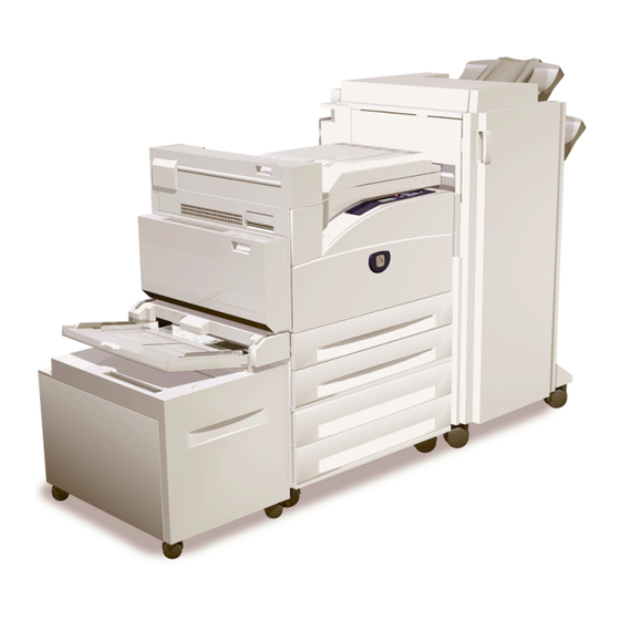
Printer Options Phaser 5500 printer options include: 20 GB Hard Drive Additional RAM and NVRAM Exit 2 Configuration Card 1000-Sheet Feeder (Tray 4 & 5) Duplex Unit 3,500-Sheet Stacker (with offset) 3,500-Sheet Finisher (with hole punch, staple, offset) 2,000-Sheet Feeder (Tray 6) -
Page 31: 1000-Sheet Feeder
1000-Sheet Feeder The 1000-Sheet Feeder forms a base for the printer and adds two, 500-sheet trays (Tray 4 and Tray 5). Control signals reach the sheet feeder by a single connection. The sheet feeder is secured to the print engine with two screws located under the front edge of Tray 3. -
Page 32: Stacker / Finisher
Stacker/Finisher options and job specifications, as paper enters the Stacker/ Finisher it is punched, stapled, offset and stacked. Control signals reach the Stacker/ Finisher through a single connector. Power is supplied from the printer’s AC Accessory Panel. s5500-009 1. Horizontal Transport 2. Stacker/Finisher Phaser 5500 Printer Service Manual... -
Page 33: 2000-Sheet Feeder
2000-Sheet Feeder The 2000-Sheet Feeder (Tray 6) nearly doubles the input capacity of the printer. The feeder attaches to the left side of printers equipped with the 1000-Sheet Feeder option just below Tray 1/MPT using the supplied docking bracket. Electrical connection to the printer is made by an interface cable. -
Page 34: Consumables And Routine Maintenance Items
Print life ratings are based on 5% coverage and an average job length of 6 pages. Consumables Print Life (Number of Images) Toner Cartridge 30,000 Routine Maintenance Items Fuser 300,000 Drum Cartridge 60,000 Maintenance Kit (consists of Fuser, 300,000 Transfer Roller and 15 Feed Rollers) 1-10 Phaser 5500 Printer Service Manual... -
Page 35: Printer Specifications
Printer Specifications Physical Dimensions Device Height Width Depth Weight Print Engine 498 mm (19.6 in.) 640 mm (25.2 in.) 525 mm (20.7 in.) 41 kg (90 lbs.) Duplex Unit 211 mm (8.3 in.) 64 mm (2.52 in.) 458 mm (18.0 in.) 1.8 kg (4 lbs.) 1000-Sheet 280 mm (11.0 in.) - Page 36 (47 in.) 46 cm (18 in.) 119 cm 100 cm (47 in.) (39 in.) 46 cm 20 cm (18 in.) (8 in.) 218 cm (86 in.) 65 cm (26 in.) 118 cm (46 in.) s5500-610 1-12 Phaser 5500 Printer Service Manual...
-
Page 37: Functional Specifications
Functional Specifications Characteristic Specification Printing process: Recording System: Electrophotography (roller charging, magnetic dual component toner and DRUM Cartridge) Exposure System: Semiconductor laser beam scanning Transfer System: Roller transfer system Fusing System: Thermal fixing using a heat roller Resolution / 600/ True 1200 dpi Addressability Print-Quality Two choices:... -
Page 38: Environmental Specifications
500 Sheets Tray 5 500 Sheets Tray 6 2000 Sheets Top (face-down) 500 Sheets Stacker/Finisher 3000 elevator, 500 in top tray Based on 75 g/m (20 lb.) paper stock. Capacity is reduced for heavier/thicker stock. 1-14 Phaser 5500 Printer Service Manual... - Page 39 Supported Paper Specifications Paper Sizes and Weights User-Selected Size Input Output Auto-Sensed Size Supported Supported only when Long-Edge Feed Depending on your region, finishers are configured with either a 3-hole punch or a 2-hole and 4-hole punch. These custom widths are supported with stapling and hole punching: 210 mm (8.27 in.), 257 mm (10.12 in.), 297 mm (11.70 in.), 8.50 in.
- Page 40 Envelope Custom Width / Envelope Custom Height 148–241 mm (5.82–9.50 in.)/ 98–162 mm (3.87–6.38 in.) Paper Weight 60–105 g/m (16–28 lb. Bond) 105–120 g/m (28–32 lb. Bond) 120–176 g/m (32–47 lb. Bond) 176–215 g/m (47–57 lb. Bond) 1-16 Phaser 5500 Printer Service Manual...
-
Page 41: Theory Of Operation
Theory of Operation In this chapter... Phaser 5500 Operational Overview Paper Path Sensors Xerographics Major Assemblies Chapter... -
Page 42: Phaser 5500 Operational Overview
This section focuses on the printer’s operational characteristics providing detailed descriptions of the paper path, sensors, xerographics and major system assemblies. Operational details of the available options appear in Book 2, Phaser 5500 Printer Options Service Manual. Summary of the Printing Process The illustration below shows the orientation of the major components associated with the xerographics process as viewed from the front of the printer. - Page 43 Movable actuators located in the paper tray indicate the location of the guides. The Phaser 5500 uses a three-roller system to pick paper. A DC motor raises the tray's lift plate, along with the paper stack, against the Nudger Roller of the paper feeder assembly.
-
Page 44: Paper Handling
Drum Motor The rotating force of the Drum Motor is transmitted through the gears to components that need mechanical driving force as shown in the following flow. Drum Motor Drum Magnetic Roller Transfer Roller s5500-021 Phaser 5500 Printer Service Manual... -
Page 45: Input Paper Path
The driving force transmitted to the Drum Cartridge drives the Drum. The driving force is then transmitted to the Transfer Roller by direct contact with the Drum. Input Paper Path Paper supplied from each tray is transported through the printer along the paper path shown below. - Page 46 Tray 1/MPT Pick-up Solenoid causing the Feed Roller to rotate. When the Feed Roller contacts the paper, a sheet is fed into the gap between the Feed Roller and the Pinch Rollers. Phaser 5500 Printer Service Manual...
-
Page 47: Output Paper Path
Registration Roller. Output Paper Path The Phaser 5500 paper path for paper exiting the fuser are: Direct through Exit 1 to the Output Tray on the Top Cover (facedown). Direct through Exit 1, the Horizontal Transport to the Stacker Trays. - Page 48 Left and Right Shaft assemblies. The paper is held between the belts and pinch rollers located on the inside of Door F. To Finisher From Exit 1 Belt Entrance Sensor Exit Sensor s5500-025 Phaser 5500 Printer Service Manual...
- Page 49 Finisher/Stacker What follows is a summary of the output path through the Finisher. A detailed description of the Finisher paper path appears in Book 2, Chapter 2. Top Exit Rollers (Driven by Exit Motor) Transfer Rollers (Driven by Regi Motor) Transfer Gate Sub Paddle (Driven by Finisher Transport...
-
Page 50: Duplex Path
The Duplex Unit provides duplex printing for paper fed from all available paper trays except the Envelope Tray, which cannot be duplexed. Exit 2 Exit Sensor Fuser Exit Sensor Wait Sensor Registration Sensor Pre Feed Sensor s5500-583 2-10 Phaser 5500 Printer Service Manual... -
Page 51: Sensors
Sensors The printer contains sensors of various types that perform a variety of functions. One group of sensors track the progress of the paper along the paper path, and detect if a paper jam occurs. Other sensors detect the presence of the Drum Cartridge, stop printer activity if a door is open (interlock), and monitor the fusing temperature. - Page 52 Senses the position of the Offset Chute. Environmental Integrated circuit PWB Monitors the printer’s Temp and humidity. CRUM antenna Inductive code reader Communicates with the CRUMs. OCT Home Photo-receptive Detects Offset assembly home position. Position 2-12 Phaser 5500 Printer Service Manual...
-
Page 53: Sensors In The Paper Path
Sensors in the Paper Path The following illustrations show the designations of the various sensors located along the paper path. Error reporting is dependent on these designators. Error detection is based on paper transport timing through the sensing area. Door Interlock Sensors The Interlock Sensors for Doors A through E and J, as well as selected paper feed sensors appear in the following diagram. -
Page 54: Paper Feed Sensors
These signals identify what size of paper has been loaded and what to display on the Front Panel. Also, any actuation of the paper size sensor signals the Engine Logic Board that the tray is present and closed. 2-14 Phaser 5500 Printer Service Manual... -
Page 55: Xerographics
Paper Level Sensing As paper is fed from the tray, the paper level drops. When the paper level reaches a certain point, an actuator unblocks the Level Sensor signaling the control logic to stop paper feed and raise the tray bottom. Raising the tray bottom pushes the paper up to achieve optimum force against the Feed Roller and blocks the Level Sensor resuming paper feed. -
Page 56: Transfer Roller
Thus, the developed image is transferred from the surface of the drum to the surface of the paper. The Detack Saw, located adjacent to the Transfer Roller, helps to separate the paper from the drum surface. 2-16 Phaser 5500 Printer Service Manual... -
Page 57: Toner Dispense Assembly
Transfer Roller Left s5500-607 Toner Dispense Assembly The Toner Dispense Assembly operates the Toner Cartridge dispense door and moves toner from the cartridge through a dispense tube to the Drum Cartridge. Toner Dispense Dispense Assembly Tube s5500-594 Theory of Operation 2-17... -
Page 58: Toner Dispense Motor
The Scanner Motor turns on when it receives a signal, and turns off after printing ends. The Scanner Motor remains off in the standby and power-saving states. 2-18 Phaser 5500 Printer Service Manual... - Page 59 Start Of Scan Dual Beam Laser Diode Polygon Mirror Scanner Motor s5500-030 The Laser Assembly is field replaceable and contains the laser diodes, scanner motor/mirror, and several lenses and mirrors. The Laser Assembly “reflects” the laser beam so it strikes the Drum. Caution Never remove the cover from a Laser Assembly for any reason - contamination may result.
- Page 60 SOS signal interval (equivalent to 98% or more of the rated rpm of the Scanner Motor) Fail reference value SOS signal interval (equivalent to 90% or less of the rated rpm of the Scanner Motor) 2-20 Phaser 5500 Printer Service Manual...
-
Page 61: Fuser
Fuser The Fuser, using a combination of heat and pressure, bonds the toner to the paper. As an FRU, the Fuser is replaced as a unit. Rear Thermistor Main Heater Rod Center Thermistor Pressure Roller Heater Rods Thermistor Pressure Roller Heat Roller Thermostat s5500-032... - Page 62 The life expectancy of the Fuser is 300,000 Letter/A4 size pages. Several factors can reduce Fuser life: Greater than 5% coverage Paper use larger than letter size Printing on heavy media Printing short-edge feed Printing on transparencies or specialty media 2-22 Phaser 5500 Printer Service Manual...
- Page 63 Power Shutoff to the Fuser The printer shuts off power to the Fuser for the following reasons: Fuser abnormality (U4) Paper jam Cover Open - Doors A, B, C, D, Front Door Laser Assembly abnormality (U3) CPU or NVRAM abnormality (U6) Motor Assembly abnormality (U0, U1) Fuser Fan abnormality (U4) Fuser Problems (U4 Error Code)
- Page 64 Plain Paper Thick Paper Thick Paper Envelopes Mode 2 Mode 1 Mode 1 (Default) Mode 2 Prepunched Plain Paper Plain Paper Thick Paper Thick Paper Mode 2 Mode 1 and Mode 1 Mode 2 (Default) 2-24 Phaser 5500 Printer Service Manual...
- Page 65 Fuser Control Temperatures The following tables list the control temperatures for the Fuser when different paper types (Modes) are selected. Fuser Control Temperatures for Plain Paper Modes and Transparency Paper Type Plain Paper Transparency Mode Thin Paper Normal Paper Max (Cold) Min (Hot) Max (Cold) Max (Cold) (Hot) (Hot)
-
Page 66: Major Assemblies And Functions
Major Assemblies and Functions Components of the Phaser 5500 printer described in this section include: Trays Exit 1 Assembly Printer Drive and Electrical Trays Standard trays include the 100-sheet, multi-purpose Tray 1/MPT and two 500-sheet universal trays, Trays 2 and 3. The trays adjust to accept various paper sizes. - Page 67 Trays 2 and 3 The universal trays 2 and 3 include end and side guides that manually adjust to the paper loaded in the tray. These guides come into contact with the front and rear edges of the paper and hold it in position. Paper size is determined by the position of the switches in the Paper Size Switch assembly.
- Page 68 Level Sensor’s sensing area, triggering the Feed/Lift Motor to raise the Bottom Plate. The Feeder’s Feed/Lift Motor raises the Bottom Plate by rotating the Lift-up Shaft through the Gear (13T/60T) and Sector Gear (60T). 2-28 Phaser 5500 Printer Service Manual...
- Page 69 Lift Up Shaft Sector Gear (60T) Gear 13T/60T s5500-034 The paper supply and path are monitored by these sensors located on the Tray 2 and Tray 3 Feeders. Level Sensor The Level Sensor uses an actuator to determine whether paper in the tray is lifted to the optimum feeding position.
-
Page 70: Exit 1 Assembly
Standard Output Tray or Horizontal Transport. When it is lowered by the Exit Gate Solenoid, paper is fed to Exit 2. The Exit Gate is operated by the Exit Gate Solenoid located in the Exit 2 module. 2-30 Phaser 5500 Printer Service Manual... - Page 71 Offset Motor The Offset Motor acting through the Offset Gear shifts the OCT Roller forward or backward providing paper offset capability. Forward rotation shifts the OCT Roller to the front. Reverse rotation shifts it to the rear. The flow diagram shows the Exit 1 components involved in the Offset process.
-
Page 72: Printer Drive And Electrical
Engine Logic Board. Main Motor Drum Motor Motor Assembly s5500-040 Toner Dispense Motor This drives the Toner Cartridge and dispense tube auger to gradually release toner to the Drum Cartridge. Toner Dispense Motor s5500-596 2-32 Phaser 5500 Printer Service Manual... - Page 73 Printer Control Drum Cartridge Detect Interlock Drum Cartridge Power Switch Front Door Door A Interlock Interlock Exit PWB Fuser Fan Image Processor Board Door B Interlock Engine Logic LVPS Board HVPS GFI Breaker s5500-041 Printer control centers on the following: Power Switch The Power switch controls main power to the printer.
- Page 74 The Image Processor Board (I/P Board) is one of the major elements of the Phaser 5500 printer. The primary function of the I/P Board is to receive host data through one of the following available ports (Parallel, USB, or Ethernet). The received host data is buffered and stored and sent to the print engine in a rasterized format.
- Page 75 Engine Logic Board The Engine Logic Board manages the printing operation according to information obtained through communications with the I/P Board and from sensors and switches located throughout the printer. The Engine Logic Board performs seven main functions: Communicates with the Image Processor. Controls the print sequence.
- Page 76 Exit PWB The Exit PWB controls timing, feed, and motor operation for Exit 1 and the optional Exit 2. Exit PWB s5500-044 HVPS The HVPS provides high AC and DC voltages to Xerographic components. s5500-043 2-36 Phaser 5500 Printer Service Manual...
- Page 77 Located behind the Inner Main Cover, the High Voltage Power Supply (HVPS) provides power to the Bias Charge Roller, Magnetic Roller, Transfer Roller, and Detack Saw. LVPS The Low-Voltage Power Supply (LVPS) generates low voltages (+5 V and +3.3 V for logic circuits, +5 V for Laser Diodes, and +24 V for motors/clutches) from AC power.
- Page 78 AC Accessory Panel The AC Accessory Panel provides AC power for the Finisher and accepts the Printer Power Cord. AC Accessory Panel Reset Switch GFI Breaker s5500-046 2-38 Phaser 5500 Printer Service Manual...
-
Page 79: Error Messages, Codes, And Procedures
Error Messages, Codes, and Procedures In this chapter... Introduction Power On Self Test (POST) Service Usage Profile Service Diagnostics Error Messages, Codes, and Procedures Chapter... -
Page 80: Introduction
Use the Parts List to locate a part number. Use the FRU Disassembly procedures to replace the part. Step 5: Final Checkout: Test the printer to verify the problem is corrected and no new problems arose. Phaser 5500 Printer Service Manual... -
Page 81: System Startup
System Startup Listed here is a typical printer startup routine from a cold start. When the main power switch is turned on, the ‘Health’ LED on the Image Processor board turns on immediately. The boot loader checks for presence and condition of RAM. If an error is detected, “RAM ERROR”... -
Page 82: Power On Self Test (Post)
Checks that there is no more than 512 MB of memory installed. IDE Disk Soft Checks the disk controller core, and runs a DIAGNOSE command on the hard drive. Engine Hard Checks communication between the Image Processor Board Command and the Engine Logic Board. Phaser 5500 Printer Service Manual... -
Page 83: Post Soft Fault Messages
POST Soft Fault Messages When POST detects a soft error, the printer continues the startup process. Before the printer reaches its “Ready to Print” state, the Start Page is printed with soft errors appearing in a gray box. The box contains all soft faults encountered, with the upper left corner of the box in the center of the Start Page, and extending to the right margin, similar to the one shown here. -
Page 84: Post Hard Fault Messages
Image Processor USB port failure. Replace Image Processor Board (page 8-91). 5+5+5+5+1+1 22: ENGINE Communication with print engine has failed. Check the COMMAND connection to the Engine Logic Board, then go to “Image Processor Isolation” on page 4-13. Phaser 5500 Printer Service Manual... -
Page 85: Service Usage Profile
Service Usage Profile The Service Usage Profile tracks printer activity, consumable usage and printer history. This data is stored in NVRAM. Service Usage Profile data includes error logs that retain detail on the type, date, location and frequency of engine and jam errors. While the Service Usage Profile includes data on all aspects of the printer, this section focuses on accessing these two error logs to review printer history. - Page 86 Incorrect Finisher (H5-8) If Engine Error codes appear in either the Engine Error Log or on the Front Panel, use the Fault Code to find the corresponding troubleshooting procedure in the Error Message Summary table. Phaser 5500 Printer Service Manual...
-
Page 87: Jam Errors
Jam Errors The following table lists the fault history codes used in the Service Usage Profile to record jam errors. Last Jam Location is recorded on line 291. Last Jam Error Codes appear at line 298, and Last Jam Page number appears on line 294. A partial example of the Last Jam Error Log as it is displayed on the Front Panel: --;--;--;--;--;--;--;--;--;--;--;C4-0,<pg_count>;C4-1,<pg_count>;... - Page 88 Refer to this diagram when questions arise regarding the area of the jam. Door H Door E Door F Door A Door D Door G Door J Door C Door B s5500-614 3-10 Phaser 5500 Printer Service Manual...
-
Page 89: Service Diagnostics
Service Diagnostics Service Diagnostics provide tests for most electro-mechanical components in the printer. Service Diagnostics also contains test prints, printer status and some NVRAM access. Test descriptions appear in the Appendix. The Service Diagnostics Main menu offers the options listed in the following table. Service Diagnostics Main Menu Menu Item Test Target... -
Page 90: Using Service Diagnostics
Map, and pressing the OK button. The printer runs through POST and returns to Ready. You will need to re-enter Service Diagnostics. The Service Diagnostics Menu Map also appears in the Appendix. See “Service Diagnostics Menu Map” on page A-4. 3-12 Phaser 5500 Printer Service Manual... -
Page 91: Service Diagnostics Controls
Service Diagnostics Controls Button Function BACK Returns to the prior higher level menu structure, if available. If help text is displayed, pressing BACK restores the current menu item and removes the help text. CANCEL Terminates the current test or cancels current INFO display. INFO Provides help information, if available. -
Page 92: Messages, Codes, And Procedures
Device used to store usage information on the Unit Monitor Drum and Toner Cartridges. Comm Communication As in MCU-DM Comm Error. LVPS Low-Voltage Power Supply Primary power supply. Printed Wire Board Used to describe a circuit board (Tray 6 PWB). 3-14 Phaser 5500 Printer Service Manual... -
Page 93: Error Message Summary
Error Message Summary The Error Message Summary below lists possible error messages, along with, the corresponding Service Diagnostic message and Service Usage Profile fault code. The Front Panel Message column shows the message as is appears on the printer’s display when the error occurs during normal operation. - Page 94 F4-24 H-Xport Exit SNR ON Jam C 3-91 Jam at F F4-26 H-Xport Exit SNR Static 3-93 Jam at F F4-32 X’port Ent SNR ON 3-95 Jam at F F4-36 X’port Ent SNR Static 3-98 3-16 Phaser 5500 Printer Service Manual...
- Page 95 Error Message Summary (Continued) Engine Go to Front Panel Message Service Diagnostics Message Error Error Page Jam at G F4-42 Buffer Path SNR ON Jam A 3-101 Jam at G F4-43 Buffer Path SNR ON Jam B 3-101 Jam at G F4-46 Buffer Path SNR Static Jam A 3-106 Jam at G...
- Page 96 3-200 Replace Drum Cartridge J6-1 DRUM end of life 3-200 Drum Cartridge Failure J7-1 DRUM Comm Error 3-201 Drum Cartridge Failure J7-2 DRUM NVRAM Error 3-200 Non-Xerox Drum Cartridge J7-3 DRUM type mismatch 3-200 3-18 Phaser 5500 Printer Service Manual...
- Page 97 Error Message Summary (Continued) Engine Go to Front Panel Message Service Diagnostics Message Error Error Page Install or Reseat Toner J8-1 Toner Comm Error 3-204 Cartridge Toner Cartridge Failure J8-2 Toner Cart. read/write error 3-204 Replace Incorrect Toner J8-3 Toner Cart. type mismatch 3-205 Cartridge Non-Xerox Toner Cartridge...
-
Page 98: Using The Troubleshooting Procedures
Remember that disassembly procedures, parts lists, and wiring diagrams for printer options appear in the Phaser 5500 Printer Options Service Manual. Follow each Step in a troubleshooting procedure sequentially in the order given until the problem is fixed or resolved. -
Page 99: Measurement Techniques
Measurement Techniques Unless indicated otherwise, the instruction “switch On printer main power” means for you to switch On printer power and let the printer proceed through POST to a ‘Ready’ condition. When instructed to take voltage, continuity or resistance readings on wiring harness, proceed as follows: Check P/J 232–1 to P/J 210–5 by placing the red probe (+) of your meter on pin 1 of P/J 232, and place the black probe (–) of your meter on pin 5 of P/J 210. -
Page 100: Entry Level Fault Isolation Procedure
4-13. Request the customer send a print job Problem solved; Go to “Network from their application. return to Final Problems” Did the job print successfully? Checkout in the page 4-2. Service Flowchart. 3-22 Phaser 5500 Printer Service Manual... -
Page 101: Main Motor Failure
Main Motor Failure The Main Motor stopped or didn’t start on time. Applicable Error Codes Main Motor Failure - U0-1 Main Motor Stop Main Motor Failure - U1-1 Main Motor Rotation Main Motor Troubleshooting Reference Applicable Parts References Motor Assembly Print Engine P/J Electrical (page 10-12) Engine Logic Board Print Engine Drive/Crum Wiring (page 10-25) -
Page 102: Drum Motor Failure - U1-4 Drum Motor Rotation
Connect the Are P/J214 and P/J408 connected? Motor. Check continuity between the Motor Go to Step 8. Repair the wiring. Assembly and Engine Logic Board. Is there continuity on each wire between P/J214 <=> P/J408? 3-24 Phaser 5500 Printer Service Manual... -
Page 103: Laser Unit Failure - U3-3 Laser Power
Drum Motor Troubleshooting Procedure (Continued) Step Actions and Questions Check for +24 V to the Motor Replace the Motor Replace the Is there +24 V across P/J214-1/-2 (+) <=> Assembly Engine Logic ground? (page 8-84). Board (page 8-89). Laser Unit Failure - U3-3 Laser Power The Laser Assembly has failed. -
Page 104: Laser Motor Failure - U3-5 Polygon Motor Rotation
Run the Service Diagnostics Laser Scan Assembly or Motor test. Engine Logic Does the motor run? Board. Check the Laser connection. Go to Step 4. Connect the Are P/J140 and P/J406 connected? Laser Assembly. 3-26 Phaser 5500 Printer Service Manual... -
Page 105: Fuser Failure - U4-1 On Time
Scanner Motor Troubleshooting Procedure (Continued) Step Actions and Questions Check the Laser connections. Go to Step 5. Connect P/J130, Are P/J130, P/J620 and P/J406 P/J620 and P/ connected? J406. Check continuity between the Laser and Go to Step 6. Repair the wiring. the Engine Logic Board. - Page 106 P/J132-2 greater than or equal to (page 8-76). 3 k-ohm? Check Fuser resistance. Go to Step 10. Replace the Is the resistance across P/J133-1 and P/ Fuser J133-2 greater than or equal to (page 8-76). 3 k-ohm? 3-28 Phaser 5500 Printer Service Manual...
-
Page 107: Fuser Failure - U4-N Over Heat / Thermistor
Fuser On Time Troubleshooting Procedure (Continued) Step Actions and Questions Check the Fuser connection. Go to Step 11. Connect P/J6. Is P/J6 connected? Check continuity between the Fuser and Go to Step 12. Repair the wiring. LVPS. Is there continuity on each wire between P/J600 <=>... -
Page 108: Fuser Failure - U4-7 Cold Sagging
The Fuser temperature regulation failed. Note Following display of this error, leave power applied for 7 minutes, then cycle printer power. If the error reoccurs, proceed with troubleshooting procedure. Applicable Error Code Fuser Failure - U4-7 Cold Sagging 3-30 Phaser 5500 Printer Service Manual... - Page 109 Fuser Cold Sagging Troubleshooting Reference Applicable Parts References Fuser Print Engine P/J Fuser and Exit 1 (page 10-8) LVPS “Print Engine Fuser Wiring (page 10-22) Engine Logic Board PL6.1 Fuser and Exit 1 Unit (page 9-34) PL8.1 Print Engine Electrical (page 9-40) Fuser Cold Sagging Troubleshooting Procedure Step Actions and Questions...
-
Page 110: Fan Failure - U4-9 Fan Defect
Is there continuity on each wire? Check for +24 V to the Fuser Fan. Replace the Fan Replace the Is there +24 V across CN102-3(+) <=> (page 8-59). Engine Logic ground? Board (page 8-89), then replace the Motor Assembly. 3-32 Phaser 5500 Printer Service Manual... -
Page 111: Toner Motor Failure - U5-1 Motor Rotation
Toner Motor Failure - U5-1 Motor Rotation The Toner Dispense Motor failed to rotate. Applicable Error Codes Toner Motor Failure - U5-1 Motor Rotation Troubleshooting Reference Applicable Parts References Toner Cartridge Print Engine P/J Drum and Toner Cartridge (page 10-6) Toner Dispense Assembly Print Engine Xerographics Wiring (page 10-24) -
Page 112: Fan Failure - U5-9 Fan Failure
Test the Drum Cartridge Fan. Replace the Fan Replace the Run the Service Diagnostic Drum (page 8-58) Engine Logic Cartridge Fan test. Board Does the Fan receive the voltage from (page 8-89). the test? 3-34 Phaser 5500 Printer Service Manual... -
Page 113: Engine Logic Board Failure - U6-2, 3, 4, 5, 7
Engine Logic Board Failure - U6-2, 3, 4, 5, 6, 7 Engine Logic Board components have failed. Applicable Error Codes Engine Logic Board Failure - U6-2 RAM Read/Write Engine Logic Board Failure - U6-3 NVM Data Defect Engine Logic Board Failure - U6-4 NVM Read/Write Engine Logic Board Failure - U6-5 CP/U Power NVM Engine Logic Board Failure - U6-6 ASIC/CRUM Engine Logic Board Failure - U6-7 PPM Data... - Page 114 Are P/J215 and P/J403B connected? and P/J403B. Check continuity between the Registration Go to Step 10. Repair the wiring. Clutch and Engine Logic Board. Is there continuity on each wire between P/J215 <=> P/J403? 3-36 Phaser 5500 Printer Service Manual...
-
Page 115: Jam At A - E1-2 Regi Area Jam
Paper Size Jam (Registration Sensor) Troubleshooting Procedure (Continued) Step Actions and Questions Check for +24 V to the Registration Clutch. Go to Step 11. Replace the Is there +24 V across P215-2 (+) <=> Engine Logic ground? Board (page 8-89). Check Registration Clutch resistance. -
Page 116: Jam At A - E1-6 Regi Area Jam
Clutch (page 8-89). (page 8-51). Jam at A - E1-6 Regi Area Jam Paper remains at the Registration Sensor located behind Door A. Applicable Error Code Jam at A - E1-6 Regi Area Jam 3-38 Phaser 5500 Printer Service Manual... -
Page 117: Jam At A - Fuser Area Jam
E1-6 Regi Area Jam (Registration Sensor) Troubleshooting Reference Applicable Parts References Registration Print Engine P/J Registration Transport (page 10-10) Sensor Print Engine Registration Transport Wiring (page 10-23) Engine Logic PL4.5 Registration (page 9-30) Board PL8.1 Print Engine Electrical (page 9-40) E1-6 Regi Area Jam (Registration Sensor) Troubleshooting Procedure Step Actions and Questions... - Page 118 P/J125 <=> P/J410? Check for +5 V to the Fuser Exit Sensor. Replace the Fuser Replace Engine Is there +5 V across J125-3 (+) <=> Exit Sensor Logic Board ground? (page 8-77). (page 8-89). 3-40 Phaser 5500 Printer Service Manual...
-
Page 119: Jam At A - E3-6 Fuser Area Jam
Jam at A - E3-6 Fuser Area Jam Paper remains at the Fuser Exit Sensor located behind Door A. Applicable Error Code Jam at A - E3-6 Fuser Area Jam E3-6 Fuser Area Jam Troubleshooting Reference Applicable Parts References Fuser Exit Print Engine P/J Drum and Toner Cartridge (page 10-6) Sensor Print Engine Fuser Wiring (page 10-22) -
Page 120: Jam At A - E4-1 Exit 2 Area Jam
Are P/J125 and P/J410 connected? sensor. Check continuity between the Fuser Exit Go to Step 8. Repair the wiring. Sensor and Engine Logic Board. Is there continuity on each wire between P/J125 <=> P/J410? 3-42 Phaser 5500 Printer Service Manual... - Page 121 E4-1 Exit 2 Area Jam Troubleshooting Procedure (Continued) Step Actions and Questions Check for +5 V at the Fuser Exit Sensor. Replace the Fuser Replace the Is there +5 V across the sensor Exit Sensor Engine Logic connector’s P/J125-3 <=> ground? (page 8-77).
-
Page 122: Jam At E - E4-3 Exit 2 Area Jam
Paper did not pass the Exit 2 Exit Sensor located behind Door E on time. Applicable Error Codes Jam at E - E4-3 Exit 2 Area Jam Jam at A - E4-5 Exit 2 Area Jam 3-44 Phaser 5500 Printer Service Manual... - Page 123 Print Engine Exit 1 Wiring (page 10-30) Exit 2 OCT Roller PL8.1 Print Engine Electrical (page 9-40) Exit 2 FU Roller Phaser 5500 Printer Options Service Manual Exit 2 Inv Roller Exit 2 Plug/Jack Locator (page 5-15) Exit PWB Exit 2 General Wiring (page 5-7) Engine Logic Board PL24.1 Exit 2 L/H Upper Chute (page 4-38)
- Page 124 Is there continuity on each wire between P/J430 <=> P/J526? Check for +24 V to the Exit PWB. Replace the Exit Replace the Is there +24 V across P/J430-1 (+) <=> PWB (page 8-88). LVPS ground? (page 8-92). 3-46 Phaser 5500 Printer Service Manual...
-
Page 125: Jam At E - E4-6 Exit 2 Area Jam
E4-3 Exit 2 Area Jam Troubleshooting Procedure (Continued) Step Actions and Questions Test the Exit 2 Motor operation. Replace the Go to Step 21. Run the Service Diagnostics Exit 2 Output Engine Logic Motor tests. Board Does the Exit 2 Motor operate properly? (page 8-89). - Page 126 Print Engine P/J Laser and Exit PWB (page 10-7) Engine Logic Board Print Engine Exit 1 Wiring (page 10-30) LVPS Phaser 5500 Printer Options Service Manual Exit 2 Plug/Jack Locator (page 5-15) Exit 2 General Wiring (page 5-7) PL8.1 Print Engine Electrical (page 9-40) PL24.2 Exit 2 Tray Guide Assembly (page 4-40)
-
Page 127: Jam At E - E8-2 Duplex Area Jam
Print Engine Exit 1 Wiring (page 10-30) Exit 2 OCT Roller PL8.1 Print Engine Electrical (page 9-40) Exit 2 FU Roller Phaser 5500 Printer Options Service Manual Exit 2 Inv Roller Exit 2 Plug/Jack Locator (page 5-15) Exit PWB Exit 2 General Wiring (page 5-7) - Page 128 Is there continuity on each wire between P/J430 <=> P/J526? Check for +24 V to the Exit PWB. Replace the Exit Replace the Is there +24 V across P/J430-1 (+) <=> PWB (page 8-88). LVPS ground? (page 8-92). 3-50 Phaser 5500 Printer Service Manual...
-
Page 129: Jam At D And A - C6-1 Duplex Area Jam
E8-2 Duplex Area Jam Troubleshooting Procedure (Continued) Step Actions and Questions Test the Wait Sensor. Replace the Go to Step 18. Run the Service Diagnostics Duplex Wait Engine Logic Sensor test. Board Does the Wait Sensor operate properly? (page 8-89). Check the Wait Sensor connection. - Page 130 Duplex Motor PL4.5 Registration (page 9-30) Duplex PWB PL8.1 Print Engine Electrical (page 9-40) Engine Logic Board Phaser 5500 Printer Options Service Manual Registration Sensor Duplex Unit Plug/Jack Locator (page 5-12) Duplex Unit Wiring (page 5-13) PL23.1 Duplex Unit (page 4-34) PL23.2 Inner Chute Duplex Unit (page 4-36)
-
Page 131: Jam At D And A - C6-2 Duplex Area Jam
C6-1 Duplex Area Jam Troubleshooting Procedure (Continued) Step Actions and Questions Check the Duplex Motor for continuity. Go to Step 10. Repair the wiring. Is there continuity on each wire between P/J212 <=> P/J542? Check for +24 V to the Duplex Motor. Go to Step 14. - Page 132 Print Engine Registration Transport Wiring (page 10-23) Duplex Motor PL4.5 Registration (page 9-30) Duplex Wait PL8.1 Print Engine Electrical (page 9-40) Sensor Phaser 5500 Printer Options Service Manual Duplex PWB Duplex Unit Plug/Jack Locator (page 5-12) Engine Logic Board Duplex Unit Wiring (page 5-13) Registration PL23.1 Duplex Unit (page 4-34)
- Page 133 C6-2 Duplex Area Jam Troubleshooting Procedure (Continued) Step Actions and Questions Test the Wait Sensor. Go to Step 14. Go to Step 9. Run the Service Diagnostics Duplex Wait Sensor test. Does the Wait Sensor operate properly? Check the Wait Sensor connection. Go to Step 10.
-
Page 134: Jam At Tray N - Pre-Feed
Applicable Error Codes Jam at Tray 2 - C1-2 Tray 2 Jam at Tray 3 - C2-1 Tray 3 Jam at Tray 4 - C3-0 Tray 4 Jam at Tray 5 - C4-4 Tray 5 3-56 Phaser 5500 Printer Service Manual... - Page 135 PL2.3 Feeder (2/2) (page 9-12) Pre-Feed Sensor PL8.1 Print Engine Electrical (page 9-40) Feed/Lift Motor Phaser 5500 Printer Options Service Manual Engine Logic Board 1000-Sheet Feeder P/J Locator (page 5-5) Tray 4-5 PWB 1000-Sheet Tray 4 & 5 Wiring (page 5-9) PL20.6 Tray 4-5 Drive and Electrical (page 4-16)
- Page 136 P/J409A? Check +24 V power supply to the Feed/Lift Replace the Feed/ Replace the Motor. Lift Motor. Engine Logic Is there +24 V across the motor Board connector’s Pin 4 <=> ground? (page 8-89). 3-58 Phaser 5500 Printer Service Manual...
-
Page 137: Jam At Tray N - Registration
PL2.3 Feeder (2/2) (page 9-12) Registration Sensor PL8.1 Print Engine Electrical (page 9-40) Tray 2 Pre-Feed Sensor Phaser 5500 Printer Options Service Manual Tray 3 Pre-Feed Sensor 1000-Sheet Feeder P/J Locator (page 5-5) Engine Logic Board 1000-Sheet Tray 4 & 5 Wiring (page 5-9) Tray 4-5 PWB PL20.4 Tray 4-5 Feeders (2/2) (page 4-10) - Page 138 Sensor test for the appropriate tray. Does the sensor change state? For Trays 4 and 5 Only: Go to Step 15. Connect the Check the appropriate Feed Out Sensor sensor. connection. Is the sensor’s connected? 3-60 Phaser 5500 Printer Service Manual...
-
Page 139: Jam At Tray N - Feed Out #3
Jam at Tray n (Registration Sensor) Troubleshooting Procedure (Continued) Step Actions and Questions For Trays 4 and 5 Only: Go to Step 16. Repair the wiring. Check continuity between the Feed Out Sensor and the Tray 4-5 PWB. Is there continuity on each wire between the sensor and board For Trays 4 and 5 Only: Replace the... - Page 140 PL2.3 Feeder (2/2) (page 9-12) Feed Out Sensor #3 PL8.1 Print Engine Electrical (page 9-40) Engine Logic Board Phaser 5500 Printer Options Service Manual Tray 4-5 PWB 1000-Sheet Feeder P/J Locator (page 5-5) Tray 4 Feed Out Sensor 1000-Sheet Tray 4 & 5 Wiring (page 5-9) Tray 5 Feed Out Sensor PL20.4 Tray 4-5 Feeder (2/2) (page 4-10)
-
Page 141: Jam At Tray N - Feed Out #4
Jam at Tray n (Feed Out Sensor #3) Troubleshooting Procedure (Continued) Step Actions and Questions For Trays 4 and 5 Only: Replace the Go to Step 10. Test the tray’s Feed Out Sensor. Engine Logic Board 1. Open Door C (page 8-89). - Page 142 Print Engine P/J Engine Logic Board (page 10-13) Retard Roller PL8.1 Print Engine Electrical (page 9-40) Nudger Roller Phaser 5500 Printer Options Service Manual Engine Logic Board 1000-Sheet Feeder P/J Locator (page 5-5) Tray 4-5 PWB 1000-Sheet Tray 4 & 5 Wiring (page 5-9) Tray 4 Feed Out Sensor #4 PL20.4 Tray 4-5 Feeder (2/2) (page 4-10)
-
Page 143: Jam At Tray 5 - C4-0 Tray 5
Jam at Tray n (Feed Out Sensor #4) Troubleshooting Procedure (Continued) Step Actions and Questions Check continuity between the Tray 4-5 and Go to Step 11. Repair the wiring. the Engine Logic Board. Is there continuity on each wire between P/J541 <=> P/J413? Check for +24 V at the Tray 4-5 PWB Replace the Tray Replace the... - Page 144 Print Engine P/J Engine Logic Board (page 10-13) Retard Roller PL8.1 Print Engine Electrical (page 9-40) Nudger Roller Phaser 5500 Printer Options Service Manual Engine Logic Board 1000-Sheet Feeder P/J Locator (page 5-5) Tray 4-5 PWB 1000-Sheet Tray 4 & 5 Wiring (page 5-9) Tray 5 Pre-Feed PL20.4 Tray 4-5 Feeder (2/2) (page 4-10)
- Page 145 Jam at Tray 5 (Feed Out Sensor #5) Troubleshooting Procedure (Continued) Step Actions and Questions Check continuity between the Tray 4-5 Go to Step 11. Repair the wiring. PWB and the Engine Logic Board. Is there continuity on each wire between P/J541 <=>...
-
Page 146: Jam At Tray 6 - C5-1 Tray 6
Print Engine P/J Engine Logic Board (page 10-13) Nudge Roller PL8.1 Print Engine Electrical (page 9-40) Retard Roller Phaser 5500 Printer Options Service Manual Feeder Harness 2000-Sheet Tray 6 Feeder P/J Locator (page 5-20) Main Harness 2000-Sheet Tray 6 Drive P/J Locator (page 5-21) - Page 147 Jam at Tray 6 (Feed Out Sensor #6) Troubleshooting Procedure (Continued) Step Actions and Questions Check the Feeder Harness for continuity Go to Step 7. Repair the Feeder Harness. 1. Disconnect PF61 and PF56B. 2. Check for continuity of the following: PF61-1 <=>...
- Page 148 2. Check for continuity at the following: PF56A-6 <=> JF06-13 PF56A-5 <=> JF06-14 Are these conductive? Check Nudger Solenoid resistance. Go to Step 24. Replace the Is there some amount of resistance Nudger Solenoid across PF59-1 and PF59-2? (page 3-50). 3-70 Phaser 5500 Printer Service Manual...
-
Page 149: Jam At Tray 6 - C5-2 Tray 6
Print Engine P/J Engine Logic Board (page 10-13) Nudge Roller PL8.1 Print Engine Electrical (page 9-40) Retard Roller Phaser 5500 Printer Options Service Manual Take Away Roller 2000-Sheet Tray 6 Feeder P/J Locator (page 5-20) Door J 2000-Sheet Tray 6 Drive P/J Locator (page 5-21) - Page 150 (page 3-63). sensor is actuated? Test the Take Away Motor. Go to Step 17. Go to Step 11. Run the Service Diagnostics Tray 6 Take Away Motor Slow test. Does the motor rotate normally? 3-72 Phaser 5500 Printer Service Manual...
-
Page 151: Jam At B - C5-3 Tray 6
Jam at Tray 6 (Feed Out Sensor #6) Troubleshooting Procedure (Continued) Step Actions and Questions Check the Main Harness connections. Go to Step 12. Connect and go Are the connectors PF57 and P/JF06 on to Step 12. the Main Harness connected? Print a Test Print. - Page 152 PL5.1 Laser, CRU and Toner Dispense (page 9-32) Front Harness A PL8.1 Print Engine Electrical (page 9-40) Engine Logic Board Phaser 5500 Printer Options Service Manual Take Away Motor 2000-Sheet Tray 6 Feeder P/J Locator (page 5-20) Main Harness 2000-Sheet Tray 6 Drive P/J Locator (page 5-21)
- Page 153 Jam at B (Registration Sensor) Troubleshooting Procedure (Continued) Step Actions and Questions Check for +5 V to the Registration Sensor. Go to Step 8. Replace the Is there +5 V across P403-13 <=> Engine Logic P403-3 on the Engine Logic Board? Board (page 8-89).
-
Page 154: Jam At B - C8-2 F/O3 Snr Static Jam
P/J105 <=> P/J410? Check for +5 V to the Feed Out Sensor #3. Replace the Feed Replace the Is there +5 V across P105-1(+)<=> Out Sensor #3 Engine Logic ground? (page 8-54). Board (page 8-89). 3-76 Phaser 5500 Printer Service Manual... -
Page 155: Jam At C - C8-3 F/O4 Snr Static Jam
Tray 4-5 PWB PL8.1 Print Engine Electrical (page 9-40) Engine Logic Board Phaser 5500 Printer Options Service Manual 1000-Sheet P/J Tray 4 & 5 Feeders (page 5-5) 1000-Sheet P/J Tray 4 & 5 Electrical (page 5-6) 1000-Sheet Tray 4 Wiring (page 5-9) PL20.5 Tray 4-5 Transportation (page 4-14) -
Page 156: Jam At C - C8-4 F/O5 Snr Static Jam
Tray 4-5 PWB PL8.1 Print Engine Electrical (page 9-40) Engine Logic Board Phaser 5500 Printer Options Service Manual 1000-Sheet P/J Tray 4 & 5 Feeders (page 5-5) 1000-Sheet P/J Tray 4 & 5 Electrical (page 5-6) 1000-Sheet Tray 4 Wiring (page 5-9) PL20.5 Tray 4-5 Transportation (page 4-14) -
Page 157: Jam At Tray 6 - C8-5 Hcf F/O Snr Static Jam
Print Engine P/J Engine Logic Board (page 10-13) Retard Roller PL8.1 Print Engine Electrical (page 9-40) Take Away Roller Phaser 5500 Printer Options Service Manual Door J 2000-Sheet Tray 6 Feeder P/J (page 5-20) Pre-Feed Sensor 2000-Sheet Tray 6 Drive P/J (page 5-21) - Page 158 Check the Pre-Feed Sensor signal. Go to Step 33. Replace the Pre- Does the voltage across JF02-5 <=> Feed Sensor PF04-2 on the Tray 6 PWB change, when (page 3-51). the sensor is blocked? 3-80 Phaser 5500 Printer Service Manual...
- Page 159 Jam at Tray 6 (Feed Out Sensor #6) Troubleshooting Procedure (Continued) Step Actions and Questions Test the Feed Out Sensor #6. Go to Step 18. Go to Step 11. 1. Open Door J. 2. Run the Service Diagnostics Tray 6 Feed Out Sensor test.
- Page 160 Check the Main Harness connection. Go to Step 29. Connect and go Are PF57 and JF06 connected? to Step 28. Print a Test Print. Go to Step 29. Problem solved. Does the error still occur? 3-82 Phaser 5500 Printer Service Manual...
-
Page 161: Jam At D - C8-6 Duplex
Print Engine P/J Engine Logic Board (page 10-13) Duplex Unit PWB PL8.1 Print Engine Electrical (page 9-40) Engine Logic Phaser 5500 Printer Options Service Manual Board Duplex Unit Plug/Jack Locator (page 5-12) Duplex Unit Wiring (page 5-13) PL23.1 Duplex Unit (page 4-34) -
Page 162: Jam At Tray 1/Mpt - C9-3 Tray 1/Mpt
Jam at Tray 1/MPT - C9-3 Tray 1/MPT Paper fed from Tray 1/MPT did not reach the Registration Sensor, located behind Door A, on time. Applicable Error Code Jam at Tray 1/MPT - C9-3 Tray 1/MPT 3-84 Phaser 5500 Printer Service Manual... - Page 163 Jam at Tray 1/MPT (Registration Sensor) Troubleshooting Reference Applicable Parts References Feed Roller Print Engine P/J Tray 1/MPT (page 10-9) Drive Roller Print Engine P/J Registration Transport (page 10-10) Registration Sensor Print Engine Tray 1/MPT Wiring (page 10-28) Pick Up Solenoid PL3.2 Tray 1/MPT Lower Frame (page 9-18) Engine Logic Board PL4.5 Registration (page 9-30)
- Page 164 (page 8-36). Check for +24 V to the Pick Up Solenoid. Replace the Pick Replace the Is there +24 V across P205-1 (+) <=> Up Solenoid Engine Logic ground? (page 8-36). Board (page 8-89). 3-86 Phaser 5500 Printer Service Manual...
-
Page 165: Jam At A - F4-12 H-X'port Ent. Snr On
Print Engine P/J Engine Logic Board (page 10-13) H-X’port Pinch Rollers PL8.1 Print Engine Electrical (page 9-40) H-X’port Motor Phaser 5500 Printer Options Service Manual H-X’port Harness Horizontal Transport P/J Locator (page 5-29) H-X’port Entrance Horizontal Transport Wiring (page 5-39) - Page 166 Check for +24 V to the H-’Xport Motor. Go to Step 14. Replace the H- Is there +24 V across J8372-15 <=> ’Xport PWB J8372-7, and J8372-14 <=> J8372-7 on (page 3-247). the H-’Xport PWB? 3-88 Phaser 5500 Printer Service Manual...
-
Page 167: Jam At A Or F - F4-N H-X'port Ent. Snr Static
Jam at F - F4-17 H-X’port Ent. SNR Static Jam B Jam at A or F (H-X’port Entrance Sensor) Troubleshooting Reference Applicable Parts References H-X’port Motor Phaser 5500 Printer Options Service Manual H-X’port Harness Horizontal Transport P/J Locator (page 5-29) H-X’port Entrance Horizontal Transport Wiring (page 5-39) - Page 168 P8372-15 <=> J8379-2 P8372-3 <=> J8379-5 Are these conductive? Check the H-’Xport Motor resistance. Go to Step 12. Replace the H- Is there some amount of resistance ’Xport Motor across P8379-2/5(COM) and P8379-1/3/ (page 3-113). 4/6? 3-90 Phaser 5500 Printer Service Manual...
-
Page 169: Jam At A Or F - F4-N H-X'port Exit Snr On
Print Engine P/J Engine Logic Board (page 10-13) H-X’port Pinch Rollers PL8.1 Print Engine Electrical (page 9-40) H-X’port Motor Phaser 5500 Printer Options Service Manual H-X’port Harness Horizontal Transport P/J Locator (page 5-29) H-X’port Exit Sensor Horizontal Transport Wiring (page 5-39) Finisher H-X’port PWB... - Page 170 Go to Step 11. Connect and go Is the H-’Xport Motor correctly to Step 10. connected to the harness? Print a Test Print. Go to Step 11. Problem solved. Does the error still occur? 3-92 Phaser 5500 Printer Service Manual...
-
Page 171: Jam At F - F4-26 H-X'port Exit Snr Static
Jam at F - F4-26 H-X’port Exit SNR Static Jam at F (H-X’port Exit Sensor) Troubleshooting Reference Applicable Parts References H-X’port Motor Phaser 5500 Printer Options Service Manual H-X’port Harness Horizontal Transport P/J Locator (page 5-29) H-X’port Exit Sensor Horizontal Transport Wiring (page 5-39) Finisher H-X’port... - Page 172 Go to Step 10. Connect and go Is the H-’Xport Motor correctly to Step 9. connected to the harness? Print a Test Print. Go to Step 10. Problem solved. Does the error still occur? 3-94 Phaser 5500 Printer Service Manual...
-
Page 173: Jam At F - F4-32 X'port Ent. Snr On
Jam at F (H-X’port Exit Sensor) Troubleshooting Procedure (Continued) Step Actions and Questions Check the harness for continuity. Go to Step 11. Repair the harness. 1. Disconnect P/J8379 of the H-’Xport Motor, and P8372 on the H-’Xport PWB. 2. Check for continuity at the following: P8372-13 <=>... - Page 174 Jam at F (Transport Entrance Sensor) Troubleshooting Reference Applicable Parts References H-X’port Belts Phaser 5500 Printer Options Service Manual H-X’port Pinch Rollers Horizontal Transport P/J Locator (page 5-29) H-X’port Motor Horizontal Transport Wiring (page 5-39) H-X’port Harness Finisher Main PWB P/J Locator (page 5-35) H-X’port Exit Sensor...
- Page 175 Jam at F (Transport Entrance Sensor) Troubleshooting Procedure (Continued) Step Actions and Questions Check the H-’Xport Exit Sensor signal. Replace the H- Replace the H- Does the voltage across J8372-5 <=> ’Xport PWB ’Xport Exit J8372-4 on the H-’Xport PWB change (page 3-247).
-
Page 176: Jam At F - F4-36 X'port Ent. Snr Static
(page 3-248). Jam at F - F4-36 X’port Ent. SNR Static Remaining paper is detected in the Finisher Transport Entrance Sensor. Applicable Error Code Jam at F - F4-36 X’port Ent. SNR Static 3-98 Phaser 5500 Printer Service Manual... - Page 177 Static Jam at F (Transport Entrance Sensor) Troubleshooting Reference Applicable Parts References X’port Entrance Sensor Phaser 5500 Printer Options Service Manual Harness Main SNR Finisher Main PWB P/J Locator (page 5-35) Harness Ent. Sensor Finisher Sensors (1/2) Wiring (page 5-40)
- Page 178 Finisher Main ground, and J8304-18 <=> ground on the Finisher Main PWB? (page 3-248). Replace the Transport Motor. Replace the Problem solved. Print a Test Print. Finisher Main Does the error still occur? (page 3-248). 3-100 Phaser 5500 Printer Service Manual...
-
Page 179: Jam At G - F4-4N Buffer Path Snr On
Jam at G - F4-43 Buffer Path SNR ON Jam B Jam at G (Buffer Path Sensor ON) Troubleshooting Reference Applicable Parts References Entrance Roller Phaser 5500 Printer Options Service Manual Entrance Pinch Roller Finisher Main PWB P/J Locator (page 5-35) Buffer Roller Finisher Sensors (1/2) Wiring (page 5-40) - Page 180 Check the Entrance Sensor signal. Replace the Replace X’port Does the voltage across P8302A-2 <=> Finisher Main Entrance Sensor P8302A-1 on the Finisher Main PWB (page 3-217). change when the sensor is blocked? (page 3-248). 3-102 Phaser 5500 Printer Service Manual...
- Page 181 Jam at G (Buffer Path Sensor ON) Troubleshooting Procedure (Continued) Step Actions and Questions Test the Finisher Transport Motor. Go to Step 11. Go to Step 13. Run the Service Diagnostics Finisher Transport Motor Test. Does the motor rotate normally? Test the Entrance Roller drive.
- Page 182 Finisher Main Does the error still occur? (page 3-248). Test the Registration Motor. Go to Step 32. Go to Step 34. Run the Service Diagnostics Finisher Registration Motor Test. Does the motor rotate normally? 3-104 Phaser 5500 Printer Service Manual...
- Page 183 Jam at G (Buffer Path Sensor ON) Troubleshooting Procedure (Continued) Step Actions and Questions Test the Buffer Roller Drive. Go to Step 40. Restore operation Run the Service Diagnostics Finisher and go to Step Registration Motor CCW test. Does the Buffer Roller rotate? Print a Test Print.
-
Page 184: Jam At G - F4-4N Buffer Path Snr Static
Applicable Error Codes Jam at G - F4-46 Buffer Path SNR Static Jam A Jam at G - F4-47 Buffer Path SNR Static Jam B Jam at G - F4-48 Buffer Path SNR Static Jam C 3-106 Phaser 5500 Printer Service Manual... - Page 185 Jam at G (Buffer Path Sensor Static) Troubleshooting Reference Applicable Parts References Buffer Path Sensor Phaser 5500 Printer Options Service Manual Buffer Sensor Harness Finisher Main PWB P/J Locator (page 5-35) Main Sensor Harness Finisher Sensors (1/2) Wiring (page 5-40)
- Page 186 Finisher Main ground and J8304-10 <=> ground on the Finisher Main PWB? (page 3-248). Replace the Registration Motor. Replace the Problem solved. Print a Test Print. Finisher Main Does the error still occur? (page 3-248). 3-108 Phaser 5500 Printer Service Manual...
-
Page 187: Jam At F Or H - F4-5N Compile Exit Snr Off
Jam at F or H (Compile Exit Sensor OFF) Troubleshooting Reference Applicable Parts References Lower Exit Roller Phaser 5500 Printer Options Service Manual Compile Exit Sensor Finisher Main PWB P/J Locator (page 5-35) Compiler Harness Finisher Sensors (1/2) Wiring (page 5-40) - Page 188 Check Exit Motor harness connections. Go to Step 16. Connect and go Are P/J8334 and P/J8304 connected? to Step 15. Print a Test Print. Go to Step 16. Problem solved. Does the error still occur? 3-110 Phaser 5500 Printer Service Manual...
- Page 189 Jam at F (Compile Exit Sensor OFF) Troubleshooting Procedure (Continued) Step Actions and Questions Check Exit Motor Harness continuity. Go to Step 17. Repair the Main Drive Harness. 1. Disconnect P/J8334 and P/J8304. 2. Check for continuity at the following: P/J8334-1 <=>...
-
Page 190: Jam At F Or G - F4-5N Compile Exit Snr On
Jam at F or G (Compile Exit Sensor ON) Troubleshooting Reference Applicable Parts References Buffer Roller Phaser 5500 Printer Options Service Manual Pinch Roller Finisher Main PWB P/J Locator (page 5-35) Exit Pinch Roller Finisher Sensors (1/2) Wiring (page 5-40) - Page 191 Jam at F or G (Compile Exit Sensor ON) Troubleshooting Procedure (Continued) Step Actions and Questions Print a Test Print. Go to Step 7. Problem solved. Does the error still occur? Check Buffer Sensor Harness continuity. Go to Step 8. Repair the Buffer Sensor Harness.
- Page 192 Check Compiler Harness continuity. Go to Step 26. Repair the Compiler 1. Disconnect P/J8320 and P/J8391. Harness. 2. Check for continuity at the following: P/J8320-3 <=> J8391B-1 P/J8320-2 <=> J8391B-2 P/J8320-1 <=> J8391B-3 Are these conductive? 3-114 Phaser 5500 Printer Service Manual...
-
Page 193: Jam At H - F4-56 Compile Exit Snr Static
Jam at H - F4-56 Compile Exit SNR Static Static Jam at H (Compile Exit Sensor) Troubleshooting Reference Applicable Parts References Compile Exit Sensor Phaser 5500 Printer Options Service Manual Compiler Harness Finisher Main PWB P/J Locator (page 5-35) Main Sensor Harness Finisher Sensors (1/2) Wiring (page 5-40) - Page 194 (page 3-248). (page 3-207). Test the Exit Motor. Replace the Go to Step 11. Run the Service Diagnostics Finisher Exit Finisher Main Motor Test. Does the motor rotate normally? (page 3-248). 3-116 Phaser 5500 Printer Service Manual...
- Page 195 Static Jam at H (Compile Exit Sensor) Troubleshooting Procedure (Continued) Step Actions and Questions Test the Lower Exit Roller Drive. Go to Step 13. Restore operation Run the Service Diagnostics Finisher Exit and go to Motor CCW test. Step 12. Do the Exit Rollers rotate? Print a Test Print.
-
Page 196: Jam At H - F4-61 Set Eject Jam
Jam at H (Compile Tray No Paper Sensor) Troubleshooting Reference Applicable Parts References Eject Roller Shaft Phaser 5500 Printer Options Service Manual Main Drive Harness Finisher Main PWB P/J Locator (page 5-35) Eject Clamp Motor Finisher Sensors (1/2) Wiring (page 5-40) - Page 197 Jam at H (Compile Tray No Paper Sensor) Troubleshooting Procedure (Continued) Step Actions and Questions Test the Eject Motor. Go to Step 14. Go to Step 8. Run the Service Diagnostics Eject Motor Low Speed Forward and Reverse tests. Does the Eject Motor rotate properly? Check Main Drive Harness connections.
- Page 198 Are these conductive? Check for +5 V to the No Paper Sensor. Go to Step 28. Replace the Is there +5 V across J8309-3 <=> J8309- Finisher Main 1 on the Finisher Main PWB? (page 3-248). 3-120 Phaser 5500 Printer Service Manual...
-
Page 199: Jam At H - F4-66 Compile Paper Snr Static
Jam at H - F4-66 Compile Paper SNR Static Static Jam at H (No Paper Sensor) Troubleshooting Reference Applicable Parts References Eject Clamp Motor Phaser 5500 Printer Options Service Manual Main Drive Harness Finisher Main PWB P/J Locator (page 5-35) Eject Motor Finisher Motors Wiring (page 5-42) - Page 200 Finisher Main ground, and J8304-14 <=> ground on the Finisher Main PWB? (page 3-248). Replace the Eject Motor. Replace the Problem solved. Print a Test Print. Finisher Main Does the error still occur? (page 3-248). 3-122 Phaser 5500 Printer Service Manual...
-
Page 201: Jam At F Or G - F4-7N Top Tray Exit Snr On
Static Jam at H (No Paper Sensor) Troubleshooting Procedure (Continued) Step Actions and Questions Test the Compile Tray No Paper Sensor. Replace the Go to Step 14. Run the Service Diagnostics Compile Tray Finisher Main No Paper Sensor test. Does the sensor’s state change? (page 3-248). - Page 202 Jam at F or G (Stacker Upper Tray Exit Sensor ON) Troubleshooting Reference Applicable Parts References Entrance Roller Phaser 5500 Printer Options Service Manual Entrance Pinch Roller Finisher Main PWB P/J Locator (page 5-35) Transport Roller Finisher Sensors (1/2) Wiring (page 5-40)
- Page 203 Jam at F or G (Stacker Upper Tray Exit Sensor ON) Troubleshooting Procedure Step Actions and Questions Check Main Drive Harness continuity. Go to Step 8. Repair the Main Drive Harness. 1. Disconnect P/J8342 and P/J8304. 2. Check for continuity at the following: P/J8342-1 <=>...
-
Page 204: Jam At F Or Stacker Upper Tray - F4-7Ntop Tray Snr Off
Jam at Stacker Upper Tray - F4-75 Top Tray Exit SNR OFF Jam B Jam at F or Upper Tray (Exit Sensor OFF) Troubleshooting Reference Applicable Parts References Transport Roller Phaser 5500 Printer Options Service Manual Pinch Roller Finisher Main PWB P/J Locator (page 5-35) Transport Motor Finisher Sensors (1/2) Wiring (page 5-40) - Page 205 Jam at F or Upper Tray (Exit Sensor OFF) Troubleshooting Procedure Step Actions and Questions Check the paper path. Go to Step 2. Clean or replace Open the Lower Top Exit Chute (2a). the appropriate Are the Pinch Rollers attached to the roller.
- Page 206 Check the Upper Tray Exit Sensor signal. Replace the Replace the Does the voltage across P8302A-8 <=> Finisher Main Upper Tray Exit P8302A-7 on the Finisher Main PWB Sensor change when the sensor is actuated? (page 3-248). (page 3-226). 3-128 Phaser 5500 Printer Service Manual...
-
Page 207: Jam At F Or G - F4-7N Top Tray Exit Snr Static
Static Jam at F or G (Stacker Upper Tray Exit Sensor) Troubleshooting Reference Applicable Parts References Transport Motor Phaser 5500 Printer Options Service Manual Main Drive Harness Finisher Main PWB P/J Locator (page 5-35) Finisher Main PWB Finisher Sensors (1/2) Wiring (page 5-40) - Page 208 Drive Harness. 1. Disconnect P/J8342 and P/J8304. 2. Check for continuity at the following: P/J8342-1 <=> P/J8304-23 P/J8342-2 <=> P/J8304-16 P/J8342-3 <=> P/J8304-25 P/J8342-4 <=> P/J8304-27 P/J8342-5 <=> P/J8304-18 P/J8342-6 <=> P/J8304-29 Are these conductive? 3-130 Phaser 5500 Printer Service Manual...
-
Page 209: Jam At F - F4-82 Gate Snr On
Jam at F - F4-82 Gate SNR ON Jam at F (Transport Gate Sensor ON) Troubleshooting Reference Applicable Parts References H-X’port Belts Phaser 5500 Printer Options Service Manual H-X’port Pinch Rollers Horizontal Transport P/J Locator (page 5-29) Entrance Rollers Horizontal Transport Wiring (page 5-39) H-X’port Exit Sensor... - Page 210 Check H-X’port Exit Sensor signal. Replace the H- Replace the H- Does the voltage across J8372-5 <=> X’port PWB X’port Exit J8372-4 on the H-X’port PWB change (page 3-247). Sensor when the actuator is operated? (page 3-118). 3-132 Phaser 5500 Printer Service Manual...
- Page 211 Jam at F (Transport Gate Sensor ON) Troubleshooting Procedure (Continued) Step Actions and Questions Test the X'port Entrance Sensor. Go to Step 16. Go to Step 10. Run the Service Diagnostics Transport Entrance Sensor test. Does the sensor change state when the sensor is blocked? Check harness connections.
- Page 212 Check the Gate Sensor Harness. Go to Step 28. Connect and go Is the harness connected? to Step 27. Print a Test Print. Go to Step 28. Problem solved. Does the error still occur? 3-134 Phaser 5500 Printer Service Manual...
-
Page 213: Jam At F Or G - Gate Snr Static Jam (Upper Tray)
Jam at G - F4-85 Gate SNR Static Jam C Static Jam at F or G (Gate Sensor) Troubleshooting Reference Applicable Parts References Transport Motor Phaser 5500 Printer Options Service Manual Main Drive Harness Finisher Main PWB P/J Locator (page 5-35) Finisher Main PWB Finisher Motors Wiring (page 5-42) - Page 214 Run the Service Diagnostics Gate Sensor test. Does the sensor state change when the sensor is blocked? Check the Gate Sensor Harness. Go to Step 12. Connect and go Are P/J8432 and P/J8376 connected? to Step 11. 3-136 Phaser 5500 Printer Service Manual...
- Page 215 Static Jam at F or G (Gate Sensor) Troubleshooting Procedure (Continued) Step Actions and Questions Print a Test Print. Go to Step 12. Problem solved. Does the error still occur? Check Gate Sensor Harness continuity. Go to Step 13. Repair the Gate Disconnect P/J8432 and P/J8376.
-
Page 216: Jam At F Or G - Gate Snr Static Jam (Lower Tray)
Jam at G - F4-88 Gate SNR Static Jam C Static Jam at F or G (Gate Sensor) Troubleshooting Reference Applicable Parts References Transport Motor Phaser 5500 Printer Options Service Manual Main Drive Harness Finisher Main PWB P/J Locator (page 5-35) Finisher Main PWB Finisher Motors Wiring (page 5-42) - Page 217 Static Jam at F or G (Gate Sensor) Troubleshooting Procedure (Continued) Step Actions and Questions Check Transport Motor Drive Harness Go to Step 6. Repair the continuity. Transport Motor Drive Harness. 1. Disconnect P/J8342 and P/J8304. 2. Check for continuity at the following: P/J8342-1 <=>...
- Page 218 Is there +24 V across J8304-34 <=> J8304-36 on the Finisher Main PWB? (page 3-248). Replace the Buffer Gate Solenoid. Replace the Problem solved. Print a Test Print. Finisher Main Does the error still occur? (page 3-248). 3-140 Phaser 5500 Printer Service Manual...
-
Page 219: Tray N Failure - H1 -1/2/3/4 Tray N Fail
PL2.3 Feeder (2/2) (page 9-12) Engine Logic PL8.1 Print Engine Electrical (page 9-40) Board. Phaser 5500 Printer Options Service Manual 1000-Sheet Feeder P/J Locator (page 5-5) 1000-Sheet Feeder Tray 4 & 5 Wiring (page 5-9) PL20.2 Tray 4-5 Tray (1/2) Feeder (1/2) (page 4-6) PL20.3 Tray 4-5 Tray (2/2) (page 4-8) - Page 220 Check for +5 V to the affected Level Replace the Replace the Sensor. sensor. Engine Logic Is there +5 V across Pin-3 (+) <=> Board. If the error ground? persists replace Tray 4-5 PWB (page 3-29). 3-142 Phaser 5500 Printer Service Manual...
- Page 221 Universal Tray Failure Troubleshooting Procedure (Continued) Step Actions and Questions Test the affected Paper Size Switch. Replace the Go to Step 14. Run the Service Diagnostics Paper Size Engine Logic Sensor test for the affected tray. Board. If the error Is the paper size detected correctly persists replace when the tray, loaded with paper, is...
-
Page 222: Tray 6 Failure - H1-5 Tray 6 Fail
PL2.3 Feeder (2/2) (page 9-12) Tray 6 PWB PL8.1 Print Engine Electrical (page 9-40) Lift Cables Phaser 5500 Printer Options Service Manual Feed/Lift Motor 2000-Sheet Tray 6 Feeder P/J Locator (page 5-20) Nudger Solenoid 2000-Sheet Tray 6 Drive P/J Locator (page 5-21) - Page 223 Tray 6 Failure Troubleshooting Procedure (Continued) Step Actions and Questions Check the repairs. Go to Step 7. Problem solved. Does the error reoccur? Check Tray In Sensor Main Harness Go to Step 8. Repair the Tray 6 continuity. Tray Set Sensor harness.
- Page 224 2. Check for continuity at the following: PF56A-6 <=> P/JF06-13 PF56A-5 <=> P/JF06-14 Are these conductive? Check Nudger Solenoid resistance. Go to Step 25. Replace the Is there some amount of resistance Solenoid across PF59-1 and PF59-2? (page 3-50). 3-146 Phaser 5500 Printer Service Manual...
- Page 225 Tray 6 Failure Troubleshooting Procedure (Continued) Step Actions and Questions Test for +24.5 V to the Nudger Solenoid. Go to Step 26. Replace the Tray Run the Service Diagnostics Nudger 6 PWB Solenoid High Power test. (page 3-67). Is there +24.5 V across PF06-13 <=> P/ JF04-2 on the Tray 6 PWB? Test for +14.7 V Nudger Solenoid.
-
Page 226: Duplex Unit Failure - H2-7 Duplex Comm Failure
Print Engine P/J Engine Logic Board (page 10-13) Engine Logic PL8.1 Print Engine Electrical (page 9-40) Board Phaser 5500 Printer Options Service Manual Duplex Unit Plug/Jack Locator (page 5-12) Duplex Unit Wiring (page 5-13) PL23.1 Duplex Unit (page 4-34) Duplex Comm Failure Troubleshooting Procedure... -
Page 227: Incorrect Duplex Unit Installed - H2-8 Duplex Type Error
Duplex Unit PWB Print Engine P/J Engine Logic Board (page 10-13) Engine Logic Board PL8.1 Print Engine Electrical (page 9-40) Phaser 5500 Printer Options Service Manual Duplex Unit Plug/Jack Locator (page 5-12) Duplex Unit Wiring (page 5-13) PL23.1 Duplex Unit (page 4-34) -
Page 228: Exit Unit Failure - H3-N Offset Error
Print Engine Exit 1 Wiring (page 10-30) LVPS PL8.1 Print Engine Electrical (page 9-40) Engine Logic Phaser 5500 Printer Options Service Manual Board Exit 2 Plug/Jack Locator (page 5-15) Exit 2 General Wiring (page 5-7) PL24.2 Exit 2 Tray Guide Assembly (page 4-40) - Page 229 Exit Offset Error (OCT Position Sensor) Troubleshooting Procedure (Continued) Step Actions and Questions Check for +5 V to the OCT Position Sensor. Replace the Go to Step 5. Is there +5 V across P/J434-1 (Exit 2) or affected OCT P/J432-1 (Exit 1) (+) <=> ground? Position Sensor.
-
Page 230: Exit Unit Failure - H3-7 Exit Board Comm Failure
Print Engine P/J Engine Logic Board (page 10-13) LVPS Print Engine P/J Laser and Exit PWB (page 10-7) Engine Logic Board Print Engine LVPS Wiring (page 10-21) Print Engine Exit 1 Wiring (page 10-30) PL8.1 Print Engine Electrical 3-152 Phaser 5500 Printer Service Manual... - Page 231 Exit Comm Failure Troubleshooting Procedure Step Actions and Questions Check the Exit PWB connection. Go to Step 2. Connect P/J431 Are P/J431 and P/J421 connected? and P/J421. Check continuity between the Exit PWB Go to Step 3. Repair the wiring. and the Engine Logic Board.
-
Page 232: Tray 1/Mpt Paper Guide Does Not Match Size Menu
Are these conductive? Check for +5 V to the Paper Size Sensor. Replace the Replace the Is there +5 V across J107-1 (+) <=> Tray 1/MPT Engine Logic ground? Assembly Board (page 8-32). (page 8-89). 3-154 Phaser 5500 Printer Service Manual... -
Page 233: Tray Paper Guide Does Not Match Size Menu -H4-1/2
Tray Paper Guide Does Not Match Size Menu -H4-1/2 Applicable Error Codes Tray Paper Guide Does Not Match Size Menu- H4-1 Tray 2 Paper Size Error Tray Paper Guide Does Not Match Size Menu- H4-2 Tray 3 Paper Size Error Paper Size Failure (Tray 2-3 Paper Size Switch) Troubleshooting Reference Applicable Parts References... - Page 234 For Tray 2: Size Switch for the Engine Logic Is there +5 V across J109-1 (+) <=> affected tray. Board ground? (page 8-89). For Tray 3: Is there +5 V across J110-1 (+) <=> ground? 3-156 Phaser 5500 Printer Service Manual...
-
Page 235: Tray Paper Guide Does Not Match Size Menu -H4-3/4
Print Engine P/J Engine Logic Board (page 10-13) Tray Paper Guides PL8.1 Print Engine Electrical (page 9-40) Tray 4-5 PWB Phaser 5500 Printer Options Service Manual Engine Logic Board 1000-Sheet Feeder P/J Locator (page 5-5) 1000-Sheet Feeder P/J Electrical (page 5-6) 1000-Sheet Tray 4 &... - Page 236 P/J541-2 <=> P/J413-A2 P/J541-3 <=> P/J413-A3 P/J541-4 <=> P/J413-A4 P/J541-5 <=> P/J413-A5 P/J541-6 <=> P/J413-A6 P/J541-7 <=> P/J413-B1 P/J541-8 <=> P/J413-B2 P/J541-9 <=> P/J413-B3 P/J541-10 <=> P/J413-B4 P/J541-11 <=> P/J413-B5 P/J541-12 <=> P/J413-B6 Are these conductive? 3-158 Phaser 5500 Printer Service Manual...
-
Page 237: Finisher Board Failure - H5-4, 7, 8 Nvm/Comm/Type Error
Print Engine P/J Engine Logic Board (page 10-13) Engine Logic PL8.1 Print Engine Electrical (page 9-40) Board Phaser 5500 Printer Options Service Manual Finisher Main PWB P/J Locator (page 5-35) PL25.14 Finisher Electrical (page 4-70) Finisher Board Error (NVRAM R/W Error) Troubleshooting Procedure... -
Page 238: Stacker Lower Tray Failure - H5-11 Low Tray Fail
Print Engine P/J Engine Logic Board (page 10-13) Sensor PL8.1 Print Engine Electrical (page 9-40) Upper Limit Actuator Phaser 5500 Printer Options Service Manual Finisher Main PWB Finisher Main PWB P/J Locator (page 5-35) Main Sensor Harness Finisher Sensors (2/2) Wiring (page 5-41) - Page 239 Stacker Lower Tray Failure (Stack Height Sensors) Troubleshooting Procedure Step Actions and Questions Check the Stacker Lower Tray vertical Remove Go to Step 2. transport and belts for obstacles and obstacles/replace deformation. deformed part. Are there obstacles or belt wear in the vertical transport mechanism? Check the Actuator installation.
-
Page 240: Stacker Lower Tray Failure - H5-12 Low Tray Upper Limit
Print Engine P/J Engine Logic Board (page 10-13) Sensor PL8.1 Print Engine Electrical (page 9-40) Lower Tray Upper Limit Phaser 5500 Printer Options Service Manual Sensor Finisher Main PWB P/J Locator (page 5-35) Upper Limit Actuator Finisher Sensors (2/2) Wiring (page 5-41) - Page 241 Stacker Lower Tray Failure (Upper Limit Sensor) Troubleshooting Procedure Step Actions and Questions Check the Actuator installation. Go to Step 3. Replace the Does the Actuator enter the Upper Limit Actuator. sensor sensing area? Test the Lower Tray No Paper Sensor. Go to Step 9.
- Page 242 Go to Step 19. Problem solved. Print a Test Print. Does the error still occur? Replace the Finisher Main PWB. Replace the Problem solved. Does the error still occur? Engine Logic Board (page 8-89). 3-164 Phaser 5500 Printer Service Manual...
-
Page 243: Stacker Lower Tray Failure - H5-13 Low Tray Lower Limit
Stacker Lower Trail Failure (Stacker Encoder Sensor) Troubleshooting Reference Applicable Parts References Stack Height Sensor 1 Phaser 5500 Printer Options Service Manual Stack Height Sensor 2 Finisher Main PWB P/J Locator (page 5-35) Stacker Encoder Finisher Sensors (2/2) Wiring (page 5-41) - Page 244 1. Disconnect P/J8330 on the harness, and P/J8302A on the Finisher Main PWB. 2. Check for continuity at the following: P/J8330-5 <=> P/J8302A-16 P/J8330-4 <=> P/J8302A-17 P/J8330-3 <=> P/J8302A-18 P/J8330-2 <=> P/J8302A-19 P/J8330-1 <=> P/J8302A-20 Are these conductive? 3-166 Phaser 5500 Printer Service Manual...
- Page 245 Stacker Lower Trail Failure (Stacker Encoder Sensor) Troubleshooting Procedure Step Actions and Questions Check for +5 V to Stack Height Sensor 2. Go to Step 13. Replace the Is there +5 V across J8302A-18 <=> Finisher Main J8302A-16 on the Finisher Main PWB? (page 3-248).
-
Page 246: Stacker Lower Tray Failure - H5-2N Front Home Snr
Stacker Lower Tray Failure - H5-23 Front Home SNR OFF Tamper (Front Tamper Home Sensor) Troubleshooting Reference Applicable Parts References Front Tamper Home Phaser 5500 Printer Options Service Manual Sensor Finisher Main PWB P/J Locator (page 5-35) Compiler Tray Assembly Finisher Compiler P/J Locator (page 5-33) - Page 247 Tamper (Front Tamper Home Sensor) Troubleshooting Procedure (Continued) Step Actions and Questions Test the Front Tamper Home Sensor. Go to Step 8. Go to Step 3. Run the Service Diagnostics Front Tamper Home Sensor test. Does the sensor state change when the sensor is blocked? Check the Compiler harness connections.
-
Page 248: Stacker Lower Tray Failure - H5-2N Rear Home Snr
Stacker Lower Tray Failure - H5-24 Rear Home SNR OFF Tamper (Rear Tamper Home Sensor) Troubleshooting Reference Applicable Parts References Rear Tamper Home Phaser 5500 Printer Options Service Manual Sensor Finisher Main PWB P/J Locator (page 5-35) Compiler Tray Assembly Finisher Compiler P/J Locator (page 5-33) - Page 249 Tamper (Rear Tamper Home Sensor) Troubleshooting Procedure Step Actions and Questions Check the Tamper mechanism. Go to Step 2. Repair or replace Move the Rear Tamper mechanism. the Compiler Tray Does the Tamper mechanism operate (page 3-177). smoothly? Test the Rear Tamper Home Sensor. Go to Step 8.
-
Page 250: Punch Failure - H5-3N Snr
Punch Failure - H5-32 SNR OFF Punch Failure (Punch Home Sensor) Troubleshooting Reference Applicable Parts References Punch Home Sensor Phaser 5500 Printer Options Service Manual Punch Harness Finisher Main PWB P/J Locator (page 5-35) Punch Sensor Finisher Punch P/J Locator (page 5-31) - Page 251 Punch Failure (Punch Home Sensor) Troubleshooting Procedure Step Actions and Questions Check the Punch operation. Go to Step 2. Correct the Does the punch move smoothly? installation. Test the Punch Home Sensor. Go to Step 9. Go to Step 3. Run the Service Diagnostics Punch Home Sensor test.
-
Page 252: Punch Failure - H5-3N Home Snr
Punch Move Motor or the Move Home sensor changes state after the Punch Move Motor has stopped. Applicable Error Codes Punch Failure - H5-33 Home SNR ON Punch Failure - H5-34 Home SNR OFF 3-174 Phaser 5500 Printer Service Manual... - Page 253 Punch Failure (Punch Move Home Sensor) Troubleshooting Reference Applicable Parts References Punch Unit Move Phaser 5500 Printer Options Service Manual Home Sensor Finisher Main PWB P/J Locator (page 5-35) Punch Sensor Finisher Punch P/J Locator (page 5-31) Harness Finisher Punch (1/2) Wiring (page 5-46) Finisher Main PWB PL25.7 Finisher Punch (page 4-56)
-
Page 254: Stacker Lower Tray Failure - H5-8N Eject Clamp Snr
The Eject Clamp Home Sensor does not change state within the time interval specified following the activation of the Eject Clamp. Applicable Error Codes Stacker Lower Tray Failure - H5-81 Eject Clamp SNR ON Stacker Lower Tray Failure - H5-82 Eject Clamp SNR OFF 3-176 Phaser 5500 Printer Service Manual... - Page 255 Eject Clamp Failure (Eject Clamp Home Sensor) Troubleshooting Reference Applicable Parts References Eject Clamp Home Phaser 5500 Printer Options Service Manual Sensor Finisher Main PWB P/J Locator (page 5-35) Eject Clamp Sensor Finisher Input Drive P/J Locator (page 5-32) Harness...
-
Page 256: Stacker Lower Tray Failure - H5-8N Set Clamp Snr
The Set Clamp Home Sensor does not change state within the time interval specified following the start or stop of the Set Clamp. Applicable Error Codes Stacker Lower Tray Failure - H5-83 Set Clamp SNR ON Stacker Lower Tray Failure - H5-84 Set Clamp SNR OFF 3-178 Phaser 5500 Printer Service Manual... - Page 257 Eject Clamp (Set Clamp Home Sensor) Troubleshooting Reference Applicable Parts References Set Clamp Home Phaser 5500 Printer Options Service Manual Sensor Finisher Main PWB P/J Locator (page 5-35) Main Sensor Harness Finisher Compiler P/J Locator (page 5-33) Finisher Main PWB...
- Page 258 Check the Set Clamp Clutch Harness Go to Step 18. Connect and go connection. to Step 17. Are P/J8338B and P/J8304 connected? Print a test Print. Go to Step 18. Problem solved. Does the error still occur? 3-180 Phaser 5500 Printer Service Manual...
-
Page 259: Stacker Lower Tray Failure - H5-86 Side Regi Snr Off
Stacker Lower Tray Failure - H5-86 Side Regi SNR OFF Punch Failure (Side Registration Sensors) Troubleshooting Reference Applicable Parts References Punch Move Motor Phaser 5500 Printer Options Service Manual Punch Drive Harness Finisher Main PWB P/J Locator (page 5-35) Finisher Main PWB Finisher Punch P/J Locator (page 5-31) - Page 260 Test the Side Regi Sensor 2. Replace the Go to Step 10. Run the Service Diagnostics Side Finisher Main Registration Sensor 2 test. Does the state change when the senor (page 3-248). is blocked? 3-182 Phaser 5500 Printer Service Manual...
- Page 261 Punch Failure (Side Registration Sensors) Troubleshooting Procedure (Continued) Step Actions and Questions Check the harness connections. Go to Step 12. Connect and go Are P/J8307, P/J8333 and P/J8350 (for to Step 11. Side Regi Sensor 1), and P/J8351 (for Side Regi Sensor 2) connected? Print a Test Print.
-
Page 262: Stapler Failure - H5-91 Staple Fail
Stapling Failure - H5-91 Staple Fail Stapler Failure (Stapler Home Sensor) Troubleshooting Reference Applicable Parts References Stapler Assembly Phaser 5500 Printer Options Service Manual Staple Home Position Finisher Main PWB P/J Locator (page 5-35) Sensor Finisher Staple P/J Locator (page 5-30) -
Page 263: Stapler Failure - H5-9N Move Snr
Stapling Failure - H5-96 Move SNR OFF Stapler Failure (Staple Move Position Sensor) Troubleshooting Reference Applicable Parts References Stapler Lower Carriage Phaser 5500 Printer Options Service Manual Move Home Position Finisher Main PWB P/J Locator (page 5-35) Sensor Finisher Staple P/J Locator (page 5-30) - Page 264 Check the Staple Move Position Sensor Go to Step 10. Connect and go Harness connections. to Step 9. Are P/J8354 and P/J8308 connected? Staple a Test Print. Go to Step 10. Problem solved. Does the error still occur? 3-186 Phaser 5500 Printer Service Manual...
-
Page 265: Tray 6 Logic Board Failure - H6-4 Nvm R/W Error
Tray 6 NVRAM Error Troubleshooting Reference Applicable Parts References Tray 6 PWB Phaser 5500 Printer Options Service Manual 2000-Sheet Tray 6 Drive P/J Locator (page 5-21) 2000-Sheet Tray 6 Drive Wiring (page 5-25) PL22.8 Tray 6 Electrical (page 4-32) Tray 6 Comm Error Troubleshooting Procedure... -
Page 266: Tray 6 Logic Board Failure - H6-7 Hcf Comm Failure
Print Engine P/J Engine Logic Board (page 10-13) Engine Logic PL8.1 Print Engine Electrical (page 9-40) Board Phaser 5500 Printer Options Service Manual 2000-Sheet Tray 6 Drive P/J Locator (page 5-21) 2000-Sheet Tray 6 Drive Wiring (page 5-25) PL22.8 Tray 6 Electrical (page 4-32) -
Page 267: Tray 4-5 Logic Board Failure - Nvm
Print Engine P/J Engine Logic Board (page 10-13) Engine Logic Board PL8.1 Print Engine Electrical (page 9-40) Phaser 5500 Printer Options Service Manual 1000-Sheet Electrical P/J Locator (page 5-6) 1000-Sheet Drive Wiring (page 5-8) PL20.6 Tray 4-5 Drive and Electrical (page 4-16) -
Page 268: Tray 4-5 Logic Board Failure - H7-7 Comm Failure
Print Engine P/J Engine Logic Board (page 10-13) Engine Logic PL8.1 Print Engine Electrical (page 9-40) Board Phaser 5500 Printer Options Service Manual 1000-Sheet Electrical P/J Locator (page 5-6) 1000-Sheet Drive Wiring (page 5-8) PL20.6 Tray 4-5 Drive and Electrical (page 4-16) -
Page 269: Incorrect Tray 4-5 Installed - H7-8 Type Error
Tray 4-5 Comm Failure Troubleshooting Procedure Step Actions and Questions Check the 1000-Sheet Feeder installation. Problem solved. Go to Step 2. Disconnect P/J413 from the Printer and reconnect it. Does the 1000-Sheet Feeder operate? Check the Tray 4-5 PWB connection. Go to Step 3. - Page 270 Print Engine P/J Engine Logic Board (page 10-13) Engine Logic Board PL8.1 Print Engine Electrical (page 9-40) Phaser 5500 Printer Options Service Manual 1000-Sheet Electrical P/J Locator (page 5-6) 1000-Sheet Drive Wiring (page 5-8) PL20.6 Tray 4-5 Drive and Electrical (page 4-16)
-
Page 271: Tray N Failure - H8-1, 2 Tray Size Sensor Broken
Tray N Failure - H8-1, 2 Tray Size Sensor Broken Paper size detection has failed in Tray 2 or Tray 3. Applicable Error Codes Tray 2 Failure - H8-1 Tray 2 Size Sensor Broken Tray 3 Failure - H8-2 Tray 3 Size Sensor Broken Tray Failure (Tray 2-3 Paper Size Switch) Troubleshooting Reference Applicable Parts References... -
Page 272: Tray N Failure - H8-3, 4 Tray Size Sensor Broken
Paper size detection has failed in Tray 4 or Tray 5. Applicable Error Codes Tray 4 Failure - H8-3 Tray 4 Size Sensor Broken Tray 5 Failure - H8-4 Tray 5 Size Sensor Broken 3-194 Phaser 5500 Printer Service Manual... - Page 273 Print Engine P/J Engine Logic Board (page 10-13) Tray 4-5 PWB PL8.1 Print Engine Electrical (page 9-40) Engine Logic Board Phaser 5500 Printer Options Service Manual 1000-Sheet Feeder P/J Locator (page 5-5) 1000-Sheet Feeder P/J Electrical (page 5-6) 1000-Sheet Tray 4 & 5 Wiring (page 5-9) PL20.2 Tray (1/2) Feeder (1/2) (page 4-6)
- Page 274 P/J541-2 <=> P/J413-A2 P/J541-3 <=> P/J413-A3 P/J541-4 <=> P/J413-A4 P/J541-5 <=> P/J413-A5 P/J541-6 <=> P/J413-A6 P/J541-7 <=> P/J413-B1 P/J541-8 <=> P/J413-B2 P/J541-9 <=> P/J413-B3 P/J541-10 <=> P/J413-B4 P/J541-11 <=> P/J413-B5 P/J541-12 <=> P/J413-B6 Are these conductive? 3-196 Phaser 5500 Printer Service Manual...
-
Page 275: Toner Empty- J1-2 Toner Empty
Tray Failure (Tray 4-5 Paper Size Switch) Troubleshooting Procedure (Continued) Step Actions and Questions Check for +5 V to the Tray 4-5 PWB Replace the Tray Replace the Is there +5 V across P/J413-A5 (+) <=> 4-5 PWB Engine Logic ground? (page 3-29). - Page 276 Are these conductive? Check for +24 V to the Toner Dispense Replace the Toner Replace the Motor Dispense Motor Engine Logic Is there +24 V across P/J216-1 (+) <=> (page 8-73). Board ground? (page 8-89). 3-198 Phaser 5500 Printer Service Manual...
-
Page 277: No Drum Cartridge - J3-1 Drum Not Installed
No Drum Cartridge - J3-1 Drum Not Installed The Drum Cartridge is not detected by the Drum Cartridge Detect Switch. Applicable Error Code DRUM not installed - J3-1 Drum Cartridge (Drum Cartridge Detect SW) Troubleshooting Reference Applicable Parts References Drum Cartridge Print Engine P/J Drum and Toner (page 10-6) Drum Cartridge Print Engine P/J Engine Logic Board (page 10-13) -
Page 278: Drum Cartridge Failure - J4-1 Atc Snr Defect
Is there +5 V across P/J404-3 (+) <=> Switch Board ground? (page 8-60). (page 8-89). Replace Drum Cartridge - J6-1 DRUM End of Life The Drum Cartridge has reached its end of life count. 3-200 Phaser 5500 Printer Service Manual... -
Page 279: Drum Cartridge Failure - J7-N Comm/Nvram/Type Error
Applicable Error Code DRUM end of life - J6-1 Drum Cartridge End of Life (CRUM PWB) Troubleshooting Reference Applicable Parts References Drum Cartridge Print Engine P/J Drum and Toner (page 10-6) Drum Cartridge Print Engine P/J Engine Logic Board (page 10-13) CRUM PWB Print Engine Drive/CRUM Wiring (page 10-25) Engine Logic Board... - Page 280 Are these conductive? Check +5 V to Drum Cartridge CRUM Replace the Drum Replace the PWB. Cartridge CRUM Engine Logic Is there +5 V across P126-6 (+) <=> PWB (page 8-70). Board ground? (page 8-89). 3-202 Phaser 5500 Printer Service Manual...
- Page 281 Replace Incorrect Drum Cartridge - J7-3 DRUM Type Mismatch The Drum Cartridge CRUM PWB indicates a non-Xerox Drum Cartridge is installed. Applicable Error Code Non-Xerox Drum Cartridge - J7-3 DRUM Type Mismatch Non-Xerox Drum Cartridge (CRUM PWB) Troubleshooting Reference Applicable Parts References Drum Cartridge Print Engine P/J Drum and Toner (page 10-6)
-
Page 282: Toner Cartridge Failure - J8-N Toner Comm/Read/Write
Are these conductive? Check +5 V to the Toner Cartridge CRUM Replace the Toner Replace the PWB. Cartridge CRUM Engine Logic Is there +5 V across P127-6 (+) <=> PWB (page 8-71). Board ground? (page 8-89). 3-204 Phaser 5500 Printer Service Manual... - Page 283 Replace Incorrect Toner Cartridge - J8-3 Toner Cart. Type Mismatch Applicable Error Codes Replace Incorrect Toner Cartridge - J8-3 Toner Cart. type mismatch Non-Xerox Toner Cartridge Non-Xerox Toner Cartridge Troubleshooting Reference Applicable Parts References Toner Cartridge Print Engine P/J Drum and Toner (page 10-6) Toner Cartridge Print Engine P/J Engine Logic Board (page 10-13) CRUM PWB...
-
Page 284: Toner Is Low - Toner Low
Is the tube located at the lower part of the Toner Dispense Assembly clogged? Test the Toner Dispense Motor. Replace the Go to Step 6. Run the Service Diagnostics Toner Engine Logic Dispense Motor test. Board Does the motor rotate? (page 8-89). 3-206 Phaser 5500 Printer Service Manual... -
Page 285: Drum Cartridge Near End Of Life - Drum Life Near End
Low Toner Troubleshooting Procedure (Continued) Step Actions and Questions Check Toner Dispense Motor connections. Go to Step 7. Connect P/J216 Are P/J216 and P/J420 connected? and P/J420. Check continuity between the Toner Go to Step 8. Repair the wiring. Dispense Motor and Engine Logic Board. Is there continuity on each wire between P/J216 <=>... -
Page 286: Tray Empty - No Paper In Tray 2 Or 3
Test the No Paper Sensor. Replace the Go to Step 3. Run the Service Diagnostics No Paper Engine Logic Sensor test for the affected tray. Board Does the sensor state change when the (page 8-89). sensor is blocked? 3-208 Phaser 5500 Printer Service Manual... -
Page 287: Tray Empty - No Paper In Tray 4 Or 5
Print Engine P/J Engine Logic Board (page 10-13) Tray 4-5 PWB PL8.1 Print Engine Electrical (page 9-40) Engine Logic Phaser 5500 Printer Options Service Manual Board 1000-Sheet P/J Tray 4 & 5 Feeders (page 5-5) 1000-Sheet P/J Tray 4 & 5 Electrical (page 5-6) 1000-Sheet Tray 4 Wiring (page 5-9) PL20.4 Tray 4-5 Feeders (page 4-10) - Page 288 Is there +5 V across P/J102B-3 (+) <=> ground? For Tray 5: Is there +5 V across P/J102A-3 (+) <=> ground? Check the Tray 4-5 PWB connections. Go to Step 7. Connect P/J413 Are P/J413 and P/J541 connected? and P/541. 3-210 Phaser 5500 Printer Service Manual...
-
Page 289: Tray Empty - No Paper In Tray 6
No Paper in Tray 6 (No Paper Sensor) Troubleshooting Reference Applicable Parts References No Paper Sensor Phaser 5500 Printer Options Service Manual Tray 6 PWB 2000-Sheet Tray 6 Feeder P/J Locator (page 5-20) Engine Logic 2000-Sheet Tray 6 Drive Wiring (page 5-25) Board PL22.5 Tray 6 Feeder (2/3) (page 4-26) -
Page 290: Paper Size Jam - Paper Size In Tray 2 Or 3
PL8.1 Print Engine Electrical (page 9-40) Paper Size Mismatch in Tray 2 or 3 Troubleshooting Procedure Step Actions and Questions Check for paper. Go to Step 2. Load paper. Is paper loaded in the selected tray? 3-212 Phaser 5500 Printer Service Manual... - Page 291 Paper Size Mismatch in Tray 2 or 3 Troubleshooting Procedure (Continued) Step Actions and Questions Check the tray’s paper size guides. Go to Step 3. Set the guides Are the tray’s paper size guides set properly. correctly? Check Paper Size Switch installation. Go to Step 4.
-
Page 292: Paper Size Jam - Paper Size In Tray 4 Or 5
Print Engine Registration Transport Wiring (page 10-13) Registration Sensor PL8.1 Print Engine Electrical (page 9-40) Registration Clutch Phaser 5500 Printer Options Service Manual Tray 4-5 PWB 1000-Sheet P/J Tray 4 & 5 Electrical (page 5-6) Engine Logic Board PL20.6 Tray 4-5 Drive and Electrical (page 4-16) - Page 293 Paper Size Mismatch in Tray 4 or 5 Troubleshooting Procedure (Continued) Step Actions and Questions Check continuity between the Paper Size Go to Step 7. Repair the wiring. Switch and Tray 4-5 PWB. For Tray 4: 1. Disconnect P/J820 and P/J548. 2.
- Page 294 Are P215 and P/J403 connected? and P/J403. Check continuity between the Registration Go to Step 22. Repair the wiring. Clutch and Engine Logic Board. Is there continuity on each wire between P215 <=> P/J403? 3-216 Phaser 5500 Printer Service Manual...
-
Page 295: Paper Size Jam - Paper Size In Tray 6
Paper Size Jam in Tray 6 (Paper Size Sensors) Troubleshooting Reference Applicable Parts References Paper Size Sensors Phaser 5500 Printer Options Service Manual A and B 2000-Sheet Tray 6 Feeder P/J Locator (page 5-20) Rear Size Guide 2000-Sheet Tray 6 Sensors Wiring (page 5-24) Tray 6 PWB PL22.1 Tray 6 Covers (page 4-18) -
Page 296: Drum Cartridge Failure - Drum Atc Value Out Of Range
Temperature Sensor Failure (ATC Sensor) Troubleshooting Procedure Step Actions and Questions Check the Drum Cartridge installation. Go to Step 2. Replace the Was the Drum Cartridge replaced? Drum Cartridge. If the error persists, go to Step 2. 3-218 Phaser 5500 Printer Service Manual... -
Page 297: Temp/Humidity Sensor Failure - Value Out Of Range
Temperature Sensor Failure (ATC Sensor) Troubleshooting Procedure (Continued) Step Actions and Questions Test the Front Harness A. Replace the Go to Step 3. Run the Service Diagnostics DRUM Detect Engine Logic Cartridge Switch test. Board Does the switch status change when (page 8-89). -
Page 298: Face Down Tray Paper Full - Face Down Tray Full
Full Stack PL6.2 Exit 1 (page 9-36) Actuator Link PL8.1 Print Engine Electrical (1/2) Full Stack Phaser 5500 Printer Options Service Manual Actuator Exit 2 P/J Locator (page 5-15) Full Stack Sensor Exit 2 Sensor/Fan Wiring (page 5-18) PL24.2 Exit 2 (page 4-40) - Page 299 Standard Output Tray Full (Exit Full Stack Sensor) Troubleshooting Procedure Step Actions and Questions Test the Stack Full Sensor. Replace the Go to Step 3. Run the Service Diagnostics Output Tray Engine Logic Full test for the appropriate Exit. Board Does the sensor state change when the (page 8-89).
-
Page 300: Stacker Upper Tray Full - Finisher Tray Paper Full
The Full Stack Sensor on the Stacker Upper Tray indicates a Stack Full condition. Upper Tray Full (Upper Tray Full Sensor) Troubleshooting Reference Applicable Parts References Finisher Main PWB Phaser 5500 Printer Options Service Manual Top Sensor Finisher Main PWB P/J Locator (page 5-35) Harness Finisher Sensors (1/2) Wiring (page 5-40) Main Sensor PL25.13 Finisher Transport (2/2) (page 4-68) -
Page 301: Stacker Lower Tray Full - Finisher Mix Full Stack
Lower Tray Full (Stack Encoder Sensor) Troubleshooting Reference Applicable Parts References Finisher Main Phaser 5500 Printer Options Service Manual Finisher Main PWB P/J Locator (page 5-35) Main Sensor Finisher Sensors (2/2) Wiring (page 5-41) Harness Finisher Clutch and Solenoids Wiring (page 5-43) Stacker Encoder PL25.6 Finisher Stack (page 4-54) - Page 302 Print a Test Print. Go to Step 12. Problem solved. Does the error still occur? Replace the Elevator Motor. Replace the Problem solved. Print a Test Print. Finisher Main Does the error still occur? (page 3-248). 3-224 Phaser 5500 Printer Service Manual...
-
Page 303: Stapler Is Empty - Staple Pin Warning
The Low Staple Sensor in the Staple Cartridge indicates no staples remain. Stapler is Empty (Low Staple Sensor) Troubleshooting Reference Applicable Parts References Finisher Main PWB Phaser 5500 Printer Options Service Manual Staple Harness Finisher Main PWB P/J Locator (page 5-35) Stapler Assembly Finisher Staple P/J Locator (page 5-30) -
Page 304: Staple Cartridge Is Low Or Missing - Staple Pin Misfeed
The Self Priming Sensor in the Staple Cartridge indicates not ready. Staple Cartridge Low or Missing (Self-Priming Senor) Troubleshooting Reference Applicable Parts References Finisher Main PWB Phaser 5500 Printer Options Service Manual Staple Harness Finisher Main PWB P/J Locator (page 5-35) Stapler Assembly Finisher Staple P/J Locator (page 5-30) Engine Logic Board. - Page 305 Staple Cartridge Low or Missing (Self-Priming Senor) Troubleshooting Procedure Step Actions and Questions Check the Staple Cartridge for faulty parts Replace faulty Go to Step 5. and foreign particles. parts or clean as Are there damaged parts or foreign needed. particles? Check the Staple Harness connections.
-
Page 306: Stapler Failure - Staple Failure
Staple Home Sensor is not turned On in the time specified. Stapler Failure (Staple Head Home Sensor) Troubleshooting Reference Applicable Parts References Finisher Main PWB Phaser 5500 Printer Options Service Manual Staple Harness Finisher Main PWB P/J Locator (page 5-35) Stapler Assembly Finisher Staple P/J Locator (page 5-30) Engine Logic Board. -
Page 307: Staple Set Over Count
Stapler Failure (Staple Head Home Sensor) Troubleshooting Procedure (Continued) Step Actions and Questions Check Staple Harness connections. Go to Step 9. Connect and go Are P/J8356 and P/J8308 connected? to Step 8. Cycle the printer power. Go to Step 9. Problem solved. -
Page 308: Stacker Lower Tray Failure
Print Engine P/J Engine Logic Board (page 10-13) Sensor Actuator PL8.1 Print Engine Electrical (page 9-40) Stacker No Paper Phaser 5500 Printer Options Service Manual Sensor Finisher Main PWB P/J Locator (page 5-35) Main Sensor Finisher Sensors (2/2) Wiring (page 5-41) - Page 309 Lower Tray Failure (No Paper Sensor) Troubleshooting Procedure (Continued) Step Actions and Questions Check No Paper Sensor Harness Go to Step 6. Connect and go connection. to Step 5. Are P/J8326 and P/J8302B connected? Print a Test Print. Go to Step 6. Problem solved.
-
Page 310: Punch Waste Box Is Missing
The Punch Box Set Sensor indicates the Punch Box is not installed in the Finisher. Punch Box Missing (Punch Box Set Sensor) Troubleshooting Reference Applicable Parts References Punch Box Set Sensor Phaser 5500 Printer Options Service Manual Punch Box Sensor Finisher Main PWB P/J Locator (page 5-35) Harness Finisher Punch P/J Locator (page 5-31) -
Page 311: Punch Waste Box Is Full
The Punch Box counter has reached its maximum count. Punch Box Full (Punch Box Counter) Troubleshooting Reference Applicable Parts References Punch Box Set Sensor Phaser 5500 Printer Options Service Manual Punch Box Sensor Finisher Main PWB P/J Locator (page 5-35) Harness Finisher Punch P/J Locator (page 5-31) - Page 312 Are these conductive? Check for +5 V to the Punch Box Set Go to Step 8. Replace the Sensor Finisher Main Is there +5 V across J8307-A1 <=> J8307-A3 on the Finisher Main PWB? (page 3-248). 3-234 Phaser 5500 Printer Service Manual...
-
Page 313: Printer Front Door Is Open - Front Cover Is Open
Punch Box Full (Punch Box Counter) Troubleshooting Procedure (Continued) Step Actions and Questions Check the Punch Box Set Sensor signal. Go to Step 9. Replace the Does the voltage across P/J8307-A2 <=> Punch Box Set P/J8307-A3 on the Finisher Main PWB Sensor change when the Punch Box is removed (page 3-154). -
Page 314: Slide In Tray 6 Feeder - Tray 6 Undocked
Print Engine P/J Engine Logic Board (page 10-13) Tray 6 Main PL8.1 Print Engine Electrical (page 9-40) Harness Phaser 5500 Printer Options Service Manual Tray 6 Docking 2000-Sheet Feeder P/J Locator (page 5-20) Switch 2000-Sheet Feeder Interface Wiring (page 5-23) Engine Logic PL22.7 Tray 6 Drive and Transportation (page 4-30) -
Page 315: Close Door A - Door A Is Open
Tray 6 Undocked (Docking Interlock Switch) Troubleshooting Procedure (Continued) Step Actions and Questions Check Tray 6 Docking Switch Harness Go to Step 7. Repair the Tray 6 continuity. Docking Switch Harness. 1. Disconnect FS003, FS004 and P/JF08. 2. Check for continuity at the following: FS003 <=>... -
Page 316: Close Door B - Door B Is Open
Are P/J106 and P/J410 connected? and P/J410. Check continuity between the switch and Go to Step 5. Repair the wiring. the Engine Logic Board. Is there continuity on each wire between P/J106 <=> P/J410? 3-238 Phaser 5500 Printer Service Manual... -
Page 317: Close Door C - Door C Is Open
Print Engine P/J Engine Logic Board (page 10-13) Switch PL8.1 Print Engine Electrical (page 9-40) Engine Logic Phaser 5500 Printer Options Service Manual Board. 1000-Sheet Feeder P/J Tray 4 & 5 Feeders (page 5-5) 1000-Sheet Feeder Drive Wiring (page 5-8) PL20.5 Transportation (page 4-14) -
Page 318: Close Door D - Door D Is Open
References Door D Interlock Print Engine P/J Engine Logic Board (page 10-13) PL8.1 Print Engine Electrical (page 9-40) Duplex PWB Phaser 5500 Printer Options Service Manual Engine Logic Duplex Unit P/J Locator (page 5-12) Board. Duplex Unit Wiring (page 5-13) PL23.1 Transportation (page 4-34) - Page 319 Door D Open (Door D Interlock Switch) Troubleshooting Procedure (Continued) Step Actions and Questions Test the Door D Interlock Switch. Replace the Go to Step 3. Run the Service Diagnostics Door D Engine Logic Interlock Switch test. Board Does the sensor state change each time (page 8-89).
-
Page 320: Close Door E - Door E Is Open
Print Engine P/J Engine Logic Board (page 10-13) Exit PWB PL8.1 Print Engine Electrical (page 9-40) Engine Logic Phaser 5500 Printer Options Service Manual Board. Exit 2 P/J Locator (page 5-15) Exit 2 Sensor/Fan Wiring (page 5-18) PL24.2 Exit 2 Tray Guide Assembly (page 4-40) -
Page 321: Close Door F - Door F Is Open
Print Engine P/J Engine Logic Board (page 10-13) Door F Interlock PL8.1 Print Engine Electrical (page 9-40) Sensor Phaser 5500 Printer Options Service Manual H-X’port Harness Horizontal Transport P/J Locator (page 5-29) H-X’port PWB Finisher Main PWB P/J Locator (page 5-35) - Page 322 Problem solved. Cycle the printer power. Does the error still occur? Replace the Finisher Main PWB. Replace the Problem solved. Cycle the printer power. Engine Logic Does the error still occur? Board (page 8-89). 3-244 Phaser 5500 Printer Service Manual...
-
Page 323: Close Door G - Door G Is Open
Print Engine P/J Engine Logic Board (page 10-13) Cover PL8.1 Print Engine Electrical (page 9-40) Door G Interlock Phaser 5500 Printer Options Service Manual Switch Finisher P/J Locator Door G Interlock (page 5-30) Interlock Harness Finisher Main PWB P/J Locator (page 5-35) - Page 324 Eject Cover SW and Door G Interlock Switch are actuated simultaneously? Replace the Finisher Main PWB. Replace the Problem solved. Cycle printer power. Engine Logic Does the error still occur? Board (page 8-89). 3-246 Phaser 5500 Printer Service Manual...
-
Page 325: Close Door H - Door H Is Open
Print Engine P/J Engine Logic Board (page 10-13) Cover PL8.1 Print Engine Electrical (page 9-40) Door G Interlock Phaser 5500 Printer Options Service Manual Switch Finisher P/J Locator Door G Interlock (page 5-30) Door H Interlock Finisher P/J Locator Input Drive (page 5-30) -
Page 326: Close Door J - Door J Is Open
Print Engine P/J Engine Logic Board (page 10-13) Door J Interlock PL8.1 Print Engine Electrical (page 9-40) Switch Phaser 5500 Printer Options Service Manual Tray 6 Main 2000-Sheet Feeder P/J Locator (page 5-20) Harness 2000-Sheet Feeder Interface Wiring (page 5-23) Door J PL22.7 Tray 6 Drive and Transportation (page 4-30) - Page 327 Door J Open (Door J Interlock Switch) Troubleshooting Procedure Step Actions and Questions Check the condition of Door J. Replace Door J. Go to Step 2. Is the Door J Interlock Switch actuator damaged? Test the Door J Interlock Switch. Go to Step 9.
-
Page 328: Replace Maintenance Kit
Actions and Questions Check the Configuration Card installation. Replace the Problem solved. Remove and reinsert the Configuration Configuration Card. Card. If the problem Does the error still occur? persists, replace the I/P Board (page 8-91). 3-250 Phaser 5500 Printer Service Manual... -
Page 329: Duplicate Ip Address Detected
Duplicate IP Address Detected Another device on the network is using the IP address assigned to this printer. Duplicate IP Address Detected Troubleshooting Reference Applicable Parts References I/P Board Resetting Connection Setup Values (6-10) PL8.1 Print Engine Electrical (page 9-40) Duplicate IP Address Detected Troubleshooting Procedure Step Actions and Questions... - Page 330 3-252 Phaser 5500 Printer Service Manual...
-
Page 331: General Troubleshooting
General Troubleshooting In this chapter... Introduction Network Problems Operating System and Application Problems Front Panel Troubleshooting Low Voltage Power Supply Troubleshooting AC Power Supply Troubleshooting Print Engine Troubleshooting Chapter... -
Page 332: Introduction
The most likely cause is a printer PostScript error. Power cycle the printer and try printing again. Make sure the correct Phaser 5500 printer is selected in the Chooser. Try again. In the Chooser or print dialog, switch background printing off. Try again. -
Page 333: Windows Printing Problems
PostScript Error Info in the Support menu, or CentreWare IS and print the document again. Take note of the information on the error page that just printed. Select the appropriate Phaser 5500 PPD with the LaserWriter Driver or application. Not selecting the appropriate PPD can cause PostScript errors. -
Page 334: Front Panel Display Error/Inoperable Buttons
Processor Board and the Front Panel. wiring. Is there continuity on each wire between J150 and the Front Panel connector? Replace the Front Panel. Problem Replace the Image Is the problem resolved? solved. Processor Board (page 8-91). Phaser 5500 Printer Service Manual... -
Page 335: Low Voltage Power Supply Troubleshooting
Low Voltage Power Supply Troubleshooting Print Engine LVPS Print Engine LVPS Troubleshooting Reference Applicable Parts References LVPS Engine Logic Board Plug/Jack locator (page 10-13) Engine Logic Image Processor Board Plug/Jack Locator (page 10-14) Board Print Engine LVPS Plug/Jack locator (page 10-16) Image Print Engine LVPS Wiring Diagram (page 10-21) Processor Board... -
Page 336: Finisher Lvps
Are the voltage levels correct? Finisher LVPS Finisher LVPS Troubleshooting Reference Applicable Parts References LVPS Phaser 5500 Printer Options Service Manual Power Cord Finisher LVPS Plug/Jack Locator (page 5-35) Printer AC Finisher Power Wiring Diagram (page 5-38) Accessory Panel PL25.14 Finisher Electrical (page 4-70) -
Page 337: Ac Power Supply Troubleshooting
Finisher LVPS Troubleshooting Procedure (Continued) Step Actions and Questions Check DC voltages on the LVPS harness. Go to Step 3. Replace the Measure the voltage at these points: Finisher LVPS P/J505- 3 <=> ground +2.8V (page 3-250). P/J505- 4 <=> ground +2.8V Are the voltage levels correct? Check DC voltages on the LVPS harness. -
Page 338: Verifying Ac Power
3. The voltage between Line and Neutral and between Line and Earth/Ground should range from 198 to 254 VAC and the voltage between Neutral and Ground should be less than 3 VAC. Is the AC line voltage within specification? Phaser 5500 Printer Service Manual... - Page 339 AC Power Troubleshooting Procedure (Continued) Step Actions and Questions For 220V: Go to Step 2. Inform customer of 1. Disconnect the AC power cord from the wall insufficient outlet. voltage or improper Earth wiring. Supply Pins Earth s4400-287 2. Measure the AC voltage between Line and Neutral, between AC Line and Earth/Ground, and between Neutral and Earth/Ground.
-
Page 340: Print Engine Troubleshooting
1. Remove the Upper Right Cover. 2. Power the Printer on. 3. Measure AC voltage at the following test points on the LVPS. T 11 –1 <=>T 12 –1 + 120V or 220 V Are the voltages within specification? 4-10 Phaser 5500 Printer Service Manual... - Page 341 Inoperative Printer Troubleshooting Procedure (Continued) Step Actions and Questions Check AC supply voltage to the LVPS. Go to LVPS Go to Step 6. Procedure 1. Remove the Upper Right Cover. (page 4-5). 2. Turn the printer power On. 3. Measure AC voltage at the following test points on the LVPS: P/J1-1 <=>...
-
Page 342: Engine Logic Board
P/J400 from the Engine Logic Board. Engine Logic Board 2. Check for continuity at the following: (page 8-89). P/J526-2 <=> P/J400-3 P/J526-1 <=> P/J400-4 P/J526-4 <=> P/J400-1 P/J526-3 <=> P/J400-2 Are these conductive? 4-12 Phaser 5500 Printer Service Manual... -
Page 343: Image Processor Board Isolation
Image Processor Board Isolation This procedure is used to isolate the Image Processor Board, or one of its on-board options as the root cause of the failure. Image Processor Board Isolation Troubleshooting Reference Applicable Parts References Image Processor Board Image Processor Board P/J Locator (page 10-14) Options Image Processor Board (1/2) Wiring (page 10-32) PL8.1 Print Engine Electrical (page 9-40) -
Page 344: Image Processor Board
2. Measure voltages across these points: wiring connecting the P120-1 <=> ground 3.3 V LVPS and I/P Board. P120-4 <=> ground 5 V P120-6 <=> ground 3.3 V P120-12 <=> ground 3.3 V Are the voltages correct? 4-14 Phaser 5500 Printer Service Manual... -
Page 345: Ram Memory Fault Isolation
Image Processor Board RAM memory has failed or is not installed. A minimum of 128 MB of RAM must be installed for proper printer operation. The Phaser 5500 supports PC133 SDRAM in 144-pin SO-DIMM form. The printer accepts modules of 128, or 256 MB in combinations to a total of 512 MB. - Page 346 2. Power on the printer. Does the DIMM fail in the new location? Install all of the DIMMs and power on the Replace the I/P Problem Solved. printer. board Is a memory fault message displayed? (page 8-92). 4-16 Phaser 5500 Printer Service Manual...
-
Page 347: Print-Quality Troubleshooting
Print-Quality Troubleshooting In this chapter... Print-Quality Problems Overview Analyzing Test Prints Print-Quality Troubleshooting Chapter... -
Page 348: Print-Quality Problems Overview
To print the Print Quality test print: From the Main menu, scroll to Troubleshooting, then press the OK button. Scroll to Print Quality Problems, then press the OK button. Scroll to Test Prints, then press the OK button. Phaser 5500 Printer Service Manual... -
Page 349: Print-Quality Defect Definitions
Print-Quality Defect Definitions The following table lists the print-quality defect corrective procedures, their definition, and the page where each procedure is presented. Defect Definition Go To: Light Prints The overall image density is too light. page 5-14 Blank Prints Prints with no visible image. page 5-16 Black Prints The print is completely covered with toner with no visible... - Page 350 Print Quality Test Print Test Print Test Print Phaser5500-040302-2-L Phaser5500-040302-2-L 8.5x11 (LEF Only) 8.5x11 (LEF Only) LEAD EDGE s5500-619 Phaser 5500 Printer Service Manual...
-
Page 351: Deletions (Line, Band, Spots)
Deletions (Line, Band, Spots) s5500-048 Line, Band, or Spot Deletions Line, Band or Spot Deletions Troubleshooting Procedure Step Actions and Questions Inspect the test print for the presence of deletions Go to Step 2. Go to (missing image). There should be no deletions with a "Fusing"... -
Page 352: Fusing
Go to Go to soft cloth or tissue. The image should not lift off of the "Resolution" "Unfused surface. on page 5-7. Image" on Does the fusing quality of the image appear acceptable? page 5-30. Phaser 5500 Printer Service Manual... -
Page 353: Resolution
Resolution Test Print Test Print Phaser5500-040302-2-L Phaser5500-040302-2-L 8.5x11 (LEF Only) 8.5x11 (LEF Only) LEAD EDGE s5500-050 Resolution Troubleshooting Procedure Actions and Questions Observe the three resolution check points on several test The printed Go to prints. Check the image resolution in each of these areas: test patterns "Resolution"... -
Page 354: Registration
Trailing Is the fold within +/- 2.5 mm of the target cross hairs Edge (each line on the target is 1 mm). Registration Specification. Go to "Registration (Side to Side)" on page 5-9. Phaser 5500 Printer Service Manual... -
Page 355: Registration (Side To Side)
Registration (Side to Side) s5500-052 Side to Side (Scan Direction) Registration Troubleshooting Procedure Actions and Questions Measure the registration on two consecutive test prints: The printed Go to test patterns "Registration" 1. Fold the paper in half (side to side). meet the Side on page 5-45. -
Page 356: Skips/Smears
Actions and Questions Inspect the ladder chart test pattern as shown in the figure. Go to "Spots" Go to "Skips Is the pattern free from skips and smears? on page 5-11. and Smears" on page 5-47. 5-10 Phaser 5500 Printer Service Manual... -
Page 357: Spots
Spots s5500-054 Spots Troubleshooting Procedure Actions and Questions 1. From the Main Menu, select Information, then press the Go to "Light Go to "Spots" button. (Undertoned) on page 5-29. Print" on 2. Scroll to Information Pages, then press the OK button. page 5-14. -
Page 358: Skew
Prints, then press the OK specifications. 4. Measure the dimensions ‘A’ and ‘B’ on two consecutive Go to "Skips test patterns. and Smears" Is the difference between ‘A’ and ‘B’ 1.25 mm or less? on page 5-47. 5-12 Phaser 5500 Printer Service Manual... -
Page 359: Other Print Defects
Other Print Defects Other Print Defects Troubleshooting Procedure Step Actions and Questions Inspect the Test Patterns for other Print Defects. Return to Go to Step 2. Are the test prints free of defects? "Analyzing Test Prints" on page 5-2. Are there dark streaks present on the test prints? Go to Go to Step 3. -
Page 360: Print-Quality Troubleshooting
Engine Logic Board s5500-056 Light Print Troubleshooting Procedure Step Actions and Questions Checking paper condition Problem solved. Go to Step 2. Load new, dry recommended paper, and perform Test Print. Is the image density normal? 5-14 Phaser 5500 Printer Service Manual... - Page 361 Light Print Troubleshooting Procedure (Continued) Step Actions and Questions Check the Drum Cartridge. Problem solved. Go to Step 3. 1. Install a new Drum Cartridge. 2. Print a Test Print. Is the image density normal? Checking the Transfer Roller. Replace the Go to Step 4.
-
Page 362: Blank Print (No Image)
Is the Configuration Page normal? Go to Step 3. Check the Customer’s Print Job. Verify printer Go to Step 4. Is the Customer’s Print Job connections. If blank? problem persists, Replace the I/P Board (page 8-91). 5-16 Phaser 5500 Printer Service Manual... - Page 363 Blank Print Troubleshooting Procedure (Continued) Step Actions and Questions Check the Drum Cartridge. Problem solved. Go to Step 5. 1. Install a new Drum Cartridge. 2. Run a Test Print. Is the image density normal? Checking the Transfer Roller. Replace the Go to Step 6.
- Page 364 Is the Test Print normal? Check the Engine Logic Board. Problem solved. Replace the I/P Board (page 8-91). 1. Replace the Engine Logic Board (page 8-89). 2. Print a Test Print. Is the Test Print normal? 5-18 Phaser 5500 Printer Service Manual...
-
Page 365: Black Prints
Black Prints A totally black output print. There is toner on the paper with no visible image. Initial Actions Inspect the paper path for items, such as staples, paper clips, and paper scraps. Check that the Drum Cartridge ground contacts are clean. Check the installation of the Drum Cartridge. - Page 366 Is the Test Print normal? Check the Engine Logic Board. Problem solved. Replace the I/P Board 1. Replace the Engine Logic Board (page 8-89). (page 8-91). 2. Print a Test Print. Is the Test Print normal? 5-20 Phaser 5500 Printer Service Manual...
-
Page 367: Vertical Deletions
Vertical Deletions A vertical band in the scan direction where the image is missing or extremely light. Initial Actions Check that the paper supply is dry and meets specifications. Inspect the paper path for items, such as staples, paper clips, and paper scraps. - Page 368 Connect P/J130, P/ Are P/J130, P/J140, P/J160, Board (page 8-91). J140, P/J160, P/J170 P/J170, P/J620 and P/J406 P/J620, and P/J406 . connected? CAUTION: Excessive force applied to the board can cause a Laser misalignment. 5-22 Phaser 5500 Printer Service Manual...
-
Page 369: Horizontal Deletions
Horizontal Deletions A deletion is an area of the print where the image is missing or extremely light. Horizontal deletions extend across the page. Initial Actions Check that the paper supply is dry and meets specifications. Inspect the paper path for items, such as staples, paper clips, and paper scraps. - Page 370 Is the Test Print normal? Check the Engine Logic Board. Problem solved. Replace the I/P Board (page 8-91). 1. Replace the Engine Logic Board (page 8-89). 2. Print a Test Print. Is the Test Print normal? 5-24 Phaser 5500 Printer Service Manual...
-
Page 371: Vertical Streaks
Vertical Streaks Extraneous dark lines/bands in the scan direction. Initial Actions Check that the paper supply is dry and meets specifications. Inspect the paper path for items, such as staples, paper clips, and paper scraps. Check the installation of the Drum Cartridge. Check that the Drum Cartridge ground contacts are clean. - Page 372 Heat or Pressure Roller? Check the Engine Logic Board. Problem solved. Replace the I/P Board (page 8-91). 1. Replace the Engine Logic Board (page 8-89). 2. Print a Test Print. Is the Test print normal? 5-26 Phaser 5500 Printer Service Manual...
-
Page 373: Horizontal Streaks
Horizontal Streaks There are black lines running horizontally across the page in the process direction. Initial Actions Check that the paper supply is dry and meets specifications. Inspect the paper path for items, such as staples, paper clips, and paper scraps. - Page 374 Connect P/J130, P/ Are P/J130, P/J140, P/J160, P/J170 Board (page 8-91). J140, P/J160, P/J170 P/J620 and P/J406 connected? P/J620 and P/J406 . CAUTION: Excessive force applied to the board can cause a Laser misalignment. 5-28 Phaser 5500 Printer Service Manual...
-
Page 375: Spots
Spots There are spots of toner randomly scattered on the page. Initial Actions Check that the paper is clean, dry, and meets specifications. If using recycled paper, it may have spots. Inspect the paper path for items, such as staples, paper clips, and paper scraps. -
Page 376: Unfused Image
Inspect the paper path for items, such as staples, paper clips, and paper scraps. Check to ensure that the paper is dry and within specifications. Verify that the paper type is set correctly for the Fuser temperature configuration. 5-30 Phaser 5500 Printer Service Manual... - Page 377 Fuser Temperature Defaults Paper Type Fuser Temperature Setting Plain Medium Letterhead Medium Transparency Labels High Colored Paper Medium Card Stock High Envelope High Special Medium Unfused Image Troubleshooting Reference Applicable Parts Example Print Fuser High-Voltage Power Supply Image Processor Board Engine Logic Board s5500-064 Unfused Image Troubleshooting Procedure...
- Page 378 Is the Test Print normal? Check the Engine Logic Board. Problem solved. Replace the I/P Board (page 8-91). 1. Replace the Engine Logic Board (page 8-89). 2. Print a Test Print. Is the tTest print normal? 5-32 Phaser 5500 Printer Service Manual...
-
Page 379: Damaged Print
Damaged Print The page comes out of the Standard Output Tray either wrinkled, creased, or torn. Note If paper damage occurs within an installed option, determine the location where the damage occurs an correct as necessary to eliminate the problem. Initial Actions Verify that the Drum Shutter operates properly when Door A is opened or closed. -
Page 380: Resolution
Exit Assembly (page 8-78) Resolution The two pixel lines and halftone patches cannot be reproduced clearly on the test print. Initial Actions Ensure the NVRAM Laser Power adjustment is set to the default, which is 4. 5-34 Phaser 5500 Printer Service Manual... -
Page 381: Spot Deletions
Resolution Troubleshooting Procedure Step Actions and Questions 1. Install a new Drum Cartridge. Problem solved. Go to Step 2. 2. Print a Test Print. Is the test print output resolution good? Replace the following, in order until the defective component is found: Laser Assembly (page 8-74) Engine Logic Board (page 8-89) Spot Deletions... - Page 382 Heat or Pressure Roller? Check the Engine Logic Board. Problem solved. Replace the I/P Board (page 8-91). 1. Replace the Engine Logic Board (page 8-89). 2. Print a Test Print. Is the trouble rectified? 5-36 Phaser 5500 Printer Service Manual...
-
Page 383: Repeating Defects
Repeating Defects Recurring marks, spots, lines, or voids. Initial Actions Check that the paper is clean, dry, and meets specifications. Inspect the paper path for items, such as staples, paper clips, and paper scraps. Check the installation of the Drum Cartridge. Check that the Drum Cartridge ground contacts are clean. -
Page 384: Residual Image
Does the residual image appear? prints and go to Step 3. Check paper condition. Go to Step 4. Problem solved. 1. Load new, dry paper. 2. Print 30 Test Prints. Does the problem still occur? 5-38 Phaser 5500 Printer Service Manual... - Page 385 Residual Image Troubleshooting Procedure (Continued) Step Actions and Questions Check Drum Cartridge installation. Go to Step 5. Clean the contacts. Remove the Drum Cartridge and check the Drum Cartridge High Voltage contacts. Are the contacts clean?. Check the Drum Cartridge ground. Correct and clean Go to Step 6.
-
Page 386: Background
Image Processor Board. s5500-069 Background Troubleshooting Procedure Step Actions and Questions Check paper condition. Go to Step 2. Problem solved. 1. Load new, dry paper. 2. Print a Test Print. Does the problem still occur? 5-40 Phaser 5500 Printer Service Manual... - Page 387 Background Troubleshooting Procedure (Continued) Step Actions and Questions Check the paper path. Go to Step 3. Remove obstacles or Is the paper path clear? contamination. Check the Drum Cartridge. Problem solved. Go to Step 4. 1. Install a new Drum Cartridge. 2.
-
Page 388: Uneven Density
Uneven Density Troubleshooting Procedure Step Actions and Questions 1. Install a new Drum Cartridge. Go to Step 2. Problem solved. 2. Print a test print. Does the test print output image contain uneven print? 5-42 Phaser 5500 Printer Service Manual... - Page 389 Uneven Density Troubleshooting Procedure Step Actions and Questions Check image development. Go to Step 3. Repair or replace the Transfer Roller 1. Print a Test Print. (page 8-44). 2. Turn off the power while printing. 3. Carefully remove the Drum Cartridge and check the image formed on the drum right before the Transfer Roller.
-
Page 390: Skewed Image
1. Reload new, dry paper in the source tray. 2. Print a Test Print. Does the problem still occur? Check the paper path. Go to Step 4. Remove obstacles or Is the paper path clear? contamination. 5-44 Phaser 5500 Printer Service Manual... -
Page 391: Registration
Skewed Image Troubleshooting Procedure (Continued) Step Actions and Questions Check rollers in the paper path. Replace defective Go to Step 5. rollers. 1. Check the rollers in the paper path for contamination, wear, or damage. 2. Check whether pinch rollers rotate freely and spring pressure is applied evenly. - Page 392 I/P Board (page 8-91). Have the customer run a print job. Problem solved. Problem may be Are the customer’s prints application related. correctly registered? Have the customer contact Xerox Customer Support. 5-46 Phaser 5500 Printer Service Manual...
-
Page 393: Skips And Smears
Skips and Smears Initial Actions: Check to ensure that the paper is within specification. Check that the paper supply is new, dry, and loaded correctly. Check the paper path for any obstructions or debris. Skips/Smears Troubleshooting Reference Applicable Parts Example Print Drum Cartridge Transfer Roller Fuser... - Page 394 5-48 Phaser 5500 Printer Service Manual...
-
Page 395: Adjustments And Calibrations
Adjustments and Calibrations In this chapter... Service Test Prints Adjustments Resetting the Printer to Default Values Chapter... -
Page 396: Service Test Prints
OK button. For example, to change Edge-to-Edge Printing, select the PCL Setup submenu. Select the print parameter that you want to change, then press the OK button. In the example, select Edge-to-Edge Printing. Phaser 5500 Printer Service Manual... - Page 397 In most cases, you make a choice from several alternatives, then press the OK button. In other cases, you press the OK button to toggle the setting between On and Off. When you have finished setting all the parameters, select Exit and press the OK button to return the printer to the Ready state.
-
Page 398: Adjustments
Select Test Prints, then press the OK button. Depending on your job settings, Select two or more Print Quality Test prints should print. For the scan direction, side-to-side, fold the test print like this: s5500-052 Phaser 5500 Printer Service Manual... - Page 399 For the Process direction, leading to trailing edge, fold the test print as shown below. s5500-051 Check the point where the fold line intersects the target. Maximum deflection from the centerline is 2.5 mm in either direction. The target lines are graduated in 1 mm.
-
Page 400: Adjusting Simplex Registration
Press the OK button to save the setting. Press the Back button. Exit Service Diagnostics and reprint the Print Quality test print. Fold as before to verify your adjustments. Repeat Steps 1 through 8 until simplex registration is corrected. Phaser 5500 Printer Service Manual... -
Page 401: Adjusting Duplex Registration
Adjusting Duplex Registration Duplex registration adjustment follows a similar procedure to simplex adjustments. Use the job defaults under the Printer Setup menu to print multiple copies of the Print Quality Test print in two-sided (duplex) mode. Fold these prints as before and measure deflection of the fold line on the target. -
Page 402: Adjusting Fuser Temperature
Select a temperature setting from the four available, then press the OK button to place a check mark by that setting. Note You must scroll up to see the Extra High setting. Select Exit, then press the OK button. Phaser 5500 Printer Service Manual... -
Page 403: Resetting Fuser Life
Resetting Fuser Life This procedure restarts the counter that tracks Fuser life. Perform this procedure after you install a new Maintenance Kit. Note Resetting the Fuser Life counter also resets the Transfer Roller counter and all Tray Page counters to zero. To reset the Fuser: From the Main menu, select Information, then press the OK button. -
Page 404: Resetting Connection Setup Values
Setup, then press the OK button. From the Main menu, select Select PostScript Setup, then press the OK button. Select Reset PostScript Setup, then press the OK button. Reset PostScript Setup NOW, then press the OK button. Select 6-10 Phaser 5500 Printer Service Manual... -
Page 405: Resetting Pcl Setup Values
Resetting PCL Setup Values Resetting the PCL Setup values resets the default font number, pitch, point size, symbol set, orientation, form length, line termination character, and Edge-to-Edge Printing settings. From the Main menu, select Printer Setup, then press the OK button. Select Setup, then press the OK button. -
Page 406: Resetting File Security Setup Values
Tools, then press the OK button. Select Reset NVRAM, press the OK button. Reset NVRAM and Reset Printer NOW, then press the OK button to Select reset all the settings to their factory default values. 6-12 Phaser 5500 Printer Service Manual... - Page 407 Using the Service Diagnostics Menu Enter Service Diagnostics. Select IP NVRAM Access, then press the OK button. With PostScript NVRAM Reset highlighted, press the OK button. Resetting NVRAM! Are you sure? When is displayed, highlight press the OK button. The printer then exits Service Diagnostics and reboots. While booting, NVRAM is reset.
- Page 408 6-14 Phaser 5500 Printer Service Manual...
-
Page 409: Cleaning And Maintenance
Cleaning and Maintenance In this chapter... Service Preventive Maintenance Procedure Recommended Tools Cleaning Chapter... -
Page 410: Service Preventive Maintenance Procedure
Clean feed rollers with a lint-free cloth lightly dampened with water. Inspect the interior of the printer for damaged wires, loose connections, toner leakage, and damaged or obviously worn parts. If the Drum or Toner Cartridges appear damaged, replace with a new one. Phaser 5500 Printer Service Manual... -
Page 411: Fru Disassembly
Disassembly In this chapter... Overview General Notes on Disassembly Print Engine FRU Removal Procedures Chapter... -
Page 412: Overview
Front Panel. When needed the orientation of the printer is called out in the procedure for locating printer parts, refer to the printer orientation graphic for locating the right, left, front and back sides of the printer Rear Right Left Front s5500-075 Phaser 5500 Printer Service Manual... -
Page 413: General Notes On Disassembly
General Notes on Disassembly Removal and replacement procedures are organized in eight major categories. these categories roughly correspond to classification of FRU parts list in Chapter 10. Print Engine Covers Upper Transportation and Registration Trays and Feeders Tray 1 Lower Transportation and Registration Xerographics Fuser and Exit 1 Drive... -
Page 414: Notations In The Disassembly Text
Page number references are given in-line for procedural steps previously described. Bold arrows in an illustration show direction of movement when removing or replacing a component. Numbered arrows indicate manipulation steps for removal of the part. Phaser 5500 Printer Service Manual... -
Page 415: Print Engine Covers
Print Engine Covers Front Left Cover Open the Front Door. PL1.1.2 Front Left Cover s5500-076 Remove the one screw securing the Front Left Cover. Remove the Front Left Cover. FRU Disassembly... -
Page 416: Top Rear Cover
Remove the Rear Panel Cover (page 8-12). Remove the Upper Rear Cover (page 8-15). Remove the screw securing the Top Rear Cover. Remove the Top Rear Cover by sliding it left then lifting as shown. Phaser 5500 Printer Service Manual... -
Page 417: Top Cover
Top Cover Caution Use care not to catch the the Stack Full sensor flag while removing the cover. Open the Front Door. Remove the Front Left Cover (page 8-5). PL1.1.8 Top Cover Connector s5500-078 Remove the two screws securing the Top Cover. Remove the Top Rear Cover by first lifting the right edge while sliding the cover to the right, then pulling the cover forward and left. -
Page 418: Front Door
With the lower right holder released, hold the cover at a slight angle to the printer and slide it to the left to release the lower left holder from the boss. Phaser 5500 Printer Service Manual... -
Page 419: Inner Main Cover
Inner Main Cover Remove the Top Cover (page 8-7). Remove the Front Door (page 8-8). Remove the Left Front Cover (page 8-5). PL1.1.13 Hook Hook Inner Main Cover s5500-081 Open Door A. Remove the Drum Cartridge. Remove the three screws securing the Inner Main Cover to the frame. Remove the Inner Main Cover by tilting the cover outwards and lifting to release the hooks. -
Page 420: Front Door Interlock Switch
Bracket Switch s5500-082 Remove the screw securing the Interlock Switch Bracket. Remove the switch together with the bracket. Disconnect the connector from the switch. Release the switch by pressing the hooks. Remove the switch. 8-10 Phaser 5500 Printer Service Manual... -
Page 421: Upper Right Cover
Upper Right Cover PL1.2.1 Upper Right Cover Lower Right Cover s5500-083 Remove the two screws securing the Upper Right Cover. Lower the Upper Right Cover to release the upper rib. Remove the Upper Right Cover. Replacement Note Be sure to secure the lower rib on the Upper Right Cover to the upper part of the Lower Right Cover. -
Page 422: Rear Panel Cover
Rear Panel Cover s5500-084 Open the Rear Panel Cover. Remove the lower boss securing the Rear Panel Cover to the printer. It is easier to remove by pushing down the retainer of the boss. 8-12 Phaser 5500 Printer Service Manual... -
Page 423: Lower Right Cover
Lower Right Cover Remove the Upper Right Cover (page 8-11). Pull out Trays 2 and 3 at least partially. PL1.2.2 Lower Right Cover s5500- Remove the Lower Right Cover by lifting upwards to release the hooks, then outward. FRU Disassembly 8-13... -
Page 424: I/P Board Cover
I/P Board Cover PL8.1.20 I/P Board Cover s5500-087 Loosen the two captive thumbscrews securing the I/P Board Cover. Remove the I/P Board Cover by moving it in the direction of the arrow. 8-14 Phaser 5500 Printer Service Manual... -
Page 425: Upper Rear Cover
Upper Rear Cover Remove the I/P Board Cover (page 8-14). PL1.2.5 Upper Rear Cover s5500-088 Remove the two screws securing the Upper Rear Cover to the printer. Remove the Upper Rear Cover by moving it in the direction of the arrow. FRU Disassembly 8-15... -
Page 426: Tray 1/Mpt Rear Cover
Remove the one screw securing the Tray 1/MPT Rear Cover to the frame. Lower Rear Cover Remove the I/P Board Cover (page 8-14). Remove the Upper Rear Cover (page 8-15). PL1.2.6 Rear Lower Rear Cover s5500-627 8-16 Phaser 5500 Printer Service Manual... -
Page 427: Option Interface Cover
Remove the two screws securing the Lower Rear Cover to the frame. Remove the Lower Rear Cover by tilting the top outwards slightly then lifting the cover up and out. Replacement Note Attach the four lower hooks on the Lower Rear Cover to the bracket on the printer. -
Page 428: Exit 1 Top Cover
Exit 1 Top Cover PL6.2.22 Exit 1 Top Cover s5500-091 Remove the Exit 1 Top Cover by moving it in the direction of the arrow. 8-18 Phaser 5500 Printer Service Manual... -
Page 429: Upper Transportation And Registration
Upper Transportation and Registration Paper Size Switches Both paper size sensing switch arrays are located behind the AC Accessory Panel. Use this procedure to replace either the Tray 2 or Tray 3 Paper Size switches. Note To remove the Tray 2 switch, remove the Engine Logic Board (page 8-89), and loosen the Engine Logic Board Bracket. -
Page 430: Tray 2 Feeder
Remove the Feeder by moving it in the direction of the arrow. Replacement Note When installing the Feeder, fit the two bosses on the frame into the holes on the Feeder, and transfer the Feed Out Chute to the new Feeder. 8-20 Phaser 5500 Printer Service Manual... -
Page 431: Tray 3 Feeder
Tray 3 Feeder Remove the Tray 1/MPT Rear Cover (page 8-16). Remove the Tray 1/MPT Feeder (page 8-32). Remove Door A (page 8-46). Open Door B. Remove the Take Away Bracket (page 8-40). Pull out Tray 3. PL2.1.7 Boss Boss Feed Out Chute Door B s5500-095... - Page 432 Reach in and release the latch at the center of the Take Away Chute from behind and remove the chute. Take Away Chute Bearing Gear-18T Take Away Roller E-Ring Bearing Sleeve s5500-096 8-22 Phaser 5500 Printer Service Manual...
-
Page 433: Feed/Lift Motor
Remove the Take Away Roller assembly (page 8-41). Harness Connector Tray 3 Feeder s5500-097 Release the harness from the two clamps on the frame. Disconnect the connector. Remove the two screws securing the Feeder to the frame. Remove the Feeder by moving it in the direction of the arrow. Replacement Note When installing the Feeder, fit the two bosses on the frame into the holes on the Feeder. -
Page 434: Tray 2 And 3 No Paper Sensor
Tray 2 and 3 No Paper Sensor Remove the Tray 1/MPT Rear Cover (page 8-16). Remove the Tray 1/MPT Feeder (page 8-32). Remove Door A (page 8-46). Remove the Take Away Bracket (page 8-40). 8-24 Phaser 5500 Printer Service Manual... -
Page 435: Tray 2 And 3 Level Sensor Actuator
Remove the Tray 2 Feeder (page 8-20) or Tray 3 Feeder (page 8-21). PL2.3.14 Feeder No Paper Sensor Harness Hooks Upper Frame s5500-109 Release the hooks securing the Sensor to the Upper Frame as shown in the figure. Disconnect the connector from the No Paper Sensor. Remove the No Paper Sensor. - Page 436 Release the two bosses on the Actuator securing the Actuator to the Upper Frame. Remove the Actuator. Note As an alternate procedure, remove Trays 2 and 3, then reach in and release the actuator bosses from the feeder assembly. 8-26 Phaser 5500 Printer Service Manual...
-
Page 437: Tray 2 And 3 Level Sensor
Tray 2 and 3 Level Sensor Remove the Tray 1/MPT Rear Cover (page 8-16). Remove the Tray 1/MPT Feeder (page 8-32). Remove Door A (page 8-46). Remove the Take Away Bracket (page 8-40). Remove the Tray 2 Feeder (page 8-20) or Tray 3 Feeder (page 8-21). Remove the Level Sensor Actuator (page 8-25). -
Page 438: Tray 2 And 3 Pre-Feed Sensor
Remove the Tray 2 Feeder (page 8-20) or Tray 3 Feeder (page 8-21). PL2.3.15 Feeder Pre Feed Sensor s5500-111 Remove the Pre-Feed Sensor from the Front Chute as shown in the figure. Disconnect the connector from the Pre-Feed Sensor. 8-28 Phaser 5500 Printer Service Manual... -
Page 439: Feed Roller
Feed Roller Remove the tray. PL2.3.20 Shaft Oneway Gear (22T) Oneway Clutch Feed Roll Front Chute s5500-114 Move the Front Chute in the direction of the arrow. Release the hook securing the Feed Roller to the Shaft and remove the Feed Roller. -
Page 440: Retard Roller
Retard Roller Remove the tray; PL2.3.28 Front Chute Support Assembly Retard Roller s5500-117 Release the hook securing the Retard Roller to the Shaft as shown in the figure. Remove the Retard Roller. 8-30 Phaser 5500 Printer Service Manual... -
Page 441: Nudger Roller
Nudger Roller Remove the tray. PL2.3.32 Support Assembly Nudger Roller Front Chute s5500-120 Move the Front Chute in the direction of the arrow. Release the hook securing the Nudger Roller to the Shaft as shown in the figure. Remove the Nudger Roller. FRU Disassembly 8-31... -
Page 442: Tray 1 Disassembly
Remove the two screws securing the Tray 1/MPT Feeder to the frame. Remove the Tray 1 Feeder. Replacement Note Place the harness along the slot on the left of the Feeder to avoid pinching the harness between the Feeder and the Frame 8-32 Phaser 5500 Printer Service Manual... -
Page 443: Tray 1/Mpt No Paper Sensor Actuator
Tray 1/MPT No Paper Sensor Actuator Remove the Tray 1/MPT Rear Cover (page 8-16). Remove the Tray 1/MPT Feeder (page 8-32). PL3.1.3 Upper Frame Hook (Upper Frame) Slot Actuator s5500-125 Remove the two hooks securing the upper frame to the printer. Remove the upper frame by moving it in the direction of the arrow. -
Page 444: Tray 1/Mpt No Paper Sensor
Release the two hooks securing the Upper Frame to the Tray 1 Feeder, and move the Upper Frame in the direction of the arrow to remove. Disconnect the connector from the sensor. Release the hooks securing the sensor to the Tray 1 upper frame. Remove the sensor. 8-34 Phaser 5500 Printer Service Manual... -
Page 445: Pick Up Gear Spring
Pick Up Gear Spring Remove the Tray 1/MPT Rear Cover (page 8-16). Remove the Tray 1/MPT Feeder (page 8-32). PL3.2.6 Tray 1 Feeder Pick Up Gear Pick Up Gear Hook Spring Pick Up Shaft Gear Bracket s5500-129 Remove the Spring from the Gear Bracket and Pick Up Gear. Replacement Note Slide the Pick Up Gear until it locks on the Stopper Lever. -
Page 446: Tray 1 Pick Up Solenoid
Remove the Spring from the Gear Bracket. Leave the other end of the Spring connected to the Pick Up Gear. Remove the three screws securing the Gear Bracket to the Tray 1 Feeder to remove the Gear Bracket. 8-36 Phaser 5500 Printer Service Manual... - Page 447 While releasing the hooks securing the Pick Up Gear to the Pick Up Shaft, remove the Pick Up Gear together with the Spring, Cam Gear and Stopper Lever. Remove the Cam Gear Spring securing the Pick Up Gear to the Cam Gear. PL3.2.16 Hook Stopper...
-
Page 448: Feed Roller Assembly
Roller to the Pick Up Shaft as shown in the figure, and slide the Feed Roller outward. Remove the Feed Roller from the Pick Up Shaft by moving it in the direction of the arrow (to the front). 8-38 Phaser 5500 Printer Service Manual... -
Page 449: Retard Pad
Retard Pad Remove the Tray 1/MPT Rear Cover (page 8-16). Remove the Tray 1/MPT Feeder (page 8-32). Remove the Feed Roller (page 8-38). PL3.2.12 Retard Pad Pad Spring Retard Shaft Lower Frame Retard Shaft s5500-134 Caution The Retard pad springs are easily lost. Grip each spring firmly when removing them. -
Page 450: Lower Transportation And Registration
Remove the two screws securing the Take Away Bracket to the printer. Disconnect the harness and release the harness from the clamp on the Take Away Bracket. Disconnect the Door B Interlock Switch from the harness and remove the Take Away Bracket. 8-40 Phaser 5500 Printer Service Manual... -
Page 451: Door B Interlock Switch
Door B Interlock Switch Open Door B. PL4.1.3 Take Away Bracket Door B Interlock Switch Door B s5500-140 Release the hooks securing the switch to the Take Away Bracket. Disconnect the connector from the switch. Remove the Door B Interlock Switch. Take Away Roller Assembly Remove the Tray 1/MPT Rear Cover (page 8-16). - Page 452 The Take Away Bearing and Gear 18T are not captive on the shaft. Use care to capture these parts as you remove the shaft. Remove the Take Away Roller by moving it in the direction of the arrow. 8-42 Phaser 5500 Printer Service Manual...
-
Page 453: Door B
Door B Open Door B. PL4.1.10 Door B Lower Chute s5500-141 Remove the two screws securing the Lower Chute to the frame. Remove Door B together with the Lower Chute. FRU Disassembly 8-43... -
Page 454: Transfer Roller
Transfer Roller Open Door A. PL4.2.1 Transfer Roller Hook Hook Left s5500-598 Pinch the hooks at each end of the Transfer Roller and lift to remove the Transfer Roller from the chute. 8-44 Phaser 5500 Printer Service Manual... -
Page 455: Door A Interlock Switch
Door A Interlock Switch Remove the I/P Board Cover (page 8-14). Remove the Upper Rear Cover (page 8-15). Door A Interlock Switch Bracket Rear s5500-623 Remove the single screw securing the Door A Interlock Switch to the frame. Disconnect the switch from the harness and remove the switch and bracket from the Printer. -
Page 456: Door A
Open Door A. PL4.2.8 Door A s5500-144 Remove the screw securing the Stopper to the Door. Remove Door A by moving it in the direction of the arrow. Registration Roller Remove the Door A (page 8-46). 8-46 Phaser 5500 Printer Service Manual... - Page 457 Release the two hooks, one on each side, securing the chute to Door A as shown. L/H Chute Door A Hooks s5500-145 Remove the Transfer Roller (page 8-44). FRU Disassembly 8-47...
- Page 458 Registration Rollers to the Chute as shown in the figure. PL4.3.3 Bearing Transfer Roller Registration Pinch Roller L/H Chute Door A Hooks s5500-146 Move the Registration Rollers in the direction of the arrow to remove. 8-48 Phaser 5500 Printer Service Manual...
-
Page 459: Registration Transport Assembly
Registration Transport Assembly Remove the Tray 1/MPT Rear Cover (page 8-16). Remove the Tray 1/MPT Feeder (page 8-32). Remove Door A (page 8-46). PL4.5.1 Registration Transport Assembly Pinch Roller Registration Chute-R Transport Assembly Pinch Roller Boss Feed Out Chute Boss Connector Clamp Connector... - Page 460 Release the harness from the clamp. Disconnect the connector from the Registration Trans Assembly. Disconnect the connector from the printer. Replacement Note Make sure the retaining tab fits over the frame rather than under it. 8-50 Phaser 5500 Printer Service Manual...
-
Page 461: Registration Clutch
Registration Clutch Remove the Tray 1/MPT Rear Cover (page 8-16). Remove the Tray 1/MPT Feeder (page 8-32). Remove Door A (page 8-46). Remove the Registration Transport Assembly (page 8-49). PL4.5.2 Registration Clutch E-Ring Boss Registration Transport Assembly s5500-148 Remove the E-ring securing the Registration Clutch to the Registration Roller. Remove the Registration Clutch together with the harness. -
Page 462: Registration Sensor
Remove Door A (page 8-46). Remove the Registration Transport Assembly (page 8-49). PL4.5.7 Hook Registration Sensor Registration Transport Assembly Hooks Registration Sensor s5500-150 Release the three hooks securing the sensor to the Registration Transport Assembly and remove. 8-52 Phaser 5500 Printer Service Manual... -
Page 463: Take Away Clutch
Take Away Clutch Remove the I/P Board Cover (page 8-14). Remove the Upper Rear Cover (page 8-15). PL4.5.14 Notch Rear Take Away Clutch E-Ring Protrusion Take Away Bracket s5500-599 Remove the screws securing the Take Away Clutch Bracket to the frame and Motor Assembly and remove the bracket. -
Page 464: Feed Out Sensor 3
The Take Away Chute is easily damaged if the latches located on the backside of the chute are not released before attempting to remove the chute from the frame. Release these latches before attempting to remove the Take Away Chute. 8-54 Phaser 5500 Printer Service Manual... - Page 465 Remove the two screws securing the Take Away Chute to the frame. Reach in and release the latch at the center of the Take Away Chute from behind and remove the chute. Disconnect the connector from the Feed Out Sensor. Release the hook securing the sensor to the Take Away Chute and remove.
-
Page 466: Xerographics
Drum Cartridge Fan Intake Duct Remove the Top Cover (page 8-7). Disconnect the harness from the junction connector on the Intake Duct. PL5.1.117 Connector Hooks Junction Connector Holes Intake Duct Front Clamps Connector s5500-624 8-56 Phaser 5500 Printer Service Manual... - Page 467 Release the hook holding the Intke Duct to the Toner Dispense Assembly. Hook Toner Dispense Assembly Intake Duct Front Toner Dispense Assembly Intake Duct Hook Front View s5500-625 Move the Intake Duct in the direction of the arrow while lifting the left side. FRU Disassembly 8-57...
-
Page 468: Drum Cartridge Fan
Disconnect the Drum Cartridge Fan from the junction connector. PL5.1.18 Junction Connector Intake Duct Hooks Front Drum Cartridge Fan Connector s5500-626 Release the two hooks holding the fan to the Intake Duct and remove the fan. 8-58 Phaser 5500 Printer Service Manual... -
Page 469: Fuser Fan
Fuser Fan Remove the I/P Board Cover (page 8-14). Remove the Upper Rear Cover (page 8-15). PL5.1.13 Hooks Fuser Fan Label CN102 CN102 Motor Assembly s5500-163 Disconnect the Fan connector from the Motor Assembly. Release the hooks left and right securing the Fan to the duct as shown and remove the Fan. -
Page 470: Drum Cartridge Detect Switch
Remove the Drum Cartridge Fan Intake Duct (page 8-56). Remove the Toner Dispense Assembly (page 8-71). Remove the Lower Rear Cover (page 8-16). PL5.1.4 P404 P403 Engine Logic Board s5500-153 Disconnect the two connectors (P403 and P404) from the Engine Logic Board. 8-60 Phaser 5500 Printer Service Manual... - Page 471 Remove the Registration Transport Assembly (page 8-49). Laser C Toner Dispense Clamps Connector Assembly s5500-154 Remove the two screws securing the Laser C to the frame. Release the harness from the clamp on the Laser C. FRU Disassembly 8-61...
- Page 472 Disconnect the connector from the Laser C. Connector Sub Guide Assembly Junction Connector Screws s5500-155 Remove the Laser C by moving it in the direction of the arrow. Remove the four screws securing the SUB Guide Assembly to the frame. 8-62 Phaser 5500 Printer Service Manual...
- Page 473 Slide the SUB Guide Assembly toward the left side and disconnect the connector from the Front Harness A. Drum Motor Gear Hook Hook Sub Guide Assembly Contact Cover s5500-156 Remove the two hooks securing the Contact Cover to the frame. While pressing the Drum Motor gear located on the rear side of the Motor Assembly, lift the left side of the SUB Guide Assembly upward.
-
Page 474: Environmental Sensor Pwb
Remove the Front Door (page 8-8). Remove the Inner Main Cover (page 8-9). Remove the HVPS (page 8-86). Remove the Drum Cartridge Fan Intake Duct (page 8-56). Remove the Toner Dispense Assembly (page 8-71). 8-64 Phaser 5500 Printer Service Manual... - Page 475 Remove the Lower Rear Cover (page 8-16). PL5.1.5 P404 P403 Engine Logic Board s5500-153 Disconnect the two connectors (P403 and P404) from the Engine Logic Board. Release the harness from the clamp on the printer. Open Door A. FRU Disassembly 8-65...
- Page 476 Remove the Registration Trans Assembly (page 8-49). Laser C Toner Dispense Clamps Connector Assembly s5500-154 Remove the two screws securing the Laser C to the frame. 8-66 Phaser 5500 Printer Service Manual...
- Page 477 Release the harness from the clamp on the Laser C. Connector Sub Guide Assembly Junction Connector Screws s5500-155 Remove the Laser C by moving it in the direction of the arrow. Remove the four screws securing the SUB Guide Assembly to the frame. FRU Disassembly 8-67...
- Page 478 Slide the SUB Guide Assembly toward the left side and disconnect the connector from the Front Harness A. Drum Motor Gear Hook Hook Sub Guide Assembly Contact Cover s5500-156 Remove the two hooks securing the Contact Cover to the frame. 8-68 Phaser 5500 Printer Service Manual...
- Page 479 While pressing the Drum Motor gear located on the rear side of the Motor Assembly, lift the left side of the SUB Guide Assembly upward. Sub Guide Assembly Connector Humidity And Temperature Sensor s5500-159 Disconnect the connector from the Environmental Sensor PWB. Remove the screw securing the Environmental Sensor PWB to the SUB Guide Assembly.
-
Page 480: Drum Cartridge Crum Pwb
Remove the Top Cover (page 8-7). PL5.1.8 Toner Dispense Drum Cartridge CRUM PWB Assembly s5500-158 Disconnect the connector from the Drum Cartridge CRUM PWB. Remove the Drum Cartridge CRUM PWB by moving it in the direction of the arrow. 8-70 Phaser 5500 Printer Service Manual... -
Page 481: Toner Cartridge Crum Pwb
Toner Cartridge CRUM PWB Remove the Top Cover (page 8-7). PL5.1.8 Toner Cartridge CRUM PWB s5500-589 Disconnect the connector from the Toner Cartridge CRUM PWB. Move the Toner Cartridge CRUM PWB in the direction of the arrow to remove. Toner Dispense Assembly Remove the Front Left Cover (page 8-5). - Page 482 Release the harness from the clamps on the left side of the Toner Dispense Assembly. Disconnect the harness Toner Cartridge CRUM PWB on the right side. Remove the two screws securing the Toner Dispense Assembly to the frame. 8-72 Phaser 5500 Printer Service Manual...
-
Page 483: Toner Dispense Motor
While pushing the Toner Dispense Assembly toward the left side, reach in from the Left end and remove the screw securing the Dispense Tube to the frame. Toner Dispense Dispense Assembly Tube s5500-594 Replacement Note Fit the hole on the Toner Dispense Assembly to the Toner Dispense Motor. Also, fit the shaft into the hole on the Toner Dispense Motor. -
Page 484: Laser Assembly
Remove the four screws securing the Toner Dispense Motor to the frame and remove. Laser Assembly Remove the Top Cover (page 8-7). Remove the Front Door (page 8-8). Remove the Drum Cartridge. Remove the Toner Cartridge. Remove the Inner Main Cover (page 8-9). 8-74 Phaser 5500 Printer Service Manual... - Page 485 Remove the Toner Dispense Assembly (page 8-71). PL5.1.14 Laser Assembly s5500-164 Disconnect the three connectors from the Laser Assembly. Disconnect the connector from the junction connector. Remove the four screws securing the Laser Assembly to the frame. Lift the Laser Assembly from the frame. FRU Disassembly 8-75...
-
Page 486: Fuser Assembly
Fuser and Exit 1 Fuser Assembly Open Door A. PL6.1.7 Fuser Handle Knob s5500-165 Loosen the two knobs securing the Fuser to the frame. Pull the Fuser toward you by holding the two handles. 8-76 Phaser 5500 Printer Service Manual... -
Page 487: Fuser Exit Sensor
Fuser Exit Sensor Open Door A. Remove the Fuser (page 8-76). PL6.1.4 Fuser Exit Sensor Hook Sensor Bracket s5500-166 Remove the screw securing the bracket to the frame. Disconnect the connector from the sensor. Release the three hooks securing the sensor to the bracket. FRU Disassembly 8-77... -
Page 488: Exit Transport Assembly
PL6.2.1 Exit Bracket Upper Rear Cover Door A s5500-167 Remove the two screws securing the Exit Bracket to the frame. Remove the Exit bracket. Replacement Note Make sure the Stack Full Actuator rotates freely. 8-78 Phaser 5500 Printer Service Manual... - Page 489 Remove the Main Drive Belt (page 8-83). Harness Connectors Exit Transport Assembly s5500-168 Disconnect the connector from the Offset Motor. Disconnect the two connectors from the two sensors. Remove the two screws securing the Exit Transport Assembly to the frame. Remove the Exit Transport Assembly by lifting upward.
-
Page 490: Exit 1 Offset Motor
Remove the Exit Transport Assembly (page 8-78). PL6.2.3 Connector Clamps Offset Motor Exit Transport Assembly s5500-169 Disconnect the connector from the Offset Motor. Remove the two standard, Phillips-head screws securing the Offset Motor to the Exit. 8-80 Phaser 5500 Printer Service Manual... -
Page 491: Offset Home Position Sensor
Offset Home Position Sensor Remove the Upper Rear Cover (page 8-15). Remove the Top Rear Cover (page 8-6). Open Door A. Remove the Exit 1 Top Cover (page 8-18). Open the Front Door. Remove the Front Left Cover (page 8-5). Remove the Exit Transport Assembly (page 8-78). -
Page 492: Full Stack Sensor
Exit Transport Assembly Hook Hooks Full Stack Sensor s5500-171 Remove the two screws securing the bracket to the Exit Transport Assembly. Release the three hooks securing the sensor to the bracket. Remove the sensor. 8-82 Phaser 5500 Printer Service Manual... -
Page 493: Drive
Drive Main Drive Belt Remove the I/P Board Cover (page 8-14). Remove the Upper Rear Cover (page 8-15). Remove the Exit 1 Top Cover (page 8-18). PL7.1.5 Main Drive Belt Exit Flange Rear s5500-176 Release the hook on the Exit Flange securing the belt to the Motor Assembly to remove the Exit Flange. -
Page 494: Motor Assembly
Remove the I/P Board Cover (page 8-14). Remove the Upper Rear Cover (page 8-15). Remove the Exit 1 Top Cover (page 8-18). Open the Front Door. Pull out the Drum Cartridge. Main Drive Belt s5500-177 8-84 Phaser 5500 Printer Service Manual... - Page 495 Remove the Main Drive Belt (page 8-83). PL7.1.7 Main Drive Belt Motor Assembly CN102 CN101 Exit Flange Take Away Clutch Bracket s5500-178 Disconnect the two connectors from the Motor Assembly. Remove the two screws securing the Take Away Clutch bracket to the frame and to the Motor Assembly to remove the bracket.
-
Page 496: Print Engine Electrical
Carefully remove the HVPS by moving it in the direction of the arrow. Replacement Note Insert the board into the guides on both sides. Power Switch Remove the Top Cover .(page 8-7). Open the Front Door. 8-86 Phaser 5500 Printer Service Manual... - Page 497 Remove the Upper Right Cover (page 8-11). PL8.1.2 Power Switch Hook Hook Notch Switch Bracket Connector s5500-180 Remove the screw securing the bracket to the frame. Remove the bracket and switch to the left to remove from the frame. Disconnect the four connectors from the Power Switch. Release the hooks securing the Power Switch to the bracket as shown.
-
Page 498: Exit Pwb
Remove the Exit PWB together with Lower Bracket from the frame. Remove the two screws securing the Exit PWB to the Lower Bracket. Remove the Exit PWB. Replacement Note Fit the tips of the supports into the holes on the Exit PWB. 8-88 Phaser 5500 Printer Service Manual... -
Page 499: Engine Logic Board
Engine Logic Board Remove the I/P Board Cover (page 8-14). Remove the Upper Rear Cover (page 8-15). Remove the Lower Rear Cover (page 8-16). PL8.1.5 Connectors Engine Logic Board s5500-184 Mark and disconnect all connectors from the Engine Logic Board. Connectors P/ J400, P/J401, and TTM/2TM have a hook. -
Page 500: Front Panel
Place the Top Cover up side down, and remove the Front Panel Cover by releasing the four hooks securing the Cover to the Top Cover. Move the Front Panel Cover in the arrow direction (right side) to remove. 8-90 Phaser 5500 Printer Service Manual... -
Page 501: Image Processor Board
Image Processor Board Remove the I/P Board Cover (page 8-14). Disconnect all external interface connections. PL8.1.5 Screws Screw Image Processor Board s5500-613 Disconnect the four connectors from the I/P Board. Remove the three 5.5mm, hex-head screws securing the I/P Board to the frame. Remove the I/P Board and its carrier using the knob provided on the rear panel. -
Page 502: Low Voltage Power Supply
Fit the holes on the board to the two bosses on the frame. P7 is unused. Caution J11 (Black wire), J12 (White wire) are interchangeable. Use the designators printed on the board to identify the proper connection. 8-92 Phaser 5500 Printer Service Manual... -
Page 503: Ac Accessory Panel
AC Accessory Panel Remove the I/P Board Cover (page 8-14). Remove the Upper Rear Cover (page 8-15). Remove the Lower Rear Cover (page 8-16). Remove the Top Cover (page 8-7). Remove the Upper Right Cover (page 8-11). PL8.1.10 RIGHT VIEW Connectors Harness Clamps s5500-187... -
Page 504: Gfi Breaker
Remove the three screws securing the AC Accessory Panel to the frame. Disconnect the two connectors from the GFI Breaker. Remove the two screws securing the GFI Breaker to the AC Accessory Panel. 8-94 Phaser 5500 Printer Service Manual... -
Page 505: Parts Lists
Parts Lists In this chapter... Serial Number Format Using the Parts List Print Engine Parts Xerox Supplies and Accessories Chapter... -
Page 506: Serial Number Format
Phaser 5500, 220V, Base 5500V/N Phaser 5500, 220V, Network SSSSSS = Numeric serial number. For example, a printer having RET219638 as its Serial Number: Is a 110 V Phaser 5500 Printer Has a 219638 serial number Phaser 5500 Printer Service Manual... -
Page 507: Using The Parts List
Using the Parts List No.: The callout number from the exploded part diagram. Name/Description: The name of the part to be ordered, appearing in UPPERCASE letters, and the number of parts supplied per order. Part Number: The material part number used to order that specific part. Parts identified throughout this manual are referenced PL#.#.#;... -
Page 508: Print Engine Parts
Print Engine Parts Parts List 1.1 Covers 1/2 9 (with 10-12) L e f t F r o n t s5500-190 Phaser 5500 Printer Service Manual... - Page 509 Parts List 1.1 Covers 1/2 Name/Description Part Number COVER LEFT FR 802K74110 COVER-FRS FR, PR (Front Left Cover) 802E55371 COVER-TOP RR, PR (Top Rear Cover) 802E55361 BRACKET ILSW SWITCH (Front Door Interlock Switch) 110E94770 CONSOLE PANEL (Front Panel) 802E64160 HARN ASSY CONPANEL 962K24041 COVER ASSY TOP PR (Top Cover) 802K74170...
- Page 510 Parts List 1.2 Covers 2/2 R i g h t R e a r s5500-191 Phaser 5500 Printer Service Manual...
- Page 511 Parts List 1.2 Covers 2/2 Name/Description Part Number COVER RIGHT UPR (Upper Right Cover) 802E55230 COVER RIGHT LOW] (Lower Right Cover) 802E55241 COVER ESS RH 802E55260 COVER-CAP ESS,PR (Rear Panel Cover) 802E55381 COVER REAR UPR (Upper Rear Cover) 802E55271 COVER REAR LOW PR (Lower Rear Cover 110V) 802K74120 COVER REAR LOW PR (Lower Rear Cover 220V) 802K74130...
- Page 512 Parts List 2.1 Tray 1/2 and Feeder 1/2 9 (with 13,14) L e f t F r o n t 99 (with 3, 12, PL20.2.2, PL20.2.3) s5500-192 Phaser 5500 Printer Service Manual...
- Page 513 Parts List 2.1 Tray 1/2 and Feeder 1/2 Name/Description Part Number STOPPER-TRAY 003E58700 SPACER TRAY G 014E44710 TRAY ASSY (PL 2.2, included with 99) SWITCH ASSY P S (Paper Size Switch) 110K11680 BRACKET-SW CHUTE ASSY FEEDER 054K24091 FEEDER ASSY (PL2.3.2.1) 059K26934 CHUTE FEED OUT (with 13, 14) 054K27550...
- Page 514 Parts List 2.2 Tray 2/2 1 (with 2-26) L e f t F r o s5500-193 9-10 Phaser 5500 Printer Service Manual...
- Page 515 Parts List 2.2 Tray 2/2 Name/Description Part Number TRAY ASSEMBLY (with 2~26) 109R00733 TRAY COVER LABEL (MAX) BOTTOM PAD FRONT SIDE GUIDE TRAY PAD REAR SIDE GUIDE BOTTOM PLATE TRAY SIDE GUIDE ACTUATOR GUIDE ACTUATOR SPRING PINION GEAR END GUIDE SPRING END GUIDE ACTUATOR LINK...
- Page 516 Parts List 2.3 Feeder 2/2 Pre Feed 1 (with 2-50) Sensor Level Sensor No Paper Sensor 99 (with 20x3Pcs.) F r o n t R i g s5500-194 9-12 Phaser 5500 Printer Service Manual...
- Page 517 Parts List 2.3 Feeder 2/2 Name/Description Part Number FEEDER ASSEMBLY (with 2~50) 059K26934 TRAY FEED LIFT UP MOTOR 127K38170 BRACKET SPACER GEAR (31T) SPRING ONEWAY CLUTCH ONEWAY GEAR GEAR (13T) BEARING SHAFT FRONT CHUTE ACTUATOR (No Paper Sensor Actuator) 120E22481 SENSOR (No Paper or Level Sensor) 930W00113 SENSOR (Pre-Feed Sensor)
- Page 518 HOLDER HARNESS CTR HOLDER HARNESS REAR HOLDER HARNESS UPPER HOLDER HARNESS PS1 (ALT) CLAMP MINI-SADDLE (ALT) RAIL SUPPORT RETARD SUPPORT NUDGER HOLDER SPRING KIT ROLLS (with 20 x 3 pcs.)Periodic replacement (per 300k print) 604K20530 9-14 Phaser 5500 Printer Service Manual...
- Page 519 This page intentionally left blank. Parts Lists 9-15...
- Page 520 Parts List 3.1 Tray 1/MPT Assembly 1 (with 2-12,15-19) 15 (with 8,9,16-19) 12 (PL3.3.1) 11 (PL3.2.1) L e f t F r o n t s5500-195 9-16 Phaser 5500 Printer Service Manual...
- Page 521 Parts List 3.1 Tray 1/MPT Assembly Name/Description Part Number FEEDER ASSEMBLY MSI (with 2~12, 15~19) (Tray 1/MPT Feeder) 059K31460 FRAME UPPER ACTUATOR (No Paper Sensor Acutator) 120E22230 SENSOR-PHOTO IN (No Paper Sensor) 930W00113 HARNESS ASSY MSI SPRING MSI (Pick-Up Gear Spring) 809E38160 BRKT ASSY-GEAR CHUTE PINCH...
- Page 522 Parts List 3.2 Tray 1/MPT Lower Frame Assembly 1 (with 2-28) L e f t F r o n t s5500-196 9-18 Phaser 5500 Printer Service Manual...
- Page 523 Parts List 3.2 Tray 1/MPT Lower Frame Assembly Name/Description Part Number FRAME ASSY LOWER (with 2~28) FRAME LOWER MSI STOPPER LEVER COLLAR SHAFT-RETARD GEAR PICK UP GEAR 18T LEVER-GEAR BEARING 8 PAD BOTTOM 019E56551 PLATE BOTTOM PAD ASSY-RETARD 019K07085 GUIDE PAPER MSI ROLL ASSY-DRIVE SOLENOID PICK UP 121E92780...
- Page 524 Parts List 3.3 Tray 1/MPT Assembly 1 (with 2-13) L e f t F r o n t s5500-197 9-20 Phaser 5500 Printer Service Manual...
- Page 525 Parts List 3.3 Tray 1/MPT Assembly Name/Description Part Number TRAY ASSY MSI (with 2~13)] 050K49741 GEAR-PINION RACK-FRONT RACK-REAR LINK-SENSOR GUIDE-SIDE FRONT GUIDE-SIDE REAR TRAY MSI TRAY EXT SENSOR ASSY-MSI (Paper Size Sensor) COVER TRAY SPRING-SENSOR HARNESS ASSY SIZE Parts Lists 9-21...
- Page 526 Parts List 4.1 Transportation and Registration L/H Lower 1 (with 2, 3) Door B Interlock Switch 10 (with 11-22) 16 (with 17-22) L e f t F r o n t s5500-198 9-22 Phaser 5500 Printer Service Manual...
- Page 527 Parts List 4.1 Transportation and Registration L/H Lower Name/Description Part Number BRKT ASSY TA (with 2,3) (Take Away Bracket) 015K61010 BRACKET ASSY IDLER SWITCH-I/L, CAB (Door B Interlock Switch) 110E11580 RIVET 029E31600 CHUTE-LOWER BEARING TA 013E26990 GEAR - 18T 007E79270 ROLLER ASSY-TA (Take Away Roller) 059K26840 BEARING SLEEVE...
- Page 528 Parts List 4.2 L/H Upper Assembly Door A Interlock Switch (PL4.3.1) L e f t F r o n t (PL4.4.1) s5500-199 9-24 Phaser 5500 Printer Service Manual...
- Page 529 Parts List 4.2 L/H Upper Assembly Name/Description Part Number HSG ASSY-BTR -- Periodic replacement part (per 300k prints) 802K56094 (Transfer Roller) COVER ASSY-CONTACT 802K49240 LINK ASSY-SHUTTER 012K94341 SWITCH (Door A Interlock Switch) 110E94770 BRACKET ILSW STUD 826E08440 CHUTE ASSY LH (PL4.3.1) COVER ASSY-LH (PL4.4.1) Parts Lists 9-25...
- Page 530 Parts List 4.3 L/H Chute Assembly 1 (with 2-9) L e f t F r o n t s5500-200 9-26 Phaser 5500 Printer Service Manual...
- Page 531 Parts List 4.3 L/H Chute Assembly Name/Description Part Number CHUTE ASSY LH (with 2~9 054K24051 BEARING-PINCH OUT ROLLER ASSY-REGI-P CHUTE-ASSY SPRING COMP FL GUIDE SPRING COMP PINCH PLATE-TIE PLATE-EARTH Parts Lists 9-27...
- Page 532 Parts List 4.4 L/H Cover Assembly 1 (with 2-10) L e f t F r o n t s5500-201 9-28 Phaser 5500 Printer Service Manual...
- Page 533 Parts List 4.4 L/H Cover Assembly Name/Description Part Number COVER ASSY-L/H (with 2~10) (Door A) 802K58260 HANDLE L/H 003E59832 ROD CRU SHUTTER 024E03250 CHUTE LHCOV CHUTE ASSY-DUP 054K24060 FRAME ASSY LH COVER-LH SPRING COMP LH 809E42460 SUPPORT - LH COVER (Door A Stopper) 849E13981 Parts Lists 9-29...
- Page 534 Parts List 4.5 Registration 1 (with 2-8) L e f t F r o n t 17 (with 9, 18, 19) s5500-202 9-30 Phaser 5500 Printer Service Manual...
- Page 535 Parts List 4.5 Registration Name/Description Part Number TRANS ASSY REGI (with 2~8) (Registration Transport Assembly) 059K26820 CLUTCH ASSY REGI H (Registration Clutch) 121K32660 CHUTE-REGI ROLLER REGI IDLER ROLLER ASSY REGI BEARING REGI E SNR ASSY REGI (Registration Sensor) 130K64270 PLATE-EARTH F G CHUTE-TA 054E23910 CHUTE ASSY-R...
- Page 536 Parts List 5.1 Laser, CRU and Toner Dispense F r o n t R i g s5500-203 9-32 Phaser 5500 Printer Service Manual...
- Page 537 Parts List 5.1 Laser, CRU and Toner Dispense Name/Description Part Number BLOCK STOPPER CRU ] 014E44733 SCREW PLATE-SW-INTLK 815E05030 SWITCH ASSY XERO INTLK (Drum Cartridge Detect Switch) 110K11810 SENSOR HUM & TE (Environmental Sensor Temp/Humidity PWB) 130K87980 GUIDE ASSY SUB 032K96910 HSG ASSY LASER C 802K73190...
- Page 538 Parts List 6.1 Fuser and Exit 1 Unit (PL6.2) L e f t F r o n t s5500-204 9-34 Phaser 5500 Printer Service Manual...
- Page 539 Parts List 6.1 Fuser and Exit 1 Name/Description Part Number SHAFT-ACTUATOR ACTUATOR-EXIT (included with 99) SENSOR PHOTO (Fuser Exit Sensor included with 99) SPRING-ACTUATOR (included with 99) BRKT-SENSOR, EXIT (included with 99) FUSER ASSY 120V --- Periodic replacement part (per 300k prints) 126K18300 FUSER ASSY 220V --- Periodic replacement part (per 300k prints) 126K18310...
- Page 540 Parts List 6.2 Exit 1 1 (with 2-21,34,35) F r o n R i g s5500-205 9-36 Phaser 5500 Printer Service Manual...
- Page 541 Parts List 6.2 Exit 1 Name/Description Part Number TRANS ASSY EXIT (with 2~21, 34, 35) (Exit Transport Assembly) 059K31550 HARN ASSY EXIT 1 C MOTOR ASSY-OFFSET (Offset Motor) 127K37951 PLATE-EARTH MOTOR SENSOR-PHOTO IN (Offset Home Position or Full Stack Sensor) 930W00113 BEARING GEAR-19T...
- Page 542 Parts List 7.1 Drive 6 (with 7, 8) PL6.2.9 99 (with 1 - 4) R i g h t R e a r s5500-206 9-38 Phaser 5500 Printer Service Manual...
- Page 543 Parts List 7.1 Drive Name/Description Part Number COLLAR GEAR 21/21T MSI GEAR 18T MSI GEAR 28T TA BELT-SYNCHRONOUS BAN (Main Drive Belt) 423W13155 DRIVE ASSY 242 (with 7, 8number) (Motor Assembly) 007K88596 MOTOR ASSY 242 PULLEY 25T 020E36600 FLANGE EXIT 005E17860 KIT, GEAR (with 1, 2, 3, 4) 604K23270...
- Page 544 Parts List 8.1 Electrical 30, 31 10 (with 11-16) R i g h t R e a r s5500-207 9-40 Phaser 5500 Printer Service Manual...
- Page 545 Parts List 8.1 Electrical Name/Description Part Number PSHV-Y2 High-Voltage Power Supply (HVPS) 105E11420 SWITCH-POWER 110E11320 BRACKET-SW CPR PWB A EXIT (Exit PWB) 160K94216 PWBA MCU F 110V/220V (Engine Logic Board) 960K06080 PWB SUPP EDGE BRACKET MCU POWER UNIT-C1(100/127) Low-Voltage Power Supply (LVPS) 105E11390 POWER UNIT C1H(200/240) Low-Voltage Power Supply (LVPS) 115E11400...
- Page 546 Parts List 8.2 Harness R i g h t R e a r s5500-2 9-42 Phaser 5500 Printer Service Manual...
- Page 547 Parts List 8.2 Harness Name/Description Part Number HARN ASSY FEEDER C HARN ASSY MSI A HARN ASSY SIZE A HARN ASSY ESS C HARN ASSY ROS C HARN ASSY EXIT C HARN ASSY PH C HARN ASSY FUSER AC C 962K18991 HARN ASSY LV PWR C HARN ASSY INTLK A...
-
Page 548: Xerox Supplies And Accessories
Adding Memory Instructions 075-0915-00 Flash Memory DIMM Instructions 075-0916-00 Hard Drive Instructions 075-9914-00 Toner Cartridge Instruction Sheet (on box) 075-0904-00 Drum Cartridge Instruction Sheet (on box) 075-0907-00 Staple Pack Instruction Sheet (on box) 075-0905-00 9-44 Phaser 5500 Printer Service Manual... - Page 549 Consumables Description Part Number Toner Cartridge (30K) 113R00668 Staple Pack 008R12941 Upgrade Kits and Options Description Part Number 128 MB Memory Option 097S03123 256 MB Memory Option 097S03225 16 MB Flash Memory DIMM 097S03125 20 GB Hard Drive Option 097S03227 B to N Upgrade Kit 097S03222 1000-Sheet Feeder (Trays 4 &...
- Page 550 9-46 Phaser 5500 Printer Service Manual...
-
Page 551: Wiring Diagrams
Wiring Diagrams In this chapter... Print Engine Plug/Jack Designators Print Engine Plug/Jack Locator Diagrams Notations Used in Wiring Diagrams Print Engine Wiring Diagrams Chapter... -
Page 552: Print Engine Plug/Jack Designators
Connects the Tray 2 Level Sensor and the Tray 2 Feeder Harness. G-180 Connects the Tray 2 No Paper Sensor and the Tray 2 Feeder Harness. G-180 Connects the Tray 3 Level Sensor and Tray 3 Feeder Harness. 10-2 Phaser 5500 Printer Service Manual... - Page 553 Print Engine Plug/Jack Designators Coordinates Remarks G-180 Connects the Tray 3 No Paper Sensor and Tray 3 Feeder Harness. F-167 Connects the Registration Sensor and Registration Harness. F-186 Connects the Feed Out #3 Sensor and Feed Out #3 Sensor Harness. D-183 Connects the LHL Switch and the PH Harness.
- Page 554 Connects the Engine Logic Board and Tray 6 Harness. D-214 Connects the Engine Logic Board and Output Unit. E-214 Connects the Engine Logic Board and Duplex Unit Harness. D-212 Connects the Engine Logic Board and CRUM Harness. 10-4 Phaser 5500 Printer Service Manual...
- Page 555 Print Engine Plug/Jack Designators Coordinates Remarks C-212 Connects the Engine Logic Board and LV PWR Harness. C-213 Connects the Engine Logic Board and LV PWR Harness. H-120 Connects the Exit PWB and LV PWR Harness. H-120 Connects the Exit PWB and LV PWR Harness. H-120 Connects the Exit PWB and EXIT Harness.
-
Page 556: Plug/Jack Locator Diagrams
The Print Engine P/J Locator diagrams show the location of primary connections within the printer. Use these illustrations to locate connections called out in the troubleshooting procedures presented in Chapters 3, 4, and 5. Drum and Toner Cartridge s5500-209 10-6 Phaser 5500 Printer Service Manual... -
Page 557: Laser Assembly And Exit Pwb
Laser Assembly and Exit PWB Exit PWB s5500-210 Wiring Diagrams 10-7... -
Page 558: Fuser And Exit 1
Fuser and Exit 1 Exit 1 20 21 Fuser Assembly s5500-211 10-8 Phaser 5500 Printer Service Manual... -
Page 559: Tray 1/Mpt
Tray 1/MPT s5500-212 Wiring Diagrams 10-9... -
Page 560: Registration Transport Assembly
Registration Transport Assembly s5500-213 10-10 Phaser 5500 Printer Service Manual... -
Page 561: Tray 2 & 3 Feeder Assemblies
Tray 2 & 3 Feeder Assemblies Tray 2 : 201 Tray 3 : 202 Tray 2 : 100 Tray 3 : 102 Tray 2 : 101 Tray 3 : 103 Tray 2 : 133 Tray 3 : 134 s5500-214 Wiring Diagrams 10-11... -
Page 562: Print Engine Electrical
Print Engine Electrical s5500-215 10-12 Phaser 5500 Printer Service Manual... -
Page 563: Engine Logic Board
Engine Logic Board s5500-216 Wiring Diagrams 10-13... -
Page 564: Image Processor Board
Image Processor Board s5500-620 10-14 Phaser 5500 Printer Service Manual... -
Page 565: Ac Accessory Panel
AC Accessory Panel s5500-217 Wiring Diagrams 10-15... -
Page 566: Lvps
LVPS Power Switch s5500-218 10-16 Phaser 5500 Printer Service Manual... -
Page 567: Print Engine Wiring Diagrams
Print Engine Wiring Diagrams Notations Used in Wiring Diagrams The symbols in the interconnection wiring diagram are described below. Note that the description of general symbols is omitted. Symbol Description Represents an interconnection between parts using wiring harness or wire, and indicates its signal name/ contents. - Page 568 “PL X.Y.Z” indicates the item “Z” of the plate (PL) “X.Y” described in Chapter 5 “Parts List”. Represents a functional part within a part, and indicates the name of the functional part. Indicates a reference item associated with the section. 10-18 Phaser 5500 Printer Service Manual...
-
Page 569: Print Engine General Wiring (1/2)
Print Engine General Wiring (1/2) LVPS OCT Home Sensor LVPS P/J432 P/J613 P/J117 P/J526 P/J430 Power Switch P/J1 Exit PWB Full Stack Sensor P/J118 Exit 1 Outlet MN P/J2 Offset Motor P/J206 P/J431 Choke Coil P/J5 Laser Assembly P/J302 P/J160 LD PWB I/P Board P/J421... -
Page 570: Print Engine General Wiring (2/2)
Fuser Fan P/J408 P/J214 CN102 Drum Motor ATC Sensor P/J610 Environmental Sensor Drum Cartridge CRUM P/J150 P/J419 P/J126 Xerographics Toner Dispense Motor Toner Cartridge CRUM Drive/CRUM P/J216 P/J420 P/J127 CRU Fan P/J417 P/J221 s5500-628 10-20 Phaser 5500 Printer Service Manual... -
Page 571: Lvps
LVPS LVPS I/P Board P/J521 P/J300 Main Power On ON/OFF +3.3VDC +3.3VDC +3.3VDC Supply +5VDC +5VDC Exit PWB Supply P/J526 P/J430 +5VDC +24VDC Engine Logic Board Door A Interlock Interlock Switch +24VDC P/J405 P/J121 I/L +24VDC +24VDC Supply Front Door P/J526 P/J400 Interlock Switch... -
Page 572: Fuser
Relay On(L)+24VDC Zero Cross P/J410 P607 J607 P/J600 P131 Center STS Signal Center P132 2ND STS Signal P133 Rear STS Signal Rear +5VDC P/J410 P/J125 +5VDC Fuser Exit Sensor Fuser Exit Paper Sensed(L)+5VDC s5500-221 10-22 Phaser 5500 Printer Service Manual... -
Page 573: Registration Transport
Registration Transport Engine Logic Board +24VDC P/J403 P215 +24VDC Registration Clutch ON (L)+24VDC Registration Clutch +5VDC J403 J104 +5VDC Registration Sensor Paper Sensed (L)+5VDC Registration Sensor Door B Interlock Switch P/J410 J106 Door B Open (H)+5VDC +5VDC J410 P608 J608 J105 +5VDC F/O #3 Sensor Sensed (L)+5VDC... -
Page 574: Xerographics
P/J403 P610 J610 ATC Sensor Signal +5VDC +5VDC Sensor LD +5VDC Power +5VDC P/J403 P/J150 +5VDC Environmental Humidity Signal Sensor Temperature Signal Toner Dispense Motor +24VDC P/J420 P/J216 Dispense Motor On(L) +24VDC +24VDC s5500-223 10-24 Phaser 5500 Printer Service Manual... -
Page 575: Drive/Crum
Drive/CRUM Engine Logic Board Motor Assembly Interlock +24VDC P/J408 P/J214 I/L +24VDC I/L +24VDC +5VDC CN102 +5VDC Fuser Fan On Fuser Fan Fail M/C Clock Main Fuser Fan Main Motor Ref Clock Motor Main Motor On(L)+5VDC Drum Motor Fail(H)+5VDC Drum Motor Ref Clock Drum Drum Motor On(L)+5VDC Motor... -
Page 576: Tray 2
P601 J601 P/J133 Tray 2 Pre Feed Sensed(L)+5VDC +5VDC Tray 2 Pre Feed Sensor +5VDC P/J412 P/J109 +5VDC Tray 2 Size Switch Signal Tray 2 Size Switch S5 On(L)+5VDC Tray 2 Size Sensor s5500-225 10-26 Phaser 5500 Printer Service Manual... -
Page 577: Tray 3
Tray 3 Engine Logic Board Tray 3 Feed/Lift Motor +24VDC P/J409 P602 J602 P/J202 FMOT2 /B FMOT2 /A +24VDC +24VDC FMOT2 B FMOT2 A +5VDC P/J409 P602 J602 P/J102 +5VDC Tray 3 Level Up(H)+5VDC Tray 3 Level Sensor +5VDC P/J409 P602 J602 P/J103... -
Page 578: Tray 1/Mpt
Tray 1/MPT Paper Size Sensor +24VDC P/J411 P605 J605 P205 Pick Up Solenoid On(L)+24VDC +24VDC Pick Up Solenoid +5VDC P/J411 P605 J605 P/J108 +5VDC Tray 1/MPT Paper Sensed(L)+5VDC Tray 1/MPT No Paper Sensor s5500-227 10-28 Phaser 5500 Printer Service Manual... -
Page 579: Laser Assembly
Laser Assembly Laser Assembly I/P Board LD PWB P/J890 P/J160 /VD01 VD01 P/J170 /VD02 VD02 Engine Logic Board P/J406 P/J140 ROS Valid P/J406 From LD+5VDC Power SOS Signal Power Control1 On(L)+5VDC SOS Sensor ROS VREF Out Signal ROS Monitor Power Control2 On(L)+5VDC LD Enable On(L)+5VDC +24VDC P/J406... -
Page 580: Exit 1
Offset Motor B Offset Motor /A Offset Motor /B Engine Logic Board P/J431 P/J421 Engine To Exit Exit To Engine Fuser Exit Paper Sensed(H)+5VDC Full Stack Sensed(L)+5VDC Registration Clutch On(L)+5VDC Exit Gate Solenoid On(H)+5VDC s5500-229 10-30 Phaser 5500 Printer Service Manual... -
Page 581: Engine Logic And Image Processor Board Interface
Engine Logic and Image Processor Board Interface Engine I/P Board Logic Board P/J402 P/J301 Command (I/P To Engine) Status (Engine To I/P) Status Ready Command Ready SClock Start PRED Engine Ready I/P Ready Ready s5500-230 Wiring Diagrams 10-31... -
Page 582: Image Processor Board (1/2)
Image Processor Board (1/2) I/P Board LVPS P/J120 P/J521 3.3 V No Connection No Connection 3.3 V No Connection 3.3 V Front Panel P/J150 /THRTL /RST J601 Mode Select Port /Reset s5500-621 10-32 Phaser 5500 Printer Service Manual... -
Page 583: Image Processor Board (2/2)
Image Processor Board (2/2) I/P Board Engine Logic Board P/J590 /RDY /CPRDY /PPRDY /PRFD /START /TOP No Connection No Connection No Connection /CCLK /CBSY /SBSY /STA /CMD Laser Assembly P/J890 P/J160 VDO1 /VDO1 P/J890 P/J170 VDO2 /VDO2 J700 VX_RXD Serial 3.3V Debug Port VX_TXD... - Page 584 10-34 Phaser 5500 Printer Service Manual...
-
Page 585: Phaser 5500 Laser Printer Menu Map
Reference Contents... Phaser 5500 Laser Printer Menu Map Service Diagnostics Menu Map Service Diagnostics Tests and Utilities Mode Select Port Appendix... - Page 586 Phaser 5500 Laser Printer Menu Map Front Panel Buttons: Up Arrow Main Menu: READY TO PRINT. READY TO PRINT. Cancel Information Information Walk-Up Features Walk-Up Features Printer Setup Printer Setup Back Information Troubleshooting Troubleshooting Down Arrow Model Help Guide Printer Name...
- Page 587 Paper Source 2-Sided Printing** Tray 1 (MPT) Setup Tray 2 Setup Tray 3 Setup Tray 4 Setup‡ Tray 5 Setup‡ Tray 6 Setup‡ Load Paper Timeout Tray Sequence PostScript Error Info Tray Prompt Image Smoothing MPT Prompt Edge-to-Edge Printing Custom Units Reset PostScript Setup Paper Destination §, §§...
- Page 588 Scan Direction Tray 6/HCF Scan Direction Duplex All Trays Scan Direction Duplex Tray 1/MPT Scan Direction Duplex Tray 2 Scan Direction Duplex Tray 3 Scan Direction Duplex Tray 4 Scan Direction Duplex Tray 5 Scan Direction Duplex Tray6/HCF Phaser 5500 Printer Service Manual...
- Page 589 Service Diagnostics Tests (Continued) Printer NVRAM Adjustments Process Direction All Trays Perform NVRAM adjustment Process Direction Tray 1/MPT essential to the performance Process Direction Tray 2 of the printer. Process Direction Trays 3-6 Process Direction Duplex All Trays Motor/Fans Tests Printer Main Motor On Print Engine Motor Tests: Fuser Fan Motor High...
- Page 590 Tray 3 Pre-Feed Sensor Tray 3 Feed Out Sensor Registration Sensor Fuser Exit Sensor Standard Output Tray Full Sensor Exit Offset 1 Home Position Sensor Detect Drum Cartridge Switch Duplex Sensor/Switch Tests Door D Interlock Switch Wait Sensor Phaser 5500 Printer Service Manual...
- Page 591 Service Diagnostics Tests (Continued) Exit 2 Sensor/Switch Tests Door E Interlock Switch Exit Sensor Exit 2 Full Stack Sensor Exit Offset 2 Home Position Sensor Tray 4 & 5 Sensor/Switch Door C Interlock Switch Tests Tray 4 Size Sensor (displays paper size for tray) Tray 5 Size Sensor (displays paper size for tray) Tray 4 No Paper Sensor Tray 5 No Paper sensor...
- Page 592 Finisher Board Setup Read Current Status Sets the Finisher/Stacker Set 3-Hole Punch & Staple (Finisher) board configuration. Set 2/4-Hole Punch & Staple (Finisher) Set No Punch & No Staple (Stacker Only) Exit Reboots Printer out of Diagnostics. Phaser 5500 Printer Service Manual...
-
Page 593: Service Diagnostic Tests And Utilities
Service Diagnostic Tests and Utilities These descriptions cover each grouping listed in the Service Diagnostics menu. Described within each group are special instructions, conditions, or other information necessary to successfully run individual tests or utilities and interpret the results. Similar tests or utilities are grouped together for convenience. The "Service Diagnostics Menu Map"... -
Page 594: Test Print Menu
For convenience, similar registration adjustment utilities have been grouped together in the following table. However, all 19 adjustments appear on the Service Diagnostics Menu Map on page A-4. A-10 Phaser 5500 Printer Service Manual... - Page 595 Printer NVRAM Registration Adjustment Utilities Utility Action/Requirement Scan Direction All Trays Sets scan direction image registration on all trays for both simplex and duplex prints. Scan Direction Tray 1~6 Sets scan direction image registration on the tray selected for both simplex and duplex prints. Scan Direction Duplex Sets scan direction image registration on all trays for duplex prints.
-
Page 596: Print Engine Motors/Fan Test Menu
Run the Duplex Motor. Duplex Unit Motor Tests Test Action / Requirement Duplex Motor Runs the Duplex Unit motor. Press the Back button to halt the test. Test will run with the Duplex Unit open. A-12 Phaser 5500 Printer Service Manual... -
Page 597: Exit 2 Motor Tests Menu
Exit 2 Motor Tests Menu Test the Exit and Offset Motors in the Exit 2 Module. These tests run with the Exit.2 cover, Door E, open. Exit 2 Motor Tests Test Action / Requirement Offset Output Motor 2 Runs the Exit 2 Offset motor shifting the OCT Roller shaft forward. Front Offset Output Motor 2 Runs the Exit 2 Offset motor shifting the OCT Roller shaft rearward. -
Page 598: Finisher Motor Tests Menu
Provides a sub-directory that includes tests to run the Front Tamper motor at the speed and position selected (Low Speed Outboard, Mid Speed Outboard, High Speed Outboard, Low Speed Inboard, Mid Speed Inboard, High Speed Inboard). A-14 Phaser 5500 Printer Service Manual... -
Page 599: Print Engine Sensor/Switch Tests Menu
Finisher Motor Tests (Continued) Test Action / Requirement Rear Tamper Motor Provides a sub-directory that includes tests to run the Rear Tamper motor at the speed and position selected (Low Speed Outboard, Mid Speed Outboard, High Speed Outboard, Low Speed Inboard, Mid Speed Inboard, High Speed Inboard). -
Page 600: Duplex Unit Sensor/Switch Tests Menu
Test the Duplex Unit sensors by toggling each sensor while viewing the results. Duplex Unit Sensor/Switch Tests Test Action / Requirement Door D Interlock Shows the status, “Open” or “Closed”, when manually toggled. Switch A-16 Phaser 5500 Printer Service Manual... -
Page 601: Exit 2 Sensor/Switch Tests Menu
Duplex Unit Sensor/Switch Tests (Continued) Test Action / Requirement Wait Sensor Displays “With Paper” or “Without Paper” when manually toggled. Exit 2 Sensor/Switch Tests Menu Test the Exit 2 sensors by manually toggling each sensor while viewing the results. Exit 2 Sensor/Switch Tests Test Action / Requirement Door E Interlock... -
Page 602: Tray 6 Sensor/Switch Tests Menu
Sensor A Tray 6 Paper Size Displays “Guide is on a Sensor” or “Guide is off a sensor.” Sensor B Tray 6 Tray In Sensor Displays the status, “In” or “Out” of the Tray-in sensor. A-18 Phaser 5500 Printer Service Manual... -
Page 603: Finisher Sensor/Switch Tests Menu
Finisher Sensor/Switch Tests Menu Tests the functionality of Finisher sensors and switches by displaying the sensor’s current state while you manually toggle the device. Finisher Sensor / Switch Tests Test Action / Requirement Door F Interlock Displays the status as “Open” or “Closed”. Sensor Door G Interlock Displays the status as “Open”... -
Page 604: Print Engine Solenoid/Clutch Tests Menu
Test Action / Requirement Registration Clutch Energize The Registration Clutch to check activity. Tray 1/MPT Feed Energize the Tray 1/MPT Feed Solenoid. Solenoid Take Away Clutch Energize the Take Away Clutch on Tray 1/MPT. A-20 Phaser 5500 Printer Service Manual... -
Page 605: Exit 2 Solenoid/Clutch Test Menu
Exit 2 Solenoid/Clutch Test Menu Activates the Exit 2 Gate Solenoid. The clicking made by the solenoid when energized indicates its condition. Exit 2 Solenoid Test Test Action / Requirement Exit Gate Solenoid Energize the Exit Gate Solenoid. This test runs with Door E open. Tray 4 &... -
Page 606: Controller Nvram Access Menu
Writes the Engine Logic Board NVRAM data to the replacement Board board from the NVRAM of the Image Processor Board. The following provides instructions for using these utilities during an Engine Logic Board replacement. A-22 Phaser 5500 Printer Service Manual... -
Page 607: Finisher Board Setup Menu
Saving Engine Logic Board NVRAM To save the Engine Logic Board’s NVRAM contents to the I/P Board: Enter Service Diagnostics. Save from Engine Board Select from the Engine Logic Board Replacement menu and press OK. Data is transferred from the Engine Logic Board to a reserved location on the Image Processor Board. -
Page 608: Mode Select Port
Not typically used for servicing procedures. Customer Debug mode instructs the printer to boot normally but switches the Serial Debug Port from PostScript back channel information to the printer’s operating system console. A-24 Phaser 5500 Printer Service Manual... - Page 609 Index Numerics 1000-Sheet Feeder abbreviations 3-14 dimensions 1-11 AC Accessory Panel Door C Interlock GFI Breaker location 2-13 part number 9-41 testing A-17 removal 8-94 Door C open 3-239 operational description 2-38 Feed Out Sensor #4 2-14 plug/jack locator 10-15 Feed Out Sensor #5 2-14 removal...
- Page 610 A-17 connector 10-3 Door F Interlock part number 9-33 close Door F 3-243 removal 8-71 testing A-19 customer debug mode A-24 Door G Interlock customer mode A-24 close Door G 3-245 testing A-19 Index-2 Phaser 5500 Printer Service Manual...
- Page 611 Door H Interlock Duplex Unit (cont.) close Door H 3-247 operational description 2-10 testing A-19 option part number 9-45 Door J Interlock paper path 2-10 close Door J 3-248 registration adjustment location 2-13 roller location testing A-18 sensor tests A-16 Drum Cartridge set duplex printing default 6-10...
- Page 612 Feed Out Sensor #6 2-14 Exit Gate Solenoid 2-10 testing A-18 testing A-21 Feed Roller Exit Motor 2-10 function 2-28 fan testing A-13 location location part number 9-14 motor tests A-13 operational description 2-10 Index-4 Phaser 5500 Printer Service Manual...
- Page 613 Feed/lift Motor Front Door Interlock operational description 2-28 location 2-13 part number 9-13 part number removal 8-24 printer front door is open 3-235 testing A-12 removal 8-10 Feeder wiring 10-21 operational description 2-28 Front Panel part number 9-13 brightness 6-11 plug/jack locator 10-11 buttons...
- Page 614 Humidity Sensor Engine Logic Board interface 10-31 part number 9-33 Ethernet Port failure removal 8-64 fault isolation 4-13 testing A-15 Front Panel connector 10-3 I/O ASIC error image data wiring 10-29 location 2-33 Index-6 Phaser 5500 Printer Service Manual...
- Page 615 Image Processor Board (cont.) Laser Assembly (cont.) memory error part number 9-33 NVRAM part number 9-41 plug/jack locator 10-7 operational description 2-34 removal 8-74 part number 9-41 Scanner Motor 2-20 plug/jack locator 10-14 wiring diagram 10-29 power supply wiring 10-21 Laser Diode 2-21 removal...
- Page 616 2-31 wiring diagram 10-32 part number 9-37 Motor Assembly removal 8-80 Belt wiring diagram 10-30 part number 9-39 operating environment removal 8-83 options description 2-32 ordering parts Drum Motor gear kit 9-39 Index-8 Phaser 5500 Printer Service Manual...
- Page 617 test descriptions power saver paper setup 6-11 custom size setup 6-10 timeout 6-11 damage 5-33 Power Switch fuser temperature settings location 2-33 loading timeout 6-10 part number 9-41 set default destination 6-10 plug/jack locator 10-16 set default source 6-10 removal 8-86 supported types 1-15...
- Page 618 6-10 measurement factory defaults A-22 registration verification file security 6-12 proof print setup 6-12 Front Panel setup 6-11 fuser life counter general setup 6-11 job defaults network configuration 6-10 paper default source 6-10 Index-10 Phaser 5500 Printer Service Manual...
- Page 619 reset (cont.) Sensor (cont.) PCL setup 6-11 microswitch 2-11 PostScript NVRAM 6-12 operational description 2-11 PostScript setup 6-10 paper detection 2-15 setup values 6-11 paper size detection 2-14 residual image 5-38 photo-receptive 2-11 resolution photo-reflective 2-11 operational description 2-18 testing A-15 performance evaluation thermistor...
- Page 620 3-33 operational description 2-18 part number 9-33 removal 8-73 Take Away Chute testing A-12 part number 9-31 wiring diagram 10-24 precautions 8-21 Toner Gauge removal 8-55 Transfer Gate operation Transfer Gate Solenoid Testing A-22 Index-12 Phaser 5500 Printer Service Manual...
- Page 621 Transfer Roller Tray 1/MPT (cont.) circumference 5-37 operation description 2-26 location 1-10 Paper Size Sensor 2-26 operational description 2-16 testing A-15 part number 9-25 parts 9-16 removal 8-44 Pick Up Gear Spring Tray part number 9-17 capacities 1-14 removal 8-35 Feeder plug/jack locator 10-11 Pick-up Solenoid...
- Page 622 2-17 location part number 9-33 removal 8-71 Toner Dispense Motor 2-18 part number 9-33 version status removal 8-73 voltage requirements 1-13 wiring 10-24 voltage tolerances 3-21 Transfer Roller 2-16 part number 9-25 removal 8-44 Index-14 Phaser 5500 Printer Service Manual...
- Page 623 071-0873-00 A...