
Related Manuals for JVL MIS17 Series


Summary of Contents for JVL MIS17 Series
- Page 1 Integrated Step Motors, QuickStep, MIS17x, MIS23x (Generation 2), MIS34x and MIS43x Including Step Motor Controller SMC66, SMC85 User Manual JVL Industri Elektronik A/S LB0058-13GB 28th. January 2019...
- Page 2 This user manual must not be reproduced in any form without prior written permission of JVL Industri Elektronik A/S. JVL Industri Elektronik A/S reserves the right to make changes to informa- tion contained in this manual without prior notice. Furthermore JVL Industri Elektronik A/S assumes no liability for printing er- rors or other omissions or discrepancies in this user manual.
-
Page 3: Table Of Contents
Error Handling ......................165 Setup error limits ............................166 Error messages ............................... 167 Registers ........................177 Introduction to registers ..........................178 Internal registers ............................. 179 JVL Industri Elektronik A/S - User Manual - Integrated Stepper Motors MIS17x, 23x, 34x, 43x... - Page 4 Encoder calibration ............................354 Declarations ........................ 355 18.1 CE Declaration of Conformity ........................356 18.2 Vibrationtest certificates ..........................358 18.3 UL certificate - MIS34x ............................360 18.4 TÜV certificate ..............................362 JVL Industri Elektronik A/S - User Manual - Integrated Stepper Motors MIS17x, 23x, 34x, 43x...
-
Page 5: Introduction
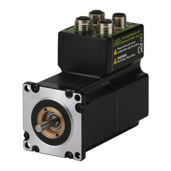
All the Quickstep motors are available as a fully programmable product with a wide range of features also covering a simple pulse and direction interface or Ethernet options. Examples of motors and stand alone electronics. JVL Industri Elektronik A/S - User Manual - Integrated Stepper Motors MIS17x, 23x, 34x, 43x... -
Page 6: Feature Overview
5V serial and • Wireless options: WiFi, Bluetooth and RS485 interface for set up and program- Zigbee. ming. • MODBUS interface. • 9.6kbit/sec. to 1Mb/sec. communication. JVL Industri Elektronik A/S - User Manual - Integrated Stepper Motors MIS17x, 23x, 34x, 43x... - Page 7 • Protection class IP42 and higher. • Hollow shaft. • Integrated ball screw or spindle for linear movement. • Custom made design for special applications JVL Industri Elektronik A/S - User Manual - Integrated Stepper Motors MIS17x, 23x, 34x, 43x...
- Page 8 Feature overview 1.1.1 Block diagram, Positioning/Speed Control JVL Industri Elektronik A/S - User Manual - Integrated Stepper Motors MIS17x, 23x, 34x, 43x...
-
Page 9: General Description
Torque (Oz-In) 100.0 14161 30.0 4248 MIS43x 20.0 2832 MIS34x 10.0 1416 708.1 MIS23x 141.6 MIS17x 70.81 TT2551-01GB 14.16 NEMA17 NEMA23 NEMA34 NEMA43 Flange size JVL Industri Elektronik A/S - User Manual - Integrated Stepper Motors MIS17x, 23x, 34x, 43x... - Page 10 “IN1” and “IN2”.The gear ratio can be set to a large ratio by using register 14 (GEAR1) and register 15 (GEAR2). CSP Mode Cyclic Synchronous Position mode (Ethernet only) JVL Industri Elektronik A/S - User Manual - Integrated Stepper Motors MIS17x, 23x, 34x, 43x...
-
Page 11: Hardware
Hardware The following pages explains how the I/O, Power supply, Interface etc. can be connected and used. JVL Industri Elektronik A/S - User Manual - Integrated Stepper Motors MIS17x, 23x, 34x, 43x... -
Page 12: Power Supply
- but if you need full safety please use the optional STO function which is available for all MIS and MIL motors. See also STO - Safe Torque Off, page 58. JVL Industri Elektronik A/S - User Manual - Integrated Stepper Motors MIS17x, 23x, 34x, 43x... - Page 13 Fuse dimensioning : See Dimensioning power supply and pre-fuse - MIS23x/MIL23x motors, page 17 or Dimensioning power supply and pre-fuse - MIS34x/MIL34x motors, page 18 JVL Industri Elektronik A/S - User Manual - Integrated Stepper Motors MIS17x, 23x, 34x, 43x...
- Page 14 M12 connectors is connected to the chassis/housing and thereby to the P- (GND/Common). The illustration below shows how to make a good power and earth connection of the MIS motor. JVL Industri Elektronik A/S - User Manual - Integrated Stepper Motors MIS17x, 23x, 34x, 43x...
- Page 15 Add the load current(s) to the current shown above. If the motor is equipped with an internal electromechani- cal brake this must also be added to the current consumption. JVL Industri Elektronik A/S - User Manual - Integrated Stepper Motors MIS17x, 23x, 34x, 43x...
- Page 16 ** =Not recommended for new designs. See also the appendix Power Supplies, page 341 which shows the standard power sup- plies that JVL offers. JVL Industri Elektronik A/S - User Manual - Integrated Stepper Motors MIS17x, 23x, 34x, 43x...
- Page 17 ** = Not recommended for new designs. See also the appendix Power Supplies, page 341 which shows the standard power sup- plies that JVL offers. JVL Industri Elektronik A/S - User Manual - Integrated Stepper Motors MIS17x, 23x, 34x, 43x...
- Page 18 ** = Not recommended for new designs. See also the appendix Power Supplies, page 341 which shows the standard power sup- plies that JVL offers. JVL Industri Elektronik A/S - User Manual - Integrated Stepper Motors MIS17x, 23x, 34x, 43x...
- Page 19 3. Make sure the motor is properly connected to a solid protective earth. 4. The surounding ambient temperature must maximum be 40’C. Notice that only the MIS34x family is UL recognized under UL file no: E254947 JVL Industri Elektronik A/S - User Manual - Integrated Stepper Motors MIS17x, 23x, 34x, 43x...
- Page 20 Below an example showing the torque curve for the MIS232S As seen the torque and power stay high up to much higher speeds when using 72VDC supply compared with 24 or 48VDC. JVL Industri Elektronik A/S - User Manual - Integrated Stepper Motors MIS17x, 23x, 34x, 43x...
-
Page 21: User Inputs
• Digital filter can be enabled for each input selectable from 0 to 100ms. If disabled (de- fault), the response time is 100μs. • Limit switch inputs JVL Industri Elektronik A/S - User Manual - Integrated Stepper Motors MIS17x, 23x, 34x, 43x... - Page 22 The value of the resistance used depends on the supply voltage. The following resistances are recommended: Supply Voltage Recommended Resistance R 5-12VDC 1kOhm / 0.25W 12-18VDC 2.2kOhm / 0.25W 18-24VDC 3.3kOhm / 0.25W 24-28VDC 4.7kOhm / 0.25W JVL Industri Elektronik A/S - User Manual - Integrated Stepper Motors MIS17x, 23x, 34x, 43x...
- Page 23 If “IOx Digital Filter enabled” is set, the specific input will use the digital filter according to the “Input filter time”. The remaining digital inputs will still be updating every 100 μs. JVL Industri Elektronik A/S - User Manual - Integrated Stepper Motors MIS17x, 23x, 34x, 43x...
- Page 24 See also Digital inputs - Usage., page 23 See also: Input_Filter_Cnt, page 216 JVL Industri Elektronik A/S - User Manual - Integrated Stepper Motors MIS17x, 23x, 34x, 43x...
-
Page 25: Analogue Inputs
Please notice: The number of available I/O terminals available may differ de- pending at which motor type and connector configuration you are using. Please consult the chapter Connector overview for the MIS motors, page 37 JVL Industri Elektronik A/S - User Manual - Integrated Stepper Motors MIS17x, 23x, 34x, 43x... - Page 26 Motor -> Filter setup, or the “Filter setup” button on the toolbar. Write the settings for each Input and click ‘OK’. The parameters can afterwards be “Saved in motor”. JVL Industri Elektronik A/S - User Manual - Integrated Stepper Motors MIS17x, 23x, 34x, 43x...
- Page 27 208 for filter parameters. 5.00V is equal to a value of 4095. R89-96 Analog Input The unfiltered voltage on inputs 1 to 8. 5.00V is equal to a value of 4095. JVL Industri Elektronik A/S - User Manual - Integrated Stepper Motors MIS17x, 23x, 34x, 43x...
- Page 28 A filter of 64 would simply copy the new sample to the rule, thus disabling the fil- tering. This completes the filtering of the analogue inputs. JVL Industri Elektronik A/S - User Manual - Integrated Stepper Motors MIS17x, 23x, 34x, 43x...
- Page 29 Confidence OK, no slope limitation needed, result = 100*(8/64)+96.171875*(56/64) ~= 96.65 units. Sample 81 = 100 Confidence OK, no slope limitation needed, result = 100*(8/64)+96.65*(56/64) ~= 97.07 units. JVL Industri Elektronik A/S - User Manual - Integrated Stepper Motors MIS17x, 23x, 34x, 43x...
- Page 30 99.65, 99.70, 99.74, 99.77, 99.80, 99.82, 99.84, 99.86, 99.88, 99.90, 99.91, 99.92, 99.93, 99.94, 99.95, 99.95, 99.96, 99.96, 99.97, 99.97, 99.98, 99.98, 99.98, 99.98, 99.99, 99.99, 99.99, …….100.0 JVL Industri Elektronik A/S - User Manual - Integrated Stepper Motors MIS17x, 23x, 34x, 43x...
-
Page 31: User Outputs
• 350 mA output current per channel even with all channels fully loaded at the same time. • Internal ground clamp diodes to protect when inductive load is driven. JVL Industri Elektronik A/S - User Manual - Integrated Stepper Motors MIS17x, 23x, 34x, 43x... - Page 32 If one or more outputs are short circuited, MacTalk will show Error “Output Driver” and Bit 2 will be set in Err_Bits. See also Err_Bits, page 201. JVL Industri Elektronik A/S - User Manual - Integrated Stepper Motors MIS17x, 23x, 34x, 43x...
-
Page 33: Serial Interfaces Overview
Please notice: The number of available I/O terminals available may differ de- pending at which motor type and connector configuration you are using. Please consult the chapter Connector overview for the MIS motors, page 37 JVL Industri Elektronik A/S - User Manual - Integrated Stepper Motors MIS17x, 23x, 34x, 43x... -
Page 34: Rs485 Interface
*** Each unit connected must be setup with an address via The MacTalk program. Baud rate = 19200 If only one unit is connected no address is needed. Stop bit = 1 Parity = None JVL Industri Elektronik A/S - User Manual - Integrated Stepper Motors MIS17x, 23x, 34x, 43x... -
Page 35: Emc Considerations
If the last motor has no connection cable, a connector with a resistor soldered between the A- and B+ pins should be used. JVL Industri Elektronik A/S - User Manual - Integrated Stepper Motors MIS17x, 23x, 34x, 43x... - Page 36 If a cable carries only RS-485 or only digital I/O, this simple and inexpensive form of shielding is recommended. JVL Industri Elektronik A/S - User Manual - Integrated Stepper Motors MIS17x, 23x, 34x, 43x...
-
Page 37: How To Connect A Mis Motor
MIS family members with radial standard connectors. 5 pin Female 4 pin Female PWR (CN1) 5 pin Male 8 pin Female 12 pin Female 8 pin Male 17 pin Female TT2323-01GB JVL Industri Elektronik A/S - User Manual - Integrated Stepper Motors MIS17x, 23x, 34x, 43x... - Page 38 * Note: P+ and P- are each available at 2 terminals. Make sure that both terminals are connected in order to split the supply current in 2 terminals and thereby avoid an overload of the connector. (Continued next page) JVL Industri Elektronik A/S - User Manual - Integrated Stepper Motors MIS17x, 23x, 34x, 43x...
- Page 39 1, 2, 3 and 4 are all fully independently isolated from each other. Group 1 correspond to the housing of the motor which may also be connected to earth via the DC or AC input supply. JVL Industri Elektronik A/S - User Manual - Integrated Stepper Motors MIS17x, 23x, 34x, 43x...
- Page 40 Protection caps. Optional if connector is not used to protect from dust / liquids. IP67 protection cap for M12 WI1000-M12FCAP1 female connector. IP67 protection cap for M12 WI1000-M12MCAP1 male connector. JVL Industri Elektronik A/S - User Manual - Integrated Stepper Motors MIS17x, 23x, 34x, 43x...
- Page 41 * Note: P+ and P- are each available at 2 terminals. Make sure that both terminals are connected in order to split the supply current in 2 terminals and thereby avoid an overload of the connector. (Continued next page) JVL Industri Elektronik A/S - User Manual - Integrated Stepper Motors MIS17x, 23x, 34x, 43x...
- Page 42 1, 2, 3 and 4 are all fully independently isolated from each other. Group 1 correspond to the housing of the motor which may also be connected to earth via the DC or AC input supply. JVL Industri Elektronik A/S - User Manual - Integrated Stepper Motors MIS17x, 23x, 34x, 43x...
- Page 43 Protection caps. Optional if connector is not used to protect from dust / liquids. IP67 protection cap for M12 WI1000-M12FCAP1 female connector. IP67 protection cap for M12 WI1000-M12MCAP1 male connector. JVL Industri Elektronik A/S - User Manual - Integrated Stepper Motors MIS17x, 23x, 34x, 43x...
- Page 44 * Note: P+ and P- are each available at 2 terminals. Make sure that both terminals are connected in order to split the supply current in 2 terminals and thereby avoid an overload of the connector. (Continued next page) JVL Industri Elektronik A/S - User Manual - Integrated Stepper Motors MIS17x, 23x, 34x, 43x...
- Page 45 1, 2, 3 and 4 are all fully independently isolated from each other. Group 1 correspond to the housing of the motor which may also be connected to earth via the DC or AC input supply. JVL Industri Elektronik A/S - User Manual - Integrated Stepper Motors MIS17x, 23x, 34x, 43x...
- Page 46 Protection caps. Optional if connector is not used to protect from dust / liquids. IP67 protection cap for M12 WI1000-M12FCAP1 female connector. IP67 protection cap for M12 WI1000-M12MCAP1 male connector. JVL Industri Elektronik A/S - User Manual - Integrated Stepper Motors MIS17x, 23x, 34x, 43x...
- Page 47 * Note: P+ and P- are each available at 2 terminals. Make sure that both terminals are connected in order to split the supply current in 2 terminals and thereby avoid an overload of the connector. (Continued next page) JVL Industri Elektronik A/S - User Manual - Integrated Stepper Motors MIS17x, 23x, 34x, 43x...
- Page 48 1, 2, 3 and 4 are all fully independently isolated from each other. Group 1 correspond to the housing of the motor which may also be connected to earth via the DC or AC input supply. JVL Industri Elektronik A/S - User Manual - Integrated Stepper Motors MIS17x, 23x, 34x, 43x...
- Page 49 Protection caps. Optional if connector is not used to protect from dust / liquids. IP67 protection cap for M12 WI1000-M12FCAP1 female connector. IP67 protection cap for M12 WI1000-M12MCAP1 male connector. JVL Industri Elektronik A/S - User Manual - Integrated Stepper Motors MIS17x, 23x, 34x, 43x...
- Page 50 EITHER the “BYPASS” OR the “COM” connector. Not both. 36.0mm [1.42 inch] 54.0mm [2.126 inch] = Mounting holes 5.0mm [0.197inch] Ø4x8mm [Ø0.16x0.32inch] Ø4/8mm [Ø0.16/0.32inch] 77.0mm [3.031inch] 112.0mm [4.409inch] 118.0mm [4.646inch] TT3088-01GB JVL Industri Elektronik A/S - User Manual - Integrated Stepper Motors MIS17x, 23x, 34x, 43x...
- Page 51 PA0190 is cable WI1000-M12F8TxxN is used with the used with the MAC00-Ex41 MIS34x motors Ethernet modules. connection 8 Pin Female cable WI1000-M12F8TxxN JVL Industri Elektronik A/S - User Manual - Integrated Stepper Motors MIS17x, 23x, 34x, 43x...
- Page 52 How to connect a MIS motor Diagram of the internal details in the PA0190 Junction Box. TT3090-01GB JVL Industri Elektronik A/S - User Manual - Integrated Stepper Motors MIS17x, 23x, 34x, 43x...
-
Page 53: Led Indicators Basic Motor
L1 to L3 can be configured to show the status of a almost any single bit from a user de- fined register. Please see FlexLEDSetup1, page 230 for the details. JVL Industri Elektronik A/S - User Manual - Integrated Stepper Motors MIS17x, 23x, 34x, 43x... -
Page 54: Led Indicators Using Canopen
L2 to L3 can be configured to show the status of a almost any single bit from a user de- fined register. Please see FlexLEDSetup1, page 230 for the details. JVL Industri Elektronik A/S - User Manual - Integrated Stepper Motors MIS17x, 23x, 34x, 43x... -
Page 55: Led Indicators Using Ethernet
Concerning LED indicators, software and protocol setup and usage please consult a sep- arate manual that can be found at www.jvl.dk using this link: www.jvl.dk The LED descriptions are in the chapters “Commissioning” for each protocol. JVL Industri Elektronik A/S - User Manual - Integrated Stepper Motors MIS17x, 23x, 34x, 43x... - Page 56 JVL Industri Elektronik A/S - User Manual - Integrated Stepper Motors MIS17x, 23x, 34x, 43x...
-
Page 57: Functional Safety
Functional Safety JVL Industri Elektronik A/S - User Manual - Integrated Stepper Motors MIS17x, 23x, 34x, 43x... -
Page 58: Sto - Safe Torque Off
Feedback type (if any) Controllertype = Includes STO. = Includes STO. = Includes STO. = Includes STO. S = Standard P = Potted TT2548-02GB JVL Industri Elektronik A/S - User Manual - Integrated Stepper Motors MIS17x, 23x, 34x, 43x... - Page 59 IEC61800-5-2 Safe Torque Off SRECS IEC62061 Safety related electrical control system SRP/CS ISO13849-1 Safety related parts of control systems PDS/SR IEC61800-5-2 Power drive system (safety related) JVL Industri Elektronik A/S - User Manual - Integrated Stepper Motors MIS17x, 23x, 34x, 43x...
-
Page 60: Safety
JVL Industri Elektronik A/S for service. The motor control electronics including the safety related parts must only be serviced and repaired by JVL Industri Elektronik A/S. Access to the inner parts of the motor will violate the guarantee. - Page 61 Time STO Function Activation TT2542-01GB JVL Industri Elektronik A/S - User Manual - Integrated Stepper Motors MIS17x, 23x, 34x, 43x...
- Page 62 If the motor is used outside the environmental limits given in this instruction the motor can not be expected to perform a safe stop when there is a demand on the STO-safety function. JVL Industri Elektronik A/S - User Manual - Integrated Stepper Motors MIS17x, 23x, 34x, 43x...
-
Page 63: Installation
A 100 mA fuse must be inserted in each channel. Use only the standard cable for the STO function: JVL stock no. WI1010-M08M4V05P. JVL Industri Elektronik A/S - User Manual - Integrated Stepper Motors MIS17x, 23x, 34x, 43x... - Page 64 Refer to STO commissioning test, page 70 for more information about how to test the safety function. JVL Industri Elektronik A/S - User Manual - Integrated Stepper Motors MIS17x, 23x, 34x, 43x...
-
Page 65: Commissioning
• A presence in the dangerous zone can be physically excluded when STO is not acti- vated. In particular, paragraph 6.3.3.2.5 of ISO 12100: 2010 must be observed. JVL Industri Elektronik A/S - User Manual - Integrated Stepper Motors MIS17x, 23x, 34x, 43x... - Page 66 The motor stays in the actual mode and the requested velocity will be set to 0 RPM. After the STO channels are ON, a velocity value (>0 RPM) must be written into the velocity register to get the motor moving again. JVL Industri Elektronik A/S - User Manual - Integrated Stepper Motors MIS17x, 23x, 34x, 43x...
- Page 67 Safe Torque off (internal error) Will only be set if the STO self-diagnostic circuit has detected an internal error. In this case, the motor must be returned to the manufacturer (JVL) for repair. This error can not be cleared. 3.4.7...
- Page 68 - Bit 29: STO - This bit will be set if one of the 2 STO inputs are off (not applied an voltage). Also STO is set if the STO_ACTION_ERROR bit is set. See also: Err_Bits, page 201 JVL Industri Elektronik A/S - User Manual - Integrated Stepper Motors MIS17x, 23x, 34x, 43x...
- Page 69 - Bit 31:STO_ACTION_V_ZERO The motor stays in the actual mode and the requested velocity will be set to 0 RPM. See also: Setup_Bits, page 213 JVL Industri Elektronik A/S - User Manual - Integrated Stepper Motors MIS17x, 23x, 34x, 43x...
- Page 70 8. Check that the motor runs at the defined velocity. Repeat the procedure with STO channel B. The commissioning test is successfully completed when all the given steps are passed. JVL Industri Elektronik A/S - User Manual - Integrated Stepper Motors MIS17x, 23x, 34x, 43x...
- Page 71 3.4.12 Disabling the STO function If the STO function is not needed the plug JVL type WI1010-M08M4SSTO must be in- serted in the STO connector at the motor. The reason for this external plug to disable the STO function is to obtain a high safety level and make sure that no misunderstandings will occur concerning whether the STO function is active or not.
- Page 72 The probability of failure of the safety func- tion due to a hardware fault has been estimated by JVL Industri Elektronik A/S as 1,38e- 10 per hour (IEC61508/IEC62061/IEC61800-5-2) or 4,29e-8 per hour (ISO13849), and assessed by the independent notified body TÜV NORD (pending).
- Page 73 Proof Test Interval T1 20 Years Mission time TM 20 Years Input to output response time Maximum 8 ms. Reaction time Response time (internal fault) Maximum 200 ms. JVL Industri Elektronik A/S - User Manual - Integrated Stepper Motors MIS17x, 23x, 34x, 43x...
- Page 74 • Reaction times are described in section STO function activation and indication re- sponse times in the table above. JVL Industri Elektronik A/S - User Manual - Integrated Stepper Motors MIS17x, 23x, 34x, 43x...
-
Page 75: Specifications And Certifications
Failure to maintain the specified ambient temperature can result in a failure of the safety function. 3.5.3 Certifications Certification Value TÜV Certified by TÜV NORD for Functional Safety: up to SIL CL3, according to IEC 61800‐5‐2, IEC 61508, and EN 62061; up to Performance Level PLe and Category 3, according to EN ISO 13849‐1; when used as described in this User Manual. JVL Industri Elektronik A/S - User Manual - Integrated Stepper Motors MIS17x, 23x, 34x, 43x... - Page 76 JVL Industri Elektronik A/S - User Manual - Integrated Stepper Motors MIS17x, 23x, 34x, 43x...
-
Page 77: Using Mactalk
Using MacTalk JVL Industri Elektronik A/S - User Manual - Integrated Stepper Motors MIS17x, 23x, 34x, 43x... -
Page 78: Using The Mactalk Software
MacTalk is normally connected through the RS485 interface but may also work on Ether- net (if the Ethernet option is present in the actual motor). JVL Industri Elektronik A/S - User Manual - Integrated Stepper Motors MIS17x, 23x, 34x, 43x... - Page 79 If the actual COM port is not known or the motor is setup with an address different from default the Auto Scan feature can help finding the motor(s). Auto Scan is also available when connecting with one of the Ethernet protocols (optional) JVL Industri Elektronik A/S - User Manual - Integrated Stepper Motors MIS17x, 23x, 34x, 43x...
- Page 80 If the user decides to go offline the following text box is presented. Pressing “OK” disconnects the motor from the PC-application and all data can be edited without any interruption in the motor. JVL Industri Elektronik A/S - User Manual - Integrated Stepper Motors MIS17x, 23x, 34x, 43x...
- Page 81 The following warning box is presented. Choosing “No” will immediately upload all motor data, pressing “yes” will save all data in the open file. JVL Industri Elektronik A/S - User Manual - Integrated Stepper Motors MIS17x, 23x, 34x, 43x...
- Page 82 I/O terminal. This can be very usefull in test situations when the motor is not installed in the final application with all I/O signals connected. JVL Industri Elektronik A/S - User Manual - Integrated Stepper Motors MIS17x, 23x, 34x, 43x...
- Page 83 Otherwise they only update at motor reset or power up. When relative moves are made using the MOVE command it uses the Position 1 (P1) reg- ister. JVL Industri Elektronik A/S - User Manual - Integrated Stepper Motors MIS17x, 23x, 34x, 43x...
- Page 84 This screen is used for adjusting the Zero search sensor to the correct position when us- ing the index pulse of an encoder. The index pulse should be in the green area. If not, the sensor has to be adjusted. JVL Industri Elektronik A/S - User Manual - Integrated Stepper Motors MIS17x, 23x, 34x, 43x...
- Page 85 The Setup has to be selected to set up the Scope function correctly before use. Most reg- isters in the MIS motors can be selected for viewing, different trigger functions can be selected, saving and loading scope pictures is possible, etc. JVL Industri Elektronik A/S - User Manual - Integrated Stepper Motors MIS17x, 23x, 34x, 43x...
-
Page 86: How To Update Mactalk
After MacTalk have restarted the version number of the new MacTalk can be observed in the top of the screen. The complete update is finished !. TT2342-02GB JVL Industri Elektronik A/S - User Manual - Integrated Stepper Motors MIS17x, 23x, 34x, 43x... -
Page 87: How To Update The Motor Firmware
Hint!: Some older products may not start after pushing the “start” button showed above. If this is the case simply switch off power wait 5 seconds and reapply power. The update should now start. JVL Industri Elektronik A/S - User Manual - Integrated Stepper Motors MIS17x, 23x, 34x, 43x... -
Page 88: How To Update The Encoder Fw
Hint!: Some older products may not start after pushing the “start” button showed above. If this is the case simply switch off power wait 5 seconds and re-apply power. The update should now start. JVL Industri Elektronik A/S - User Manual - Integrated Stepper Motors MIS17x, 23x, 34x, 43x... -
Page 89: How To Get Sw/Hw Motor Info
How to get SW/HW motor info JVL Industri Elektronik A/S - User Manual - Integrated Stepper Motors MIS17x, 23x, 34x, 43x... - Page 90 How to get SW/HW motor info JVL Industri Elektronik A/S - User Manual - Integrated Stepper Motors MIS17x, 23x, 34x, 43x...
-
Page 91: Description Of Functions
Description of functions JVL Industri Elektronik A/S - User Manual - Integrated Stepper Motors MIS17x, 23x, 34x, 43x... -
Page 92: Setting Up The Motor Current
A typical setting of the Standby Current typically is 30-40% of the Running current. Normally the motor do not need to produce any significant torque during standby and therefore it makes sense to lower the standby current. JVL Industri Elektronik A/S - User Manual - Integrated Stepper Motors MIS17x, 23x, 34x, 43x... - Page 93 See also Run_Current, page 192 for information about Running Current and Standby_Cur- rent, page 193 for information about Standby Current. JVL Industri Elektronik A/S - User Manual - Integrated Stepper Motors MIS17x, 23x, 34x, 43x...
-
Page 94: Auto Correction
The Auto correction feature is not recommended to use if the motor also has enabled the closed loop regulation. JVL Industri Elektronik A/S - User Manual - Integrated Stepper Motors MIS17x, 23x, 34x, 43x... - Page 95 Update the In Physical Position bit continuously Defines if the In Physical Position bit is updated continuously or only after the motor has stopped (default) JVL Industri Elektronik A/S - User Manual - Integrated Stepper Motors MIS17x, 23x, 34x, 43x...
- Page 96 Selects how close the internal encoder position must be to the target Position (P_SOLL) to set the InPhysical-Position status bit and prevent further AutoCorrection. See also: IN_POSITION_WINDOW, page 200 JVL Industri Elektronik A/S - User Manual - Integrated Stepper Motors MIS17x, 23x, 34x, 43x...
- Page 97 Bit 2: In Physical Position If set the motor position is physically within the In_Physical_Position_Window See also: Status bits, page 198 JVL Industri Elektronik A/S - User Manual - Integrated Stepper Motors MIS17x, 23x, 34x, 43x...
-
Page 98: Closed Loop Operation
"InTargetPosition" bit, which means that it will tell if the en- coder position and P_SOLL are within the "in position window". JVL Industri Elektronik A/S - User Manual - Integrated Stepper Motors MIS17x, 23x, 34x, 43x... - Page 99 A too high acceleration has been set. The motor cannot accelerate the load fast enough and therefore a follow error will be incremented until the motor is able to maintain the right speed. JVL Industri Elektronik A/S - User Manual - Integrated Stepper Motors MIS17x, 23x, 34x, 43x...
- Page 100 “Running current”. The motor can never run with a higher RMS current than the one specified in the “Running current” register, and the algorithm decreases the actual running current according to the follow error. JVL Industri Elektronik A/S - User Manual - Integrated Stepper Motors MIS17x, 23x, 34x, 43x...
- Page 101 TT2370-01GB Running current can be set here Standby current and Standby time is not used when current control and closed loop is enabled. JVL Industri Elektronik A/S - User Manual - Integrated Stepper Motors MIS17x, 23x, 34x, 43x...
- Page 102 As illustrated on the figure, the slope of the current increase and decrease are asymmet- rical. This is to stabilize the current control. JVL Industri Elektronik A/S - User Manual - Integrated Stepper Motors MIS17x, 23x, 34x, 43x...
- Page 103 The default for “Allowable overspeed...” is 0% which means that the maximum speed will never exceed the “Max velocity” setting. The default for “Follow error before overspeed” is 5000 counts. JVL Industri Elektronik A/S - User Manual - Integrated Stepper Motors MIS17x, 23x, 34x, 43x...
- Page 104 The “Actual torque” is defined from how many percentage of the “Running current” that is used. JVL Industri Elektronik A/S - User Manual - Integrated Stepper Motors MIS17x, 23x, 34x, 43x...
- Page 105 The acceleration/deceleration ramp to use. See also: A_SOLL, page 192 RUN_CURRENT The maximum motor current is setup in this regis- ter. See also: Run_Current, page 192 JVL Industri Elektronik A/S - User Manual - Integrated Stepper Motors MIS17x, 23x, 34x, 43x...
- Page 106 Current increment rate (independent of velocity). See also: CUR_SCALE_INC, page 229 R219 CUR_SCALE_DEC Current decrement rate (at 0 RPM) See also: CUR_SCALE_DEC, page 229 Continued next page. JVL Industri Elektronik A/S - User Manual - Integrated Stepper Motors MIS17x, 23x, 34x, 43x...
- Page 107 * 2048 = 227 ms for the current to decrease from 100 % to 0 % at DEC_0 0 RPM and T * 2048 = 2,3 s at 3000 RPM. DEC_3000 JVL Industri Elektronik A/S - User Manual - Integrated Stepper Motors MIS17x, 23x, 34x, 43x...
-
Page 108: Absolute Position Back-Up
The parameters available and their function are as follows: Acceptance Count Acceptance Voltage Save Voltage Value of P_IST after power up P_IST=0 Absolute Single turn Encoder Absolute Multiturn Encoder JVL Industri Elektronik A/S - User Manual - Integrated Stepper Motors MIS17x, 23x, 34x, 43x... - Page 109 JVL Industri Elektronik A/S - User Manual - Integrated Stepper Motors MIS17x, 23x, 34x, 43x...
- Page 110 Acceptance Voltage, selects the voltage threshold that defines when the power supply is ready to use for erasing flash memory after power up. The scaling/unit is the same as reg- ister 141. JVL Industri Elektronik A/S - User Manual - Integrated Stepper Motors MIS17x, 23x, 34x, 43x...
- Page 111 All data storage done by the absolute position backup function can also be monitored in the event log - see also : Reading the Event log, page 168 JVL Industri Elektronik A/S - User Manual - Integrated Stepper Motors MIS17x, 23x, 34x, 43x...
-
Page 112: Multifunction I/O Setup
Address for the internal switch board/cross field setup. Following text describe specifically which values that must be written into register 222 and 223 to obtain various outputs from the motor. JVL Industri Elektronik A/S - User Manual - Integrated Stepper Motors MIS17x, 23x, 34x, 43x... - Page 113 2 and 3 are used for this setting, all other bits must not be changed. This table shows how the combo box in MacTalk is setting the bits: Bit 2 Bit 3 Setting None Quadrature Pulse/direction JVL Industri Elektronik A/S - User Manual - Integrated Stepper Motors MIS17x, 23x, 34x, 43x...
- Page 114 2 and 3 are used for this setting, all other bits must not be changed. This table shows how the combo box in MacTalk is setting the bits: Bit 2 Bit 3 Setting None Quadrature Pulse/direction JVL Industri Elektronik A/S - User Manual - Integrated Stepper Motors MIS17x, 23x, 34x, 43x...
-
Page 115: Dedicated Outputs
The signal can be copied to a physical output This selection is done in MacTalk or by setting a bit in register 137 (bit 8). See also Inpos_Mask, page 216. JVL Industri Elektronik A/S - User Manual - Integrated Stepper Motors MIS17x, 23x, 34x, 43x... - Page 116 Velocity, Gear, Zero search) and Passive mode (motor not powered). This selection is done in MacTalk or by setting a bit in register 179. See also the chapter: Electro Mechanical brake, page 136 JVL Industri Elektronik A/S - User Manual - Integrated Stepper Motors MIS17x, 23x, 34x, 43x...
-
Page 117: Ssi Encoder/Sensor Interface
2 commands setup the RS485 multifunction interface covering the 4 lines to the SSI de- vice for transmitting a clock and receiving data from the SSI device. TT2479-02GB JVL Industri Elektronik A/S - User Manual - Integrated Stepper Motors MIS17x, 23x, 34x, 43x... - Page 118 Please bear in mind that if the external SSI device is tracking the position of something that moves the value and thereby the deviation from one sample to the next can be significant. JVL Industri Elektronik A/S - User Manual - Integrated Stepper Motors MIS17x, 23x, 34x, 43x...
- Page 119 If counting direction has been changed - the zero set (clearing the position counter) must be done to make sure that position data is valid. We suggest performing the zero set when the encoder is stationary (no rotation). JVL Industri Elektronik A/S - User Manual - Integrated Stepper Motors MIS17x, 23x, 34x, 43x...
- Page 120 «Prepare time» (1µS * n) «Gray to Bin converter» Activator (Set to 1" for Gray to bin " TT2483-01GB Set to "0" for no conversion) JVL Industri Elektronik A/S - User Manual - Integrated Stepper Motors MIS17x, 23x, 34x, 43x...
- Page 121 After the last data bit has been sampled, the clock stays high. Se also Setup and operation of the SSI function when using MacTalk., page 117 where a sample program is shown. JVL Industri Elektronik A/S - User Manual - Integrated Stepper Motors MIS17x, 23x, 34x, 43x...
-
Page 122: Absolute Multi-Turn Encoder
1/50 shaft revolution corresponding to 7.2 mechanical degrees. JVL Industri Elektronik A/S - User Manual - Integrated Stepper Motors MIS17x, 23x, 34x, 43x... - Page 123 4. The encoder position and all other relevant position registers are now preset with the new value. No further action is needed. The motor will remember this change also during power off. JVL Industri Elektronik A/S - User Manual - Integrated Stepper Motors MIS17x, 23x, 34x, 43x...
- Page 124 When selected the in position ?ag will realtime indicate if the motor is within the position window compared to a perfect move. TT2338-02GB See also Position "Auto correction", page 94 JVL Industri Elektronik A/S - User Manual - Integrated Stepper Motors MIS17x, 23x, 34x, 43x...
- Page 125 Bit if it have been lost for some reason or need an update because a newer firmware have been released having additional features it described in details how to do in How to up- date the encoder FW, page JVL Industri Elektronik A/S - User Manual - Integrated Stepper Motors MIS17x, 23x, 34x, 43x...
- Page 126 Battery level when temp. = 40deg.(108F) Batt. Le Batt. Le Battery level when temp. = 85deg.(185F) 9 10 11 12 13 14 15 16 17 18 19 20 Years JVL Industri Elektronik A/S - User Manual - Integrated Stepper Motors MIS17x, 23x, 34x, 43x...
- Page 127 Q5 If the internal battery is empty how long time is the position then kept ? A5 The position data is not kept if the internal battery is empty. JVL Industri Elektronik A/S - User Manual - Integrated Stepper Motors MIS17x, 23x, 34x, 43x...
-
Page 128: Position Limits
Please use the general chapter I/O Setup tab, page 82 for setting up the active level, op- tional input filter etc. JVL Industri Elektronik A/S - User Manual - Integrated Stepper Motors MIS17x, 23x, 34x, 43x... - Page 129 Please notice that if the activated limit switch has caused an error then remember to clear the error register before the motor can be set back in normal operation. TT2472-01GB JVL Industri Elektronik A/S - User Manual - Integrated Stepper Motors MIS17x, 23x, 34x, 43x...
- Page 130 Position Limit Min. In velocity mode the speed will internally be set to 0 when passing Position Limit Min, causing the motor to decelerate and stop. JVL Industri Elektronik A/S - User Manual - Integrated Stepper Motors MIS17x, 23x, 34x, 43x...
- Page 131 TT2475-01GB For further information about the internal registers that are behind the fields in MacTalk see also: MIN_P_IST, page 199 and MAX_P_IST, page 200. JVL Industri Elektronik A/S - User Manual - Integrated Stepper Motors MIS17x, 23x, 34x, 43x...
- Page 132 This can cause damage if not handled correctly by external logic (a PLC for instance). , page 213 , bit 28. "Position limits without memory" is enabled in the Setup_Bits JVL Industri Elektronik A/S - User Manual - Integrated Stepper Motors MIS17x, 23x, 34x, 43x...
-
Page 133: Under Voltage Handling
P+ is removed. The velocity setting will stay at 0 also after P+ is re- applied. A velocity value (>0 RPM) must be written into the velocity register to get the motor moving again. Continued next page JVL Industri Elektronik A/S - User Manual - Integrated Stepper Motors MIS17x, 23x, 34x, 43x... - Page 134 The 3 options that define the behaviour of the motor when P+ bus voltage is lower than what is set in the “Min bus voltage” field can all be accessed from MacTalk as shown be- low. JVL Industri Elektronik A/S - User Manual - Integrated Stepper Motors MIS17x, 23x, 34x, 43x...
- Page 135 See also: Setup_Bits, page 213 If none of the above bits are set the motor will con- tinue to run when the main power (P+) is back. JVL Industri Elektronik A/S - User Manual - Integrated Stepper Motors MIS17x, 23x, 34x, 43x...
-
Page 136: Electro Mechanical Brake
MacTalk do not support setup of the external brake but an internal register is available for setting up the brake. Please refer to Access without MacTalk, page 138 JVL Industri Elektronik A/S - User Manual - Integrated Stepper Motors MIS17x, 23x, 34x, 43x... - Page 137 A field named “Disable brake” at the main tab in MacTalk makes it possible to disable the brake. In the status bar at the right side its also possible to see whether the brake is active or not. JVL Industri Elektronik A/S - User Manual - Integrated Stepper Motors MIS17x, 23x, 34x, 43x...
- Page 138 Defines which of the eight outputs that controls the brake. Bit 8-15: Brake_T_ON (ms) Brake turn on time Bit 16-23: Brake_T_OFF (ms) Brake turn off time See also: Status bits, page 198 JVL Industri Elektronik A/S - User Manual - Integrated Stepper Motors MIS17x, 23x, 34x, 43x...
-
Page 139: Turn Table Mode
The registers normally used for software position limits are used to define the Turn Table working range in Turn Table Mode operation. (Continued next page) JVL Industri Elektronik A/S - User Manual - Integrated Stepper Motors MIS17x, 23x, 34x, 43x... - Page 140 - Multiturn CW rotation (4). Values below working range minimum are limited to the minimum. - Multiturn CCW rotation (5). Values above working range maximum are limited to the maximum. JVL Industri Elektronik A/S - User Manual - Integrated Stepper Motors MIS17x, 23x, 34x, 43x...
- Page 141 After the setup is done please remember to save it in the permanent memory by pressing the Save in motor button. TT2563-01GB JVL Industri Elektronik A/S - User Manual - Integrated Stepper Motors MIS17x, 23x, 34x, 43x...
- Page 142 >5 Important: Please remember to save the setup in permanent memory (save in flash) be- fore the setup is applied and used by the motor. JVL Industri Elektronik A/S - User Manual - Integrated Stepper Motors MIS17x, 23x, 34x, 43x...
- Page 143 For H3 and H4 encoder: Gives the absolute multi turn position, (-2 ) - (2 )-1. Not corrected for the turn table. JVL Industri Elektronik A/S - User Manual - Integrated Stepper Motors MIS17x, 23x, 34x, 43x...
- Page 144 It is generally recommended to set the maximum velocity V_SOLL, to zero when exiting a JOG operation and update P_IST and P_SOLL to desired values before setting V_SOLL back to a non-zero value. JVL Industri Elektronik A/S - User Manual - Integrated Stepper Motors MIS17x, 23x, 34x, 43x...
-
Page 145: Modes
PLC. Cycle times down to 1 ms are supported and means that P_SOLL is updated once every ms. Please consult the Ethernet manual for details. JVL Industri Elektronik A/S - User Manual - Integrated Stepper Motors MIS17x, 23x, 34x, 43x... -
Page 146: Passive Mode
It should thus be possible to turn the motor shaft as no voltage is connected to the motor. If there is encoder feed-back, the encoder counter will always register the cor- rect position. JVL Industri Elektronik A/S - User Manual - Integrated Stepper Motors MIS17x, 23x, 34x, 43x... -
Page 147: Velocity Mode
This mode is typically used for simple tasks or for applications in which an overall unit, such as a PC-board or PLC, controls velocity and positioning. JVL Industri Elektronik A/S - User Manual - Integrated Stepper Motors MIS17x, 23x, 34x, 43x... -
Page 148: Positioning Mode
PC/PLC via the interface. This mode is also well suited for setting up and testing systems. The mode is also used when programming is done. JVL Industri Elektronik A/S - User Manual - Integrated Stepper Motors MIS17x, 23x, 34x, 43x... -
Page 149: Gear Mode
5 x 409600 = 2048000 instead. Notice that a very high ratio may cause unstable behaviour in the motor speed. JVL Industri Elektronik A/S - User Manual - Integrated Stepper Motors MIS17x, 23x, 34x, 43x... - Page 150 - Pulse/direction is typically used as format in stepper motor systems. A pulse signal is applied to one input and the direction to another input. TT2463-01GB JVL Industri Elektronik A/S - User Manual - Integrated Stepper Motors MIS17x, 23x, 34x, 43x...
- Page 151 To make this change, a small RxP program is required in addition to the settings in Signal formats supported., page 150 Signal formats supported: G0392-10DK Continued next page JVL Industri Elektronik A/S - User Manual - Integrated Stepper Motors MIS17x, 23x, 34x, 43x...
- Page 152 General guidelines concerning the I/O’s are given in the following chapters: User Inputs, page 21 or General, page 32. JVL Industri Elektronik A/S - User Manual - Integrated Stepper Motors MIS17x, 23x, 34x, 43x...
- Page 153 A or B channel to move CW TT2467-02GB to move CCW JVL Industri Elektronik A/S - User Manual - Integrated Stepper Motors MIS17x, 23x, 34x, 43x...
- Page 154 The motor calculate continuously «on the fly» the necessary deceleration length and starts decelerating according to the the setting in the acceleration register. The motor will reach target (80 counts) exactly without any overshoot. TT2468-01GB JVL Industri Elektronik A/S - User Manual - Integrated Stepper Motors MIS17x, 23x, 34x, 43x...
- Page 155 Same relation as during acceleration. The motor will reach target (80 counts) exactly without any overshoot or time delay compared to the master position. TT2469-01GB JVL Industri Elektronik A/S - User Manual - Integrated Stepper Motors MIS17x, 23x, 34x, 43x...
- Page 156 MIS motor revolution. register register 409600 409600 409600 409600 1000 1000 409600 1600 1600 409600 2000 2000 409600 409600 409600 409600 (Equal to the MISxxx resolution) JVL Industri Elektronik A/S - User Manual - Integrated Stepper Motors MIS17x, 23x, 34x, 43x...
-
Page 157: Zero Search Modes
Zero search torque is defined as the zero position. The following sections explain in detail the functionality of the 3 fundamental Zero search modes. JVL Industri Elektronik A/S - User Manual - Integrated Stepper Motors MIS17x, 23x, 34x, 43x... - Page 158 The inputs for Home, Negative Limit and Positive Limit are selected here. JVL Industri Elektronik A/S - User Manual - Integrated Stepper Motors MIS17x, 23x, 34x, 43x...
- Page 159 0 or the motor enters passive mode. ignore the reference switch input and use the actual position or index pulse as zero position before using the zero search position. JVL Industri Elektronik A/S - User Manual - Integrated Stepper Motors MIS17x, 23x, 34x, 43x...
- Page 160 Hint: Make sure the acceleration/deceleration is set to an appropriate value which stops the motor when the Zero search switch is detected but before mechanical collision. JVL Industri Elektronik A/S - User Manual - Integrated Stepper Motors MIS17x, 23x, 34x, 43x...
- Page 161 • To improve the repeatability precision of the zero point make sure that the mechan- ical “collision” point is as stiff and well-defined as possible. JVL Industri Elektronik A/S - User Manual - Integrated Stepper Motors MIS17x, 23x, 34x, 43x...
- Page 162 (position 0). started is set to the value specified in the Zero search complete. “Zero search position” register TT2171-02GB JVL Industri Elektronik A/S - User Manual - Integrated Stepper Motors MIS17x, 23x, 34x, 43x...
- Page 163 See also T_Home, page 203 R42 HOMEMODE MacTalk name: “Zero search mode” Selects the zero search type that should start on power up. See also Home mode, page 203 JVL Industri Elektronik A/S - User Manual - Integrated Stepper Motors MIS17x, 23x, 34x, 43x...
- Page 164 R136 INPUT_FILTER_CNT MacTalk name: “Input filter time” The number of milliseconds the filtered digital inputs must be stable before accepting a change. See also Input_Filter_Cnt, page 216 JVL Industri Elektronik A/S - User Manual - Integrated Stepper Motors MIS17x, 23x, 34x, 43x...
-
Page 165: Error Handling
Error Handling JVL Industri Elektronik A/S - User Manual - Integrated Stepper Motors MIS17x, 23x, 34x, 43x... -
Page 166: Setup Error Limits
This will avoid that the motor enter passive mode and make the motor power less. See also End-of Travel Limit Inputs, page 128 Enable position limits without memory Simple mode: Position limits without memory, page 132 JVL Industri Elektronik A/S - User Manual - Integrated Stepper Motors MIS17x, 23x, 34x, 43x... -
Page 167: Error Messages
For example will a temperature error not be possible to clear before the temperature is lower than what is accepted. The next pages describe every error including cause for the error and how to solve the error situation. JVL Industri Elektronik A/S - User Manual - Integrated Stepper Motors MIS17x, 23x, 34x, 43x... - Page 168 The motor do not have a real time clock so all time stamps are based on the active time where the motor has been powered also showed as “Up time”. JVL Industri Elektronik A/S - User Manual - Integrated Stepper Motors MIS17x, 23x, 34x, 43x...
- Page 169 Check that none of the wires are short-circuited. How to return to normal Reset the motor / Cycle the power operation Error bit / Firmware name Bit 2 JVL Industri Elektronik A/S - User Manual - Integrated Stepper Motors MIS17x, 23x, 34x, 43x...
- Page 170 How to return to normal Reset the motor, clear the error bit(s) in register 35 or cycle the power. operation Error bit / Firmware name Bit 4 JVL Industri Elektronik A/S - User Manual - Integrated Stepper Motors MIS17x, 23x, 34x, 43x...
- Page 171 • Let MacTalk finish the firmware update. • Try firmware updating again and follow the recommendations How to return to normal operation above. Error bit / Firmware name Bit 7 JVL Industri Elektronik A/S - User Manual - Integrated Stepper Motors MIS17x, 23x, 34x, 43x...
- Page 172 • Reset the position (special command 354 in register 24), clear How to return to normal operation the error bit(s) in register 35 or cycle the power. Error bit / Firmware name Bit 9 JVL Industri Elektronik A/S - User Manual - Integrated Stepper Motors MIS17x, 23x, 34x, 43x...
- Page 173 • Reset the motor, clear the error bit(s) in register 35 or cy- How to return to normal operation cle the power. Error bit / Firmware name Bit 11 JVL Industri Elektronik A/S - User Manual - Integrated Stepper Motors MIS17x, 23x, 34x, 43x...
- Page 174 How to return to normal operation “Load factory defaults” in MacTalk. • Cycle the power to the motor. Error bit / Firmware name Bit 14 JVL Industri Elektronik A/S - User Manual - Integrated Stepper Motors MIS17x, 23x, 34x, 43x...
- Page 175 The motor is already in “normal operation” but the zero search operation have failed. Error bit / Firmware name Bit 16 See also Zero search modes, page 157 for further details. JVL Industri Elektronik A/S - User Manual - Integrated Stepper Motors MIS17x, 23x, 34x, 43x...
- Page 176 • If none of above - consult your JVL representative. • Cycle power How to return to normal • Make a software reset operation Error bit / Firmware name Bit 18 JVL Industri Elektronik A/S - User Manual - Integrated Stepper Motors MIS17x, 23x, 34x, 43x...
-
Page 177: Registers
Registers JVL Industri Elektronik A/S - User Manual - Integrated Stepper Motors MIS17x, 23x, 34x, 43x... -
Page 178: Introduction To Registers
Inputs, will never be read by the motor but always overwritten us- ing the latest sampled values. JVL Industri Elektronik A/S - User Manual - Integrated Stepper Motors MIS17x, 23x, 34x, 43x... -
Page 179: Internal Registers
‐ Special The current status of the digital inputs. “Status bar” OUTPUTS 32bit R/W ‐ Special The current status of the digital outputs, can be written to “Status bar” change the outputs. FLWERR 32bit R ‐ Steps When the encoder option is installed this shows encoder Follow error (‐2 )‐(2 ‐ deviation from the calculated position (P_IST). Reserved (intended for 64‐bit FLWERR hi‐word) JVL Industri Elektronik A/S - User Manual - Integrated Stepper Motors MIS17x, 23x, 34x, 43x... - Page 180 IN_POSITION_WINDOW 32bit R/W 32‐ 20000 Steps Selects how close the internal encoder position In position 0‐(2 must be to P_SOLL to set the InPhysical‐ window Position status bit and prevent further AutoCorrection. IN_POSITION_COUNT 32bit R/W 0‐100 Counts The number of times to attempt Max. number of AutoCorrection. A value of zero disables retries AutoCorrection. JVL Industri Elektronik A/S - User Manual - Integrated Stepper Motors MIS17x, 23x, 34x, 43x...
- Page 181 EXTENCODER 32bit R Counts The value from an external encoder, eg. SSI. SSI Encoder (‐2 )‐(2 ‐1) value FlexReg 32bit R ‐ ‐ A mix of 16 bits from different registers. The user can set this up. 49‐ 32bit R/W Steps 8 position registers (odd numbered registers) Position n (Pn) (‐2 )‐(2 ‐1) JVL Industri Elektronik A/S - User Manual - Integrated Stepper Motors MIS17x, 23x, 34x, 43x...
- Page 182 SSI_Setup1 32bit R/W ‐ ‐ Special SSI setup bits: SSI Encoder setup Bit 0‐4: No. of data bits Bit 5‐7: No. of samples Bit 8‐15: SSI clk. frequency Bit 16‐28: Max. sample deviation Bit 29‐31: Read retries SettlingTime 32bit R/W 0‐32676 Number of milliseconds to wait after an AutoCorrection Settling time attempt before testing for the position being within the between retries target window. JVL Industri Elektronik A/S - User Manual - Integrated Stepper Motors MIS17x, 23x, 34x, 43x...
- Page 183 Bit 6: In phys. Position update continuously Bit 10: Startup: Transfer single turn position to 2‐3: 0 = Disabled, 1 = P_IST Quadrature, 2 = Puls/ Bit 11: Startup: Transfer multi turn position to direction P_IST Bit 12: Startup: Keep External Encoder 17: No error if position Bit 13: Startup: Keep SSI Value limit is detected Bit 14: CANopen: Beckhoff mode Bit 15: Disable internal encoder Bit 16: External Encoder counting direction Bit 17: Disable position limit error Bit 19: Disable brake (int./ext.) temporarily Bit 20: Disable SSI encoder error Bit 21: Low bus voltage ‐> Error Bit 22: Low bus voltage ‐> Passive Bit 23: Low bus voltage ‐> 0 RPM Bit 24: Enable closed loop Bit 25: Enable closed loop current control Bit 28: Position limits without memory JVL Industri Elektronik A/S - User Manual - Integrated Stepper Motors MIS17x, 23x, 34x, 43x...
- Page 184 GROUP_ID 32bit R/W 0‐255 ‐ The group id of the motor – used for the Group Id GroupWrite telegram on the MacTalk protocol. GROUP_SEQ 32bit R 0‐255 ‐ ‐ The last received group write sequence – part of the MacTalk serial protocol. MY_ADDR 32bit R/W 0‐254 ‐ The motor address. Used on the MacTalk serial Motor address protocol. JVL Industri Elektronik A/S - User Manual - Integrated Stepper Motors MIS17x, 23x, 34x, 43x...
- Page 185 32bit R ‐ Tells which type of module is connected to the Dedicated internal 1Mbit/s Modbus channel. 0 = No module 0x34 = EthernetIP 0x35 = EtherCAT 0x36 = PowerLink 0x37 = Profinet 0x38 = Modbus/TCP EXT_ 32bit R/W ‐ Counts This register counts the external encoder. External (‐2 )‐(2 ‐ ENCODER encoder Reserved (intended for 64‐bit EXT_ENCODER hi‐word) JVL Industri Elektronik A/S - User Manual - Integrated Stepper Motors MIS17x, 23x, 34x, 43x...
- Page 186 (‐2 )‐(2 ‐1) Reserved ActualVelocity 32bit ‐ Object 606C subindex 0 (‐2 )‐(2 ‐1) Reserved Digital‐Outputs 32bit 0‐65535 ‐ Object 60FE subindex 1 (Low 16bit) Reserved DigitalInput 32bit 0‐65535 ‐ Object 60FD subindex 1 (Low 16bit) JVL Industri Elektronik A/S - User Manual - Integrated Stepper Motors MIS17x, 23x, 34x, 43x...
- Page 187 The actual cyclic setup from the Ethernet module. Bit 0‐15: Cycle period (us) Bit 16‐31: Sync0 offset in percent. EX_CRC_ERR 32bit R Counts CRC error counter of the internal communication between controller and Ethernet module. V_HOME_CRAWL 32bit R/W 0‐300,000 0.01 In Zero Search type 2, the “crawl” velocity is Zero search crawl V_HOME/64 by default. If register 242 is !=0, a user velocity defined velocity is used. V_HOME_TIMEOUT 32bit R/W If 0, the Zero Search time out is 60000 ms. Else the Zero search time value in this register is used. JVL Industri Elektronik A/S - User Manual - Integrated Stepper Motors MIS17x, 23x, 34x, 43x...
- Page 188 32bit R ‐ °C/ Like register 26 but the measured temperature is in Temperature 1000 full resolution and presented in degree celcius x 1000. LOWBUSCVI_CNT 32bit R/W Counts Number of times in a row the voltage can be too low before error is set. Time between each measurement = 100 us. V_ENCODER 32bit R ‐300,000‐ ‐ 0.01 The actual internal encoder velocity. Internal encoder 300,000 velocity JVL Industri Elektronik A/S - User Manual - Integrated Stepper Motors MIS17x, 23x, 34x, 43x...
- Page 189 Bit 14 to 23 indicate the overall motor type. For specific motor type see also the register Motor type, page 220 Detailed description of the individual bits: JVL Industri Elektronik A/S - User Manual - Integrated Stepper Motors MIS17x, 23x, 34x, 43x...
- Page 190 Please note that if the motor needs to change direction, it will decelerate and stop, and the new A_SOLL and V_START will be active. JVL Industri Elektronik A/S - User Manual - Integrated Stepper Motors MIS17x, 23x, 34x, 43x...
- Page 191 The MISxxx motor family all have 409600 counts per motor revolution. Example: If P_SOLL = 0 and then P_SOLL is set to 409600, the motor moves one revolution forward. JVL Industri Elektronik A/S - User Manual - Integrated Stepper Motors MIS17x, 23x, 34x, 43x...
- Page 192 When a new value is written to the RUN_CURRENT register, the new motor current will be set instantly. Example: RUN_CURRENT = 100, will set the running current to 0.587 ARMS. JVL Industri Elektronik A/S - User Manual - Integrated Stepper Motors MIS17x, 23x, 34x, 43x...
- Page 193 If V_SOLL = 40000 (400 RPM) and a movement of -10000 steps is done, V_IST will be -40000 (400 RPM) during the move and when the move is complete V_IST will be 0. JVL Industri Elektronik A/S - User Manual - Integrated Stepper Motors MIS17x, 23x, 34x, 43x...
- Page 194 The value can be used internally by the AutoCorrec- tion system to retry a movement in position and gear modes. JVL Industri Elektronik A/S - User Manual - Integrated Stepper Motors MIS17x, 23x, 34x, 43x...
- Page 195 Description: The maximum allowed value in FLWERR before an error is triggered. If FLWERRMAX = 0, the error is disabled. See register 35 (Err_Bits, page 201) for a description of the error bit. JVL Industri Elektronik A/S - User Manual - Integrated Stepper Motors MIS17x, 23x, 34x, 43x...
- Page 196 Set P_SOLL = Position register 4 Set V_SOLL = Velocity register 4 111 (FastMac 15) Set A_SOLL = Acceleration register 4 Set Running current = Current register 4 JVL Industri Elektronik A/S - User Manual - Integrated Stepper Motors MIS17x, 23x, 34x, 43x...
- Page 197 (100000 write cycles) and can be permanent damaged if this number i exceeded. The primary commands that access (write) in the flash memory are: Command 268, 269 and 342. JVL Industri Elektronik A/S - User Manual - Integrated Stepper Motors MIS17x, 23x, 34x, 43x...
- Page 198 Bit 22: In target position if encoder position and P_SOLL are within the window. Bit 23: STO channel A status Bit 24: STO channel B status Bit 25-26: External memory size: 0 = 0 kbit, 1=4kbit, 2=64kbit JVL Industri Elektronik A/S - User Manual - Integrated Stepper Motors MIS17x, 23x, 34x, 43x...
- Page 199 The MIN_P_IST is also used when using the Turn Table Mode to define the lower posi- tion limit of the turn table. Please also see Turn Table Mode, page 139 for detailed description. JVL Industri Elektronik A/S - User Manual - Integrated Stepper Motors MIS17x, 23x, 34x, 43x...
- Page 200 Max. number of 32bit 0 - 100 Counts COUNT retries Description: The number of times to attempt AutoCorrection. A value of zero disables AutoCorrec- tion. JVL Industri Elektronik A/S - User Manual - Integrated Stepper Motors MIS17x, 23x, 34x, 43x...
- Page 201 Important Bit 27 - Functional safety related ! The STO_ALARM will only be set if the STO self-diagnostic circuit has detected an inter- nal error. In this case, the motor must be returned the manufacturer (JVL) for repair. In general If any of these bits are set, the motor is in a state of error, and will not move until all the errors have been cleared.
- Page 202 These are used for diagnostic purposes as well as handling position limit stops, also after the motor may have left the end position mechanically. JVL Industri Elektronik A/S - User Manual - Integrated Stepper Motors MIS17x, 23x, 34x, 43x...
- Page 203 A value of 13 will use sensor type 1, while a value of 14 will use sensor type 2. Select 0 (default) if no automatic zero search must be done after power up. JVL Industri Elektronik A/S - User Manual - Integrated Stepper Motors MIS17x, 23x, 34x, 43x...
- Page 204 Description: A register that can be set up to contain different bits from several registers. 16 bits Flexible Register setup are available. See also , page 297 . JVL Industri Elektronik A/S - User Manual - Integrated Stepper Motors MIS17x, 23x, 34x, 43x...
- Page 205 Running current in several different ways, either from the user program or via the serial interfaces. See also the sections on FastMac commands. They select the current in the motor windings used during movement. JVL Industri Elektronik A/S - User Manual - Integrated Stepper Motors MIS17x, 23x, 34x, 43x...
- Page 206 This value is the basis for the warnings and errors of Low Bus Voltage and Over Voltage. 8.2.47 Min_Busvol Name Size Access Range Default Unit MacTalk name MIN_BUSVOL 32bit 0-4095 26.67 mV Min Bus Voltage Description: Trigger point for under-voltage JVL Industri Elektronik A/S - User Manual - Integrated Stepper Motors MIS17x, 23x, 34x, 43x...
- Page 207 If a new raw sample value is less than the value in this register, it is simply discarded and the filtered input value in registers 81-88 will not change. A value of zero in this register will effectively disable the minimum confidence check. JVL Industri Elektronik A/S - User Manual - Integrated Stepper Motors MIS17x, 23x, 34x, 43x...
- Page 208 The slope errors will be set if more than half of the samples within the last second were slope limited. JVL Industri Elektronik A/S - User Manual - Integrated Stepper Motors MIS17x, 23x, 34x, 43x...
- Page 209 SSI clock frequency in units of 10 kHz Bit 16-28: Max. sample deviation between each sample Bit 29-31: Read retries See also: SSI encoder/sensor interface, page 117 JVL Industri Elektronik A/S - User Manual - Integrated Stepper Motors MIS17x, 23x, 34x, 43x...
- Page 210 112-115. This value must never be set larger than the value in the read-only register 119. Sampling will stop automatically after the specified number of samples has been taken. JVL Industri Elektronik A/S - User Manual - Integrated Stepper Motors MIS17x, 23x, 34x, 43x...
- Page 211 Zero search/home position was found during Zero Search. This is selected by bit 0, Use Index, in register 122. It requires that the internal encoder option is installed. JVL Industri Elektronik A/S - User Manual - Integrated Stepper Motors MIS17x, 23x, 34x, 43x...
- Page 212 Bit 2: Search for opposite side of sensor Bit 3: (reserved) Bit 4: Ignore switch (Used for searching only for index) Bit 5: Disable zero search time out JVL Industri Elektronik A/S - User Manual - Integrated Stepper Motors MIS17x, 23x, 34x, 43x...
- Page 213 The lowest eight bits in this register can be used to individually invert the active lev- el of the digital inputs. The highest eight bits are used to select the corresponding pin as an output. JVL Industri Elektronik A/S - User Manual - Integrated Stepper Motors MIS17x, 23x, 34x, 43x...
- Page 214 Exactly one bit must be set, and the IO pin must be configured in register 125 as an input. Example: If input 7 is to be used for the Negative Input Limit, write 26 = 64 to this register. JVL Industri Elektronik A/S - User Manual - Integrated Stepper Motors MIS17x, 23x, 34x, 43x...
- Page 215 Exactly one bit must be set, and the IO pin must be configured in register 125 as an input. Example: If input 2 is to be used for the Home Input, write 21 = 2 to this register. JVL Industri Elektronik A/S - User Manual - Integrated Stepper Motors MIS17x, 23x, 34x, 43x...
- Page 216 See register 35 (Err_Bits, page 201) for more information on errors. Example: If output “n” is to be used for the Error Output, write 2^ (n-1) to this register. JVL Industri Elektronik A/S - User Manual - Integrated Stepper Motors MIS17x, 23x, 34x, 43x...
- Page 217 The basic idea behind this register/function is to make sure that the startup is completed and the supply voltage is stable. JVL Industri Elektronik A/S - User Manual - Integrated Stepper Motors MIS17x, 23x, 34x, 43x...
- Page 218 The firmware will automatically update the baud rate after this value is changed over the serial interface (RS485) once the motor has finished transmitting all data bytes that are queued. JVL Industri Elektronik A/S - User Manual - Integrated Stepper Motors MIS17x, 23x, 34x, 43x...
- Page 219 Description: The motor address. Data communicated over the serial interface will only be accepted if the address byte in the command is either equal to this value or has the value 255, which means broadcast to all motors. JVL Industri Elektronik A/S - User Manual - Integrated Stepper Motors MIS17x, 23x, 34x, 43x...
- Page 220 Stepper motor linear MIL342x Stepper motor linear MIL343x Stepper motor linear MIL344x Stepper motor linear This value is read-only and is programmed into the motor during manufacturing. JVL Industri Elektronik A/S - User Manual - Integrated Stepper Motors MIS17x, 23x, 34x, 43x...
- Page 221 Bit 0-15: Max voltage on bus Bit 16-31: Full scale motor current in mARMS JVL Industri Elektronik A/S - User Manual - Integrated Stepper Motors MIS17x, 23x, 34x, 43x...
- Page 222 Description: This register contains information about what options are available. Bit 0-7 defines the options available in the hardware (or licensed). Bit 8-15 defines the options available in the firmware. Bit 0,8: CanOpen fieldbus Bit 1,9: DeviceNet fieldbus JVL Industri Elektronik A/S - User Manual - Integrated Stepper Motors MIS17x, 23x, 34x, 43x...
- Page 223 Size Access Range Default Unit MacTalk name EXT_ENCODER 32bit Counts External Encoder )-(2 Description: This register counts the external encoder input at the multifunction I/O. JVL Industri Elektronik A/S - User Manual - Integrated Stepper Motors MIS17x, 23x, 34x, 43x...
- Page 224 External Encoder 32bit )-(2 _VEL 16ms Velocity Description: This register is updated with the velocity of the external encoder input. The velocity is measured every 16ms. JVL Industri Elektronik A/S - User Manual - Integrated Stepper Motors MIS17x, 23x, 34x, 43x...
- Page 225 A filter cutoff frequency on 3 kHz is recommended in the entire velocity range from 0 to 3000 RPM. The cutoff frequency is controlled by bit 6. JVL Industri Elektronik A/S - User Manual - Integrated Stepper Motors MIS17x, 23x, 34x, 43x...
- Page 226 Bit 8-15: Brake_T_ON - Time from motor is stopped until brake is activated = 40 ms Bit 16-23: Brake_T_OFF - Time from the motor is activated until the brake is de-actived = 50 ms. JVL Industri Elektronik A/S - User Manual - Integrated Stepper Motors MIS17x, 23x, 34x, 43x...
- Page 227 Description: Closed loop: Minimum running current in closed loop with "Current control" enabled. 2047 = 100 % of RUN_CURRENT. See also Special settings, page 106. JVL Industri Elektronik A/S - User Manual - Integrated Stepper Motors MIS17x, 23x, 34x, 43x...
- Page 228 “Actual torque” in MacTalk. The actual torque will settle at its minimum value at the optimal KPHASE. The new KPHASE can be saved in flash and will then be used automatically after a reset. JVL Industri Elektronik A/S - User Manual - Integrated Stepper Motors MIS17x, 23x, 34x, 43x...
- Page 229 - Quadrature/pulse-direction step generation output This register controls the internal addressing for this setup. It is strongly recommended to use MacTalk as interface for the setup. JVL Industri Elektronik A/S - User Manual - Integrated Stepper Motors MIS17x, 23x, 34x, 43x...
- Page 230 L3 = “In position” bit from the Status register (25). Setup: Bit 0-8: Register for L3 Bit 9-13: Bit for L3 Bit 16-24: Register for L2 Bit 25-29: Bit for L2 JVL Industri Elektronik A/S - User Manual - Integrated Stepper Motors MIS17x, 23x, 34x, 43x...
- Page 231 Counts multiples of 409600 counts since power on. The value is added to the motor rev- olution counter in the Event log in order to keep the total amount of revolutions the mo- tor has run in its entire lifetime. JVL Industri Elektronik A/S - User Manual - Integrated Stepper Motors MIS17x, 23x, 34x, 43x...
- Page 232 0 to this register. The unit is milliseconds. If 0, the Zero Search time out is 60000 ms. Else the value in this register is used. JVL Industri Elektronik A/S - User Manual - Integrated Stepper Motors MIS17x, 23x, 34x, 43x...
- Page 233 MacTalk name TEMP_HIGHRES 32bit °C/1000 Temperature Description: Temperature measured inside the motor electronics. The measured temperature is presented in °C/1000 with higher resolution than register JVL Industri Elektronik A/S - User Manual - Integrated Stepper Motors MIS17x, 23x, 34x, 43x...
- Page 234 Access Range Default Unit MacTalk name -3,000.00 - Internal encoder V_ENCODER 32bit 0.01 RPM 3,000.00 velocity The actual velocity measured from the internal (H2/H4) encoder. JVL Industri Elektronik A/S - User Manual - Integrated Stepper Motors MIS17x, 23x, 34x, 43x...
-
Page 235: Building Sequential Programs
Building Sequential Programs JVL Industri Elektronik A/S - User Manual - Integrated Stepper Motors MIS17x, 23x, 34x, 43x... -
Page 236: Getting Started With Programming
Please note: When a program is made and stored the motor will always startup in po- sition mode. If this is not convinient insert a Mode = “passive” on first program line. JVL Industri Elektronik A/S - User Manual - Integrated Stepper Motors MIS17x, 23x, 34x, 43x... -
Page 237: Programming Main Window
Programming Main window The main window for creating a new program or editing a program is shown below: JVL Industri Elektronik A/S - User Manual - Integrated Stepper Motors MIS17x, 23x, 34x, 43x... -
Page 238: Programming Menu
Programming menu The menu found at the top of the main window gives access to the following options: JVL Industri Elektronik A/S - User Manual - Integrated Stepper Motors MIS17x, 23x, 34x, 43x... -
Page 239: How To Build A Program
Choose to wait until input 5 is high and press OK The command is inserted at the previous selected program line Continued TT0983GB JVL Industri Elektronik A/S - User Manual - Integrated Stepper Motors MIS17x, 23x, 34x, 43x... - Page 240 Press the “Transfer & Start” button. Now the program will be transfered and stored permanently in the module. The program will be executed immidiately Continued TT0984GB JVL Industri Elektronik A/S - User Manual - Integrated Stepper Motors MIS17x, 23x, 34x, 43x...
- Page 241 I/O setup etc. Everything is stored in a file with the extension .MAC . Later it can be opened and restored in the motor. TT0985GB JVL Industri Elektronik A/S - User Manual - Integrated Stepper Motors MIS17x, 23x, 34x, 43x...
-
Page 242: General Programming Hints
3. A program line can be edited by double-clicking on the command text. 4. When the cursor is placed on top of the command icon, an edit menu will be shown by right-clicking. JVL Industri Elektronik A/S - User Manual - Integrated Stepper Motors MIS17x, 23x, 34x, 43x... -
Page 243: Command Toolbox Description
5% is typically achieved by accessing the basic motor registers directly. The following gives a short description of all 18 command icons. JVL Industri Elektronik A/S - User Manual - Integrated Stepper Motors MIS17x, 23x, 34x, 43x... -
Page 244: Graphic Programming Command Reference
9.7.3 Move operations Icon: Function: The Move commands are very flexible, with five different operating modes. Each mode is described in its own section below. JVL Industri Elektronik A/S - User Manual - Integrated Stepper Motors MIS17x, 23x, 34x, 43x... - Page 245 If this option is not checked, the program will start the movement, then immediately start executing the next command. The motor will finish the movement on its own, unless given other instructions by the program. JVL Industri Elektronik A/S - User Manual - Integrated Stepper Motors MIS17x, 23x, 34x, 43x...
- Page 246 Avoid selecting the “Wait for in position” flag and use a loop after the move command which is looking at “in position flag” and “error” JVL Industri Elektronik A/S - User Manual - Integrated Stepper Motors MIS17x, 23x, 34x, 43x...
- Page 247 Register no. 49 (P1) is always overwritten by this command. This command always waits until the movement is finished, before proceeding to the next line in the program. JVL Industri Elektronik A/S - User Manual - Integrated Stepper Motors MIS17x, 23x, 34x, 43x...
- Page 248 If this option is not checked, the program will start the movement, then immediately start executing the next command. The motor will finish the movement on its own, unless given other instructions by the program. JVL Industri Elektronik A/S - User Manual - Integrated Stepper Motors MIS17x, 23x, 34x, 43x...
- Page 249 Register no. 49 (P1) is always overwritten by this command. This command always waits until the movement is finished before proceeding to the next line in the program. JVL Industri Elektronik A/S - User Manual - Integrated Stepper Motors MIS17x, 23x, 34x, 43x...
- Page 250 (in milliseconds) of a pulse to send out on that output. When setting multiple outputs, you can specify whether to set each output high, low, or leave it in its current state. JVL Industri Elektronik A/S - User Manual - Integrated Stepper Motors MIS17x, 23x, 34x, 43x...
- Page 251 After pressing the OK button, the dialogue will disappear, and the mouse cursor will change. The next program line that you click on will then become the destination of the jump command. JVL Industri Elektronik A/S - User Manual - Integrated Stepper Motors MIS17x, 23x, 34x, 43x...
- Page 252 After pressing the OK button, the dialogue will disappear, and the mouse cursor will change. The next program line that you click on will then become the destination of the jump command. JVL Industri Elektronik A/S - User Manual - Integrated Stepper Motors MIS17x, 23x, 34x, 43x...
- Page 253 (Falling Edge), or that the input transitions from low to high (Rising Edge). The input is tested with 30 microsecond intervals. JVL Industri Elektronik A/S - User Manual - Integrated Stepper Motors MIS17x, 23x, 34x, 43x...
- Page 254 If set to ‘Or’, only one input need match its test setting. Inputs that are set to ‘Don’t care’ are not tested. The inputs are tested with 30 microsecond intervals. JVL Industri Elektronik A/S - User Manual - Integrated Stepper Motors MIS17x, 23x, 34x, 43x...
- Page 255 After pressing the OK button, the dialogue will disappear and the mouse cursor will change. The next program line that you click on will then become the destination of the jump command. JVL Industri Elektronik A/S - User Manual - Integrated Stepper Motors MIS17x, 23x, 34x, 43x...
- Page 256 Saves the current position from register no. 10 (P_IST) to one of three locations in the user memory area. The saved position(s) can then be used whenever a position or distance is needed in a move command. JVL Industri Elektronik A/S - User Manual - Integrated Stepper Motors MIS17x, 23x, 34x, 43x...
- Page 257 For a detailed description of how to set up a zero search, refer to Zero search modes, page 157 JVL Industri Elektronik A/S - User Manual - Integrated Stepper Motors MIS17x, 23x, 34x, 43x...
- Page 258 In the example above, the value in register no. 65 (V1) will be written to register no. 5 (V_SOLL). Move operations will then take place at that velocity. JVL Industri Elektronik A/S - User Manual - Integrated Stepper Motors MIS17x, 23x, 34x, 43x...
- Page 259 If special needs arise that are not covered by the other commands, contact JVL for assistance. JVL Industri Elektronik A/S - User Manual - Integrated Stepper Motors MIS17x, 23x, 34x, 43x...
- Page 260 . If the result of a calculation to 2 gives a higher value than it will therefore becomes negative and similar if a calculationresult becomes lowe than the result becomes positive. JVL Industri Elektronik A/S - User Manual - Integrated Stepper Motors MIS17x, 23x, 34x, 43x...
- Page 261 A recognized register name will appear in the expression. An unrecognizable register name will appear as a zero. You can switch between the two methods of data entry at any time. JVL Industri Elektronik A/S - User Manual - Integrated Stepper Motors MIS17x, 23x, 34x, 43x...
- Page 262 32-bit wide, and both measure position in encoder counts. Such a comparison will always yield meaningful, predictable results. For other types of registers, see the relevant register sections. JVL Industri Elektronik A/S - User Manual - Integrated Stepper Motors MIS17x, 23x, 34x, 43x...
-
Page 263: Command Timing
Conditional jump (register) Save position Set position Send fastMAC command Binary command 1) The time for all move commands is shown without waiting for in position JVL Industri Elektronik A/S - User Manual - Integrated Stepper Motors MIS17x, 23x, 34x, 43x... -
Page 264: More About Program Timing
Note: In applications where program timing is critical, tests must be performed to ensure that timing is satisfactory when communication is running according to conditions used in production! JVL Industri Elektronik A/S - User Manual - Integrated Stepper Motors MIS17x, 23x, 34x, 43x... -
Page 265: Ethernet Protocols (Optional)
Concerning software and protocol setup and usage - please consult a separate manual that can be found at www.jvl.dk using this link: www.jvl.dk The litterature number is LB0056-xxGB (xx=version). JVL Industri Elektronik A/S - User Manual - Integrated Stepper Motors MIS17x, 23x, 34x, 43x... - Page 266 JVL Industri Elektronik A/S - User Manual - Integrated Stepper Motors MIS17x, 23x, 34x, 43x...
-
Page 267: Canopen (Optional)
Survey of objects which are used in the DSP-402 standard. See section 11.5.1 section 11.5.7. Section with more detailed explanations of the CANopen theory, particularly DS-301. section 11.7.1 section 11.7.7. JVL Industri Elektronik A/S - User Manual - Integrated Stepper Motors MIS17x, 23x, 34x, 43x... -
Page 268: General Information About Canopen
The de- vices are connected through a 2-wire bus cable with ground, and data is transmitted serially. JVL Industri Elektronik A/S - User Manual - Integrated Stepper Motors MIS17x, 23x, 34x, 43x... - Page 269 This characteristic means that important messages are transmitted with high priority even in exceptional situations, thereby ensuring proper functioning of a system even dur- ing phases of restricted transmission capacity. JVL Industri Elektronik A/S - User Manual - Integrated Stepper Motors MIS17x, 23x, 34x, 43x...
- Page 270 The two bit fields “Header” and “Data” form the simplified CANopen message. The 11- bit Header is also designated as the identifier or as the COB-ID (Communication Object identifier). JVL Industri Elektronik A/S - User Manual - Integrated Stepper Motors MIS17x, 23x, 34x, 43x...
- Page 271 11.1 General information about CANopen JVL uses the 11-bit format type CAN A, but not the 29-bit format type CAN B. The COB-ID carries out two tasks for the controller communications object. - Bus arbitration: Specification of transmission priorities. - Identification of communications objects.
-
Page 272: 11.2 Connection And Setup Of The Can Bus
For support of the PLC master, the PLC vendor is recommended. If you are using a PC as master, JVL provides some tools that can help when installing and using the MIS motors. - Page 273 The latest firmware for the MIS motors is available at JVL’s web-site under the menu downloads/firmware. In the site’s programs menu, the software CANopenExplorer is also available, but note that this is not a free-ware program. Please contact your JVL rep- resentative for further information.
- Page 274 See the general connection guide for connecting CAN bus to the MIS motors. How to connect a MIS motor, page 37 JVL Industri Elektronik A/S - User Manual - Integrated Stepper Motors MIS17x, 23x, 34x, 43x...
-
Page 275: Using Canopenexplorer
The CANopen module must be connected to a CAN bus, as shown in section 11.2.5. To set up the master, download the EDS file from the JVL web site (see section 11.2.2). This file contains all register set-up data for the MIS motors. - Page 276 Using CANopenExplorer TT1100GB 4: Select here on the +the manufacturer specific register. 5: Select thereafter the object 0x2012. Object 0x2012 contains the motor parameters. TT1101GB JVL Industri Elektronik A/S - User Manual - Integrated Stepper Motors MIS17x, 23x, 34x, 43x...
- Page 277 9: Click on the sub register 0x03, which is the register to choose the distance the motor will run. Press W on the keyboard, type 20000 in the window, and type OK. The val- ue 20000 is in Steps JVL Industri Elektronik A/S - User Manual - Integrated Stepper Motors MIS17x, 23x, 34x, 43x...
- Page 278 Double-clicking on a user SDO list will execute the operation, either reading or writing. The bus state can be changed using the NMT buttons, lower left, e.g. to Operational to enable PDOs. JVL Industri Elektronik A/S - User Manual - Integrated Stepper Motors MIS17x, 23x, 34x, 43x...
- Page 279 The close button exits the program after saving the list of user SDOs, which will be au- tomatically reloaded at the next program start. JVL Industri Elektronik A/S - User Manual - Integrated Stepper Motors MIS17x, 23x, 34x, 43x...
-
Page 280: Objects In The Ds301 Standard
VISIBLE er device 1008 JVL A/S STRING name Manufactur- VISIBLE er hardware 1009 STRING version Manufactur- VISIBLE er software 100A Example: Version x.x STRING version JVL Industri Elektronik A/S - User Manual - Integrated Stepper Motors MIS17x, 23x, 34x, 43x... - Page 281 After the unit has started up and there is communication be- tween the master and the slave, turn on the required error control mechanism in the communication objects, see DS301 specified Communications objects, page 280. JVL Industri Elektronik A/S - User Manual - Integrated Stepper Motors MIS17x, 23x, 34x, 43x...
- Page 282 1h, and the value range of this register is UNSIGNED32. The PDOs are enabled when bit 31 is 0, and is disabled when bit 31 is 1. JVL Industri Elektronik A/S - User Manual - Integrated Stepper Motors MIS17x, 23x, 34x, 43x...
- Page 283 • Remap to another object by writing to PDO Mapping Entry 1: 0x20140510. • Write 1 in Number of Entries. TT2494-01GB Please note: Sub 0x03 (Inhibit time) and 0x04 (Compatibility Entry) are not supported. JVL Industri Elektronik A/S - User Manual - Integrated Stepper Motors MIS17x, 23x, 34x, 43x...
- Page 284 This PDO can be used to update the position, velocity and acceleration. The data in the PDO is written directly to the position register and if the motor is in position mode, it will start moving to that position. JVL Industri Elektronik A/S - User Manual - Integrated Stepper Motors MIS17x, 23x, 34x, 43x...
- Page 285 Available Object 2014h, sub 19 Tables shown above are default mapping. The mapping can however also be changed dy- namically. See Dynamic Mapping, page 283 JVL Industri Elektronik A/S - User Manual - Integrated Stepper Motors MIS17x, 23x, 34x, 43x...
- Page 286 2014h, sub 91 2014h, sub 92 Tables shown above are default mapping. The mapping can however also be changed dy- namically. See Dynamic Mapping, page 283 JVL Industri Elektronik A/S - User Manual - Integrated Stepper Motors MIS17x, 23x, 34x, 43x...
- Page 287 Beckhoff mode PDO 1-4 is automatically enabled at power up. To setup and use the Beckhoff mode, enable the Beckhoff support from MacTalk and press the Save in flash -button. T T 2267GB JVL Industri Elektronik A/S - User Manual - Integrated Stepper Motors MIS17x, 23x, 34x, 43x...
- Page 288 Available Object 2014h, sub 19 Tables shown above are default mapping. The mapping can however also be changed dy- namically. See Dynamic Mapping, page 283 JVL Industri Elektronik A/S - User Manual - Integrated Stepper Motors MIS17x, 23x, 34x, 43x...
- Page 289 2014h, sub 95 2014h, sub 96 Transmit PDO 4: With this PDO the actual velocity can be read. Byte Data V_IST Available Object 2014h, sub 18 JVL Industri Elektronik A/S - User Manual - Integrated Stepper Motors MIS17x, 23x, 34x, 43x...
-
Page 290: 11.5 Objects Used In The Dsp-402 Standard
Please refer to this standard for details of the functions. The DSP-402 is only a standard proposal and might be changed in the future. JVL there- fore reserves the right to change future firmware versions to conform to new versions of the standard. - Page 291 6064 INTEGER32 Target_position 607A INTEGER32 Software_position_limit 607D UNSIGNED8 Software_position_limit_ 607D INTEGER32 Min_position_limit Software_position_limit_ 607D INTEGER32 Max_position_limit Max_motor_speed 6080 UNSIGNED32 Profile_velocity 6081 UNSIGNED32 Profile_acceleration 6083 UNSIGNED32 JVL Industri Elektronik A/S - User Manual - Integrated Stepper Motors MIS17x, 23x, 34x, 43x...
- Page 292 UNSIGNED32 Motor_revolutions Velocity_encoder_resolution 6090 UNSIGNED8 Velocity_encoder_resolution_ 6090 UNSIGNED32 Encoder_increments_per_second Velocity_encoder_resolution_ 6090 UNSIGNED32 Motor_revolutions_per_second Gear_ratio 6091 UNSIGNED8 Gear_ratio_Motor_revolutions 6091 UNSIGNED32 Gear_ratio_Shaft_revolutions 6091 UNSIGNED32 Feed_constant 6092 UNSIGNED8 JVL Industri Elektronik A/S - User Manual - Integrated Stepper Motors MIS17x, 23x, 34x, 43x...
- Page 293 Gear ratio - Motor revolutions 6091 subindex 2 Gear ratio - Shaft revolutions 6092 subindex 1 Feed constant - Feed 38956 6092 subindex 2 Feed constant - Shaft revolutions JVL Industri Elektronik A/S - User Manual - Integrated Stepper Motors MIS17x, 23x, 34x, 43x...
- Page 294 The parameters should be set as follows: Object Name Value 6097 subindex 1 Acceleration encoder factor - Numerator 6097 subindex 2 Acceleration encoder factor – Divisor JVL Industri Elektronik A/S - User Manual - Integrated Stepper Motors MIS17x, 23x, 34x, 43x...
- Page 295 Using this mode, different Zero Search sequences can be initiated. The standard Zero Search modes from 1-34 are supported. Before starting the Zero Search, the inputs must be configured properly using MacTalk or parameters 125,129,130,132. JVL Industri Elektronik A/S - User Manual - Integrated Stepper Motors MIS17x, 23x, 34x, 43x...
- Page 296 6061h Modes of operation display 6041h Status word 6064h Position actual value 6041h Status word 606Ch Velocity actual value 6041h Status word 60FDh Digital inputs JVL Industri Elektronik A/S - User Manual - Integrated Stepper Motors MIS17x, 23x, 34x, 43x...
-
Page 297: Flexible Register Setup
The setup can be done manually with SDO access or directly in MacRegIO. Please note: The function will only be activated if register 224 (FlexRegister bit 0 and 1) is set. JVL Industri Elektronik A/S - User Manual - Integrated Stepper Motors MIS17x, 23x, 34x, 43x... -
Page 298: More Details Of Canopen Theory
The communication Profile area contains the parameters for the communication profile on the CAN network. These entries are common to all devices. Index 2000-5FFF: The manufacturer-specific profile area, for truly manufacturer-specific functionality. JVL Industri Elektronik A/S - User Manual - Integrated Stepper Motors MIS17x, 23x, 34x, 43x... - Page 299 See the figure below: NMT Slave NMT Master COB-ID = 700h + Node-ID Indication Request TT1085GB One data byte is transmitted with value 0. JVL Industri Elektronik A/S - User Manual - Integrated Stepper Motors MIS17x, 23x, 34x, 43x...
- Page 300 MIS23x (SMC75) is the consumer and for Transmit PDOs, the producer. The following figure shows a Write PDO service: PDO Producer PDO Consumers L = 0..8 Request Indication Proces data TT1086GB JVL Industri Elektronik A/S - User Manual - Integrated Stepper Motors MIS17x, 23x, 34x, 43x...
- Page 301 This mechanism is called an expedited transfer. Download SDO protocol: The download SDO protocol is used to write the values of the object directory into the drive. JVL Industri Elektronik A/S - User Manual - Integrated Stepper Motors MIS17x, 23x, 34x, 43x...
- Page 302 [8-n,7] do not contain expedited set size is transfer by data transfer indicated the SDO CCS:Client command specified. SCS: Server commander specified. JVL Industri Elektronik A/S - User Manual - Integrated Stepper Motors MIS17x, 23x, 34x, 43x...
- Page 303 Attempt to write a read-only object 0602 0000h Object does not exist in the object dictionary 0604 0041h Object cannot be mapped to the PDO JVL Industri Elektronik A/S - User Manual - Integrated Stepper Motors MIS17x, 23x, 34x, 43x...
- Page 304 SYNC Producer SYNC Consumers Request Indication TT1091GB The SYNC does not carry any data (L=0). The identifier of the SYNC object is located at object 1005h. JVL Industri Elektronik A/S - User Manual - Integrated Stepper Motors MIS17x, 23x, 34x, 43x...
- Page 305 In the Pre-Operational state, the node cannot process any PDOs. However, it can be parameterized or operated via SDO. This means set point can also be entered. JVL Industri Elektronik A/S - User Manual - Integrated Stepper Motors MIS17x, 23x, 34x, 43x...
- Page 306 The Node Life Time is calculated from the product of the Guard Time and Life Time Fac- tor. This is the maximum time that the slave waits for an RTR telegram. The figure below shows a Node Guarding/Life Guarding protocol. JVL Industri Elektronik A/S - User Manual - Integrated Stepper Motors MIS17x, 23x, 34x, 43x...
- Page 307 The Heartbeat Consumer guards the reception of the Heartbeat within the Heartbeat Consumer time. If the Heartbeat is not received within the Heartbeat Consumer Time, a Heartbeat Event will be generated. JVL Industri Elektronik A/S - User Manual - Integrated Stepper Motors MIS17x, 23x, 34x, 43x...
- Page 308 After the module has started up and there is communication between the master and the slave, activate the required error control mechanism in the object Dictionary. See DS301 specified Communications objects, page 280. JVL Industri Elektronik A/S - User Manual - Integrated Stepper Motors MIS17x, 23x, 34x, 43x...
-
Page 309: Modbus Interface
Modbus interface JVL Industri Elektronik A/S - User Manual - Integrated Stepper Motors MIS17x, 23x, 34x, 43x... -
Page 310: Modbus
Contact JVL if more registers are needed in a single transfer. JVL recommends reading and writing as few 32-bit values as possible, normally 4 or max- imum 8 at a time. Whenever possible, split long commands into smaller commands. Also, only write the absolutely necessary values to the motor. - Page 311 Example to write P_SOLL (register 3) to motor with address 254, values in decimal: 254, 16, 0, 6, 0, 2, 4, bb, aa, dd, cc, NN, MM(NN and MM are the CRC-16 bytes) JVL Industri Elektronik A/S - User Manual - Integrated Stepper Motors MIS17x, 23x, 34x, 43x...
- Page 312 High byte, Low byte. Command: 254, 16, 156, 70, 0, 2, 4, 65, 208, 0, 15, 232, 101 Response: 254, 16, 156, 70, 0, 2, 154, 66 JVL Industri Elektronik A/S - User Manual - Integrated Stepper Motors MIS17x, 23x, 34x, 43x...
-
Page 313: Stand Alone Electronics
Stand alone electronics JVL Industri Elektronik A/S - User Manual - Integrated Stepper Motors MIS17x, 23x, 34x, 43x... -
Page 314: Step Motor Controllers (Smcxx)
PNP out- puts or analogue inputs. 5V serial and RS485 interface for set up and program- ming. • MODBUS interface. • 9.6kbit/sec. to 1Mb/sec. communication. JVL Industri Elektronik A/S - User Manual - Integrated Stepper Motors MIS17x, 23x, 34x, 43x... - Page 315 13.1 Step motor controllers (SMCxx) 13.1.1 Block diagram, Positioning/Speed Control JVL Industri Elektronik A/S - User Manual - Integrated Stepper Motors MIS17x, 23x, 34x, 43x...
- Page 316 SMC85 Connector overview The connections to the various connectors of the SMC85 PCB board is shown below. Note that GND and P- are connected together internally. JVL Industri Elektronik A/S - User Manual - Integrated Stepper Motors MIS17x, 23x, 34x, 43x...
-
Page 317: Non-Intelligent Products
JVL have a range of stepper motors with an integrated stepper driver (none programma- ble) that are cost effective and easy to use. JVL also offer a range of stand alone stepper drivers in the working range 3 to 9 ARMS output current and 24 to 150VDC supply. - Page 318 JVL Industri Elektronik A/S - User Manual - Integrated Stepper Motors MIS17x, 23x, 34x, 43x...
-
Page 319: Technical Data
Technical Data JVL Industri Elektronik A/S - User Manual - Integrated Stepper Motors MIS17x, 23x, 34x, 43x... -
Page 320: Mis17X Technical Data
A warning message is generated if the internal temperature passes 80°C The motor is set in passive mode if the temperature passes 90°C and an error message is generated. JVL Industri Elektronik A/S - User Manual - Integrated Stepper Motors MIS17x, 23x, 34x, 43x... -
Page 321: Mis23X Technical Data
A warning message is generated if the internal temperature passes 80°C The motor is set in passive mode if the temperature passes 90°C and an error message is generated. JVL Industri Elektronik A/S - User Manual - Integrated Stepper Motors MIS17x, 23x, 34x, 43x... -
Page 322: Mis34X Technical Data
A warning message is generated if the internal temperature passes 80°C The motor is set in passive mode if the temperature passes 90°C and an error message is generated. JVL Industri Elektronik A/S - User Manual - Integrated Stepper Motors MIS17x, 23x, 34x, 43x... -
Page 323: Mis43X Technical Data
A warning message is generated if the internal temperature passes 80°C The motor is set in passive mode if the temperature passes 90°C and an error message is generated. JVL Industri Elektronik A/S - User Manual - Integrated Stepper Motors MIS17x, 23x, 34x, 43x... -
Page 324: Torque Curves
Shaft Power @48V (W) Shaft Power @24V (W) Shaft Power @12V (W) 85.0 70.8 56.6 42.5 28.3 14.2 TT2427-01GB Speed (RPM) 1000 1500 2000 2500 3000 JVL Industri Elektronik A/S - User Manual - Integrated Stepper Motors MIS17x, 23x, 34x, 43x... - Page 325 15.5 Torque Curves JVL Industri Elektronik A/S - User Manual - Integrated Stepper Motors MIS17x, 23x, 34x, 43x...
- Page 326 Also make sure that the supply voltage is stable without too much ripple since voltage dips can cause the motor to stall and loose position. Also shaft power (mechanical power at motor shaft) is shown. JVL Industri Elektronik A/S - User Manual - Integrated Stepper Motors MIS17x, 23x, 34x, 43x...
- Page 327 15.5 Torque Curves 15.5.3 MIS232S and MIS232T Torque and power curves JVL Industri Elektronik A/S - User Manual - Integrated Stepper Motors MIS17x, 23x, 34x, 43x...
- Page 328 15.5 Torque Curves 15.5.4 MIS234S Torque and power curves JVL Industri Elektronik A/S - User Manual - Integrated Stepper Motors MIS17x, 23x, 34x, 43x...
- Page 329 Also make sure that the supply voltage is stable without too much ripple since voltage dips can cause the motor to stall and loose position. 15.5.6 MIS340 Torque curve 15.5.7 MIS341 Torque curve JVL Industri Elektronik A/S - User Manual - Integrated Stepper Motors MIS17x, 23x, 34x, 43x...
- Page 330 15.5 Torque Curves 15.5.8 MIS342 Torque curve 15.5.9 MIS343 Torque curve JVL Industri Elektronik A/S - User Manual - Integrated Stepper Motors MIS17x, 23x, 34x, 43x...
- Page 331 Torque @24V (Nm) Shaft Power @72V (W) 1132.9 8,00 Shaft Power @48V (W) Shaft Power @24V (W) 566.4 4,00 0,00 1000 1500 2000 2500 3000 Speed (RPM) JVL Industri Elektronik A/S - User Manual - Integrated Stepper Motors MIS17x, 23x, 34x, 43x...
- Page 332 Torque @24V (Nm) 1699.3 Shaft Power @80V (W) Shaft Power @48V (W) 1416.1 Shaft Power @24V (W) 1132.9 849.7 566.4 283.2 1000 1500 2000 Speed (RPM) JVL Industri Elektronik A/S - User Manual - Integrated Stepper Motors MIS17x, 23x, 34x, 43x...
-
Page 333: Physical Dimensions
15.6 Physical Dimensions Only MIS23x 15.6.1 Physical dimensions MIS231S/T, MIS232S/T and MIS234S/T Notice that this chapter only covers the MIS23x family generation 2. JVL Industri Elektronik A/S - User Manual - Integrated Stepper Motors MIS17x, 23x, 34x, 43x... - Page 334 15.6 Physical Dimensions 15.6.2 Physical dimensions MIS231Q/R, MIS232Q/R and MIS234Q/R Notice that this chapter only covers the MIS23x family generation 2. JVL Industri Elektronik A/S - User Manual - Integrated Stepper Motors MIS17x, 23x, 34x, 43x...
- Page 335 15.6 Physical Dimensions Only MIS34x 15.6.3 Physical dimensions MIS340 - MIS343 JVL Industri Elektronik A/S - User Manual - Integrated Stepper Motors MIS17x, 23x, 34x, 43x...
- Page 336 15.6 Physical Dimensions Only MIS43x 15.6.4 Physical dimensions MIS432 JVL Industri Elektronik A/S - User Manual - Integrated Stepper Motors MIS17x, 23x, 34x, 43x...
-
Page 337: Life Time
Expected ball bearing life time V.S. distance Life time (hrs) Radial shaft load 40000 35000 30000 100N 25000 20000 15000 200N 10000 300N 5000 400N 500N Distance pilot surface (mm) TT2485-01GB JVL Industri Elektronik A/S - User Manual - Integrated Stepper Motors MIS17x, 23x, 34x, 43x... -
Page 338: Trouble-Shooting Guide
15.8 Trouble-shooting guide JVL Industri Elektronik A/S - User Manual - Integrated Stepper Motors MIS17x, 23x, 34x, 43x... -
Page 339: Accessories
Accessories The following accessories are available for the MIS motor series. JVL Industri Elektronik A/S - User Manual - Integrated Stepper Motors MIS17x, 23x, 34x, 43x... -
Page 340: Cables
16.1 Cables JVL Industri Elektronik A/S - User Manual - Integrated Stepper Motors MIS17x, 23x, 34x, 43x... -
Page 341: Power Supplies
16.2.3 Other power supplies JVL offers a wide range of power supplies in the power range 45W to 1.5kW with output voltages 24 and 48VDC. They all uses switch-mode technology in order to minimize physical dimensions and for easy adaptation to mains voltages in the range 90 to 240VAC. -
Page 342: Brakes And Shaft Reinforcement
Further data for adding a brake to the MIS motors can be found using following links: MIS23x: www.jvl.dk. MIS34x: www.jvl.dk. JVL Industri Elektronik A/S - User Manual - Integrated Stepper Motors MIS17x, 23x, 34x, 43x... -
Page 343: Gear And Brake Mounting Instruction
Its recommended to use Locktite 278 in the threats to make sure that the bolts stay in place. Do NOT tighten the shaft collar Flange bolts properly mounted before the flange bolts are tightend and tightend. TT1536-01GB JVL Industri Elektronik A/S - User Manual - Integrated Stepper Motors MIS17x, 23x, 34x, 43x... - Page 344 (F1) MAB23x MAC050 to MAC141 (Ø6.35 shaft) Hex size 2.5 MAB23x MIS230-233 Hex size 2.5 (Ø6.35 shaft) MAB34x MIS340-341 (Ø9.53 shaft) Hex size 3 TT1537-01GB JVL Industri Elektronik A/S - User Manual - Integrated Stepper Motors MIS17x, 23x, 34x, 43x...
-
Page 345: Appendix
Appendix JVL Industri Elektronik A/S - User Manual - Integrated Stepper Motors MIS17x, 23x, 34x, 43x... -
Page 346: Motor Connections
Type HY200-1xxx-xxxxx6 Type : SMxxx.x.xx.x (4 terminals) ( Motor in unipolar model - 6 wires ) White Black White/ Green Green Green Black White/ White TT0005 JVL Industri Elektronik A/S - User Manual - Integrated Stepper Motors MIS17x, 23x, 34x, 43x... - Page 347 White Green Connection of Vexta stepmotor Type : PH2xx-xxx Black Black / White Orange / White Orange Red / White Yellow / White Yellow TT0006 JVL Industri Elektronik A/S - User Manual - Integrated Stepper Motors MIS17x, 23x, 34x, 43x...
-
Page 348: Serial Communication
The length will always be 4 E8h,17h, 03h,FCh, <Data> 00h, FFh, 00h,FFh The data read from the register (Data = 1000) <End> AAh, AAh Command termination JVL Industri Elektronik A/S - User Manual - Integrated Stepper Motors MIS17x, 23x, 34x, 43x... - Page 349 54h,54h,54h Enter safe mode command <Address> 07h,F8h (Address 7) The address of the MIS/SMC <End> AAh, AAh Command termination <Accept> 11h, 11h,11h Accept from MIS/SMC JVL Industri Elektronik A/S - User Manual - Integrated Stepper Motors MIS17x, 23x, 34x, 43x...
- Page 350 Block description Block Name Protected Example Description <Reset> 57h,57h,57h Reset command <Address> 07h,F8h (Address 7) The address of the MIS/SMC <End> AAh, AAh Command termination JVL Industri Elektronik A/S - User Manual - Integrated Stepper Motors MIS17x, 23x, 34x, 43x...
- Page 351 The command number is placed in the first command data byte. Data 1 + Data 2 are placed in the following command data bytes. Controller sends MIS/SMC Response <PStat><Address><Len1><Data1><End> <PStat><MAddress><Len2><Data2><End> JVL Industri Elektronik A/S - User Manual - Integrated Stepper Motors MIS17x, 23x, 34x, 43x...
- Page 352 Program execution is being prepared. After this is completed the state will change Starting Program to running. Flash Error The program data is corrupted. Flash Checksum Error The program data checksum is incorrect. JVL Industri Elektronik A/S - User Manual - Integrated Stepper Motors MIS17x, 23x, 34x, 43x...
-
Page 353: Ordering Information
17.3 Ordering information See JVL’s product part number builder using the following link: http://www.jvl.dk/ppnb/ppnb.htm JVL Industri Elektronik A/S - User Manual - Integrated Stepper Motors MIS17x, 23x, 34x, 43x... -
Page 354: Encoder Calibration
409500. Now the calibration is finished and the position can be reset if needed. Finished ! TT2554-01GB JVL Industri Elektronik A/S - User Manual - Integrated Stepper Motors MIS17x, 23x, 34x, 43x... -
Page 355: Declarations
Declarations JVL Industri Elektronik A/S - User Manual - Integrated Stepper Motors MIS17x, 23x, 34x, 43x... -
Page 356: Ce Declaration Of Conformity
EN 61800-3 Adjustable speed electrical power drives systems - part 3: EMC product standard including specific test methods.. July 2017 Bo V. Jessen Technical Director JVL Industri Elektronik A/S LX0027-01GB JVL Industri Elektronik A/S - User Manual - Integrated Stepper Motors MIS17x, 23x, 34x, 43x... - Page 357 EN 61800-3 Adjustable speed electrical power drives systems - part 3: EMC product standard including specific test methods.. Maj 2016 Bo V. Jessen Technical Director JVL Industri Elektronik A/S LX0023-02GB JVL Industri Elektronik A/S - User Manual - Integrated Stepper Motors MIS17x, 23x, 34x, 43x...
-
Page 358: Vibrationtest Certificates
At next page a test assessment for the MIS34x motors are shown. Additional testdata for the other motor sizes can be requested from your nearest JVL distributor. JVL Industri Elektronik A/S - User Manual - Integrated Stepper Motors MIS17x, 23x, 34x, 43x... - Page 359 18.2 Vibrationtest certificates Only MIS34x JVL Industri Elektronik A/S - User Manual - Integrated Stepper Motors MIS17x, 23x, 34x, 43x...
-
Page 360: Ul Certificate - Mis34X
Any information and documentation involving UL Mark services are provided on behalf of UL LLC (UL) or any authorized licensee of UL. For questions, please contact a local UL Customer Service Representative at http://ul.com/aboutul/locations/ Page 1 of 2 JVL Industri Elektronik A/S - User Manual - Integrated Stepper Motors MIS17x, 23x, 34x, 43x... - Page 361 Any information and documentation involving UL Mark services are provided on behalf of UL LLC (UL) or any authorized licensee of UL. For questions, please contact a local UL Customer Service Representative at http://ul.com/aboutul/locations/ Page 2 of 2 JVL Industri Elektronik A/S - User Manual - Integrated Stepper Motors MIS17x, 23x, 34x, 43x...
-
Page 362: Tüv Certificate
18.4 TÜV certificate JVL Industri Elektronik A/S - User Manual - Integrated Stepper Motors MIS17x, 23x, 34x, 43x... - Page 363 Node id and baud rate 273 MAC00-B1/B2/B4 39–40, 42–43, 45– CANopen network 46, 48–49 Capacitor Ext_Encoder CE requirements 224–234 Ext_Encoder_Vel Checksum CiA membership Factors Clear errors Fbus_Baud JVL Industri Elektronik A/S - User Manual - Integrated Stepper Motors MIS23x, 34x, 43x...
- Page 364 NL, negative limit 195, 213 Iosetup NMT (Network Management services) IP67 40, 43, 46, 49 Node address Node Guarding/Life Guarding Jump Node id Jump according to a comparison JVL Industri Elektronik A/S - User Manual - Integrated Stepper Motors MIS23x, 34x, 43x...
- Page 365 GEAR1 10, 145, 191, 194 Prog_Vers 189, 235 GEAR2 10, 191, 194 Program comments Group_Id 219 Program jumps 251–252, 255, 262 Group_Seq 219 Program status and command Hardware_Rev 221 JVL Industri Elektronik A/S - User Manual - Integrated Stepper Motors MIS23x, 34x, 43x...
- Page 366 Torque zero search V_Start 190–191, 194 286, 296 Transmit PDOs Vn 205 Trouble-shooting Remarks Turntable_Mode Reset controller Reset motor Unconditional jump Reset position Upload SDO protocol Resistors, termination JVL Industri Elektronik A/S - User Manual - Integrated Stepper Motors MIS23x, 34x, 43x...
- Page 367 (multiple inputs) Wait for an input combination before continuing (single input) Write Register Write to flash Zero search Torque 161 Zero search mode 157, 159–160, 162– JVL Industri Elektronik A/S - User Manual - Integrated Stepper Motors MIS23x, 34x, 43x...
Need help?
Do you have a question about the MIS17 Series and is the answer not in the manual?
Questions and answers