Sign In
Upload
Manuals
Brands
JVL Manuals
Engine
MIS234
JVL MIS234 Manuals
Manuals and User Guides for JVL MIS234. We have
2
JVL MIS234 manuals available for free PDF download: User Manual
JVL MIS234 User Manual (348 pages)
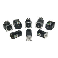
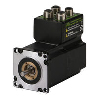
Integrated Step Motors, QuickStep, Including Step Motor Controller SMC75, SMC85
Brand:
JVL
| Category:
Engine
| Size: 7.71 MB
Table of Contents
Table of Contents
3
1 Introduction
7
Examples of Motors and Stand Alone Electronics
7
Stand-Alone Electronics Without Motor
7
Non-Programmable Motors
8
MIS231 Stepmotor
8
Driver Connections
9
Programmable Motors
10
MIS232 with Controller
10
Mis23X, Mis34X, Mis43X Integrated Stepper Motor
11
General Description
12
Basic Modes/Functions in the Quickstep Motor
12
2 Hardware - Intelligent Products
13
Power Supply
14
General Aspects of Power Supply - Only Mis23X Motors
14
Main Power Supply (P+) - Only Mis23X Motors
14
Control Voltage (CVI) - Only Mis23X Motors
15
Power Supply Grounding
15
Dimensioning Power Supply and Fuse - Only Mis23X Motors
15
General Power Supply Description
15
Select Your Power Supply - Only Mis23X Motors
16
Control Voltage (CVI) - Only Mis34X Motors
17
Dimensioning Power Supply and Fuse - Only Mis34X Motors
17
Inputs
18
Input/Output Functional Diagram
18
General Input Features
18
Connection of NPN Output
19
Digital Inputs
20
Analogue Inputs
21
Analogue Inputs Filters
22
Confidence Check
22
Slope Limitation
22
Filtering
22
Confidence Alarms
23
Slope Alarms
23
Example of Analogue Input Filter Operation
23
User Outputs
25
Allowable Output Current as a Function of Duty Cycle
25
Overload of User Outputs
26
Serial Interfaces Overview
27
RS485 Interface
28
RS485 - General Description When Using a Quickstep Motor
28
Special Outputs
30
Error Output
30
In Position Output
30
In Physical Position Output”
30
Pulse/Direction Outputs
31
Encoder Outputs (Only from Version 2.0)
31
Special Connections
32
Quickstep Motor MIS231A1C1N075
32
Handling Noise in Cables
33
About Noise Problems
33
Use Short Cables
33
Use Separate Cables
33
Use Simple Shielding
34
How to Connect Mis23X
35
Connector Overview for the Mis23X
35
Versions with Positioning and Speed Control
35
M12 Connectors
36
How to Connect Mis34X
37
Connector Overview for the Mis34X
37
Mis34Xxxxq5Xxxx Connector Description
38
Drawing and Description of PA0190
50
Usage Hints
50
Diagram of the Internal Details in the PA0190 Junction Box
52
LED Indicators at the Mis34X
53
Indicator Led’s - Description for Products with Canopen
54
LED Indicators at the Mis34X
54
Indicator Led’s - Description for Products with Ethernet
55
3 Hardware Non-Intelligent Products
57
4 Using Mactalk
59
Using the Mactalk Software
60
Mactalk Introduction
60
Toolbar Description
61
Save in Flash
61
Reset Position
61
STOP Motor
61
Saving or Opening a Setup File To/From Disc
62
Register Screen
65
Advanced Screen
66
Test Screen
66
Scope Function
67
How to Update Mactalk
68
How to Update the Motor Firmware
69
How to Update the Encoder Firmware
70
5 Description of Functions
71
Adjusting the Motor Current
72
Current Overview
72
Auto Correction
73
Registers Affected
73
Absolute Position Back-Up
75
Registers Involved
75
Reading the Flash Backup Data
76
Saved Positions, Run Seconds and Counters
76
The Flash Backup Feature Support in Mactalk
77
General Information on How to Connect the SSI Device
78
Setup and Operation of the SSI Function When Using Mactalk
78
Mis23X / SMC75
78
Mis34X / Mis43X / SMC85
78
SSI Encoder/Sensor Interface
78
Field: “Number of Data Bits”
79
Field: “Clock Frequency”
79
Field: “Prepare Time” (Clk to Data)
79
Field: “Disable Intr. When Reading SSI”
79
Additional Hardware Settings
81
Absolute Multi-Turn Encoder
85
Auto-Correction
87
Reading the Encoder Position
88
Presetting a New Encoder Position
88
Position Retention Time
89
Hints to Optimise the Battery Lifetime
89
Battery Life Time as Function of Temperature
89
Firmware Upgrade
90
Updating the Encoder Firmware
90
After Motor Restart
90
Position Limitation Features
91
End-Of Travel Limit Inputs
91
Positive Limit (PL)
91
Negative Limit (NL)
91
Relation between Limit Switch Inputs and the Motor Behaviour
92
Software Position Limits
93
How to Setup the Position Limits
93
Positive Position Limit (PLS)
93
Negative Position Limit (NLS)
93
Relation between Software Limits and the Motor Behaviour
94
Limit Error Handling
95
Limit Handling Optional Only for Mis34X/43X
95
Mechanical Zero Search
96
Zero Search Input
96
6 Modes
97
Passive Mode
98
Velocity Mode
99
Positioning Mode
100
Gear Mode
101
Only Mis23X/Smc75
101
Signal Formats Supported
102
Pulse and Direction Control
102
Quadrature Control
102
How to Connect the Pulse Source
103
Single Ended Signals (Only Mis34X and Mis43X)
103
General Considerations Concerning Cabling
104
Signal Function and Timing
105
Pulse and Direction Format - Timing and How to Connect
106
Quadrature Format - Timing and How to Connect
106
Principle of Gear Mode
107
Velocity
107
Acceleration
107
Encoder (Quadrature) Input
109
Pulse and Direction Input
109
Pulse and Direction Gear Ratio Setup - “Commonly Used Ratios”
109
Mechanical Zero Search Modes
110
Starting a Zero Search
110
The Zero Search Is Disabled
110
Set up the I/O for Zero Search
111
Advanced Settings
111
Sensor Type 1 Zero Search
112
“Sensor Type 2” Zero Search
112
Making a Zero Point Offset
113
Zero Search with Index Pulse (Only Misxxxh2Xx)
114
7 Error Handling
115
Follow Error
115
Position Limit Min. and Max.
115
Error Acceleration
115
8 Registers
117
Introduction to Registers
118
Mis23X Registers
119
Mis23X and SMC75 Register Overview
119
Detailed Description of the Individual Bits
123
Prog-Vers
123
Mode_Reg
124
P_Soll
125
Safe Mode
125
Zero Search Type
125
A_Soll
126
Run_Current
126
Standby_Time
126
V_Soll
126
P_Ist
127
Standby_Current
127
V_Ist
127
Encoder_Pos
128
Gear1
128
Gear2
128
V_Start
128
Flwerr
129
Flwerrrmax
129
Outputs
129
Command
130
Min_P_Ist
130
Status Bits
130
Temp
130
Acc_Emerg
131
Err-Bits
131
Max_P_Ist
131
P_Home
132
Start Mode
132
V_Home
132
Warn_Bits
132
16Bit R/W 1-65535
133
Absolute Encoder Position
133
Access Range 16Bit R/W
133
Home Mode
133
Size
133
Size Access Range
133
Size Access Range 16Bit R/W -1023-1023
133
SSI Encoder Value
133
16Bit R/W 1-65535
134
9.54 Rpm/S
134
Pn
134
Rpm
134
Tn
134
Vn
134
Analogue Filtered
135
Analogue in
135
Busvol
135
Min_Busvol
135
Afzup_Confmin
136
Afzup_Readindex
136
Afzup_Writebits
136
Encoder_Typ
136
Afzup_Confmax
137
Afzup_Filter
137
Afzup_Maxslope
137
Filterstatus
137
Pulsedirmask
138
Pulsedirmod
138
Ssi_Setup
138
Rec_Cnt
139
Sample 1-4
139
Settling Time
139
Ssi_Setup2
139
Buf_Size
140
Index_Offset
140
S_Control
140
S_Time
140
Home_Bits
141
Setup_Bits
141
Iosetup
142
Nl_Mask
143
Turntable_Mode
143
Turntable_Size
143
Can_Setup1
144
Can_Setup2
144
Home_Mask
144
Pl_Mask
144
Error_Mask
145
Inpos_Mask
145
Input Filter Mask
145
Input_Filter_Cnt
145
Acceptance Count
146
Acceptance Voltage
146
Analogue Input Selection
147
P_New
147
Save Threshold Voltage
147
Baud_Rate
148
Group_Id
148
Group_Seq
148
Tx_Delay
148
Motor Type
149
My_Addr
149
Checksum
150
Hardware_Rev
150
Serial_Number
150
Available_Io
151
Bootloader_Ver
151
Max_Voltage
151
Not Saved
151
Ext_Encoder
152
Fbus_Baud
152
Fbus_Node_Id
152
Option_Bits
152
Ext_Encoder_Vel
153
511 5.87Ma
154
Acceleration
154
Default Unit
154
Mactalk Name
154
Max Velocity
154
Mis34X & Mis43X Registers
154
Mis34X, Mis43X and SMC85 Register Overview
154
Running Current
154
Standby Time
154
Prog_Vers
158
9 Building Sequential Programs
189
Getting Started with Programming
190
Programming Main Window
191
Programming Menu
192
How to Build a Program
193
General Programming Hints
196
Command Toolbox Description
197
Graphic Programming Command Reference
198
Enter Your Own Remarks
198
Set Operation Mode
198
Move Operations
198
Unconditional Jump
205
Conditional Jump (Single Input)
205
Wait for Ms before Continuing
207
Set a Register in the MIS Motor
209
Jump According to a Register in the MAC Motor
209
Save Position
210
Zero Search
211
Send Fastmax Command
212
Send Fastmac Command
213
Binary Command
213
Calculator
214
Jump According to a Composition
216
10 Canopen Introduction
217
General Information about Canopen
218
Mis23X (SMC75)
218
Mis34X (SMC85)
218
Cia Membership
218
Canopen, General Information
219
Message-Oriented Protocol
219
Prioritisation of Messages
219
Multi-Master Capability
220
No-Loss Bus Arbitration
220
Short Block Length
220
Header
220
Connecting the Mis23X (SMC75) to the CAN Bus
222
Necessary Accessories for Mis23X (SMC75)
222
Connection and Setup of the CAN Bus
222
EDS (Electronic Data Sheet)
223
Setting the Node ID and Baud Rate
223
Bus Termination
224
CAN Bus Connectors
224
5-Pin Style Connector
224
9-Pin D-Sub Connector
224
The Connector Layout
225
“BUS1” - Canopen Interface. M12 - 5-Pin Male Connector
225
“BUS2” - Canopen Interface. M12 - 5-Pin Female Connector
225
“IO” - I/Os and R485 Interface. M12 - 8-Pin Female Connector.
225
The Canopenexplorer Program
226
An Overall Method for Communication Test
226
Using Canopenexplorer
226
Using Canopenexplorer
227
How to Use Canopenexplorer
229
Objects in the DS301 Standard
231
DS301 Specified Communications Objects
231
Emergency Object
232
Note Regarding “Device Type” (Index 1000)
232
Transmit PDO25
232
Object 2012H – Motor Parameters
233
Enable and Disable Pdos
233
Object 2014H – Motor Parameters (16 Bit)
233
Dynamic Mapping
234
Receive Pdos
235
Receive PDO 22
236
Receive PDO 23
236
Receive PDO 24
236
Transmit Pdos
237
Transmit PDO 21
237
Transmit PDO 22
237
Transmit PDO 23
237
Beckhoff Support
238
PDO Setup in Beckhoff Mode
238
Transmit PDO 25
238
Beckoff Receive PDO Setup
239
Receive PDO1
239
Receive PDO 2
239
Receive PDO 3
239
Beckoff Transmit PDO Setup
240
DSP-402 Support
241
Preconditions
241
Objects Used in the DSP-402 Standard
241
Supported Objects
242
Factors
244
Position Factor
244
Velocity Encoder Factor
245
Acceleration Factor
245
Changing Operation Mode
246
Profile Position Mode
246
Zero Search Mode
246
Supported Pdos
247
Flexible Register Setup
248
Canopen DS-301 Device Profiles
249
More Details of Canopen Theory
249
Boot up Telegram
250
Pdo
251
Write PDO Service
251
Read PDO Service
252
PDO Identifier
252
SDO (Service Data Objects)
252
More Details of Canopen Theory
253
Upload SDO Protocol
253
Abort SDO Transfer Protocol
254
SYNC (Synchronisation Object)
255
Nmt
256
A General NMT Protocol
256
Start Remote Node
256
Stop Remote Node
256
Reset Node
257
Reset Communication
257
Error Control Services
257
Node Guarding/Life Guarding
257
Heartbeat
258
11 Modbus Interface
261
Modbus in Mis34X and SMC85
262
Read Holding Operation
263
Write Multiple Register Operation
263
12 Stand Alone Electronics
265
Step Motor Drivers (Smdxx)
266
Step Motor Controllers (Smcxx)
268
SMC75 Connector Overview
271
Connector J1 - Pin Description
272
How to Connect the Motor
273
Cabling
273
Connection of Step Motor
274
2-Phase Motors (4 Wires).
274
4-Phase Motors (8 Wires).
274
Parallel Connection of Phases
274
Serial Connection
275
Parallel Connection
275
Mis23X: M12 Connections
276
Example of SMC75 Controller Connections
276
5- Pole Connector
276
8-Pole Connector
276
How to Connect in General
276
Quick Start (Smc75A1Mxaa)
277
Getting Started with the Smc75A1Mxaa and Mactalk
277
13 Technical Data
278
Mis23X Technical Data
279
Mis34X Technical Data
280
SMC75 Technical Data
281
Torque Curves
282
Mis23X and Mis34X Torque Curves
282
MIS430 Motor Torque Versus Speed and Supply Voltage
283
MIS432 Motor Torque Versus Speed and Supply Voltage
283
Physical Dimensions
284
Physical Dimensions MIS231, MIS232 and MIS234
284
Life Time
287
Life Time of Ball Bearings in Mis34X
287
Expected Ball Bearing Life Time V.S. Distance
287
Trouble-Shooting Guide
288
14 Connection to Other Equipment
289
Connecting Misxx/Smc75 to SMD73
291
Connecting Misxx/Smc75 to SMD41
292
Connecting Misxx/Smc75 to MAC00-Bx
293
Connection to PLC/PC Boards
294
15 Accessories
295
Cables
296
Power Supplies
297
Psu00-Pd1
297
Psu48-240
297
Other Power Supplies
297
Brakes and Shaft Reinforcement
298
Gear and Brake Mounting Instruction
299
Mounting a Gear or a Brake at the Motor
299
Gears (Product Type to be Mounted)
300
Brakes (Product Type to be Mounted)
300
16 Appendix
301
Mis23X & SMC75 Registers Detailed
302
MIS34/43/SMC85 Registers Detailed
312
MIS34/43/SMC85 Registers Detailed
317
Velocity Accuracy
322
Velocity Acuracy - Only Mis23X
322
Velocity Accuracy - Only Mis34X/43X
322
Command Timing
323
More about Program Timing
324
Motor Connections
325
Serial Communication
327
Supported Commands
327
Read Register
327
Block Description
327
Write Register
328
Enter Safe Mode
328
Exit Safe Mode
328
Write to Flash
329
Reset Controller
329
Group Write Register
330
Program Status and Command
330
MIS Ordering Information
332
SMC75/85 Ordering Information
333
MST Motor Ordering Information
334
17 Declarations
336
CE Declaration of Conformity
337
Vibrationtest Certificate Mis23X
339
Vibrationtest Certificates Mis34X
340
Index
342
Index
343
Advertisement
JVL MIS234 User Manual (367 pages)
Integrated Step Motors, Including Step Motor Controller SMC66, SMC85
Brand:
JVL
| Category:
Engine
| Size: 24.82 MB
Table of Contents
Table of Contents
3
1 Introduction
5
Feature Overview
6
General Description
9
2 Hardware
11
Power Supply
12
User Inputs
21
Analogue Inputs
25
User Outputs
31
Serial Interfaces Overview
33
RS485 Interface
34
EMC Considerations
35
How to Connect a MIS Motor
37
LED Indicators Basic Motor
53
LED Indicators Using Canopen
54
LED Indicators Using Ethernet
55
3 Functional Safety
57
STO - Safe Torque off
58
Safety
60
Installation
63
Commissioning
65
Specifications and Certifications
75
4 Using Mactalk
77
Using the Mactalk Software
78
How to Update Mactalk
86
How to Update the Motor Firmware
87
How to Update the Encoder FW
88
How to Get SW/HW Motor Info
89
5 Description of Functions
91
Setting up the Motor Current
92
Auto Correction
94
Closed Loop Operation
98
Absolute Position Back-Up
108
Multifunction I/O Setup
112
Dedicated Outputs
115
SSI Encoder/Sensor Interface
117
Absolute Multi-Turn Encoder
122
Position Limits
128
Under Voltage Handling
133
Electro Mechanical Brake
136
Turn Table Mode
139
6 Modes
145
Passive Mode
146
Velocity Mode
147
Positioning Mode
148
Gear Mode
149
Zero Search Modes
157
7 Error Handling
165
Setup Error Limits
166
Error Messages
167
8 Registers
177
Introduction to Registers
178
Internal Registers
179
9 Building Sequential Programs
235
Getting Started with Programming
236
Programming Main Window
237
Programming Menu
238
How to Build a Program
239
General Programming Hints
242
Command Toolbox Description
243
Graphic Programming Command Reference
244
Command Timing
263
More about Program Timing
264
10 Ethernet Protocols (Optional)
265
11 Canopen (Optional)
267
General Information about Canopen
268
11.2 Connection and Setup of the CAN Bus
272
Using Canopenexplorer
275
Objects in the DS301 Standard
280
11.5 Objects Used in the DSP-402 Standard
290
Flexible Register Setup
297
More Details of Canopen Theory
298
12 Modbus Interface
309
Modbus
310
13 Stand Alone Electronics
313
Step Motor Controllers (Smcxx)
314
14 Non-Intelligent Products
317
15 Technical Data
319
Mis17X Technical Data
320
Mis23X Technical Data
321
Mis34X Technical Data
322
Mis43X Technical Data
323
Torque Curves
324
Physical Dimensions
333
Life Time
337
Trouble-Shooting Guide
338
16 Accessories
339
Cables
340
Power Supplies
341
Brakes and Shaft Reinforcement
342
Gear and Brake Mounting Instruction
343
17 Appendix
345
Motor Connections
346
Serial Communication
348
Ordering Information
353
Encoder Calibration
354
18 Declarations
355
CE Declaration of Conformity
356
Vibrationtest Certificates
358
UL Certificate - Mis34X
360
TÜV Certificate
362
Advertisement
Related Products
JVL MIS23 Series
JVL MIS232
JVL MIS231
JVL MIS17 Series
JVL MIS171
JVL MIS34 Series
JVL MIS172
JVL MIS176
JVL MIS341
JVL MIS342
JVL Categories
Engine
Game Console
Gateway
Arcade Game Machines
Industrial Equipment
More JVL Manuals
Login
Sign In
OR
Sign in with Facebook
Sign in with Google
Upload manual
Upload from disk
Upload from URL