Mitsubishi Electric FR-F820-00046 Instruction Manual
Fr-f800 series
Hide thumbs
Also See for FR-F820-00046:
- Instruction manual (91 pages) ,
- Installation manuallines (64 pages) ,
- Installation manuallines (64 pages)

Related Manuals for Mitsubishi Electric FR-F820-00046


Summary of Contents for Mitsubishi Electric FR-F820-00046
- Page 1 INVERTER FR-F800 INSTRUCTION MANUAL (DETAILED) Inverter for fans and pumps FR-F820-00046(0.75K) to 04750(110K) FR-F840-00023(0.75K) to 06830(315K) FR-F842-07700(355K) to 12120(560K) FR-F846-00023(0.75K) to 03610(160K)
-
Page 2: Table Of Contents
Safety instructions..............8 Chapter 1 INTRODUCTION . - Page 3 2.8.2 Connection of the brake unit (FR-BU)..............78 2.8.3 Connection of the brake unit (BU type) .
- Page 4 Basic operation procedure (External operation) ........122 4.6.1 Setting the frequency on the operation panel .
- Page 5 (D) Operation command and frequency command ....... . 228 5.6.1 Operation mode selection .
- Page 6 5.11.3 Start count monitor ................395 5.11.4 Traverse function .
- Page 7 Reset method for the protective functions ........563 Check and clear of the fault history .
- Page 8 8.2.3 Premium high-efficiency IPM motor [MM-THE4]............618 Common specifications .
-
Page 9: Safety Instructions
• A person who possesses a certification in regard with electric appliance handling, or person took a proper engineering training. Such training may be available at your local Mitsubishi Electric office. Contact your local sales office for schedules and locations. -
Page 10: Fire Prevention
Electric shock prevention WARNING Do not remove the front cover or the wiring cover while the power of this product is ON, and do not run this product with the front cover or the wiring cover removed as the exposed high voltage terminals or the charging part of the circuitry can be touched. - Page 11 The following instructions must be also followed. If this product is handled incorrectly, it may cause unexpected fault, an injury, or an electric shock. CAUTION Transportation and installation Any person who is opening a package using a sharp object, such as a knife or cutter, must wear gloves to prevent injuries caused by the edge of the sharp object.
- Page 12 WARNING Usage Any person must stay away from the equipment after using the retry function in this product as the equipment will restart suddenly after the output shutoff of this product. Depending on the function settings of this product, the product does not stop its output even when the STOP/RESET key on the operation panel is pressed.
- Page 13 CAUTION Usage The electronic thermal O/L relay function may not be enough for protection of a motor from overheating. It is recommended to install an external thermal relay or a PTC thermistor for overheat protection. Do not use a magnetic contactor on the input side of this product for frequent starting/stopping of this product. Otherwise the life of the product decreases.
- Page 14 General instruction For clarity purpose, illustrations in this Instruction Manual may be drawn with covers or safety guards removed. Ensure all covers and safety guards are properly installed prior to starting operation. For details on the PM motor, refer to the Instruction Manual of the PM motor.
- Page 15 MEMO...
- Page 16 CHAPTER 1 INTRODUCTION Product checking and accessories .........................17 Component names ..............................19 Operation steps ..............................21 About the related manuals............................22...
-
Page 17: Chapter 1 Introduction
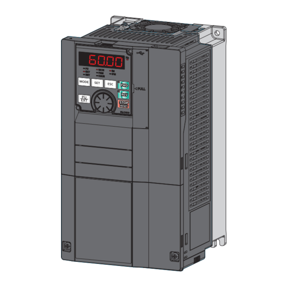
Operation panel (FR-DU08) and LCD operation panel (FR-LU08) Parameter unit Parameter unit (FR-PU07) Operation panel and parameter unit Inverter Mitsubishi Electric inverter FR-F800 series Parameter number (Number assigned to function) PU operation Operation using the PU (operation panel/parameter unit) External operation... -
Page 18: Product Checking And Accessories
Applicable for the FR-F820-00340(7.5K) or higher, and the FR-F840-00170(7.5K) or higher. NOTE • In this Instruction Manual, the inverter model name consists of the inverter rated current and the applicable motor capacity. Example) FR-F820-00046(0.75K) 1. INTRODUCTION 1.1 Product checking and accessories... -
Page 19: Serial Number
Accessory • Fan cover fixing screws These screws are necessary for compliance with the EU Directives. (Refer to the Instruction Manual (Startup).) Capacity Screw size (mm) Quantity FR-F820-00105(2.2K) to FR-F820-00250(5.5K) M3 × 35 FR-F840-00083(3.7K), FR-F840-00126(5.5K) FR-F820-00340(7.5K), FR-F820-00490(11K) M3 × 35 FR-F840-00170(7.5K), FR-F840-00250(11K) FR-F820-00630(15K) to FR-F820-00930(22K) M4 ×... -
Page 20: Component Names
Component names Component names are as follows. 1. INTRODUCTION 1.2 Component names... - Page 21 Refer to Symbol Name Description page Connector for the operation panel or the parameter unit. Also used for RS-485 PU connector communication. USB A connector Connector for a USB memory device. Connector for a personal computer. Enables communication with FR USB mini B connector Configurator2.
-
Page 22: Operation Steps
Operation steps : Initial setting Step of operation Frequency command Installation/mounting Inverter output Wiring of the power frequency supply and motor Time (Hz) Start command Control mode selection Start command via the PU connector to give a start to give a start to give a start and RS-485 terminal of the inverter command? -
Page 23: About The Related Manuals
About the related manuals The manuals related to FR-F800 are as follows. Manual name Manual number FR-F800 Instruction Manual (Startup) IB-0600545 FR-F802 (Separated Converter Type) Instruction Manual (Hardware) IB-0600550ENG FR-CC2 (Converter unit) Instruction Manual IB-0600543ENG FR-F806 (IP55/UL Type 12 specification) Instruction Manual (Hardware) IB-0600676ENG FR Configurator2 Instruction Manual IB-0600516ENG... - Page 24 CHAPTER 2 INSTALLATION AND WIRING Peripheral devices ..............................24 Removal and reinstallation of the operation panel or the front covers..............30 Installation of the inverter and enclosure design ....................34 Terminal connection diagrams..........................43 Main circuit terminals ..............................47 Control circuit................................58 Communication connectors and terminals......................73 Connection of stand-alone option units ........................76...
-
Page 25: Peripheral Devices
INSTALLATION AND WIRING This chapter explains the installation and the wiring of this product. Always read the instructions before use. For the separated converter type, refer to the "INSTALLATION AND WIRING" in the FR-F802 (Separated Converter Type) Instruction Manual (Hardware). For the IP55 compatible model, refer to the "INSTALLATION AND WIRING"... - Page 26 Refer to Symbol Name Overview page The life of the inverter is influenced by the surrounding air temperature. The surrounding air temperature should be as low as possible within the permissible range. This must be noted especially when the inverter is installed in an enclosure.
-
Page 27: Peripheral Devices
Inverter model Power factor improving AC/DC reactor Power factor improving AC/DC reactor (kW) Not installed Installed Not installed Installed 0.75 FR-F820-00046(0.75K) 10 A 10 A S-T10 S-T10 FR-F820-00077(1.5K) 15 A 15 A S-T10 S-T10 FR-F820-00105(2.2K) - Page 28 • When the inverter capacity is larger than the motor capacity, select the MCCB and the MC according to the inverter model, and select cables and the reactor according to the motor output. • When the breaker installed on the inverter input side is shut off, check for the wiring fault (short circuit), damage to internal parts of the inverter etc.
- Page 29 Inverter model Power factor improving AC/DC reactor Power factor improving AC/DC reactor (kW) Not installed Installed Not installed Installed 0.75 FR-F820-00046(0.75K) 10 A 10 A S-T10 S-T10 FR-F820-00077(1.5K) 15 A 15 A S-T10 S-T10 FR-F820-00105(2.2K)
- Page 30 • 400 V class Molded case circuit breaker (MCCB) / earth Magnetic contactor (MC) for installation on Motor leakage circuit breaker (ELB) (type NF or NV) the inverter input side output Inverter model Power factor improving AC/DC reactor Power factor improving AC/DC reactor (kW) Not installed Installed...
-
Page 31: Removal And Reinstallation Of The Operation Panel Or The Front Covers
Removal and reinstallation of the operation panel or the front covers Removal and reinstallation of the operation panel • Loosen the two screws on the operation panel. • Press the upper edge of the operation panel while pulling (These screws cannot be removed.) out the operation panel. - Page 32 Removal of the front cover (upper side) (FR-F820-01540(37K) or lower, FR-F840-00770(37K) or lower) Loosen Loosen Loosen (a) With the front cover (lower side) removed, loosen the mounting screws on the front cover (upper side). (These screws cannot be removed.) (FR-F820-00340(7.5K) to FR-F820-01540(37K) and FR-F840-00170(7.5K) to FR-F840-00770(37K) have two mounting screws.) (b) While holding the areas around the installation hooks on the sides of the front cover (upper side), pull out the cover using...
- Page 33 Removal of the front cover (lower side) (FR-F820-01870(45K) or higher, FR-F840-00930(45K) or higher) (a) When the mounting screws are removed, the front cover (lower side) can be removed. (b) With the front cover (lower side) removed, wiring of the main circuit terminals can be performed. ...
- Page 34 Reinstallation of the front covers (FR-F820-01870(45K) or higher, FR- F840-00930(45K) or higher) Fasten Fasten Fasten Fasten Fasten Fasten (a) Insert the upper hooks of the front cover (upper side) into the sockets of the inverter. Securely install the front cover (upper side) to the inverter by fixing the hooks on the sides of the cover into place. (b) Tighten the mounting screw(s) at the lower part of the front cover (upper side).
-
Page 35: Installation Of The Inverter And Enclosure Design
Installation of the inverter and enclosure design When designing or manufacturing an inverter enclosure, determine the structure, size, and device layout of the enclosure by fully considering the conditions such as heat generation of the contained devices and the operating environment. An inverter unit uses many semiconductor devices. - Page 36 NOTE • For the amount of heat generated by the inverter unit, refer to page Humidity Operate the inverter within the ambient air humidity of usually 45 to 90% (up to 95% with circuit board coating). Too high humidity will pose problems of reduced insulation and metal corrosion. On the other hand, too low humidity may cause a spatial electrical breakdown.
- Page 37 Vibration, impact The vibration resistance of the inverter is up to 5.9 m/s (2.9 m/s or less for the FR-F840-04320(185K) or higher) at 10 to 55 Hz frequency and 1 mm amplitude for the directions of X, Y, Z axes. Applying vibration and impacts for a long time may loosen the structures and cause poor contacts of connectors, even if those vibration and impacts are within the specified values.
-
Page 38: Amount Of Heat Generated By The Inverter
Installing the heatsink inside the enclosure When the heatsink is installed inside the enclosure, the amount of heat generated by the inverter unit is shown in the following tables. Amount of heat generated (W) Voltage Inverter model FR-F820-00046(0.75K) FR-F820-00077(1.5K) FR-F820-00105(2.2K) FR-F820-00167(3.7K) FR-F820-00250(5.5K) FR-F820-00340(7.5K) -
Page 39: Cooling System Types For Inverter Enclosure
Installing the heatsink outside the enclosure When the heatsink is installed outside the enclosure, the amount of heat generated by the inverter unit is shown in the following tables. (For the details on protruding the heatsink through a panel, refer to page 41.) Amount of heat generated (W) -
Page 40: Inverter Installation
• Cooling by ventilation (forced ventilation type, pipe ventilation type) • Cooling by heat exchanger or cooler (heat pipe, cooler, etc.) Cooling system Enclosure structure Comment This system is low in cost and generally used, but the Natural ventilation (enclosed enclosure size increases as the inverter capacity type / open type) increases. - Page 41 • When designing or building an enclosure for the inverter, carefully consider influencing factors such as heat generation of the contained devices and the operating environment. Clearances (front) Clearances (side) FR-F820-03160(75K) or lower, FR-F820-03800(90K) or higher, FR-F840-01800(75K) or lower FR-F840-02160(90K) or higher 20 cm 10 cm or more...
-
Page 42: Protruding The Heat Sink Through A Panel
Arrangement of the ventilation fan and inverter Heat generated in the inverter is blown up from the bottom of the unit as warm air by the cooling fan. When installing a ventilation fan for that heat, determine the place of ventilation fan installation after fully considering an air flow. (Air passes through areas of low resistance. - Page 43 When reattaching the installation frames, make sure that the installation orientation is correct. Shift Upper installation frame Lower installation Shift frame Installation of the inverter on the enclosure Push the inverter heat sink part outside the enclosure, and fix the inverter to the panel with upper and lower installation frames. Enclosure Inside the Exhausted air...
-
Page 44: Terminal Connection Diagrams
Terminal connection diagrams Type FM FR-F820-00770(18.5K) to 01250(30K), FR-F840-00470(22K) to 01800(75K) DC reactor (FR-HEL)∗1 DC reactor Brake unit (Option) (FR-HEL)∗1 Sink logic Brake unit (Option) Jumper Main circuit terminal Earth ∗8 (Ground) Control circuit terminal Jumper∗7 Jumper Earth PR ∗7 N/- (Ground) Inrush PX∗7 PR∗7 N/-... - Page 45 For the FR-F820-03160(75K) or higher and the FR-F840-01800(75K) or higher, always connect the DC reactor option FR-HEL. Refer to page to select the right DC reactor according to the applicable motor capacity. To connect a DC reactor, remove the jumper installed across terminals P1 and P/+ before installing the DC reactor. (A jumper is not installed in the FR-A820-03160(75K) or higher and the FR-A840-01800(75K) or higher.) When using separate power supply for the control circuit, remove the jumper between R1/L11 and S1/L21.
-
Page 46: Main Circuit
Type CA FR-F820-00770(18.5K) to 01250(30K), FR-F840-00470(22K) to 01800(75K) DC reactor (FR-HEL)∗1 DC reactor Brake unit (Option) (FR-HEL)∗1 Sourse logic Brake unit Jumper (Option) Main circuit terminal Earth ∗8 (Ground) Control circuit terminal Jumper Jumper∗7 Earth PR ∗7 N/- (Ground) Inrush PX∗7 PR∗7 N/- current... - Page 47 When using separate power supply for the control circuit, remove the jumper between R1/L11 and S1/L21. The function of these terminals can be changed using the Input terminal function selection (Pr.178 to Pr.189). (Refer to page 355.) Terminal JOG is also used as a pulse train input terminal. Use Pr.291 to choose JOG or pulse. Terminal input specifications can be changed by analog input specification switchover (Pr.73, Pr.267).
-
Page 48: Main Circuit Terminals
Main circuit terminals 2.5.1 Details on the main circuit terminals Terminal Refer to Terminal name Terminal function description symbol page Connect these terminals to the commercial power supply. R/L1, S/L2, T/ AC power input Do not connect anything to these terminals when using the high power factor —... -
Page 49: Main Circuit Terminal Layout And Wiring To Power Supply And Motor
2.5.2 Main circuit terminal layout and wiring to power supply and motor FR-F820-00046(0.75K), FR-F820-00077(1.5K) FR-F820-00105(2.2K) to FR-F820-00250(5.5K) FR-F840-00023(0.75K) to FR-F840-00126(5.5K) Jumper Jumper R/L1 S/L2 T/L3 Jumper R/L1 S/L2 T/L3 P/+ PR Jumper R1/L11 S1/L21 R1/L11 S1/L21 Charge lamp Power supply... - Page 50 FR-F820-01870(45K), FR-F820-02330(55K) FR-F820-03160(75K) R1/L11 S1/L21 R1/L11 S1/L21 Charge lamp Charge lamp Jumper Jumper R/L1 S/L2 T/L3 R/L1 S/L2 T/L3 N/- Jumper Power supply Motor Power supply DC reactor Motor (option) FR-F820-03800(90K), FR-F820-04750(110K) FR-F840-00930(45K) to FR-F840-01800(75K) FR-F840-03250(132K) to FR-F840-04810(220K) R1/L11 S1/L21 R1/L11 S1/L21 Charge lamp Charge lamp...
-
Page 51: Applicable Cables And Wiring Length
NOTE • Make sure the power cables are connected to the R/L1, S/L2, and T/L3. (Phase need not be matched.) Never connect the power cable to the U, V, and W of the inverter. Doing so will damage the inverter. •... - Page 52 For LD rating (Pr.570 Multiple rating setting = "1") • 200 V class (220 V input power supply, without a power factor improving AC or DC reactor) Cable gauge Crimp terminal HIV cables, etc. (mm AWG/MCM PVC cables, etc. (mm Applicable Terminal Tightening...
- Page 53 • 400 V class (440 V input power supply, with a power factor improving AC or DC reactor) Cable gauge Crimp terminal Applicable Terminal Tightening HIV cables, etc. (mm AWG/MCM PVC cables, etc. (mm inverter model screw torque R/L1, S/ R/L1, Earthing R/L1,...
- Page 54 For SLD rating (Pr.570 Multiple rating setting = "0") • 200 V class (220 V input power supply, without a power factor improving AC or DC reactor) Cable gauge Crimp terminal HIV cables, etc. (mm AWG/MCM PVC cables, etc. (mm Applicable Terminal Tightening...
- Page 55 • 400 V class (440 V input power supply, with a power factor improving AC or DC reactor) Cable gauge Crimp terminal Applicable Terminal Tightening HIV cables, etc. (mm AWG/MCM PVC cables, etc. (mm inverter model screw torque R/L1, S/ R/L1, Earthing R/L1,...
- Page 56 Total wiring length With induction motor Connect one or more general-purpose motors within the total wiring length shown in the following table. Pr.72 setting FR-F820-00046(0.75K), FR-F820-00077(1.5K), FR-F820-00105(2.2K) or higher, FR- (carrier frequency) FR-F840-00023(0.75K) FR-F840-00038(1.5K) F840-00052(2.2K) or higher 2 (2 kHz) or lower...
- Page 57 With PM motor Use the following length of wiring or shorter when connecting a PM motor. FR-F820-00077(1.5K) or lower, FR-F820-00105(2.2K) or higher, Voltage class Pr.72 setting (carrier frequency) FR-F840-00038(1.5K) or lower FR-F840-00052(2.2K) or higher 200 V 0 (2 kHz) to 15 (14 kHz) 100 m 100 m 5 or lower (2 kHz)
-
Page 58: Earthing (Grounding) Precautions
2.5.4 Earthing (grounding) precautions Always earth (ground) the motor and inverter. Purpose of earthing (grounding) Generally, an electrical apparatus has an earth (ground) terminal, which must be connected to the ground before use. An electrical circuit is usually insulated by an insulating material and encased. However, it is impossible to manufacture an insulating material that can shut off a leakage current completely, and actually, a slight current flows into the case. -
Page 59: Control Circuit
Control circuit 2.6.1 Details on the control circuit terminals Input signal Terminal Refer Type Terminal name Terminal function description Rated specification symbol to page Forward rotation Turn ON the STF signal to start forward When the STF and STR start rotation and turn it OFF to stop. - Page 60 Terminal Refer Type Terminal name Terminal function description Rated specification symbol to page 10 ±0.4 VDC, When connecting the frequency setting potentiometer at an initial permissible load Frequency setting status, connect it to terminal 10. current: 10 mA power supply Change the input specifications of terminal 2 using Pr.73 when 5 ±0.5 VDC, permissible connecting it to terminal 10E.
- Page 61 Output signal Terminal Refer Type Terminal name Terminal function description Rated specification symbol to page 1 changeover contact output that indicates that an inverter's protective function has been activated and the outputs are A1, B1, Relay output 1 (fault stopped.
- Page 62 Communication Terminal Refer Type Terminal name Terminal function description symbol to page RS-485 communication can be made through the PU connector (for connection on a 1:1 basis only). Conforming standard: EIA-485 (RS-485) — PU connector Transmission format: Multidrop link Transmission speed: 4800 to 115200 bps Wiring length: 500 m TXD+...
-
Page 63: Control Logic (Sink/Source) Change
2.6.2 Control logic (sink/source) change Switch the control logic of input signals as necessary. To change the control logic, change the jumper connector position on the control circuit board. Connect the jumper connector to the connector pin of the desired control logic. The control logic of input signals is initially set to the sink logic (SINK) for the type FM inverter. -
Page 64: Wiring Of Control Circuit
• When using an external power supply for transistor output Sink logic Source logic Use terminal PC as a common terminal, and perform wiring as Use terminal SD as a common terminal, and perform wiring as shown below. (Do not connect terminal SD on the inverter with shown below. - Page 65 Crimp the blade terminal. Insert wires to a blade terminal, and check that the wires come out for about 0 to 0.5 mm from a sleeve. Check the condition of the blade terminal after crimping. Do not use a blade terminal of which the crimping is inappropriate, or the face is damaged.
- Page 66 Wire removal Pull the wire while pushing the open/close button all the way down firmly with a flathead screwdriver. Open/close button Flathead screwdriver NOTE • Pulling out the wire forcefully without pushing the open/close button all the way down may damage the terminal block. •...
-
Page 67: Wiring Precautions
2.6.4 Wiring precautions • It is recommended to use a cable of 0.3 to 0.75 mm for the connection to the control circuit terminals. • The wiring length should be 30 m (200 m for terminal FM) at the maximum. •... - Page 68 Connection method Connection diagram If a fault occurs and the electromagnetic contactor (MC) installed at the inverter's input line is opened, power supply to the control circuit is also stopped and the fault Inverter signals cannot be output anymore. Terminals R1/L11 and S1/L21 of the control R/L1 circuit are provided to keep outputting the fault signals in such a case.
- Page 69 • FR-F820-00770(18.5K) or higher, FR-F840-00470(22K) or higher R1/L11 S1/L21 Power supply terminal block for the control circuit Power supply terminal block for the control circuit R/L1 S/L2 T/L3 R1/L11 S1/L21 Main power supply FR-F820-00770(18.5K) to 01250(30K) FR-F840-00470(22K), FR-F820-01540(37K) FR-F820-01870(45K) or higher 00620(30K) FR-F840-00770(37K) FR-F840-00930(45K) or higher...
-
Page 70: When Supplying 24 V External Power To The Control Circuit
2.6.6 When supplying 24 V external power to the control circuit Connect the 24 V external power supply across terminals +24 and SD to turn the I/O terminal ON/OFF operation, keep the operation panel ON, and carry out communication during communication operation even at power-OFF state of inverter's main circuit power supply. -
Page 71: Safety Stop Function
• The alarms, which have occurred when the main circuit power supply is ON, continue to be output after the power supply is changed to the 24 V external power supply. Perform the inverter reset or turn OFF then ON the power to reset the faults. •... - Page 72 Connection diagram To prevent restart at failure occurrence, connect terminals So (SO) and SOC to the reset button, which are the feedback input terminals of the safety relay module. Inverter R/L1 S/L2 T/L3 So (SO) Logic IGBTs +24V Gate Gate Fuse ASIC...
- Page 73 If another warning occurs when the warning SA occurs, the other warning indication may be displayed. The ON/OFF state of the output signal is the one for the positive logic. The ON and OFF are reversed for the negative logic. For the SAFE signal, refer to the following table and use any of Pr.190 to Pr.196 (output terminal function selection) to assign the function to the output terminal.
-
Page 74: Communication Connectors And Terminals
Communication connectors and terminals 2.7.1 PU connector Mounting the operation panel or the parameter unit on the enclosure surface • Having an operation panel or a parameter unit on the enclosure surface is convenient. With a connection cable, the operation panel or the parameter unit can be mounted to the enclosure surface and connected to the inverter. -
Page 75: Usb Connector
2.7.2 USB connector USB host (A connector) USB memory device Communication status Place a flathead screwdriver, indicator (LED) etc. in a slot and push up the USB device cover to open. (Mini B connector) Personal computer (FR Configurator2) USB host communication Interface Conforms to USB 1.1 Transmission speed... -
Page 76: Rs-485 Terminal Block
NOTE • Do not connect devices other than a USB memory device to the inverter. • If a USB device is connected to the inverter via a USB hub, the inverter cannot recognize the USB memory device properly. USB device communication The inverter can be connected to a personal computer with a USB (ver. -
Page 77: Connection Of Stand-Alone Option Units
Connection of stand-alone option units The inverter accepts a variety of stand-alone option units as required. Incorrect connection will cause inverter damage or accident. Connect and operate the option unit carefully in accordance with the Instruction Manual of the corresponding option unit. 2.8.1 Connection of the brake unit (FR-BU2) Connect the brake unit (FR-BU2(-H)) as follows to improve the braking capability during deceleration. - Page 78 Connection example with the FR-BR(-H) resistor unit ∗2 FR-BR MCCB Motor R/L1 ∗4 Three phase AC S/L2 power supply T/L3 ∗3 FR-BU2 Inverter P/+ (P3) ∗5 ∗1 ∗3 10 m or less When wiring, make sure to match the terminal symbols (P/+, N/-) on the inverter and on the brake unit (FR-BU2). (Incorrect connection will damage the inverter and brake unit.) When the power supply is 400 V class, install a stepdown transformer.
-
Page 79: Connection Of The Brake Unit (Fr-Bu)
2.8.2 Connection of the brake unit (FR-BU) Connect the brake unit (FR-BU(-H)) as follows to improve the braking capability during deceleration. The FR-BU is compatible with the FR-F820-02330(55K) or lower and the FR-F840-01160(55K) and lower. ∗2 FR-BR MCCB Motor R/L1 Three-phase AC S/L2 power supply... -
Page 80: Connection Of The High Power Factor Converter (Fr-Hc2)
NOTE • The wiring distance between the inverter, brake unit, and discharging resistor must be within 2 m. Even when the cable is twisted, the wiring length must be within 5 m. • If the transistors in the brake unit should become faulty, the resistor will overheat and result in a fire. Install a magnetic contactor on the inverter's input side and configure a circuit that shut off the current in case of a fault. -
Page 81: Connection Of The Power Regeneration Common Converter (Fr-Cv)
2.8.5 Connection of the power regeneration common converter (FR-CV) When wiring for connecting the power regeneration common converter (FR-CV) to the inverter, make sure to match the terminal symbols (P/+, N/-) on the inverter and on the power regeneration common converter. The FR-CV is compatible with the FR-F820-02330(55K) or lower and the FR-F840-01160(55K) or lower. -
Page 82: Connection Of The Power Regeneration Converter (Mt-Rc)
2.8.6 Connection of the power regeneration converter (MT-RC) When connecting the power regeneration converter (MT-RC), perform wiring securely as follows. Incorrect connection will damage the power regeneration converter and the inverter. The MT-RC is compatible with FR-F840-01800(75K) or higher. After making sure that the wiring is correct and secure, set "1" in Pr.30 Regenerative function selection. Inverter MCCB R/L1... - Page 83 • When using the DC reactor (FR-HEL), connect it to terminals P/+ and P1. In this case, the jumper connected across terminals P/+ and P1 must be removed. Otherwise, the reactor will not be effective. (The jumper is not installed for the FR-F820-03160(75K) or higher and the FR-F840-01800(75K) or higher.) FR-HEL Remove the jumper...
- Page 84 CHAPTER 3 PRECAUTIONS FOR USE OF THE INVERTER Electro-magnetic interference (EMI) and leakage currents ..................84 Power supply harmonics............................91 Installation of a reactor ............................95 Power shutdown and magnetic contactor (MC)......................96 Countermeasures against deterioration of the 400 V class motor insulation............98 Checklist before starting operation .........................99 Failsafe system which uses the inverter .......................102...
-
Page 85: Chapter 3 Precautions For Use Of The Inverter
PRECAUTIONS FOR USE OF THE INVERTER This chapter explains the precautions for use of this product. Always read the instructions before use. For the separated converter type, refer to the "PRECAUTIONS FOR USE OF THE INVERTER" in the FR-F802 (Separated Converter Type) Instruction Manual (Hardware). - Page 86 MCCB Thermal relay Motor Power Inverter supply Line-to-line static capacitances Line-to-line leakage currents path Countermeasures • Use Pr.9 Electronic thermal O/L relay. • If the carrier frequency setting is high, decrease the Pr.72 PWM frequency selection setting. Note that motor noise increases. Selecting Pr.240 Soft-PWM operation selection makes the sound inoffensive. To ensure that the motor is protected against line-to-line leakage currents, it is recommended to use a temperature sensor to directly detect motor temperature.
-
Page 87: Techniques And Measures For Electromagnetic Compatibility (Emc)
Breaker designed Item for harmonic and Standard breaker Example surge suppression 5.5 mm 5.5 mm 50 m Leakage current Ig1 (mA) 33 × = 0.17 1000m Noise Leakage current Ign (mA) 0 (without noise filter) filter 3φ Inverter 200 V 1 (without EMC filter). - Page 88 • Use shielded twisted pair cables for the detector connecting and control signal cables and connect the sheathes of the shielded cables to terminal SD. • Ground (Earth) the inverter, motor, etc. at one point. EMS measures to reduce electromagnetic noises that enter the inverter and cause it to malfunction When devices that generate many electromagnetic noises (which use magnetic contactors, electromagnetic brakes, many relays, for example) are installed near the inverter and the inverter may malfunction due to electromagnetic noises, the...
-
Page 89: Built-In Emc Filter
Noise propagation Countermeasure path When the power supplies of the peripheral devices are connected to the power supply of the inverter in the same line, inverter-generated noises may flow back through the power supply cables to cause malfunction of the devices and the following countermeasures must be taken: •... - Page 90 The input side common mode choke, which is built in the FR-F820-02330(55K) or lower and the FR-F840-01160(55K) or lower inverter, is always enabled regardless of the EMC filter ON/OFF connector setting. FR-F820-00046(0.75K), FR-F820-00105(2.2K) to 00250(5.5K) FR-F820-00340(7.5K) to 00630(15K) FR-F820-00770(18.5K) or higher 00077(1.5K)
- Page 91 WARNING • While power is ON or when the inverter is running, do not open the front cover. Otherwise you may get an electric shock. 3. PRECAUTIONS FOR USE OF THE INVERTER 3.1 Electro-magnetic interference (EMI) and leakage currents...
-
Page 92: Power Supply Harmonics
Power supply harmonics 3.2.1 Power supply harmonics The inverter may generate power supply harmonics from its converter circuit to affect the power generator, power factor correction capacitor etc. Power supply harmonics are different from noise and leakage currents in source, frequency band and transmission path. - Page 93 The three-phase 200 V input specifications 3.7 kW or lower were previously covered by "the Harmonic Suppression Guidelines for Household Appliances and General-purpose Products" and other models were covered by "the Harmonic Suppression Guidelines for Consumers Who Receive High Voltage or Special High Voltage". However, the transistorized inverter has been excluded from the target products covered by "the Harmonic Suppression Guidelines for Household Appliances and General- purpose Products"...
- Page 94 Equivalent capacity limit Received power voltage Reference capacity 6.6 kV 50 kVA 22/33 kV 300 kVA 66 kV or more 2000 kVA Harmonic content (when the fundamental current is considered as 100%) Reactor 11th 13th 17th 19th 23rd 25th Not used Used (AC side)
- Page 95 Fundamental Fundamental Outgoing harmonic current converted from 6.6 kV (mA) (with a DC reactor, Rated Applicable wave current (A) wave current 100% operation ratio) capacity motor (kW) converted from (kVA) 200 V 400 V 11th 13th 17th 19th 23rd 25th 6.6 kV (mA) 7455 87.2...
-
Page 96: Installation Of A Reactor
Installation of a reactor When the inverter is connected near a large-capacity power transformer (1000 kVA or more) or when a power factor correction capacitor is to be switched over, an excessive peak current may flow in the power input circuit, damaging the converter circuit. To prevent this, always install an AC reactor (FR-HAL), which is available as an option. -
Page 97: Power Shutdown And Magnetic Contactor (Mc)
Power shutdown and magnetic contactor (MC) Inverter input side magnetic contactor (MC) On the inverter input side, it is recommended to provide an MC for the following purposes. (Refer to page 26 for selection.) • To disconnect the inverter from the power supply at activation of a protective function or at malfunctioning of the driving system (emergency stop, etc.). - Page 98 NOTE • Before wiring or inspection for a PM motor, confirm that the PM motor is stopped. In an application, such as fan and blower, where the motor is driven by the load, a low-voltage manual contactor must be connected at the inverter's output side, and wiring and inspection must be performed while the contactor is open.
-
Page 99: Countermeasures Against Deterioration Of The 400 V Class Motor Insulation
Countermeasures against deterioration of the 400 V class motor insulation In the PWM type inverter, a surge voltage attributable to wiring constants is generated at the motor terminals. Especially in a 400 V class motor, the surge voltage may deteriorate the insulation. When the 400 V class motor is driven by the inverter, consider the following countermeasures: ... -
Page 100: Checklist Before Starting Operation
Checklist before starting operation The FR-F800 series inverter is a highly reliable product, but incorrect peripheral circuit making or operation/handling method may shorten the product life or damage the product. Before starting operation, always recheck the following points. Refer to Check by Checkpoint Countermeasure... - Page 101 Refer to Check by Checkpoint Countermeasure page user When using a switching circuit as shown below, chattering due to misconfigured sequence or arc generated at switching may allow undesirable current to flow in and damage the inverter. Miswiring may also damage the inverter. (Note that a PM motor cannot be driven by the commercial power supply.) Interlock When using the electronic bypass...
- Page 102 Refer to Check by Checkpoint Countermeasure page user When a motor is driven by the inverter, axial voltage is generated on the motor shaft, which may cause electrical corrosion of the bearing in rare cases depending on the wiring, load, operating conditions of the motor or specific inverter settings (high carrier frequency and EMC filter ON).
-
Page 103: Failsafe System Which Uses The Inverter
Failsafe system which uses the inverter When a fault is detected by the protective function, the protective function activates and outputs the Fault signal. However, the Fault signal may not be output at an inverter's fault occurrence when the detection circuit or output circuit fails, etc. Although Mitsubishi assures the best quality products, provide an interlock which uses inverter status output signals to prevent accidents such as damage to the machine when the inverter fails for some reason. - Page 104 Checking the inverter operating status by using the start signal input to the inverter and the Inverter running signal output from the inverter ... (c) The Inverter running (RUN) signal is output when the inverter is running. (The RUN signal is assigned to terminal RUN in the initial setting.) Check if the RUN signal is output while a start signal (the STF/STR signal for forward/reverse rotation command) is input to the inverter.
- Page 105 Command speed and actual operation check Check for a gap between the actual speed and commanded speed by comparing the inverter's speed command and the speed detected by the speed detector. Controller System failure Sensor Inverter (speed, temperature, air volume, etc.) To the alarm detection sensor 3.
- Page 106 CHAPTER 4 BASIC OPERATION Operation panel (FR-DU08)..........................106 Monitoring the inverter ............................111 Easy setting of the inverter operation mode ......................112 Frequently-used parameters (simple mode parameters)..................114 Basic operation procedure (PU operation) ......................116 Basic operation procedure (External operation) ....................122 Basic operation procedure (JOG operation) ......................129...
-
Page 107: Operation Panel (Fr-Du08)
BASIC OPERATION This chapter explains the basic operation of this product. Always read the instructions before use. Operation panel (FR-DU08) 4.1.1 Components of the operation panel (FR-DU08) To mount the operation panel (FR-DU08) on the enclosure surface, refer to page 4. - Page 108 STOP/RESET key Used to reset the inverter when the protective function is activated. The setting dial of the Mitsubishi Electric inverters. Turn the setting dial to change the setting of frequency or parameter, etc. Press the setting dial to perform the following operations: Setting dial •...
-
Page 109: Basic Operation Of The Operation Panel
4.1.2 Basic operation of the operation panel Basic operation Operation mode switchover/Frequency setting External operation mode ∗1( displayed at power-ON) PU Jog operation mode ∗1 ∗1 PU operation mode Alternating (Example) Change the setting. Frequency setting written and complete Second screen Third screen ∗2... -
Page 110: Digital Characters And Their Corresponding Printed Equivalents
Changes parameter settings as a batch. The target parameters include Automatic parameter communication parameters for the Mitsubishi Electric human machine setting interface (GOT) connection and the parameters for the rated frequency settings of 50 Hz/60 Hz. -
Page 111: Changing The Parameter Setting Value
4.1.4 Changing the parameter setting value The following shows the procedure to change the setting of Pr.1 Maximum frequency. Operating procedure Turning ON the power of the inverter The operation panel is in the monitor mode. Changing the operation mode Press to choose the PU operation mode. -
Page 112: Monitoring The Inverter
Monitoring the inverter 4.2.1 Monitoring of output current and output voltage • Press on the operation panel in the monitor mode to switch the monitor item between output frequency, output current, and output voltage. Operating procedure Press during inverter operation to monitor the output frequency. [Hz] indicator turns ON. Press to monitor the output current. -
Page 113: Easy Setting Of The Inverter Operation Mode
Easy setting of the inverter operation mode The operation mode suitable for start and speed command combinations can be set easily using Pr.79 Operation mode selection. The following shows the procedure to operate with the external start command (STF/STR) and the frequency command by using Operating procedure Press... - Page 114 NOTE • " " appears if the Pr.79 setting is tried to be changed while the inverter is set that only the parameters registered in the user group are read (Pr.160 = "1") but Pr.79 is not included in the user group. •...
-
Page 115: Frequently-Used Parameters (Simple Mode Parameters)
Frequently-used parameters (simple mode parameters) Parameters that are frequently used for the FR-F800 series are grouped as simple mode parameters. When Pr.160 User group read selection = "9999", only the simple mode parameters are displayed on the operation panel. This section explains the simple mode parameters. 4.4.1 Simple mode parameter list For simple variable-speed operation of the inverter, the initial values of the parameters may be used as they are. - Page 116 50/60 Hz. Initial value for the FR-F820-00046(0.75K) or lower and FR-F840-00023(0.75K) or lower. Initial value for the FR-F820-00077(1.5K) to FR-F820-00167(3.7K) and the FR-F840-00038(1.5K) to FR-F840-00083(3.7K). Initial value for the FR-F820-00250(5.5K), FR-F820-00340(7.5K), FR-F840-00126(5.5K), and FR-F840-00170(7.5K).
-
Page 117: Basic Operation Procedure (Pu Operation)
Basic operation procedure (PU operation) Select a method to give the frequency command from the list below, and refer to the specified page for its procedure. Method to give the frequency command Refer to page Setting the frequency on the operation panel in the frequency setting mode Give commands by turning the setting dial like a potentiometer Give commands by turning ON/OFF switches wired to inverter's terminals (multi-speed setting) Setting the frequency by inputting voltage signals... -
Page 118: Perform Pu Operation Using The Setting Dial Like A Potentiometer
Deceleration → stop Press to stop. The frequency value on the monitor decreases according to the setting of Pr.8 Deceleration time, the monitor displays " " (0.00 Hz), and the motor stops rotating. NOTE • To display the set frequency under PU operation mode or External/PU combined operation mode 1 (Pr.79 = "3"), press (Refer to page 288.) -
Page 119: Setting The Frequency With Switches (Multi-Speed Setting)
4.5.3 Setting the frequency with switches (multi-speed setting) • Use on the operation panel (FR-DU08) to give a start command. • Turn ON the RH, RM, or RL signal to give a frequency command (multi-speed setting). • Set Pr.79 Operation mode selection = "4" (External/PU combination operation mode 2). [Connection diagram] Speed 1 Inverter... -
Page 120: Setting The Frequency Using An Analog Signal (Voltage Input)
4.5.4 Setting the frequency using an analog signal (voltage input) • Use on the operation panel (FR-DU08) to give a start command. • Use the frequency setting potentiometer to give a frequency command (by connecting it to terminals 2 and 5 (voltage input)). •... -
Page 121: Setting The Frequency Using An Analog Signal (Current Input)
4.5.5 Setting the frequency using an analog signal (current input) • Use on the operation panel (FR-DU08) to give a start command. • Use the current regulator which outputs 4 to 20 mA to give a frequency command (by connecting it across terminals 4 and 5 (current input)). - Page 122 Pr.184 AU terminal function selectionpage 355 C5(Pr.904) Terminal 4 frequency setting bias frequencypage 339 4. BASIC OPERATION 4.5 Basic operation procedure (PU operation)
-
Page 123: Basic Operation Procedure (External Operation)
Basic operation procedure (External operation) Select a method to give the frequency command from the list below, and refer to the specified page for its procedure. Method to give the frequency command Refer to page Setting the frequency on the operation panel in the frequency setting mode Turning ON/OFF switches wired to inverter's terminals (multi-speed setting) Setting the frequency by inputting voltage signals Setting the frequency by inputting current signals... -
Page 124: Setting The Frequency And Giving A Start Command With Switches (Multi-Speed Setting) (Pr.4 To Pr.6)
NOTE • When both the forward rotation start switch (STF signal) and the reverse rotation start switch (STR signal) are turned ON, the motor cannot be started. If both are turned ON while the inverter is running, the inverter decelerates to a stop. •... -
Page 125: Setting The Frequency Using An Analog Signal (Voltage Input)
NOTE • When both the forward rotation start switch (STF signal) and the reverse rotation start switch (STR signal) are turned ON, the motor cannot be started. If both are turned ON while the inverter is running, the inverter decelerates to a stop. •... - Page 126 NOTE • When both the forward rotation start switch (STF signal) and the reverse rotation start switch (STR signal) are turned ON, the motor cannot be started. If both are turned ON while the inverter is running, the inverter decelerates to a stop. •...
-
Page 127: Changing The Frequency (60 Hz, Initial Value) At The Maximum Voltage Input (5 V, Initial Value)
4.6.4 Changing the frequency (60 Hz, initial value) at the maximum voltage input (5 V, initial value) • Change the maximum frequency. The following shows the procedure to change the frequency at 5 V from 60 Hz (initial value) to 50 Hz using a frequency setting potentiometer for 0 to 5 VDC input. -
Page 128: Setting The Frequency Using An Analog Signal (Current Input)
4.6.5 Setting the frequency using an analog signal (current input) • Turn ON the STF/STR signal to give a start command. • Turn ON the AU signal. • Set Pr.79 Operation mode selection = "2" (External operation mode). [Connection diagram] Inverter Forward rotation start Reverse rotation start... -
Page 129: Changing The Frequency (60 Hz, Initial Value) At The Maximum Current Input (At 20 Ma, Initial Value)
4.6.6 Changing the frequency (60 Hz, initial value) at the maximum current input (at 20 mA, initial value) • Change the maximum frequency. The following shows the procedure to change the frequency at 20 mA from 60 Hz (initial value) to 50 Hz using a frequency setting potentiometer for 4 to 20 mA input. -
Page 130: Basic Operation Procedure (Jog Operation)
Basic operation procedure (JOG operation) 4.7.1 Giving a start command by using external signals for JOG operation • JOG operation is performed while the JOG signal is ON. • Use Pr.15 Jog frequency to set a frequency, and set Pr.16 Jog acceleration/deceleration time to set the acceleration/ deceleration time for JOG operation. -
Page 131: Giving A Start Command From The Operation Panel For Jog Operation
4.7.2 Giving a start command from the operation panel for JOG operation • JOG operation is performed while on the operation panel is pressed. Operation panel (FR-DU08) The following shows the procedure to operate at 5 Hz. Operating procedure Turning ON the power of the inverter The operation panel is in the monitor mode. - Page 132 CHAPTER 5 PARAMETERS Parameter list................................132 Control method ..............................167 Speed control under PM motor control .........................180 (E) Environment setting parameters ........................186 (F) Setting of acceleration/deceleration time and acceleration/deceleration pattern ..........216 (D) Operation command and frequency command....................228 (H) Protective function parameter.........................252 (M) Item and output signal for monitoring ......................286 (T) Multi-function input terminal parameters ......................330 5.10 (C) Motor constant parameters..........................362...
-
Page 133: Parameter List
PARAMETERS This chapter explains the function setting for use of this product. Always read the instructions before use. The following marks are used to indicate the controls. (Parameters without any mark are valid for all the controls.) Mark Control method Applied motor V/F control Three-phase induction motor... - Page 134 Minimum Initial value Refer Customer Function Name Setting range setting group to page setting increments G000 Simple Simple Simple 0 to 30% 0.1% Torque boost 1.5% 120 Hz H400 Simple Simple Simple 0 to 120 Hz 0.01 Hz Maximum frequency 60 Hz H401 Simple...
- Page 135 Minimum Initial value Refer Customer Function Name Setting range setting group to page setting increments Stall prevention operation H500 0 to 400% 0.1% 120% 110% level Stall prevention operation H610 level compensation factor at 0 to 200%, 9999 0.1% 9999 double speed 24 to D304 to...
- Page 136 Minimum Initial value Refer Customer Function Name Setting range setting group to page setting increments 0, 5 to 14, 17, 18, 20, 23 to 25, 34, 38, 40 to Operation panel main 288, M100 45, 50 to 57, 61, 62, 64, monitor selection 67 to 69, 81 to 96, 98, 1 to 3, 5 to 14, 17, 18,...
- Page 137 Minimum Initial value Refer Customer Function Name Setting range setting group to page setting increments Reverse rotation prevention — D020 0 to 2 selection Operation mode 228, — D000 0 to 4, 6, 7 Simple Simple Simple selection 169, 0.4 to 55 kW, 9999 0.01 kW C101 Motor capacity...
- Page 138 Minimum Initial value Refer Customer Function Name Setting range setting group to page setting increments PU communication station N020 0 to 31 number 48, 96, 192, 384, 576, N021 PU communication speed 768, 1152 PU communication stop bit — 0, 1, 10, 11 length / data length PU communication data N022...
- Page 139 Minimum Initial value Refer Customer Function Name Setting range setting group to page setting increments Stall prevention level at 0 V H620 0 to 400% 0.1% 120% 110% input Stall prevention level at 10 V H621 0 to 400% 0.1% 150% 120% input Output current detection...
- Page 140 Minimum Initial value Refer Customer Function Name Setting range setting group to page setting increments 0 to 8, 10 to 14, 16, 18, 24, 25, 28, 37 to 40, 46 STF terminal function to 48, 50, 51, 57, 58, T700 selection 60, 62, 64 to 67, 70 to 73, 77 to 81, 84, 94 to...
- Page 141 Minimum Initial value Refer Customer Function Name Setting range setting group to page setting increments RUN terminal function 0 to 5, 7, 8, 10 to 19, M400 selection 25, 26, 35, 39 to 42, 45 to 54, 57, 64 to 68, 70 to 80, 82, 85, 90 to 96, SU terminal function M401...
- Page 142 Minimum Initial value Refer Customer Function Name Setting range setting group to page setting increments 0 to 100 s, 1000 to — G106 Stop selection 0.1 s 9999 1100 s, 8888, 9999 Output phase loss protection — H200 0, 1 selection T050 Override bias...
- Page 143 Minimum Initial value Refer Customer Function Name Setting range setting group to page setting increments M410 DO0 output selection 9999 0 to 5, 7, 8, 10 to 19, 25, 26, 35, 39 to 42, 45 M411 DO1 output selection 9999 to 54, 57, 64 to 66, 68, 70 to 80, 85 to 96, 98 to 105, 107, 108, 110 to...
- Page 144 Minimum Initial value Refer Customer Function Name Setting range setting group to page setting increments % setting reference — N054 1 to 590 Hz 0.01 Hz 60 Hz 50 Hz frequency PLC function operation A800 0 to 2, 11, 12 selection Inverter operation lock mode A801...
- Page 145 Minimum Initial value Refer Customer Function Name Setting range setting group to page setting increments — G105 Output stop frequency 0 to 590 Hz, 9999 0.01 Hz 9999 100, 111, 112, 121 to 124, 200, 211, 212, Emergency drive mode 221 to 224, 300, 311, —...
- Page 146 Minimum Initial value Refer Customer Function Name Setting range setting group to page setting increments E301 Multiple rating setting 0, 1 — F103 Holding time at a start 0 to 10 s, 9999 0.1 s 9999 A680 — 4 mA input check selection 1, 4, 9999 9999 T052...
- Page 147 Minimum Initial value Refer Customer Function Name Setting range setting group to page setting increments First free thermal reduction H001 0 to 590 Hz, 9999 0.01 Hz 9999 frequency 1 First free thermal reduction H002 1 to 100% 100% ratio 1 First free thermal reduction H003 0 to 590 Hz, 9999...
- Page 148 Minimum Initial value Refer Customer Function Name Setting range setting group to page setting increments SF-PR slip amount — G061 0 to 500% 0.1% 100% adjustment gain User parameter auto storage — A805 1, 9999 9999 function selection 366, — C000 Tuning data unit switchover 0, 1...
- Page 149 Minimum Initial value Refer Customer Function Name Setting range setting group to page setting increments 0, 10, 11, 20, 21, 50, 51, 60, 61, 70, 71, 80, 81, 90, 91, 100, 101, A650 Second PID action selection 1000, 1001, 1010, 1011, 2000, 2001, 2010, 2011 Second PID control...
- Page 150 Minimum Initial value Refer Customer Function Name Setting range setting group to page setting increments G211 Speed control P gain 1 0 to 1000% G212 Speed control integral time 1 0 to 20 s 0.001 s 0.333 s T003 Speed setting filter 1 0 to 5 s, 9999 0.001 s 9999...
- Page 151 Minimum Initial value Refer Customer Function Name Setting range setting group to page setting increments Cumulative power monitor 288, M023 0 to 4, 9999 9999 digit shifted times M200 Load factor 30 to 150% 0.1% 100% 0.1 to 55 kW 0.01 kW Energy saving monitor Inverter rated...
- Page 152 Minimum Initial value Refer Customer Function Name Setting range setting group to page setting increments T111 Terminal 1 bias (torque) 0 to 300% 0.1% (919) Terminal 1 gain command T112 0 to 400% 0.1% 150% (torque) (920) T113 Terminal 1 gain (torque) 0 to 300% 0.1% 100%...
- Page 153 Minimum Initial value Refer Customer Function Name Setting range setting group to page setting increments Integral stop selection at — 1015 A607 0 to 2, 10 to 12 limited frequency PTC thermistor protection — 1016 H021 0 to 60 s detection time —...
- Page 154 Minimum Initial value Refer Customer Function Name Setting range setting group to page setting increments Pre-charge change increment 1132 A626 0 to 100%, 9999 0.01% 9999 amount Second pre-charge change 1133 A666 0 to 100%, 9999 0.01% 9999 increment amount Second PID display bias 1136 A670...
- Page 155 Minimum Initial value Refer Customer Function Name Setting range setting group to page setting increments Detection time for PID output 1361 A440 0 to 900 s 0.1 s hold 1362 A441 PID output hold range 0 to 50%, 9999 0.1% 9999 1363 A447...
- Page 156 Pr.MD Group parameter setting (0), 1, 2 Differs according to the capacity. 6%: FR-F820-00046(0.75K) or lower and FR-F840-00023(0.75K) or lower 4%: FR-F820-00077(1.5K) to FR-F820-00167(3.7K), FR-F840-00038(1.5K) to FR-F840-00083(3.7K) 3%: FR-F820-00250(5.5K), FR-F820-00340(7.5K), FR-F840-00126(5.5K), FR-F840-00170(7.5K) 2%: FR-F820-00490(11K) to FR-F820-01540(37K), FR-F840-00250(11K) to FR-F840-00770(37K) 1.5%: FR-F820-01870(45K), FR-F820-02330(55K), FR-F840-00930(45K), FR-F840-01160(55K) 1%: FR-F820-03160(75K) or higher and FR-F840-01800(75K) or higher 5.
-
Page 157: Use Of A Function Group Number For The Identification Of Parameters
The setting range or initial value for the FR-F820-02330(55K) or lower and FR-F840-01160(55K) or lower. The setting range or initial value for the FR-F820-03160(75K) or higher and FR-F840-01800(75K) or higher. The initial value for the FR-F820-00340(7.5K) or lower and FR-F840-00170(7.5K) or lower. The initial value for the FR-F820-00490(11K) or higher and FR-F840-00250(11K) or higher. - Page 158 Selecting a parameter by function group number to change its setting The following shows the procedure to change the setting of P.H400 (Pr.1) Maximum frequency. Operating procedure Turning ON the power of the inverter The operation panel is in the monitor mode. Changing the operation mode Press to choose the PU operation mode.
-
Page 159: Parameter List (By Function Group Number)
5.1.3 Parameter list (by function group number) E: Environment setting Refer Name group to page parameters Maintenance timer 1 warning E711 output set time Parameters for the inverter operating environment. E712 Maintenance timer 2 Refer Name Maintenance timer 2 warning group to page E713... - Page 160 D: Parameters for the setting of Refer Name group to page operation command and Second free thermal reduction H011 frequency command frequency 1 Second free thermal reduction H012 Parameters for setting the command source to the inverter, ratio 1 and the motor driving frequency and torque.
- Page 161 Refer Refer Name Name group to page group to page Load characteristics load Control circuit temperature signal H525 1485 M060 reference 5 output level Load characteristics maximum Operation panel main monitor 288, H526 1486 M100 frequency selection Load characteristics minimum Operation panel monitor selection 288, H527...
- Page 162 Refer Refer Name Name group to page group to page M430 OL signal output timer 4 mA input fault operation T053 frequency M431 Inverter output terminal filter T054 4 mA input check filter Output current detection signal M433 retention time T100 Terminal 1 bias frequency (speed) M440...
- Page 163 Refer Refer Name Name group to page group to page Power failure stop external signal 366, T722 C201 Second motor capacity input selection RT signal function validity 366, T730 C202 Number of second motor poles condition selection T740 Input terminal filter 252, C203 Rated second motor current...
- Page 164 Refer Refer Name Name group to page group to page A171 1411 Starting times upper 4 digits Check valve closing completion A446 1369 frequency A300 Traverse function selection A447 1363 PID priming time A301 Maximum amplitude amount A448 1364 Stirring time during sleep Amplitude compensation amount A302 during deceleration...
- Page 165 Refer Refer Name Name group to page group to page Second PID signal operation 446, A644 1146 A702 Restart coasting time selection A650 Second PID action selection A703 Restart cushion time A651 Second PID action set point A704 First cushion time for restart Second PID control automatic A705 First cushion voltage for restart...
- Page 166 N: Communication operation G: Control parameters parameters Parameters for motor control. Parameters for the setting of communication operation such Refer Name group to page communication specifications operating G000 Simple Simple Simple Torque boost characteristics. G001 Simple Simple Simple Base frequency Refer Name...
- Page 167 Refer Refer Name Name group to page group to page G212 Speed control integral time 1 Torque control integral time 2 G314 (current loop integral time) Torque control P gain 1 (current G213 loop proportional gain) G316 Torque detection filter 2 Torque control integral time 1 G410 Speed smoothing control...
-
Page 168: Control Method
Mitsubishi Electric high-efficiency motor (SF-HR) The offline auto tuning is not required. Mitsubishi Electric constant-torque motor (SF-JRCA 4P / SF-HRCA) Mitsubishi Electric high-performance energy-saving motor (SF-PR) Other motor (Mitsubishi motor SF-TH, etc. or other manufacturer's motor) The offline auto tuning is required. - Page 169 • The motor described in the following table is used. Motor Condition Mitsubishi Electric IPM motor (MM-EFS or MM-THE4) The offline auto tuning is not required. IPM motor (other than MM-EFS or MM-THE4), SPM motor The offline auto tuning is required.
-
Page 170: Changing The Control Method And Mode
5.2.1 Changing the control method and mode Set the control method. V/F control, Advanced magnetic flux vector control, and PM motor control are the control methods available for selection. When using an IPM motor MM-EFS or MM-THE4, simply performing the motor parameter initialization (PM parameter initialization or IPM initialization) enables PM motor control. - Page 171 • Start-time tuning start external input (X28) signal Output terminal function selection (Pr.190 to Pr.196) • Electronic thermal O/L relay pre-alarm (THP) signal • Start time tuning completion (Y39) signal Parameters referred to Pr.178 to Pr.189 (Input terminal function selection)page 355 Pr.190 to Pr.196 (Output terminal function selection)page 312...
- Page 172 • When using the X18 signal, turning ON the X18 signal switches the presently-selected control method (Advanced magnetic flux vector control) to the V/F control. Use this method to switch the control method for one motor. At this time, the second functions including the electronic thermal O/L relay characteristic are not changed.
-
Page 173: Selecting The Advanced Magnetic Flux Vector Control
Make the motor setting (Pr.71). Motor Pr.71 setting Remarks SF-JR 0 (initial value) (3, 4) SF-JR 4P 1.5 kW or lower Mitsubishi Electric standard motor Mitsubishi Electric high-efficiency motor SF-HR Others 0 (3) Offline auto tuning is required. SF-JRCA 4P... - Page 174 Keeping the motor speed constant when the load fluctuates (speed control gain) Initial Setting Name Description value range Makes adjustments to keep the motor speed constant during variable load Speed control gain 0 to 200% operation under Advanced magnetic flux vector control. The reference (Advanced magnetic flux 9999 value is 100%.
-
Page 175: Selecting The Pm Motor Control
5.2.3 Selecting the PM motor control Setting for the PM motor control by selecting IPM initialization (" ") on the operation panel • The parameters required to drive an IPM motor MM-EFS or MM-THE4 are automatically set by batch. (Refer to page 177.) •... - Page 176 Motor parameter initialization for PM motor control (Pr.998) • Use PM parameter initialization to set the parameters required for driving an IPM motor MM-EFS or MM-THE4. • The offline auto tuning enables the operation with an IPM motor other than the MM-EFS or MM-THE4 and with SPM motors.
- Page 177 NOTE • Make sure to set Pr.998 before setting other parameters. If the Pr.998 setting is changed after setting other parameters, some of those parameters are initialized too. (Refer to page 177 for the parameters that are initialized.) • To change back to the parameter settings required to drive an induction motor, perform Parameter clear or All parameter clear. •...
- Page 178 List of the target parameters for the motor parameter initialization • The setting of the parameters in the following table is changed to the setting for PM motor control by performing the motor parameter initialization using IPM initialization or Pr.998 PM parameter initialization. The changed settings differ according to the specification (capacity) of the PM motor used.
- Page 179 Setting Setting Induction PM motor (setting in PM motor (setting in increments motor rotations per minute) frequencies) Name 0 (initial value) 12, 14, 0, 112, 8009 8109 8009, 114, 8109, 9009 9109 9009 9109, Rated motor Subtraction starting Rated motor 60 Hz 50 Hz rotations per...
- Page 180 MM-EFS 3000 r/min spec. Item (15 kW or lower) Rated motor frequency (rotations per minute) 150 Hz (3000 r/min) Maximum motor frequency (rotations per minute) 200 Hz (4000 r/min) Number of motor poles 110% for SLD rating, Short-time motor torque 120% for LD rating Minimum frequency (rotations per minute) 15 Hz (300 r/min)
-
Page 181: Speed Control Under Pm Motor Control
Speed control under PM motor control Refer Purpose Parameter to set to page Pr.820, Pr.821, Pr.824, To adjust the gain for PM motor Speed control gain P.G211 to P.G214, P.G311 to Pr.825, Pr.830, Pr.831, control adjustment P.G314 Pr.834, Pr.835 Torque detection To stabilize torque feedback signal P.G216, P.G316 Pr.827, Pr.837... - Page 182 Driving a PM motor other than the MM-EFS or MM-THE4 Operating procedure Motor settings (Pr.9, Pr.71, Pr.80, Pr.81, Pr.83, and Pr.84) (Refer to page 362, page 375.) Set "8093 (IPM motor other than MM-EFS or MM-THE4) or 9093 (SPM motor)" in Pr.71 Applied motor. Set Pr.9 Rated motor current, Pr.80 Motor capacity, Pr.81 Number of motor poles, Pr.83 Rated motor voltage, and Pr.84 Rated motor frequency according to the motor specifications.
-
Page 183: Performing High-Accuracy, Fast-Response Control (Gain Adjustment For Pm Motor Control)
5.3.2 Performing high-accuracy, fast-response control (gain adjustment for PM motor control) Manual gain adjustment is useful for achieving optimum machine performance or improving unfavorable conditions, such as vibration and acoustic noise during operation with high load inertia or gear backlash. Initial Setting Name... - Page 184 Adjustment procedure Change the Pr.820 setting while checking the conditions. If it cannot be adjusted well, change Pr.821 setting, and perform step again. Movement / condition Adjustment method Set Pr.820 and Pr.821 higher. If acceleration is slow, raise the setting by 10% and then set the value to 80 to 90% of the Pr.820 Load inertia is too high.
-
Page 185: Troubleshooting In The Speed Control
5.3.3 Troubleshooting in the speed control Condition Possible cause Countermeasure Speed command from the controller is different from the • Check that the speed command sent from the controller is correct. actual speed. (Take EMC measures.) Motor does not run at the The speed command is •... -
Page 186: Torque Detection Filter
5.3.4 Torque detection filter Set the time constant of primary delay filter torque feedback signal. Speed loop response is reduced. Under ordinary circumstances, therefore, use the initial value as it is. Initial Setting Name Description value range Without filter Torque detection filter 1 G216 0.001 to 0.1 s Set the time constant of primary delay filter torque feedback signal. -
Page 187: E) Environment Setting Parameters
(E) Environment setting parameters Refer to Purpose Parameter to set page Pr.1006 to To set the time Real time clock function P.E020 to P.E022 Pr.1008 To set a limit for the reset function. Reset selection/ To shut off output if the operation panel disconnected PU P.E100 to P.E102, disconnects. -
Page 188: Real Time Clock Function
5.4.1 Real time clock function The time can be set. The time can only be updated while the inverter power is ON. The real time clock function is enabled using an optional LCD operation panel (FR-LU08). Name Initial value Setting range Description 1006 Clock (year) -
Page 189: Reset Selection / Disconnected Pu Detection / Pu Stop Selection
5.4.2 Reset selection / disconnected PU detection / PU stop selection The acceptance of reset command, the inverter operation in the event of detection of the PU (operation panel / parameter unit) disconnected, and the acceptance of stop command from the PU (PU stop function) can be selected using Pr.E100 (Reset selection), Pr.E101 (Disconnected PU detection), and Pr.E102 (PU stop selection), respectively, or using Pr.75 alone. - Page 190 Reset selection (P.E100) • While P.E100 = "1", or Pr.75 = "1, 3, 15, 17, 101, 103, 115, or 117", the reset command input is enabled (using the RES signal or through communication) only when the protective function is activated. •...
- Page 191 How to restart the inverter which has been stopped in the External operation mode by using on the PU ("PS" (PU stop) warning reset method) • For the operation panel (FR-DU08) After completion of deceleration stop, turn OFF the STF and STR signals. Press three times ("...
-
Page 192: Pu Display Language Selection
5.4.3 PU display language selection You can switch the display language of the parameter unit (FR-PU07) to another. Name Initial value Setting range Description Japanese English German French PU display language — E103 selection Spanish Italian Swedish Finnish 5.4.4 Beep control The key operation beep (buzzer) of the PU (operation panel or parameter unit) can be turned ON/OFF. -
Page 193: Direct Setting
5.4.7 Direct setting The PID set point setting screen (direct setting screen) can be displayed first on the LCD operation panel (FR-LU08) according to the parameter setting. Name Initial value Setting range Description Displays the Frequency setting screen. 1000 Displays the direct setting screen (for set point setting). Direct setting selection E108 Displays the direct setting screen (for set point setting) -
Page 194: Frequency Change Increment Amount Setting
The key operation of the operation panel can be disabled. Name Initial value Setting range Description Normal frequency setting Key lock function Easy frequency setting disabled. (Volume-knob-like setting) Frequency setting/key lock E200 operation selection Normal frequency setting Key lock function Easy frequency setting enabled. -
Page 195: Multiple Rating Setting
Basic operation • When Pr.295 ≠ "0", the minimum increment when the set frequency is changed with the setting dial can be set. For example, when Pr.295 = 1.00 Hz, one click (one dial gauge) of the setting dial changes the frequency in increments of 1.00 Hz, such as 1.00 Hz →... -
Page 196: Using The Power Supply Exceeding 480 Vac
Changing the parameter initial values and setting ranges • When the Pr.570 setting is changed, initial values of the following parameters will be changed according to each rating by performing an inverter reset and All parameter clear. Pr.570 setting Name Refer to Electronic thermal O/L relay... -
Page 197: Parameter Write Selection
5.4.13 Parameter write selection Whether to enable the writing to various parameters or not can be selected. Use this function to prevent parameter values from being rewritten by misoperation. Name Initial value Setting range Description Parameter write is enabled only during stop. Parameter writing is disabled. - Page 198 Parameter write disabled (Pr.77 = "1") • Parameter write, Parameter clear, and All parameter clear are disabled. (Parameter read is enabled.) • The following parameters can be written even if Pr.77 = "1". Name Stall prevention operation level Password lock/unlock Reset selection/Disconnected PU detection/PU 345, 346 (DeviceNet communication)
-
Page 199: Password
5.4.14 Password Registering a 4-digit password can restrict access to parameters (reading/writing). Name Initial value Setting range Description Password protection enabled. Setting the access 0 to 6, 99, 100, (reading/writing) restriction level to parameters locked 106, 199 Password lock level 9999 with a password enables writing to Pr.297. - Page 200 Write a four-digit number (1000 to 9998) to Pr.297 as a password (writing is disabled when Pr.296 = "9999"). After a password is set, parameters are locked and access (reading/writing) to the parameters is limited at the level set in Pr.296 until the valid password is input to unlock the locked parameters. NOTE •...
-
Page 201: Free Parameter
All parameter clear cannot be performed during the operation. Inputting a password is possible but the locked-up password cannot be unlocked or reset even with the valid password. Parameter clear can be performed only via a communication option. NOTE • When "4, 5, 104, or 105" is set in Pr.296 and a password is set, Pr.15 Jog frequency is not listed on the parameter unit (FR- PU07). - Page 202 Automatic parameter setting (Pr.999) • Select which parameters to automatically set from the following table, and set them in Pr.999. Multiple parameter settings are changed automatically. Refer to page 202 for the list of parameters that are changed automatically. Pr.999 Description Operation in the automatic parameter setting mode...
- Page 203 Pressing the [FUNC] key on the direct setting screen displays the function menu. Direct setting Parameter to be set Direct setting 1 Pr.133 PID action set point Direct setting 2 Pr.755 Second PID action set point Dedicated parameter list function Pressing the [PrSET] key of the FR-PU07-01 displays the dedicated parameter list.
- Page 204 GOT initial setting (RS-485 terminals) (Pr.999 = "11, 13") Name Initial value Pr.999 = "11" Pr.999 = "13" Refer to page Operation mode selection RS-485 communication speed 1152 RS-485 communication stop bit length / data length RS-485 communication parity check selection RS-485 communication retry count 9999 9999...
-
Page 205: Extended Parameter Display And User Group Function
5.4.17 Extended parameter display and user group function This function restricts the parameters that are read by the operation panel and parameter unit. Initial value Name Setting range Description 9999 Only simple mode parameters are displayed. User group read 9999 Displays simple mode and extended parameters. - Page 206 Registering a parameter in a user group (Pr.173) • To register Pr.3 in a user group Operating procedure Power ON Make sure the motor is stopped. Changing the operation mode Press to choose the PU operation mode. [PU] indicator turns ON. Selecting the parameter setting mode Press to choose the parameter setting mode.
- Page 207 Clearing a parameter from a user group (Pr.174) • To delete Pr.3 from a user group. Operating procedure Power ON Make sure the motor is stopped. Changing the operation mode Press to choose the PU operation mode. [PU] indicator turns ON. Selecting the parameter setting mode Press to choose the parameter setting mode.
-
Page 208: Pwm Carrier Frequency And Soft-Pwm Control
5.4.18 PWM carrier frequency and Soft-PWM control The motor sound can be changed. Initial Setting Name Description value range The PWM carrier frequency can be changed. The setting value 0 to 15 represents the frequency in kHz. However, "0" indicates 0.7 kHz, "15" PWM frequency selection 2 E600 indicates 14.5 kHz, and "25"... -
Page 209: Inverter Parts Life Display
PWM carrier frequency automatic reduction function (Pr.260) • Setting Pr.260 = "1 (initial value)" will enable the PWM carrier frequency auto-reduction function. If a heavy load is continuously applied while the inverter carrier frequency is set to 3 kHz or higher (Pr.72 ≥ "3"), the carrier frequency is automatically reduced to prevent occurrence of the Inverter overload trip (electronic thermal relay function) (E.THT). - Page 210 Life alarm display and signal output (Y90 signal, Pr.255) • In the life diagnosis of the main circuit capacitor, the Life alarm (Y90) signal is not output unless measurement by turning OFF the power supply is performed. • Whether or not the parts of the control circuit capacitor, main circuit capacitor, cooling fan, inrush current limit circuit or internal air circulation fans have reached the life alarm output level can be checked with Pr.255 Life alarm status display and the Life alarm (Y90) signal.
- Page 211 • The number of contact (relay, contactor, thyristor) ON times is counted, and it is counted down from 100% (0 time) every 1%/10,000 times. When the counter reaches 10% (900,000 times), bit 3 of Pr.255 is turned ON (set to 1) and the Y90 signal is also output as an alert.
- Page 212 NOTE • When the main circuit capacitor life is measured under the following conditions, "forced end" (Pr.259 = "8"), or "measurement error" (Pr.259 = "9") may occur, or the status may remain in "measurement start" (Pr.259 = "1"). To perform measurement, first eliminate the following conditions.
-
Page 213: Maintenance Timer Alarm
NOTE • Changing the terminal assignment using Pr.190 to Pr.196 (Output terminal function selection) may affect the other functions. Set parameters after confirming the function of each terminal. • For replacement of each part, contact the nearest Mitsubishi FA center. 5.4.20 Maintenance timer alarm The Maintenance timer signal (Y95) signal is output when the inverter's cumulative energization time reaches the time period set with the parameter. -
Page 214: Current Average Value Monitor Signal
Parameters referred to Pr.190 to Pr.196 (Output terminal function selection)page 312 5.4.21 Current average value monitor signal The output current average value during constant-speed operation and the maintenance timer value are output to the Current average monitor signal (Y93) signal as a pulse. The output pulse width can be used in a device such as the I/O unit of a programmable controller as a guideline for the maintenance time for mechanical wear, belt stretching, or deterioration of devices with age. - Page 215 Pr.555 Current average time setting • The output current average is calculated during start pulse (1 second) HIGH output. Set the time for calculating the average current during start pulse output in Pr.555. Pr.557 Current average value monitor signal output reference current setting Set the reference (100%) for outputting the output current average value signal.
- Page 216 NOTE • Masking of the data output and sampling of the output current are not performed during acceleration/deceleration. • If constant speed changes to acceleration or deceleration during start pulse output, it is judged as invalid data, and HIGH output in 3.5 seconds intervals is performed for the start pulse and LOW output in 16.5 seconds intervals is performed for the end signal.
-
Page 217: F) Setting Of Acceleration/Deceleration Time And Acceleration/Deceleration Pattern
(F) Setting of acceleration/deceleration time and acceleration/deceleration pattern Purpose Parameter to set Refer to page Pr.7, Pr.8, P.F000 to P.F003, Pr.16, Pr.20, To set the motor acceleration/ P.F010, P.F011, Pr.21, Pr.44, Acceleration/deceleration time deceleration time P.F020 to P.F022, Pr.45, Pr.147, P.F070, P.F071 Pr.611, Pr.791, Pr.792... -
Page 218: Control Block Diagram
Initial value Name Setting range Description Set the deceleration time in a low-speed range (less than 1/10 of the 0 to 3600 s Deceleration time rated motor frequency). in low-speed 9999 F071 The deceleration time set in Pr.8 is applied. (While the RT signal is range 9999 ON, the second function is enabled.) - Page 219 NOTE • If the acceleration/deceleration time is set, the actual motor acceleration/deceleration time cannot be made shorter than the shortest acceleration/deceleration time determined by the mechanical system J (moment of inertia) and motor torque. • If the Pr.20 setting is changed, the Pr.125 and Pr.126 (frequency setting signal gain frequency) settings do not change. Set Pr.125 and Pr.126 to adjust the gains.
-
Page 220: Acceleration/Deceleration Pattern
NOTE • The reference frequency during acceleration/deceleration depends on the setting of Pr.29 Acceleration/deceleration pattern selection. (Refer to page 219.) • The RT signal can be assigned to an input terminal by setting Pr.178 to Pr.189 (Input terminal function selection). Changing the terminal assignment may affect other functions. - Page 221 Linear acceleration/deceleration (Pr.29 = "0 (initial value)") • When the frequency is changed for acceleration, deceleration, etc. during inverter operation, the output frequency is changed linearly (linear acceleration/deceleration) to reach the set frequency without straining the motor and inverter. Linear acceleration/deceleration has a uniform frequency/time slope.
- Page 222 NOTE • When the RT signal turns ON during acceleration or deceleration with the S-pattern acceleration/deceleration B enabled, a pattern of acceleration or deceleration changes to linear at the moment. Backlash measures (Pr.29 = "3", Pr.140 to Pr.143) • Reduction gears have an engagement gap and have a dead zone between forward rotation and reverse rotation. This dead zone is called backlash, and this gap disables a mechanical system from following motor rotation.
-
Page 223: Remote Setting Function
5.5.3 Remote setting function Even if the operation panel is located away from the enclosure, contact signals can be used to perform continuous variable- speed operation, without using analog signals. Description Initial Setting Name RH, RM, RL signal Frequency setting Deceleration to the value range... - Page 224 Acceleration (RH) Deceleration (RM) Set frequency Time Pr.44 Pr.45 Running frequency Time Pr.7 Pr.8 NOTE • If the time setting of the running frequency is longer than the time setting of the set frequency, the motor accelerates/ decelerates according to the time setting of the running frequency. •...
- Page 225 NOTE • When switching the start signal from ON to OFF, or changing frequency by the RH or RM signal frequently, set the frequency setting value storage function (write to EEPROM) invalid (Pr.59 = "2, 3, 12, 13"). If the frequency setting value storage function is valid (Pr.59 = "1, 11"), the frequency is written to EEPROM frequently, and this will shorten the life of the EEPROM.
-
Page 226: Starting Frequency And Start-Time Hold Function
• When the remotely-set frequency is cleared by turning ON the clear (RL) signal after turning OFF (ON) both the RH and RM signals, the inverter operates at the frequency in the remotely-set frequency cleared state if power is reapplied before one minute has elapsed since turning OFF (ON) both the RH and RM signals. -
Page 227: Minimum Motor Speed Frequency At The Motor Start Up
• This function performs initial excitation to smooth the motor drive at a start. Output frequency (Hz) Pr.13 Time Pr. 571 setting time NOTE • When Pr.13 = 0 Hz, the starting frequency is held at 0.01 Hz. • When the start signal was turned OFF during start-time hold, deceleration is started at that point. •... - Page 228 NOTE • Under induction motor control (under V/F control or Advanced magnetic flux vector control), the output starts at the frequency set in Pr.13. Under PM motor control, the output always starts at 0.01 Hz. • The inverter does not start if the frequency setting signal has a value lower than that of Pr.13. For example, while Pr.13 = 20 Hz, the inverter output starts when the frequency setting signal reaches 20 Hz.
-
Page 229: D) Operation Command And Frequency Command
(D) Operation command and frequency command Purpose Parameter to set Refer to page To select the operation mode Operation mode selection P.D000 Pr.79 To start up the inverter in Network operation Communication startup P.D000, P.D001 Pr.79, Pr.340 mode at power-ON mode selection Operation and speed command sources during... - Page 230 LED indicator Pr.79 Refer to Description : OFF setting page : ON PU operation mode External operation PU/EXT key selection of the operation mode. The inverter operation mode can be selected by mode 0 (initial pressing value) At power ON, the inverter is in the External operation mode. NET operation mode Operation mode...
- Page 231 • Basic operation modes are as follows. External operation mode: For giving a start command and a frequency command with an external potentiometer or switches which are connected to the control circuit terminal. PU operation mode For giving a start command and a frequency command from the operation panel, parameter unit, or through RS-485 communication via the PU connector.
- Page 232 Operation mode switching method External operation When "0, 1, or 2" is set in Pr. 340 Switching with the PU Switching through the network Press Switch to External operation mode through the PU to light Press Switch to the Network operation the network.
- Page 233 Operation mode selection flow Referring to the following table, select the basic parameter settings or terminal wiring related to the operation mode. Method to give Method to give frequency setting Input interface Parameter setting Operation method start command command Using external signals Terminals STF (forward •...
- Page 234 • Generally, parameter change cannot be performed in the External operation mode. (Some parameters can be changed. Refer to Pr.77 on page 196.) • When Pr.79 = "0 or 2", the inverter starts up in the External operation mode at power-ON. (When using the Network operation mode, refer to page 237.)
- Page 235 PU/External combined operation mode 2 (Pr.79 = "4") • Select the PU/External combined operation mode 2 when giving a frequency command from the external potentiometer, or using the multi-speed setting signals or the JOG signal, and giving a start command by key operation of the operation panel or the parameter unit.
- Page 236 • If the X12 signal is not assigned, the function of the MRS signal is switched to the PU operation interlock signal from MRS (output stop). Function/Operation X12 (MRS) signal Operation mode Parameter writing Switching of the operation mode (External, PU, and NET) is Enabled.
- Page 237 • To input the X16 signal, set "16" in any of Pr.178 to Pr.189 (Input terminal function selection) to assign the function to a terminal. X16 signal status and operation mode Pr.79 setting Remarks ON (External) OFF (PU) External operation Switching among the External, PU, and NET operation modes is 0 (initial value) PU operation mode...
-
Page 238: Startup Of The Inverter In Network Operation Mode At Power-On
Set "66" in one of Pr.178 to Pr.189 to assign the NET-External operation switching signal (X66) to a terminal. When the X66 signal is ON, the NET operation mode is selected. When the X66 signal is OFF, the External operation mode is selected. X66 signal state Pr.340 Pr.79 setting... - Page 239 Selecting the operation mode for power-ON (Pr.340) • Depending on the Pr.79 and Pr.340 settings, the operation mode at power-ON (reset) changes as described below. Pr.340 Pr.79 Operation mode at power-ON, at Operation mode switching setting setting power restoration, or after a reset Switching among the External, PU, and NET operation modes is 0 (initial External operation mode...
-
Page 240: Start Command Source And Frequency Command Source During Communication Operation
5.6.3 Start command source and frequency command source during communication operation The start and frequency commands given from an external device can be made valid when using the RS-485 terminals or the communication option. The command source in the PU operation mode can also be selected. Initial Setting Name... - Page 241 NOTE • When Pr.550 = "1" (NET mode RS-485 terminals) and Pr.551 ="1" (PU mode RS-485 terminals), the PU operation mode has a precedence. For this reason, if the communication option is not mounted, switching to the Network operation mode is no longer possible.
- Page 242 Controllability through communication Controllability in each operation mode Conditions Combined Combined Command NET operation (Pr.551 Item External operation operation NET operation interface (via RS-485 setting) operation operation mode 1 mode 2 (via option) terminals) (Pr.79 = "3") (Pr.79 = "4") Operation (start) ○...
- Page 243 Controllability in each operation mode Conditions Combined Combined Command NET operation (Pr.551 Item External operation operation NET operation interface (via RS-485 setting) operation operation mode 1 mode 2 (via option) terminals) (Pr.79 = "3") (Pr.79 = "4") Inverter reset ○ ○...
- Page 244 Selecting the command interface in the Network operation mode (Pr.338, Pr.339) • Selecting a command interface is required for the following two types of commands: the operation command using the start signals and the signals related to the inverter function selection, and the speed command using signals related to the frequency setting.
- Page 245 Pr.338 Communication operation command 0 (NET) 1 (External) source Remarks Pr.339 Communication speed command source JOG reverse rotation command — JOGR Forward rotation command External Reverse rotation command External Inverter reset External PID forward/reverse action switchover NET External NET External PU/NET operation switchover External External/NET operation switchover...
-
Page 246: Reverse Rotation Prevention Selection
• When the X67 signal is OFF, the command interface for the operation command and the speed command is the control terminal. Interface for the operation X67 signal state Interface for the speed command command Signal not assigned Determined by Pr.338 setting Determined by Pr.339 setting Control terminal only NOTE... - Page 247 Function assigned to Pr.185 JOG terminal function selection. Valid only for the FM type inverters. Selection of pulse train input (Pr.291) • Setting Pr.291 Pulse train I/O selection = "1, 11, 21, or 100" and Pr.384 Input pulse division scaling factor ≠ "0" allows the function of terminal JOG to change into a pulse train input for setting of the inverter frequency.
- Page 248 Adjustment of pulse train and frequency (Pr.385, Pr.386) • The frequency during zero input pulse and maximum input pulse can be set with Pr.385 Frequency for zero input pulse and Pr.386 Frequency for maximum input pulse, respectively. Limit value 60Hz(50Hz) Pr.
-
Page 249: Jog Operation
• When performing synchronized operation, wire according to the following procedure. (This is to prevent contact input of 24 V being applied to terminal FM.) Set pulse train output (setting other than "0 or 1") to Pr.291 on the master side inverter. Inverter power OFF Wire the slave side terminal JOG-SD to the master side terminal FM-SD. -
Page 250: Operation By Multi-Speed Setting
Output frequency(Hz) Output frequency(Hz) Pr.20 Pr.20 Pr.15 Forward rotation setting range Pr.15 Time Forward Reverse rotation setting range rotation Time Reverse Pr.16 rotation Pr.16 JOG signal Forward rotation STF JOGF signal Reverse rotation STR JOGR signal JOG operation using the PU •... - Page 251 Any speed can be selected by simply turning ON/OFF the contact signals (RH, RM, RL, and REX signals). Initial value Name Setting range Description Without compensation Multi-speed input compensation D300 selection With compensation Multi-speed setting (high speed) 60 Hz 50 Hz 0 to 590 Hz Sets the frequency when RH is ON.
- Page 252 • For the terminal used for REX signal input, set "8" in any of Pr.178 to Pr.189 (Input terminal function selection) to assign the function. Speed 10 Speed 5 Speed 11 Speed 12 Speed 6 Speed 9 Forward Speed 13 Speed 8 rotation Inverter...
-
Page 253: H) Protective Function Parameter
(H) Protective function parameter Purpose Parameter to set Refer to page P.H000, P.H006, Pr.9, Pr.51, Pr.561, To protect the motor from overheating Electronic thermal O/L relay P.H010, P.H016, Pr.607, Pr.608, P.H020, P.H021 Pr.1016 To set the overheat protection P.H001 to P.H005, Pr.600 to Pr.604, Free thermal O/L relay characteristics for the motor... - Page 254 (Note that the output transistor protection of the inverter is activated. (E.THT)) • When using the Mitsubishi Electric constant-torque motor, set Pr.71 Applied motor = "1, 13 to 16, 50, 53, 54". (This setting enables the 100% constant-torque characteristic in the low-speed range.) Pr.9 = 50% setting...
- Page 255 When the electronic thermal O/L relay of the Mitsubishi Electric constant-torque motor is set, the characteristic curve is as shown in this diagram at 6 Hz or higher. (For selection of the operation characteristic , refer to page 362.) Transistor protection is activated depending on the temperature of the heatsink. The protection may be activated even with less than 120% depending on the operating conditions.
- Page 256 NOTE • The internal accumulated heat value of the electronic thermal relay function is reset to the initial value by the inverter's power reset or reset signal input. Avoid unnecessary reset and power-OFF. • When using a PM motor other than MM-CF, set the free thermal parameters (Pr.600 to Pr.604) in accordance with the motor characteristic.
- Page 257 Acceleration time setting (Pr.607, Pr.608) The electronic thermal O/L relay operation characteristic can be changed by setting the permissible load level according to the motor characteristics. Motor permissible load 150% (Initial value) Motor permissible load 110% Range for the transistor protection Inverter output power (%) (% to the inverter rated current)
- Page 258 NOTE • Changing the terminal assignment using Pr.178 to Pr.189 (input terminal function selection) may affect the other functions. Set parameters after confirming the function of each terminal. PTC thermistor input (Pr.561, Pr.1016, E.PTC) Thermistor resistance Thermistor curve Inverter Motor Pr.561 Thermistor temperature...
-
Page 259: Cooling Fan Operation Selection
NOTE • When using terminal 2 for PTC thermistor input (Pr.561 ≠ "9999"), the terminal 2 does not operate as an analog frequency command terminal. The PID and dancer control functions assigned to the terminal 2 is also disabled. Use Pr.133 PID action set point to set the set point for the PID function. -
Page 260: Earth (Ground) Fault Detection At Start
Name Initial value Setting range Description Cooling fan ON/OFF control disabled. (The cooling fan is always ON at power ON.) A cooling fan operates at power ON. Cooling fan ON/OFF control enabled. Cooling fan The fan is always ON while the inverter is running. During a stop, the H100 operation selection inverter status is monitored and the fan switches ON/OFF according to... -
Page 261: Varying The Activation Level Of The Undervoltage Protective Function
• When the Pr.72 PWM frequency selection setting is high, enable the ground fault detection at start. NOTE • Because the detection is performed at start, output is delayed for approx. 20 ms every start. • Use Pr.249 to enable/disable ground fault detection at operation start. Ground faults are detected always during operation regardless of the Pr.249 setting. -
Page 262: Retry Function
The input phase loss protective function on the inverter input side (R/L1, S/L2, T/L3) can be enabled. Name Initial value Setting range Description Output phase loss protection disabled Output phase loss H200 protection selection Output phase loss protection enabled Input phase loss protection disabled Input phase loss protection selection H201... - Page 263 • The retry function is enabled when the Pr.67 setting is other than "0". Set the number of retries at activation of the protective function in Pr.67. Fault output during retry Pr.67 setting Retry count operation — No retry function 1 to 10 Not available 1 to 10 times...
-
Page 264: Emergency Drive
NOTE • Use the retry function only when the operation can be resumed after resetting a protective function activation. Making a retry against the protective function, which is activated by an unknown condition, will lead the inverter and motor to be faulty. Identify and remove the cause of the protective function activation before restarting the operation. - Page 265 The emergency drive function is available only for standard structure models and IP55 compatible models. Initial value Name Setting range Description 100, 111, 112, 121, 122, 123, 124, 200, 211, 212, 221, 222, 223, 224, Select the operation mode of the emergency drive. Emergency drive mode 300, 311, 312, 9999...
- Page 266 Connection diagram • A connection diagram of the emergency drive is as follows. MCCB R/L1 S/L2 T/L3 ∗4 Emergency drive in operation ∗3 ∗4 Emergency drive execution Fault output during emergency drive ALM3 Inverter/bypass ∗1 Reset ∗2 ∗1 24VDC Be careful of the capacity of the sequence output terminals.
- Page 267 • Operation of the emergency drive function (when the switchover to the commercial power supply during emergency drive is disabled, and the retry in case of critical faults is selected) Emergency drive continued Continuous operation except in case of critical faults Emergency drive finished Retry in case of critical faults ALM3...
- Page 268 Emergency drive operation selection (Pr.523, Pr.524) • Use Pr.523 Emergency drive mode selection to select the emergency drive operation. Set a value in the hundreds place to select the operation when a valid protective function is activated (critical fault) during emergency drive. Set values in the ones and tens places to select the operation method.
- Page 269 • During emergency drive operation, the operation is switched over to the commercial power supply operation when any of the following conditions is satisfied. CS signal turns OFF. A critical fault for which retry is not permitted occurs while Pr.523 = "3[][]". A critical fault occurs while Pr.523 = "4[][]".
- Page 270 • When the PID control mode is selected for emergency drive, the PID action during emergency drive operation is as follows depending on the PID control setting. PID control action Item Set point / measured value Deviation input setting Without PID control setting input setting Measured value input selection Held...
- Page 271 Input signal operation • During emergency drive operation in the fixed frequency mode or in the PID control mode, input signals unrelated to the emergency drive become invalid with some exceptions. • The following table shows functions of the signals that do not become invalid during emergency drive operation in the fixed frequency mode or in the PID control mode.
-
Page 272: Limiting The Output Frequency (Maximum/Minimum Frequency)
CAUTION • When the emergency drive operation is performed, the operation is continued or the retry is repeated even when a fault occurs, which may damage or burn the inverter and motor. Before restarting the normal operation after using this function, make sure that the inverter and motor have no fault. -
Page 273: Avoiding Machine Resonance Points (Frequency Jump)
CAUTION • Note that when Pr.2 is set to any value equal to or higher than Pr.13 Starting frequency, simply turning ON the start signal runs the motor at the frequency set in Pr.2 even if the command frequency is not given. Parameters referred to Pr.13 Starting frequencypage... -
Page 274: Stall Prevention Operation
• When frequency jump ranges overlap, the lower limit of the lower jump range and the upper limit of the upper jump range are used. • When the set frequency decreases and falls within the jump range, the upper limit of the jump range is the set frequency. When the set frequency increases and falls within the jump range, the lower limit of the jump range is the set frequency. - Page 275 Initial value Name Setting range Description Stall prevention operation disabled. Stall prevention 120% 110% Set the current limit at which the stall prevention operation H500 operation level 0.1 to 400% starts. Stall prevention Enable/disable the stall prevention operation and the fast- 0 to 31, 100, 101 H501 operation selection...
- Page 276 Setting of stall prevention operation level (Pr.22) • For Pr.22 Stall prevention operation level, set the ratio Output current of the output current to the inverter's rated current at which Pr.22 the stall prevention operation is activated. Normally, use this parameter in the initial setting.
- Page 277 Disabling the stall prevention operation and fast-response current limit according to operating conditions (Pr.156) • Referring to the following table, enable/disable the stall prevention operation and the fast-response current limit operation, and also set the operation at OL signal output. Stall prevention operation selection Fast-response OL signal output...
- Page 278 Adjusting the stall prevention operation signal and output timing (OL signal, Pr.157) • If the output current exceeds the stall prevention operation level and stall prevention is activated, Overload warning (OL) signal turns ON for 100 ms or more. The output signal turns OFF when the output current falls to the stall prevention operation level or less.
- Page 279 Setting multiple stall prevention operation levels (Pr.48, Pr.49) Magnetic flux Magnetic flux Magnetic flux • Setting Pr.49 Second stall prevention operation frequency = "9999" and turning ON the RT signal enables Pr.48 Second stall prevention operation level. • For Pr.48, set the stall prevention operation level that is effective in the output frequency range between 0 Hz and Pr.49. However, the operation level is Pr.22 during acceleration.
- Page 280 • Set Pr.149 Stall prevention level at 0 V input to the current limit level when input voltage is 10 V/5 V (20 mA). Current limit level (%) Set the current limit level at 10V/5V input power (input current 20mA) using Pr.149. 200% 150% 100%...
- Page 281 • When a high load is applied and the stall prevention is activated, the motor stalls. At this time, if a state where the motor rotation speed is lower than 1.5 Hz and the output torque exceeds the level set in Pr.874 OLT level setting continues for 3 seconds, the stall prevention stop (E.OLT) is activated and the inverter output is shut off.
-
Page 282: Load Characteristics Fault Detection
5.7.12 Load characteristics fault detection This function is used to monitor whether the load is operating in normal condition by storing the speed/torque relationship in the inverter to detect mechanical faults or for maintenance. When the load operating condition deviates from the normal range, the protective function is activated or the warning is output to protect the inverter or the motor. - Page 283 • Use Pr.1486 Load characteristics maximum frequency and Pr.1487 Load characteristics minimum frequency to set the output frequency range for load fault detection. Upper limit warning detection width Load status (Pr.1488) Upper limit fault detection width (Pr.1490) Load reference 5 (Pr.1485) Lower limit fault detection width (Pr.1491) Lower limit warning detection width...
- Page 284 • Setting "8888" in Pr.1481 to Pr.1485 enables fine adjustment of load characteristics. When setting Pr.1481 to Pr.1485 = "8888" during operation, the load status at that point is set in the parameter. (Only when the set frequency is within ±2 Hz of the frequency of the measurement point, and SU signal is in the ON state.) Example of starting measurement from the stop state Frequency(Hz)
- Page 285 • To prevent the repetitive on/off operation of the signal due to load fluctuation near the detection range, Pr.1492 Load status detection signal delay time / load reference measurement waiting time can be used to set the delay time. Even when a fault is detected out of the detection range once, the warning is not output if the characteristics value returns to the normal range from a fault state within the output delay time.
-
Page 286: Motor Overspeeding Detection
5.7.13 Motor overspeeding detection The Overspeed occurrence (E.OS) is activated when the motor speed exceeds the overspeed detection level. This function prevents the motor from accidentally speeding over the specified value, due to an error in parameter setting, etc. Initial Name Setting range Description... -
Page 287: M) Item And Output Signal For Monitoring
(M) Item and output signal for monitoring Refer to Purpose Parameter to set page To display the motor speed (the number of rotations per minute) Speed indication and its To switch the unit of measure to set the setting change to P.M000 to P.M002 Pr.37, Pr.144, Pr.505 operation speed from frequency to motor... - Page 288 The maximum value of the setting range differs according to the Pr.1 Maximum frequency, Pr.505 Speed setting reference, and it can be calculated from the following formula. The maximum value of Pr.37 < 65535 × Pr.505 / Pr.1 setting value (Hz). The maximum setting value of Pr.37 is 9998 if the result of the above formula exceeds 9998.
-
Page 289: Monitor Item Selection On Operation Panel Or Via Communication
Parameters referred to Pr.1 Maximum frequencypage 271 Pr.52 Operation panel main monitor selectionpage 288 Pr.81 Number of motor polespage 169 Pr.800 Control method selectionpage 169 5.8.2 Monitor item selection on operation panel or via communication The monitor item to be displayed on the operation panel or the parameter unit can be selected. Name Initial value Setting range... - Page 290 Monitor item list (Pr.52, Pr.774 to Pr.776, Pr.992) • Use Pr.52, Pr.774 to Pr.776, or Pr.992 to select the item to monitor on the operation panel or the parameter unit. • Refer to the following table to find the setting value for each monitoring. The value in the Pr. setting column is set in each of the parameters for monitoring (Pr.52, Pr.774 to Pr.776, and Pr.992) to determine the monitor item.
- Page 291 Negative Increment MODBUS Monitor item RS-485 indication Description and unit setting PLC function user The user-designated monitor item is displayed using the 40240 monitor 1 PLC function. Increment set Each value of the following special registers is displayed. PLC function user 40241 in the register SD1216: displayed with the setting value "40"...
- Page 292 Negative Increment MODBUS Monitor item RS-485 indication Description and unit setting PID input pressure Displays the input pressure value of the PID input 0.1% 40269 value pressure control function. 32-bit cumulative 1 kWh — 40277 energy (lower 16 bits) The upper or lower 16 bits of the 32-bit cumulative energy is displayed on each indication.
- Page 293 *10 The details of bits for the input terminal status are as follows. (1: ON state, 0: OFF state of a terminal on the inverter. "—" denotes an indefinite (null) value.) (STOP) *11 The details of bits for the output terminal status are as follows. (1: ON state, 0: OFF state of a terminal on the inverter. "—" denotes an indefinite (null) value.) So (SO) ABC2...
- Page 294 NOTE • On the operation panel (FR-DU08), the "Hz" unit indicator is lit while displaying the output frequency, the "Hz" blinks when displaying the set frequency. Displaying the set frequency during stop (Pr.52) • When Pr.52 = "100", the set frequency is displayed during stop, and output frequency is displayed during running. (LED of Hz flickers during stop and is lit during operation.) Pr.52 setting Status...
- Page 295 • On the I/O terminal monitor, the upper LEDs indicate the input terminal status, and the lower LEDs indicate the output terminal status. STP (STOP) Segments corresponding to input terminals - Display example - When signals STF, RH and RUN are on The center LED segments are always ON.
- Page 296 Monitoring cumulative energization time (Pr.563) • When the cumulative energization time is selected as a monitor item (Pr.52 = "20"), the counter of cumulative energization time since the inverter shipment accumulated every hour is displayed. • The cumulative energization time is displayed in 0.001-hour increments until the cumulative time reaches one hour, and then the time is displayed in 1-hour increments.
- Page 297 Enabling display of negative numbers during monitoring (Pr.290) • Negative signal outputs can be selected for the items monitored via terminal AM (analog voltage output), via a communication option, and on the operation panel. To check which items can be monitored with indication of negative numbers, refer to the monitor items list (on page 289).
-
Page 298: Monitor Display Selection For Terminals Fm/Ca And Am
5.8.3 Monitor display selection for terminals FM/CA and The monitored statuses can be output as the following items: analog voltage (terminal AM), pulse train (terminal FM) for the FM type inverter, analog current (terminal CA) for the CA type inverter. The signal (monitor item) to be output to terminal FM/CA and terminal AM can be selected. - Page 299 Negative Increment Pr.54 (FM/CA) Terminal FM/CA/AM Monitor item Remarks and unit Pr.158 (AM) setting full-scale value output Pr.56 Output current 0.01/0.1 A 200 V class: 400 V Output voltage 0.1 V 400 V class: 800 V Frequency setting value 0.01 Hz Pr.55 The value converted Refer to...
- Page 300 Negative Increment Pr.54 (FM/CA) Terminal FM/CA/AM Monitor item Remarks and unit Pr.158 (AM) setting full-scale value output Remote output value 1 0.1% 1000% Remote output value 2 0.1% 1000% Refer to page 325 for the analog remote output. Remote output value 3 0.1% 1000% Remote output value 4...
- Page 301 • Enter the full-scale value of the meter corresponding to a voltage of 10 VDC output via terminal AM. Enter the current value (for example, 60 Hz or 120 Hz) at full scale of the meter (10 VDC voltmeter) installed between terminal AM and terminal 5.
- Page 302 FM output circuit Inverter 2.2K 3.3K Indicator 1mA full-scale (Digital indicator) analog meter 1440 pulses/s(+) Calibration 8VDC resistor Pulse width T1: Adjust using calibration parameter C0 Pulse cycle T2: Set with Pr.55 (frequency monitor) Set with Pr.56 (current monitor) Not needed when the operation panel or the parameter unit is used for calibration. Use a calibration resistor when the indicator (frequency meter) needs to be calibrated by a neighboring device because the indicator is located far from the inverter.
-
Page 303: Adjustment Of Terminal Fm/Ca And Terminal Am
"HIGH" indicates when the open collector output transistor is OFF. High-speed pulse train output Item specifications Output method NPN open collector output Voltage between collector-emitter 30 V (max.) Maximum permissible load current 80 mA Output pulse rate 0 to 55k pulses/s Output resolution 3 pulses/s (excluding jitter) 50k pulses/s when the monitor output value is 100%. - Page 304 • The pulse train output via terminal FM can be used for digital display on a digital counter. The output is 1440 pulses/s at full scale. (Refer to page 297 for the full-scale value of each monitor item.) Indicator 1mA full-scale (Digital indicator) analog meter 1440 pulses/s(+)
- Page 305 Selecting the parameter setting mode Press to choose the parameter setting mode. (The parameter number read previously appears.) Calibration parameter selection Turn until " " appears. Press to display " ". Selecting a parameter Turn until " " (C0(Pr.900) FM/CA terminal calibration) appears. Press to enable the parameter setting.
- Page 306 • Set the output current values (output monitor set with Pr.54) at zero and at the maximum current output via terminal CA (using the calibration parameters C9 (Pr.930) and C11 (Pr.931). The output current calibrated by the calibration parameter C0 (Pr.900) is 100% at this time. Output signal value (ammeter) for minimum analog output...
-
Page 307: Energy Saving Monitoring
Set a monitor item in Pr.158 AM terminal function selection. (Refer to page 297.) When the running frequency or inverter output current is selected on the monitor, set the running frequency or current value at which the output signal is 10 V, using Pr.55 or Pr.56 beforehand. If the meter needle does not point to maximum even at maximum output, calibrate it with C1 (Pr.901). - Page 308 Name Initial value Setting range Description Operation panel main 0 (output M100 monitor selection frequency) Operation panel monitor M101 selection 1 Operation panel monitor 9999 Refer to page 50: Energy saving effect monitoring M102 selection 2 288. 51: Cumulative energy saving monitoring Operation panel monitor M103 selection 3...
- Page 309 Energy saving monitoring list • The items in the energy saving effect monitoring (items which can be monitored when "50" is set in Pr.52, Pr.54, Pr.158, Pr.774 to Pr.776, and Pr.992) are listed below. (The items which can be monitored via terminal FM or CA (Pr.54 setting) and via terminal AM (Pr.158 setting) are limited to [1 Power saving] and [3 Average power saving].) Parameter setting Energy saving...
- Page 310 • The items in the cumulative energy saving monitoring (items which can be monitored when "51" is set in Pr.52, Pr.774 to Pr.776, and Pr.992) are listed below. (The digit of the cumulative energy saving monitored value can be moved to the right according to the setting of Pr.891 Cumulative power monitor digit shifted times.) Parameter setting Energy saving...
- Page 311 • When the setting of Pr.897 is changed, when the inverter is powered ON, or when the inverter is reset, the averaging is restarted. The Energy saving average value updated timing (Y92) signal is inverted every time the averaging is restarted. When Pr.897=4 [Hr] Power is off...
- Page 312 Estimated input power for the commercial power supply operation (Pr.892, Pr.893, Pr.894) • Select the pattern of the commercial power supply operation from among four patterns (discharge damper control (fan), suction damper control (fan), valve control (pump) and commercial power drive), and set it in Pr.894 Control selection during commercial power-supply operation.
-
Page 313: Output Terminal Function Selection
NOTE • Setting example for operation time rate: In the case where the average operation time per day is about 21 hours and the average operation days per month is 16 days. Annual operation time = 21 (h/day) × 16 (days/month) × 12 (months) = 4032 (h/year) 4032 (h/year) ×... -
Page 314: Output Signal List
Initial Name Signal name Setting range value RUN terminal RUN (Inverter running) M400 function selection SU terminal 0 to 5, 7, 8, 10 to 19, 25, 26, 35, 39 to 42, 45 to SU (Up to frequency) M401 function selection 54, 57, 64 to 68, 70 to 80, 82, 85, 90 to 96, 98 to IPF (Instantaneous power For open... - Page 315 Setting Refer Signal Related Function Operation Positive Negative name parameter page logic logic Outputted when an instantaneous power Instantaneous power failure/ 446, failure or undervoltage protection operation Pr.57 undervoltage occurs. Pr.22, Pr.23, Outputted while the stall prevention function Overload warning Pr.66, Pr.148, works.
- Page 316 Setting Refer Signal Related Function Operation Positive Negative name parameter page logic logic During pre-charge operation Outputted while the pre-charge function is During second pre-charge working. operation Pr.127 to Pr.134, Pre-charge time over Outputted when the time period while the pre- Pr.241, Pr.553, charge function is working reaches the time Pr.554, Pr.575 to...
- Page 317 Setting Refer Signal Related Function Operation Positive Negative name parameter page logic logic Fault output 3 (Power-OFF Outputted when the Fault occurs due to an — signal) inverter circuit fault or connection fault. Switches between ON and OFF every time the average energy saving is updated during Pr.52, Pr.54, Energy saving average value...
- Page 318 Setting Refer Signal Related Function Operation Positive Negative name parameter page logic logic Y217 Priming pump operation Outputted to start the priming pump. Pr.1363 STIR Stirring Outputted during the stirring operation. Pr.1364, Pr.1365 PID upper/lower limit pre- Y219 Outputted when the PID measured value warning Pr.1370 to meets the requirements of the limit pre-...
- Page 319 NOTE • When Pr.157 OL signal output timer is set for the Overload warning (OL) signal output, the OL signal is output when the set time of (Pr.157 + Pr.289) elapses. • The signal output for the PLC function (see page 462) and for the fault code output (see page...
-
Page 320: Output Frequency Detection
NOTE • The RUN signal (positive logic) is initially assigned to the terminal RUN. Fault (ALM) signal and Fault output 2 (ALM2) signal • The fault signal (ALM or ALM2 signal) is output when an inverter protective function is activated. •... - Page 321 Initial value Setting Name Description range Up-to-frequency 0 to 100% Set the level where the SU signal turns ON. M441 sensitivity Output frequency 6 Hz 0 to 590 Hz Set the frequency at which the FU (or FB) signal turns ON. M442 detection Set the frequency at which the FU (or FB) signal turns ON only...
-
Page 322: Output Current Detection Function
• To use each signal, set the corresponding number selected from the following table in any of Pr.190 to Pr.196 (Output terminal function selection) to assign the function to an output terminal. Pr.190 to Pr.196 settings Output Related signal Parameter Positive logic Negative logic 42, 43... - Page 323 Initial value Name Setting range Description Output current detection Set the level to detect the output current. 120% 110% 0 to 400% M460 level Consider the value of the rated inverter current as 100%. Set the timing to detect the output current. Enter the delay Output current detection time between the time when the output current reaches 0 to 10 s...
-
Page 324: Output Torque Detection Function
• To use the Y13 signal, set "13 (positive logic) or 113 (negative logic)" in any of Pr.190 to Pr.196 (Output terminal function selection) to assign the function to the output terminal. • Use Pr.167 to select the inverter operation at the time when Y13 signal turns ON, whether the inverter output stops or the inverter operation continues. -
Page 325: Remote Output Function
• To use the TU signal, set "35 (positive logic) or 135 (negative logic)" in one of Pr.190 to Pr.196 (Output terminal function selection) to assign the function to the output terminal. Pr.864 Time NOTE • Changing the terminal assignment using Pr.190 to Pr.196 (Output terminal function selection) may affect the other functions. -
Page 326: Analog Remote Output Function
Pr.497 Any value Y0 to Y6 are available when the output-extending option (FR-A8AY) is installed. RA1 to RA3 are available when the relay output option (FR-A8AR) is installed. Remote output data retention (REM signal, Pr.495) • When the inverter power is reset (or a power failure occurs) while Pr.495 = "0 (initial value) or 10", the REM signal setting is cleared. - Page 327 Initial Setting Name Description value range Remote output data is cleared when the inverter power is turned OFF. Remote output data is cleared during an inverter reset. Remote output data is retained even after the inverter power is turned OFF. Analog remote output M530 selection...
-
Page 328: Fault Code Output Selection
• When Pr.158 AM terminal function selection = "87, 88, 89, or 90", an analog voltage can be output via terminal AM. • Terminal AM output [V] = 10 [V] × (Analog remote output value - 1000)/100 The output range is -10 to +10 V regardless of the Pr.290 Monitor negative output selection setting. Output voltage [V] 1000 1100... -
Page 329: Pulse Train Output To Announce Cumulative Output Energy
Name Initial value Setting range Description Without fault code output Fault code output selection With fault code output M510 Fault code is output only when a fault occurs • Fault codes can be output to the output terminals by setting Pr.76 Fault code output selection = "1 or 2". •... -
Page 330: Detection Of Control Circuit Temperature
• The inverter does not stop cumulating (can continue to cumulate) the output energy even if the retry function or the automatic restart after instantaneous power failure function works because the cause of the function activation is a mini power failure which is too short to cause an inverter reset. •... -
Page 331: T) Multi-Function Input Terminal Parameters
(T) Multi-function input terminal parameters Refer to Purpose Parameter to set page To inverse the rotation direction with the voltage/current analog input selection Analog input selection P.T000, P.T001 Pr.73, Pr.267 (terminals 1, 2, and 4) To assign functions to analog input Terminal 1 and terminal 4 P.T010, P.T040 Pr.858, Pr.868... - Page 332 Analog input specification selection • For terminals 2 and 4 used for analog input, the voltage input (0 to 5 V, 0 to 10 V) and current input (0 to 20 mA) are selectable. To change the input specification, change the setting of Pr.73 (Pr.267) and the voltage/current input selection switch (switch 1 or switch 2).
- Page 333 Set Pr.73 and the voltage/current input selection switch according to the following table. Compensation input Terminal 2 Terminal 1 Pr.73 setting Switch 1 terminal compensation Reversible polarity input input method 0 to ±10 V 0 to 10 V 1 (initial value) 0 to ±10 V 0 to 5 V Terminal 1 addition...
- Page 334 • The power supply 5 V (10 V) can be input by either using the internal power supply or preparing an external power supply. The internal power supply is 5 VDC output between terminals 10 and 5, and 10 VDC output between terminals 10E and 5. Inverter internal power source Terminal Frequency setting resolution...
-
Page 335: Analog Input Terminal (Terminal 1, 4) Function Assignment
• Set a positive or negative input (0 to ±5 V or 0 to ±10 V) to terminal 1 to allow the operation of forward/reverse rotation according to the polarity of the input value. Reverse Set frequency Forward (Hz) rotation rotation Reversible Not reversible... -
Page 336: Analog Input Compensation
5.9.3 Analog input compensation The analog input for multi-speed operation or speed setting (main speed) through terminal 2 or 4 can be compensated by adding an input, or terminal 2 can be used for an auxiliary input to compensate the analog input at a fixed ratio using the override function. - Page 337 Output frequency Output frequency When voltage across When voltage across terminals 2 and 5 is 2.5 V terminals 2 and 5 is 2.5 V (5 V) (5 V) When voltage When voltage across terminals across terminals 2 and 5 is 0 V 2 and 5 is 0 V -5 V -2.5 V...
-
Page 338: Response Level Of Analog Input And Noise Elimination
• Example) When Pr.73 = "5" By the terminal 1 (main speed) and terminal 2 (auxiliary) input, the setting frequency is set as shown in the figure below. Terminal 2 5VDC input(150%) Pr.252 Initial value Terminal 2 2.5VDC (50% to 150%) Pr.253 input(100%) Terminal 2 0V... - Page 339 Analog input time constant (Pr.74) • Use this parameter to eliminate noise on the frequency setting circuit. • Increase the filter time constant if the operation is unstable due to noise or other factors. If the setting is too large, response becomes slow. (The time constant can be between 0 and 8, which are about 5 ms to 1 ...
-
Page 340: Frequency Setting Voltage (Current) Bias And Gain
5.9.5 Frequency setting voltage (current) bias and gain The magnitude (slope) of the output frequency can be set as desired in relation to the frequency setting signal (0 to 5 VDC, 0 to 10 VDC, or 4 to 20 mA). Use Pr.73 Analog input selection (Pr.267 Terminal 4 input selection) and the voltage/current input selection switch to switch among input of 0 to 5 VDC, 0 to 10 V, and 4 to 20 mA. - Page 341 • Calibration parameter according to the terminal 4 function Calibration parameter Pr.858 Terminal function setting Bias setting Gain setting C5 (Pr.904) Terminal 4 frequency setting Pr.126 Terminal 4 frequency setting gain 0 (initial bias frequency Frequency command frequency value) C6 (Pr.904) Terminal 4 frequency setting C7 (Pr.905) Terminal 4 frequency setting gain bias C38 (Pr.932) Terminal 4 bias command...
- Page 342 NOTE • When the slope of the frequency is changed after calibration of terminal 2, the slope of the frequency is also changed for terminal 1. • When voltage is applied to terminal 1 while calibration of terminal 2 or terminal 4 is in progress, the terminal 1 input value is added to the terminal 2 (4) input value.
- Page 343 Frequency setting voltage (current) bias/gain adjustment method Adjustment by applying voltage (current) between terminals 2 and 5 (4 and 5) to set the voltage (current) at the bias/gain frequency (Example of adjustment at the gain frequency) Operating procedure Turning ON the power of the inverter The operation panel is in the monitor mode.
- Page 344 Adjustment by selecting the voltage (current) at the bias/gain frequency without applying voltage (current) between terminals 2 and 5 (4 and 5) (Example of adjustment at the gain frequency) Operating procedure Turning ON the power of the inverter The operation panel is in the monitor mode. Changing the operation mode Press to choose the PU operation mode.
-
Page 345: Bias And Gain For Voltage (Current) Setting Of Stall Prevention Operation Level
Adjustment by changing the frequency without adjusting the voltage (current) (Example of changing the gain frequency from 60 Hz to 50 Hz) Operating procedure Selecting the parameter Turn until " " (Pr.125) appears for terminal 2, or " " (Pr.126) for terminal 4. Press to read the present set value. - Page 346 Use Pr.73 Analog input selection or Pr.267 Terminal 4 input selection to switch among input 0 to 5 VDC, 0 to 10 VDC, and 4 to 20 mA. (Refer to page 330.) Name Initial value Setting range Description Terminal 1 bias command Set the bias stall prevention operation level for the C16 (919) 0 to 400%...
- Page 347 Use Pr.148 Stall prevention level at 0 V input and Pr.149 Stall prevention level at 10 V input to adjust bias and gain for setting the stall prevention operation level under V/F control and Advanced magnetic flux vector control. Changing the torque for the maximum analog input (C18 (Pr.920), C40 (Pr.933)) •...
- Page 348 Analog command (via terminal 1 or 4) (depending on the setting of Pr.73 Pr.241 = 0 (initial value) Pr.241 = 1 (Pr.267)) 0 to 5 V input 0 to 100% (0.1%) 0 to 5 V (0.01 V) 0 to 10 V input 0 to 100% (0.1%) 0 to 10 V (0.01 V) 0 to 20 mA input...
- Page 349 Adjustment method for the stall prevention operation level setting voltage (current) bias and gain (a) Adjustment by applying voltage (current) between terminals 1 and 5 (4 and 5) to set the voltage (current) at the bias/gain level Operating procedure Turning ON the power of the inverter The operation panel is in the monitor mode.
- Page 350 (b) Adjustment by selecting the voltage (current) at the bias/gain level without applying voltage (current) between terminals 1 and 5 (4 and 5) Operating procedure Turning ON the power of the inverter The operation panel is in the monitor mode. Changing the operation mode Press to choose the PU operation mode.
-
Page 351: Checking Of Current Input On Analog Input Terminal
(c) Adjustment by changing the stall prevention operation level only without adjusting the gain voltage (current). (Example of changing the gain value from 150% to 130%) Operating procedure Selecting the parameter Turn until " " (Pr.920) appears for terminal 2, or " "... - Page 352 • For the LF signal, set "98 (positive logic) or 198 (negative logic)" in any of Pr.190 to Pr.196 (Output terminal function selection) to assign the function to the output terminal. Set frequency When C3 (C6) = 0% 60Hz Current input decrease detection ∗1 20mA...
- Page 353 NOTE • When the setting is changed to the continuous operation (Pr.573 = "1 or 4") after the input current loss, the frequency before loss is regarded as 0 Hz. Fault output (Pr.573 = "2") • When the analog current input becomes 2 mA or lower, the protective function E.LCI (4 mA input fault) is activated and the output is shut off.
- Page 354 • The following is the operation example when the analog input current is restored during deceleration under PID control (reverse action). Decelerates as the input current is lost Normal operation after the current is restored Output frequency Input current 20mA decrease Set point (fixed) Return...
- Page 355 Functions related to current input check Refer to Function Operation page When the operation continues, the minimum frequency setting is valid even during current Minimum frequency input loss. The multi-speed setting signal is prioritized even during current input loss (the motor operates according to the multi-speed setting even during continuous operation at the predetermined frequency or during deceleration to a stop).
-
Page 356: Input Terminal Function Selection
5.9.8 Input terminal function selection Use the following parameters to select or change the input terminal functions. Initial Name Initial signal Setting range value 0 to 8, 10 to 14, 16, 18, 24, 25, 28, 37 to 40, 46 STF terminal STF (Forward rotation command) to 48, 50, 51, 57, 58, 60, 62, 64 to 67, 70 to 73, T700... - Page 357 Signal Refer to Setting Function Related parameter name page 15-speed selection (Combination with multi-speeds of RL, RM, and Pr.4 to Pr.6, Pr.24 to Pr.27, Pr.232 to Pr.239 Inverter run enable (FR-HC2/FR-CV/FR-CC2 connection) Pr.30, Pr.599 FR-HC2/FR-CC2 connection, instantaneous power failure Pr.30 detection PU operation external interlock Pr.79...
-
Page 358: Inverter Output Shutoff
The setting is available for the standard structure model and the IP55 compatible model. NOTE • The same function can be assigned to two or more terminals. In this case, the logic of terminal input is OR. • The priorities of the speed commands are defined as follows: JOG > multi-speed setting (RH, RM, RL, REX) > PID (X14). •... -
Page 359: Selecting The Condition To Activate The Second Function Selection (Rt) Signal
• The response time of the MRS signal is within 2 ms. • The MRS signal is used in the following cases. Application Description To stop the motor using a mechanical brake (e.g. The inverter output is shut off when the mechanical brake operates. electromagnetic brake) To provide interlock to disable the motor operation by the With the MRS signal ON, the motor cannot be driven by the inverter even if... -
Page 360: Start Signal Operation Selection
Connection diagram example for the second function Example of the second acceleration/deceleration time Setting value "0" (initial value) Inverter STF/STR Start Second function selection Acceleration time is applied High speed Time Middle speed • When the RT signal is ON, second functions are selected. The following table shows the functions which can be changed to the second function. - Page 361 Use this function to stop a motor with a mechanical brake at turn-OFF of the start signal. Description Name Initial value Setting range Start signal (STF/STR) Stop operation (Refer to page 538.) STF signal: Forward rotation start The motor coasts to a stop after a lapse 0 to 100 s STR signal: Reverse rotation start of the setting time when the start signal...
- Page 362 • In order to decelerate the motor to a stop, turn OFF the STP (STOP) signal once. Stop Forward Start Stop rotation start Inverter Inverter Reverse rotation start STP (STOP) STP (STOP) Forward rotation /reverse rotation Time Time STP (STOP) ON STP (STOP) ON 3-wire type connection example (Pr.250 = "8888") 3-wire type connection example (Pr.250 = "9999")
-
Page 363: (C) Motor Constant Parameters
5.10 (C) Motor constant parameters Purpose Parameter to set Refer to page To select the motor to be used Applied motor P.C100, P.C200 Pr.71, Pr.450 P.C000, P.C100 to P.C105, P.C107, Pr.9, Pr.51, Pr.71, P.C108, P.C110, Pr.80 to Pr.84, Pr.90 to To maximize the performance of the P.C120 to P.C126, Pr.94, Pr.96, Pr.453 to... - Page 364 Adjustable 5 points V/F (Refer to page ○ 533.) • 0 to 50 Ω, 9999 (0.001 Ω) Mitsubishi Electric standard motor (SF- • 0 to 400 mΩ, 9999 (0.01 mΩ) ○ JR 4P 1.5kW or lower) Pr.92 (Pr.460), Pr.93 (Pr.461) (Induction...
- Page 365 The same operation is performed for the both settings. NOTE • Regardless of the Pr.71 (Pr.450) setting, offline auto tuning can be performed according to Pr.96 (Pr.463) Auto tuning setting/status. (Refer to page 366 for offline auto tuning.) Using two types of motors (RT signal, Pr.450) •...
- Page 366 Automatic change of Pr.0 Torque boost and Pr.12 DC injection brake operation voltage • When initial values are set in Pr.0 and Pr.12, the Pr.0 and Pr.12 settings are automatically changed to the values in the following table by changing the Pr.71 setting. Pr.12 value (%) after automatic Inverter Pr.0 value (%) after automatic change...
-
Page 367: Offline Auto Tuning
Motor inertia 9999 10 to 999, 9999 Set the motor inertia. C107 (integer) 9999: The constant value of Mitsubishi Electric motor (SF-JR, Motor inertia SF-HR, SF-JRCA, or SF-HRCA and so on) is used. 9999 0 to 7, 9999 C108 (exponent) No offline auto tuning Offline auto tuning is performed without the motor rotating. - Page 368 9999 10 to 999, 9999 Set the inertia of the second motor. C207 inertia (integer) 9999: The constant value of Mitsubishi Electric motor (SF-PR, Second motor SF-JR, SF-HR, SF-JRCA, SF-HRCA and so on) is used. 9999 0 to 7, 9999...
- Page 369 • By using the offline auto tuning function, the optimum operation characteristics are obtained for a motor other than Mitsubishi Electric standard motors (SF-JR 0.4 kW or higher), high-efficiency motors (SF-HR 0.4 kW or higher), Mitsubishi Electric constant-torque motors (SF-JRCA 4P, SF-HRCA 0.4 kW to 55 kW), or Mitsubishi Electric high-performance energy-serving motor (SF-PR), such as an induction motor of other manufacturers, SF-JRC, or SF-TH, or with a long wiring length (30 m or longer).
- Page 370 Ω, mΩ, and unit setting data setting A unit setting SF-JR, SF-TH 0 (initial value) 3 (4) — Mitsubishi Electric SF-JR 4P 1.5 kW or lower 23 (24) — standard motor Mitsubishi Electric SF-HR 43 (44) —...
- Page 371 NOTE • Satisfy the required inverter start conditions to start offline auto tuning. For example, stop the input of the MRS signal. • To force tuning to end, use the MRS or RES signal or on the operation panel. (Turning OFF the start signal (STF signal or STR signal) also ends tuning.) •...
- Page 372 Changing the motor constants (when setting the Pr.92 and Pr.93 motor constants in units of mH) • Set Pr.71 as follows. Motor Pr.71 setting SF-JR 0 (initial value) Mitsubishi Electric standard motor SF-JR 4P 1.5 kW or lower Mitsubishi Electric high-efficiency motor SF-HR SF-JRCA 4P Mitsubishi Electric constant-torque motor SF-HRCA...
- Page 373 For the FR-F820-03160(75K) or higher, and FR-F840-01800(75K) or higher. NOTE • If "9999" is set, tuning data will be invalid and the constant values for Mitsubishi Electric motors (SF-PR, SF-JR, SF-HR, SF- JRCA, SF-HRCA and so on) are used. Changing the motor constants (when setting motor constants in the internal data of the inverter) •...
- Page 374 (The value displayed has been converted into a value for internal use. Therefore, simple addition of a value to the displayed value does not bring the desired effect.) • If "9999" is set, tuning data will be invalid and the constant values for Mitsubishi Electric motors (SF-PR, SF-JR, SF-HR, SF- JRCA, SF-HRCA and so on) are used.
- Page 375 • If "wye connection" or "delta connection" is incorrectly selected in Pr.71, Advanced magnetic flux vector control is not performed properly. • If "9999" is set, tuning data will be invalid and the constant values for Mitsubishi Electric motors (SF-PR, SF-JR, SF-HR, SF- JRCA, SF-HRCA and so on) are used.
-
Page 376: Offline Auto Tuning For A Pm Motor (Motor Constant Tuning)
Parameters referred to Pr.1 Maximum frequencypage 271 Pr.9 Electronic thermal O/L relaypage 252 Pr.31 to Pr.36 Frequency jumppage 272 Pr.71 Applied motorpage 362 Pr.156 Stall prevention operation selectionpage 273 Pr.178 to Pr.189 (Input terminal function selection)page 355 Pr.190 to Pr.196 (Output terminal function selection)page 312 5.10.3 Offline auto tuning for a PM motor (motor constant tuning) - Page 377 Initial Name Setting range Description value *1*4 0 to 50 Ω, 9999 Motor constant (R1) 9999 C120 *2*4 0 to 400 mΩ, 9999 Tuning data *1*4 0 to 500 mH, 9999 (The value measured by offline auto tuning is automatically Motor constant (L1)/d- 9999 set.)
- Page 378 Initial Name Setting range Description value Second motor inertia 9999 10 to 999, 9999 Set the inertia of the second motor. C207 (integer) 9999: The MM-EFS/MM-THE4 inertia is used for the IPM motor Second motor inertia MM-EFS/MM-THE4. 9999 0 to 7, 9999 C208 (exponent) 0, 101...
- Page 379 • For the motor capacity, the rated motor current should be equal to or less than the rated inverter current. (The motor capacity must be 0.4 kW or higher.) If a motor with substantially low rated current compared with the inverter rated current, however, is used, speed and torque accuracies may deteriorate due to torque ripples, etc.
- Page 380 • In the PU operation mode, press on the operation panel. For External operation, turn ON the start command (STF signal or STR signal). Tuning starts. NOTE • Satisfy the required inverter start conditions to start offline auto tuning. For example, stop the input of the MRS signal. •...
- Page 381 • If offline auto tuning has ended in error (see the following table), motor constants are not set. Perform an inverter reset and perform tuning again. Error display Error cause Countermeasures Forced end Set Pr.96 (Pr.463)="1 or 11" and try again. Inverter protective function operation Make the setting again.
- Page 382 • According to the Pr.71 (Pr.450) setting, the range of the motor constant parameter setting values and units can be changed. The changed settings are stored in the EEPROM as the motor constant parameters. Changing the motor constants (when setting motor constants in units of Ω, mH, or A) •...
-
Page 383: Online Auto Tuning
• Set desired values as the motor constant parameters. The displayed increments of the read motor constants can be changed with Pr.684 Tuning data unit switchover. Setting Pr.684 = "1" disables parameter setting changes. Pr.684 = 0 (initial value) Pr.684 = 1 First motor Second Initial... - Page 384 • Make sure to perform offline auto tuning before performing online auto tuning. Operating procedure Perform offline auto tuning. (Refer to page 366.) Check that Pr.96 Auto tuning setting/status = "3 or 103" (offline auto tuning completion). Set Pr.95 Online auto tuning selection = "1" (online auto tuning at start). Online auto tuning is enabled at the next start.
- Page 385 • To use the Y39 signal, set "39 (positive logic) or 139 (negative logic)" in any of Pr.190 to Pr.196 (Output terminal function selection) to assign the function to an output terminal. (Hz) Output frequency Time X28signal Tuning status Completed at starting Tune Y39signal...
- Page 386 • Perform tuning using Pr.574 Second motor online auto tuning . • Pr.574 is enabled when the Second function selection (RT) signal is turned ON. Description Applied motor Motor capacity (with the rated motor current equal to or less than the inverter rated current) Number of motor poles If a motor with substantially low rated current compared with the inverter rated current is used, speed and torque accuracies may deteriorate due to torque ripples, etc.
-
Page 387: A) Application Parameters
5.11 (A) Application parameters Refer to Purpose Parameter to set page To operate by switching between the inverter and the commercial power Electronic bypass function P.A000 to P.A005 Pr.135 to Pr.139, Pr.159 supply operation P.A002, P.A006, Pr.30, Pr.137, Pr.248, To reduce the standby power Self power management P.A007, P.E300 Pr.254... -
Page 388: Electronic Bypass Function
5.11.1 Electronic bypass function Magnetic flux Magnetic flux Magnetic flux The inverter contains complicated sequence circuits for switching between the commercial power supply operation and inverter operation. Therefore, interlock operation of the magnetic contactor for switching can be easily performed by simply inputting start, stop, and automatic switching selection signals. - Page 389 Connection diagram • A typical connection diagram of the electronic bypass sequence is shown below. External thermal relay MCCB R/L1 S/L2 T/L3 R1/L11 S1/L21 Inverter start ∗1 (forward rotation) Inverter/bypass operation interlock ∗1 ∗2 ∗3 External thermal 24VDC Reset ∗1 Frequency setting signal...
- Page 390 • Operation of magnetic contactor (MC1, MC2, MC3) Operation status Magnetic During commercial Installation location During inverter contactor power supply During inverter fault operation operation Between power supply and Open Shorted Shorted inverter input side (short by reset) Open Between power supply and (Selected by Pr.138.
- Page 391 Electronic bypass operation sequence • Example of operation sequence without automatic bypass sequence (Pr.139 = "9999") Power supply Operation interlock ON : Operation enabled (MRS) OFF: Operation disabled Inverter run command ON : Forward rotation (STF) OFF: Stop Inverter/commercial ON : Inverter operation power supply (CS) OFF: Commercial power supply operation...
- Page 392 Operating procedure • Operation flowchart • Pr.135 = "1" (open collector output terminal of inverter) • Pr.136 = 2.0 s Power supply ON • Pr.137 = 1.0 s (Set the time until MC3 is actually turned ON and the inverter and motor are electrically connected.
- Page 393 NOTE • Connect the control power (R1/L11, S1/L21) in front of the input-side MC1. If the control power is connected behind the input- side MC1, the electronic bypass sequence function will not operate. • The electronic bypass sequence function is only enabled when Pr.135 = "1" and in the External operation mode or combined operation mode (PU speed command and External operation command with Pr.79 = "3").
-
Page 394: Self Power Management
Parameters referred to Pr.11 DC injection brake operation timepage 535 Pr.57 Restart coasting timepage 446, page 451 Pr.58 Restart cushion timepage 446 Pr.79 Operation mode selectionpage 228 Pr.178 to Pr.189 (Input terminal function selection)page 355 Pr.190 to Pr.196 (Output terminal function selection)page 312 5.11.2 Self power management By turning ON the magnetic contactor (MC) on the input side before the motor is started and turning OFF the MC after the motor... - Page 395 Operation of the self power management function • This function controls the magnetic contactor (MC) on the input side using the output relay to reduce the standby power during inverter stop. With the terminals R1/L11 and S1/L21 (refer to page 66) and 24 V external power supply input (refer page...
-
Page 396: Start Count Monitor
Y17 output signal MC1 output signal MC1 output signal actual Main circuit power supply (on the converter unit side) (inverter side) operation Stop Stop Stop Supplied • To use the X94 signal, set "94" in any of Pr.178 to Pr.189 (Input terminal function selection) to assign the function to an input terminal. -
Page 397: Traverse Function
• Every start signal input (the RUN signal ON) while the inverter output is stopped is counted as the inverter starting time. Output frequency Time Start count indication • The lower four digits of the number of starting times is displayed in Pr.1410 Starting times lower 4 digits, and the upper four digits of the number of starting times is displayed in Pr.1411 Starting times upper 4 digits. - Page 398 • Assigning the Traverse function selection (X37) signal to the input terminal enables the traverse function only when the X37 signal is ON. (When the X37 signal is not assigned, the traverse function is always available.) To input the X37 signal, set "37"...
-
Page 399: Cleaning Function
5.11.5 Cleaning function This is a function to remove stains or foreign matter on the impellers or fans of pumps by setting a forward/reverse rotation sequence. Name Initial value Setting range Description 1469 Number of cleaning times 0 to 255 Displays the number of cleaning times. - Page 400 • When the motor rotation direction is restricted in Pr.78 Reverse rotation prevention selection, rotation is performed not in the prohibited direction but in the permitted direction. Y215 Output frequency Pr.1474 Time As reverse rotation is disabled (Pr.78 = "1"), forward rotation is performed.
- Page 401 ○: Trigger enabled, ×: Trigger disabled Pr.1471 Pr.1471 bit 3 bit 2 bit 1 bit 0 bit 3 bit 2 bit 1 bit 0 Decimal Binary Decimal Binary 1111 ○ ○ ○ ○ 0111 × ○ ○ ○ 1110 ○ ○...
-
Page 402: Pid Control
NOTE • When a trigger occurs during the following operations, the cleaning operation is started upon completion of the following operations. Automatic restart after instantaneous power failure, online auto tuning at startup • The following functions are disabled during cleaning operation. PID control automatic switchover frequency, PID control sleep function, pre-charge fault, determination of pre-charge ending with parameters, PID gain tuning, switchover to the commercial power supply operation with the automatic switchover frequency of the inverter (Pr.139), automatic switchover of auxiliary motors of the multi-pump function, output stop function... - Page 403 Name Initial value Setting range Description With deviation ramp input, this is the time (Td) used for obtaining the manipulated amount only by proportional action (P). Response to 0.01 to 10 s changes in deviation increase greatly as the differential time PID differential time 9999 A615...
- Page 404 Name Initial value Setting range Description 0, 10, 11, 20, 21, 50, 51, 60, 61, 70, 71, 80, 81, 90, 91, Second PID action 100, 101, 1000, Refer to Pr.128. A650 selection 1001, 1010, 1011, 2000, 2001, 2010, 2011 Second PID control automatic switchover 9999 0 to 590 Hz, 9999 Refer to Pr.127.
- Page 405 PID action outline PI action PI action is a combination of proportional action (P) and integral action (I), and applies a manipulated amount according to the size of the deviation and transition or changes over time. [Example of action when the measured value changes in a stepped manner] Deviation Set point Measured value P action...
- Page 406 Reverse action When deviation X = (set point - measured value) is a plus value, the manipulated amount (output frequency) is increased, and when the deviation is a minus value, the manipulated amount is decreased. Deviation Set point [Heating] X>0 Cold Increase...
- Page 407 Selection of deviation value, measured value and set point input method, and PID action method (Pr.128, Pr.609, Pr.610) • Using Pr.128, select the input method for the PID set point, measured value detected by the meter, and externally calculated deviation. Also, select forward or reverse action. •...
- Page 408 • The set point/deviation input method can also be flexibly selected by Pr.609 PID set point/deviation input selection and the measured value input method can be selected by Pr.610 PID measured value input selection. Selection by Pr.609 and Pr.610 is enabled when Pr.128 = "1000 to 2011". Setting value Command source Input method...
- Page 409 • The following shows the relationship between the input values of the analog input terminals and set point, measured value and deviation. (Calibration parameter initial values) Relationship with analog input Input Input terminal Calibration parameter specification Set point Result Deviation 0 V = 0% 0 V = 0% 0 V = 0%...
- Page 410 • Input signal Pr.178 to Signal Function Pr.189 Description setting PID control valid When this signal is assigned to the input terminal, PID control is enabled when this signal is ON. Second PID control valid PDI1 PID multistage set point setting 1 38 The set point set in Pr.1460 to Pr.1466 can be selected by combining the PDI2 PID multistage set point setting 2 39...
- Page 411 • When Pr.127 PID control automatic switchover frequency is set, the startup is made without PID control until the output frequency reaches the Pr.127 setting. Once the PID control starts, the PID control is continued even if the output frequency drops to Pr.127 setting or lower.
- Page 412 PID output suspension function (sleep function) (SLEEP signal, Pr.575 to Pr.577) • When a status where the output frequency after PID calculation is less than Pr.576 Output interruption detection level has continued for the time set in Pr.575 Output interruption detection time or longer, inverter running is suspended. This allows the amount of energy consumed in the inefficient low-speed range to be reduced.
- Page 413 NOTE • The stirring function during the PID sleep prevents clogging of the pump while the sleep function is activated. (Refer to page 439.) • The PID sleep boost function maintains the sleep state for a long period of time. (Refer to page 439.) ...
- Page 414 • Set the following values to Pr.52 Operation panel main monitor selection, Pr.774 to Pr.776 (Operation panel monitor selection), Pr.992 Operation panel setting dial push monitor selection, Pr.54 FM/CA terminal function selection and Pr.158 AM terminal function selection for each monitor. Monitor range Parameter Monitor...
- Page 415 Calibration example (Adjust room temperature to 25°C by PID control using a detector that outputs 4 mA at 0°C and 20 mA at 50°C.) Start Set the room temperature to 25°C. Determination of set point Determine the set point of what is desired to be adjusted.
- Page 416 • Calibrating set point input (Example: To enter the set point on terminal 2) 1. Apply the input (for example, 0 V) of set point setting 0% across terminals 2 and 5. Using C2 (Pr.902), enter the frequency (for example, 0 Hz) to be output by the inverter when the deviation is 0%. Using C3 (Pr.902), set the voltage value at 0%.
- Page 417 • The parameters and signals for the second PID function are in the same way as the following parameters and signals of the first PID function. Refer to the first PID function when setting the second PID functions. First PID function parameters Second PID function parameters Classification Name...
-
Page 418: Pid Gain Tuning
NOTE • Even if the X14 signal is ON, PID control is stopped and multi-speed or JOG operation is performed when the multi-speed operation (RH, RM, RL, or REX) signal or JOG signal (JOG operation) is input. • PID control is invalid under the following settings. Pr.79 Operation mode selection = "6"... - Page 419 For tuning, use the step response method or the limit cycle method. Initial Name Setting range Description value 1211 Set the time after the PID gain tuning starts until a PID gain tuning timeout time 100 s 1 to 9999 s A690 timeout error occurs.
- Page 420 Limit cycle method • In the limit cycle method, the two-position ON/OFF operation is performed three times for output of the manipulated amount for the real system. From the vibration waveform data of the measured values, the vibration amplitude (Xc) and the vibration cycle (Tc) are measured.
- Page 421 NOTE • Confirm that the measured values are stable when performing PID gain tuning with the step response method. When the measured values are unstable, the tuning result may not be accurate. • Accurate measurement of the maximum slope may not be achieved if the Pr.1213 setting is small in the step response method. ...
- Page 422 Execution of PID gain tuning (Pr.1219, PGT signal) • While the PID gain tuning function is enabled (Pr.1218 ≠ "0"), PID gain tuning is started when any of the following operations is performed during PID control. Turn ON the PID gain tuning start/forced end (PGT) signal. Set Pr.1219 PID gain tuning start/status = "1".
- Page 423 PID gain tuning error • When the read value of Pr.1219 or the PID gain tuning status monitor display is "9, 90 to 96", tuning has not been properly completed due to a tuning error. Remove the cause of the tuning error, and perform tuning again. Monitor value Error description Cause of tuning error...
-
Page 424: Changing The Display Increment Of Numerical Values Used In Pid Control
5.11.8 Changing the display increment of numerical values used in PID control When the LCD operation panel (FR-LU08) or the parameter unit (FR-PU07) is used, the display unit of parameters and monitor items related to PID control can be changed to various units. Setting Name Initial value... - Page 425 • There are three methods to adjust the PID display bias/gain. Method to adjust any point by application of a current (voltage) to the measured value input terminal Method to adjust any point without application of a current (voltage) to the measured value input terminal Method to adjust only the display coefficient without adjustment of current (voltage) (Refer to page 339...
-
Page 426: Pid Pre-Charge Function
Unit Unit Pr.759 setting Unit name Pr.759 setting Unit name indication indication 9999 Cubic Meter per Second — (No indication) Feet per Minute Kelvin Feet per Second Degree Celsius Meter per Minute Degree Fahrenheit Meter per Second Pound-force per Square Inch Pound per Hour Mega Pascal Pound per Minute... - Page 427 Initial Setting Name Description value range Fault indication with output shutoff immediately after pre-charge fault occurs. Pre-charge fault selection A616 Fault indication with deceleration stop after pre-charge fault occurs. 0 to 100% Set the measured amount to end the pre-charge operation. Pre-charge ending level 9999 A617...
- Page 428 NOTE • During the pre-charge operation, it is regarded as integrated value = estimated value. The motor speed may drop shortly from the automatic switchover frequency depending on the parameter settings. • Parameter changes and switchover to the second PID control are applied immediately. If PID control has not started when the settings were changed, PID control starts with changed settings.
- Page 429 • When the elapsed time reaches the pre-charge ending time (Pr.762 Pre-charge ending time ≠ "9999") The pre-charge operation ends when the pre-charge time reaches the Pr.762 setting or higher, then the PID control is performed. Output frequency[Hz] Pr.127 Ending time Pr.762 PID control Time...
- Page 430 • Example of protective function by time limit (Pr.760 = "0") Measured value[PSI] Ending level Pr.761 Time Output frequency[Hz] Pr.127 When Pr.760 = "0", output is immediately shut off. Pr.764 Time E.PCH • Example of protective function measured value limit (Pr.760 = "1") Measured value[PSI] Pr.763 Time...
-
Page 431: Multi-Pump Function (Advanced Pid Function)
NOTE • The second PID pre-charge function is valid also when the first pre-charge function is set to invalid and the second pre-charge function is set. • When "10" (second function enabled only during constant-speed operation) is set to Pr.155, the second PID function is not selected even if the RT signal turns ON. - Page 432 Multi-pump function control method • Use Pr.579 Motor connection function selection to select the control method for the multi-pump function. Use Pr.578 Auxiliary motor operation selection to set the number of auxiliary motors. Pr.579 setting Control method Description The motor driven by the inverter is always fixed. Commercial power supply operation of auxiliary Basic system motors is available by turning ON and OFF the MC between the power supply and the motor depending on the output frequency of the inverter.
- Page 433 NOTE • The motor 1 (M1) starts first when power is turned ON for the first time or after inverter reset. • When the Pr.578 or Pr.579 setting has been changed, The motor 1 (M1) starts first. Connection diagram •...
- Page 434 • Alternative system (Pr.579 = "1"), direct system (Pr.579 = "2"), alternative direct system (Pr.579 = "3") Sink logic Pr.183 = 14, Pr.185 = 64, Pr.194 = 75, Pr.193 = 71, Pr.192 = 76, Pr.191 = 72, Pr.190 = 77 Pr.320 = 73, Pr.321 = 78, Pr.322 = 74 Inverter Distributed water...
- Page 435 Motor switchover timing • Switchover timing at a start (stop) of an auxiliary motor 1 in the basic system (Pr.579 = "0") and alternative system (Pr.579 = "1") Pr. 590 Auxiliary motor start detection time Output frequency Maximum frequency Pr.
- Page 436 • Set the MC switching time (for example, the time after RIO1 turns OFF until RO1 turns ON) in Pr.580 MC switchover interlock time (multi-pump). • Set the time after the MC switchover until the motor starts (for example, the time after RIO1 turns OFF and RIO2 turns ON until the inverter output starts) in Pr.581 Start waiting time (multi-pump).
- Page 437 Timing diagram • When using four motors in the basic system (Pr.579 = "0") STF (STR) Pr.590 Pr.590 Pr.590 Pr.126 Pr.126 Pr.126 Pr.126 Pr.126 Pr.126 Pr.126 Pr.575 Pr.591 Pr.591 Pr.591 Pr.586 Pr.584 Pr.585 Pr.589 Pr.589 Pr.589 Pr.588 Pr.588 Pr.588 Pr.587 Pr.587 Pr.587...
- Page 438 • When using two motors in the direct system (Pr.579 = "2") RIO1 RIO2 Pr. 580 Pr. 580 Pr. 580 Pr. 580 Pr. 580 Pr. 580 Pr. 590 Pr. 590 Pr. 590 Pr. 125 Pr. 125 Pr. 125 Pr. 584 Pr.
- Page 439 NOTE • When the start signal is turned OFF during operation, the inverter-driven motor is decelerated to stop. The motors under commercial power supply operation are switched over to inverter-driven operation one at a time and decelerated to stop after frequency search in order from the longest operation time.
-
Page 440: Pid Control Enhanced Functions
5.11.11 PID control enhanced functions PID control enhanced functions can be used to perform PID control according to applications. Initial Name Setting range Description value 1361 Detection time for PID output Set the time from when the deviation falls within the PID output hold 0 to 900 s A440 hold... - Page 441 • Even if the deviation falls out of the PID output hold range, the manipulated amount (PID output) is maintained for the detection time for PID output hold. Detection time for PID output hold Detection time for PID output hold Output value (Pr.1361) (Pr.1361)
- Page 442 • When Pr.579 Motor connection function selection = "1 or 3" (multi-pump function), the starting order of the motors is changed when the sleep function is activated. The stirring operation during the sleep is applied to the motor to be started first next time.
- Page 443 • When the deviation exceeds the auxiliary pressure pump operation starting level (Pr.1374 Auxiliary pressure pump operation starting level - 1000%) after the PID output suspension function (sleep function) is activated, the auxiliary pressure pump starts and the Auxiliary pressure pump operation (Y226) signal turns ON. •...
- Page 444 • When the deviation remains at the Pr.577 setting or higher for the time set in Pr.1368 Output interruption cancel time, the inverter output restarts. For reverse action Sleep boost waiting time (Pr.1367) Sleep boost level (Pr.1366) The sleep status starts when the deviation becomes 0 during the time Measured value set in Pr.1367.
- Page 445 Measured value Upper limit level Pr.131 (Pr.1143) Pr.1371 Upper limit pre-warning level Pr.1370 Pr.1370 Measured value Pr.1370 Pr.1370 Lower limit pre-warning level Pr.1371 Lower limit level Pr.132 (Pr.1144) Time Pr.1370 Pr.1370 Y219(Y220) Pr.1370 Pr.1370 Pr.1370 Pr.1370 Pr.1370 Pr.1370 Set point Pr.1372 Normal set point Pr.1373...
- Page 446 PID input pressure control (Pr.1370, Pr.1373, and Pr.1377 to Pr.1381) • In order to prevent air intake and cavitation inside the pump, this function controls the pump inlet pressure so that there is no water shortage. • To enable the PID input pressure control function, set the terminal for the pressure input in Pr.1377 PID input pressure selection.
-
Page 447: Automatic Restart After Instantaneous Power Failure/Flying Start With An Induction Motor
For reverse action Input pressure Input pressure Input pressure warning level (Pr.1378) Input pressure fault level (Pr.1379) Time Pr.1370 Pr.1370 Pr.1370 Pr.1370 Pr.1370 Pr.1370 Pr.1370 Pr.1370 Pr.1370 Set point Pr.1380 Pr.1373 Pr.1373 Time Y229 When Pr.1381 = "0" Y230 When Pr.1381 = "1" Output frequency Deceleration stop Deceleration stop... - Page 448 Initial value Setting Name Description range 0 (2) Frequency search only performed at the first start Reduced voltage start only at the first start (no frequency search) Automatic restart after Frequency search only performed at the first start (reduced impact restart) instantaneous power A700 failure selection...
- Page 449 • When the CS signal is assigned to an input terminal and Pr.57 Restart coasting time ≠ "9999" (with restart), the inverter cannot be operated while the CS signal remains OFF. MCCB R/L1 S/L2 T/L3 R1/L11 S1/L21 switchover sequence With electronic bypass sequence Converter unit Inverter For use for only automatic...
- Page 450 • When the rotation direction is detected, the following operation is performed according to Pr.78 Reverse rotation prevention selection setting. Pr.78 setting Pr.299 setting 9999 (initial value) ○ × × × × × ○ ○ ○ ○: With rotation direction detection ×: Without rotation direction detection •...
- Page 451 Restart operation without frequency search (Pr.162 = "1 or 11") • When Pr.162 = "1 or 11", reduced voltage start is used for the restart operation. In this method, the voltage is raised gradually while keeping the output frequency level at the level before an instantaneous power failure, regardless of the motor's coasting speed.
-
Page 452: Automatic Restart After Instantaneous Power Failure/Flying Start With A Pm Motor
• Set the waiting time when the sine wave filter is used (Pr.72 PWM frequency selection = "25") to 3 seconds or more. Restart cushion time (Pr.58) • The cushion time is the time taken to raise the voltage to the level required for the specified speed after the motor speed detection (output frequency before the instantaneous power failure when Pr.162= "1 or 11"). - Page 453 • When the motor is coasting at start Name Initial value Setting range Description No waiting time Set the waiting time for the inverter to perform a restart after restoring Restart coasting time 9999 0.1 to 30 s A702 power due to an instantaneous power failure. 9999 No restart Automatic restart after...
- Page 454 • When "10 (11, 12, 13)" is set in Pr.162, a restart operation is performed at each start and automatic restart after instantaneous power failure. When "0 (1, 2)" is set in Pr.162, a restart operation is performed at the first start after a power- ON, and from the second power-ON onwards, a start from the starting frequency is performed.
-
Page 455: Offline Auto Tuning For A Frequency Search
0 to 32767 frequency search. Frequency search gain 9999 A711 The constant value of Mitsubishi Electric motor (SF-PR, SF-JR, SF- 9999 HR, SF-JRCA, SF-HRCA, MM-EFS, or MM-THE4) is used. The offline auto tuning automatically sets the gain required for the 0 to 32767 frequency search of the second motor. - Page 456 Set Pr.71 Applied motor according to the motor to be used. Motor Pr.71 setting SF-JR, SF-TH 0 (3, 4) SF-JR 4P 1.5 kW or lower 20 (23, 24) Mitsubishi Electric standard motor Mitsubishi Electric high-efficiency motor SF-HR 40 (43, 44) Others 0 (3, 4) SF-JRCA 4P, SF-TH (constant-torque)
- Page 457 NOTE • It takes about 10 s for tuning to complete. (The time depends on the inverter capacity and motor type.) • Satisfy the required inverter start conditions to start offline auto tuning. For example, stop the input of the MRS signal. •...
- Page 458 Perform an inverter reset and restart tuning. Error display Error cause Countermeasures Forced end Set "11" in Pr.96 and retry. Inverter protective function operation Make the setting again. Set the acceleration/deceleration time longer. The current limit (stall prevention) function is activated. Set Pr.156 Stall prevention operation selection = "1".
-
Page 459: Power Failure Time Deceleration-To-Stop Function
5.11.15 Power failure time deceleration-to-stop function At instantaneous power failure or undervoltage, the motor can be decelerated to a stop or to the set frequency for the re- acceleration. Initial value Setting Name Description range Power failure time deceleration-to-stop function disabled Power failure stop 1, 2, 11, 12, Power failure time deceleration-to-stop function enabled. - Page 460 • The power failure time deceleration-to-stop function operates as follows at an input phase loss. Pr.261 Pr.872 Operation when an input phase loss occurs Operation continues Input phase loss (E.ILF) Operation continues 1, 2 Deceleration stop 21, 22 — Deceleration stop •...
- Page 461 Power failure stop function (Pr.261 = "1, 11, or 21") • Even if power is restored during deceleration triggered by a power failure, deceleration stop is continued after which the inverter stays stopped. To restart operation, turn the start signal OFF then ON again. Pr.261 = "1"...
- Page 462 Automatic adjustment of deceleration time (Pr.261 = "21 or 22", Pr.294, Pr.668) • When "21 or 22" is set to Pr.261, the deceleration time is automatically adjusted to keep (DC bus) voltage constant in the converter when the motor decelerates to a stop at a power failure. Setting of Pr.262 to Pr.266 is not required. •...
-
Page 463: Plc Function
NOTE • When "2" is set to Pr.30 Regenerative function selection (when the FR-HC2 or FR-CV is used), the deceleration stop function is invalid at a power failure. • If the "output frequency - Pr.262" at undervoltage or at power failure is a negative value, it is regarded as 0 Hz. (DC injection brake operation is performed without deceleration.) •... - Page 464 Initial Setting Name Description value range PLC function disabled The SQ signal is enabled by input from a PLC function operation 1, 11 command source (external input terminal/ A800 selection communication). PLC function enabled The SQ signal is enabled by input from an 2, 12 external input terminal.
- Page 465 NOTE • The auto storage function may fail if the EEPROM is accessed by other functions at the same time at power OFF. To ensure the auto storage, provide a power source for the control circuit separately from that of the main circuit. ...
-
Page 466: Trace Function
Monitor mode Parameter setting mode Function mode Fault history mode USB memory mode Overwrite the inverter project data file onto the designated file in the USB memory device. Write the designated project data file of the USB memory device onto a data file of the inverter. Project data file number (displays 1 to 99, unrelated to the number... - Page 467 Setting Name Initial value Description range Without trace operation Sampling start 1020 Trace operation selection Forced trigger A900 Sampling stop Transfer of data to USB memory device Memory mode 1021 Trace mode selection Memory mode (automatic transfer) A901 Recorder mode Set the sampling cycle.
- Page 468 Setting Name Initial value Description range 1038 Digital source selection (1ch) 1 A930 1039 Digital source selection (2ch) 2 A931 1040 Digital source selection (3ch) 3 A932 1041 Digital source selection (4ch) 4 A933 1 to 255 Select the digital data (I/O signal) for sampling on each channel. 1042 Digital source selection (5ch) 5 A934...
- Page 469 • There are two trace data save methods, memory mode and recorder mode. Pr.1021 setting Mode Description Memory mode In this mode, trace data is saved sequentially to internal RAM on the inverter. If automatic transfer is set, the trace data in internal RAM is transferred to USB memory device when the trigger is being generated.
- Page 470 Analog source (monitor item) selection • Select the analog sources (monitor items) to be set to Pr.1027 to Pr.1034 from the following table. Trigger Trigger Setting Minus (-) Setting Minus (-) Monitor item level Monitor item level value display value display criterion...
- Page 471 00023 00038 00105 00083 00126 00170 00250 00310 00380 00470 00620 00770 00930 01160 01800 02160 02600 03250 03610 04320 04810 05470 06100 06830 Model FR-F840-[] 0.75K 1.5K 2.2K 3.7K 5.5K 7.5K 15K 18.5K 22K 90K 110K 132K 160K 185K 220K 250K 280K 315K Trigger level reference current (A) 07700 08660 09620 10940 12120...
- Page 472 In Pr.1037, set the number obtained by adding 1,000 to the trigger level. • Set the trigger generation conditions for the digital monitor. Pr.1047 Trigger generation conditions setting Trace starts when the digital data targeted for the trigger turns ON Trace starts when the digital data targeted for the trigger turns OFF ...
- Page 473 NOTE • Changing the terminal assignment using Pr.178 to Pr.189 (Input terminal function selection) may affect the other functions. Set parameters after confirming the function of each terminal. Monitoring the trace status • The trace status can be monitored on the operation panel by setting "38" in Pr.52 Operation panel main monitor selection, Pr.774 to Pr.776 (Operation panel monitor selection), or Pr.992 Operation panel setting dial push monitor selection.
-
Page 474: N) Communication Operation Parameters
5.12 (N) Communication operation parameters Refer Purpose Parameter to set page To start operation via Initial setting of operation via P.N000, P.N001, Pr.549, Pr.342, communication communication P.N013, P.N014 Pr.502, Pr.779 Initial setting of computer link To communicate via PU connector P.N020 to P.N028 Pr.117 to Pr.124 communication (PU connector) - Page 475 NOTE • Pins No. 2 and 8 provide power to the operation panel or parameter unit. Do not use these pins for RS-485 communication. • Do not connect the PU connector to the computer's LAN board, FAX modem socket, or telephone modular connector. The product could be damaged due to differences in electrical specifications.
-
Page 476: Wiring And Configuration Of Rs-485 Terminals
• Refer to the following table when fabricating the cable on the user side. Commercially available products (as of February 2015) Product name Model Manufacturer Communication cable Mitsubishi Cable Industries, Ltd. SGLPEV-T (Cat5e/300 m) 24AWG × 4P RJ-45 connector 5-554720-3 Tyco Electronics Do not use pins No. - Page 477 NOTE • To avoid malfunction, keep the RS-485 terminal wires away from the control circuit board. • When the FR-F820-01250(30K) or lower, or the FR-F840-00620(30K) or lower is used with a plug-in option, lead the wires through the hole on the side face of the front cover for wiring of the RS-485 terminals. Cut off with a nipper, etc.
- Page 478 RS-485 terminal wiring method • Wiring between a computer and an inverter for RS-485 communications Computer ∗2 ∗1 • Wiring between a computer and multiple inverters for RS-485 communication Computer ∗2 ∗1 Station 0 Station 1 Station n Make connection in accordance with the Instruction Manual of the computer to be used with. Fully check the terminal numbers of the computer since they vary with the model.
-
Page 479: Initial Setting Of Operation Via Communication
NOTE • A program should be created so that transmission is disabled (receiving state) when the computer is not sending and reception is disabled (sending state) during sending to prevent the computer from receiving its own data. 5.12.3 Initial setting of operation via communication Set the action when the inverter is performing operation via communication. - Page 480 At fault occurrence At fault removal Pr.502 Fault type Fault (ALM) Fault (ALM) setting Operation Indication Operation Indication signal signal 0 (initial Output shutoff Output stop status E. SER value) E. SER continues. "E.SER" ON after stop Output to decelerate indication Communication and stop the motor.
- Page 481 • The following charts show operations when a communication line error occurs. Pr.502 = "0" (initial value) Pr.502 = "1" Fault occurrence Fault removal Fault occurrence Fault removal Communication Communication fault fault Motor coasting Decelerates to stop Time Time Fault display Display Fault display Display...
- Page 482 • The following charts show operations when a communication option fault occurs. Pr.502 = "0 (initial value) or 3" Pr.502 = "1 or 2" Fault occurrence Fault removal Fault removal Fault occurrence Fault Fault Motor coasting Decelerates to stop Time Time Fault display Fault display...
-
Page 483: Initial Settings And Specifications Of Rs-485 Communication
CAUTION • When Pr.502 = "3" and a communication line error occurs, or Pr.502 = "4" and a communication line error or a communication option fault occurs, the operation continues. When setting "3 or 4" in Pr.502, provide a safety stop countermeasure other than via communication. - Page 484 Parameters related to PU connector communication Setting Name Initial value Description range Use this parameter to specify the inverter station number. PU communication 0 to 31 Enter the inverter station numbers when two or more inverters are N020 station number connected to one personal computer.
-
Page 485: Mitsubishi Inverter Protocol (Computer Link Communication)
Parameters related to RS-485 terminal communication Initial Name Setting range Description value 0 to 31 (0 to RS-485 communication Enter the station number of the inverter. *1*2 N030 station number (Same specifications as Pr.117) 247) 3, 6, 12, 24, 48, 96, RS-485 communication Select the communication speed. - Page 486 Communication specifications • The communication specifications are shown in the following table. Related Item Description parameter Communication protocol Mitsubishi inverter protocol (computer link communication) Pr.551 Conforming standard EIA-485 (RS-485) — Pr.117 Number of connectable units 1: N (maximum 32 units), the setting range of station number is 0 to 31. Pr.331 PU connector Selected among 4800/9600/19200/38400/57600/76800/115200 bps.
- Page 487 • Communication operation presence/absence and data format types are as follows. Operation Operation Multi Parameter Inverter Parameter Symbol Operation Monitor command frequency command write reset read Communication request is sent to the inverter in accordance with the user A, A1 program in the computer.
- Page 488 • Data reading format a. Communication request data from the computer to the inverter Number of characters Format Inverter station Instruction code Sum check number c. Reply data from the inverter to the computer (No data error detected) Number of characters Format Inverter station Read data...
- Page 489 • Instruction code Specify the processing request, for example, operation or monitoring, given by the computer to the inverter. Therefore, the operation or monitoring an item is enabled by specifying the corresponding instruction code. (Refer to page 493.) • Data Read/write data such as parameters transmitted from/to the inverter.
- Page 490 • Error code If any error is found in the data received by the inverter, its error definition is sent back to the computer together with the NAK code. Error code Error item Error description Inverter operation The number of errors consecutively detected in Computer NAK error communication request data from the computer is greater than the permissible number of retries.
- Page 491 Data check time Item Check time Monitoring, operation command, frequency setting (RAM) Less than 12 ms Parameter read/write, frequency setting (EEPROM) Less than 30 ms Parameter clear / All parameter clear Less than 5 s Reset command No reply Retry count setting (Pr.121, Pr.335) •...
- Page 492 • Communication check is started at the first communication in the operation mode having the operation source (PU operation mode for PU connector communication in the initial setting or Network operation mode for RS-485 terminal communication). Example: PU connector communication, Pr. 122 = "0.1 to 999.8s" External Operation Mode Computer...
- Page 493 Microsoft® Visual C++® (Ver.6.0) programming example #include <stdio.h> #include <windows.h> void main(void){ HANDLE hCom; // Communication handle hDcb; // Structure for setting communication settings COMMTIMEOUTS hTim; // Structure for setting timeouts char szTx[0x10]; // Send buffer char szRx[0x10]; // Receive buffer char szCommand[0x10];// Command nTx,nRx;...
-
Page 494: Setting Items And Set Data
General flowchart Port open Communication setting Time out setting Send data processing ○Data setting ○Sum code calculation ○Data transmission Receive data waiting Receive data processing ○Receive data processing ○Screen display CAUTION • Always set the communication check time interval before starting operation to prevent hazardous conditions. •... - Page 495 Number of Read/ Instruction Item Data description data digits write code (format) Output H0000 to HFFFF: Output frequency in 0.01Hz increments (The display can 4 digits (B and frequency / Read be changed to the rotations per minute using Pr.37 and Pr.144. (Refer to E/D) speed page...
- Page 496 Number of Read/ Instruction Item Data description data digits write code (format) All parameters return to initial values. Whether to clear communication parameters or not can be selected according to the data. • Parameter clear H9696: Parameters including communication parameters are cleared. H5A5A: Parameters other than communication parameters are cleared.
- Page 497 List of calibration parameters Instruction code Instruction code Name Name Read Write Extended Read Write Extended Terminal 2 frequency setting Terminal 1 gain command (902) bias frequency (920) (torque) Terminal 2 frequency setting Terminal 1 gain (torque) (902) bias (920) Terminal 2 frequency setting Current output bias signal...
- Page 498 The signal within parentheses ( ) is the initial status. The description changes depending on the setting of Pr.180 to Pr.189 (Input terminal function selection) (page 355). The Inverter run enable signal is in the initial status for the separated converter type. JOG operation/automatic restart after instantaneous power failure/start self-holding selection/reset cannot be controlled over a network, so in the initial status bit 8 to bit 11 are invalid.
-
Page 499: Modbus Rtu Communication Specification
Combination of data 1 and data 2 for reply Data type Data 1 Data 2 Remarks Inverter status monitor Output frequency Inverter status monitor (extended) is same as instruction code H79. (extended) (speed) (Refer to page 497.) Replies the monitor item specified in instruction Inverter status monitor code HF3 for special monitor. -
Page 500: Message Format
Communication specifications • The communication specifications are shown in the following table. Item Description Related parameter Communication protocol MODBUS RTU protocol Pr.549 Conforming standard EIA-485 (RS-485) — Number of connectable units 1: N (maximum 32 units), setting is 0 to 247 stations Pr.331 Selected among 300/600/1200/2400/4800/9600/19200/38400/57600/76800/ Communication speed... - Page 501 • Normal response After the query from the master is received, the slave executes the request function, and returns the corresponding normal response to the master. • Error Response When an invalid function code, address or data is received by the slave, the error response is returned to the master. This response is appended with an error code that indicates the reason why the request from the master could not be executed.
-
Page 502: Function Code List
Function code list Message Read/ Broadcast format Function name Code Outline write communication reference page The data of the holding registers is read. The various data of the inverter can be read from MODBUS registers. System environmental variable (Refer to page 506.) Read holding register... - Page 503 Example) Read the register values of 41004 (Pr.4) to 41006 (Pr.6) from slave address 17 (H11). Query message Slave address Function Starting address No. of points CRC check (8 bits) (8 bits) (8 bits) (8 bits) (8 bits) (8 bits) (8 bits) (8 bits) Normal response (Response message)
- Page 504 • Query message a. Slave address b. Function c. Subfunction d. Data CRC check (8 bits) (8 bits) (8 bits) (8 bits) (8 bits) (8 bits) (8 bits) (8 bits) • Normal response (Response message) a. Slave address b. Function c.
- Page 505 Example) Write 0.5 s (H05) to 41007 (Pr.7) and 1 s (H0A) to 41008 (Pr.8) of slave address 25 (H19). Query message Slave Function Starting address No. of registers Byte count Data CRC check address (8 bits) (8 bits) (8 bits) (8 bits) (8 bits)
- Page 506 NOTE • No response is also returned in the case of broadcast communication. • Error response (Response message) a. Slave address b. Function c. Exception code CRC check H80 + Function (8 bits) (8 bits) (8 bits) (8 bits) (8 bits) Message Description Slave address...
- Page 507 • System environment variables Register Definition Read/write Remarks 40002 Inverter reset Write Any value 40003 Parameter clear Write Set H965A. 40004 All parameter clear Write Set H99AA. 40006 Write Set H5A96. Parameter clear 40007 Write Set HAA99. All parameter clear 40009 Read/write Refer to the following.
- Page 508 • Parameter Register Name Read/write Remarks 41000 to For details on parameter names, refer to The parameter number + +41000 is the register 0 to 999 Read/write 41999 the parameter list (page 132). number. Terminal 2 frequency setting bias C2 (902) 41902 Read/write (frequency)
- Page 509 Register Name Read/write Remarks 42125 PID display gain analog value Read/write Analog value (%) set in C45 (935) C45 (935) PID display gain analog value (terminal Analog value (%) of the current (voltage) applied to 43935 Read analog value) terminal 4 1000 to 45000 to For details on parameter names, refer to...
- Page 510 Alarm (LF) signal output (communication error warning) • During a communication error, the Alarm (LF) signal is output by open collector output. Assign the terminal to be used using any of Pr.190 to Pr.196 (Output terminal function selection). Master Alarm data Alarm data Alarm data...
- Page 511 • The communication check time by query communication includes a no-data time (3.5 bytes). This no-data time differs according to the communication speed, so take this no-data time into consideration when setting the communication check time. Example: RS-485 terminal communication, Pr. 539 = "0.1 to 999.8 s" Query communication Operation mode External...
-
Page 512: Bacnet Ms/Tp Protocol
5.12.7 BACnet MS/TP protocol Using BACnet MS/TP protocol, communication operation and parameter setting are available from the RS-485 terminals of the inverter. Initial value Name Setting range Description 0, 5 to 14, 17, 18, 20, 23 to 81: BACnet reception status Operation panel main 25, 34, 38, 40 to 45, 50 to 82: BACnet token pass counter (Displays the count of... - Page 513 Communication specifications • The specifications conform to the BACnet standard of physical medium EIA-485. Item Description Physical medium EIA-485 (RS-485) Connection port RS-485 terminals (PU connector is not available.) Data transfer method NRZ encoding Baud rate 9600 bps, 19200 bps, 38400 bps, 57600 bps, 76800 bps, 115200 bps Start bit Fixed to 1 bit Data length...
- Page 514 BACnet reception status monitor (Pr.52) • Set Pr.52 = "81" to monitor the BACnet communication status on the operation panel. Monitor LF signal Status Description value output Idle Never had BACnet communication. Automatic baud rate recognition. Automatic baud rate (Communication error during automatic baud rate recognition is not recognition counted.)
- Page 515 Supported property of BACnet standard object type R: Read only, W: Read/Write (Commandable values not supported), C: Read/Write (Commandable values supported) Object support condition Property Analog Analog Analog Binary Binary Binary Device input Output Value Input Output Value APDU Timeout Application Software Version Database Revision Device Address Binding...
- Page 516 R: Read only, W: Read/Write (Commandable values not supported), C: Read/Write (Commandable values supported) • ANALOG OUTPUT Present Value Object Identifier Object Name Description Unit Access Type Controls actual output current level of terminal FM/CA. Control is available when Pr.54 FM/CA terminal function percent Terminal FM (CA) (98)
- Page 517 Present Value Object Identifier Object Name Description Unit Access Type Controls the ratio of the frequency command. (Setting range: 0.00 percent Speed scale to 100.00) (Refer to page 513.) (98) Set the PID action set point. PID set point no-units This object is the set point during PID operation if Pr.128 = "60 or (95) 61".
- Page 518 • BINARY OUTPUT Present Value Description Object Identifier Object Name Access Type (0: Inactive, 1: Active) Represents actual output of terminal RUN. Terminal RUN CMD C Available when Pr.190 RUN terminal function selection = "82 or 182". Controls actual output of terminal SU. Terminal SU CMD Available when Pr.191 SU terminal function selection = "82 or 182".
- Page 519 • BINARY VALUE Present Value Object Identifier Object Name Description Access Type Inverter running Represents the Inverter running (RUN) signal status. Inverter operation Represents the Inverter operation ready (RY) signal status. ready Alarm output Represents the Alarm (LF) signal status. Fault output Represents the Fault (ALM) signal status.
- Page 520 • System environment variables Register Definition Read/write Remarks The data is written as an operation mode setting for writing. 40010 Operation mode / inverter setting Read/write The data is read as the operation mode status for reading. [Operation mode / inverter setting] Mode Read value Write value...
- Page 521 Register Name Read/write Remarks C18 (920) 41920 Terminal 1 gain command (torque) Read/write 42110 Terminal 1 gain (torque) Read/write Analog value (%) set in C19 (920) C19 (920) Terminal 1 gain (torque) Analog value (%) of voltage applied to Read 43920 (terminal analog value) terminal 1...
- Page 522 (This annex is part of this Standard and is required for its use.) BACnet Protocol Implementation Conformance Statement Date: 1st Jul 2014 Vendor Name: Mitsubishi Electric Corporation Product Name: Inverter Product Model Number: FR-F820-1, FR-F820-2, FR-F840-1, FR-F840-2, FR-F842-1, FR-F842-2 Application Software Version: 8463* Firmware Revision: 1.00...
- Page 523 Data Link Layer Options: BACnet IP, (Annex J) BACnet IP, (Annex J), Foreign Device ISO 8802-3, Ethernet (Clause 7) ANSI/ATA 878.1, 2.5 Mb. ARCNET (Clause 8) ANSI/ATA 878.1, RS-485 ARCNET (Clause 8), baud rate(s) 9600, 19200, 38400, 76800 MS/TP master (Clause 9), baud rate(s): MS/TP slave (Clause 9), baud rate(s): Point-To-Point, EIA 232 (Clause 10), baud rate(s): Point-To-Point, modem, (Clause 10), baud rate(s):...
-
Page 524: Usb Device Communication
5.12.8 USB device communication A personal computer and an inverter can be connected with a USB cable. Setup of the inverter can be easily performed with FR Configurator2. The inverter can be connected easily to a personal computer by a USB cable. Initial Name Setting range... - Page 525 Name Initial value Setting range Description Specify the inverter station number. PU communication 0 to 31 The inverter station number setting is required when multiple inverters are N020 station number connected to one GOT (PU connector communication). RS-485 Specify the inverter station number. 0 to 31 (0 to communication The inverter station number setting is required when multiple inverters are...
-
Page 526: Backup/Restore
5.12.10 Backup/restore The GOT can be used for backing up inverter parameters and the data used in the PLC function of inverter. The backup data stored in the GOT can be used to restore the data in the inverter. Initial Name Setting range Description... - Page 527 • The backup/restore cannot be performed in the following cases. Operation Inverter status Backup During an inverter reset A password is registered or password protection is enabled (Pr.297 ≠ "9999"). During parameter copy using an operation panel or USB memory device (during writing to the inverter) During restore While password protection is enabled for files used in the PLC function (read protection) While PLC function project data is written to, read from, or verified against a USB memory device...
-
Page 528: (G) Control Parameters
5.13 (G) Control parameters Refer to Purpose Parameter to set page To set the starting torque manually Manual torque boost P.G000, P.G010 Pr.0, Pr.46 Base frequency, base frequency P.G001, P.G002, To set the motor constant Pr.3, Pr.19, Pr.47 voltage P.G011 To select the V/F pattern matching the Load pattern selection P.G003... -
Page 529: Base Frequency Voltage
Initial value for the FR-F820-00046(0.75K) or lower and FR-F840-00023(0.75K) or lower. Initial value for the FR-F820-00077(1.5K) to FR-F820-00167(3.7K) and the FR-F840-00038(1.5K) to FR-F840-00083(3.7K). Initial value for the FR-F820-00250(5.5K), FR-F820-00340(7.5K), FR-F840-00126(5.5K), and FR-F840-00170(7.5K). Initial value for the FR-F820-00490(11K) to FR-F820-01540(37K), and the FR-F840-00250(11K) to FR-F840-00770(37K). - Page 530 As a result, the inverter output may be shut off due to overload. A caution is required especially in case of Pr.14 Load pattern selection = "1" (variable torque load). • When using the Mitsubishi Electric constant torque motor, set Pr.3 to 60 Hz. Pr.19...
-
Page 531: Load Pattern Selection
5.13.3 Load pattern selection Optimal output characteristics (V/F characteristics) for application or load characteristics can be selected. Setting Name Initial value Description range For constant-torque load For variable-torque load Load pattern selection G003 Excitation current low-speed scaling factor (Refer to page 531.) 12 to 15... -
Page 532: Excitation Current Low-Speed Scaling Factor
5.13.4 Excitation current low-speed scaling factor Magnetic flux Magnetic flux Magnetic flux Under Advanced magnetic flux vector control, the excitation current scaling factor in the low-speed range can be adjusted. Name Initial value Setting range Description Excitation current low-speed scaling factor: Pr.86 0, 1 Refer to page 530... -
Page 533: Energy Saving Control
• An excitation current low-speed scaling factor set in the parameter shown in the table is used according to the Pr.14 setting and other conditions. During forward rotation During reverse rotation Pr.14 setting RT signal OFF RT signal ON RT signal OFF RT signal ON 0, 1 Pr.86... -
Page 534: Adjustable 5 Points V/F
NOTE • In the energy saving operation mode, an energy saving effect is not expected for applications with high load torque or with the equipment with frequent acceleration and deceleration. • In the Optimum excitation control mode, an energy saving effect is not expected when the motor capacity is extremely small compared with the inverter capacity or when multiple motors are connected to a single inverter. -
Page 535: Sf-Pr Slip Amount Adjustment Mode
Set frequency and voltage to be set in Pr.100 to Pr.109. Voltage Base frequency voltage V/F5 Pr.19 V/F4 V/F3 Torque V/F1 boost V/F2 Frequency Pr.0 Base V/F Characteristic frequency Pr.3 CAUTION • Make sure to set the parameters correctly according to the motor used. Incorrect setting may cause the motor to overheat and burn. -
Page 536: Dc Injection Brake
• Use Pr.674 SF-PR slip amount adjustment gain to fine-tune the rotations per minute. To reduce the rotations per minute (to increase the compensation frequency), set a larger value in Pr.674. To increase the rotations per minute (to reduce the compensation frequency), set a smaller value in Pr.674. -
Page 537: Output Stop Function
• When the motor does not stop due to large load moment (J), increase the setting to ensure the effect. • The DC injection brake operation is not available when "0" is set in Pr.11. (The motor will coast to stop.) •... - Page 538 • When both of the frequency setting signal and output frequency fall to the frequency set in Pr.522 or lower, the inverter stops the output and the motor coasts to a stop. • The motor re-starts when the frequency setting signal exceeds Pr.522 + 2 Hz and is accelerated at the Pr.13 Starting frequency (0.01 Hz under PM motor control).
-
Page 539: Stop Selection
Pr.13 Starting frequencypage 225, page 226 5.13.10 Stop selection Select the stopping method (deceleration stop or coasting) at turn-OFF of the start signal. Coasting can be selected for the cases such that the motor is stopped with a mechanical brake at turn-OFF of the start signal. The operation of the start signal (STF/STR) can be selected. -
Page 540: Regenerative Brake Selection And Dc Feeding Mode
NOTE • The stop selection setting is disabled when the following functions are operating. Power failure stop function (Pr.261) PU stop (Pr.75) Deceleration stop due to a communication error (Pr.502) Offline auto tuning (with motor rotation) • When Pr.250 ≠ "9999 or 8888", acceleration/deceleration is performed in accordance to the frequency command until the output is shut off by turning OFF the start signal. - Page 541 • FR-F820-03160(75K) or higher and FR-F840-01800(75K) or higher Regeneration unit Power supply terminals of inverter Pr.30 setting R, S, T 0 (initial value), 100 Without regenerative function P, N 10, 110 R, S, T/P, N 20, 120 R, S, T 1, 101 Brake unit (FR-BU2 (MT-BR5)) P, N...
- Page 542 • For the terminal used for the X10 or X11 signal, set "10" (X10) or "11" (X11) in any of Pr.178 to Pr.189 and assign the function. (For the separated converter type, the X10 signal is assigned to terminal MRS in the initial setting.) NOTE •...
- Page 543 DC feeding mode 1 (Pr.30 = "10 or 11") (standard models and IP55 compatible models) • For standard models and IP55 compatible models, setting Pr.30 = "10 or 11" allows operation with a DC power supply. • Keep the AC power supply connection terminals R/L1, S/L2, and T/L3 open, and connect the DC power supply between terminals P/+ and N/-.
- Page 544 Signal name Name Description Parameter setting To operate with DC feeding, turn ON the X70 signal. When the inverter output is shutoff due to power failure, it will be possible to start up 200 ms after turning ON the X70 signal. (Automatic DC feeding operation Set "70"...
- Page 545 • Operation example at the time of power failure occurrence 1 AC power supply DC power supply Control power supply AC power supply Y85(MC) STF(STR) Motor Output coasting frequency (Hz) Time Approx. 200ms Back up operation • Operation example at the time of power failure occurrence 2 (when the AC power supply is restored) Control power supply Power restoration AC power supply...
-
Page 546: Regeneration Avoidance Function
Power supply specification for DC feeding (standard models and IP55 compatible models) Rated input DC voltage 283 to 339 VDC 200 V class Permissible fluctuation 240 to 373 VDC Rated input DC voltage 537 VDC to 707 VDC 400 V class Permissible fluctuation 457 VDC to 777 VDC NOTE... - Page 547 Regeneration avoidance operation (Pr.882, Pr.883) • When the regenerative voltage increases, the DC bus voltage will rise, which may cause an overvoltage fault (E.OV[]). The regenerative status can be avoided by detecting this rise of bus voltage, and raising the frequency when the bus voltage level exceeds Pr.883 Regeneration avoidance operation level.
-
Page 548: Increased Magnetic Excitation Deceleration
• Set the frequency around the motor rated slip frequency. Increase the setting value if the overvoltage protection function (E.OV[]) is activated at the start of deceleration. Synchronized speed at the time of base frequency – rated rotation speed Rated motor slip frequency = ×... -
Page 549: Slip Compensation
• Set the amount of excitation increase in Pr.661 Magnetic excitation increase rate. Increased magnetic excitation deceleration will be disabled when Pr.661 = "0". • When the DC bus voltage exceeds the increased magnetic excitation deceleration operation level during the deceleration, excitation is increased in accordance with the setting value in Pr.661. -
Page 550: Speed Smoothing Control
• Calculate the rated motor slip and set the value in Pr.245 to enable slip compensation. Slip compensation is not performed when Pr.245 = "0 or 9999". Synchronized speed at the time of base frequency - rated rotation speed Rated slip = ×... - Page 551 NOTE • Depending on the equipment, the vibration may not be suppressed sufficiently or the setting is not effective. 5. PARAMETERS 5.13 (G) Control parameters...
-
Page 552: Parameter Clear / All Parameter Clear
5.14 Parameter clear / All parameter clear • Set "1" to Pr.CLR Parameter clear or ALL.CL All parameter clear to initialize all parameters. (Parameters cannot be cleared when Pr.77 Parameter write selection = "1".) • Pr.CLR does not clear calibration parameters or the terminal function selection parameters. •... -
Page 553: 5.15 Copying And Verifying Parameters On The Operation Panel
5.15 Copying and verifying parameters on the operation panel Pr.CPY setting value Description 0.--- Initial display 1.RD Read the parameters from the source inverter and store them to the operation panel. 2.WR Write the parameters stored in the operation panel to the target inverter. 3.VFY Verify parameters in the inverter and operation panel. - Page 554 Writing parameter settings stored in the operation panel to the inverter Operating procedure Connect the operation panel to the destination inverter. Selecting the parameter setting mode Press to choose the parameter setting mode. (The parameter number read previously appears.) Selecting the parameter Turn to "...
-
Page 555: Parameter Verification
5.15.2 Parameter verification • Whether the parameter settings of inverters are the same or not can be checked. Operating procedure Copy the parameter settings of the verification source inverter to the operation panel according to the procedure on page 552. Detach the operation panel from the source inverter and attach it to the verification target inverter. -
Page 556: Copying And Verifying Parameters Using A Usb Memory
5.16 Copying and verifying parameters using a USB memory • Inverter parameter settings can be copied to a USB memory device. • Parameter setting data stored in a USB memory device can be copied to another inverter or verified to see if they differ from the parameter settings of another inverter. - Page 557 NOTE • When parameter settings are copied to the USB memory without specifying a parameter setting file number in the USB memory, numbers are automatically assigned. • Up to 99 files can be saved in the USB memory. When the USB memory already has 99 files, attempting copying of another file to the USB memory causes the file quantity error (rE7).
- Page 558 NOTE • " " or " " appears when a USB memory device error occurred. Check the connection of the USB memory device and try the operation again. • " " and " " are displayed alternately when parameter copy is performed between the FR-F820-02330(55K) or lower or FR-F840-01160(55K) or lower inverters and the FR-F820-03160(75K) or higher or FR-F840-01800(75K) or higher inverters.
- Page 559 Procedure for verifying parameters in the USB memory Operating procedure Copy the parameter settings of the verification source inverter to the USB memory according to the procedure on page 556. Move the USB memory device to the inverter to be verified. Turning ON the power of the inverter The operation panel is in the monitor mode.
-
Page 560: Checking Parameters Changed From Their Initial Values (Initial Value Change List)
5.17 Checking parameters changed from their initial values (initial value change list) Parameters changed from their initial values can be displayed. Operating procedure Turning ON the power of the inverter The operation panel is in the monitor mode. Selecting the parameter setting mode Press to choose the parameter setting mode. - Page 561 MEMO 5. PARAMETERS 5.17 Checking parameters changed from their initial values (initial value change list)
- Page 562 CHAPTER 6 PROTECTIVE FUNCTIONS Inverter fault and alarm indications........................562 Reset method for the protective functions ......................563 Check and clear of the fault history ........................564 List of fault displays ..............................566 Causes and corrective actions..........................568 Check first when you have a trouble........................585...
-
Page 563: Chapter 6 Protective Functions
PROTECTIVE FUNCTIONS This chapter explains the "PROTECTIVE FUNCTIONS" that operate in this product. Always read the instructions before use. Inverter fault and alarm indications • When the inverter detects a fault, depending on the nature of the fault, the operation panel displays an error message or warning, or a protective function is activated to shut off the inverter output. -
Page 564: Reset Method For The Protective Functions
Reset method for the protective functions Reset the inverter by performing any of the following operations. Note that the accumulated heat value of the electronic thermal relay function and the number of retries are cleared (erased) by resetting the inverter. The inverter recovers about 1 second after the reset is released. -
Page 565: Check And Clear Of The Fault History
Check and clear of the fault history The operation panel stores the fault indications which appear when a protective function is activated to display the fault record for the past eight faults. (Fault history) Check for the fault history Parameter setting mode Monitor mode Function mode... - Page 566 Fault history clearing procedure • Set Err.CL Fault history clear = "1" to clear the fault history. Operating procedure Turning ON the power of the inverter The operation panel is in the monitor mode. Selecting the parameter setting mode Press to choose the parameter setting mode.
-
Page 567: List Of Fault Displays
List of fault displays Alarm If the displayed message does not correspond to any of the following or if you have any other problem, contact your sales • The inverter output is not shut off. An Alarm (LF) signal representative. - Page 568 Data code 200 or more Operation panel Data Refer Name indication code to page Operation panel Data Refer External thermal relay Name indication code to page operation (H90) USB communication fault PTC thermistor operation (HC8) (H91) Safety circuit fault Option fault (HC9) (HA0)
-
Page 569: Causes And Corrective Actions
Causes and corrective actions Error message A message regarding operational troubles is displayed. Output is not shut off. Operation panel HOLD indication Name Operation panel lock Description Operation lock is set. Operation other than is invalid. (Refer to page 192.) Check point --------------... - Page 570 Operation panel indication Name USB memory device operation error • An operation command was given during the USB memory device operation. Description • A copy operation (writing) was performed while the PLC function was in the RUN state. • A copy operation was attempted for a password locked project. •...
- Page 571 Operation panel indication Name Model error • A different model was used when parameter copy from the operation panel or parameter verification was performed. Description • The data in the operation panel were not correct when parameter copy from the operation panel or parameter verification was performed.
- Page 572 Warning Output is not shut off when a protective function is activated. Operation panel FR-LU08 indication OL indication Name Stall prevention (overcurrent) • When the output current of the inverter increases, the stall prevention (overcurrent) function is activated. • The following section explains about the stall prevention (overcurrent) function. When the inverter output current exceeds the stall prevention level (Pr.22 Stall prevention operation level, etc.), this function stops the increase in frequency until the During acceleration...
- Page 573 Operation panel FR-LU08 indication PS indication Name PU stop • The motor is stopped using under the mode other than the PU operation mode. (To enable Description under the mode other than the PU operation mode, set Pr.75 Reset selection/disconnected PU detection/ PU stop selection.
- Page 574 Operation panel FR-LU08 indication CF indication Name Continuous operation during communication fault Appears when the operation continues while an error is occurring in the communication line or communication Description option (when Pr.502 = "4"). • Check for a break in the communication cable. Check point •...
- Page 575 Fault When a protective function is activated, the inverter output is shut off and a Fault signal is output. Operation panel Overcurrent trip during E.OC1 FR-LU08 indication indication acceleration Name Overcurrent trip during acceleration When the inverter output current reaches or exceeds approximately 170% (LD rating) / 148% (SLD rating) of the Description rated current during acceleration, the protection circuit is activated and the inverter output is shut off.
- Page 576 Operation panel E.OC3 FR-LU08 indication OC During Dec indication Name Overcurrent trip during deceleration or stop When the inverter output current reaches or exceeds approximately 170% (LD rating) / 148% (SLD rating) of the Description rated current during deceleration (other than acceleration or constant speed), the protection circuit is activated and the inverter output is shut off.
- Page 577 Operation panel E.OV3 FR-LU08 indication OV During Acc indication Name Regenerative overvoltage trip during deceleration or stop If regenerative power causes the inverter's internal main circuit DC voltage to reach or exceed the specified Description value, the protection circuit is activated to stop the inverter output. The circuit may also be activated by a surge voltage produced in the power supply system.
- Page 578 Operation panel E.IPF FR-LU08 indication Instantaneous power failure indication Name Instantaneous power failure (Standard models and IP55 compatible models only) If a power failure occurs (or when power input to the inverter is shut off) for longer than 15 ms , the instantaneous power failure protective function is activated to shut off the inverter output in order to prevent the control circuit from malfunctioning.
- Page 579 Operation panel E.OLT FR-LU08 indication Stall Prev STP indication Name Stall prevention stop Magnetic flux Magnetic flux Magnetic flux If the output frequency has fallen to 0.5 Hz by stall prevention operation and remains for 3 seconds, a fault (E.OLT) appears and the inverter is shut off. OL appears while stall prevention is being activated. Description During speed control, a fault (E.OLT) appears and the inverter output is shut off if the frequency value converted from the motor rotation speed drops to 1.5 Hz or lower by stall prevention operation and the output torque...
- Page 580 Operation panel E.GF FR-LU08 indication Ground Fault indication Name Output side earth (ground) fault overcurrent The inverter output is shut off if an earth (ground) fault overcurrent flows due to an earth (ground) fault that Description occurred on the inverter's output side (load side). Check point Check for a ground fault in the motor and connection cable.
- Page 581 Operation panel E.OP1 FR-LU08 indication Option1 Fault indication Name Communication option fault Description The inverter output is shut off if a communication line error occurs in the communication option. • Check for an incorrect option function setting and operation. • Check that the plug-in option is plugged into the connector securely. Check point •...
- Page 582 E.CPU CPU fault E. 5 Error5 Operation panel FR-LU08 indication indication E. 6 Error6 E. 7 Error7 Name CPU fault Description The inverter output is shut off if the communication fault of the built-in CPU occurs. Check point Check for devices producing excess electrical noises around the inverter. •...
- Page 583 Operation panel E.SER FR-LU08 indication VFD Comm error indication Name Communication fault (inverter) The inverter output is shut off when communication error occurs consecutively for the permissible number of retries or more when Pr.335 RS-485 communication retry count ≠ "9999" during RS-485 communication Description through the RS-485 terminals.
- Page 584 Operation panel E.IAH FR-LU08 indication Abnormal Intnl Temp indication Name Abnormal internal temperature (Standard models and IP55 compatible models only) Description The inverter output is shut off when the inverter internal temperature reaches the specified value or higher. • Check for too high surrounding air temperature. Check point •...
- Page 585 Operation panel E. 1 to E. 3 FR-LU08 indication Fault 1 to Fault 3 indication Name Option fault • The inverter output is shut off when a contact fault is found between the inverter and the plug-in option, or when Description the communication option is not connected to the connector 1.
-
Page 586: Check First When You Have A Trouble
Check first when you have a trouble • If the cause is still unknown after every check, it is recommended to initialize the parameters, set the required parameter values and check again. 6.6.1 Motor does not start Check Refer to Possible cause Countermeasure point... - Page 587 Check Refer to Possible cause Countermeasure point page Check the start command source, and input a start signal. A start signal is not input. PU operation mode: External operation mode: STF/STR signal Turn ON only one of the forward and reverse rotation start signals Both the forward and reverse rotation start (STF or STR).
- Page 588 Check Refer to Possible cause Countermeasure point page Increase the Pr.0 setting by 0.5% increments while observing the Under V/F control, Pr.0 Torque boost rotation of a motor. setting is not appropriate. If that makes no difference, decrease the setting. Check the Pr.78 setting.
-
Page 589: Motor Or Machine Is Making Abnormal Acoustic Noise
6.6.2 Motor or machine is making abnormal acoustic noise Check Refer to Possible cause Countermeasure point page Input Take countermeasures against EMI. Disturbance due to EMI when the signal frequency or torque command is given Parameter Increase the Pr.74 Input filter time constant setting if steady through analog input terminal 1, 2, or 4. -
Page 590: Motor Rotates In The Opposite Direction
6.6.5 Motor rotates in the opposite direction Check Refer to Possible cause Countermeasure point page Main The phase sequence of output terminals U, V Connect the output side terminals (terminals U, V, and W) circuit and W is incorrect. correctly. The start signals (STF and STR signals) are Check the connection. -
Page 591: Speed Varies During Operation
6.6.8 Speed varies during operation Under Advanced magnetic flux vector control, the output frequency varies between 0 and 2 Hz as the load fluctuates. This is a normal operation and not a fault. Check Refer to Possible cause Countermeasure point page Load The load varies during an operation. -
Page 592: Operation Panel (Fr-Du08) Display Is Not Operating
6.6.10 Operation panel (FR-DU08) display is not operating Check Refer to Possible cause Countermeasure point page Main circuit The power is not input. Input the power. Control circuit Front The operation panel is not properly Check if the inverter front cover is installed securely. cover connected to the inverter. -
Page 593: Speed Does Not Accelerate
6.6.12 Speed does not accelerate Check Refer to Possible cause Countermeasure point page The start command or frequency command Check if the start command and the frequency command are — is chattering. correct. The wiring length is too long for the analog Input frequency command, causing a voltage Perform the bias and gain calibration for the analog input. -
Page 594: Power Lamp Is Not Lit
6.6.14 Power lamp is not lit Check Refer to Possible cause Countermeasure point page Main Check for secure wiring and installation. circuit The wiring or installation is inadequate. The power lamp is lit when power is supplied to the control circuit (R1/ Control L11, S1/L21). - Page 595 MEMO 6. PROTECTIVE FUNCTIONS 6.6 Check first when you have a trouble...
- Page 596 CHAPTER 7 PRECAUTIONS FOR MAINTENANCE AND INSPECTION Inspection item..............................596 Measurement of main circuit voltages, currents, and powers................606...
-
Page 597: Inspection
PRECAUTIONS FOR MAINTENANCE AND INSPECTION This chapter explains the precautions for maintenance and inspection of this product. Always read the instructions before use. For the precautions for maintenance and inspection of the separated converter type inverter, refer to the FR-F802 (Separated Converter Type) Instruction Manual (Hardware). -
Page 598: Daily And Periodic Inspection
7.1.3 Daily and periodic inspection Inspection Corrective action Area of Inspection Check by interval Description at fault inspection item user occurrence Daily Periodic Surrounding Check the surrounding air temperature, humidity, dirt, Improve the ○ environment corrosive gas, oil mist, etc. environment. -
Page 599: Checking The Inverter And Converter Modules
Inspection Corrective action Area of Inspection Check by interval Description at fault inspection item user occurrence Daily Periodic Contact the • Check that indications are correct. ○ manufacturer. Indication • Check for stains. ○ Clean. Display Stop the equipment and Meter/counter Check that readouts are correct. -
Page 600: Cleaning
Converter module Inverter module R/L1 S/L2 T/L3 N/− 7.1.5 Cleaning Always run the inverter in a clean status. When cleaning the inverter, gently wipe dirty areas with a soft cloth immersed in neutral detergent or ethanol. NOTE • Do not use solvent, such as acetone, benzene, toluene and alcohol, as these will cause the inverter surface paint to peel off. •... - Page 601 Guideline for life judgment using the life warning output Part Judgment level Main circuit capacitor 85% of the initial capacity Control circuit capacitor Estimated remaining life 10% Inrush current limit circuit Estimated remaining life 10% (Power ON: 100,000 times left) Cooling fan Less than 50% of the specified speed Initial values differ according to the inverter capacity (Refer to...
- Page 602 Replacement procedure of the cooling fan The replacement interval of the cooling fan used for cooling the parts generating heat such as the main circuit semiconductor is greatly affected by the surrounding air temperature. When unusual noise and/or vibration are noticed during inspection, the cooling fan must be replaced immediately.
- Page 603 Installation (FR-F820-00105(2.2K) to 04750(110K), FR-F840-00083(3.7K) to 03610(160K)) After confirming the orientation of the fan, install the fan so that the "AIR FLOW" arrow faces up. AIR FLOW <Fan side face> Connect the fan connectors. FR-F820-00105(2.2K) to 00250(5.5K) FR-F820-00340(7.5K) to 00770(18.5K) FR-F840-00083(3.7K), 00126(5.5K) FR-F840-00170(7.5K) to 00380(18.5K) FR-F820-00930(22K), 01250(30K)
- Page 604 Removal (FR-F840-04320(185K) or higher) Remove the fan cover fixing screws, and remove the fan cover. Disconnect the fan connector and remove the fan block. Remove the fan fixing screws, and remove the fan. Fan *1 Fan block Fan cover Fan connection connector The number of cooling fans differs according to the inverter capacity.
- Page 605 Smoothing capacitors A large-capacity aluminum electrolytic capacitor is used for smoothing in the main circuit DC section, and an aluminum electrolytic capacitor is used for stabilizing the control power in the control circuit. Their characteristics are deteriorated by the adverse effects of ripple currents, etc.
-
Page 606: Removal And Reinstallation Of The Control Circuit Terminal Block
7.1.7 Removal and reinstallation of the control circuit terminal block This product has a removable control circuit terminal block, which can be replaced with a new one or a control terminal option. Removal and reinstallation Loosen the two installation screws at the both side of the control circuit terminal block. (These screws cannot be removed.) Slide down the control circuit terminal block to remove it. -
Page 607: Measurement Of Main Circuit Voltages, Currents, And Powers
NOTE • Do not tilt the terminal block while tightening the screws or removing it from the inverter. (Otherwise, a stress applied to the control circuit terminal block or the control circuit connector may cause damage to them.) • After replacing the control terminal block, connect the jumper connector to the correct position in accordance with the control logic of input signals. - Page 608 Measuring points and instruments Item Measuring point Measuring instrument Remarks (reference measured value) Between R/L1 and S/L2, Input voltage Commercial power supply. Within permissible AC S/L2 and T/L3, or T/L3 and Moving-iron type AC voltmeter voltage fluctuation. (Refer to page 612.) R/L1...
-
Page 609: Measurement Of Powers
A digital power meter (designed for inverter) can also be used to measure. 7.2.1 Measurement of powers Use digital power meters (for inverter) both on the inverter's input and output sides. Alternatively, use electrodynamic type single-phase wattmeters both on the inverter's input and output sides in the two-wattmeter or three-wattmeter method. As the current is liable to be imbalanced especially on the input side, it is recommended to use the three-wattmeter method. -
Page 610: Use Of Ct And Transducer
Since the inverter input current tends to be unbalanced, measurement of three phases is recommended. The correct value cannot be obtained by measuring only one or two phases. On the other hand, the unbalanced ratio of each phase of the output current should be within 10%. -
Page 611: Insulation Resistance Test Using Megger
In the initial setting of the CA type inverter, a pulse train proportional to the output frequency is output across the analog current output terminals CA and 5 on the inverter. Measure the current using an ammeter or tester. For detailed specifications of the analog current output terminal CA, refer to page 304. - Page 612 CHAPTER 8 SPECIFICATIONS Inverter rating................................612 Motor rating................................615 Common specifications............................620 Outline dimension drawings..........................622...
-
Page 613: Inverter Rating
Forced air Approx. mass (kg) The applicable motor capacity indicated is the maximum capacity applicable for use of the Mitsubishi Electric 4-pole standard motor. The rated output capacity is the value with respect to 220 V output voltage. The percentage of the overload current rating is the ratio of the overload current to the inverter's rated output current. For repeated duty, allow time for the inverter and motor to return to or below the temperatures under 100% load. - Page 614 Forced air Approx. mass (kg) The applicable motor capacity indicated is the maximum capacity applicable for use of the Mitsubishi Electric 4-pole standard motor. The rated output capacity is the value with respect to 440 V output voltage. The percentage of the overload current rating is the ratio of the overload current to the inverter's rated output current. For repeated duty, allow time for the inverter and motor to return to or below the temperatures under 100% load.
- Page 615 The applicable motor capacity indicated is the maximum capacity applicable for use of the Mitsubishi Electric 4-pole standard motor. The rated output capacity is the value with respect to 440 V output voltage. The percentage of the overload current rating is the ratio of the overload current to the inverter's rated output current. For repeated duty, allow time for the inverter and motor to return to or below the temperatures under 100% load.
-
Page 616: Motor Rating
Motor rating 8.2.1 Premium high-efficiency IPM motor [MM-EFS (1500 r/min specification)] Motor specifications 200 V class MM-EFS[]1M(-S10) Motor model 400 V class MM-EFS[]1M4(-S10) 200 V class 00046 00077 00105 00167 00250 00340 00490 00630 00770 00930 01250 01540 01870 02330 FR-F820-[] (0.75K) - Page 617 Motor torque characteristic The torque characteristics of the premium high-efficiency IPM motor MM-EFS (1500 r/min) series driven by the inverter are shown in graph form as follows. Short time(60s) maximum torque 83.3% (100% reference torque at 1800 r/min rating) 66.7% Continuous operation torque...
-
Page 618: Premium High-Efficiency Ipm Motor [Mm-Efs (3000 R/Min Specification)]
8.2.2 Premium high-efficiency IPM motor [MM-EFS (3000 r/min specification)] Motor specifications 200 V class MM-EFS[]3 Motor 00630 00770 model 400 V class MM-EFS[]34 200 V class 00046 00077 00105 00167 00250 00340 00490 00630 FR-F820-[] (0.75K) (1.5K) (2.2K) (3.7K) (5.5K) (7.5K) (11K) -
Page 619: Premium High-Efficiency Ipm Motor [Mm-The4]
NOTE • The torque characteristic is when the armature winding temperature is 20°C, and the input voltage to the inverter is 200 VAC or 400 VAC. • Constant-speed operation cannot be performed for the speed of 300 r/min or less. •... - Page 620 NOTE • The motor can also be used for applications which require the rated speed of 1800 r/min. • The torque characteristic is when the armature winding temperature is 20°C, and the input voltage to the inverter is 200 VAC or 400 VAC.
-
Page 621: Common Specifications
Common specifications Soft-PWM control / high carrier frequency PWM control (selectable among V/F control (Optimum Control method excitation control), Advanced magnetic flux vector control (Advanced optimum excitation control), and PM motor control) Output frequency range 0.2 to 590 Hz (400 Hz or less under Advanced magnetic flux vector control and PM motor control.) 0.015 Hz/60 Hz at 0 to 10 V/12 bits (terminals 2 and 4) 0.03 Hz/60 Hz at 0 to 5 V/11 bits or 0 to 20 mA/approx. - Page 622 Pulse train Max. 2.4 kHz via one terminal (for the indication of inverter output frequency). output (FM The item for monitoring can be changed using Pr.54 FM/CA terminal function selection. type inverter) Current output Max. 20 mADC via one terminal (for the indication of inverter output frequency). indication (CA type on external...
-
Page 623: Outline Dimension Drawings
Outline dimension drawings 8.4.1 Inverter outline dimension drawings FR-F820-00046(0.75K), FR-F820-00077(1.5K) 2-φ6 hole Inverter model FR-F820-00046(0.75K) FR-F820-00077(1.5K) (Unit: mm) 8. SPECIFICATIONS 8.4 Outline dimension drawings... - Page 624 FR-F820-00105(2.2K), 00167(3.7K), 00250(5.5K) FR-F840-00023(0.75K), 00038(1.5K), 00052(2.2K), 00083(3.7K), 00126(5.5K) 2-φ6 hole 12.5 FR-F840-00023(0.75K) to 00052(2.2K) are not provided with a cooling fan. (Unit: mm) 8. SPECIFICATIONS 8.4 Outline dimension drawings...
- Page 625 FR-F820-00340(7.5K), 00490(11K), 00630(15K) FR-F840-00170(7.5K), 00250(11K), 00310(15K), 00380(18.5K) 2-φ6 hole 12.5 Inverter model FR-F820-00340(7.5K), 00490(11K) FR-F840-00170(7.5K), 00250(11K) FR-F820-00630(15K) 101.5 FR-F840-00310(15K), 00380(18.5K) (Unit: mm) 8. SPECIFICATIONS 8.4 Outline dimension drawings...
- Page 626 FR-F820-00770(18.5K), 00930(22K), 01250(30K) FR-F840-00470(22K), 00620(30K) 2-φ10 hole (Unit: mm) 8. SPECIFICATIONS 8.4 Outline dimension drawings...
- Page 627 FR-F820-01540(37K) FR-F840-00770(37K) 4-φ20 hole for hanging 17 2-φ10 hole (Unit: mm) 8. SPECIFICATIONS 8.4 Outline dimension drawings...
- Page 628 FR-F820-01870(45K), 02330(55K), 03160(75K), 03800(90K), 04750(110K) FR-F840-00930(45K), 01160(55K), 01800(75K), 02160(90K), 02600(110K), 03250(132K), 03610(160K) 2-φ12 hole 4-φd hole Inverter model FR-F820-01870(45K), 02330(55K) FR-F840-00930(45K), 01160(55K), 01800(75K) FR-F820-03160(75K) FR-F820-03800(90K) , 04750(110K) FR-F840-02160(90K) , 02600(110K) FR-F840-03250(132K) , 03610(160K) Always connect a DC reactor (FR-HEL), which is available as an option. (Unit: mm) 8.
- Page 629 FR-F840-04320(185K), 04810(220K) 4-φ16 hole 3-φ12 hole Always connect a DC reactor (FR-HEL), which is available as an option. (Unit: mm) 8. SPECIFICATIONS 8.4 Outline dimension drawings...
- Page 630 FR-F840-05470(250K), 06100(280K), 06830(315K) 3-φ12 hole 4-φ16 hole Always connect a DC reactor (FR-HEL), which is available as an option. (Unit: mm) Operation panel (FR-DU08, FR-LU08) Outline drawing Panel cutting dimension drawing 120 or more∗ Panel 3.2max 27.8 Operation panel Parameter unit connection cable Air- (FR-CB2[ ])
-
Page 631: Dedicated Motor Outline Dimension Drawings
8.4.2 Dedicated motor outline dimension drawings Premium high-efficiency IPM motor [MM-EFS (1500 r/min specification)] • 30K or lower Sliding distance Frame leg viewed from underneath Cross section C-C Outline dimension (mm) Output Frame Model (kW) number KA KD KG KL Q QK 7 0.75 162 62.5 50... - Page 632 NOTE • The drawings shown above are sample outline dimension drawings. The outer appearance may differ depending on the frame number. Premium high-efficiency IPM motor [MM-EFS (3000 r/min specification)] Sliding distance Frame leg viewed from underneath Cross section C-C Outline dimension (mm) Output Frame...
- Page 633 • 90 kW (KA) 4-φZ hole HOLES Outline dimension (mm) Frame number 250MD 545.5 317 250 535 203 174.5 30 712 100 157.5 603 130 168 50 1028 486 449 24 168 140 110 482.5 75m6 12 7.5 20 • 110 kW, 132 kW, 160 kW (KA) 4-φZ hole HOLES...
- Page 634 CHAPTER 9 APPENDIX For customers replacing the conventional model with this inverter ..............634 Specification comparison between PM motor control and induction motor control ..........635 Parameters (functions) and instruction codes under different control methods............638 For customers using HMS network options ......................654...
-
Page 635: For Customers Replacing The Conventional Model With This Inverter
APPENDIX APPENDIX provides the reference information for use of this product. Refer to APPENDIX as required. For customers replacing the conventional model with this inverter 9.1.1 Replacement of the FR-F700(P) series Differences and compatibility with the FR-F700(P) series Item FR-F700(P) FR-F800 V/F control... -
Page 636: Replacement Of The Fr-F500(L) Series
Item FR-F700(P) FR-F800 An optional converter unit (FR-CC2) is required for Converter Built-in for all capacities separated converter types. For the FR-F820-03160(75K) or higher or FR-F840- 01800(75K) or higher, select a DC reactor suitable for the DC reactor The 75K or higher comes with a DC reactor (FR-HEL). applicable motor capacity. - Page 637 Item PM motor control Induction motor control Number of connectable motors 1: 1 Several motors can be driven under V/F control. MM-EFS (1500 r/min specification) 15 kW or lower: 6 poles MM-EFS (1500 r/min specification) 18.5 kW or Number of motor poles Normally 2, 4, or 6 poles.
- Page 638 For the FR-F820-03160(75K) or higher and FR-F840-01800(75K) or higher. NOTE • Before wiring, make sure that the motor is stopped. Otherwise you may get an electric shock. • Never connect an IPM motor to the commercial power supply. • No slippage occurs with an IPM motor because of its characteristic. If an IPM motor, which took over an induction motor, is driven at the same speed as for the general-purpose motor, the running speed of the IPM motor becomes faster by the amount of the general-purpose motor's slippage.
-
Page 639: Parameters (Functions) And Instruction Codes Under Different Control Methods
Parameters (functions) and instruction codes under different control methods Instruction codes are used to read and write parameters in accordance with the Mitsubishi inverter protocol of RS-485 communication. (For RS- 485 communication, refer to page 482.) Function availability under each control method is shown as follows: ○: Available ×: Not available For Parameter copy, Parameter clear, and All parameter clear, ○... - Page 640 Instruction code Control method Parameter Name Exte Read Write Copy Clear Magnetic flux Magnetic flux Magnetic flux nded clear Frequency jump 2A ○ ○ ○ ○ ○ ○ Frequency jump 2B ○ ○ ○ ○ ○ ○ Frequency jump 3A ○...
- Page 641 Instruction code Control method Parameter Name Exte Read Write Copy Clear Magnetic flux Magnetic flux Magnetic flux nded clear Motor constant (L2)/q-axis inductance × ○ ○ ○ × ○ (Lq) Motor constant (X) × ○ × ○ × ○ Online auto tuning selection ×...
- Page 642 Instruction code Control method Parameter Name Exte Read Write Copy Clear Magnetic flux Magnetic flux Magnetic flux nded clear Output current detection signal delay ○ ○ ○ ○ ○ ○ time Zero current detection level ○ ○ ○ ○ ○ ○...
- Page 643 Instruction code Control method Parameter Name Exte Read Write Copy Clear Magnetic flux Magnetic flux Magnetic flux nded clear Multi-speed setting (14 speed) ○ ○ ○ ○ ○ ○ Multi-speed setting (15 speed) ○ ○ ○ ○ ○ ○ Soft-PWM operation selection ○...
- Page 644 Instruction code Control method Parameter Name Exte Read Write Copy Clear Magnetic flux Magnetic flux Magnetic flux nded clear ○ ○ ○ ○ ○ ○ Setting for maximum analog output Analog output signal voltage/current ○ ○ ○ ○ ○ ○ switchover Analog meter voltage output ○...
- Page 645 Instruction code Control method Parameter Name Exte Read Write Copy Clear Magnetic flux Magnetic flux Magnetic flux nded clear ○ ○ ○ ○ ○ ○ Receive time interval at heart beat ○ ○ ○ ○ ○ ○ Event driven detection width PLC function operation selection ○...
- Page 646 Instruction code Control method Parameter Name Exte Read Write Copy Clear Magnetic flux Magnetic flux Magnetic flux nded clear PU mode operation command source ○ ○ ○ ○ ○ ○ selection Frequency jump range ○ ○ ○ ○ ○ ○ PID deviation limit ○...
- Page 647 Instruction code Control method Parameter Name Exte Read Write Copy Clear Magnetic flux Magnetic flux Magnetic flux nded clear First free thermal reduction frequency ○ ○ ○ ○ ○ ○ Power failure stop external signal ○ ○ ○ ○ ○ ○...
- Page 648 Instruction code Control method Parameter Name Exte Read Write Copy Clear Magnetic flux Magnetic flux Magnetic flux nded clear Auto Baudrate/Max Master ○ ○ ○ ○ ○ ○ Max Info Frames ○ ○ ○ ○ ○ ○ Device instance number (Upper 3 ○...
- Page 649 Instruction code Control method Parameter Name Exte Read Write Copy Clear Magnetic flux Magnetic flux Magnetic flux nded clear Speed control integral time 2 × × ○ ○ ○ ○ Speed setting filter 2 × × ○ ○ ○ ○ Torque control P gain 2 (current loop ×...
- Page 650 Instruction code Control method Parameter Name Exte Read Write Copy Clear Magnetic flux Magnetic flux Magnetic flux nded clear Terminal 4 frequency setting gain ○ ○ ○ ○ × ○ (905) frequency Terminal 4 frequency setting gain ○ ○ ○ ○...
- Page 651 Instruction code Control method Parameter Name Exte Read Write Copy Clear Magnetic flux Magnetic flux Magnetic flux nded clear Integral stop selection at limited 1015 ○ ○ ○ ○ ○ ○ frequency PTC thermistor protection detection 1016 ○ ○ ○ ○...
- Page 652 Instruction code Control method Parameter Name Exte Read Write Copy Clear Magnetic flux Magnetic flux Magnetic flux nded clear Second output interruption detection 1148 ○ ○ ○ ○ ○ ○ level Second output interruption cancel 1149 ○ ○ ○ ○ ○...
- Page 653 Instruction code Control method Parameter Name Exte Read Write Copy Clear Magnetic flux Magnetic flux Magnetic flux nded clear 1215 Limit cycle output upper limit ○ ○ ○ ○ ○ ○ 1216 Limit cycle output lower limit ○ ○ ○ ○...
- Page 654 Instruction code Control method Parameter Name Exte Read Write Copy Clear Magnetic flux Magnetic flux Magnetic flux nded clear 1479 Cleaning time trigger ○ ○ ○ ○ ○ ○ Load characteristics measurement 1480 ○ ○ ○ ○ ○ ○ mode 1481 Load characteristics load reference 1 ○...
-
Page 655: For Customers Using Hms Network Options
For customers using HMS network options List of inverter monitor items / command items The following items can be set using a communication option. 16bit data Description Unit Type Read/ write H0000 No data H0001 Output frequency 0.01 Hz unsigned H0002 Output current... - Page 656 Description Unit Type Read/ write H003E Transistor thermal load factor 0.1% unsigned H003F reserved H0040 PTC thermistor resistance unsigned H0041 Output power (with regenerative display) H0042 Cumulative regenerative power H0043 PID measured value 2 0.1% unsigned H0044 Second PID set point 0.1% unsigned H0045...
- Page 657 Waiting time for the communication line error output after a communication error Waiting time for the communication error output after a communication line error occurrence can be set. Minimum setting Name Setting range Initial value increments Communication error 0 to 999.8 s 0.1s execution waiting time Normal...
- Page 658 MEMO 9. APPENDIX 9.4 For customers using HMS network options...
- Page 659 REVISIONS *The manual number is given on the bottom left of the back cover. Revision date Manual number Revision Jul. 2014 IB(NA)-0600547ENG-A First edition Aug. 2015 IB(NA)-0600547ENG-B Addition • Setting values "7, 14, and 17" of Pr.554 PID signal operation selection •...
- Page 660 HEAD OFFICE: TOKYO BUILDING 2-7-3, MARUNOUCHI, CHIYODA-KU, TOKYO 100-8310, JAPAN FR-A800 MODEL INSTRUCTION MANUAL MODEL XXX-XXX CODE IB(NA)-0600547ENG-C(1803)MEE Printed in Japan Specifications subject to change without notice.
Need help?
Do you have a question about the FR-F820-00046 and is the answer not in the manual?
Questions and answers