Mitsubishi Electric FR-F820-00046 Installation Manuallines
Fr-f800 series
Hide thumbs
Also See for FR-F820-00046:
- Instruction manual (660 pages) ,
- Installation manuallines (64 pages) ,
- Instruction manual (834 pages)
Table of Contents
Advertisement
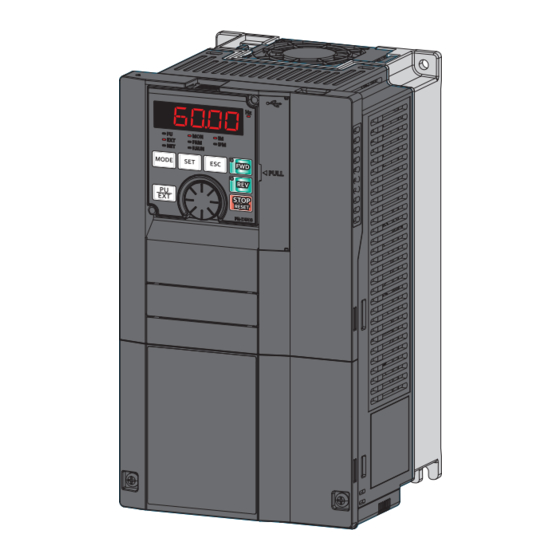
INVERTER
FR-F800
INSTALLATION GUIDELINE
FR-F820-00046(0.75K) to 04750(110K)(-E)
FR-F840-00023(0.75K) to 06830(315K)(-E)
FR-F842-07700(355K) to 12120(560K)(-E)
Thank you for choosing this Mitsubishi Electric Inverter.
This Installation guideline and the enclosed CD-ROM give handling information and precautions for use
of this product.
Do not use this product until you have a full knowledge of the equipment, the safety information and the
instructions.
Please forward this Installation guideline and the CD-ROM to the end user.
1
INSTALLATION AND INSTRUCTIONS..................................................................... 1
2
WIRING ...................................................................................................................... 4
3
FAILSAFE OF THE SYSTEM WHICH USES THE INVERTER............................... 24
4
PRECAUTIONS FOR USE OF THE INVERTER ..................................................... 25
5
BASIC OPERATION ................................................................................................ 27
6
TROUBLESHOOTING ............................................................................................. 44
7
SPECIFICATIONS ................................................................................................... 47
Art. no.: 281590
22062017
Version C
Version check
CONTENTS
800
Advertisement
Table of Contents

Related Manuals for Mitsubishi Electric FR-F820-00046


Summary of Contents for Mitsubishi Electric FR-F820-00046
-
Page 1: Table Of Contents
FR-F820-00046(0.75K) to 04750(110K)(-E) FR-F840-00023(0.75K) to 06830(315K)(-E) FR-F842-07700(355K) to 12120(560K)(-E) Thank you for choosing this Mitsubishi Electric Inverter. This Installation guideline and the enclosed CD-ROM give handling information and precautions for use of this product. Do not use this product until you have a full knowledge of the equipment, the safety information and the instructions. - Page 2 Safety stop function description For Maximum Safety Mitsubishi Electric transistorized inverters are not designed or manufactured to be used in equipment or systems in situations that can affect or endanger human life. When considering this product for operation in special applications such as machinery or systems used in passenger transportation, medical, aerospace, atomic power, electric power, or submarine repeating applications, please contact your nearest Mitsubishi Electric sales representative.
-
Page 3: Fire Prevention
A person who took a proper engineering training. Please note if you can take a proper engineering training at your local Mitsubishi Electric office. Such training may be available at your local Mitsubishi Electric office. Contact your local sales office for schedules and locations. - Page 4 2.9m/s² or less for the FR-F840-04320(185K) or higher If halogen-based materials (fluorine, chlorine, bromine, iodine, etc.) infiltrate into a Mitsubishi Electric product, the product will be damaged. Halogen-based materials are often included in fumigant, which is used to sterilize or disinfect wooden packages. When packaging, prevent residual fumigant components from being infiltrated into Mitsubishi Electric products, or use an alternative sterilization or disinfection method (heat disinfection, etc.) for packaging.
- Page 5 Operation WARNING When you have chosen the retry function, stay away from the equipment as it will restart suddenly after an alarm stop. Since pressing the key may not stop output depending on the function setting status, provide a circuit and switch separately to make an emergency stop (power off, mechanical brake operation for emergency stop, etc).
- Page 6 Disposing of the inverter CAUTION Treat as industrial waste. General instructions Many of the diagrams and drawings in instruction manuals show the inverter without a cover, or partially open. Never run the inverter in this status. Always replace the cover and follow instruction manuals when operating the inverter. For more details on the PM motor, refer to the Instruction Manual of the PM motor.
-
Page 7: Installation And Instructions
SLD is 110% of the rated current for 60s and 120% for 3s at surrounding air temperature of max. 40°C. The inverter model name used in this installation guide consists of the inverter model, e. g. FR-F820-00046-1 and the applicable motor capacity in brackets specified in [kW]. This approach helps for better understanding and for choosing the right motor. -
Page 8: Installation Of The Inverter
INSTALLATION AND INSTRUCTIONS 1.2 Installation of the inverter Installation on the enclosure Fix six positions for the FR-F840-04320(185K) or higher and for the FR-F842 models (separated converter type). Install the inverter on a strong surface securely with bolts. Leave enough clearances and take cooling measures. Avoid places where the inverter is subjected to direct sunlight, high temperature and high humidity. - Page 9 INSTALLATION AND INSTRUCTIONS 1.4 Accessory Fan cover fixing screws These screws are necessary for compliance with the EU Directives (refer to page 52). Capacity Screw size (mm) Quantity FR-F820-00105(2.2K) to FR-F820-00250(5.5K) M3 × 35 FR-F840-00083(3.7K), FR-F840-00126(5.5K) FR-F820-00340(7.5K) to FR-F820-00490(11K) M3 × 35 FR-F840-00170(7.5K) to FR-F840-00250(11K) FR-F820-00630(15K) to FR-F820-01250(30K) M4 ×...
-
Page 10: Wiring
2 WIRING 2.1 Terminal connection diagrams 2.1.1 FR-F820/F840(-E) CA type FR-F820-00770(18.5K)–01250(30K) FR-F840-00470(22K)–01800(75K) DC reactor (FR-HEL) DC reactor Brake unit (FR-HEL) (option) Source logic Brake unit (option) Jumper Main circuit terminal Earth Control circuit terminal Jumper Jumper Earth Inrush current limit circuit MCCB R/L1... - Page 11 WIRING For the FR-F820-03160(75K) or higher, and the FR-F840-01800(75K) or higher, always connect a DC reactor (FR-HEL), which is available as an option. (When selecting a DC reactor, refer to page 47, and select one suitable for the applicable motor capacity.) When a DC reactor is connected to the FR-F820-02330(55K) or lower or the FR-F840-01160(55K) or lower, if a jumper is installed across the terminals P1 and P/+, remove the jumper before installing the DC reactor.
- Page 12 WIRING FM type FR-F820-00770(18.5K)–01250(30K) FR-F840-00470(22K)–01800(75K) DC reactor (FR-HEL) DC reactor Brake unit (FR-HEL) (option) Sink logic Brake unit Main circuit terminal (option) Jumper Earth Control circuit terminal Earth Jumper Jumper Inrush current limit circuit MCCB R/L1 Inrush current 3-phase Motor limit circuit S/L2...
- Page 13 WIRING For the FR-F820-03160(75K) or higher, and the FR-F840-01800(75K) or higher always connect a DC reactor (FR-HEL), which is available as an option. (When selecting a DC reactor, refer to page 47, and select one suitable for the applicable motor capacity.) When a DC reactor is connected to the FR-F820-2330(55K) or lower or the FR-F840-01160(55K) or lower, if a jumper is installed across the terminals P1 and P/+, remove the jumper before installing the DC reactor.
- Page 14 WIRING 2.1.2 FR-F842(-E) CA type Source logic Main circuit terminal Control circuit terminal Brake unit (option) Converter unit Motor R/L1 S/L2 T/L3 Jumper R1/L11 Earth S1/L21 Main circuit Earth Control circuit Relay output Control input signals Forward rotation start Reverse rotation start Relay output 1 (Fault output)
- Page 15 WIRING The terminals R1/L11 and S1/L21 are connected to the terminals P/+ and N/– with a jumper respectively. When using separate power supply for the control circuit, remove the jumper between R1/L11 and S1/L21. No input voltage is allowed for these terminals.The function of these terminals can be changed with the input terminal assignment (Pr. 178 to Pr.
- Page 16 WIRING FM type Sink logic Main circuit terminal Control circuit terminal Brake unit (option) Converter unit Motor R/L1 S/L2 T/L3 Jumper R1/L11 Earth S1/L21 Main circuit Earth Control circuit Control input signals Relay output Forward rotation start Reverse rotation start Relay output 1 (Fault output) STP(STOP)
- Page 17 WIRING The terminals R1/L11 and S1/L21 are connected to the terminals P/+ and N/– with a jumper respectively. When using separate power supply for the control circuit, remove the jumper between R1/L11 and S1/L21. No input voltage is allowed for these terminals. The function of these terminals can be changed with the input terminal assignment (Pr.
-
Page 18: Terminal Layout And Wiring
WIRING 2.2 Main circuit terminal 2.2.1 Terminal layout and wiring FR-F820-00046(0.75K), 00077(1.5K) FR-F820-00105(2.2K) to 00250(5.5K) FR-F820-00340(7.5K), 00490(11K) FR-F840-00023(0.75K) to 00126(5.5K) FR-F840-00170(7.5K), 00250(11K) Jumper Jumper P/+ PR Jumper Jumper R1/L11 S1/L21 R/L1 S/L2 T/L3 Jumper R/L1 S/L2 T/L3 P/+ PR Jumper... - Page 19 WIRING The following diagram shows the positions of R1/L11, S1/L21, and the charge lamp. Charge lamp Jumper R1/L11 S1/L21 The terminals P3 and PR of the FR-F820-01540(37K) are not equipped with screws. Do not connect anything to these. For the FR-F840-01800(75K), a jumper is not installed across the terminals P1 and P/+. Always connect a DC reactor (FR-HEL), which is available as an option, across the terminals P1 and P/+.
- Page 20 WIRING 2.3 Wiring fundamentals 2.3.1 Cable size Select the recommended cable size to ensure that the voltage drop will be 2% max. If the wiring distance is long between the inverter and motor, the main circuit cable voltage drop will cause the motor torque to decrease especially at the output of a low frequency.
- Page 21 WIRING 400V class, FR-F842 (when input power supply is 440V) (For the applicable cables of the converter unit (FR-CC2) refer to the FR-CC2 Instruction Manual.) Cable sizes Crimping AWG/ terminal Applicable HIV, etc. [mm²] * PVC, etc. [mm²] * Terminal screw Tightening MCM * inverter type...
- Page 22 WIRING SLD rating (Pr. 570 "Multiple rating setting" = "0") 200V class, FR-F820 (when input power supply is 220V) Cable sizes Crimping terminal Applicable Terminal Tightening HIV, etc. [mm²] AWG/MCM PVC, etc. [mm²] screw inverter type torque R/L1, R/L1, Earth R/L1, R/L1, Earth...
- Page 23 WIRING 400V class, FR-F842 (when input power supply is 440V) (For the applicable cables of the converter unit (FR-CC2) refer to the FR-CC2 Instruction Manual.) Cable sizes Crimping AWG/ terminal Applicable HIV, etc. [mm²] * PVC, etc. [mm²] * Terminal screw Tightening MCM * inverter type...
- Page 24 WIRING 2.3.2 Total wiring length With general-purpose motor Connect one or more general-purpose motors within the total wiring length shown in the following table. FR-F820-00105(2.2K) or higher, Pr. 72 setting FR-F820-00046(0.75K), FR-F820-00077(1.5K), FR-F840-00052(2.2K) or higher, (carrier frequency) FR-F840-00023(0.75K) FR-F840-00038(1.5K) FR-F842...
-
Page 25: Control Circuit Terminals
WIRING 2.4 Control circuit terminals 2.4.1 Terminal layout ∗1 1 F/C +24 SD So SOC S1 S2 PC Recommended cable gauge: 0.3 to 0.75mm² 5 10E 10 SE SE SU IPF OL FU PC RL RM RH RT AU STP MRS RES SD SD STF STR JOG The terminal functions as the terminal FM for the FM type, and as the terminal CA for the CA type. -
Page 26: Wiring Precautions
WIRING (3) Insert the wires into a socket. When using a single wire or stranded wires without a blade terminal, push the open/close button all the way down with a flathead screwdriver, and insert the wire. Open/close button Flathead screwdriver Wire removal Pull the wire while pushing the open/close button all the way down firmly with a flathead screwdriver. - Page 27 WIRING 2.4.4 Control logic (sink/source) change Change the control logic of input signals as necessary. To change the control logic, change the jumper connector position on the control circuit board. Connect the jumper con- nector to the connector pin of the desired control logic. The control logic of input signals is initially set to the sink logic (SINK) for the FM type.
-
Page 28: Function Description
WIRING 2.5 Safety stop function 2.5.1 Function description The terminals related to the safety stop function are shown below. Terminal symbol Terminal function description Channel 1 Between S1 and SIC Open: In safety stop mode For input of the safety stop Short: Other than the safety stop mode Channel 2 Between S2 and SIC... - Page 29 WIRING 2.5.3 Safety stop function operation Output Output Internal *1, *2 Operation panel indication Input terminal Inverter operation terminal *8, *9 signal Input power safety circuit enable signal status SAFE E.SAF Output shutoff — — — Not displayed Not displayed (Safe state) Normal Drive enabled...
-
Page 30: Failsafe Of The System Which Uses The Inverter
Although Mitsubishi Electric assures best quality products, provide an interlock which uses inverter status output sig- nals to prevent accidents such as damage to machine when the inverter fails for some reason. -
Page 31: Precautions For Use Of The Inverter
4 PRECAUTIONS FOR USE OF THE INVERTER The FR-F800 series is a highly reliable product, but incorrect peripheral circuit making or operation/handling method may shorten the product life or damage the product. Before starting operation, always recheck the following items: Use crimping terminals with insulation sleeve to wire the power supply and motor. - Page 32 PRECAUTIONS FOR USE OF THE INVERTER Provide electrical and mechanical interlocks for MC1 and MC2 which are used for commercial power supply-inverter Interlock switch-over. R/L1 When the wiring is incorrect or if there is a commercial Power supply S/L2 power supply-inverter switch-over circuit as shown on the right, the inverter will be damaged by leakage current from T/L3 Undesirable current...
-
Page 33: Basic Operation
STOP/RESET key Resets the inverter when the protection function is activated. The setting dial of the Mitsubishi Electric inverters. The setting dial is used to change the frequency and parameter settings. Press the setting dial to perform the following operations: ¾... - Page 34 BASIC OPERATION 5.1.2 Basic operation (factory setting) Operation mode switchover/frequency setting External operation mode (At power-ON) PU operation mode PU JOG operation mode Flicker Example Frequency setting has been written Value change and completed! Output current monitor Output voltage monitor Parameter setting mode (At power-ON) Display the present setting...
-
Page 35: Parameter List
9999 MRS input selection 0, 2, 4 Differs according to capacities. 6%: FR-F820-00046(0.75K) and FR-F840-00023(0.75K) 4%: FR-F820-00077(1.5K) to 00167(3.7K) and FR-F840-00038(1.5K) to 00083(3.7K) 3%: FR-F820-00250(5.5K), 00340(7.5K), FR-F840-00126(5.5K) and 00170(7.5K) 2%: FR-F820-00490(11K) to 01540(37K) and FR-F840-00250(11K) to 00770(37K) 1.5%: FR-F820-01870(45K), 02330(55K), FR-F840-00930(45K) and 01160(55K) - Page 36 BASIC OPERATION Initial Initial Parameter Name Setting Range Parameter Name Setting Range Value Value 0 to 590Hz, Stall prevention Frequency jump 3B 9999 9999 operation reduction 0 to 590Hz 60/50Hz starting frequency Speed display 0, 1 to 9998 Number of retries at Up-to-frequency 0 to 10, 0 to 100%...
- Page 37 BASIC OPERATION Initial Initial Parameter Name Setting Range Parameter Name Setting Range Value Value Speed control gain PU communication 0 to 2 (Advanced magnetic 9999 CR/LF selection 0 to 200%, 9999 flux vector) Terminal 2 frequency 0 to 50Ω, setting gain 0 to 590Hz 60/50Hz 9999...
- Page 38 BASIC OPERATION Initial Initial Parameter Name Setting Range Parameter Name Setting Range Value Value 150/ User group Stall prevention level 9999 0 to 1999, 9999 0 to 400% at 10V input registration 120% 120/ User group clear 9999 Output current 0 to 1999, 9999 0 to 400% detection level...
- Page 39 BASIC OPERATION Initial Initial Parameter Name Setting Range Parameter Name Setting Range Value Value ABC1 terminal 0, 1, 2 , 3 to 5, Main circuit power 1 to 3600s, 600s 7, 8, 10 to 19, 25, function selection OFF waiting time 9999 26, 35, 39 to 42, Life alarm display...
- Page 40 BASIC OPERATION Initial Initial Parameter Name Setting Range Parameter Name Setting Range Value Value Overspeed detection 0 to 590Hz, 0, 1, 2 , 3 to 5, 9999 7, 8, 10 to 19, 25, level 9999 26, 35, 39 to 42, Input pulse division DO0 output selection 45 to 54, 57, 64,...
- Page 41 BASIC OPERATION Initial Initial Parameter Name Setting Range Parameter Name Setting Range Value Value Second motor NET mode operation 9999 0 to 100%, 9999 constant (X) command source 9999 0, 1, 5 , 9999 selection Second motor auto 0, 1, 11, 101 tuning setting/status PU mode operation 1 to 3, 5...
- Page 42 BASIC OPERATION Initial Initial Parameter Name Setting Range Parameter Name Setting Range Value Value Auxiliary motor First free thermal 0 to 590Hz, 9999 0 to 3 operation selection reduction frequency 3 9999 Motor connection Power failure stop 0 to 3 function selection external signal input 0, 1...
- Page 43 BASIC OPERATION Initial Initial Parameter Name Setting Range Parameter Name Setting Range Value Value Maintenance timer 2 Second starting warning output set 9999 resistance tuning 9999 0 to 9998, 9999 0 to 200%, 9999 time compensation Second motor Maintenance timer 3 0 (1 to 9998) 0 to 6000µs, magnetic pole...
- Page 44 BASIC OPERATION Initial Initial Parameter Name Setting Range Parameter Name Setting Range Value Value Second pre-charge 0 to 500A, 0 to 100%, 9999 upper detection level 9999 Torque current/Rated 9999 9999 PM motor current 0 to 3600A, Second pre-charge 0 to 3600s, 9999 time limit 9999...
- Page 45 BASIC OPERATION Initial Initial Parameter Name Setting Range Parameter Name Setting Range Value Value Power saving 0, 1 to 1000h, Terminal 1 gain 9999 150% 0 to 400% monitor average time 9999 command (torque) (920) Power saving Terminal 1 gain cumulative monitor 9999 0, 1, 10, 9999...
- Page 46 BASIC OPERATION Initial Initial Parameter Name Setting Range Parameter Name Setting Range Value Value Monitor with sign PU buzzer control 0, 1 1018 9999 0, 9999 selection PU contrast 0 to 63 Trace operation adjustment 1020 0 to 4 selection 0 to 3, 5 to 14, 1021 17, 18, 20, 23 to...
- Page 47 BASIC OPERATION Initial Initial Parameter Name Setting Range Parameter Name Setting Range Value Value Digital trigger Second output 1046 1 to 8 1149 channel interruption cancel 1000% 900 to 1100% level Digital trigger 1047 0, 1 1150 operation selection User parameters Display-off waiting 0 to 65535 1048...
- Page 48 BASIC OPERATION Initial Initial Parameter Name Setting Range Parameter Name Setting Range Value Value 1434 PID measured value Ethernet IP address 1 0 to 255 1372 control set point 0 to 50% 1435 Ethernet IP address 2 0 to 255 change amount 1436 Ethernet IP address 3...
- Page 49 BASIC OPERATION Initial Initial Parameter Name Setting Range Parameter Name Setting Range Value Value Number of cleaning Load characteristics 0 to 400%, 1469 1485 9999 0 to 255 times monitor load reference 5 8888, 9999 Number of cleaning Load characteristics 1470 1486 0 to 255...
-
Page 50: Troubleshooting
6 TROUBLESHOOTING When a fault occurs in the inverter, the protective function activates, and the PU display automatically changes to one of the fault or alarm indications listed on page 45. If the fault does not correspond to any of the following errors or if you have any other problem, please contact your sales representative. -
Page 51: Reset Method Of Protective Function
TROUBLESHOOTING 6.1 Reset method of protective function The inverter can be reset by performing any of the following operations. Note that the internal thermal integrated value of the electronic thermal relay function and the number of retries are cleared (erased) by resetting the inverter. Inverter recovers about 1s after reset is cancelled. - Page 52 TROUBLESHOOTING Data Data Operation panel indication Name Operation panel indication Name code code Inverter overload trip (electronic Operation panel power supply E.THT thermal relay function) (H30) short circuit/ E.CTE RS-485 terminal power supply (HC1) Motor overload trip (electronic E.THM short circuit (FR-F800-E (H31) thermal relay function) without RS-485 terminals)
-
Page 53: Specifications
Forced air cooling Weight [kg] The applicable motor capacity indicated is the maximum capacity applicable for use of the Mitsubishi Electric 4-pole standard motor. The rated output capacity indicated assumes that the output voltage is 220V. The % value of the overload current rating indicated is the ratio of the overload current to the inverter's rated output current. For repeated duty, allow time for the inverter and motor to return to or below the temperatures under 100% load. - Page 54 8.3 8.3 166 166 166 The applicable motor capacity indicated is the maximum capacity applicable for use of the Mitsubishi Electric 4-pole standard motor. The rated output capacity indicated assumes that the output voltage is 440V. The % value of the overload current rating indicated is the ratio of the overload current to the inverter's rated output current. For repeated duty, allow time for the inverter and motor to return to or below the temperatures under 100% load.
- Page 55 Forced air cooling Weight [kg] The applicable motor capacity indicated is the maximum capacity applicable for use of the Mitsubishi Electric 4-pole standard motor. The rated output capacity indicated assumes that the output voltage is 440V. The % value of the overload current rating indicated is the ratio of the overload current to the inverter's rated output current. For repeated duty, allow time for the inverter and motor to return to or below the temperatures under 100% load.
-
Page 56: Outline Dimensions
SPECIFICATIONS 7.2 Outline dimensions FR-F820-00046(0.75K) to 04750(110K) FR-F840-04320(185K) to 06830(315K) FR-A820-00046(0.4K) to 04750(90K) FR-A840-04320(160K) to 06830(280K) FR-F840-00023(0.75K) to 03610(160K) FR-A840-00023(0.4K) to 03610(132K) 3-φC 2-φC (Unit: mm) Inverter Type FR-F820-00046(0.75K) FR-F820-00077(1.5K) FR-F820-00105(2.2K) FR-F820-00167(3.7K) FR-F820-00250(5.5K) FR-F820-00340(7.5K) FR-F820-00490(11K) FR-F820-00630(15K) FR-F820-00770(18.5K) FR-F820-00930(22K) FR-F820-01250(30K) FR-F820-01540(37K) - Page 57 SPECIFICATIONS FR-F842-07700(355K) to 12120(560K) 3-ØC (Unit: mm) Inverter type FR-F842-07700(355K) 1330 1300 FR-F842-08660(400K) FR-F842-09620(450K) FR-F842-10940(500K) 1580 1550 FR-F842-12120(560K) For dimensions of the converter unit (FR-CC2) refer to the FR-CC2 Instruction Manual.
-
Page 58: Aappendix
CE marking. The authorized representative in the EU The authorized representative in the EU is shown below: Name: Mitsubishi Electric Europe B.V. Address: Mitsubishi-Electric-Platz 1, 40882 Ratingen, Germany A.1.1 EMC Directive We declare that this inverter conforms with the EMC Directive and affix the CE marking on the inverter. - Page 59 APPENDIX A.1.2 Low Voltage Directive We have self-confirmed our inverters as products compliant to the Low Voltage Directive (conforming standard EN 61800-5-1) and place the CE mark on the inverters. Outline of instructions Do not use an earth leakage current breaker as an electric shock protector without connecting the equipment to the earth.
- Page 60 APPENDIX Wiring protection For installation Class T, Class J, Class CC, or Class L fuse, or UL 489 Molded Case Circuit Breaker (MCCB) according to the local directives must be provided. 00046 00077 00105 00167 00250 00340 00490 00630 00770 00930 01250 01540...
- Page 61 Manufacturer Rated voltage, V AC MMP-T32 Mitsubishi Electric Corp. 480Y/277 Suitable for use in a circuit capable of delivering not more than 50 or 25 kA rms symmetrical amperes, 480Y/277 volts maximum when protected by the type E combination motor controllers indicated in the above table.
- Page 62 It is not the percentage to the motor rated current. When you set the electronic thermal relay function Region for dedicated to the Mitsubishi Electric constant-torque motor, transistor this characteristic curve applies to operation at 6 Hz or protection higher.
- Page 64 Vernon Hills, IL 60061 Phone: +1 (847) 478-2100 Fax: +1 (847) 478-0328 Mitsubishi Electric Europe B.V. / FA - European Business Group / Mitsubishi-Electric-Platz 1 / D-40882 Ratingen / Germany / Tel.: +49(0)2102-4860 / Fax: +49(0)2102-4861120 / info@mitsubishi-automation.com / https://eu3a.mitsubishielectric.com...
Need help?
Do you have a question about the FR-F820-00046 and is the answer not in the manual?
Questions and answers