
Related Manuals for ABB AC500 V3


Summary of Contents for ABB AC500 V3
- Page 1 HARDWARE MANUAL PLC Automation System assembly and device specifications AC500 V3, AC500-eCo V3, AC500-XC V3...
-
Page 2: Table Of Contents
— Table of contents Device specifications............................4 1.1 Status LEDs, display and control elements....................4 1.2 Terminal bases (AC500 standard)......................4 1.2.1 TB56xx for AC500 V3 products....................4 1.3 Processor modules..........................14 1.3.1 AC500-eCo..........................14 1.3.2 AC500 (standard)........................90 1.4 Communication modules (AC500 standard)..................101 1.4.1... - Page 3 Table of contents 2.5.4 Connection and wiring......................943 2.5.5 Handling of accessories......................946 2.6 AC500 (Standard)..........................971 2.6.1 System data AC500....................... 971 2.6.2 Mechanical dimensions......................976 2.6.3 Mounting and demounting..................... 981 2.6.4 Connection and wiring......................989 2.6.5 Handling of accessories....................... 1001 2.7 AC500-XC............................
-
Page 4: Device Specifications
Device specifications Terminal bases (AC500 standard) > TB56xx for AC500 V3 products — 1 Device specifications 1.1 Status LEDs, display and control elements Depending on the device type, various operating elements provided on the front panel can be used to control the devices of the PLC system and/or to change the operating mode. - Page 5 Device specifications Terminal bases (AC500 standard) > TB56xx for AC500 V3 products Processor module PM5630 PM5650 PM5670 PM5675 TB5640-2ETH 4 slots 4 slots 4 slots TB5660-2ETH 6 slots 6 slots Remarks: The slots can be used for connecting communication modules or AC500-S modules. Note that only one AC500-S module can be connected at one terminal base.
- Page 6 Device specifications Terminal bases (AC500 standard) > TB56xx for AC500 V3 products XC version XC = eXtreme Conditions Extreme conditions Terminal bases for use in extreme ambient conditions have no sign for XC version. The figure 3 in the Part no. 1SAP3... (label) identifies the XC version.
- Page 7 Device specifications Terminal bases (AC500 standard) > TB56xx for AC500 V3 products 1.2.1.2 Connections 1.2.1.2.1 I/O bus The I/O bus is the I/O data bus for the I/O modules. Through this bus, I/O and diagnosis data are transferred between the processor module and the I/O modules. Up to 10 I/O modules can Ä...
- Page 8 Device specifications Terminal bases (AC500 standard) > TB56xx for AC500 V3 products NOTICE! Risk of damaging the terminal base! Terminal base can be damaged by connecting the power supply terminal block (L+/M) to COM1. Make sure that the COM1 terminal block is always connected to the terminal base even if you do not use COM1 to prevent this.
- Page 9 Device specifications Terminal bases (AC500 standard) > TB56xx for AC500 V3 products Pin assignment Signal Interface Description (RS-485 / Terminator P RS-485 Terminator P RS-232) RxD/TxD-P RS-485 Receive/Transmit, positive RxD/TxD-N RS-485 Receive/Transmit, negative Terminator N RS-485 Terminator N RS-232 Request to send...
- Page 10 Ä Chapter 1.8.3.4 “TA535 - Protective caps for XC devices” devices. on page 906 See supported protocols and used Ethernet ports for AC500 V3 products: . See communication via Modbus for AC500 V3 products: . See communication via Modbus for AC500 V3 products: .
- Page 11 Device specifications Terminal bases (AC500 standard) > TB56xx for AC500 V3 products Pin assignment Interface Signal Description CAN_GND CAN reference potential CAN_L Bus line, receive/transmit line, CAN_SHLD Shield of the bus line CAN_H Bus line, receive/transmit line, HIGH Not connected...
- Page 12 Device specifications Terminal bases (AC500 standard) > TB56xx for AC500 V3 products Parameter Value Connection of the supply voltage 24 V Removable 5-pin terminal block spring type DC at the terminal base of the processor module Max. current consumption from 24 V DC TB5600: 0.25 A...
- Page 13 Device specifications Terminal bases (AC500 standard) > TB56xx for AC500 V3 products 1.2.1.4 Ordering data Part no. Description Product life cycle phase *) 1SAP 110 300 R0278 TB5600-2ETH, terminal base AC500, Active slots: 1 processor module, 2 Ethernet RJ45, 1 CAN connector...
-
Page 14: Processor Modules
Device specifications Processor modules > AC500-eCo Processor module PM5630 PM5650 PM5670 PM5675 TB5660-2ETH 6 slots 6 slots Remarks: The slots can be used for connecting communication modules or AC500-S modules. Note that only one AC500-S module can be connected at one terminal base. ) PM567x must have an index ≥... - Page 15 Device specifications Processor modules > AC500-eCo Processor Global user Configurable Digital Digital out- Power Ethernet Option modules memory input/output inputs puts supply interfaces board slots Basic CPUs PM5012-T-ETH 1 MB 4 (Tran- 24 V DC sistor) thereof 256 kB for user pro- gram code and data...
- Page 16 Device specifications Processor modules > AC500-eCo Processor Global user Configurable Digital Digital out- Power Ethernet Option modules memory input/output inputs puts supply interfaces board slots PM5072-T-2ETH 8 MB 2 (Transistor) 8 (Tran- 24 V DC sistor) thereof 1 MB for user pro- gram code and data dynamically...
- Page 17 Device specifications Processor modules > AC500-eCo 10 13-pin terminal block for onboard I/Os 11 12-pin terminal block for onboard I/Os (not available on PM5012-x-ETH) 12 12 LEDs to display the states of the signals 13 10 LEDs to display the states of the signals 14 Cable fixing accessory TA5301-CFA on the top of the housing (optional) The processor module is shown with pluggable terminal blocks.
- Page 18 Device specifications Processor modules > AC500-eCo 1.3.1.1.2 Assortment Processor Total Allocated Cycle Numer Number Type of Config- Number Max. module max- global time for digital digital digital urable of option number user 1000 inputs outputs outputs digital board of I/O memory instructio inputs/...
- Page 19 Device specifications Processor modules > AC500-eCo Option board Depending on the processor module variants, an additional option board can be connected to slot interface the option board slot to extend the feature of the processor module . Serial interface RS-232 communication interface is available by using option board: ●...
- Page 20 Device specifications Processor modules > AC500-eCo Basic CPU (PM5012) Standard CPUs (PM5032, PM5052) and Pro CPUs (PM5072) Spring type Screw type Spring type Screw type TA5211-TSPF-B TA5211-TSCL-B TA5212-TSPF TA5212-TSCL Further information on the terminal blocks concerning power supply and onboard inputs/outputs are provided under pluggable connectors for screw and spring connection Ä...
- Page 21 Device specifications Processor modules > AC500-eCo State Color LED = ON LED = OFF LED flashing Error indication An error occurred No errors or only Fast flashing (4 warnings Hz) displays encountered (E4 together with the errors). RUN LED a cur- rently running The LED firmware-upgrade...
- Page 22 Device specifications Processor modules > AC500-eCo State Color LED = ON LED = OFF LED flashing Slow flashing (1 Hz): The firmware update from the memory card has been completed successfully Boot project is being updated. Slow flashing (0.5 Hz) together with MOD1 LED ON: Mode1: Boot...
- Page 23 Device specifications Processor modules > AC500-eCo Processor State Color LED = ON LED = OFF module PM5072- O0..O7 Transistor Yellow Output is ON Output is OFF T-2ETHW output C12, C13 Digital configu- Yellow Input/Output Input/Output is rable input/ is ON output Ethernet state Table 8: State LEDs at Ethernet connector...
- Page 24 Device specifications Processor modules > AC500-eCo Intended purpose Table 9: Numbers and types of the onboard I/Os Processor module No. and type of dig- No. and type of dig- No. and type of con- ital inputs ital outputs figurable inputs/out- puts PM5012-T-ETH None...
- Page 25 Device specifications Processor modules > AC500-eCo Functionality Parameter Value PM5012-T-ETH PM5012-R-ETH PM5032-T-ETH PM5032-R-ETH PM5052-T-ETH PM5052-R-ETH PM5072- T-2ETH(W) Digital inputs Functionality of 6 DI fast input 24 V DC (max. 5 4 DI fast input 24 V DC (max. 200 digital inputs kHz) kHz) (encoder, fast...
- Page 26 Device specifications Processor modules > AC500-eCo Parameter Value PM5012-T-ETH PM5012-R-ETH PM5032-T-ETH PM5032-R-ETH PM5052-T-ETH PM5052-R-ETH PM5072- T-2ETH(W) Functionality of 4 fast output 4 DO-R 4 fast output 6 DO-R digital outputs DO-T DO-T 24 V DC / 240 V 24 V DC / 240 V 24 V DC/0.5 A AC 2A in 2 24 V DC (100...
- Page 27 Device specifications Processor modules > AC500-eCo Parameter Value PM5012-T-ETH PM5012-R-ETH PM5032-T-ETH PM5032-R-ETH PM5052-T-ETH PM5052-R-ETH PM5072- T-2ETH(W) Digital inputs/ outputs, configurable Functionality of 2 DC 24 V DC 2 DC 24 V DC digital inputs/ ● 2 standard usable as outputs, I/Os configurable ●...
- Page 28 Device specifications Processor modules > AC500-eCo NOTICE! Risk of damaging the PLC modules! Overvoltages and short circuits might damage the PLC modules. – Make sure that all voltage sources (supply voltage and process supply voltage) are switched off before you begin with operations on the system. –...
- Page 29 Device specifications Processor modules > AC500-eCo Terminal Signal Description Normally-open relay contact of the output NO2 Normally-open relay contact of the output NO3 R2..3 Output common for signals NO2 to NO3 Table 12: Assignment of the terminals for PM5032-T-ETH, PM5052-T-ETH and PM5072- T-2ETH(W): Terminal Signal...
- Page 30 Device specifications Processor modules > AC500-eCo Terminal Signal Description Process supply voltage UP +24 V DC Process supply voltage ZP 0 V DC Table 13: Assignment of the terminals for PM5032-R-ETH and PM5052-R-ETH: Terminal Signal Description COM 0..11 Input common for digital input signals I0 to I11 Digital input signal I0 (max.
- Page 31 Device specifications Processor modules > AC500-eCo Block diagrams The following block diagram shows the internal structure of the onboard I/Os. PM5012-T-ETH PM5012-R-ETH PM5032-ETH PM5032-R-ETH PM5052-T-ETH PM5052-R-ETH PM5072-T-2ETH(W) 2022/01/31 3ADR010278, 3, en_US...
- Page 32 Device specifications Processor modules > AC500-eCo Connection of the digital inputs The digital inputs can be used as source inputs or as sink inputs. NOTICE! Risk of malfunctions in the plant! A ground fault, e. g. caused by a damaged cable insulation, can bridge switches accidentally.
- Page 33 Device specifications Processor modules > AC500-eCo Connection of the digital transistor outputs (PM50xx-T-ETH only) Fig. 2: Connection of digital transistor outputs and configurable digital inputs/outputs C12 used as configurable digital input C13 used as configurable digital transistor output CAUTION! Risk of damaging the processor module! The outputs are not protected against short circuit and overload.
- Page 34 Device specifications Processor modules > AC500-eCo Fig. 3: Connection of digital relay outputs and configurable digital inputs/outputs C12 used as configurable digital input C13 used as configurable digital transistor output WARNING! Risk of death by electric shock! Hazardous voltages can be present at the terminals of the module. Make sure that all voltage sources (supply voltage and process supply voltage) are switched off before you begin with operations on the system.
- Page 35 Device specifications Processor modules > AC500-eCo I/O configuration The configuration data of the onboard I/Os is stored in the processor modules PM50x2. See PLC configuration: Parameterization For information about parameterization, refer to the description for onboard I/Os for processor modules PM50x2. See PLC configuration: and Diagnosis No diagnosis is generated for the onboard I/O.
- Page 36 Device specifications Processor modules > AC500-eCo Parameter Value Indication of the input signals 1 yellow LED per channel; the LED is ON when the input signal is high (signal 1) and the module's logic is in operation Input type according to EN 61131-2 Type 1 source Type 1 sink Input signal voltage...
- Page 37 Device specifications Processor modules > AC500-eCo Further information: Operating modes of the fast counter: Configurarion of the fast counter: Parameter PM5012-T-ETH PM5012-R-ETH PM5032-T-ETH PM5032-R- PM5052-T-ETH PM5052-R- PM5072- T-2ETH Fast counter Useable inputs Fast input DI4 ... DI5 DI4 ... DI5 max.
- Page 38 Device specifications Processor modules > AC500-eCo Parameter PM5012-T-ETH PM5012-R-ETH PM5032-T-ETH PM5032-R- PM5052-T-ETH PM5052-R- PM5072- T-2ETH Fast input DI0 ... DI3 DI0 ... DI3 max. 5 kHz Fast input, DI6 ... DI7 DI6 ... DI7 max. 100 kHz When using the When using the A/B encoder on A/B encoder on...
- Page 39 Device specifications Processor modules > AC500-eCo Parameter Value Output current limitation Resistance to feedback against 24 V DC Connection of 2 outputs in parallel Not possible Max. cable length *) Shielded On request Unshielded On request *) For fast inputs and fast outputs including PTO and PWM, a shielded cable must be used and the max.
- Page 40 Device specifications Processor modules > AC500-eCo Parameter Value Shielded On request Unshielded On request *) For fast inputs and fast outputs including PTO and PWM, a shielded cable must be used and the max. cable length is 50 m. Technical data of the digital relay outputs Table 17: PM5012-R-ETH Parameter Value...
- Page 41 Device specifications Processor modules > AC500-eCo Parameter Value With resistive loads Max. 1 Hz With inductive loads On request With lamp loads On request Short-circuit-proof / Overload-proof No, should be provided by an external fuse or circuit breaker Rated protection fuse (for each channel) On request Overload message Output current limitation...
- Page 42 Device specifications Processor modules > AC500-eCo Parameter Value Output current Rated current per channel (max.) 2.0 A (24 V DC resistance and general use, 100 V AC...240 V AC, resistance, general use and pilot duty) Rated current per group (max.) Rated current (all channels together, max.) 12 A Demagnetization when inductive loads are...
- Page 43 Device specifications Processor modules > AC500-eCo Technical data of the PTO outputs Parameter PM5012-T-ETH PM5012-R-ETH PM5032-T-ETH PM5032-R- PM5052-T-ETH PM5052-R- PM5072- T-2ETH Useable outputs pair of output Fast output, DO4 … DO7 DC12 … DC13 max. 100 kHz For 2 PTO 200 kHz *) Pulse/ Direction or CC/Ccw modes...
- Page 44 Device specifications Processor modules > AC500-eCo Ordering data Table 19: Processor modules for AC500-eCo V3 Part no. Description Product life cycle phase *) 1SAP 122 600 R0072 Basic CPU PM5012-T-ETH, AC500- Active eCo V3 processor module, programmable logic controller 1 MB, 6DI/4DO-Transistor, Ethernet, 24 V DC, 1 option board slot 1SAP 122 700 R0072 Basic CPU PM5012-R-ETH, AC500- Active...
- Page 45 Device specifications Processor modules > AC500-eCo Table 20: Accessories for AC500-eCo V3 Part no. Description 1SAP 187 000 R0001 TA5101-4DI: AC500, option board for digital I/O extension, 4DI 24 V DC, spring/cable front terminal 3.50 mm pitch 1SAP 187 000 R0002 TA5105-4DOT: AC500, option board for digital I/O extension, 4DO-T 24 V DC / 0.5 A, spring/cable front terminal 3.50 mm pitch 1SAP 187 000 R0003...
- Page 46 Device specifications Processor modules > AC500-eCo Part no. Description 1SAP 187 400 R0013 TA5220-SPF6: spring terminal block, removable, 6-pin, spring front, cable front, 6 pieces per packing unit 1SAP 187 400 R0014 TA5220-SPF7: spring terminal block, removable, 7-pin, spring front, cable front, 6 pieces per packing unit 1SAP 187 400 R0015 TA5220-SPF8: spring terminal block, removable, 8-pin, spring front,...
- Page 47 Device specifications Processor modules > AC500-eCo Parameter Value PM5012 PM5032 PM5052 PM5072 Thereof user web server memory for no web 1.5 MB 3.2 MB 7 MB web visualization max. User data memory saved in FLASH 8 kB 32 kB 100 kB VAR_RETAIN persistent 4 kB 16 kB...
- Page 48 Device specifications Processor modules > AC500-eCo Data of I/Os PM5012-x-ETH PM5032-x-ETH PM5052-x-ETH PM5072-T-2ETH Type of digital PM5012-T-ETH: PM5032-T-ETH: PM5052-T-ETH: PM5072-T-2ETH: outputs Transistor Transistor Transistor Transistor PM5012-R-ETH: PM5032-R-ETH: PM5052-R-ETH: Relay Relay Relay Channels for transistor version (5 kHz standard (incl. 4 fast outputs for standard or 4 PWM/2 PTO and PWM) (100 kHz/200 kHz), 4 standard outputs (5 kHz)) Channels digital...
- Page 49 Device specifications Processor modules > AC500-eCo Data of I/Os PM5012-x-ETH PM5032-x-ETH PM5052-x-ETH PM5072-T-2ETH Digital inputs Onboard I/O only 128 B 1 kB Digital outputs 128 B 1 kB Number of Depending on the fieldbus used decentralized inputs and out- puts Internal interfaces Serial COMx Optional, use a...
- Page 50 Device specifications Processor modules > AC500-eCo Data of I/Os PM5012-x-ETH PM5032-x-ETH PM5052-x-ETH PM5072-T-2ETH IEC 61850 MMS Yes (max. 1000 server/goose data attributes) pub/sub EtherNet/IP Yes (in preparation) adapter/scanner 1.3.1.1.9 Ordering Data Table 21: Processor modules for AC500-eCo V3 Part no. Description Product life cycle phase *) 1SAP 122 600 R0072 Basic CPU PM5012-T-ETH, AC500-...
- Page 51 Device specifications Processor modules > AC500-eCo *) Modules in lifecycle Classic are available from stock but not recommended for planning and commissioning of new installations. Table 22: Accessories for AC500-eCo V3 Part no. Description 1SAP 187 000 R0001 TA5101-4DI: AC500, option board for digital I/O extension, 4DI 24 V DC, spring/cable front terminal 3.50 mm pitch 1SAP 187 000 R0002 TA5105-4DOT: AC500, option board for digital I/O extension, 4DO-T...
- Page 52 Device specifications Processor modules > AC500-eCo Part no. Description 1SAP 182 800 R0001 TA543: screw mounting accessory, 20 pieces per packing unit 1SAP 187 500 R0003 TA5301-CFA: cable fixing part accessory, 20 pieces per packing unit Spare parts 1SAP 187 400 R0012 TA5220-SPF5: spring terminal block, removable, 5-pin, spring front, cable front, 6 pieces per packing unit 1SAP 187 400 R0013...
- Page 53 Device specifications Processor modules > AC500-eCo Intended pur- The device is used as an optional I/O extension module for AC500-eCo V3 CPUs (PM50x2). pose The inputs/outputs are group-wise galvanically isolated from each other. All other circuitry of the module is galvanically isolated from the inputs/outputs. Functionality Parameter Value...
- Page 54 Device specifications Processor modules > AC500-eCo WARNING! Removal/Insertion under power The devices are not designed for removal or insertion under power. Because of unforeseeable consequences, it is not allowed to plug or unplug devices with the power being ON. Make sure that all voltage sources (supply and process voltage) are switched off before you –...
- Page 55 Device specifications Processor modules > AC500-eCo I/O configura- The module itself does not store configuration data. It receives its parameterization data from tion the CPU module during power-up of the system. Hence, replacing optional modules is possible without any re-parameterization via software. Parameteriza- The arrangement of the parameter data is performed with Automation Builder software.
- Page 56 Device specifications Processor modules > AC500-eCo Technical data Ä Chapter 2.5.1 “System data AC500-eCo V3” The system data of AC500-eCo V3 apply on page 925 Only additional details are therefore documented below. Parameter Value Galvanic isolation Yes, between the input group and the rest of the module Isolated groups 1 (4 channels per group)
- Page 57 Device specifications Processor modules > AC500-eCo Parameter Value Input delay (0->1 or 1->0) Typ. 8 ms Input data length 1 byte Max. cable length Shielded On request Unshielded On request Ordering data Part no. Description Product life cycle phase *) 1SAP 187 000 R0001 TA5101-4DI: AC500, option board for Active digital I/O extension, 4DI 24 V DC,...
- Page 58 Device specifications Processor modules > AC500-eCo 4 yellow LEDs to display the signal states of the inputs O0 to O3 Allocation of signal name 7-pin terminal block for output signals NOTICE! Risk of damaging the PLC modules! Overvoltages and short circuits might damage the PLC modules. –...
- Page 59 Device specifications Processor modules > AC500-eCo Table 26: Assignment of the terminals: Terminal Signal Description Not connected Output signal O0 Output signal O1 Output signal O2 Output signal O3 Process supply voltage UP +24 V DC Process supply voltage ZP 0 V DC The internal power supply voltage for the module's circuitry is carried out via the connection to CPU.
- Page 60 Device specifications Processor modules > AC500-eCo NOTICE! Risk of damaging the PLC modules! Overvoltages and short circuits might damage the PLC modules. – Make sure that all voltage sources (supply voltage and process supply voltage) are switched off before you begin with operations on the system. –...
- Page 61 Device specifications Processor modules > AC500-eCo In the device tree, double-click the desired option board. Select the “TA51xx Parameters” tab to edit the parameterization of the desired option board. Diagnosis In the device tree, double-click the desired option board. Select the “Diagnosis” tab to view the diagnosis messages of the desired option board. Table 27: Diagnosis messages Device Severity...
- Page 62 Device specifications Processor modules > AC500-eCo State LEDs State Color LED = OFF LED = ON Outputs O0...O3 Digital output Yellow Output is OFF Output is ON (The output voltage (normally 24 V DC) is only displayed if UP/ZP and L+/M (supply voltages for the module) are switched ON)
- Page 63 Device specifications Processor modules > AC500-eCo Parameter Value Common power supply voltage Terminal 6 (positive pole of the process voltage, signal name UP) Reference potential for the channels O0 to Terminal 7 (negative pole of the process voltage, signal name ZP) Indication of the output signals 1 yellow LED per channel;...
- Page 64 Device specifications Processor modules > AC500-eCo Ordering data Part no. Description Product life cycle phase *) 1SAP 187 000 R0002 TA5105-4DOT: AC500, option board Active for digital I/O extension, 4DO-T 24 V DC / 0.5 A, spring/cable front terminal 3.50 mm pitch Spare parts 1SAP 187 400 R0014 TA5220-SPF7: spring terminal block,...
- Page 65 Device specifications Processor modules > AC500-eCo NOTICE! Risk of damaging the PLC modules! Overvoltages and short circuits might damage the PLC modules. – Make sure that all voltage sources (supply voltage and process supply voltage) are switched off before you begin with operations on the system. –...
- Page 66 Device specifications Processor modules > AC500-eCo Terminal Signal Description Input signal I1 Output signal O0 Output signal O1 Process supply voltage UP +24 V DC Process supply voltage ZP 0 V DC The internal power supply voltage for the module's circuitry is carried out via the connection to CPU.
- Page 67 Device specifications Processor modules > AC500-eCo The following figure shows the connection for inputs of the option board for digital I/O extension TA5110-2DI2DOT: Sink inputs of TA5110-2DI2DOT Source inputs of TA5110-2DI2DOT The following figure shows the connection for outputs of the option board for digital I/O exten- sion TA5110-2DI2DOT: NOTICE! Risk of malfunctions in the plant!
- Page 68 Device specifications Processor modules > AC500-eCo Parameteriza- The arrangement of the parameter data is performed with Automation Builder software. tion In the device tree, double-click the desired option board. Select the “TA51xx Parameters” tab to edit the parameterization of the desired option board.
- Page 69 Device specifications Processor modules > AC500-eCo Technical data Ä Chapter 2.5.1 “System data AC500-eCo V3” The system data of AC500-eCo V3 apply on page 925 Only additional details are therefore documented below. Parameter Value Process supply voltage UP Connections Terminal 6 for UP (+24 V DC) and ter- minal 7 for ZP (0 V DC) Rated value 24 V DC...
- Page 70 Device specifications Processor modules > AC500-eCo Parameter Value Undefined signal -15 V...+ 5 V +5 V...+15 V Signal 1 -30 V...-15 V +15 V...+30 V Ripple with signal 0 -5 V...+3 V -3 V...+5 V Ripple with signal 1 -30 V...-15 V +15 V...+30 V Input current per channel Input voltage +24 V...
- Page 71 Device specifications Processor modules > AC500-eCo Parameter Value Output type Non-protected Protection type External fuse on each channel Rated protection fuse (for each channel) On request Demagnetization when inductive loads are Must be performed externally according to switched off driven load specification Switching Frequencies With inductive loads On request...
- Page 72 Device specifications Processor modules > AC500-eCo 1.3.1.2.4 TA5130-KNXPB - Option board KNX adress push button State LED Allocation of signal name Connector For more information about TA5130-KNXPB, please refer to the Automation Builder online help. Intended pur- pose This option board is only intended to be used with PM5072-T-2ETH(W). This option board can only be used once on one slot at a time! The option board is not supported by other AC500-eCo V3 PLCs.
- Page 73 Device specifications Processor modules > AC500-eCo State LEDs Signal Color State Description Programming state Technical data Ä Chapter 2.5.1 “System data AC500-eCo V3” The system data of AC500-eCo V3 apply on page 925 Only additional details are therefore documented below. Parameter Value Usable CPUs...
- Page 74 Device specifications Processor modules > AC500-eCo 1.3.1.2.5 TA5131-RTC - Option board for real-time clock TA5131-RTC option board Intended pur- pose This option board is only for the basic CPUs PM5012-T-ETH and PM5012-R- ETH. All other AC500-eCo V3 CPUs have the real-time clock already integrated. Information can be found in the chapter system technology: see Functionality Information can be found in the chapter system technology: see...
- Page 75 Device specifications Processor modules > AC500-eCo Technical data Ä Chapter 2.5.1 “System data AC500-eCo V3” The system data of AC500-eCo V3 apply on page 925 Only additional details are therefore documented below. Parameter Value Buffering time 7 days at room temperature Usable CPUs PM5012 Internal power supply...
- Page 76 Device specifications Processor modules > AC500-eCo Intended pur- Option board for COMx serial communication TA5141-RS232I is equipped with 1 RS-232 serial pose interface with handshake. Connections Serial interfaces NOTICE! Damage to the serial communication interface by using 5-pin terminal block of the TA5101-4DI! If the 5-pin terminal block of the TA5101-4DI option board is plugged into a option board for COMx serial communication TA5141-RS232I, TA5142-RS485I or TA5142-RS485, the communication interface will be damaged by the 24 V.
- Page 77 Device specifications Processor modules > AC500-eCo State LEDs Signal Color State Description Yellow ON (blinking) Transmitting Yellow ON (blinking) Receiving Technical data Ä Chapter 2.5.1 “System data AC500-eCo V3” The system data of AC500-eCo V3 apply on page 925 Only additional details are therefore documented below. Parameter Value Protocol...
- Page 78 Device specifications Processor modules > AC500-eCo **) The needed spring terminal block is always delivered with the option board. The terminal block listed in the table is for spare part only if needed. 1.3.1.2.7 TA5142-RS485I - Option board for COMx serial communication 2 LEDs for communication state display (TxD and RxD) 2 LEDs for termination state display Allocation of signal name...
- Page 79 Device specifications Processor modules > AC500-eCo Table 34: TA5142-RS485(I) Serial interface Signal internally connected to A2 internally connected to B2 internally connected to A1 internally connected to B1 Protocols Protocol Description Modbus Modbus RTU, master or slave CAA SerialCom Support for blocks contained in the CAA_SerialCom.lib library Bus cable Bus line Construction...
- Page 80 Device specifications Processor modules > AC500-eCo Termination resistance settings Pull-up and pull-down settings Table 35: Configuration Settings on the module State of Internal wiring Description LEDs diagram Master at the bus line end, pull-up and pull-down activated, bus termination 120 Ω 3ADR010278, 3, en_US 2022/01/31...
- Page 81 Device specifications Processor modules > AC500-eCo Settings on the module State of Internal wiring Description LEDs diagram Master within the bus line, pull-up and pull-down activated Slave at the bus line end, bus termination 120 Ω 2022/01/31 3ADR010278, 3, en_US...
- Page 82 Device specifications Processor modules > AC500-eCo Settings on the module State of Internal wiring Description LEDs diagram Slave within the bus line Parameteriza- The arrangement of the parameter data is performed with Automation Builder software. tion In the device tree, double-click the desired option board. Select the “TA51xx Parameters”...
- Page 83 Device specifications Processor modules > AC500-eCo Technical data Ä Chapter 2.5.1 “System data AC500-eCo V3” The system data of AC500-eCo V3 apply on page 925 Only additional details are therefore documented below. Table 36: TA5142-RS485I Parameter Value Protocol Programmable with Automation Builder e.g. Modbus RTU / CAA_SerialCom via serial interfaces Interface...
- Page 84 Device specifications Processor modules > AC500-eCo 1.3.1.2.8 TA5142-RS485 - Option board for COMx serial communication 2 LEDs for communication state display (TxD and RxD) 2 LEDs for termination state display Allocation of signal name 5-pin terminal block for communication interface Intended pur- Option board for COMx serial communication TA5142-RS485(I) is equipped with 1 RS-485 pose...
- Page 85 Device specifications Processor modules > AC500-eCo Serial interface Signal internally connected to A1 internally connected to B1 Protocols Protocol Description Modbus Modbus RTU, master or slave CAA SerialCom Support for blocks contained in the CAA_SerialCom.lib library Bus cable Bus line Construction 2 cores, twisted, with common shield Conductor cross section...
- Page 86 Device specifications Processor modules > AC500-eCo Termination resistance settings Pull-up and pull-down settings Table 38: Configuration Settings on the module State of Internal wiring Description LEDs diagram Master at the bus line end, pull-up and pull-down activated, bus termination 120 Ω 3ADR010278, 3, en_US 2022/01/31...
- Page 87 Device specifications Processor modules > AC500-eCo Settings on the module State of Internal wiring Description LEDs diagram Master within the bus line, pull-up and pull-down activated Slave at the bus line end, bus termination 120 Ω 2022/01/31 3ADR010278, 3, en_US...
- Page 88 Device specifications Processor modules > AC500-eCo Settings on the module State of Internal wiring Description LEDs diagram Slave within the bus line Parameteriza- The arrangement of the parameter data is performed with Automation Builder software. tion In the device tree, double-click the desired option board. Select the “TA51xx Parameters”...
- Page 89 Device specifications Processor modules > AC500-eCo Technical data Ä Chapter 2.5.1 “System data AC500-eCo V3” The system data of AC500-eCo V3 apply on page 925 Only additional details are therefore documented below. Table 39: TA5142-RS485 Parameter Value Protocol Programmable with Automation Builder e.g. Modbus RTU / CAA_SerialCom via serial interfaces Interface...
-
Page 90: Ac500 (Standard)
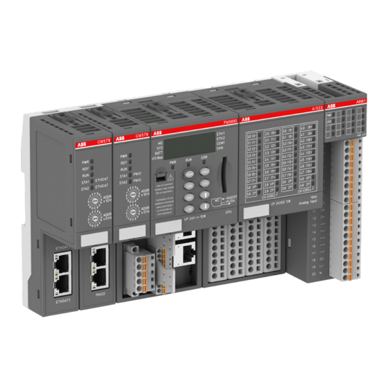
Device specifications Processor modules > AC500 (standard) 1.3.2 AC500 (standard) 1.3.2.1 PM56xx-2ETH for AC500 V3 products Processor modules with onboard interfaces: ● PM5630-2ETH: processor module, memory 8 MB, with Ethernet support (onboard Ethernet) – 2 network interfaces RJ45, CAN and COM1 on the terminal base. - Page 91 Device specifications Processor modules > AC500 (standard) 14 Interface for CAN (5-pin terminal block, removable) 17 RJ45 female connector for ETHERNET1 connection 15 Power supply (5-pin terminal block, removable) 18 RJ45 female connector for ETHERNET2 connection 16 Serial interface COM1 (9-pin terminal block, remov- 19 DIN rail able) Sign for XC version...
- Page 92 All terminals for connection are available on the terminal base. For information on connection and available interfaces see the descriptions for Ä Chapter 1.2.1 “TB56xx for AC500 V3 products” on page 4. ● Processor modules PM56xx-2ETH can only be used with TB56xx-2ETH ter- minal bases.
- Page 93 Device specifications Processor modules > AC500 (standard) Processor module PM5630 PM5650 PM5670 PM5675 TB5660-2ETH 6 slots 6 slots Remarks: The slots can be used for connecting communication modules or AC500-S modules. Note that only one AC500-S module can be connected at one terminal base. ) PM567x must have an index ≥...
- Page 94 Device specifications Processor modules > AC500 (standard) 1.3.2.1.4 LEDs, display and function keys on the front panel Detailed information on using the LEDs, display and the function keys such as startup procedure and error coding is described in the system technology section .
- Page 95 Device specifications Processor modules > AC500 (standard) Parameter Value Max. typ. (all communication modules PM5630-2ETH: 850 mA and I/Os) PM5650-2ETH: 900 mA PM5670-2ETH: 950 mA PM5675-2ETH: 950 mA Number of slots for processor modules 1 (on all terminal bases) Processor module interfaces at the ter- I/O bus, ETH1, ETH2, CAN, COM1 minal bases TB56xx Ä...
- Page 96 Device specifications Processor modules > AC500 (standard) Processor module PM5630 PM565 PM567 PM5675 Motion capability No. synchronized axis per 1 ms on EtherCAT CM typically No. synchronized axis per 2 >32 >32 ms on EtherCAT CM typically No. synchronized axis per >32 >32 >32...
- Page 97 Device specifications Processor modules > AC500 (standard) Processor module PM5630 PM565 PM567 PM5675 Usage CANopen master communication, CAN 2A/2B, J1939 protocol, CAN sync Max. number of variables allowed Input variables 2 kB 4 kB 5 kB 5 kB Output variables 2 kB 4 kB 5 kB...
- Page 98 Device specifications Processor modules > AC500 (standard) Table 44: Comparison: TB56xx Processor module PM5630 PM5650 PM5670 PM5675 Max. number of variables allowed for each communication module supported Input variables 4 kB 4 kB 5 kB 5 kB Output variables 4 kB 4 kB 5 kB 5 kB...
- Page 99 Device specifications Processor modules > AC500 (standard) Table 46: Modbus, Telecontrol Processor module PM5630 PM5650 PM5670 PM5675 Modbus TCP client / server Number of Modbus clients ModMast in parallel on a CPU master (server) Number of Modbus server in parallel (e.g.
- Page 100 Device specifications Processor modules > AC500 (standard) Part no. Description Product life cycle phase *) 1SAP 151 000 R0278 PM5670-2ETH, processor module, Active memory 160 MB, 24 V DC, memory card slot, interface 1 RS-232/485, display, 2 RJ45 independent onboard Ethernet TCP/IP interfaces with Modbus TCP, web server, IEC60870-5-104 or selectable Ethernet based protocols...
-
Page 101: Communication Modules (Ac500 Standard)
Device specifications Communication modules (AC500 standard) > Overview 1.4 Communication modules (AC500 standard) 1.4.1 Overview AC500 communication modules are required for ● a connection to standard field bus systems and ● for integration into existing networks. AC500 communication modules ● enable communication on different field buses. - Page 102 6 communication modules can be connected. ● Ä Chapter 1.2.1 “TB56xx for AC500 V3 products” on page 4 There are no restrictions concerning which communication modules can be arranged for a processor module.
- Page 103 Device specifications Communication modules (AC500 standard) > Overview 1.4.1.1 Compatibility of communication modules and communication interface modules Table 48: Modbus TCP Communication Communication I/O expansion I/O expansion I/O expansion Applications module interface module module module module S500 S500-eCo S500-S Onboard CI521-MODTCP high availability, Ethernet inter-...
-
Page 104: Compatibility Of Communication Modules And Communication Interface Modules
Device specifications Communication modules (AC500 standard) > Compatibility of communication modules and communication interface modules 1.4.1.2 Technical data (Overview) Com- Field Trans- Field Pro- Com- Cur- Interna External External muni- mis- cessor muni- rent l RAM flash cation sion con- cation con- memor... -
Page 105: Canopen
Device specifications Communication modules (AC500 standard) > CANopen Table 54: CANopen Communication Communication I/O expansion I/O expansion I/O expansion Applications module interface module module module module S500 S500-eCo S500-S Onboard CAN CI581-CN remote I/O interface CI582-CN Table 55: EtherCAT Communication Communication I/O expansion I/O expansion... - Page 106 For use in extreme ambient conditions (e.g. wider temperature and humidity range), a special XC version of the device is available. The AC500 V3 CPUs only support CAN 2A/2B protocol on the communication module CM598-CAN. Support of CANopen protocol is in preparation.
- Page 107 Device specifications Communication modules (AC500 standard) > CANopen 1.4.3.1.2 Connections Field bus interface Interface socket 5-pin COMBICON Transmission standard ISO 11898, potential-free Transmission protocol CANopen (CAN), 1 Mbaud max. Transfer rate (transmis- 10 kbit/s, 20 kbit/s, 50 kbit/s, 100 kbit/s, 125 kbit/s, 250 kbit/s, 500 sion rate) kbit/s, 800 kbit/s and 1 Mbit/s, The CANopen connector has the following pin assignment:...
- Page 108 Device specifications Communication modules (AC500 standard) > CANopen Length of seg- Bus cable (shielded, twisted pair) Max. transmis- ment [m] sion rate [kbit/s] Conductor Line resistance Wave impe- cross section [W/km] dance [W] [mm²] 0...40 0.25...0.34 / 1000 at 40 m AWG23, AWG22 40...300 0.34...0.60 /...
- Page 109 Device specifications Communication modules (AC500 standard) > CANopen +24 V Fig. 5: DeviceNet interface, bus terminating resistors connected to the line ends DeviceNet power supply COMBICON connection, DeviceNet interface Data lines, twisted pair cables black white blue bare The grounding of the shield should take place at the switchgear. Please refer to Ä...
- Page 110 Device specifications Communication modules (AC500 standard) > CANopen 1.4.3.1.3 State LEDs Table 56: Meaning of the diagnosis LEDs Color State Description Green ON (light) Power supply available OFF (dark) Power supply not available or defective hardware Yellow ON Boot procedure Blinking Boot failure Green...
- Page 111 Device specifications Communication modules (AC500 standard) > CANopen Parameter Value Protocol CANopen master (in preparation), CAN2A, CAN2B Transmission rate 10 kbit/s to 1 Mbit/s Ambient temperature see: Ä Chapter 2.6.1 “System System data AC500 data AC500” on page 971 System Data AC500 XC Ä...
-
Page 112: Ethercat
Device specifications Communication modules (AC500 standard) > EtherCAT 1.4.4 EtherCAT 1.4.4.1 CM579-ETHCAT - EtherCAT master 5 LEDs for state display 2 rotary switches for address setting (not used) Label 2 communication interfaces RJ45 (ETHCAT1 and ETHCAT2) 1.4.4.1.1 Intended purpose Communication module CM579-ETHCAT is for EtherCAT communication. The comunication module is configured via the dual-port memory by means of a system config- urator. - Page 113 Device specifications Communication modules (AC500 standard) > EtherCAT Pin assignment Interface Signal Description TxD+ Transmit data + TxD- Transmit data - RxD+ Receive data + Not connected Not connected RxD- Receive data - Not connected Not connected Shield Cable shield Functional earth In corrosive environment, please protect unused connectors using the TA535 accessory.
- Page 114 Device specifications Communication modules (AC500 standard) > EtherCAT 1.4.4.1.3 State LEDs The EtherCAT state is shown by the EtherCAT communication module's LEDs. Some LEDs are two-colored. Table 57: Meaning of the diagnosis LEDs Color State Description Green Power supply available Blinking Power supply not available or defective hardware...
- Page 115 PM56xx AC500 V3 products” on page 90 Usable terminal bases All TB56xx (not TB5600) Ä Chapter 1.2.1 “TB56xx for AC500 V3 products” on page 4 Ambient temperature System data AC500 Ä Chapter 2.6.1 “System data AC500” on page 971 Ä Chapter 2.7.1 System Data AC500 XC “System data AC500-XC”...
-
Page 116: Profinet
Device specifications Communication modules (AC500 standard) > PROFINET 1.4.4.1.5 Ordering data Part no. Description Product life cycle phase *) 1SAP 170 902 R0101 CM579-ETHCAT, EtherCAT Active communication module *) Modules in lifecycle Classic are available from stock but not recommended for planning and commissioning of new installations. - Page 117 Ä Chapter 1.3.2.1 “PM56xx-2ETH for AC500 V3 products” on page 90 Usable terminal bases All TB56xx (not TB5600) Ä Chapter 1.2.1 “TB56xx for AC500 V3 products” on page 4 Field bus connector 2 RJ45 (PNIO1 and PNIO2), with integrated 2-port switch Internal supply...
- Page 118 Device specifications Communication modules (AC500 standard) > PROFINET For further information regarding wiring and cable types see chapter Ethernet Ä Chapter 2.6.4.7 “Ethernet connection details” on page 997. 3ADR010278, 3, en_US 2022/01/31...
- Page 119 Device specifications Communication modules (AC500 standard) > PROFINET 1.4.5.1.4 State LEDs The PROFINET state is shown by the state LEDs. Table 59: Meaning of the diagnosis LEDs Color State Description Green Power supply available Blinking Power supply not available or defective hardware Yellow On Boot procedure...
- Page 120 5 LEDs Usable terminal bases All TB5xx Ä Chapter 1.2.1 All TB56xx (not TB5600) “TB56xx for AC500 V3 products” on page 4 Supported alarm types Process alarm, diagnostic alarm, return of Sub- Module, plug alarm, pull alarm Alarm processing Requires handling in application program Current consumption from 24 V DC power Typ.
- Page 121 Device specifications Communication modules (AC500 standard) > PROFINET Parameter Value Supported protocols RTC - real-time cyclic protocol, class 1 RTA - real-time acyclic protocol DCP - discovery and configuration protocol *) CL-RPC - connectionless remote procedure call Since revision FW 2.4.8.0 additionally LLDP - link layer discovery protocol SNMP - simply network management protocol (SNMP v1)
-
Page 122: Terminal Units (Ac500 Standard)
Device specifications Terminal units (AC500 standard) > TU507-ETH and TU508-ETH for Ethernet communication interface modules 1.5 Terminal units (AC500 standard) Hot swap System requirements for hot swapping of I/O modules: – Types of terminal units that support hot swapping of I/O modules have the appendix TU5xx-H. - Page 123 Device specifications Terminal units (AC500 standard) > TU507-ETH and TU508-ETH for Ethernet communication interface modules I/O bus (10 pins, female) to connect the first terminal unit 2a Plug (2x 25 pins) to connect the inserted Ethernet communication interface module 2b Plug (3x 19 pins) to connect the inserted Ethernet communication interface module With a screwdriver, inserted in this place, the terminal unit and the adjacent terminal unit can be shoved from each other 2 holes for wall mounting...
- Page 124 Device specifications Terminal units (AC500 standard) > TU507-ETH and TU508-ETH for Ethernet communication interface modules XC version XC = eXtreme Conditions Extreme conditions Terminal units for use in extreme ambient conditions have no sign for XC version. The figure 4 in the Part no. 1SAP4... (label) identifies the XC version. Terminals Screw terminals Spring terminals...
- Page 125 Device specifications Terminal units (AC500 standard) > TU507-ETH and TU508-ETH for Ethernet communication interface modules NOTICE! Risk of corrosion! Unused connectors and slots may corrode if XC devices are used in salt-mist environments. Protect unused connectors and slots with TA535 protective caps for XC Ä...
-
Page 126: Tu515, Tu516, Tu541 And Tu542 For I/O Modules
Device specifications Terminal units (AC500 standard) > TU515, TU516, TU541 and TU542 for I/O modules 1.5.1.2 Ordering data Part no. Description Product life cycle phase *) 1SAP 214 200 R0001 TU507-ETH, Ethernet terminal unit, Active 24 V DC, screw terminals 1SAP 214 000 R0001 TU508-ETH, Ethernet terminal unit, Active 24 V DC, spring terminals... - Page 127 Device specifications Terminal units (AC500 standard) > TU515, TU516, TU541 and TU542 for I/O modules I/O bus (10 pins, male) to connect the previous terminal unit, the CPU terminal base or the communication interface module to the terminal unit I/O bus (10 pins, female) to connect other terminal units 3a Plug (2 x 25 pins) to connect the inserted I/O modules 3b Plug (2 x 19 pins) to connect the inserted I/O modules With a screwdriver inserted in this place, the terminal unit and the adjacent terminal unit can...
- Page 128 Device specifications Terminal units (AC500 standard) > TU515, TU516, TU541 and TU542 for I/O modules WARNING! Electric shock due to negligent behavior during hot swapping! To avoid electric shock – make sure the following conditions apply: – Digital outputs are not under load. –...
- Page 129 Device specifications Terminal units (AC500 standard) > TU515, TU516, TU541 and TU542 for I/O modules The index of the module is in the right corner of the label. NOTICE! Risk of damage to I/O modules! Modules with index below F0 can be damaged when inserted or removed from the terminal unit in a powered system.
- Page 130 Device specifications Terminal units (AC500 standard) > TU515, TU516, TU541 and TU542 for I/O modules Device Min. required device index for I/O module as of FW Version 3.0.14 DI572 DO524 (-XC) DO526 DO526-XC DO561 DO562 DO571 DO572 DO573 DX522 (-XC) DX531 DX561 DX571...
- Page 131 Device specifications Terminal units (AC500 standard) > TU515, TU516, TU541 and TU542 for I/O modules – For information about wiring specifications see the description of the ter- Ä Chapter 2.6.4.3 “Terminals at the terminal unit” on page 990. minal units –...
-
Page 132: Tu517 And Tu518 For Communication Interface Modules
Device specifications Terminal units (AC500 standard) > TU517 and TU518 for communication interface modules Parameter Value Screw terminals Front terminal, conductor connection vertically with respect to the printed circuit board Spring terminals Front terminal, conductor connection vertically with respect to the printed circuit board Weight 200 g Mounting position... - Page 133 Device specifications Terminal units (AC500 standard) > TU517 and TU518 for communication interface modules I/O bus (10 pins, female) to connect the first terminal unit 2a Plug (2 25 pins) to connect the inserted communication interface module 2b Plug (2 19 pins) to connect the inserted communication interface module With a screwdriver, inserted in this place, the terminal unit and the adjacent I/O terminal unit can be shoved from each other 2 holes for wall mounting...
- Page 134 Device specifications Terminal units (AC500 standard) > TU517 and TU518 for communication interface modules XC version XC = eXtreme Conditions Extreme conditions Terminal units for use in extreme ambient conditions have no sign for XC version. The figure 4 in the Part no. 1SAP4... (label) identifies the XC version. Terminals Screw terminals Spring terminals...
-
Page 135: Tu531 And Tu532 For I/O Modules
Device specifications Terminal units (AC500 standard) > TU531 and TU532 for I/O modules Ä Chapter 2.7.1 “System data AC500-XC” on page 1023 are The system data of AC500-XC applicable to the XC version. Only additional details are therefore documented below. The technical data are also applicable to the XC version. - Page 136 Device specifications Terminal units (AC500 standard) > TU531 and TU532 for I/O modules I/O bus (10 pins, male) to connect the previous terminal unit, the CPU terminal base or the communication interface module to the terminal unit I/O bus (10 pins, female) to connect other terminal units 3a Plug (2 x 25 pins) to connect the inserted I/O modules 3b Plug (3 x 19 pins) to connect the inserted I/O modules With a screwdriver inserted in this place, the terminal unit and the adjacent I/O terminal unit...
- Page 137 Device specifications Terminal units (AC500 standard) > TU531 and TU532 for I/O modules WARNING! Electric shock due to negligent behavior during hot swapping! To avoid electric shock – make sure the following conditions apply: – Digital outputs are not under load. –...
- Page 138 Device specifications Terminal units (AC500 standard) > TU531 and TU532 for I/O modules The index of the module is in the right corner of the label. NOTICE! Risk of damage to I/O modules! Modules with index below F0 can be damaged when inserted or removed from the terminal unit in a powered system.
- Page 139 Device specifications Terminal units (AC500 standard) > TU531 and TU532 for I/O modules Device Min. required device index for I/O module as of FW Version 3.0.14 DI572 DO524 (-XC) DO526 DO526-XC DO561 DO562 DO571 DO572 DO573 DX522 (-XC) DX531 DX561 DX571 FM562 XC version...
- Page 140 Device specifications Terminal units (AC500 standard) > TU531 and TU532 for I/O modules – For information about wiring specifications see the description of the ter- Ä Chapter 2.6.4.3 “Terminals at the terminal unit” on page 990. minal units – For a detailed description of the mounting, disassembly and connection of the module, please refer to the System Assembly, Construction and Con- nection chapter Ä...
- Page 141 Device specifications Terminal units (AC500 standard) > TU531 and TU532 for I/O modules Parameter Value Number of channels per module Distribution of the channels into groups 4 groups of 8 channels each (1.0...1.7, 2.0...2.7, 3.0...3.7, 4.0...4.7), the allocation of the channels is given by the inserted I/O module Terminals 1.8...4.8 and 1.9...4.9 Max.
-
Page 142: I/O Modules
Device specifications I/O modules > Digital I/O modules 1.6 I/O modules Hot swap System requirements for hot swapping of I/O modules: – Types of terminal units that support hot swapping of I/O modules have the appendix TU5xx-H. – I/O modules as of index F0. The following I/O bus masters support hot swapping of attached I/O modules: –... - Page 143 Device specifications I/O modules > Digital I/O modules I/O bus 16 yellow LEDs to display the states of the inputs/outputs C0 to C15 Terminal number Allocation of signal name Interfast connector (20-pin) 2 holes for wall-mounting with screws DIN rail Intended purpose The digital I/O module DC561 can be connected to the following devices via the I/O bus connector:...
- Page 144 Device specifications I/O modules > Digital I/O modules The inputs/outputs are group-wise galvanically isolated from each other. All other circuitry of the module is galvanically isolated from the inputs/outputs. Functionality Parameter Value Digital inputs Max. 16 (24 V DC), can be used as sink inputs Digital outputs Max.
- Page 145 Device specifications I/O modules > Digital I/O modules Signal Description Process voltage UP +24 V DC Process voltage ZP 0 V DC The arrow located next to the Interfast connector marks terminal 1. The internal power supply voltage for the module's circuitry is carried out via the I/O bus (provided by a communication interface module or a CPU).
- Page 146 Device specifications I/O modules > Digital I/O modules Ä Chapter 1.6.1.1.1.6 “Diagnosis” The module provides several diagnosis functions on page 147. The meaning of the LEDs is described in the section State LEDs Ä Chapter 1.6.1.1.1.7 “State LEDs” on page 147. I/O Configuration The module itself does not store configuration data.
- Page 147 Device specifications I/O modules > Digital I/O modules Diagnosis E1...E4 Identifier AC500- <− Display in Display 000...063 Class Comp PS501 Browser Byte 6 Byte 3 Byte 4 Byte 5 Byte 6 PNIO diagnosis Bit 6...7 Bit 0...5 block Class Interface Device Module Channel...
- Page 148 Device specifications I/O modules > Digital I/O modules Technical data Ä Chapter 2.5.1 “System data AC500-eCo V3” The System Data of AC500-eCo apply on page 925 Only additional details are therefore documented below. Parameter Value Process voltage UP Connections Terminals 17 and 19 for UP (+24 V DC); termi- nals 18 and 20 for ZP (0 V) Rated value 24 V DC...
- Page 149 Device specifications I/O modules > Digital I/O modules Parameter Value Indication of the input signals 1 yellow LED per channel; the LED is ON when the input signal is high (signal 1). The module is powered via the I/O bus. Input type according to EN 61131-2 Type 1 sink Input signal range...
- Page 150 Device specifications I/O modules > Digital I/O modules Parameter Value Rated current (all channels together, 1.6 A max.) Lamp load (max.) Not applicable Max. leakage current with signal 0 < 0.5 mA Output type Non-protected Protection type External fuse on each channel Rated protection fuse (for each channel) 1 A fast Demagnetization when inductive loads are...
- Page 151 Device specifications I/O modules > Digital I/O modules I/O bus 16 yellow LEDs to display the states of the inputs/outputs C0 to C15 Terminal number Allocation of signal name Terminal block for input and output signals (9-pin) Terminal block for input and output signals (11-pin) 2 holes for wall-mounting with screws DIN rail Intended purpose...
- Page 152 Device specifications I/O modules > Digital I/O modules Functionality Parameter Value LED displays For signal states Internal power supply Via I/O bus External power supply Via the terminals ZP and UP (process voltage 24 V Connections For a detailed description of the mounting, disassembly and connection of the Ä...
- Page 153 Device specifications I/O modules > Digital I/O modules C10 13 C11 14 C12 15 C13 16 C14 17 C15 18 UP 19 Table 62: Assignment of the terminals: Terminal Signal Description Reserved Input/output signal C0 Input/output signal C1 Input/output signal C2 Input/output signal C3 Input/output signal C4 Input/output signal C5...
- Page 154 Device specifications I/O modules > Digital I/O modules Terminal Signal Description Input/output signal C6 Input/output signal C7 Reserved Input/output signal C8 Input/output signal C9 Input/output signal C10 Input/output signal C11 Input/output signal C12 Input/output signal C13 Input/output signal C14 Input/output signal C15 Process voltage UP +24 V DC Process voltage ZP 0 V DC The internal power supply voltage for the module's circuitry is carried out via the I/O bus...
- Page 155 Device specifications I/O modules > Digital I/O modules Process supply voltage must be connected to UP/ZP of the module. The inputs and UP/ZP must use the same power supply. The following figure shows the connection of the digital input/output module DC562: 3 C1 4 C2 5 C3...
- Page 156 Device specifications I/O modules > Digital I/O modules I/O configuration The module itself does not store configuration data. It receives its parameterization data from the master device of the I/O bus (CPU or communication interface module) during power-up of the system. Hence, replacing I/O modules is possible without any re-parameterization via software.
- Page 157 Device specifications I/O modules > Digital I/O modules Diagnosis E1...E4 Identifier AC500- <− Display in Display 000...063 Class Comp PS501 Browser Byte 6 Byte 3 Byte 4 Byte 5 Byte 6 PNIO diagnosis Bit 6...7 Bit 0...5 block Class Inter- Device Module Channel...
- Page 158 Device specifications I/O modules > Digital I/O modules Technical data Ä Chapter 2.5.1 “System data AC500-eCo V3” The System Data of AC500-eCo apply on page 925 Only additional details are therefore documented below. Parameter Value Process voltage UP Connections Terminal 19 for UP (+24 V DC) and terminal 20 for ZP (0 V) Rated value 24 V DC...
- Page 159 Device specifications I/O modules > Digital I/O modules Parameter Value Input signal range +24 V DC Signal 0 -3 V...+5 V Undefined signal +5 V...+15 V Signal 1 +15 V...+30 V Ripple with signal 0 -3 V...+5 V Ripple with signal 1 +15 V...+30 V Input current per channel Input voltage +24 V...
- Page 160 Device specifications I/O modules > Digital I/O modules Parameter Value Max. leakage current with signal 0 < 0.5 mA Output type Non-protected Protection type External fuse on each channel Rated protection fuse (for each channel) 3 A fast Demagnetization when inductive loads are Must be performed externally according to switched off driven load specification...
- Page 161 Device specifications I/O modules > Digital I/O modules 1.6.1.1.3 DI561 - Digital input module ● 8 digital inputs 24 V DC / 24 V AC (I0 to I7) in 1 group ● Module-wise galvanically isolated I/O bus 8 yellow LEDs to display the signal states of the inputs I0 to I7 Terminal number Allocation of signal name Terminal block for input signals (9-pin)
- Page 162 Device specifications I/O modules > Digital I/O modules The I/O module must not be used as a decentralized I/O module with CI590- CS31-HA communication interface modules. Functionality Parameter Value LED displays For signal states Internal power supply Via I/O bus External power supply Not necessary Connections...
- Page 163 Device specifications I/O modules > Digital I/O modules Terminal Signal Description Input signal I2 Input signal I3 Input signal I4 Input signal I5 Input signal I6 Input signal I7 The internal power supply voltage for the module's circuitry is carried out via the I/O bus (provided by a communication interface module or a CPU).
- Page 164 Device specifications I/O modules > Digital I/O modules C0..7 C0..7 3 I1 3 I1 4 I2 4 I2 + / ~ + / ~ 5 I3 5 I3 24 V 24 V DC/AC DC/AC – / ~ – / ~ 7 I5 7 I5 8 I6...
- Page 165 Device specifications I/O modules > Digital I/O modules ) the module has no additional user-configurable parameters ) Value is hexadecimal: HighByte is slot (xx: 0...7), LowByte is index (1...n) GSD file: Ext_User_Prm_Data_Len = 0x03 Ext_User_Prm_Data_Const(0) = 0xDA, 0x17, 0x00; Diagnosis E1...E4 Identifier AC500-...
- Page 166 Device specifications I/O modules > Digital I/O modules State LEDs State Color LED = OFF LED = ON Inputs I0...I7 Digital input Yellow Input is OFF Input is ON In the undefined signal range, the state LED for the inputs can be ON although the input state detected by the module is OFF.
- Page 167 Device specifications I/O modules > Digital I/O modules Parameter Value Input signal range -24 V DC +24 V DC 24 V AC 50/60 Hz Signal 0 -5 V...+3 V -3 V...+5 V 0 V AC...5 V AC Undefined signal -15 V...-5 V +5 V...+15 V 5 V AC...14 V AC Signal 1...
- Page 168 Device specifications I/O modules > Digital I/O modules I/O bus 16 yellow LEDs to display the signal states of the inputs I0 to I15 Terminal number Allocation of signal name Terminal block for input signals (9-pin) Terminal block for input signals (11-pin) 2 holes for wall-mounting with screws DIN rail Intended purpose...
- Page 169 Device specifications I/O modules > Digital I/O modules Functionality Parameter Value LED displays For signal states Internal power supply Via I/O bus External power supply Not necessary Connections For a detailed description of the mounting, disassembly and connection of the module, please refer to the System Assembly chapter Ä...
- Page 170 Device specifications I/O modules > Digital I/O modules Terminal Signal Description C0...7 Input common for signals I0 to I7 Input signal I0 Input signal I1 Input signal I2 Input signal I3 Input signal I4 Input signal I5 Input signal I6 Input signal I7 C8...15 Input common for signals I8 to I15...
- Page 171 Device specifications I/O modules > Digital I/O modules NOTICE! Risk of damaging the PLC modules! Overvoltages and short circuits might damage the PLC modules. – Make sure that all voltage sources (supply voltage and process supply voltage) are switched off before you begin with operations on the system. –...
- Page 172 Device specifications I/O modules > Digital I/O modules Ä Chapter 1.6.1.1.4.7 “State The meaning of the LEDs is described in section State LEDs LEDs” on page 173. I/O configuration The module itself does not store configuration data. It receives its parameterization data from the master device of the I/O bus (CPU or communication interface module) during power-up of the system.
- Page 173 Device specifications I/O modules > Digital I/O modules Diagnosis E1...E4 Identifier AC500- <− Display in Display 000...063 Class Comp PS501 Browser Byte 6 Byte 3 Byte 4 Byte 5 Byte 6 PNIO diagnosis Bit 6...7 Bit 0...5 block Class Interface Device Module Channel...
- Page 174 Device specifications I/O modules > Digital I/O modules In the undefined signal range, the state LED for the inputs can be ON although the input state detected by the module is OFF. Technical data Ä Chapter 2.5.1 “System data AC500-eCo V3” The System Data of AC500-eCo apply on page 925 Only additional details are therefore documented below.
- Page 175 Device specifications I/O modules > Digital I/O modules Parameter Value Signal 1 -30 V...-15 V +15 V...+30 V 14 V AC...27 V Input current per channel Input voltage 24 V Typ. 5 mA Typ. 5 mA r.m.s. Input voltage 5 V Typ.
- Page 176 Device specifications I/O modules > Digital I/O modules 1.6.1.1.5 DI571 - Digital input module ● 8 digital inputs 100-240 V AC (I0 to I7) in 8 groups ● Module-wise galvanically isolated I/O bus 8 yellow LEDs to display the signal states of the inputs I0 to I7 Terminal number Allocation of signal name Terminal block for input signals (9-pin)
- Page 177 Device specifications I/O modules > Digital I/O modules The I/O module must not be used as a decentralized I/O module with CI590- CS31-HA communication interface modules. Functionality Parameter Value LED displays For signal states Internal power supply Via I/O bus External power supply Not necessary Connections...
- Page 178 Device specifications I/O modules > Digital I/O modules −−− −−− −−− −−− Table 64: Assignment of the terminals: Terminal Signal Description Input signal I0 Neutral conductor for the input signal I0 Input signal I1 Neutral conductor for the input signal I1 Input signal I2 Neutral conductor for the input signal I2 Input signal I3...
- Page 179 Device specifications I/O modules > Digital I/O modules Terminal Signal Description Neutral conductor for the input signal I6 Input signal I7 Neutral conductor for the input signal I7 Reserved Reserved Reserved The internal power supply voltage for the module's circuitry is carried out via the I/O bus (provided by a communication interface module or a CPU).
- Page 180 Device specifications I/O modules > Digital I/O modules 3 I1 4 N1 5 I2 6 N2 7 I3 8 N3 9 −−− 12 I5 13 N5 14 I6 15 N6 16 I7 17 N7 18 −−− 19 −−− 20 −−− NOTICE! Risk of damaging the PLC modules! The PLC modules will be irreparably damaged if a voltage >...
- Page 181 Device specifications I/O modules > Digital I/O modules Internal data exchange Parameter Value Digital inputs (bytes) Digital outputs (bytes) I/O configuration The module itself does not store configuration data. It receives its parameterization data from the master device of the I/O bus (CPU or communication interface module) during power-up of the system.
- Page 182 Device specifications I/O modules > Digital I/O modules Diagnosis E1...E4 Identifier AC500- <− Display in Display 000...063 Class Comp PS501 Browser Byte 6 Byte 3 Byte 4 Byte 5 Byte 6 PNIO diagnosis Bit 6...7 Bit 0...5 block Class Interface Device Module Channel...
- Page 183 Device specifications I/O modules > Digital I/O modules Technical data Ä Chapter 2.5.1 “System data AC500-eCo V3” The System Data of AC500-eCo apply on page 925 Only additional details are therefore documented below. Parameter Value Galvanic isolation Yes, between the channels and the rest of the module Isolated groups 8 (1 channel per group)
- Page 184 Device specifications I/O modules > Digital I/O modules Parameter Value Shielded 500 m Unshielded 300 m Ordering data Part no. Description Product life cycle phase *) 1TNE 968 902 R2103 DI571, digital input module, 8 DI, Active 100 V AC...240 V AC 1TNE 968 901 R3101 Terminal block TA563-9, 9 pins, screw Active front, cable side, 6 pieces per unit...
- Page 185 Device specifications I/O modules > Digital I/O modules I/O bus 16 yellow LEDs to display the signal states of the inputs I0 to I15 Terminal number Allocation of signal name Terminal block for input signals (9-pin) Terminal block for input signals (11-pin) 2 holes for wall-mounting with screws DIN rail Intended purpose...
- Page 186 Device specifications I/O modules > Digital I/O modules Functionality Parameter Value LED displays For signal states Internal power supply Via I/O bus External power supply Not necessary Connections For a detailed description of the mounting, disassembly and connection of the module, please refer to the System Assembly chapter Ä...
- Page 187 Device specifications I/O modules > Digital I/O modules Table 65: Assignment of the terminals Terminal Signal Description Input signal I0 Input signal I1 Input signal I2 Input signal I3 Input signal I4 Input signal I5 Input signal I6 Input signal I7 N0...7 Neutral conductor for the input signals I0...I7 Input signal I8...
- Page 188 Device specifications I/O modules > Digital I/O modules WARNING! Removal/Insertion under power The devices are not designed for removal or insertion under power. Because of unforeseeable consequences, it is not allowed to plug or unplug devices with the power being ON. Make sure that all voltage sources (supply and process voltage) are switched off before you –...
- Page 189 Device specifications I/O modules > Digital I/O modules 3 I2 4 I3 5 I4 6 I5 7 I6 8 I7 9 N0..7 12 I10 13 I11 14 I12 15 I13 16 I14 17 I15 18 N8..15 19 --- 20 --- NOTICE! Risk of damaging the PLC modules! The PLC modules will be irreparably damaged if a voltage >...
- Page 190 Device specifications I/O modules > Digital I/O modules Hence, replacing I/O modules is possible without any re-parameterization via software. If the external power supply voltage via UP/ZP terminals fails, the I/O module loses its configuration data. The whole station has to be switched off and on again to re-configure the module.
- Page 191 Device specifications I/O modules > Digital I/O modules Diagnosis E1...E4 Identifier AC500- <− Display in Display 000...063 Class Comp PS501 Browser Byte 6 Byte 3 Byte 4 Byte 5 Byte 6 PNIO diagnosis Bit 6...7 Bit 0...5 block Class Interface Device Module Channel...
- Page 192 Device specifications I/O modules > Digital I/O modules Technical data Ä Chapter 2.5.1 “System data AC500-eCo V3” The System Data of AC500-eCo apply on page 925 Only additional details are therefore documented below. Parameter Value Galvanic isolation Yes, between the input groups and the rest of the module Isolated groups 2 (8 channels per group)
- Page 193 Device specifications I/O modules > Digital I/O modules Parameter Value Max. permissible leakage current (at 2-wire prox- 1 mA imity switches) Max. cable length Shielded 1000 m Unshielded 600 m Ordering data Part no. Description Product life cycle phase *) 1SAP 230 500 R0000 DI572, digital input module, 16 DI, Active 100 V AC...240 V AC...
- Page 194 Device specifications I/O modules > Digital I/O modules I/O bus 8 yellow LEDs to display the signal states of the outputs O0 to O7 Terminal number Allocation of signal name Terminal block for output signals (11-pin) 2 holes for wall-mounting with screws DIN rail Intended purpose The device can be used as a decentralized I/O extension module for S500 communication...
- Page 195 Device specifications I/O modules > Digital I/O modules Functionality Parameter Value LED displays For signal states Internal power supply Via I/O bus External power supply Via the terminals ZP and UP (process supply voltage 24 V DC) Connections For a detailed description of the mounting, disassembly and connection of the Ä...
- Page 196 Device specifications I/O modules > Digital I/O modules Terminals Signal Description Output signal O5 Output signal O6 Output signal O7 Process supply voltage UP +24 V DC Process supply voltage ZP 0 V The internal power supply voltage for the module's circuitry is carried out via the I/O bus (provided by a communication interface module or a CPU).
- Page 197 Device specifications I/O modules > Digital I/O modules −−− 12 O1 13 O2 14 O3 15 O4 16 O5 17 O6 18 O7 19 UP 24 VDC − 20 ZP NOTICE! Risk of malfunctions in the plant! The outputs may switch on for a period of 10 to 50 µs if the process supply voltage UP/ZP is switched on.
- Page 198 Device specifications I/O modules > Digital I/O modules If the external power supply voltage via UP/ZP terminals fails, the I/O module loses its configuration data. The whole station has to be switched off and on again to re-configure the module. Parameterization The arrangement of the parameter data is performed with Automation Builder software.
- Page 199 Device specifications I/O modules > Digital I/O modules E1...E4 Identifier AC500- <− Display in Display 000...063 Class Comp PS501 Browser Byte 6 Byte 3 Byte 4 Byte 5 Byte 6 PNIO diagnosis Bit 6...7 Bit 0...5 block Class Interface Device Module Channel Error...
- Page 200 Device specifications I/O modules > Digital I/O modules Technical data Ä Chapter 2.5.1 “System data AC500-eCo V3” The System Data of AC500-eCo apply on page 925 Only additional details are therefore documented below. Parameter Value Process supply voltage UP Connections Terminal 19 for UP (+24 V DC) and terminal 20 for ZP (0 V DC) Rated value...
- Page 201 Device specifications I/O modules > Digital I/O modules Parameter Value Way of operation Non-latching type Min. output voltage at signal 1 20 V DC at max. current consumption Output delay (max. at rated load) 0 to 1 50 µs 1 to 0 200 µs Output data length 1 byte...
- Page 202 Device specifications I/O modules > Digital I/O modules *) Modules in lifecycle Classic are available from stock but not recommended for planning and commissioning of new installations. 1.6.1.1.8 DO562 - Digital output module ● 16 digital outputs 24 V DC (O0 to O15) in 1 group ●...
- Page 203 Device specifications I/O modules > Digital I/O modules Intended purpose The device can be used as a decentralized I/O extension module for S500 communication iInterface modules (e. g. CI592-CS31, CI501-PNIO, CI541-DP, CI581-CN) or as a centralized extension module for AC500 CPUs. The outputs are group-wise galvanically isolated from each other.
- Page 204 Device specifications I/O modules > Digital I/O modules O10 13 O11 14 O12 15 O13 16 O14 17 O15 18 Table 67: Assignment of the terminals: Terminal Signal Description Reserved Output signal O0 Output signal O1 Output signal O2 Output signal O3 Output signal O4 Output signal O5 Output signal O6...
- Page 205 Device specifications I/O modules > Digital I/O modules Terminal Signal Description Output signal O12 Output signal O13 Output signal O14 Output signal O15 Process voltage UP (24 V DC) Process voltage ZP (0 V DC) The internal power supply voltage for the module's circuitry is carried out via the I/O bus (provided by a communication interface module or a CPU).
- Page 206 Device specifications I/O modules > Digital I/O modules 3 O1 4 O2 5 O3 6 O4 7 O5 8 O6 9 O7 12 O9 13 O10 14 O11 15 O12 16 O13 17 O14 18 O15 19 UP 24 VDC 20 ZP NOTICE! Risk of malfunctions in the plant!
- Page 207 Device specifications I/O modules > Digital I/O modules NOTICE! Risk of damaging the I/O module! The outputs are not protected against short circuits and overload. – Never short-circuit or overload the outputs. – Never connect the outputs to other voltages. –...
- Page 208 Device specifications I/O modules > Digital I/O modules Diagnosis E1...E4 Identifier AC500- <− Display in 000...063 Display Class Comp PS501 Browser Byte 6 Byte 3 Byte 4 Byte 5 Byte 6 PNIO diagnosis Bit 6...7 Bit 0...5 block Class Inter- face Device Module Channel Error-...
- Page 209 Device specifications I/O modules > Digital I/O modules Technical data Ä Chapter 2.5.1 “System data AC500-eCo V3” The System Data of AC500-eCo apply on page 925 Only additional details are therefore documented below. Parameter Value Process supply voltage UP Connections Terminal 19 for UP (+24 V DC) and terminal 20 for ZP (0 V DC) Rated value...
- Page 210 Device specifications I/O modules > Digital I/O modules Parameter Value Indication of the output signals 1 yellow LED per channel; the LED is on when the output signal is high (signal 1) and the module is powered via the I/O bus Way of operation Non-latching type Min.
- Page 211 Device specifications I/O modules > Digital I/O modules Part no. Description Product life cycle phase *) 1TNE 968 901 R3103 Terminal block TA564-9, 9 pins, screw Active front, cable front, 6 pieces per unit 1TNE 968 901 R3104 Terminal block TA564-11, 11 pins, Active screw front, cable front, 6 pieces per unit...
- Page 212 Device specifications I/O modules > Digital I/O modules I/O bus 8 yellow LEDs to display the signal states of the outputs O0 to O7 Terminal number Allocation of signal name Terminal block for output signals (11-pin) 2 holes for wall-mounting with screws DIN rail Intended purpose The device can be used as a decentralized I/O extension module for S500 communication...
- Page 213 Device specifications I/O modules > Digital I/O modules Functionality Parameter Value LED displays For signal states Internal power supply Via I/O bus External power supply Via the terminal L+ (process voltage 24 V DC). The negative pole is provided by the I/O bus. Connections For a detailed description of the mounting, disassembly and connection of the Ä...
- Page 214 Device specifications I/O modules > Digital I/O modules Terminal Signal Description Normally-open contact of the output NO5 Normally-open contact of the output NO6 Normally-open contact of the output NO7 R4..7 Output common for signals NO4 to NO7 Process voltage L+ +24 V DC The internal power supply voltage for the module's circuitry is carried out via the I/O bus (provided by a communication interface module or a CPU).
- Page 215 Device specifications I/O modules > Digital I/O modules NOTICE! Risk of damaging the PLC modules! Overvoltages and short circuits might damage the PLC modules. – Make sure that all voltage sources (supply voltage and process supply voltage) are switched off before you begin with operations on the system. –...
- Page 216 Device specifications I/O modules > Digital I/O modules 24 VAC/ 120 VAC/ 240 VAC 12 NO2 13 NO3 14 R0...3 15 NO4 24 VAC/ 16 NO5 120 VAC/ 240 VAC 17 NO6 18 NO7 19 R4...7 20 L+ Fig. 8: Connection of 24 V AC or 100-240 V AC actuators NOTICE! Risk of damaging the I/O module! The outputs are not protected against short circuit and overload.
- Page 217 Device specifications I/O modules > Digital I/O modules The L+ connection of the DO571 and the 24 V supply of the CPU/communica- tion interface module must be connected to the same 24 V power supply. The module provides several diagnosis functions (see Diagnosis Ä...
- Page 218 Device specifications I/O modules > Digital I/O modules Ext_User_Prm_Data_Len = 0x04 Ext_User_Prm_Data_Const(0) = 0xEF, 0x17, 0x00,\ 0x01; Diagnosis E1...E4 Identi- AC500- <− Display in fier Display 000...06 Class Comp PS501 Browser Byte 6 Byte 3 Byte 4 Byte 5 Byte 6 PNIO diag- Bit 6...7...
- Page 219 Device specifications I/O modules > Digital I/O modules With "Module" the following allocation applies depending on the master: Module error: I/O bus or PNIO: 31 = module itself; COM1/COM2: 1...10 = expansion 1...10 Channel error: I/O bus or PNIO = module type (2 = DO); COM1/COM2: 1..10 = expansion 1..10 In case of module errors, with channel "31 = Module itself"...
- Page 220 Device specifications I/O modules > Digital I/O modules No effects of No effects of multiple overloads on isolated multi-channel modules occur, as every channel is multiple over- protected individually by an external fuse. loads Technical data of the digital outputs Parameter Value Number of channels per module...
- Page 221 Device specifications I/O modules > Digital I/O modules Parameter Value Output current limitation Connection of 2 outputs in parallel Not possible Lifetime of relay contacts (cycles) 100.000 at rated load Max. cable length Shielded 500 m Unshielded 150 m ) Per group in case of group fuse protection. For each channel in case of channel-by-channel fuse protection.
- Page 222 Device specifications I/O modules > Digital I/O modules I/O bus 8 yellow LEDs to display the signal states of the outputs O0 to O7 Terminal number Allocation of signal name Terminal block for output signals (9-pin) Terminal block for output signals (11-pin) 2 holes for wall-mounting with screws DIN rail Intended purpose...
- Page 223 Device specifications I/O modules > Digital I/O modules Functionality Parameter Value LED displays For signal states Internal power supply Via I/O bus External power supply Not necessary Connections For a detailed description of the mounting, disassembly and connection of the module, please refer to the System Assembly chapter Ä...
- Page 224 Device specifications I/O modules > Digital I/O modules −−− −−− −−− −−− Table 69: Assignment of the terminals: Terminal Signal Description Output signal O0 Neutral conductor for the output signal O0 Output signal O1 Neutral conductor for the output signal O1 Reserved Output signal O2 Neutral conductor for the...
- Page 225 Device specifications I/O modules > Digital I/O modules Terminal Signal Description Neutral conductor for the output signal O4 Output signal O5 Neutral conductor for the output signal O5 Reserved Output signal O6 Neutral conductor for the output signal O6 Output signal O7 Neutral conductor for the output signal O7 Reserved...
- Page 226 Device specifications I/O modules > Digital I/O modules NOTICE! Risk of damaging the PLC modules! Overvoltages and short circuits might damage the PLC modules. – Make sure that all voltage sources (supply voltage and process supply voltage) are switched off before you begin with operations on the system. –...
- Page 227 Device specifications I/O modules > Digital I/O modules NOTICE! Risk of damaging the PLC modules! The PLC modules will be irreparably damaged if a voltage > 240 V is con- nected. Make sure that all inputs are fed from the same phase. The module must not be connected to a 400 V voltage.
- Page 228 Device specifications I/O modules > Digital I/O modules Ext_User_Prm_Data_Len = 0x03 Ext_User_Prm_Data_Const(0) = 0xF3, 0x17, 0x00; Diagnosis E1...E4 Identifier AC500- <− Display in Display 000...063 Class Comp PS501 Browser Byte 6 Byte 3 Byte 4 Byte 5 Byte 6 PNIO diagnosis Bit 6...7 Bit 0...5...
- Page 229 Device specifications I/O modules > Digital I/O modules State LEDs State Color LED = OFF LED = ON Outputs Digital output Yellow Output is Output is ON O0...O7 Technical data Ä Chapter 2.5.1 “System data AC500-eCo V3” The System Data of AC500-eCo apply on page 925 Only additional details are therefore documented below.
- Page 230 Device specifications I/O modules > Digital I/O modules Parameter Value Way of operation Non-latching type Output delay On Request Output data length 1 byte Output current Rated current per channel (max.) 0.3 A Rated current per group (max.) 0.3 A Surge current (max.) On request Lamp load (max.)
- Page 231 Device specifications I/O modules > Digital I/O modules Part no. Description Product life cycle phase *) 1TNE 968 901 R3105 Terminal block TA565-9, 9 pins, spring Active front, cable front, 6 pieces per unit 1TNE 968 901 R3106 Terminal block TA565-11, 11 pins, Active spring front, cable front, 6 pieces per unit...
- Page 232 Device specifications I/O modules > Digital I/O modules Allocation of signal name Terminal block for output signals (9-pin) Terminal block for output signals (11-pin) 2 holes for wall-mounting with screws DIN rail Intended purpose The device can be used as a decentralized I/O extension module for S500 communication iInterface modules (e.
- Page 233 Device specifications I/O modules > Digital I/O modules R0..7 NO10 NO11 NO12 NO13 NO14 NO15 R8..15 Table 70: Assignment of the terminals: Terminal Signal Description Normally-open contact of the output NO0 Normally-open contact of the output NO1 Normally-open contact of the output NO2 Normally-open contact of the output NO3 Normally-open contact of the output NO4 Normally-open contact of the output NO5...
- Page 234 Device specifications I/O modules > Digital I/O modules Terminal Signal Description NO13 Normally-open contact of the output NO13 NO14 Normally-open contact of the output NO14 NO15 Normally-open contact of the output NO15 R8..15 Output common for signals NO8 to NO15 Process voltage L+ (24 V DC) Process voltage M (0 V DC) The internal power supply voltage for the module's circuitry is carried out via the I/O bus...
- Page 235 Device specifications I/O modules > Digital I/O modules NOTICE! Risk of damaging the I/O module! The outputs are not protected against short circuit and overload. – Never short-circuit or overload the outputs. – Never connect inductive loads without an external suppression against voltage peaks due to inductive kickback.
- Page 236 Device specifications I/O modules > Digital I/O modules 3 NO2 4 NO3 5 NO4 6 NO5 24 V DC 7 NO6 8 NO7 9 R0..7 12 NO10 13 NO11 14 NO12 15 NO13 24 V DC 16 NO14 17 NO15 18 R8..15 19 L+ 24 V DC...
- Page 237 Device specifications I/O modules > Digital I/O modules 3 NO2 4 NO3 5 NO4 6 NO5 120 V AC/ 240 V AC 7 NO6 8 NO7 9 R0..7 12 NO10 13 NO11 14 NO12 120 V AC/ 15 NO13 240 V AC 16 NO14 17 NO15 18 R8..15...
- Page 238 Device specifications I/O modules > Digital I/O modules CPU / I/O−Bus DO573 Bus Module M / ZP L+ / UP 24 V DC Fig. 12: Power supply - the negative connection is realized via the I/O bus The L+ connection of the DO573 and the 24 V supply of the CPU/communica- tion interface module must be connected to the same 24 V power supply .
- Page 239 Device specifications I/O modules > Digital I/O modules Name Value Internal Internal Default Min. Max. EDS Slot Value Value, Index Type Module ID Internal WORD 6150 65535 xx01 6150 0x1806 Ignore BYTE module (0x00) Parameter Internal BYTE xx02 length Check BYTE supply 0x01...
- Page 240 Device specifications I/O modules > Digital I/O modules E1...E4 Identi- AC500- <− Display in fier Display 000...06 Class Comp PS501 Browser Byte 6 Byte 3 Byte 4 Byte 5 Byte 6 PNIO diag- Bit 6...7 Bit 0...5 nosis block Class Inter- Device Module...
- Page 241 Device specifications I/O modules > Digital I/O modules Only additional details are therefore documented below. Parameter Value Process supply voltage L+ Connections Terminals 19 for L+ (+24 V DC) and 20 for M (0 V DC) Rated value 24 V DC Current consumption via L+ 50 mA Max.
- Page 242 Device specifications I/O modules > Digital I/O modules Parameter Value Relay output voltage Rated value 24 V DC or 120/240 V AC Output delay Switching 0 to 1 (max.) Typ. 10 ms Switching 1 to 0 (max.) Typ. 10 ms Output data length 2 bytes Output current...
- Page 243 Device specifications I/O modules > Digital I/O modules Part no. Description Product life cycle phase *) 1TNE 968 901 R3102 Terminal block TA563-11, 11 pins, Active screw front, cable side, 6 pieces per unit 1TNE 968 901 R3103 Terminal block TA564-9, 9 pins, screw Active front, cable front, 6 pieces per unit 1TNE 968 901 R3104 Terminal block TA564-11, 11 pins,...
- Page 244 Device specifications I/O modules > Digital I/O modules I/O bus 8 yellow LEDs to display the signal states of the inputs I0 to I7 8 yellow LEDs to display the signal states of the outputs O0 to O7 Terminal number Allocation of signal name Terminal block for input signals (9-pin) Terminal block for output signals (11-pin)
- Page 245 Device specifications I/O modules > Digital I/O modules The I/O module must not be used as a decentralized I/O module with CI590- CS31-HA communication interface modules. Functionality Parameter Value LED displays For signal states Internal power supply Via I/O bus External power supply Via the terminals ZP and UP (process voltage 24 V DC) Connections...
- Page 246 Device specifications I/O modules > Digital I/O modules C0..7 1 −−− 10 Table 71: Assignment of the terminals: Terminal Signal Description C0...7 Input common for signals I0 to Input signal I0 Input signal I1 Input signal I2 Input signal I3 Input signal I4 Input signal I5 Input signal I6...
- Page 247 Device specifications I/O modules > Digital I/O modules Terminal Signal Description Output signal O3 Output signal O4 Output signal O5 Output signal O6 Output signal O7 Process voltage UP +24 V DC Process voltage ZP 0 V DC The internal power supply voltage for the module's circuitry is carried out via the I/O bus (provided by a communication interface module or a CPU).
- Page 248 Device specifications I/O modules > Digital I/O modules The following figure shows the connection of the inputs to the digital input/output module DX561: C0..7 3 I1 4 I2 + / ~ 5 I3 24 V DC/AC – / ~ 7 I5 8 I6 9 I7 Fig.
- Page 249 Device specifications I/O modules > Digital I/O modules −−− 12 O1 13 O2 14 O3 15 O4 16 O5 17 O6 18 O7 19 UP 24 VDC − 20 ZP Fig. 15 NOTICE! Risk of malfunctions in the plant! The outputs may switch on for a period of 10 to 50 µs if the process supply voltage UP/ZP is switched on.
- Page 250 Device specifications I/O modules > Digital I/O modules If the external power supply voltage via UP/ZP terminals fails, the I/O module loses its configuration data. The whole station has to be switched off and on again to re-configure the module. Parameterization The arrangement of the parameter data is performed with Automation Builder software.
- Page 251 Device specifications I/O modules > Digital I/O modules Diagnosis E1...E4 Identifier AC500- <− Display in Display 000...063 Class Comp PS501 Browser Byte 6 Byte 3 Byte 4 Byte 5 Byte 6 PNIO diagnosis Bit 6...7 Bit 0...5 block Class Interface Device Module Channel...
- Page 252 Device specifications I/O modules > Digital I/O modules State LEDs State Color LED = OFF LED = ON Inputs I0...I7 Digital input Yellow Input is OFF Input is ON Outputs Digital output Yellow Output is Output is ON O0...O7 Technical data The System Data of AC500-eCo apply Ä...
- Page 253 Device specifications I/O modules > Digital I/O modules Technical data of the digital inputs Parameter Value Number of channels per module Distribution of the channels into groups 1 group for 8 channels Connections of the channels I0 to I7 Terminals 2 to 9 Reference potential for the channels I0 to I7 Terminal 1 Indication of the input signals...
- Page 254 Device specifications I/O modules > Digital I/O modules Parameter Value Way of operation Non-latching type Max. output voltage at signal 1 20 V DC at max. current consumption Output delay 0 to 1 50 µs 1 to 0 200 µs Output data length 1 byte Output current...
- Page 255 Device specifications I/O modules > Digital I/O modules Part no. Description Product life cycle phase *) 1TNE 968 901 R3104 Terminal block TA564-11, 11 pins, Active screw front, cable front, 6 pieces per unit 1TNE 968 901 R3105 Terminal block TA565-9, 9 pins, spring Active front, cable front, 6 pieces per unit 1TNE 968 901 R3106 Terminal block TA565-11, 11 pins,...
- Page 256 Device specifications I/O modules > Digital I/O modules I/O bus 8 yellow LEDs to display the signal states of the inputs I0 to I7 8 yellow LEDs to display the signal states of the outputs NO0 to NO7 Terminal number Allocation of signal name Terminal block for input signals (9-pin) Terminal block for output signals (11-pin)
- Page 257 Device specifications I/O modules > Digital I/O modules The I/O module must not be used as a decentralized I/O module with CI590- CS31-HA communication interface modules. Functionality Parameter Value LED displays For signal states Internal power supply Via I/O bus External power supply Via the terminal L+ (process voltage 24 V DC).
- Page 258 Device specifications I/O modules > Digital I/O modules C0..7 1 R0..3 R4..7 Table 72: Assignment of the terminals: Terminal Signal Description C0...7 Input common for signals I0 to Input signal I0 Input signal I1 Input signal I2 Input signal I3 Input signal I4 Input signal I5 Input signal I6...
- Page 259 Device specifications I/O modules > Digital I/O modules Terminal Signal Description Normally-open contact of the output 3 R0...3 Output common for signals O0 to O3 Normally-open contact of the output 4 Normally-open contact of the output 5 Normally-open contact of the output 6 Normally-open contact of the output 7...
- Page 260 Device specifications I/O modules > Digital I/O modules NOTICE! Risk of damaging the PLC modules! The PLC modules can be damaged by overload. Make sure that the total current of each output common terminal (R0..3 and R4..7) does not exceed 8 A. Never connect total currents >...
- Page 261 Device specifications I/O modules > Digital I/O modules C0..7 3 I1 4 I2 + / ~ 5 I3 24 V DC/AC – / ~ 7 I5 8 I6 9 I7 Fig. 17: Connection of inputs - source inputs The following figures show the connection of the outputs to the module: 24 VDC 12 NO2 13 NO3...
- Page 262 Device specifications I/O modules > Digital I/O modules 24 VAC/ 120 VAC/ 240 VAC 12 NO2 13 NO3 14 R0...3 15 NO4 24 VAC/ 16 NO5 120 VAC/ 240 VAC 17 NO6 18 NO7 19 R4...7 20 L+ Fig. 19: Connection of 24 V AC or 100-240 V AC actuators The L+ connection of the DX571 and the 24 V supply of the CPU/communica- tion interface module must be connected to the same 24 V power supply.
- Page 263 Device specifications I/O modules > Digital I/O modules WARNING! For screw terminals only: Danger of death by electric shock! The IP 20 protection degree is only provided if all terminal screws are tightened. Tighten all screws of unused load terminals of relay outputs if voltages > 24 V are connected to the relay group.
- Page 264 Device specifications I/O modules > Digital I/O modules Name Value Internal Internal Default Min. Max. EDS Slot Value Value, Index Type Check BYTE supply 0x01 ) with CS31 and addresses smaller than 70, the value is increased by 1 ) Value is hexadecimal: HighByte is slot (xx: 0...7), LowByte is index (1...n) GSD file: Ext_User_Prm_Data_Len = 0x04...
- Page 265 Device specifications I/O modules > Digital I/O modules In AC500 the following interface identifier applies: 14 = I/O bus, 11 = COM1 (e.g. CS31 bus), 12 = COM2. The PNIO diagnosis block does not contain this identifier. With "Device" the following allocation applies: 31 = Module itself, 1...10 = decentralized communication interface module 1...10, ADR = hardware address (e.
- Page 266 Device specifications I/O modules > Digital I/O modules Parameter Value Current consumption from 24 V DC power supply at Ca. 5 mA the L+/UP and M/ZP terminals of the CPU/commu- nication interface module Galvanic isolation Yes, between the input group and the output group and the rest of the module Isolated groups 3 groups (1 group for 8 input channels, 2...
- Page 267 Device specifications I/O modules > Digital I/O modules Parameter Value Input delay (0->1 or 1->0) Typ. 8 ms Input data length 1 byte Max. cable length Shielded 500 m Unshielded 300 m ) When inputs are used with 24 V AC, external surge limiting filters are required. Technical data of the digital outputs Parameter Value...
- Page 268 Device specifications I/O modules > Digital I/O modules Parameter Value With inductive loads On Request With lamp loads Max. 1 Hz Output type Non-protected Protection type External fuse Rated protection fuse 5 A fast Short-circuit-proof / Overload-proof No, should be provided by an external fuse or circuit breaker Overload message Output current limitation...
- Page 269 Device specifications I/O modules > Digital I/O modules 1.6.1.2 S500 1.6.1.2.1 DC522 - Digital input/output module ● 16 configurable digital inputs/outputs ● Module-wise galvanically isolated ● Fast counter ● XC version for use in extreme ambient conditions available I/O bus Allocation between terminal number and signal name Sensor power supply 24 V DC / 0.5 A 16 yellow LEDs to display the signal states at the digital inputs/outputs (C0 - C15)
- Page 270 Device specifications I/O modules > Digital I/O modules Digital configurable input/output unit. ● 2 sensor supply voltages 24 V DC, 0.5 A, with short-circuit and overload protection ● 16 digital configurable inputs/outputs 24 V DC (C0 to C15) in 1 group (2.0...2.7 and 4.0...4.7), each of which can be used –...
- Page 271 Device specifications I/O modules > Digital I/O modules I/O bus 4.0 - 4.7: Connected with UP (switch) -> Input; Connected with ZP (load) -> Output Switchgear cabinet earth The assignment of the other terminals: Terminals Signal Description 1.0 to 1.3 +24 V 4 x sensor power supply sources (loadable with 0.5 A in total)
- Page 272 Device specifications I/O modules > Digital I/O modules CAUTION! The process supply voltage must be included in the grounding concept (e. g. grounding of the negative pole). The internal power supply voltage for the module's circuitry is carried out via the I/O bus (provided by a communication interface module or a CPU).
- Page 273 Device specifications I/O modules > Digital I/O modules Internal data exchange Without the fast counter With the fast counter (only with AC500) Digital inputs (bytes) Digital outputs (bytes) Counter input data (words) Counter output data (words) I/O Configuration The module itself does not store configuration data. It receives its parameterization data from the master device of the I/O bus (CPU or communication interface module) during power-up of the system.
- Page 274 Device specifications I/O modules > Digital I/O modules Name Value Internal Internal Default Min. Max. EDS Slot/ value value, Index type Input 0.1 ms Byte 8 ms 0x0Y04 delay 1 ms 0x02 8 ms 32 ms Fast Byte Mode 0 Not for counter 0x00...
- Page 275 Device specifications I/O modules > Digital I/O modules State Color LED = OFF LED = ON LED flashes Inputs/ Digital input Yellow Input/output Input/output = outputs or digital = OFF C0...C15 output Process Green Process Process supply supply supply voltage voltage voltage is 24 V DC via...
- Page 276 Device specifications I/O modules > Digital I/O modules Parameter Value Max. power dissipation within the module 6 W (outputs unloaded) Sensor power supply Connections Terminals 1.0...1.3 = +24 V, 1.4...1.7 = 0 V Terminals 3.0...3.3 = +24 V, 3.4...3.7 = 0 V Voltage 24 V DC with short-circuit and overload protec- tion...
- Page 277 Device specifications I/O modules > Digital I/O modules Parameter Value Monitoring point of input/output indicator LED is part of the input circuitry Galvanic isolation From the rest of the module Technical data of the digital inputs/outputs if used as inputs Parameter Value Number of channels per module...
- Page 278 Device specifications I/O modules > Digital I/O modules Parameter Value Common power supply voltage For all outputs: terminals 1.8, 2.8, 3.8 and 4.8 (positive pole of the process supply voltage, signal name UP) Output voltage for signal 1 UP (-0.8 V) Output delay (0->1 or 1->0) On request Output current...
- Page 279 Device specifications I/O modules > Digital I/O modules Technical data of the fast counter The fast counter of the module does not work if the module is connected to a – FBP interface module – CS31 bus module – CANopen communication interface module Parameter Value Used inputs...
- Page 280 Device specifications I/O modules > Digital I/O modules I/O bus Allocation between terminal number and signal name Sensor power supply 24 V DC / 0.5 A 24 yellow LEDs to display the signal states at the digital inputs/outputs (C0 - C23) 1 green LED to display the status of the process supply voltage UP 4 red LEDs to display errors Label...
- Page 281 Device specifications I/O modules > Digital I/O modules Digital configurable input/output unit. ● 1 sensor supply voltage 24 V DC, 0.5 A, with short circuit and overload protection ● 24 digital configurable inputs/outputs 24 V DC (C0 to C23) in 1 group (2.0...2.7, 3.0...3.7 and 4.0...4.7), of which each can be used –...
- Page 282 Device specifications I/O modules > Digital I/O modules Terminals 1.8 to 4.8: process voltage UP = +24 V DC Terminals 1.9 to 4.9: process voltage ZP = 0 V DC I/O bus 4.0 - 4.7: Connected with UP (switch) -> Input; Connected with ZP (load) ->...
- Page 283 Device specifications I/O modules > Digital I/O modules Terminals Signal Description 3.0 to 3.7 C8 to C15 8 digital inputs/outputs 4.0 to 4.7 C16 to C23 8 digital inputs/outputs CAUTION! The process supply voltage must be included in the grounding concept (e. g. grounding of the negative pole).
- Page 284 Device specifications I/O modules > Digital I/O modules Internal data exchange Without the fast counter With the fast counter (only with AC500) Digital inputs (bytes) Digital outputs (bytes) Counter input data (words) Counter output data (words) I/O configuration The module itself does not store configuration data. It receives its parameterization data from the master device of the I/O bus (CPU or communication interface module) during power-up of the system.
- Page 285 Device specifications I/O modules > Digital I/O modules Name Value Internal Internal Default Min. Max. EDS Slot/ value value, Index type Input 0.1 ms Byte 8 ms 0x0Y04 delay 1 ms 0x02 8 ms 32 ms Fast Byte Mode 0 Not for counter 0x00...
- Page 286 Device specifications I/O modules > Digital I/O modules State LEDs During the power ON procedure, the module initializes automatically. All LEDs (except the channel LEDs) are ON during this time. State Color LED = OFF LED = ON LED flashes Inputs/ Digital input Yellow Input/output...
- Page 287 Device specifications I/O modules > Digital I/O modules Parameter Value From 24 V DC power supply at the Ca. 2 mA terminals UP/L+ and ZP/M of the CPU/ communication interface module From UP at normal operation / with out- 0.1 A + max. 0.5 A per output puts Inrush current from UP (at power up) 0.008 A²s...
- Page 288 Device specifications I/O modules > Digital I/O modules Parameter Value Channels C0...C7 Terminals 2.0...2.7 Channels C8 C15 Terminals 3.0...3.7 Channels C16...C23 Terminals 4.0...4.7 Indication of the input/output signals 1 yellow LED per channel, the LED is ON when the input/output signal is high (signal 1) Monitoring point of input/output indicator LED is part of the input circuitry Galvanic isolation...
- Page 289 Device specifications I/O modules > Digital I/O modules Technical data of the digital inputs/outputs if used as outputs Parameter Value Number of channels per module Max. 24 transistor outputs Reference potential for all outputs Terminals 1.9, 2.9, 3.9 and 4.9 (negative pole of the process supply voltage, signal name ZP) Common power supply voltage For all outputs: terminals 1.8, 2.8, 3.8 and 4.8...
- Page 290 Device specifications I/O modules > Digital I/O modules Technical data of the fast counter The fast counter of the module does not work if the module is connected to a – FBP interface module – CS31 bus module – CANopen communication interface module Parameter Value Used inputs...
- Page 291 Device specifications I/O modules > Digital I/O modules I/O bus Allocation between terminal number and signal name 16 yellow LEDs to display the signal states at the digital inputs (I0 - I15) 16 yellow LEDs to display the signal states at the digital inputs/outputs (C16 - C31) 1 green LED to display the state of the process supply voltage UP 4 red LEDs to display errors Label...
- Page 292 Device specifications I/O modules > Digital I/O modules Digital configurable input / output unit. ● 16 digital inputs 24 V DC in 2 groups (1.0...1.7 and 2.0...2.7) ● 16 digital configurable inputs/outputs 24 V DC (C16 to C31) in 1 group (3.0...3.7 and 4.0...4.7), of which each can be used –...
- Page 293 Device specifications I/O modules > Digital I/O modules Connections The connection of the I/O channels is carried out using the 40 terminals of the I/O terminal unit. I/O modules can be replaced without re-wiring the terminal units. The terminals 1.8 to 4.8 and 1.9 to 4.9 are electrically interconnected within the I/O terminal unit and always have the same assignment, irrespective of the inserted module: Terminals 1.8 to 4.8: process voltage UP = +24 V DC Terminals 1.9 to 4.9: process voltage ZP = 0 V DC...
- Page 294 Device specifications I/O modules > Digital I/O modules Terminals Signal Description 1.0 to 1.7 I0 to I7 8 digital inputs 2.0 to 2.7 I8 to I15 8 digital inputs 3.0 to 3.7 C16 to C23 8 digital inputs/outputs 4.0 to 4.7 C24 to C31 8 digital inputs/outputs CAUTION!
- Page 295 Device specifications I/O modules > Digital I/O modules NOTICE! Risk of influences to the connected sensors! Some sensors may be influenced by the deactivated module outputs of DC532. Connect a 470 W / 1 W resistor in series to inputs C24/C25 if using them as fast counter inputs to avoid any influences.
- Page 296 Device specifications I/O modules > Digital I/O modules Name Value Internal Internal Default Min. Max. value value, type Module ID Internal 1200 Word 1200 65535 0x0Y01 0x04B0 Ignore Byte Not for module 0x00 Parameter Internal Byte 7-CPU 0x0Y02 length 6-FBP Check Byte 0x0Y03...
- Page 297 Device specifications I/O modules > Digital I/O modules Ext_User_Prm_Data_Len = Ext_User_Prm_Data_Const(0) = 0x04, 0xb1, 0x06, \ 0x01, 0x02, 0x01, 0x00, 0x00, 0x00; State LEDs During the power ON procedure, the module initializes automatically. All LEDs (except the channel LEDs) are ON during this time. State Color LED = OFF...
- Page 298 Device specifications I/O modules > Digital I/O modules Parameter Value Rated value 24 V DC Max. ripple Protection against reversed voltage Rated protection fuse on UP 10 A fast Galvanic isolation Yes, per module Current consumption From 24 V DC power supply at the ter- Ca.
- Page 299 Device specifications I/O modules > Digital I/O modules Parameter Value Monitoring point of input indicator LED is part of the input circuitry Input type acc. to EN 61131-2 Type 1 Input delay (0->1 or 1->0) Typ. 8 ms, configurable from 0.1 to 32 ms Input signal voltage 24 V DC Signal 0...
- Page 300 Device specifications I/O modules > Digital I/O modules Technical data of the digital inputs/outputs if used as inputs Parameter Value Number of channels per module Max. 16 digital inputs Reference potential for all inputs Terminals 1.9, 2.9, 3.9 and 4.9 (negative pole of the process supply voltage, signal name ZP) Input current, per channel See Technical Data of the Digital Inputs...
- Page 301 Device specifications I/O modules > Digital I/O modules Parameter Value With inductive loads Max. 0.5 Hz With lamp loads Max. 11 Hz with max. 5 W Short-circuit-proof / overload-proof Overload message (I > 0.7 A) Yes, after ca. 100 ms Output current limitation Yes, automatic reactivation after short cir- cuit/overload...
- Page 302 Device specifications I/O modules > Digital I/O modules Ordering data Part no. Description Product life cycle phase *) 1SAP 240 100 R0001 DC532, digital input/output module, Active 16 DI, 16 DC, 24 V DC / 0.5 A, 1-wire 1SAP 440 100 R0001 DC532-XC, digital input/output Active module, 16 DI, 16 DC, 24 V DC / 0.5 A, 1-wire, XC version...
- Page 303 Device specifications I/O modules > Digital I/O modules 32 yellow LEDs to display the signal states at the digital inputs (I0 - I31) 1 green LED to display the state of the process supply voltage UP 4 red LEDs to display errors Label Terminal unit DIN rail...
- Page 304 Device specifications I/O modules > Digital I/O modules The terminals 1.8 to 4.8 and 1.9 to 4.9 are electrically interconnected within the I/O terminal unit and have always the same assignment, irrespective of the inserted module: Terminals 1.8 to 4.8: process voltage UP = +24 V DC Terminals 1.9 to 4.9: process voltage ZP = 0 V DC Table 73: Assignment of the other terminals: Terminals...
- Page 305 Device specifications I/O modules > Digital I/O modules I/O bus switchgear cabinet earth CAUTION! The process supply voltage must be included in the grounding concept (e. g. grounding of the negative pole). The module provides several diagnosis functions . Internal data exchange Without the fast counter With the fast counter (only with AC500)
- Page 306 Device specifications I/O modules > Digital I/O modules Without the fast counter With the fast counter (only with AC500) Counter input data (words) Counter output data (words) I/O configuration The module itself does not store configuration data. It receives its parameterization data from the master device of the I/O bus (CPU or communication interface module) during power-up of the system.
- Page 307 Device specifications I/O modules > Digital I/O modules Name Value Internal Internal Default Min. Max. value value, Slot/ type Index Input 0.1 ms Byte 8 ms 0x0Y04 delay 1 ms 0x02 8 ms 32 ms Fast Byte Mode 0 Not for counter 0x00 Remarks:...
- Page 308 Device specifications I/O modules > Digital I/O modules State Color LED = OFF LED = ON LED flashes CH-ERR1 Channel No error or Severe error Error on one error, error process within the cor- channel of the CH-ERR2 messages in supply responding corresponding...
- Page 309 Device specifications I/O modules > Digital I/O modules NOTICE! Attention: All I/O channels (digital and analog) are protected against reverse polarity, reverse supply, short circuit and continuous overvoltage up to 30 V DC. Technical data of the digital inputs Parameter Value Number of channels per module Distribution of the channels into groups...
- Page 310 Device specifications I/O modules > Digital I/O modules Technical data of the fast counter The fast counter of the module does not work if the module is connected to a – FBP interface module – CS31 bus module – CANopen communication interface module Parameter Value Used inputs...
- Page 311 Device specifications I/O modules > Digital I/O modules I/O bus Allocation between terminal number and signal name 32 yellow LEDs to display the signal states at the digital outputs (O0 - O31) 1 green LED to display the state of the process supply voltage UP 4 red LEDs to display errors Label Terminal unit...
- Page 312 Device specifications I/O modules > Digital I/O modules Functionality Parameter Value LED displays For signal states, errors and supply voltage Internal power supply Via the I/O bus interface (I/O bus) External power supply Via the terminals ZP and UP (process voltage 24 V DC) Ä...
- Page 313 Device specifications I/O modules > Digital I/O modules WARNING! Removal/Insertion under power Removal or insertion under power is only permissible under conditions described in Hot Swap chapter Ä Chapter 1.6 “I/O modules” on page 142. The devices are not designed for removal or insertion under power when Hot Swap conditions do not apply.
- Page 314 Device specifications I/O modules > Digital I/O modules Internal data exchange Digital inputs (bytes) Digital outputs (bytes) I/O configuration The module itself does not store configuration data. It receives its parameterization data from the master device of the I/O bus (CPU or communication interface module) during power-up of the system.
- Page 315 Device specifications I/O modules > Digital I/O modules Name Value Internal Internal Default Min. Max. Max. value value, type Behaviour BYTE 0x0Y05 of outputs Last value 1+(n*5) 0x00 at com- munica- Substitute 2+(n*5), tion errors value n £ 2 Substitute 0...
- Page 316 Device specifications I/O modules > Digital I/O modules Technical data Ä Chapter 2.6.1 “System data AC500” on page 971 are The system data of AC500 and S500 applicable to the standard version. The system data of AC500-XC Ä Chapter 2.7.1 “System data AC500-XC” on page 1023 are applicable to the XC version.
- Page 317 Device specifications I/O modules > Digital I/O modules Technical data of the digital outputs Parameter Value Number of channels per module 32 outputs (with transistors) Distribution of the channels into groups 1 group of 32 channels Connection of the channels O0 to O7 Terminals 1.0 to 1.7 O8 to O15...
- Page 318 Device specifications I/O modules > Digital I/O modules UPx (+24 V) Digital output ZPx (0 V) for demagnetization when inductive loads are switched off Ordering data Part no. Description Product life cycle phase *) 1SAP 240 700 R0001 DO524, digital output module, 32 DO, Active 24 V DC / 0.5 A, 1-wire 1SAP 440 700 R0001 DO524-XC, digital output module,...
- Page 319 Device specifications I/O modules > Digital I/O modules I/O bus Allocation between terminal number and signal name 8 yellow LEDs to display the signal states of the outputs O0 to O7 3 green LEDs to display the states of the process supply voltage UP, UP3 and UP4 2 red LEDs to display errors Label Terminal unit...
- Page 320 Device specifications I/O modules > Digital I/O modules Functionality Parameter Value LED displays For signal states, errors and supply voltages Internal power supply Via I/O bus External power supply Via the terminals ZP, ZP3, ZP4, UP, UP3 and UP4 (process voltage 24 V DC) Ä...
- Page 321 Device specifications I/O modules > Digital I/O modules NOTICE! Risk of damaging the PLC modules! Overvoltages and short circuits might damage the PLC modules. – Make sure that all voltage sources (supply voltage and process supply voltage) are switched off before you begin with operations on the system. –...
- Page 322 Device specifications I/O modules > Digital I/O modules I/O bus 4.0 - 4.7: Connected with UP (switch) -> Input; Connected with ZP (load) -> Output Switchgear cabinet earth CAUTION! The process supply voltage must be included in the grounding concept (e. g. grounding of the negative pole).
- Page 323 Device specifications I/O modules > Digital I/O modules Internal data exchange Digital inputs (bytes) Digital outputs (bytes) I/O configuration The module itself does not store configuration data. It receives its parameterization data from the master device of the I/O bus (CPU or communication interface module) during power-up of the system.
- Page 324 Device specifications I/O modules > Digital I/O modules Name Value Internal Internal Default Min. Max. Max. value value, type Substitute 0...255 0...0xff BYTE 0x00 0x0Y06 value at outputs Bit 7 = Output 7 Bit 0 = Output 0 Reserve 0...255 0...0xff BYTE 0x00...
- Page 325 Device specifications I/O modules > Digital I/O modules State Color LED = OFF LED = ON LED flashes CH-ERR3 Channel No error or Severe error Error on in the Error, error process within the cor- corresponding CH-ERR4 messages in supply responding group groups (dig-...
- Page 326 Device specifications I/O modules > Digital I/O modules Parameter Value Inrush current from UP3 or UP4 (at 0.005 A²s (without output load) power up) Max. power dissipation within the module Weight (without terminal unit) Ca. 135 g Mounting position Horizontal Or vertical with derating (output load reduced to 50 % at 40 °C per group) Cooling...
- Page 327 Device specifications I/O modules > Digital I/O modules Parameter Value Maximum value (channels O0 to O3) Maximum value (channels O4 to O7) Leakage current with signal 0 < 0.1 mA Rated protection fuse on UP 10 A fast Demagnetization when inductive loads are With clamp diode in output high side driver switched off Switching frequency...
- Page 328 Device specifications I/O modules > Digital I/O modules I/O bus Allocation between terminal number and signal name 8 yellow LEDs to display the signal states at the digital inputs (I0 - I7) 8 yellow LEDs to display the signal states at the digital relay outputs (R0 - R7) 1 green LED to display the state of the process supply voltage UP 2 red LEDs to display errors Label...
- Page 329 Device specifications I/O modules > Digital I/O modules The configuration is performed by software. The modules are supplied with a process supply voltage of 24 V DC. All available inputs/outputs are galvanically isolated from all other circuitry of the module. There is no potential separation between the channels within the same group.
- Page 330 Device specifications I/O modules > Digital I/O modules Table 74: Assignment of the other terminals: Terminals Signal Description 1.0 to 1.7 I0 to I7 Input signals of the 8 digital inputs 1.8 to 4.8 Process supply voltage +24 V 1.9 to 4.9 Reference potential for the 8 digital inputs and the process supply voltage...
- Page 331 Device specifications I/O modules > Digital I/O modules WARNING! Removal/Insertion under power Removal or insertion under power is only permissible under conditions described in Hot Swap chapter Ä Chapter 1.6 “I/O modules” on page 142. The devices are not designed for removal or insertion under power when Hot Swap conditions do not apply.
- Page 332 Device specifications I/O modules > Digital I/O modules Fig. 22: Connection of the module I/O bus Switchgear cabinet earth NOTICE! – If the relay outputs have to switch inductive DC loads, free-wheeling diodes must be circuited in parallel to these loads. –...
- Page 333 Device specifications I/O modules > Digital I/O modules NOTICE! Risk of damaging the PLC module! The following has to be considered when connecting input and output voltages to the module: – All 230 V AC feeds must be single-phase from the same supply system. –...
- Page 334 Device specifications I/O modules > Digital I/O modules The parameter data directly influences the functionality of modules. For non-standard applications, it is necessary to adapt the parameters to your system configura- tion. Module: Module slot address: Y = 1...10 Name Value Internal Internal...
- Page 335 Device specifications I/O modules > Digital I/O modules GSD file: Ext_User_Prm_Data_Len = Ext_User_Prm_Data_Const 0x04, 0xbb, 0x04, \ (0) = 0x01, 0x02, 0x00, 0x00; State LEDs During the power ON procedure, the module initializes automatically. All LEDs (except the channel LEDs) are ON during this time. State Color LED = OFF...
- Page 336 Device specifications I/O modules > Digital I/O modules Parameter Value Process supply voltage UP Connections Terminals 1.8, 2.8, 3.8 and 4.8 for +24 V (UP) as well as 1.9, 2.9, 3.9 and 4.9 for 0 V (ZP) Rated value 24 V DC Max.
- Page 337 Device specifications I/O modules > Digital I/O modules Parameter Value Input delay (0->1 or 1->0) Typ. 8 ms, configurable from 0.1 to 32 ms Input signal voltage 24 V DC Signal 0 -3 V...+5 V Undefined signal > +5 V...< +15 V Signal 1 +15 V...+30 V Ripple with signal 0...
- Page 338 Device specifications I/O modules > Digital I/O modules Parameter Value Output switching capacity (XC ver- On request sion above 60 °C) Lifetime (cycles) Mechanical: 300 000; Under load: 300 000 (24 V DC at 2 A), 200 000 (120 V AC at 2 A), 100 000 (230 V AC at 3 A) Spark suppression with inductive AC Must be performed externally according to driven load...
- Page 339 Device specifications I/O modules > Digital I/O modules *) Modules in lifecycle Classic are available from stock but not recommended for planning and commissioning of new installations. 1.6.1.2.8 DX531 - Digital input/output module ● 8 digital inputs 120/230 V AC ●...
- Page 340 Device specifications I/O modules > Digital I/O modules Intended purpose The device can be used as a decentralized I/O extension module for S500 communication iInterface modules (e. g. CI592-CS31, CI501-PNIO, CI541-DP, CI581-CN) or as a centralized extension module for AC500 CPUs. Digital configurable input / output unit.
- Page 341 Device specifications I/O modules > Digital I/O modules The connection of the I/O channels is carried out using the 40 terminals of the I/O terminal unit. I/O modules can be replaced without re-wiring the terminal units. The terminals 1.8 to 4.8 and 1.9 to 4.9 are electrically interconnected within the I/O terminal unit and always have the same assignment, irrespective of the inserted module: ●...
- Page 342 Device specifications I/O modules > Digital I/O modules Fig. 23: Internal construction The internal power supply voltage for the module's circuitry is carried out via the I/O bus (provided by a communication interface module or a CPU). Thus, the current consumption from 24 V DC power supply at the terminals L+/UP and M/ZP of the CPU/communication interface module increases by 2 mA per DX531.
- Page 343 Device specifications I/O modules > Digital I/O modules NOTICE! Risk of damaging the PLC modules! Overvoltages and short circuits might damage the PLC modules. – Make sure that all voltage sources (supply voltage and process supply voltage) are switched off before you begin with operations on the system. –...
- Page 344 Device specifications I/O modules > Digital I/O modules CAUTION! The process supply voltage must be included in the grounding concept (e. g. grounding of the negative pole). NOTICE! Risk of damaging the PLC module! The following has to be considered when connecting input and output voltages to the module: –...
- Page 345 Device specifications I/O modules > Digital I/O modules If the external power supply voltage via UP/ZP terminals fails, the I/O module loses its configuration data. The whole station has to be switched off and on again to re-configure the module. Parameterization Firmware version Configuration...
- Page 346 Device specifications I/O modules > Digital I/O modules Ext_User_Prm_Data_Len = Ext_User_Prm_Data_Const 0x04, 0xb6, 0x04, \ (0) = 0x01, 0x00, 0x00, 0x00; State LEDs During the power ON procedure, the module initializes automatically. All LEDs (except the channel LEDs) are ON during this time. State Color LED = OFF...
- Page 347 Device specifications I/O modules > Digital I/O modules Parameter Value Max. ripple Protection against reversed voltage Rated protection fuse on UP 10 A fast Galvanic isolation Yes, per module Current consumption From 24 V DC power supply at the terminals ca.
- Page 348 Device specifications I/O modules > Digital I/O modules Parameter Value Input signal range 0 V AC...265 V AC Input signal frequency 47 Hz...63 Hz Input characteristic According EN 61132-2 Type 2 Signal 0 0 V AC...40 V AC Undefined signal >...
-
Page 349: Analog I/O Modules
Device specifications I/O modules > Analog I/O modules Parameter Value Demagnetization with inductive DC load A free-wheeling diode must be circuited in par- allel to the inductive load Switching frequency With resistive load Max. 10 Hz With inductive load Max. 2 Hz With lamp load On request Max. - Page 350 Device specifications I/O modules > Analog I/O modules I/O bus 1 green LED to display power supply, 1 red LED to display error Terminal number Allocation of signal name Terminal block for input signals (9-pin) Terminal block for input signals (11-pin) 2 holes for wall-mounting with screws DIN rail Intended purpose...
- Page 351 Device specifications I/O modules > Analog I/O modules Functionality 4 analog inputs, individually configurable for ● Not used (default setting) ● -2.5 V...+2.5 V ● -5 V...+5 V ● 0 V...+5 V ● 0 V...+10 V ● 0 mA...20 mA ●...
- Page 352 Device specifications I/O modules > Analog I/O modules − I0− − I1− − I2− − I3− −−− −−− −−− −−− −−− The assignment of the terminals: Terminal Signal Description Burden resistor for input signal 0 for current sensing Positive pole of input signal 0 Negative pole of input signal 0 Burden resistor for input signal 1 for current sensing...
- Page 353 Device specifications I/O modules > Analog I/O modules Terminal Signal Description Negative pole of input signal 3 Reserved Reserved Reserved Reserved Reserved Shield grounding Process voltage L+ (24 V DC) Process voltage M (0 V DC) The internal power supply voltage for the module's circuitry is carried out via the I/O bus (provided by a communication interface module or a CPU).
- Page 354 Device specifications I/O modules > Analog I/O modules 250 Ω I0− CAUTION! Risk of damaging the analog input! The 250 Ω input resistor can be damaged by overcurrent. Make sure that the current through the resistor never exceeds 30 mA. The following figures are an example of the connection of analog sensors (voltage) to the input I0 of the analog input module AI561.
- Page 355 Device specifications I/O modules > Analog I/O modules Parameterization The arrangement of the parameter data is performed with Automation Builder software. The parameter data directly influences the functionality of modules. For non-standard applications, it is necessary to adapt the parameters to your system configura- tion.
- Page 356 Device specifications I/O modules > Analog I/O modules Internal value Operating modes for the analog inputs, individu- ally configurable -5 V...+5 V -2,5 V...+2,5 V Diagnosis E1...E4 Identifier AC500 <− Display in display 000...063 Class Comp PS501 Browser Byte 6 Byte 3 Byte 4 Byte 5...
- Page 357 Device specifications I/O modules > Analog I/O modules With "Module" the following allocation applies depending on the master: Module error: I/O bus or PNIO: 31 = module itself; COM1/COM2: 1...10 = expansion 1...10 Channel error: I/O bus or PNIO = module type (1 = AI); COM1/COM2: 1...10 = expansion 1..10 In case of module errors, with channel "31 = Module itself"...
- Page 358 Device specifications I/O modules > Analog I/O modules Range -2.5 ... -5 ... +5 0 ... 5 V 0 ... 10 V 0 ... 20 4 ... 20 Digital value +2.5 V Decimal Hex. Normal 0.0000 0.0000 0.0000 0.0000 0000 range or 3.9942 FFF6...
- Page 359 Device specifications I/O modules > Analog I/O modules NOTICE! Attention: All I/O channels (digital and analog) are protected against reverse polarity, reverse supply, short circuit and continuous overvoltage up to 30 V DC. Technical data of the analog inputs Parameter Value Number of channels per module 4 individually configurable voltage or current...
- Page 360 Device specifications I/O modules > Analog I/O modules Parameter Value Max. cable length (conductor cross section > 0,14 mm²) Unshielded wire 10 m Shielded wire 100 m Ordering data Part no. Description Product life cycle phase *) 1TNE 968 902 R1101 AI561, analog input module, 4 AI, U/I Active 1TNE 968 901 R3101 Terminal block TA563-9, 9 pins, screw Active...
- Page 361 Device specifications I/O modules > Analog I/O modules I/O bus 1 green LED to display power supply, 1 red LED to display error Terminal number Allocation of signal name Terminal block for input signals (11-pin) 2 holes for wall-mounting with screws DIN rail Intended purpose The device can be used as a decentralized I/O extension module for S500 communication...
- Page 362 Device specifications I/O modules > Analog I/O modules Functionality 2 analog RTD-inputs, individually configurable for ● Not used (default) ● Pt100, -50 °C...+400 °C, 2-wire ● Pt100, -50 °C...+400 °C, 3-wire ● Pt1000, -50 °C...+400 °C, 2-wire ● Pt1000, -50 °C...+400 °C, 3-wire ●...
- Page 363 Device specifications I/O modules > Analog I/O modules O0+ 10 − − O1+ 13 − I1− −−− The assignment of the terminals: Terminal Signal Description Current source of channel 0 Sense input of channel 0 Return input of channel 0 Current source of channel 1 Sense input of channel 1 Return input of channel 1...
- Page 364 Device specifications I/O modules > Analog I/O modules NOTICE! Risk of damaging the PLC modules! The PLC modules must not be removed while the plant is connected to a power supply. Make sure that all voltage sources (supply and process voltage) are switched off before you –...
- Page 365 Device specifications I/O modules > Analog I/O modules Parameterization The arrangement of the parameter data is performed with Automation Builder software. The parameter data directly influences the functionality of modules. For non-standard applications, it is necessary to adapt the parameters to your system configura- tion.
- Page 366 Device specifications I/O modules > Analog I/O modules Internal value Operating modes for the analog inputs, individually configurable 3-wire Pt1000, -50 °C...+400 °C 2-wire Ni1000 -50 °C...+150 °C 3-wire Ni1000 -50 °C...+150 °C 2-wire Ni100, -50 °C...+150 °C 3-wire Ni100, -50 °C...+150 °C Analog input resistor 0 W...150 W Analog input resistor 0 W...300 W Diagnosis...
- Page 367 Device specifications I/O modules > Analog I/O modules In AC500 the following interface identifier applies: 14 = I/O bus, 11 = COM1 (e.g. CS31 bus), 12 = COM2. The PNIO diagnosis block does not contain this identifier. With "Device" the following allocation applies: 31 = module itself, 1...10 = expansion module 1...10, ADR = hardware address (e.
- Page 368 Device specifications I/O modules > Analog I/O modules Range Pt100 / Pt1000 Ni1000 / Ni100 Digital value -50 ... +400 °C -50 ... +150 °C Decimal Hex. 160.0 °C 1600 0640 150.1 °C 1501 05DD Normal range 400.0 °C 4000 0FA0 2000 07D0...
- Page 369 Device specifications I/O modules > Analog I/O modules Parameter Value Process supply voltage UP Connections Terminal 19 for UP (+24 V DC) and terminal 20 for ZP (0 V) Rated value 24 V DC Current consumption 0.04 A Inrush current (at power-up) 0.05 A Max.
- Page 370 Device specifications I/O modules > Analog I/O modules Parameter Value Galvanic isolation Against internal power supply and other modules Input ranges Pt100, Pt1000, Ni100, Ni1000 150 W, 300 W Indication of the input signals Module update time All channels: < 1 s Channel input resistance >...
- Page 371 Device specifications I/O modules > Analog I/O modules Part no. Description Product life cycle phase *) 1TNE 968 901 R3104 Terminal block TA564-11, 11 pins, Active screw front, cable front, 6 pieces per unit 1TNE 968 901 R3106 Terminal block TA565-11, 11 pins, Active spring front, cable front, 6 pieces per unit...
- Page 372 Device specifications I/O modules > Analog I/O modules Allocation of signal name Terminal block for input signals (9-pin) Terminal block for input signals (11-pin) 2 holes for wall-mounting with screws DIN rail Intended purpose The device can be used as a decentralized I/O extension module for S500 communication iInterface modules (e.
- Page 373 Device specifications I/O modules > Analog I/O modules After powering up the system, input channels, which are configured will have undefined values /diagnosis message for typically 45 seconds, if the wires of all configured channels are broken. If the AI563 is connected to a PROFINET communication interface module, the firmware version of PROFINET communication interface module must be 1.2 or above.
- Page 374 Device specifications I/O modules > Analog I/O modules Terminal Signal Description Positive pole of channel 1 Negative pole of channel 1 Positive pole of channel 2 Negative pole of channel 2 Positive pole of channel 3 Negative pole of channel 3 Reserved Reserved Reserved...
- Page 375 Device specifications I/O modules > Analog I/O modules NOTICE! Risk of damaging the PLC modules! Overvoltages and short circuits might damage the PLC modules. – Make sure that all voltage sources (supply voltage and process supply voltage) are switched off before you begin with operations on the system. –...
- Page 376 Device specifications I/O modules > Analog I/O modules I/O configuration The analog input module AI563 does not store configuration data itself. Parameterization The arrangement of the parameter data is performed with Automation Builder software. The parameter data directly influences the functionality of modules. For non-standard applications, it is necessary to adapt the parameters to your system configura- tion.
- Page 377 Device specifications I/O modules > Analog I/O modules Table 77: Channel configuration Internal value Operating modes for the analog inputs, individually configurable Not used (default) Voltage -80 mV...+80 mV Thermocouple J-type -210 °C...+1200 °C Thermocouple K-type -270 °C...+1372 °C Thermocouple R-type -50 °C...+1768 °C Thermocouple S-type -50 °C...+1768 °C Thermocouple T-type -270 °C...+400 °C Thermocouple E-type -270 °C...+1000 °C...
- Page 378 Device specifications I/O modules > Analog I/O modules In AC500 the following interface identifier applies: 14 = I/O bus, 11 = COM1 (e.g. CS31-Bus), 12 = COM2. The PNIO diagnosis block does not contain this identifier. With "Device" the following allocation applies: 31 = module itself, 1...10 = expansion module 1...10, ADR = hard- ware address (e.
- Page 379 Device specifications I/O modules > Analog I/O modules When a wire break occurs on a sensor wire, the temperature measurement value of the corresponding channel changes to Overflow (Hexadecimal 7FFF). Range Type J Type K Type N Type T Digital value -210 ...
- Page 380 Device specifications I/O modules > Analog I/O modules Range -80 mV ... +80 Type E Types R, S Digital value -270 ... +1000 -50 ... +1768 °C °C Decimal Hex. -80 mV -27648 9400 Underflow < -90 mV < -270.0 °C <...
- Page 381 Device specifications I/O modules > Analog I/O modules Technical data of the analog inputs Parameter Value Number of channels per module 4 configurable thermocouple (TC) inputs Distribution of channels into groups 1 (4 channels per group) Resolution Temperature 0.1 °C Voltage 15 bits plus sign Connection of the signals I0+ to I3+...
- Page 382 Device specifications I/O modules > Analog I/O modules Accuracy of thermocouple ranges at 25 °C (with cold junction compensation) Thermocouple Type Range Accuracy -270 °C...-220 °C ±2 % -220 °C...+1000 °C ±0.6 % -210 °C...+1200 °C ±0.6 % -270 °C...-220 °C ±1.5 % -220 °C...+1372 °C ±0.6 %...
- Page 383 Device specifications I/O modules > Analog I/O modules 1.6.2.1.4 AO561 - Analog output module ● 2 configurable analog outputs (O0 and O1) in 1 group ● Resolution: 11 bits plus sign or 12 bit I/O bus 1 green LED to display power supply, 1 red LED to display error Terminal number Allocation of signal name Terminal block for output signals (11-pin)
- Page 384 Device specifications I/O modules > Analog I/O modules The I/O module must not be used as communication interface module at CI590- CS31-HA bus modules. Functionality 2 analog outputs, individually configurable for ● Not used (default setting) ● -10 V...+10 V ●...
- Page 385 Device specifications I/O modules > Analog I/O modules −−− −−− −−− O0U+ 13 − O0I+ 14 O1U+ 15 − O1I+ 16 O01− 17 The assignment of the terminals: Terminal Signal Description Reserved Reserved Reserved O0U+ Voltage output of channel 0 O0I+ Current output of channel 0 O1U+...
- Page 386 Device specifications I/O modules > Analog I/O modules NOTICE! Risk of damaging the PLC modules! The PLC modules must not be removed while the plant is connected to a power supply. Make sure that all voltage sources (supply and process voltage) are switched off before you –...
- Page 387 Device specifications I/O modules > Analog I/O modules I/O configuration The analog output module AO561 does not store configuration data itself. Parameterization The arrangement of the parameter data is performed with Automation Builder software. The parameter data directly influences the functionality of modules. For non-standard applications, it is necessary to adapt the parameters to your system configura- tion.
- Page 388 Device specifications I/O modules > Analog I/O modules Table 78: Channel configuration Internal value Operating modes for the analog outputs, individually configu- rable Not used (default) -10 V...+10 V 0 mA...20 mA 4 mA...20 mA Diagnosis E1...E4 Identifier AC500 <− Display in display 000...063 Class...
- Page 389 Device specifications I/O modules > Analog I/O modules In AC500 the following interface identifier applies: 14 = I/O bus, 11 = COM1 (e.g. CS31 bus), 12 = COM2. The PNIO diagnosis block does not contain this identifier. With "Device" the following allocation applies: 31 = module itself, 1...10 = expansion module 1...10, ADR = hardware address (e.
- Page 390 Device specifications I/O modules > Analog I/O modules Range -10 ... +10 V 0 ... 20 mA 4 ... 20 mA Digital value Decimal Hex. 3.9942 FFF6 -0.0058 FFF0 -4864 ED00 -6912 E500 -10.0000 -27648 9400 Value too low -10.0058 -27664 93F0 -11.7589...
- Page 391 Device specifications I/O modules > Analog I/O modules NOTICE! Attention: All I/O channels (digital and analog) are protected against reverse polarity, reverse supply, short circuit and continuous overvoltage up to 30 V DC. Technical data of the analog outputs Parameter Value Number of channels per module 2 configurable voltage or current outputs...
- Page 392 Device specifications I/O modules > Analog I/O modules Part no. Description Product life cycle phase *) 1TNE 968 901 R3104 Terminal block TA564-11, 11 pins, Active screw front, cable front, 6 pieces per unit 1TNE 968 901 R3106 Terminal block TA565-11, 11 pins, Active spring front, cable front, 6 pieces per unit...
- Page 393 Device specifications I/O modules > Analog I/O modules Terminal number Allocation of signal name Terminal block for input signals (9-pin) Terminal block for output signals (11-pin) 2 holes for wall-mounting with screws DIN rail Intended purpose The device can be used as a decentralized I/O extension module for S500 communication iInterface modules (e.
- Page 394 Device specifications I/O modules > Analog I/O modules Parameter Value Internal supply Via I/O bus External supply Via the terminals L+ (process voltage 24 V DC) and M (0 V DC); the M terminal is con- nected to the M terminal of the CPU via the I/O bus Connections For a detailed description of the mounting, disassembly and connection of the...
- Page 395 Device specifications I/O modules > Analog I/O modules − I0− − I1− − I2− − I3− O0U+ 13 − O0I+ 14 O1U+ 15 − O1I+ 16 O01− 17 The assignment of the terminals: Terminal Signal Description Burden resistor for input signal 0 for current sensing Positive pole of input signal 0 Negative pole of input signal 0 Burden resistor for input signal 1 for current sensing...
- Page 396 Device specifications I/O modules > Analog I/O modules Terminal Signal Description O1U+ Voltage output of channel 1 O1I+ Current output of channel 1 O01- Negative pole of channels O0 and O1 Shield grounding Process voltage L+ (24 V DC) Process voltage M (0 V DC) The internal power supply voltage for the module's circuitry is carried out via the I/O bus (provided by a communication interface module or a CPU).
- Page 397 Device specifications I/O modules > Analog I/O modules Ä Chapter 1.6.2.1.5.6 “Diagnosis” The module provides several diagnosis functions on page 400. The following figure is an example of the internal construction of the analog input AI0. The analog inputs AI1...AI3 are designed in the same way. 250 Ω...
- Page 398 Device specifications I/O modules > Analog I/O modules The following figures are an example of the connection of analog actuators to the analog input/ output module AX561. 12 I3- 12 I3- 13 O0U+ 13 O0U+ 14 O0I+ 14 O0I+ 15 O1U+ 15 O1U+ 16 O1I+ 16 O1I+...
- Page 399 Device specifications I/O modules > Analog I/O modules Name Value Internal Internal Default Min. Max. EDS Slot Value value, Index Type Module ID Internal WORD 0x1978 65535 xx01 6520 Ignore BYTE module 0x00 Parameter Internal BYTE xx02 length Check BYTE Supply 0x01 Analog...
- Page 400 Device specifications I/O modules > Analog I/O modules Output channel (2x) Name Value Internal Internal Default Min. Max. value value, Type Channel see see see see BYTE 65535 configura- table table 0x00 see tion table Table 80: Channel configuration Internal value Operating modes for the analog outputs, individually configurable Not used (default) -10 V...+ 10 V...
- Page 401 Device specifications I/O modules > Analog I/O modules E1...E4 Identifier AC500 <− Display in display 000...063 Class Comp PS501 Browser Byte 6 Byte 3 Byte 4 Byte 5 Byte 6 PNIO diagnosis Bit 6...7 Bit 0...5 block Class Interface Device Module Channel Error...
- Page 402 Device specifications I/O modules > Analog I/O modules Measuring ranges CAUTION! Risk of wrong analog input values! The analog input values may be wrong if the measuring range of the inputs are exceeded. Make sure that the analog signal at the connection terminals is always within the signal range.
- Page 403 Device specifications I/O modules > Analog I/O modules Output ranges Range -10 ... +10 V 0 ... 20 mA 4 ... 20 mA Digital value Decimal Hex. Overflow > 11.7589 > 23.5178 > 22.8142 32767 7FFF Output value 11.7589 23.5178 22.8142 32511 7EFF...
- Page 404 Device specifications I/O modules > Analog I/O modules Parameter Value Protection fuse for L+ Recommended Current consumption from 24 V DC power Ca. 5 mA supply at the terminals UP/L+ and ZP/M of the CPU/communication interface module Galvanic isolation Surge-voltage (max.) 35 V DC for 0.5 s Max.
- Page 405 Device specifications I/O modules > Analog I/O modules Parameter Value Max. ±2 % of full scale (all ranges) at 0 °C...60 °C or EMC disturbance Time constant of the input filter Voltage: 300 µs Current: 300 µs Relationship between input Ä...
- Page 406 Device specifications I/O modules > Analog I/O modules Parameter Value Unshielded wire 10 m Shielded wire 100 m Ordering data Part no. Description Product life cycle phase *) 1TNE 968 902 R1301 AX561, analog input/output module, Active 4 AI, 2 AO, U/I 1TNE 968 901 R3101 Terminal block TA563-9, 9 pins, screw Active front, cable side, 6 pieces per unit...
- Page 407 Device specifications I/O modules > Analog I/O modules I/O bus Allocation between terminal number and signal name 8 yellow LEDs to display the signal states at the analog inputs/outputs (C0 - C7) 1 green LED to display the state of the process supply voltage UP 1 red LED to display errors Label Terminal unit...
- Page 408 Device specifications I/O modules > Analog I/O modules Functionality 8 analog inputs (I0...I7), individually configurable for ● Unused (default setting) ● 0 V...10 V ● -10 V...+10 V ● 0 mA...20 mA ● 4 mA...20 mA ● Pt100, -50 °C...+400 °C (2-wire) ●...
- Page 409 Device specifications I/O modules > Analog I/O modules Connections For a detailed description of the mounting, disassembly and connection of the module, please refer to the System Assembly, Construction and Connection chapter Ä Chapter 2.6 “AC500 (Standard)” on page 971. Ä...
- Page 410 Device specifications I/O modules > Analog I/O modules For the open-circuit detection (cut wire), each analog input channel is pulled up to "plus" by a high-resistance resistor. If nothing is connected, the maximum voltage will be read in then. The internal power supply voltage for the module's circuitry is carried out via the I/O bus (provided by a communication interface module or a CPU).
- Page 411 Device specifications I/O modules > Analog I/O modules 4 analog I/O channels as inputs for 0 V...10 V, -10 V...+10 V, 0 mA...20 mA, 4 mA...20 mA, Pt100/Pt1000/Ni1000 digital signals as outputs for -10 V...+10 V, 0 mA...20 mA, 4 mA...20 mA 4 analog I/O channels as inputs for 0 V...10 V, -10 V...+10 V, 0 mA...20 mA, 4 mA...20 mA, Pt100/Pt1000/Ni1000 digital signals...
- Page 412 Device specifications I/O modules > Analog I/O modules Pt100 -50 °C...+70 °C 2-wire configuration, one channel used Pt100 -50 °C...+400 °C 2-wire configuration, one channel used Pt1000 -50 °C...+400 °C 2-wire configuration, one channel used Ni1000 -50 °C...+150 °C 2-wire configuration, one channel used The I/O module performs a linearization of the resistance characteristic.
- Page 413 Device specifications I/O modules > Analog I/O modules Return line Twisted pair within the cable If several measuring points are adjacent to each other, only one return line is necessary. This saves wiring costs. With the 3-wire configuration, two adjacent analog channels belong together (e.g. the channels 0 and 1).
- Page 414 Device specifications I/O modules > Analog I/O modules Connection of active-type analog sensors (Voltage) with galvanically isolated power supply By connecting the sensor's negative pole of the output voltage to AGND, the galvanically isolated voltage source of the sensor is referred to ZP. By connecting to AGND the galvanically isolated voltage source of the sensor is referred to ZP.
- Page 415 Device specifications I/O modules > Analog I/O modules The following measuring ranges can be configured: Current 0 mA...20 mA 1 channel used Current 4 mA...20 mA 1 channel used Unused input channels can be left open-circuited, because they are of low resistance. Connection of active-type analog sensors (Voltage) with no galvanically isolated power supply CAUTION! The potential difference between AGND and ZP at the module must not be...
- Page 416 Device specifications I/O modules > Analog I/O modules Connection of passive-type analog sensors (Current) Current 4 mA...20 mA 1 channel used CAUTION! If, during initialization, an analog current sensor supplies more than 25 mA for more than 1 second to an analog input, this input is switched off by the module (input protection).
- Page 417 Device specifications I/O modules > Analog I/O modules The negative pole of the sensor must be grounded next to the sensor. Voltage 0 V...10 V with differential inputs, 2 chan- nels used Voltage -10 V...+10 V with differential inputs, 2 chan- nels used In order to avoid error messages or long processing times, it is useful to configure unused analog input channels as "unused".
- Page 418 Device specifications I/O modules > Analog I/O modules Digital input 24 V 1 channel used Effect of incorrect input ter- Wrong or no signal detected, minal connection no damage up to 35 V Connection of analog output loads (Voltage, current) Voltage -10 V...+10 V Load max.
- Page 419 Device specifications I/O modules > Analog I/O modules Internal data exchange Analog inputs (words) Analog outputs (words) I/O configuration The module does not store configuration data itself. The 8 configurable analog channels are defined as inputs or outputs by the configuration, i.e. each of the configurable channels can used as input or output (or re-readable output in case of voltage input/output).
- Page 420 Device specifications I/O modules > Analog I/O modules Name Value Internal Internal Default Min. Max. value value, Slot/ type Index Channel see table Byte Default 0x0Y06 configu- Channel configura- 0x00 ration tion Input channel Channel see table Byte Default 0x0Y07 moni- Channel monitoring 0x00...
- Page 421 Device specifications I/O modules > Analog I/O modules Name Value Internal Internal Default Min. Max. value value, Slot/ type Index Channel see table Byte Default 0x0Y1F configu- Channel configura- 0x00 ration tion Output channel Channel see table Byte Default 0x0Y20 moni- Channel monitoring 0x00...
- Page 422 Device specifications I/O modules > Analog I/O modules Table 81: Input channel (8x) Name Internal value, type Default Channel configuration Byte see table 0x00 see table Channel monitoring Byte see table 0x00 see table Table 82: Channel configuration Internal value Operating modes of the analog inputs, individually configurable Unused (default) Analog input 0 V...10 V Digital input...
- Page 423 Device specifications I/O modules > Analog I/O modules Table 84: Output channel 0 (1 channel) Name Value Internal value Internal Default value, type Channel con- Byte see table see table see table figuration Channel mon- Byte see table see table see table itoring Substitute...
- Page 424 Device specifications I/O modules > Analog I/O modules Diagnosis Table 89: Possible diagnosis of I/O channels Output range Condition Output value in the PLC Output value in the PLC overflow underflow 0..20 mA Error identifier = 7 Error identifier = 4 4..20 mA -10..+10 V Input range...
- Page 425 Device specifications I/O modules > Analog I/O modules E1...E4 Identifier AC500 <− Display in display 000...063 Class Comp PS501 browser Byte 6 Byte 3 Byte 4 Byte 5 Byte 6 diag- Bit 6...7 Bit 0...5 nosis block Class Interface Device Module Channel Error...
- Page 426 Device specifications I/O modules > Analog I/O modules With "Module" the following allocation applies depending on the master: Module error: I/O bus or FBP: 31 = module itself; COM1/COM2: 1...10 = expan- sion 1...10 Channel error: I/O bus or FBP = module type (1 = AI, 3 = AO); COM1/COM2: 1...10 = expansion 1...10 In case of module errors, with channel "31 = Module itself"...
- Page 427 Device specifications I/O modules > Analog I/O modules Range 0...10 V -10...+10 0...20 mA 4...20 mA Digital Digital value input Decimal Hex. -0.0004 -0.0004 3.9994 FFFF -1.7593 -4864 ED00 -6912 E500 -10.0000 -27648 9400 Measured -10.0004 -27649 93FF value too -11.7589 -32512 8100...
- Page 428 Device specifications I/O modules > Analog I/O modules Output ranges voltage and current The represented resolution corresponds to 16 bits. Range -10...+10 V 0...20 mA 4...20 mA Digital value Decimal Hex. Overflow 0 mA 0 mA > 32511 > 7EFF Value too high 11.7589 V 23.5178 mA 22.8142 mA...
- Page 429 Device specifications I/O modules > Analog I/O modules Parameter Value Max. length of analog cables, conductor cross sec- 100 m tion > 0.14 mm² Weight 300 g Mounting position Horizontal or vertical with derating (output load reduced to 50 % at 40 °C per group) Cooling The natural convection cooling must not...
- Page 430 Device specifications I/O modules > Analog I/O modules Parameter Value Unused inputs Must be configured as "unused". Overvoltage protection Technical data of the analog inputs, if used as digital inputs Parameter Value Number of channels per module Max. 8 Distribution of channels into groups 1 group of 8 channels Connections of the channels C0+ to C7+ Terminals 3.0 to 3.7...
- Page 431 Device specifications I/O modules > Analog I/O modules Parameter Value Settling time for full range change (resistive Typ. 5 ms load, output signal within specified tolerance) Conversion error of the analog values caused Typ. ±0.5 % of full scale by non-linearity, adjustment error at factory at 25 °C and resolution within the normal range Max.
- Page 432 Device specifications I/O modules > Analog I/O modules I/O bus Allocation between terminal number and signal name 16 yellow LEDs to display the signal states at the analog inputs (I0 - I15) 1 green LED to display the state of the process supply voltage UP 2 red LEDs to display errors Label Terminal unit...
- Page 433 Device specifications I/O modules > Analog I/O modules ● Pt100, -50 °C...+400 °C (2-wire) ● Pt100, -50 °C...+400 °C (3-wire), requires 2 channels ● Pt100, -50 °C...+70 °C (2-wire) ● Pt100, -50 °C...+70 °C (3-wire), requires 2 channels ● Pt1000, -50 °C...+400 °C (2-wire) ●...
- Page 434 Device specifications I/O modules > Analog I/O modules Terminals Signal Description 1.0 to 1.7 I0- to I7- Negative poles of the first 8 analog inputs 2.0 to 2.7 I0+ to I7+ Positive poles of the first 8 analog inputs 3.0 to 3.7 I8- to I15- Negative poles of the fol- lowing 8 analog inputs...
- Page 435 Device specifications I/O modules > Analog I/O modules WARNING! Removal/Insertion under power Removal or insertion under power is only permissible under conditions described in Hot Swap chapter Ä Chapter 1.6 “I/O modules” on page 142. The devices are not designed for removal or insertion under power when Hot Swap conditions do not apply.
- Page 436 Device specifications I/O modules > Analog I/O modules Fig. 24: 16 analog inputs in two groups, individually configurable Ä Chapter 1.6.2.2.2.2 “Func- tionality” on page 432 CAUTION! By installing equipotential bonding conductors between the different parts of the system, it must be ensured that the potential difference between ZP and AGND never can exceed 1 V.
- Page 437 Device specifications I/O modules > Analog I/O modules Connection of resistance thermometers in 2-wire configuration When resistance thermometers (Pt100, Pt1000, Ni1000) are used, a constant current must flow through them to build the necessary voltage drop for the evaluation. For this, the module AI523 provides a constant current source which is multiplexed over the 8 analog channels.
- Page 438 Device specifications I/O modules > Analog I/O modules Pt100 Pt1000 Ni1000 Fig. 26: Connection example If several measuring points are adjacent to each other, the return line is neces- sary only once. This saves wiring costs. With 3-wire configuration, two adjacent analog channels belong together (e.g. the channels 0 and 1).
- Page 439 Device specifications I/O modules > Analog I/O modules Connection of active-type analog sensors (Voltage) with galvanically isolated power supply AGND 0 ... 10 V -10 ... +10 V Fig. 27: Connection example By connecting the sensor's negative pole of the output voltage to AGND, the galvanically isolated voltage source of the sensor is referred to ZP.
- Page 440 Device specifications I/O modules > Analog I/O modules Connection of active-type analog sensors (Current) with galvanically isolated power supply Fig. 28: Connection example Ä Chapter 1.6.2.2.2.6 “Parameterization” The following measuring ranges can be configured Ä Chapter 1.6.2.2.2.9 “Measuring ranges” on page 449 on page 444 Current 0 mA...20 mA...
- Page 441 Device specifications I/O modules > Analog I/O modules CAUTION! The potential difference between AGND and ZP at the module must not be greater than 1 V, not even in case of long lines . If AGND does not get connected to ZP, the sensor current flows to ZP via the AGND line.
- Page 442 Device specifications I/O modules > Analog I/O modules CAUTION! If, during initialization, an analog current sensor supplies more than 25 mA for more than 1 second into an analog input, this input is switched off by the module (input protection). In such cases, it is recommended to protect the analog input by a 10 volt Zener diode (in parallel to I+ and I-).
- Page 443 Device specifications I/O modules > Analog I/O modules Ä Chapter 1.6.2.2.2.6 “Parameterization” The following measuring ranges can be configured Ä Chapter 1.6.2.2.2.9 “Measuring ranges” on page 449: on page 444 Voltage 0 V...10 V with differential inputs, 2 chan- nels used Voltage -10 V...+10 V with differential inputs, 2 chan-...
- Page 444 Device specifications I/O modules > Analog I/O modules I/O configuration The module does not store configuration data itself. It gets its parameterization data from the master device of the I/O bus (CPU or communication interface module) during power-up of the system.
- Page 445 Device specifications I/O modules > Analog I/O modules Name Value Internal Internal Default Min. Max. value value, Slot/ type Index Channel Byte Default 0x0Y06 moni- Ä Table 92 “Chann 0x00 toring el monitoring )” on page 446 Input channel Channel Byte Default 0x0Y07...
- Page 446 Device specifications I/O modules > Analog I/O modules Input channel Name Value Internal value Internal Default (16 x with AI523) value, type Channel con- Byte see table see table figuration 0x00 see Channel mon- Byte see table see table itoring 0x00 see Table 91: Channel configuration Interna...
- Page 447 Device specifications I/O modules > Analog I/O modules Diagnosis E1...E4 Identifier AC500 <− Display in display 000...063 Class Comp PS501 browser Byte 6 Byte 3 Byte 4 Byte 5 Byte 6 FBP diag- nosis Bit 6...7 Bit 0...5 block Class Interface Device Module...
- Page 448 Device specifications I/O modules > Analog I/O modules In AC500, the following interface identifier applies: 14 = I/O bus, 11 = COM1 (e.g. CS31 bus), 12 = COM2. The FBP diagnosis block does not contain this identifier. With "Device" the following allocation applies: 31 = module itself, 1..10 = expansion module 1...10, ADR = hardware address (e.g.
- Page 449 Device specifications I/O modules > Analog I/O modules Measuring ranges Input ranges of voltage, current and digital input Range 0...10 -10...+10 0...20 4...20 Digital Digital value input Decimal Hex. Overflow >11.7589 >11.7589 >23.5178 >22.8142 32767 7FFF Measured 11.7589 11.7589 23.5178 22.8142 32511 7EFF...
- Page 450 Device specifications I/O modules > Analog I/O modules Range Pt100 / Pt Pt100 / Ni1000 Digital value 1000 Pt1000 -50...150 °C -50...70 °C -50...400 °C Decimal Hex. Normal 400.0 °C 4000 0FA0 range 150.0 °C 1500 05DC 70.0 °C 02BC 0.1 °C 0.1 °C 0.1 °C...
- Page 451 Device specifications I/O modules > Analog I/O modules Parameter Value Max. length of analog cables, conductor cross section 100 m > 0.14 mm Weight 300 g Mounting position Horizontal or vertical with derating (output load reduced to 50 % at 40 °C per group) Cooling The natural convection cooling must...
- Page 452 Device specifications I/O modules > Analog I/O modules Parameter Value Max. ±1 % of full scale (all ranges) at 0 °C...60 °C or EMC disturbance Ä Chapter 1.6.2.2.2.9.1 “Input ranges of Relationship between input signal and hex code voltage, current and digital input” on page 449 Ä...
- Page 453 Device specifications I/O modules > Analog I/O modules *) Modules in lifecycle Classic are available from stock but not recommended for planning and commissioning of new installations. 1.6.2.2.3 AI531 - Analog input module ● 8 configurable analog inputs (I0 to I7) in 2 groups (1.0...1.7 and 2.0...2.7 as well as 3.0...3.7 and 4.0...4.7) Resolution 15 bits plus sign ●...
- Page 454 Device specifications I/O modules > Analog I/O modules Intended purpose The device can be used as a decentralized I/O extension module for S500 communication iInterface modules (e. g. CI592-CS31, CI501-PNIO, CI541-DP, CI581-CN) or as a centralized extension module for AC500 CPUs. Functionality 8 analog inputs, individually configurable for ●...
- Page 455 Device specifications I/O modules > Analog I/O modules Ä Chapter 1.5.2 “TU515, TU516, TU541 and The modules are plugged on an I/O terminal unit TU542 for I/O modules” on page 126. Properly position the modules and press until they lock in place.
- Page 456 Device specifications I/O modules > Analog I/O modules For the open-circuit detection (cut wire), each positive analog input channel Ix+ is pulled up to "plus" by a high-resistance resistor and each negative analog input channel Ix- is pulled down to "minus" by a resistor. If cut wire occurs, a maximum voltage (overflow or underflow) will be read in then.
- Page 457 Device specifications I/O modules > Analog I/O modules Ä Chapter 1.6.2.2.3.2 “Func- Fig. 33: 8 analog inputs in two groups, individually configurable tionality” on page 454 CAUTION! By installing equipotential bonding conductors between the different parts of the system, it must be ensured that the potential difference between ZP and AGND never can exceed 1 V.
- Page 458 Device specifications I/O modules > Analog I/O modules Connection of active-type analog sensors (Voltage) with galvanically isolated power supply Standard ranges -50 ... +50 mV -500 ... +500 mV -1 ... +1 V -5 ... +5 V -10 ... +10 V -50 ...
- Page 459 Device specifications I/O modules > Analog I/O modules Ä Chapter The function of the LEDs is described under Diagnosis and displays / displays 1.6.2.2.3.7 “Diagnosis” on page 475. In order to avoid error messages or long processing times, it is useful to configure unused analog input channels as "unused".
- Page 460 Device specifications I/O modules > Analog I/O modules Common mode range (+/-20 V) Fig. 37: Connection example CAUTION! If GND is not directly connected to ZP at the sensor, the supply current flows via the GND line to ZP. Measuring errors can only occur caused by voltage differences higher than ±20 V DC between GND and ZP.
- Page 461 Device specifications I/O modules > Analog I/O modules Ä Chapter 1.6.2.2.3.6 “Parameterization” The following measuring ranges can be configured on page 472: Current -20 mA...20 mA 1 channel used Current 0 mA...20 mA 1 channel used Current 4 mA...20 mA 1 channel used Ä...
- Page 462 Device specifications I/O modules > Analog I/O modules For a description of the functions of the LEDs, please refer to Diagnosis and displays / displays Ä Chapter 1.6.2.2.3.7 “Diagnosis” on page 475. Unused input channels can be left open, because they are of low resistance. Connection of passive-type analog sensors (Current) Fig.
- Page 463 Device specifications I/O modules > Analog I/O modules Connection of passive-type analog sensors (Current) and series-connection of an additional analog sensor +4 ... +20 mA Fig. 41: Connection example Analog input of the second device If series-connection of an additional input is used, the input resistance of the module (ca.
- Page 464 Device specifications I/O modules > Analog I/O modules Fig. 42: Connection example Ä Chapter 1.6.2.2.3.6 “Parameterization” The following operating mode can be configured on page 472 : Digital input 24 V 1 channel used Effect of incorrect input ter- Wrong or no signal detected, minal connection no damage up to 35 V For a description of the function of the LEDs, please refer to Diagnosis and displays / displays...
- Page 465 Device specifications I/O modules > Analog I/O modules Pt100 -50 °C...+70 °C / +400 °C; 1 channel used -200 °C...+850 °C Pt1000 -50 °C...+400 °C 1 channel used Ni1000 -50 °C...+150 °C 1 channel used Cu50 -50 °C...+200 °C (1.426); -200 1 channel used °C...+200 °C (1.428) For a description of the function of the LEDs, please refer to Diagnosis and displays / displays...
- Page 466 Device specifications I/O modules > Analog I/O modules In order to avoid error messages from unused analog input channels, it is useful to configure them as "unused". Connection of resistance thermometers in 4-wire configuration When resistance thermometers (Pt100, Pt1000, Ni1000, Cu50) are used, a constant current must flow through them to build the necessary voltage drop for the evaluation.
- Page 467 Device specifications I/O modules > Analog I/O modules Fig. 46: Connection example Ä Chapter 1.6.2.2.3.6 “Parameterization” The following measuring ranges can be configured on page 472 : Resistor 50 kΩ 1 channel used For a description of the function of the LEDs, please refer to Diagnosis and displays / displays Ä...
- Page 468 Device specifications I/O modules > Analog I/O modules Fig. 47: Connection example Internal supply All voltage measuring ranges can be configured Ä Chapter 1.6.2.2.3.6 “Parameterization” on page 472. The calculation of the resistor deviation must be performed via the bridge voltage by the PLC user program.
- Page 469 Device specifications I/O modules > Analog I/O modules <= 10 V -50 ... +50 mV -500 ... +500 mV -1 ... +1 V -5 ... +5 V -10 ... +10 V 0 ... +5 V 0 ... +10 V -50 ... +50 mV -500 ...
- Page 470 Device specifications I/O modules > Analog I/O modules Connection of thermocouples Fig. 49: Connection example Ä Chapter 1.6.2.2.3.6 “Parameterization” The following measuring ranges can be configured on page 472 : J type -210 °C...1200 °C Fe-CuNi 1 channel used K type -270 °C...1372 °C Ni-CrNi 1 channel used...
- Page 471 Device specifications I/O modules > Analog I/O modules For a description of the function of the LEDs, please refer to Diagnosis and displays / displays Ä Chapter 1.6.2.2.3.7 “Diagnosis” on page 475. The module linearizes the thermocouple characteristics. It supports the following possibilities of temperature compensation and handling with cold junctions: Internal compensation An internal temperature sensor which is located next to the terminal unit is used to detect the...
- Page 472 Device specifications I/O modules > Analog I/O modules Internal data exchange Digital inputs (bytes) Digital outputs (bytes) Analog inputs (words) Analog outputs (words) I/O configuration The module does not store configuration data itself. It gets its parameterization data from the master device of the I/O bus (CPU or communication interface module) during power-up of the system.
- Page 473 Device specifications I/O modules > Analog I/O modules ) Not with FBP GSD file: Ext_User_Prm_Data_Len = Ext_User_Prm_Data_Const(0) = 0x05, 0xff, 0x24, \ 0x01, 0x00, 0x00, 0x00 \ 0x00, 0x00, 0x00, 0x00, 0x00, 0x00, 0x00, 0x00, \ 0x00, 0x00, 0x00, 0x00, 0x00, 0x00, 0x00, 0x00, \ 0x00, 0x00, 0x00, 0x00, 0x00, 0x00, 0x00, 0x00, \...
- Page 474 Device specifications I/O modules > Analog I/O modules Internal Operating modes for the analog inputs, individually configurable value Analog input 0 V...+10 V Analog input -20 mA...+20 mA Analog input 0 mA...20 mA Analog input 4 mA...20 mA Analog input Pt100 (2-wire), -50 °C...+70 °C Analog input Pt100 (3-wire), -50 °C...+70 °C Analog input Pt100 (4-wire), -50 °C...+70 °C Analog input Pt100 (2-wire), -50 °C...+70 °C (resolution: 0,01 K)
- Page 475 Device specifications I/O modules > Analog I/O modules Table 94: Channel monitoring Internal Monitoring value Plausibility, open-circuit (cut wire) and short circuit (default) No monitoring Table 95: Line frequency suppression Internal Line frequency suppression value 50 Hz 60 Hz No line frequency suppression Table 96: Compensation channel Internal Compensation channel...
- Page 476 Device specifications I/O modules > Analog I/O modules E1...E4 Identifier AC500 <− Display in display 000...063 Class Comp PS501 browser Byte 6 Byte 3 Byte 4 Byte 5 Byte 6 FBP diag- nosis Bit 6...7 Bit 0...5 block Class Interface Device Module Channel...
- Page 477 Device specifications I/O modules > Analog I/O modules E1...E4 Identifier AC500 <− Display in display 000...063 Class Comp PS501 browser Byte 6 Byte 3 Byte 4 Byte 5 Byte 6 FBP diag- nosis Bit 6...7 Bit 0...5 block Class Interface Device Module Channel...
- Page 478 Device specifications I/O modules > Analog I/O modules State Color LED = OFF LED = ON LED flashes Inputs Analog input Yellow Input is OFF Input is ON I0...I3 and (brightness I4...I7 depends on the value of the analog signal) Process Green Process Process...
- Page 479 Device specifications I/O modules > Analog I/O modules Range -50 ... -500 ... -1 ... +1 -5 ... +5 -10 ... Commo Digital value +50 mV +500 +10 V n Mode Decimal Hex. Voltage Meas- -50.0018 -500.018 -1.00004 -5.0002 -10.0004 -27649 93FF ured...
- Page 480 Device specifications I/O modules > Analog I/O modules Range -20 ... +20 0 ... +20 mA 4 ... 20 mA Digital value Decimal Hex. Measured -0.0007 3.9994 FFFF value too low -3.5178 1.1852 -4864 ED00 -20.0007 -27649 93FF -23.5178 -32512 8100 Underflow <...
- Page 481 Device specifications I/O modules > Analog I/O modules Range Pt100 Pt100 / Pt100 Ni1000 Cu50 Digital value Pt1000 -50 ... -200 ... -50 ... -200 ... Decimal Hex. -50 ... +850 °C +150 °C +200 °C +70 °C +400 °C Measured -50.1 °C -50.1 °C...
- Page 482 Device specifications I/O modules > Analog I/O modules Range Typ J Typ K Typ N Typ S Typ T Digital value -210 ... -270 ... -270 ... -50 ... -270 ... Decimal Hex. +1200 °C +1372 °C +1300 °C +1768 °C +400 °C 0.1 °C 0.1 °C...
- Page 483 Device specifications I/O modules > Analog I/O modules Parameter Value From 24 V DC power supply at the termi- Ca. 2 mA nals UP/L+ and ZP/M of the CPU/communi- cation interface module Current consumption from UP in normal 130 mA operation Inrush current from UP (at power up) 0.056 A...
- Page 484 Device specifications I/O modules > Analog I/O modules Parameter Value Conversion time 1 ms (none), 100 ms (50 Hz / 60 Hz) per channel Resolution unipolar 15 bits bipolar 15 bits + sign Conversion error of the analog values caused by Typ.
- Page 485 Device specifications I/O modules > Analog I/O modules Parameter Value Input delay Typ. 2 ms Indication of the input signals 1 LED per channel Input signal voltage 24 V DC Signal 0 -30 V...+5 V Undefined signal +5 V...+13 V Signal 1 +13 V...+30 V Input current per channel...
- Page 486 Device specifications I/O modules > Analog I/O modules I/O bus Allocation between terminal number and signal name 16 yellow LEDs to display the signal states at the analog outputs (O0 - O15) 1 green LED to display the state of the process supply voltage UP 2 red LEDs to display errors Label Terminal unit...
- Page 487 Device specifications I/O modules > Analog I/O modules Parameter Value Resolution of the analog channels Voltage -10 V...+10 V 12 bits plus sign Current 0 mA...20 mA, 4 mA...20 mA 12 bits LED displays 19 LEDs for signals and error messages Internal power supply Through the I/O bus interface (I/O bus) External power supply...
- Page 488 Device specifications I/O modules > Analog I/O modules The internal power supply voltage for the module's circuitry is carried out via the I/O bus (provided by a communication interface module or a CPU). Thus, the current consumption from 24 V DC power supply at the terminals L+/UP and M/ZP of the CPU/communication interface module increases by 2 mA per AO523.
- Page 489 Device specifications I/O modules > Analog I/O modules Ä Chapter 1.6.2.2.4.2 “Functionality” on page 486 Fig. 50: 16 analog outputs in two groups CAUTION! By installing equipotential bonding conductors between the different parts of the system, it must be ensured that the potential difference between ZP and AGND never can exceed 1 V.
- Page 490 Device specifications I/O modules > Analog I/O modules Connection of analog output loads (Voltage, current) -10 ... +10 V 0 ... 20 mA 4 ... 20 mA Fig. 51: Connection example Ä Chapter 1.6.2.2.4.6 “Parameterization” The following measuring ranges can be configured on page 491: Voltage -10 V...+10 V...
- Page 491 Device specifications I/O modules > Analog I/O modules Parameterization Firmware version Configuration Firmware version > V2.0.0 The arrangement of the parameter data is per- formed by Control Builder Plus/ Automation Builder software. The parameter data directly influences the functionality of modules. For non-standard applications, it is necessary to adapt the parameters to your system configura- tion.
- Page 492 Device specifications I/O modules > Analog I/O modules Name Value Internal Internal Default Min. Max. value value, Slot/ type Index Substi- Output 0...0xffff Word Default 65535 0x0Y08 tute channel 0x0000 value Output channel 10 to 15 Channel Byte Default 0x0Y09 configu- Ä...
- Page 493 Device specifications I/O modules > Analog I/O modules Name Value Internal Internal Default Min. Max. value value, Slot/ type Index Channel Byte Default 0x0Y1A configu- Ä Table 97 “Chann Byte 0x00 ration el configuration )” 0x00 0x0Y1F on page 494 channel moni- toring of...
- Page 494 Device specifications I/O modules > Analog I/O modules Output channels Name Value Internal value Internal Default 0 and 8 (2 chan- value, type nels, AO523) Channel con- see below see below Byte see below figuration Ä Table 97 “C Ä Table 97 “C Ä...
- Page 495 Device specifications I/O modules > Analog I/O modules Table 99: Substitute value Intended behavior of Required setting of the Required setting of the channel 0 when the control module parameter "Behav- channel parameter "Substi- system stops iour of outputs in case of a tute value"...
- Page 496 Device specifications I/O modules > Analog I/O modules E1...E4 Identifier AC500 <− Display in display 000...063 Class Comp PS501 browser Byte 6 Byte 3 Byte 4 Byte 5 Byte 6 FBP diag- nosis Bit 6...7 Bit 0...5 block Class Interface Device Module Channel...
- Page 497 Device specifications I/O modules > Analog I/O modules State Color LED = OFF LED = ON LED flashes Outputs Analog Yellow Output is Output is ON O0...O7 output (brightness depends on O8...O15 the value of the analog signal) Process Green Process Process voltage voltage is...
- Page 498 Device specifications I/O modules > Analog I/O modules Technical data Ä Chapter 2.6.1 “System data AC500” on page 971 are The system data of AC500 and S500 applicable to the standard version. The system data of AC500-XC Ä Chapter 2.7.1 “System data AC500-XC” on page 1023 are applicable to the XC version.
- Page 499 Device specifications I/O modules > Analog I/O modules Technical data of the analog outputs Parameter Value Number of channels per module 16, of which channnels O0...O3 and O8...O11 for voltage and current, and channels O4...7 and O12...15 only for voltage Distribution of channels into groups 2 groups of 8 channels each Channels O0-...O7-...
- Page 500 Device specifications I/O modules > Analog I/O modules 1.6.2.2.5 AX521 - Analog input/output module ● 4 configurable analog inputs (I0 to I3) in 1 group (1.0...2.3) Resolution 12 bits plus sign ● 4 configurable analog outputs (O0 to O3) in 1 group (3.0...4.3) Resolution 12 bits plus sign ●...
- Page 501 Device specifications I/O modules > Analog I/O modules Functionality AX521 4 analog inputs (I0...I3), individually configurable for ● Unused (default setting) ● 0 V...10 V ● -10 V...+10 V ● 0 mA...20 mA ● 4 mA...20 mA ● Pt100, -50 °C...+400 °C (2-wire) ●...
- Page 502 Device specifications I/O modules > Analog I/O modules Ä Chapter 1.5.2 “TU515, TU516, TU541 and The modules are plugged on an I/O terminal unit TU542 for I/O modules” on page 126. Properly position the modules and press until they lock in place.
- Page 503 Device specifications I/O modules > Analog I/O modules The internal power supply voltage for the module's circuitry is carried out via the I/O bus (provided by a communication interface module or a CPU). Thus, the current consumption from 24 V DC power supply at the terminals L+/UP and M/ZP of the CPU/communication interface module increases by 2 mA per I/O module.
- Page 504 Device specifications I/O modules > Analog I/O modules Ä Chapter 1.6.2.2.5.2 Fig. 52: 4 analog inputs and 4 analog outputs, individually configurable “Functionality” on page 501 CAUTION! By installing equipotential bonding conductors between the different parts of the system, it must be ensured that the potential difference between ZP and AGND never can exceed 1 V.
- Page 505 Device specifications I/O modules > Analog I/O modules Pt100 -50 °C...+70 °C 2-wire configuration, one channel used Pt100 -50 °C...+400 °C 2-wire configuration, one channel used Pt1000 -50 °C...+400 °C 2-wire configuration, one channel used Ni1000 -50 °C...+150 °C 2-wire configuration, one channel used The I/O module performs a linearization of the resistance characteristic.
- Page 506 Device specifications I/O modules > Analog I/O modules Pt100 -50 °C...+70 °C 3-wire configuration, two channels used Pt100 -50 °C...+400 °C 3-wire configuration, two channels used Pt1000 -50 °C...+400 °C 3-wire configuration, two channels used Ni1000 -50 °C...+150 °C 3-wire configuration, two channels used The I/O module performs a linearization of the resistance characteristic.
- Page 507 Device specifications I/O modules > Analog I/O modules Connection of active-type analog sensors (Current) with galvanically isolated power supply Fig. 56: Connection example Current 0 mA...20 mA 1 channel used Current 4 mA...20 mA 1 channel used Unused input channels can be left open-circuited, because they are of low resistance. Connection of active-type analog sensors (Voltage) with no galvanically isolated power supply 0 ...
- Page 508 Device specifications I/O modules > Analog I/O modules If AGND does not get connected to ZP, the sensor current flows to ZP via the AGND line. The measuring signal is distorted, as a very small current flows through the voltage line. The total current through the PTC should not exceed 50 mA.
- Page 509 Device specifications I/O modules > Analog I/O modules The use of differential inputs helps to considerably increase the measuring accuracy and to avoid ground loops. With differential input configurations, two adjacent analog channels belong together (e.g. the channels 0 and 1). In this case, both channels are configured according to the desired operating mode.
- Page 510 Device specifications I/O modules > Analog I/O modules Fig. 60: Connection example Digital input 24 V 1 channel used Effect of incorrect input ter- Wrong or no signal detected, minal connection no damage up to 35 V Connection of analog output loads (Voltage, current) -10 ...
- Page 511 Device specifications I/O modules > Analog I/O modules Internal data exchange Digital inputs (bytes) Digital outputs (bytes) Counter input data (words) Counter output data (words) I/O configuration The module does not store configuration data itself. It gets its parameterization data from the master device of the I/O bus (CPU or communication interface module) during power-up of the system.
- Page 512 Device specifications I/O modules > Analog I/O modules Name Value Internal Internal Default Min. Max. value value, Slot/ type Index Channel See table Byte Default 0x0Y06 Ä Table 101 “Chan configu- 0x00 ration nel configuration )” on page 513 Input channel Channel See table...
- Page 513 Device specifications I/O modules > Analog I/O modules Name Value Internal Internal Default Min. Max. value value, Slot/ type Index Channel See table Byte Default 0x0Y15 Ä Table 101 “Chan configu- 0x00 ration nel configuration )” on page 513 Output channel Channel See table...
- Page 514 Device specifications I/O modules > Analog I/O modules Internal value Operating modes of the analog inputs, individually configurable Analog input Pt100, -50 °C...+400 °C (3-wire), requires 2 channels *) Analog input 0...10 V via differential inputs, requires 2 channels *) Analog input -10 V...+10 V via differential inputs, requires 2 channels *) Analog input Pt100, -50 °C...+70 °C (2-wire) Analog input Pt100, -50 °C...+70 °C (3-wire), requires 2 channels *)
- Page 515 Device specifications I/O modules > Analog I/O modules Internal value Operating modes of the analog outputs, individually configurable Analog output 0 mA...20 mA (not with the channels 4...7 and 12...15) Analog output 4 mA...20 mA (not with the channels 4...7 and 12...15) Table 106: Channel monitoring Internal value Monitoring Plausibility, open circuit (broken wire) and short circuit (default)
- Page 516 Device specifications I/O modules > Analog I/O modules Table 109: Content of diagnosis messages E1...E4 Identifier AC500 <− Display in display 000...063 Class Comp PS501 browser Byte 6 Byte 3 Byte 4 Byte 5 Byte 6 diag- Bit 6...7 Bit 0...5 nosis block Class...
- Page 517 Device specifications I/O modules > Analog I/O modules E1...E4 Identifier AC500 <− Display in display 000...063 Class Comp PS501 browser Byte 6 Byte 3 Byte 4 Byte 5 Byte 6 diag- Bit 6...7 Bit 0...5 nosis block Class Interface Device Module Channel Error...
- Page 518 Device specifications I/O modules > Analog I/O modules State Color LED = OFF LED = ON LED flashes Inputs Analog input Yellow Input is OFF Input is ON I0...I3 (brightness depends on the value of the analog signal) Outputs Analog Yellow Output is Output is ON O0...O3...
- Page 519 Device specifications I/O modules > Analog I/O modules Range 0...10 V -10...+10 0...20 4...20 Digital Digital value input Decimal Hex. -0.0004 -10.0000 -27648 9400 -1.7593 Meas- -10.0004 -27649 93FF ured value too -11.7589 -32512 8100 Under- <-1.7593 <-11.758 <0.0000 <1.1858 -32768 8000 flow...
- Page 520 Device specifications I/O modules > Analog I/O modules Range -10...+10 V 0...20 mA 4...20 mA Digital value Decimal Hex. Overflow 0 mA 0 mA > 32511 > 7EFF Value too 11.7589 V 23.5178 mA 22.8142 mA 32511 7EFF high 10.0004 V 20.0007 mA 20.0006 mA 27649...
- Page 521 Device specifications I/O modules > Analog I/O modules Parameter Value Max. length of analog cables, conductor cross sec- 100 m tion > 0.14 mm² Weight 300 g Mounting position Horizontal or vertical with derating (output load reduced to 50 % at 40 °C per group) Cooling The natural convection cooling must not...
- Page 522 Device specifications I/O modules > Analog I/O modules Parameter Value Unused voltage inputs Are configured as "unused" Unused current inputs Have a low resistance, can be left open-circuited Overvoltage protection Technical data of the analog inputs, if used as digital inputs Parameter Value Number of channels per module...
- Page 523 Device specifications I/O modules > Analog I/O modules Parameter Value Settling time for full range change Typ. 5 ms (resistive load, output signal within specified tolerance) Conversion error of the analog values Typ. ±0.5 % of full scale caused by non-linearity, adjustment at 25 °C error at factory and resolution within the normal range...
- Page 524 Device specifications I/O modules > Analog I/O modules I/O bus Allocation between terminal number and signal name 8 yellow LEDs to display the signal states at the analog inputs (I0 - I7) 8 yellow LEDs to display the signal states at the analog outputs (O0 - O7) 1 green LED to display the state of the process supply voltage UP 2 red LEDs to display errors Label...
- Page 525 Device specifications I/O modules > Analog I/O modules ● 4 mA...20 mA ● Pt100, -50 °C...+400 °C (2-wire) ● Pt100, -50 °C...+400 °C (3-wire), requires 2 channels ● Pt100, -50 °C...+70 °C (2-wire) ● Pt100, -50 °C...+70 °C (3-wire), requires 2 channels ●...
- Page 526 Device specifications I/O modules > Analog I/O modules The connection of the I/O channels is carried out using the 40 terminals of the I/O terminal unit. I/O modules can be replaced without re-wiring the terminal units. The terminals 1.8, 2.8, 3.8 and 4.8 as well as 1.9, 2.9,3.9 and 4.9 are electrically interconnected within the I/O terminal units and always have the same assignment, independent of the inserted module: Terminals 1.8, 2.8, 3.8 and 4.8: process voltage UP = +24 V DC...
- Page 527 Device specifications I/O modules > Analog I/O modules The external power supply connection is carried out via the UP (+24 V DC) and the ZP (0 V DC) terminals. WARNING! Removal/Insertion under power Removal or insertion under power is only permissible under conditions Ä...
- Page 528 Device specifications I/O modules > Analog I/O modules Ä Chapter 1.6.2.2.6.2 Fig. 62: 8 analog inputs and 8 analog outputs, individually configurable “Functionality” on page 524 CAUTION! By installing equipotential bonding conductors between the different parts of the system, it must be ensured that the potential difference between ZP and AGND never can exceed 1 V.
- Page 529 Device specifications I/O modules > Analog I/O modules Pt100 Pt1000 Ni1000 Fig. 63: Connection example Pt100 -50 °C...+70 °C 2-wire configuration, one channel used Pt100 -50 °C...+400 °C 2-wire configuration, one channel used Pt1000 -50 °C...+400 °C 2-wire configuration, one channel used Ni1000 -50 °C...+150 °C...
- Page 530 Device specifications I/O modules > Analog I/O modules If several measuring points are adjacent to each other, only one return line is necessary. This saves wiring costs. With the 3-wire configuration, two adjacent analog channels belong together (e.g. the channels 0 and 1).
- Page 531 Device specifications I/O modules > Analog I/O modules Ä Chapter 1.6.2.2.5.6 “Parame- The following measuring ranges can be configured for AX521 Ä Chapter 1.6.2.2.6.6 “Parameterization” on page 536: terization” on page 511 and for AX522 Voltage 0 V...10 V 1 channel used Voltage -10 V...+10 V 1 channel used...
- Page 532 Device specifications I/O modules > Analog I/O modules Connection of active-type analog sensors (Voltage) with no galvanically isolated power supply 0 ... 10 V AGND Fig. 67: Connection example CAUTION! The potential difference between AGND and ZP at the module must not be greater than 1V, not even in case of long lines (see figure Terminal Assignment).
- Page 533 Device specifications I/O modules > Analog I/O modules Connection of passive-type analog sensors (Current) 4 ... 20 mA Fig. 68: Connection example Current 4 mA...20 mA 1 channel used CAUTION! If, during initialization, an analog current sensor supplies more than 25 mA for more than 1 second to an analog input, this input is switched off by the module (input protection).
- Page 534 Device specifications I/O modules > Analog I/O modules 0 ... 10 V -10 ... +10 V Fig. 69: Connection example The negative pole of the sensor must be grounded next to the sensor. Voltage 0 V...10 V with differential inputs, 2 chan- nels used Voltage -10 V...+10 V...
- Page 535 Device specifications I/O modules > Analog I/O modules Digital input 24 V 1 channel used Effect of incorrect input ter- Wrong or no signal detected, minal connection no damage up to 35 V Connection of analog output loads (Voltage, current) -10 ...
- Page 536 Device specifications I/O modules > Analog I/O modules Parameterization Firmware version Configuration Firmware version > V2.0.0 The arrangement of the parameter data is per- formed by Control Builder Plus/ Automation Builder software. The parameter data directly influences the functionality of modules. For non-standard applications, it is necessary to adapt the parameters to your system configura- tion.
- Page 537 Device specifications I/O modules > Analog I/O modules Name Value Internal Internal Default Min. Max. value value, Slot/ type Index Channel Byte Default 0x0Y08 configu- Ä Table 111 “Chan Byte 0x00 ration nel configuration )” 0x00 0x0Y15 on page 538 channel moni- toring of...
- Page 538 Device specifications I/O modules > Analog I/O modules Name Value Internal Internal Default Min. Max. value value, Slot/ type Index Channel Byte Default 0x0Y20 moni- Ä Table 112 “Chan 0x00 toring nel monitoring )” on page 539 Output channel Channel Byte Default 0x0Y21...
- Page 539 Device specifications I/O modules > Analog I/O modules Internal value Operating modes of the analog inputs, individually configurable Analog input 4 mA...20 mA Analog input -10 V...+10 V Analog input Pt100, -50 °C...+400 °C (2-wire) Analog input Pt100, -50 °C...+400 °C (3-wire), requires 2 channels *) Analog input 0...10 V via differential inputs, requires 2 channels *) Analog input -10 V...+10 V via differential inputs, requires 2 channels *) Analog input Pt100, -50 °C...+70 °C (2-wire)
- Page 540 Device specifications I/O modules > Analog I/O modules Table 115: Channel configuration Internal value Operating modes of the analog outputs, individually configurable Unused (default) Analog output -10 V...+10 V Analog output 0 mA...20 mA (not with the channels 4...7 and 12...15) Analog output 4 mA...20 mA (not with the channels 4...7 and 12...15) Table 116: Channel monitoring Internal value Monitoring...
- Page 541 Device specifications I/O modules > Analog I/O modules Input range Condition Short circuit Wire break Input value under- Input value over- flow flow 0..20 mA no diagnosis possible no diagnosis possible no diagnosis possible Error identifier = 48 4..20 mA Error identifier = 7 Error identifier = 7 Error identifier = 7...
- Page 542 Device specifications I/O modules > Analog I/O modules E1...E4 Identifier AC500 <− Display in display 000...063 Class Comp PS501 browser Byte 6 Byte 3 Byte 4 Byte 5 Byte 6 diag- Bit 6...7 Bit 0...5 nosis block Class Interface Device Module Channel Error...
- Page 543 Device specifications I/O modules > Analog I/O modules State Color LED = OFF LED = ON LED flashes Inputs Analog input Yellow Input is OFF Input is ON I0...I7 (brightness depends on the value of the analog signal) Outputs Analog Yellow Output is Output is ON O0...O7...
- Page 544 Device specifications I/O modules > Analog I/O modules Range 0...10 V -10...+10 0...20 4...20 Digital Digital value input Decimal Hex. -0.0004 -10.0000 -27648 9400 -1.7593 Meas- -10.0004 -27649 93FF ured value too -11.7589 -32512 8100 Under- <-1.7593 <-11.758 <0.0000 <1.1858 -32768 8000 flow...
- Page 545 Device specifications I/O modules > Analog I/O modules Range -10...+10 V 0...20 mA 4...20 mA Digital value Decimal Hex. Overflow 0 mA 0 mA > 32511 > 7EFF Value too 11.7589 V 23.5178 mA 22.8142 mA 32511 7EFF high 10.0004 V 20.0007 mA 20.0006 mA 27649...
- Page 546 Device specifications I/O modules > Analog I/O modules Parameter Value Max. length of analog cables, conductor cross sec- 100 m tion > 0.14 mm² Weight 300 g Mounting position Horizontal or vertical with derating (output load reduced to 50 % at 40 °C per group) Cooling The natural convection cooling must not...
- Page 547 Device specifications I/O modules > Analog I/O modules Parameter Value Unused current inputs Have a low resistance, can be left open-circuited Overvoltage protection Technical data of the analog inputs, if used as digital Inputs Parameter Value Number of channels per module Max.
-
Page 548: Digital/Analog I/O Modules
Device specifications I/O modules > Digital/Analog I/O modules Parameter Value Settling time for full range change (resistive Typ. 5 ms load, output signal within specified tolerance) Conversion error of the analog values caused Typ. ±0.5 % of full scale by non-linearity, adjustment error at factory at 25 °C and resolution within the normal range Max. - Page 549 Device specifications I/O modules > Digital/Analog I/O modules I/O bus Allocation between terminal number and signal name 16 yellow LEDs to display the signal states of the digital inputs DI0 to DI15 4 yellow LEDs to display the signal states of the analog inputs AI0 to AI3 2 yellow LEDs to display the signal states of the analog outputs AO0 to AO1 8 yellow LEDs to display the signal state of the configurable digital inputs/outputs DC16 to DC23...
- Page 550 Device specifications I/O modules > Digital/Analog I/O modules ● 4 analog inputs, voltage, current and RTD. Resolution 12 bits plus sign ● 2 analog outputs, voltage and current Resolution 12 bits plus sign ● Fast counter Parameter Value Fast Counter Integrated, many configurable operating modes Power supply...
- Page 551 Device specifications I/O modules > Digital/Analog I/O modules Terminal Signal Description DI11 Signal of the digital input DI11 DI12 Signal of the digital input DI12 DI13 Signal of the digital input DI13 DI14 Signal of the digital input DI14 DI15 Signal of the digital input DI15 Process voltage UP (24 V DC) Process voltage ZP (0 V DC)
- Page 552 Device specifications I/O modules > Digital/Analog I/O modules WARNING! Removal/Insertion under power Removal or insertion under power is only permissible under conditions described in Hot Swap chapter Ä Chapter 1.6 “I/O modules” on page 142. The devices are not designed for removal or insertion under power when Hot Swap conditions do not apply.
- Page 553 Device specifications I/O modules > Digital/Analog I/O modules DC16 DI0 1.0 AI0 3.0 DI1 1.1 DC17 AI1 3.1 DC18 DI2 1.2 DI10 2.2 AI2 3.2 DI3 1.3 DI11 2.3 DC19 AI3 3.3 DI4 1.4 DI12 2.4 DC20 AI- 3.4 DI5 1.5 DI13 2.5 DC21 DC22...
- Page 554 Device specifications I/O modules > Digital/Analog I/O modules Connection of the configurable digital inputs/outputs The following figure shows the connection of the configurable digital input/output DC16 and DC17. DC16 is connected as an input and DC17 is connected as an output. Proceed with the configurable digital inputs/outputs DC18 to DC23 in the same way.
- Page 555 Device specifications I/O modules > Digital/Analog I/O modules Fig. 75: Connection of resistance thermometers in 2-wire configuration to the analog inputs The following measuring ranges can be configured Ä Chapter 1.6.3.1.1.6 “Parameterization” on page 565: Pt100 -50 °C...+400 °C 2-wire configuration, 1 channel used Pt1000 -50 °C...+400 °C...
- Page 556 Device specifications I/O modules > Digital/Analog I/O modules Fig. 76: Connection of resistance thermometers in 3-wire configuration to the analog inputs With 3-wire configuration, 2 adjacent analog channels belong together (e. g. the channels 0 and 1). In this case, both channels are configured according to the desired operating mode. The lower address must be the even address (channel 0), the next higher address must be the odd address (channel 1).
- Page 557 Device specifications I/O modules > Digital/Analog I/O modules Fig. 77: Connection of active-type analog sensors (voltage) with galvanically isolated power supply to the analog inputs Ä Chapter 1.6.3.1.1.6 “Parameterization” The following measuring ranges can be configured on page 565: Voltage 0 V...10 V 1 channel used Voltage...
- Page 558 Device specifications I/O modules > Digital/Analog I/O modules Fig. 78: Connection of active-type analog sensors (current) with galvanically isolated power supply to the analog inputs Ä Chapter 1.6.3.1.1.6 “Parameterization” The following measuring ranges can be configured on page 565: Current 0 mA...20 mA 1 channel used Current...
- Page 559 Device specifications I/O modules > Digital/Analog I/O modules Fig. 79: Connection of active-type sensors (voltage) with no galvanically isolated power supply to the analog inputs CAUTION! Risk of faulty measurements! The negative pole at the sensors must not have too big a potential difference with respect to ZP (max.
- Page 560 Device specifications I/O modules > Digital/Analog I/O modules Fig. 80: Connection of passive-type analog sensors (current) to the analog inputs The following measuring ranges can be configured Ä Chapter 1.6.3.1.1.6 “Parameterization” on page 565: Current 4 mA...20 mA 1 channel used For a description of function of the LEDs, please refer to the Diagnosis and displays / Displays Ä...
- Page 561 Device specifications I/O modules > Digital/Analog I/O modules CAUTION! Risk of faulty measurements! The negative pole at the sensors must not have too large a potential difference with respect to ZP (max. ±1 V within the full signal range). Make sure that the potential difference never exceeds ±1 V. The following figure shows the connection of active-type analog sensors (voltage) to differential analog inputs AI0 and AI1.
- Page 562 Device specifications I/O modules > Digital/Analog I/O modules Fig. 82: Use of analog inputs as digital inputs The following measuring ranges can be configured Ä Chapter 1.6.3.1.1.6 “Parameterization” on page 565: Digital input 24 V 1 channel used For a description of the function of the LEDs, please refer to the Diagnosis and displays / Ä...
- Page 563 Device specifications I/O modules > Digital/Analog I/O modules Fig. 83: Connection of analog output loads (voltage) The following measuring ranges can be configured Ä Chapter 1.6.3.1.1.6 “Parameterization” on page 565 : Voltage -10 V...+10 V Load ±10 mA max. 1 channel used For a description of the function of the LEDs, please refer to the Diagnosis and displays / Ä...
- Page 564 Device specifications I/O modules > Digital/Analog I/O modules Fig. 84: Connection of analog output loads (current) The following measuring ranges can be configured Ä Chapter 1.6.3.1.1.6 “Parameterization” on page 565: Load 0 W...500 W Current 0 mA...20 mA 1 channel used Load 0 W...500 W Current 4 mA...20 mA...
- Page 565 Device specifications I/O modules > Digital/Analog I/O modules Parameterization Firmware version Configuration Firmware version > V2.0.0 The arrangement of the parameter data is per- formed by Control Builder Plus/ Automation Builder software. The parameter data directly influences the functionality of modules. For non-standard applications, it is necessary to adapt the parameters to your system configura- tion.
- Page 566 Device specifications I/O modules > Digital/Analog I/O modules Setting Description Off by E4 + Failsafe Error LED lights up at errors of error classes E1, E2 and E3, Failsafe mode on *) Off by E3 + Failsafe Error LED lights up at errors of error classes E1 and E2, Failsafe mode on *) Remarks: ) With a faulty ID, the Modules reports a "parameter error"...
- Page 567 Device specifications I/O modules > Digital/Analog I/O modules Channel parameters for the analog inputs (4x) Name Value Internal value Internal Default EDS Slot / value, type Index Input 0, BYTE 0x0Y09 Channel con- Ä Table 120 “ Ä Table 120 “ figuration Channel con- Channel con-...
- Page 568 Device specifications I/O modules > Digital/Analog I/O modules Internal value Operating modes of the analog inputs, individually configurable 3-wire Ni1000 -50 °C...+150 °C *) *) In the operating modes with 3-wire configuration or with differ- ential inputs, two adjacent analog inputs belong together (e.g. the channels 0 and 1).
- Page 569 Device specifications I/O modules > Digital/Analog I/O modules Table 122: Channel configuration Internal value Operating modes of the analog outputs, individually configurable 0 (default) Not used -10 V...+10 V 0 mA...20 mA 4 mA...20 mA Table 123: Channel monitoring Internal value Check channel Plausib(ility), cut wire, short circuit None...
- Page 570 Device specifications I/O modules > Digital/Analog I/O modules E1...E4 Identifier AC500 <− Display in display 000...063 Class Comp PS501 browser Byte 6 Byte 3 Byte 4 Byte 5 Byte 6 FBP diag- nosis Bit 6...7 Bit 0...5 block Class Interface Device Module Channel...
- Page 571 Device specifications I/O modules > Digital/Analog I/O modules E1...E4 Identifier AC500 <− Display in display 000...063 Class Comp PS501 browser Byte 6 Byte 3 Byte 4 Byte 5 Byte 6 FBP diag- nosis Bit 6...7 Bit 0...5 block Class Interface Device Module Channel...
- Page 572 Device specifications I/O modules > Digital/Analog I/O modules State LEDs State Color LED = OFF LED = ON LED flashes DI0 to DI15 Digital input Yellow Input is OFF Input is ON DC16 to Digital input/ Yellow Input/output Input/output is DC23 output is OFF...
- Page 573 Device specifications I/O modules > Digital/Analog I/O modules Range 0...10 V -10...+10 V 0...20 mA 4...20 mA Digital input Measured -10.0004 value too low -11.7589 Underflow < 0.0000 < -11.7589 < 0.0000 < 0.0000 Range Digital value Decimal Hex. Overflow 32767 7FFF Measured value too high...
- Page 574 Device specifications I/O modules > Digital/Analog I/O modules Range Pt100 / Pt1000 Pt100 / Pt1000 Ni1000 -50...70 °C -50...400 °C -50...150 °C Normal range 400.0 °C 150.0 °C 70.0 °C 0.1 °C 0.1 °C 0.1 °C 0.0 °C 0.0 °C 0.0 °C -0.1 °C -0.1 °C...
- Page 575 Device specifications I/O modules > Digital/Analog I/O modules Output ranges voltage and current Range -10...+10 V 0...20 mA 4...20 mA Overflow >11.7589 V >23.5178 mA >22.8142 mA Value too high 11.7589 V 23.5178 mA 22.8142 mA 10.0004 V 20.0007 mA 20.0006 mA Normal range 10.0000 V...
- Page 576 Device specifications I/O modules > Digital/Analog I/O modules Ä Chapter 2.7.1 “System data AC500-XC” on page 1023 are The system data of AC500-XC applicable to the XC version. Only additional details are therefore documented below. The technical data are also applicable to the XC version. Parameter Value Process supply voltage...
- Page 577 Device specifications I/O modules > Digital/Analog I/O modules Technical data of the digital inputs Parameter Value Number of channels per module Distribution of the channels into groups 2 groups of 8 channels Terminals of the channels DI0 to DI7 Terminals 1.0 to 1.7 Terminals of the channels DI8 to DI15 Terminals 2.0 to 2.7 Reference potential for all inputs...
- Page 578 Device specifications I/O modules > Digital/Analog I/O modules Parameter Value Monitoring point of input/output indicator LED is part of the input circuitry Galvanic isolation Yes, per module Technical data of the digital inputs/outputs if used as inputs Parameter Value Number of channels per module Distribution of the channels into groups 1 group of 8 channels Terminals of the channels DC16 to DC23...
- Page 579 Device specifications I/O modules > Digital/Analog I/O modules Parameter Value Reference potential for all outputs Terminals 1.9...4.9 (negative pole of the supply voltage, signal name ZP) Common power supply voltage For all outputs terminals 1.8, 2.8, 3.8 and 4.8 (positive pole of the supply voltage, signal name UP) Output voltage for signal 1 UP (-0.8 V)
- Page 580 Device specifications I/O modules > Digital/Analog I/O modules Technical data of the fast counter The fast counter of the module does not work if the module is connected to an FBP interface module or CS31 bus module. Parameter Value Used inputs DC16 / DC17 Used outputs DC18...
- Page 581 Device specifications I/O modules > Digital/Analog I/O modules Parameter Value Conversion error of the analog values caused Typ. 0.5 %, max. 1 % by non-linearity, adjustment error at factory and For XC version below 0 °C and above 60 °C: resolution within the normal range on request Ä...
- Page 582 Device specifications I/O modules > Digital/Analog I/O modules Parameter Value Galvanic isolation Against internal supply and other modules Configurability -10 V...+10 V, 0 mA...20 mA, 4 mA...20 mA (each output can be configured individually) 0 W...500 W Output resistance (load) as current output Output loadability as voltage output ±10 mA max.
- Page 583 Device specifications I/O modules > Digital/Analog I/O modules 1.6.3.1.2 DA502 - Digital/Analog input/output module ● 16 digital outputs, 24 V DC, 0.5 A max. ● 8 configurable digital inputs/outputs 24 V DC, 0.5 A max. ● 4 analog inputs, voltage, current and RTD, resolution 12 bits plus sign ●...
- Page 584 Device specifications I/O modules > Digital/Analog I/O modules Intended purpose The device can be used as a decentralized I/O extension module for S500 communication iInterface modules (e. g. CI592-CS31, CI501-PNIO, CI541-DP, CI581-CN) or as a centralized extension module for AC500 CPUs. Functionality Parameter Value...
- Page 585 Device specifications I/O modules > Digital/Analog I/O modules Terminal Signal Description DO10 Signal of the digital output DO10 DO11 Signal of the digital output DO11 DO12 Signal of the digital output DO12 DO13 Signal of the digital output DO13 DO14 Signal of the digital output DO14 DO15 Signal of the digital output DO15...
- Page 586 Device specifications I/O modules > Digital/Analog I/O modules WARNING! Removal/Insertion under power Removal or insertion under power is only permissible under conditions described in Hot Swap chapter Ä Chapter 1.6 “I/O modules” on page 142. The devices are not designed for removal or insertion under power when Hot Swap conditions do not apply.
- Page 587 Device specifications I/O modules > Digital/Analog I/O modules DC16 AI0 3.0 DC17 AI1 3.1 DO10 DC18 AI2 3.2 DO11 DC19 AI3 3.3 DO12 DC20 AI- 3.4 DO13 DC21 DO14 DC22 DO15 DC23 UP +24 V DC ZP 0 V Fig. 86: Terminal assignment of the module Ä...
- Page 588 Device specifications I/O modules > Digital/Analog I/O modules NOTICE! Risk of influences to the connected sensors! Some sensors may be influenced by the deactivated module outputs of DA502. Connect a 470 W / 1 W resistor in series to inputs DC16/DC17 if they are used as fast counter inputs to avoid any influences.
- Page 589 Device specifications I/O modules > Digital/Analog I/O modules Fig. 87: Connection of resistance thermometers in 2-wire configuration to the analog inputs The following measuring ranges can be configured Ä Chapter 1.6.3.1.2.6 “Parameterization” Ä Chapter 1.6.3.1.2.9 “Measuring ranges” on page 606: on page 599 Pt100 -50 °C...+400 °C...
- Page 590 Device specifications I/O modules > Digital/Analog I/O modules Fig. 88: Connection of resistance thermometers in 3-wire configuration to the analog inputs With 3-wire configuration, 2 adjacent analog channels belong together (e. g. the channels 0 and 1). In this case, both channels are configured according to the desired operating mode. The lower address must be the even address (channel 0), the next higher address must be the odd address (channel 1).
- Page 591 Device specifications I/O modules > Digital/Analog I/O modules Fig. 89: Connection of active-type analog sensors (voltage) with galvanically isolated power supply to the analog inputs Ä Chapter 1.6.3.1.2.6 “Parameterization” The following measuring ranges can be configured Ä Chapter 1.6.3.1.2.9 “Measuring ranges” on page 606: on page 599 Voltage 0 V...10 V...
- Page 592 Device specifications I/O modules > Digital/Analog I/O modules Fig. 90: Connection of active-type analog sensors (current) with galvanically isolated power supply to the analog inputs Ä Chapter 1.6.3.1.2.6 “Parameterization” The following measuring ranges can be configured Ä Chapter 1.6.3.1.2.9 “Measuring ranges” on page 606: on page 599 Current 0 mA...20 mA...
- Page 593 Device specifications I/O modules > Digital/Analog I/O modules Fig. 91: Connection of active-type sensors (voltage) with no galvanically isolated power supply to the analog inputs CAUTION! Risk of faulty measurements! The negative pole at the sensors must not have too large a potential difference with respect to ZP (max.
- Page 594 Device specifications I/O modules > Digital/Analog I/O modules Fig. 92: Connection of passive-type analog sensors (current) to the analog inputs The following measuring ranges can be configured Ä Chapter 1.6.3.1.2.6 “Parameterization” Ä Chapter 1.6.3.1.2.9 “Measuring ranges” on page 606: on page 599 Current 4 mA...20 mA 1 channel used...
- Page 595 Device specifications I/O modules > Digital/Analog I/O modules CAUTION! Risk of faulty measurements! The negative pole at the sensors must not have too large a potential difference with respect to ZP (max. ±1 V within the full signal range). Make sure that the potential difference never exceeds ±1 V. The following figure shows the connection of active-type analog sensors (voltage) to differential analog inputs AI0 and AI1.
- Page 596 Device specifications I/O modules > Digital/Analog I/O modules Fig. 94: Use of analog inputs as digital inputs The following measuring ranges can be configured Ä Chapter 1.6.3.1.2.6 “Parameterization” Ä Chapter 1.6.3.1.2.9 “Measuring ranges” on page 606 : on page 599 Digital input 24 V 1 channel used...
- Page 597 Device specifications I/O modules > Digital/Analog I/O modules Fig. 95: Connection of analog output loads (voltage) The following measuring ranges can be configured Ä Chapter 1.6.3.1.2.6 “Parameterization” Ä Chapter 1.6.3.1.2.9 “Measuring ranges” on page 606: on page 599 Voltage -10 V...+10 V Load ±10 mA max.
- Page 598 Device specifications I/O modules > Digital/Analog I/O modules Fig. 96: Connection of analog output loads (current) The following measuring ranges can be configured Ä Chapter 1.6.3.1.2.6 “Parameterization” Ä Chapter 1.6.3.1.2.9 “Measuring ranges” on page 606: on page 599 Load 0 W...500 W Current 0 mA...20 mA 1 channel used...
- Page 599 Device specifications I/O modules > Digital/Analog I/O modules If the external power supply voltage via UP/ZP terminals fails, the I/O module loses its configuration data. The whole station has to be switched off and on again to re-configure the module. Parameterization Firmware version Configuration...
- Page 600 Device specifications I/O modules > Digital/Analog I/O modules Setting Description On +Failsafe Error LED lights up at errors of all error classes, Failsafe mode on *) Off by E4 + Failsafe Error LED lights up at errors of error classes E1, E2 and E3, Failsafe mode on Off by E3 + Failsafe Error LED lights up at errors of error classes E1 and E2, Failsafe mode on *)
- Page 601 Device specifications I/O modules > Digital/Analog I/O modules Channel parameters for the analog inputs (4x) Name Value Internal value Internal Default EDS Slot / value, type Index Input 0, BYTE 0x0Y09 Channel con- Ä Table 125 “ Ä Table 125 “ figuration Channel con- Channel con-...
- Page 602 Device specifications I/O modules > Digital/Analog I/O modules Internal value Operating modes of the analog inputs, individually configu- rable 3-wire Ni1000 -50 °C...+150 °C *) *) In the operating modes with 3-wire configuration or with differen- tial inputs, two adjacent analog inputs belong together (e.g. the channels 0 and 1).
- Page 603 Device specifications I/O modules > Digital/Analog I/O modules Table 127: Channel configuration Internal value Operating modes of the analog outputs, individually configu- rable 0 (default) Not used -10 V...+10 V 0 mA...20 mA 4 mA...20 mA Table 128: Channel monitoring Internal value Check channel Plausib(ility), cut wire, short circuit...
- Page 604 Device specifications I/O modules > Digital/Analog I/O modules E1...E4 Identifier AC500 <− Display in display 000...063 Class Comp PS501 browser Byte 6 Byte 3 Byte 4 Byte 5 Byte 6 FBP diag- nosis Bit 6...7 Bit 0...5 block Class Interface Device Module Channel...
- Page 605 Device specifications I/O modules > Digital/Analog I/O modules E1...E4 Identifier AC500 <− Display in display 000...063 Class Comp PS501 browser Byte 6 Byte 3 Byte 4 Byte 5 Byte 6 FBP diag- nosis Bit 6...7 Bit 0...5 block Class Interface Device Module Channel...
- Page 606 Device specifications I/O modules > Digital/Analog I/O modules State LEDs State Color LED = OFF LED = ON LED flashes DO0 to Digital output Yellow Output is Output is ON DO15 DC16 to Digital input/ Yellow Input/output Input/output is DC23 output is OFF AI0 to AI3...
- Page 607 Device specifications I/O modules > Digital/Analog I/O modules Range 0...10 V -10...+10 0...20 mA 4...20 mA Digital Digital value input Decimal Hex. -0.0004 -0.0004 3.9994 FFFF -1.7593 -4864 ED00 -6912 E500 -10,0000 -27648 9400 Measured -10.0004 -27649 93FF value too -11.7589 -32512 8100...
- Page 608 Device specifications I/O modules > Digital/Analog I/O modules Range Pt100 / Pt100 / Ni1000 Digital value Pt1000 Pt1000 -50...150 °C -50...70 °C -50...400 °C Decimal Hex. Measured value too -50.1 °C -50.1 °C -50.1 °C -501 FE0B -60.0 °C -60.0 °C -60.0 °C -600 FDA8...
- Page 609 Device specifications I/O modules > Digital/Analog I/O modules Parameter Value Process supply voltage Connections Terminals 1.8, 2.8, 3.8 and 4.8 for UP (+24 V DC) and 1.9, 2.9, 3.9 and 4.9 for ZP (0 Protection against reverse voltage Rated protection fuse at UP 10 A fast Rated value 24 V DC...
- Page 610 Device specifications I/O modules > Digital/Analog I/O modules Parameter Value Indication of the output signals 1 yellow LED per channel, the LED is ON if the output signal is high (signal 1) Monitoring point of output indicator LED is controlled by process CPU Reference potential for all outputs Terminals 1.9, 2.9, 3.9 and 4.9 (negative pole of the process supply voltage, signal name ZP)
- Page 611 Device specifications I/O modules > Digital/Analog I/O modules Parameter Value Indication of the input/output signals 1 yellow LED per channel, the LED is ON when the input/output signal is high (signal 1) Monitoring point of input/output indicator LED is part of the input circuitry Galvanic isolation Yes, per module Technical data of the digital inputs/outputs if used as inputs...
- Page 612 Device specifications I/O modules > Digital/Analog I/O modules Technical data of the digital inputs/outputs if used as outputs Parameter Value Number of channels per module Distribution of the channels into groups 1 group of 8 channels Terminals of the channels DC16 to DC23 Terminals 4.0 to 4.7 Reference potential for all outputs Terminals 1.9...4.9 (negative pole of the supply...
- Page 613 Device specifications I/O modules > Digital/Analog I/O modules Technical data of the fast counter The fast counter of the module does not work if the module is connected to a CS31 bus module. Parameter Value Counting frequency Max. 50 kHz Technical data of the analog inputs Parameter Value...
- Page 614 Device specifications I/O modules > Digital/Analog I/O modules Parameter Value Ä Chapter 1.6.3.1.2.9.1 “Input ranges voltage, Relationship between input signal and hex code current and digital input” on page 606 Ä Chapter 1.6.3.1.2.9.2 “Input ranges resist- ance temperature detector” on page 607 Unused inputs Are configured as "unused"...
- Page 615 Device specifications I/O modules > Digital/Analog I/O modules Parameter Value 0 W...500 W Output resistance (load), as current output Output loadability, ±10 mA max. as voltage output Indication of the output signals 1 LED per channel (brightness depends on the value of the analog signal) Resolution 12 bits (+ sign) Settling time for full range change (resistive...
-
Page 616: Communication Interface Modules (S500)
Device specifications Communication interface modules (S500) > Compatibility of communication modules and communication interface modules 1.7 Communication interface modules (S500) Hot swap System requirements for hot swapping of I/O modules: – Types of terminal units that support hot swapping of I/O modules have the appendix TU5xx-H. -
Page 617: Canopen
Device specifications Communication interface modules (S500) > CANopen Table 131: PROFINET IO RT Communication Communication I/O expansion I/O expansion I/O expansion Applications module interface module module module module S500 S500-eCo S500-S CM579-PNIO CI501-PNIO remote I/O, controller safety I/O CI502-PNIO CM579-PNIO CI501-PNIO hot swap I/O controller... - Page 618 Device specifications Communication interface modules (S500) > CANopen Parameter Value Processor Hilscher NETX 100 Expandability CI58x can only be used on onboard CAN inter- face and without any I/O expansion module Ä Table 132 “CANopen” on page 617. State display Module state: PWR/RUN, CN-RUN, CN-ERR, E-ERR, I/O bus Adjusting elements...
- Page 619 Device specifications Communication interface modules (S500) > CANopen All I/O channels (digital and analog) are protected against reverse polarity, reverse supply, short circuit and continuous overvoltage up to 30 V DC. The difference of those devices can be found in their input and output characteristics. CI581-CN: Input/ Parameter Value...
- Page 620 Device specifications Communication interface modules (S500) > CANopen CI581 PWR/ 1.0 CAN+ 2.0 AI0+ 3.0 DI0 4.0 DO0 1.1 CAN+ CN- 2.1 AI1+ 3.1 DI1 4.1 DO1 1.2 CAN- 2.2 AI2+ 3.2 DI2 4.2 DO2 1.3 CAN- 2.3 AI3+ 3.3 DI3 4.3 DO3 I/O- 1.4 Term+...
- Page 621 Device specifications Communication interface modules (S500) > CANopen The inputs/outputs are galvanically isolated from the CANopen network. There is no potential separation between the channels. The configuration of the analog inputs/outputs is performed by software. For use in extreme ambient conditions (e.g. wider temperature and humidity range), a special XC version of the device is available.
- Page 622 Device specifications Communication interface modules (S500) > CANopen Parameter Value Current consumption via UP (normal 0.2 A operation) Current consumption via UP3 0.06 A + 0.5 A max. per output Connections Terminals 2.8 and 3.8 for +24 V (UP) Terminal 4.8 for +24 V (UP3) Terminals 2.9, 3.9 and 4.9 for 0 V (ZP) Max.
- Page 623 Device specifications Communication interface modules (S500) > CANopen CI581-CN: Input/ Parameter Value Output charac- Inputs and outputs 8 digital inputs (24 V DC; delay time configu- teristics rable via software) 8 digital transistor outputs (24 V DC, 0.5 A max.) 4 analog inputs, configurable as: ●...
- Page 624 Device specifications Communication interface modules (S500) > CANopen Do not connect any voltages externally to the digital outputs! Reason: External voltages at an output or several outputs may cause other outputs to be supplied via that voltage instead of voltage UP3 (reverse voltage). This ist not the intended use.
- Page 625 Device specifications Communication interface modules (S500) > CANopen CAN_GND CAN_L Shield CAN_H Data line, shielded twisted pair COMBICON connection, CANopen interface +24 V Fig. 99: DeviceNet interface, bus terminating resistors connected to the line ends DeviceNet power supply COMBICON connection, DeviceNet interface Data lines, twisted pair cables black white...
- Page 626 Device specifications Communication interface modules (S500) > CANopen Mounting on ter- Table 134: Assignment of the terminals minal units Terminal Signal Description TU517 or TU518 CAN+ Non-inverted signal of the CAN bus CAN+ Non-inverted signal of the CAN bus CAN- Inverted signal of the CAN bus CAN- Inverted signal of the CAN bus...
- Page 627 Device specifications Communication interface modules (S500) > CANopen CANopen end In the case of TU517/TU518, the terminating resistors are not located inside the TU but inside the communication interface module CI581-CN. Hence, when removing the device from the TU, the bus terminating resistors are no longer connected to the bus.
- Page 628 Device specifications Communication interface modules (S500) > CANopen Terminal Signal Description Signal of the digital input DI4 Signal of the digital input DI5 Signal of the digital input DI6 Signal of the digital input DI7 Process voltage UP (24 V DC) Process voltage ZP (0 V DC) Signal of the digital output DO0 Signal of the digital output DO1...
- Page 629 Device specifications Communication interface modules (S500) > CANopen For the open-circuit detection (cut wire), each analog input channel is pulled up to "plus" by a high-resistance resistor. If nothing is connected, the maximum voltage will be read in then. Generally, analog signals must be laid in shielded cables. The cable shields must be grounded at both sides of the cables.
- Page 630 Device specifications Communication interface modules (S500) > CANopen Bit Rate (speed) Bus Length 1 Mbit/s 40 m 800 kbit/s 50 m 500 kbit/s 100 m 250 kbit/s 250 m 125 kbit/s 500 m 50 kbit/s 1000 m Connection of the digital inputs The following figure shows the connection of the digital input DI0.
- Page 631 Device specifications Communication interface modules (S500) > CANopen 24 V DC Fig. 102: Connection of configurable digital inputs/outputs to the module CI581-CN Connection of resistance thermometers in 2-wire configuration to the analog inputs When resistance thermometers (Pt100, Pt1000, Ni1000) are used, a constant current must flow to build the necessary voltage drop for the evaluation.
- Page 632 Device specifications Communication interface modules (S500) > CANopen Pt100 2-wire configuration, 1 channel used Pt1000 2-wire configuration, 1 channel used Ni1000 2-wire configuration, 1 channel used For the measuring ranges that can be configured, please refer to sections Measuring Ranges Ä...
- Page 633 Device specifications Communication interface modules (S500) > CANopen Pt100 3-wire configuration, 2 channels used Pt1000 3-wire configuration, 2 channels used Ni1000 3-wire configuration, 2 channels used For the measuring ranges that can be configured, please refer to the sections Measuring Ranges Ä...
- Page 634 Device specifications Communication interface modules (S500) > CANopen AI0+ AI1+ AI2+ AI3+ 0 ... +20 mA +4 ... +20 mA AO0+ AO1+ 24 V DC Fig. 106: Connection of active-type analog sensors (current) with galvanically isolated power supply to the analog inputs Current 0...20 mA 1 channel used...
- Page 635 Device specifications Communication interface modules (S500) > CANopen AI0+ -10 ... +10 V AI1+ 0 ... +10 V AI2+ AI3+ AO0+ AO1+ 24 V DC Fig. 107: Connection of active-type sensors (voltage) with no galvanically isolated power supply to the analog inputs NOTICE! Risk of faulty measurements! The negative pole/ground potential at the sensors must not have too large a...
- Page 636 Device specifications Communication interface modules (S500) > CANopen AI0+ AI1+ AI2+ AI3+ +4 ... +20 mA AO0+ AO1+ 24 V DC Fig. 108: Connection of passive-type analog sensors (current) to the analog inputs Current 4...20 mA 1 channel used CAUTION! Risk of overloading the analog input! If an analog current sensor supplies more than 25 mA for more than 1 second during initialization, this input is switched off by the module (input protection).
- Page 637 Device specifications Communication interface modules (S500) > CANopen NOTICE! Risk of faulty measurements! The negative pole/ground potential at the sensors must not have too large a potential difference with respect to ZP (max. ± 1 V within the full signal range). Make sure that the potential difference never exceeds ±...
- Page 638 Device specifications Communication interface modules (S500) > CANopen AI0+ AI1+ AI2+ AI3+ AO0+ AO1+ 24 V DC Fig. 110: Use of analog inputs as digital inputs Digital input 24 V 1 channel used For the measuring ranges that can be configured, please refer to the sections Measuring Ä...
- Page 639 Device specifications Communication interface modules (S500) > CANopen Voltage -10 V...+10 V Load ± 10 mA max. 1 channel used For the measuring ranges that can be configured, please refer to the sections Measuring Ranges Ä Chapter 1.7.2.2.10 “Measuring ranges” on page 650 and Parameterization Ä...
- Page 640 Communication interface modules (S500) > CANopen 1.7.2.2.5 Addressing A detailed description concerning addressing can be found in the documentation of ABB Control Builder Plus Software. The CANopen communication interface module reads the position of the rotary switches only during power-up, i. e. changes of the switch position during oper- ation will have no effect until the next module initialization.
- Page 641 Device specifications Communication interface modules (S500) > CANopen Table 136: Settings "Error LED / Failsafe function" Setting Description Error LED (S-ERR) lights up at errors of all error classes, failsafe mode off Off by E4 Error LED (S-ERR) lights up at errors of error classes E1, E2 and E3, failsafe mode off Off by E3 Error LED (S-ERR) lights up at errors of error classes E1 and E2,...
- Page 642 Device specifications Communication interface modules (S500) > CANopen Name Value Internal value Internal value, Default type Input 3, Channel Operation modes Operation modes BYTE configuration of analog inputs of analog inputs Input 3, Check Settings channel Settings channel BYTE channel monitoring monitoring Table 137: Channel configuration - Operating modes of the analog inputs...
- Page 643 Device specifications Communication interface modules (S500) > CANopen Channel parameters for the analog outputs (2x) Name Value Internal value Internal value, Default type Output 0, Operation modes Operation modes BYTE Channel configu- of analog outputs of analog outputs ration Output 0, Check Channel moni- Channel moni- BYTE...
- Page 644 Device specifications Communication interface modules (S500) > CANopen Intended Behavior of Output Required Setting of Required Setting of the Channel when the Control the Module Parameter Channel Parameter "Substi- System Stops "Behavior of Outputs in tute value" Case of a Communication Error"...
- Page 645 Device specifications Communication interface modules (S500) > CANopen 1.7.2.2.8 Diagnosis Byte Number Description Possible Values Diagnosis byte, slot number 31 = CI581-CN (e. g. error at integrated 8 DI / 8 DO) 1 = 1st connected S500 I/O module 10 = 10th connected S500 I/O module Diagnosis byte, module According to the I/O bus specification passed number...
- Page 646 Device specifications Communication interface modules (S500) > CANopen E1..E4 Identi- AC500- <− Display in fier Display 000..063 Class Comp PS501 Browser Byte 4 Byte 1 Byte 2 Byte 3 Byte 4 CANope n diag- Bit 6..7 Bit 0..5 nosis block Class Inter- Device...
- Page 647 Device specifications Communication interface modules (S500) > CANopen E1..E4 Identi- AC500- <− Display in fier Display 000..063 Class Comp PS501 Browser Byte 4 Byte 1 Byte 2 Byte 3 Byte 4 CANope n diag- Bit 6..7 Bit 0..5 nosis block Class Inter- Device...
- Page 648 Device specifications Communication interface modules (S500) > CANopen In AC500, the following interface identifier applies: "-" = Diagnosis via bus-specific function blocks; 0 ... 4 or 10 = position of the communication module;14 = I/O bus; 31 = module itself The identifier is not contained in the CI541-DP diagnosis block.
- Page 649 Device specifications Communication interface modules (S500) > CANopen Color Flashing CN-RUN Green Device config- Flashing: ured, CANopen CANopen bus in bus in OPERA- PRE-OPERA- TIONAL state TIONAL state and cyclic data and slave is exchange run- being configured ning Single flash: CANopen bus in STOPPED state.
- Page 650 Device specifications Communication interface modules (S500) > CANopen Color Flashing Green Process supply Process supply voltage missing voltage OK CH-ERR1 to CH- No error or Internal error Error on one ERR3 process supply channel of the voltage missing corresponding group 1.7.2.2.10 Measuring ranges Input ranges voltage, current and digital input...
- Page 651 Device specifications Communication interface modules (S500) > CANopen Range Pt100 / Pt1000 Ni1000 Digital value -50...400 °C -50...150 °C Decimal Hex. 160.0 °C 1600 0640 150.1 °C 1501 05DD 0320 02BD Normal range 400.0 °C 150.0 °C 4000 0FA0 1500 05DC 02BC 0.1 °C...
- Page 652 Device specifications Communication interface modules (S500) > CANopen Range -10...+10 V 0...20 mA 4...20 mA Digital value Decimal Hex. Measured -10.0004 V 0 mA 0 mA -27649 93FF value too low -11.7589 V 0 mA 0 mA -32512 8100 Underflow 0 mA 0 mA <...
- Page 653 Device specifications Communication interface modules (S500) > CANopen Parameter Value Input voltage +15 V > 2 mA Input voltage +30 V < 8 mA Max. cable length Shielded 1000 m Unshielded 600 m Technical data of the digital outputs Parameter Value Number of channels per module Distribution of the channels into groups...
- Page 654 Device specifications Communication interface modules (S500) > CANopen UPx (+24 V) ZPx (0 V) Fig. 113: Digital input/output (circuit diagram) Digital output Varistors for demagnetization when inductive loads are turned off Technical data of the analog inputs Parameter Value Number of channels per module Distribution of channels into groups 1 group with 4 channels Connection if channels AI0+ to AI3+...
- Page 655 Device specifications Communication interface modules (S500) > CANopen Parameter Value Conversion error of the analog values Typ. 0.5 %, max. 1 % caused by non-linearity, adjustment error at factory and resolution within the normal range Relationship between input signal and hex Tables Input Ranges Voltage, Current Ä...
- Page 656 Device specifications Communication interface modules (S500) > CANopen Parameter Value Bipolar Voltage Galvanic isolation Against internal supply and other modules Configurability -10...+10 V, 0...20 mA, 4...20 mA (each output can be configured individually) 0...500 W Output resistance (load), as current output Output loadability, as voltage output ±10 mA max.
- Page 657 Device specifications Communication interface modules (S500) > CANopen *) Modules in lifecycle Classic are available from stock but not recommended for planning and commissioning of new installations. 1.7.2.3 CI582-CN ● 8 digital inputs 24 V DC ● 8 digital outputs 24 V DC, 0.5 A max. ●...
- Page 658 Device specifications Communication interface modules (S500) > CANopen 11 10 terminals to connect the CANopen bus signals 12 Terminal unit 13 DIN rail Sign for XC version 1.7.2.3.1 Intended purpose The CANopen communication interface module CI582-CN is used as decentralized I/O module in CANopen networks.
- Page 659 Device specifications Communication interface modules (S500) > CANopen Parameter Value Ä Chapter 2.6.1 “System Ambient temperature System data AC500 data AC500” on page 971 Ä Chapter 2.7.1 System data AC500 XC “System data AC500-XC” on page 1023 Current consumption UP: 0.2 A UP3: 0.06 A + 0.5 A max. per output Weight (without terminal unit) Ca.
- Page 660 Device specifications Communication interface modules (S500) > CANopen CI582-CN: Input/ Parameter Value Output charac- Inputs and outputs 8 digital inputs (24 V DC) teristics 8 digital transistor outputs (24 V DC, 0.5 A max.) 8 configurable digital inputs/outputs (24 V DC, 0.5 A max.) 1.7.2.3.3 Connections...
- Page 661 Device specifications Communication interface modules (S500) > CANopen Reserved Shield Cable shield Functional earth The ends of the data lines have to be terminated with a 120 W bus terminating resistor. The bus Bus terminating resistors terminating resistor is usually installed directly at the bus connector. Node 1 Node 2 Node N...
- Page 662 Device specifications Communication interface modules (S500) > CANopen DeviceNet power supply COMBICON connection, DeviceNet interface Data lines, twisted pair cables black white blue bare The grounding of the shield should take place at the switchgear. Please refer to Ä Chapter 2.6.1 “System data AC500” on page 971. Mounting on ter- Table 142: Assignment of the terminals minal units...
- Page 663 Device specifications Communication interface modules (S500) > CANopen CANopen in CANopen out CANopen end In the case of TU517/TU518, the terminating resistors are not located inside the TU but inside the communication interface module CI581-CN. Hence, when removing the device from the TU, the bus terminating resistors are no longer connected to the bus.
- Page 664 Device specifications Communication interface modules (S500) > CANopen Table 143: Assignment of the other terminals Terminal Signal Description Signal of the configurable digital input/output DC0 Signal of the configurable digital input/output DC1 Signal of the configurable digital input/output DC2 Signal of the configurable digital input/output DC3 Signal of the configurable digital input/output DC4 Signal of the configurable digital input/output DC5 Signal of the configurable digital input/output DC6...
- Page 665 Device specifications Communication interface modules (S500) > CANopen WARNING! Removal/Insertion under power The devices are not designed for removal or insertion under power. Because of unforeseeable consequences, it is not allowed to plug or unplug devices with the power being ON. Make sure that all voltage sources (supply and process voltage) are switched off before you –...
- Page 666 Device specifications Communication interface modules (S500) > CANopen Bus length The maximum possible bus length of a CAN network depends on bit rate (transmission rate) and cable type. The sum of all bus segments must not exceed the maximum bus length Bit Rate (speed) Bus Length 1 Mbit/s...
- Page 667 Device specifications Communication interface modules (S500) > CANopen DO10 DO11 DO12 DO13 DO14 DO15 24 V DC Fig. 118: Connection of configurable digital inputs/outputs to the module CI582-CN Connection of the configurable digital inputs/outputs The following figure shows the connection of the configurable digital input/output DC0 and DC1.
- Page 668 Counter output data (words) 1.7.2.3.5 Addressing A detailed description concerning addressing can be found in the documentation of ABB Control Builder Plus Software. The CANopen communication interface module reads the position of the rotary switches only during power-up, i. e. changes of the switch position during oper- ation will have no effect until the next module initialization.
- Page 669 Device specifications Communication interface modules (S500) > CANopen Name Value Internal value Internal value, Default type Fast counter BYTE ) With a faulty ID, the module reports a "parameter error" and does not perform cyclic process data transmission. ) For a description of the counter operating modes, please refer to the 'Fast Counter' section Ä...
- Page 670 Device specifications Communication interface modules (S500) > CANopen Name Value Internal value Internal value, Default type Substitute value 0 ... 65535 0000h ... FFFFh WORD at output 0x0000 Preventive BYTE voltage feedback 0x00 monitoring for DC0..DC7 Detect voltage BYTE overflow at out- 0x00 puts Remarks:...
- Page 671 Device specifications Communication interface modules (S500) > CANopen Byte Number Description Possible Values Diagnosis byte, error code According to the I/O bus specification Bit 7 and bit 6, coded error class 0 = E1 1 = E2 2 = E3 3 = E4 Bit 0 to Bit 5, coded error description Diagnosis byte, flags...
- Page 672 Device specifications Communication interface modules (S500) > CANopen E1..E4 Identi- AC500 <− Display in fier display 000..063 Class Comp PS501 Browser Byte 4 Byte 1 Byte 2 Byte 3 Byte 4 CANope n diag- Bit 6..7 Bit 0..5 nosis block Class Inter- Device...
- Page 673 Device specifications Communication interface modules (S500) > CANopen E1..E4 Identi- AC500 <− Display in fier display 000..063 Class Comp PS501 Browser Byte 4 Byte 1 Byte 2 Byte 3 Byte 4 CANope n diag- Bit 6..7 Bit 0..5 nosis block Class Inter- Device...
- Page 674 Device specifications Communication interface modules (S500) > CANopen The voltage at digital outputs DC0..DC7 and DO0..DO7 has exceeded the Ä Chapter 1.7.2.3.3 “Connec- process supply voltage UP3 (see 'Connections' tions” on page 660). A diagnosis message appears for the whole module. This message appears if the output of a channel DC0..DC7 or DO0..DO7 should be switched on while an external voltage is connected.
- Page 675 Device specifications Communication interface modules (S500) > CANopen Color Flashing S-ERR No error Internal error I/O bus Green No decentralized Decentralized I/O I/O modules con- modules con- nected or com- nected and munication error operational States of the 29 Color Flashing process LEDs DC0 to DC7...
- Page 676 Device specifications Communication interface modules (S500) > CANopen Parameter Value Indication of the input signals 1 yellow LED per channel, the LED is ON when the input signal is high (signal 1) Input type (according EN 61131-2) Type 1 Input delay (0->1 or 1->0) Typ.
- Page 677 Device specifications Communication interface modules (S500) > CANopen Parameter Value With lamp loads 11 Hz max. at 5 W max. Short-circuit-proof / overload-proof Overload message (I > 0.7 A) Yes, after ca. 100 ms Output current limitation Yes, automatic reactivation after short cir- cuit/overload Resistance to feedback against 24 V signals Yes (software-controlled supervision)
- Page 678 Device specifications Communication interface modules (S500) > CANopen Ä Chapter 1.7.2.3.10 “Technical data” Technical data Please refer to the Technical Data of the Digital Inputs of the digital on page 675. Deviation: inputs/outputs if Terminals of the channels DC0 to DC7: Terminals 2.0 to 2.7 used as inputs Due to the direct connection to the output, the demagnetizing varistor is also effective at the input.
-
Page 679: Ethercat
Device specifications Communication interface modules (S500) > EtherCAT 1.7.2.3.11 Ordering data Part no. Description Product life cycle phase *) 1SAP 228 200 R0001 CI582-CN, CANopen Active communication interface module with 8 DI, 8 DO and 8 DC 1SAP 428 200 R0001 CI582-CN-XC, CANopen Active communication interface module with 8 DI, 8 DO and 8 DC, XC version... - Page 680 Device specifications Communication interface modules (S500) > EtherCAT CI511 PWR/RUN 1.0 AI0+ 2.0 DI0 3.0 DO0 STA1 ETH 1.1 AI1+ 2.1 DI1 3.1 DO1 STA2 ETH 1.2 AI2+ 2.2 DI2 3.2 DO2 S−ERR 1.3 AI3+ 2.3 DI3 3.3 DO3 I/O−Bus AI −...
- Page 681 Device specifications Communication interface modules (S500) > EtherCAT ● 8 digital outputs 24 V DC in 1 group (3.0...3.7) ● Cam switch functionality The inputs/outputs are galvanically isolated from the Ethernet network. There is no potential separation between the channels. The configuration of the analog inputs/outputs is performed by software.
- Page 682 Device specifications Communication interface modules (S500) > EtherCAT Terminals 1.9, 2.9 and 3.9: Process supply voltage ZP = 0 V With a separate UP3 power supply, the digital outputs can be switched off externally. This way, an emergency-off functionality can be realized. The assignment of the other terminals: Terminal Signal...
- Page 683 Device specifications Communication interface modules (S500) > EtherCAT For the open-circuit detection (cut wire), each channel is pulled up to "plus" by a high-resistance resistor. If nothing is connected, the maximum voltage will be read in then. Analog signals are always laid in shielded cables. The cable shields are grounded at both ends of the cables.
- Page 684 Device specifications Communication interface modules (S500) > EtherCAT NOTICE! Risk of faulty measurements! The negative pole/ground potential at the sensors must not have too large a potential difference with respect to ZP (max. ± 1 V within the full signal range). Make sure that the potential difference never exceeds ±...
- Page 685 Device specifications Communication interface modules (S500) > EtherCAT Pt100 -50 °C...+400 °C 2-wire configuration, 1 channel used Pt1000 -50 °C...+400 °C 2-wire configuration, 1 channel used Ni1000 -50 °C...+150 °C 2-wire configuration, 1 channel used Ä Chapter 1.7.3.1.7 The measuring ranges are described in the section Measuring Ranges Ä...
- Page 686 Device specifications Communication interface modules (S500) > EtherCAT The constant current of one channel flows through the resistance thermometer. The constant current of the other channel flows through one of the cores. The module calculates the meas- ured value from the two voltage drops and stores it under the input with the higher channel number (e.
- Page 687 Device specifications Communication interface modules (S500) > EtherCAT Voltage 0...10 V 1 channel used Voltage -10 V...+10 V 1 channel used Ä Chapter 1.7.3.1.7 The measuring ranges are described in the section Measuring Ranges “Parameterization” on page 694 Ä Chapter 1.7.3.1.10 “Measuring ranges” on page 703. In order to avoid error messages or long processing times, it is useful to configure unused analog input channels as "unused".
- Page 688 Device specifications Communication interface modules (S500) > EtherCAT 0...10 V AI0+ AI1+ AGND AI– UP (remote) ZP (remote) Fig. 127: Connection of active-type sensors (voltage) with no galvanically isolated power supply 1 analog sensor requires 1 channel Power supply not galvanically isolated The connection between the negative pole of the sensor and ZP has to be performed Long cable NOTICE!
- Page 689 Device specifications Communication interface modules (S500) > EtherCAT AI0+ – AI1+ 4...20 mA AI– Fig. 128: Connection of passive-type analog sensors (current) 1 analog sensor requires 1 channel Current 4...20 mA 1 channel used Ä Chapter 1.7.3.1.7 The measuring ranges are described in the section Measuring Ranges “Parameterization”...
- Page 690 Device specifications Communication interface modules (S500) > EtherCAT Important: The ground potential at the sensors must not have a too big potential difference with respect to ZP (max. ±1 V within the full signal range). Otherwise problems can occur concerning the common-mode input voltages of the involved analog inputs The following figure shows the connection of active-type analog sensors (voltage) to differential inputs.
- Page 691 Device specifications Communication interface modules (S500) > EtherCAT AI0+ AI1+ AI– Fig. 130: Use of analog inputs as digital inputs 1 digital signal requires 1 channel Digital input 24 V 1 channel used Ä Chapter 1.7.3.1.7 The measuring ranges are described in the section Measuring Ranges “Parameterization”...
- Page 692 Device specifications Communication interface modules (S500) > EtherCAT 0...20 mA 4...20 mA AO0+ AO1+ –10 V...+10 V AO– AO– Fig. 131: Connection of analog output loads (voltage, current) 1 analog load requires 1 channel Voltage -10 V...+10 V Load ±10 mA max. 1 channel used Current 0...20 mA...
- Page 693 Device specifications Communication interface modules (S500) > EtherCAT Pin assignment Interface Signal Description TxD+ Transmit data + TxD- Transmit data - RxD+ Receive data + Not connected Not connected RxD- Receive data - Not connected Not connected Shield Cable shield Functional earth In corrosive environment, please protect unused connectors using the TA535 accessory.
- Page 694 In order to be able to use the CI51X-ETHCAT with device index C0 or above properly, please download the corresponding device description (.xml-)files from http://www.abb.com/plc and install them to the device repository of your Automation Builder. This will allow you to use up to 10 Expandable S500 I/O modules as well as the Extended Cam Switch Library with your CI51X-ETHCAT device.
- Page 695 Device specifications Communication interface modules (S500) > EtherCAT Group parameters of the cam switch Name Value Internal value Internal value, Default type numOfUsed- 0 ... 32 0 ... 32 WORD Cams 128...160 218...160 0 ... 2 0 ... 2 DWORD 36000 resolution 0 ...
- Page 696 Device specifications Communication interface modules (S500) > EtherCAT Channel parameters for the cam switch (max. 32x) Name Value Internal value Internal value, Default type camToTrack0 *) Digital Output 0 ... 7, FF BYTE 0 ... 7, none camToTrack31 Digital Output 0 ...
- Page 697 Device specifications Communication interface modules (S500) > EtherCAT Group parameters for the analog part Name Value Internal value Internal value, Default type Analog data Standard BYTE format Behaviour AO at BYTE comm. error *) Last value Last value 5 s Last value 10 s Substitute value Substitute value...
- Page 698 Device specifications Communication interface modules (S500) > EtherCAT Internal value Operating modes of the analog inputs, individually configurable 2-wire Pt1000 -50...+400 °C 3-wire Pt1000 -50...+400 °C *) 2-wire Ni1000 -50...+150 °C 3-wire Ni1000 -50...+150 °C *) *) In the operating modes with 3-wire configuration or with differential inputs, two adjacent analog inputs belong together (e.g.
- Page 699 Device specifications Communication interface modules (S500) > EtherCAT Table 148: Channel monitoring Internal value Check channel Plausib(ility), cut wire, short circuit None Table 149: Substitute value Intended behavior of Required setting of the module Required setting of output channel when the parameter "Behaviour of outputs the channel parameter control system stops...
- Page 700 Device specifications Communication interface modules (S500) > EtherCAT 1.7.3.1.8 Diagnosis In cases of short circuit or overload, the digital outputs are turned off. The modules performs reactivation automatically. Thus an acknowledgement of the errors is not necessary. The error message is stored via the LED. E1..E4 Identi- AC500-...
- Page 701 Device specifications Communication interface modules (S500) > EtherCAT E1..E4 Identi- AC500- <− Display in fier Display 000..063 Class Comp PS501 Browser Byte 6 Byte 3 Byte 4 Byte 5 Byte 6 ETHCAT Diag- Bit 6..7 Bit 0..5 nosis block Class Inter- Device Module...
- Page 702 Device specifications Communication interface modules (S500) > EtherCAT With "Module" the following allocation applies dependent of the master: 31 = Module itself (Module error) or Module type (1=AI, 2=DO, 3=AO; channel error) Diagnosis message appears for the whole output group and not per channel. The message occurs if the output channel is already active.
- Page 703 Device specifications Communication interface modules (S500) > EtherCAT Color Flashing 1x Flash 2x Flash ETH2 Green Link OK Link OK EtherCAT No data Data connection transfer transfer OK Yellow *) The state of this LED is only significant if the cam switch functionality is enabled Table 151: States of the 27 process LEDs Color Flashing...
- Page 704 Device specifications Communication interface modules (S500) > EtherCAT Range 0...10 V -10...+10 0...20 mA 4...20 mA Digital Digital value input Decimal Hex. Normal 0.0000 0.0000 0000 range or -0.0004 -0.0004 3.9994 FFFF measured value too -1.7593 -4864 ED00 -6912 E500 -10,0000 -27648 9400...
- Page 705 Device specifications Communication interface modules (S500) > EtherCAT Range Pt100 / Pt1000 Ni1000 Digital value -50...400 °C -50...150 °C Decimal Hex. Measured value -50.1 °C -50.1 °C -501 FE0B too low -60.0 °C -60.0 °C -600 FDA8 Underflow < -60.0 °C <...
- Page 706 Device specifications Communication interface modules (S500) > EtherCAT Parameter Value Transfer method According to Ethernet II, IEEE 802.3 Ethernet 100 base-TX, internal switch, 2x RJ45 socket Expandability (S500 I/O modules) Up to 10 S500 I/O modules (Index C0 and above), not available (Index below C0) Indicators 5 LEDs for state indication Adjusting elements...
- Page 707 Device specifications Communication interface modules (S500) > EtherCAT Parameter Value Reference potential for all digital inputs and Negative pole of the supply voltage, signal outputs name ZP Ä Chapter Diagnosis See Diagnosis and Displays 1.7.3.1.8 “Diagnosis” on page 700 Operation and error displays 32 LEDs (totally) Weight (without terminal unit) ca.
- Page 708 Device specifications Communication interface modules (S500) > EtherCAT Parameter Value Input voltage +5 V > 1 mA Input voltage +15 V > 2 mA Input voltage +30 V < 8 mA Max. cable length Shielded 1000 m Unshielded 600 m Technical data of the digital outputs Parameter Value...
- Page 709 Device specifications Communication interface modules (S500) > EtherCAT UPx (+24 V) ZPx (0 V) Fig. 132: Digital input/output (circuit diagram) Digital output Varistors for demagnetization when inductive loads are turned off Technical data of the analog inputs Parameter Value Number of channels per module Distribution of channels into groups 1 group with 4 channels Connection if channels AI0+ to AI3+...
- Page 710 Device specifications Communication interface modules (S500) > EtherCAT Parameter Value Relationship between input signal and hex Tables Input Ranges Voltage, Current and Ä Chapter 1.7.3.1.10.1 “Input code Digital Input ranges voltage, current and digital input” on page 703 and Input range resistance Ä...
- Page 711 Device specifications Communication interface modules (S500) > EtherCAT Parameter Value 0 ... 500 W Output resistance (load), as current output Output loadability, ± 10 mA max. as voltage output Indication of the output signals 1 LED per channel (brightness depends on the value of the analog signal) Resolution 12 bits (+ sign)
- Page 712 Device specifications Communication interface modules (S500) > EtherCAT CI512 PWR/RUN 1.0 DC0 2.0 DI8 3.0 DO8 STA1 ETH 1.1 DC1 2.1 DI9 3.1 DO9 STA2 ETH 1.2 DC2 2.2 DI10 3.2 DO10 S−ERR 1.3 DC3 2.3 DI11 3.3 DO11 I/O−Bus 1.4 DC4 2.4 DI12 3.4 DO12...
- Page 713 Device specifications Communication interface modules (S500) > EtherCAT The inputs/outputs are galvanically isolated from the Ethernet network. There is no potential separation between the channels. The configuration of the configurable digital inputs/outputs is performed by software. 1.7.3.2.2 Functionality Parameter Value Interface Ethernet Protocol...
- Page 714 Device specifications Communication interface modules (S500) > EtherCAT With a separate UP3 power supply, the digital outputs can be switched off externally. This way, an emergency-off functionality can be realized. The assignment of the other terminals: Terminals Signal Description 1.0 to 1.7 DC0 to DC7 8 digital inputs/outputs (con- figurable via software)
- Page 715 Device specifications Communication interface modules (S500) > EtherCAT DI 8 2.0 3.0 DO 8 DC 0 1.0 DI 9 2.1 3.1 DO 9 DC 1 1.1 DI 10 2.2 3.2 DO 10 DC 2 1.2 DI 11 2.3 3.3 DO 11 DC 3 1.3 DI 12 2.4 3.4 DO 12...
- Page 716 Device specifications Communication interface modules (S500) > EtherCAT Pin assignment Interface Signal Description TxD+ Transmit data + TxD- Transmit data - RxD+ Receive data + Not connected Not connected RxD- Receive data - Not connected Not connected Shield Cable shield Functional earth In corrosive environment, please protect unused connectors using the TA535 accessory.
- Page 717 In order to be able to use the CI51X-ETHCAT with device index C0 or above properly, please download the corresponding device description (.xml-)files from http://www.abb.com/plc and install them to the device repository of your Automation Builder. This will allow you to use up to 10 Expandable S500 I/O modules as well as the Extended Cam Switch Library with your CI51X-ETHCAT device.
- Page 718 Device specifications Communication interface modules (S500) > EtherCAT Group parameters of the cam switch Name Value Internal value Internal value, Default type numOfUsed- 0 ... 32 0 ... 32 WORD Cams 128...160 218...160 0 ... 2 0 ... 2 DWORD 36000 resolution 0 ...
- Page 719 Device specifications Communication interface modules (S500) > EtherCAT Channel parameters for the cam switch (max. 32x) Name Value Internal value Internal value, Default type Digital Output 0 ... 15, FF BYTE camToTrack0 0 ... 15, none camToTrack31 Digital Output 0 ... 15, FF BYTE 0 ...
- Page 720 Device specifications Communication interface modules (S500) > EtherCAT Name Value Internal value Internal value, Default type Behaviour DO at BYTE comm. error *) Last value 0x00 Last value 5 sec Last value 10 sec Substitute value Substitute value 5 sec Substitute value 10 sec Substitute values...
- Page 721 Device specifications Communication interface modules (S500) > EtherCAT E1..E4 Identifier AC500- <− Display in Display 000..063 Class Comp PS501 Browser Byte 6 Byte 3 Byte 4 Byte 5 Byte 6 ETHCAT Diagnosis Bit 6..7 Bit 0..5 block Class Interface Device Module Channel Error...
- Page 722 Device specifications Communication interface modules (S500) > EtherCAT ● The 5 system LEDs (PWR, NET, DC, S-ERR and I/O-Bus) show the operation state of the module and display possible errors. ● The 29 process LEDs (UP, UP3, inputs, outputs, CH-ERR1 to CH-ERR3) show the process supply voltage and the states of the inputs and outputs and display possible errors.
- Page 723 Device specifications Communication interface modules (S500) > EtherCAT Table 154: States of the 29 process LEDs Color Flashing DC0 to DC7 Yellow Input/Output is Input/Output is DI8 to DI15 Yellow Input is OFF Input is ON (the input voltage is even displayed if the supply voltage is OFF)
- Page 724 Device specifications Communication interface modules (S500) > EtherCAT Parameter Value Acyclic services SDO (1500 bytes max.) Emergency ECAT_SLV_DIAG Protective functions (according to Protected against: CODESYS) ● short circuit ● reverse supply ● overvoltage ● reverse polarity Galvanic isolation to network Technical data of the module Parameter Value...
- Page 725 Device specifications Communication interface modules (S500) > EtherCAT NOTICE! Attention: All I/O channels (digital and analog) are protected against reverse polarity, reverse supply, short circuit and continuous overvoltage up to 30 V DC. Multiple overloads No effects of multiple overloads on isolated multi-channel modules occur, as every channel is protected individually by an internal smart high-side switch.
- Page 726 Device specifications Communication interface modules (S500) > EtherCAT Technical data of the digital outputs Parameter Value Number of channels per module Distribution of the channels into groups 1 group of 8 channels Terminals of the channels DO0 to DO7 Terminals 3.0 to 3.7 Reference potential for all outputs Terminals 1.9...3.9 (negative pole of the supply voltage, signal name ZP)
- Page 727 Device specifications Communication interface modules (S500) > EtherCAT Technical data of the configurable digital inputs/outputs Each of the configurable I/O channels is defined as input or output by the user program. This is done by interrogating or allocating the corresponding channel. Parameter Value Number of channels per module...
- Page 728 Device specifications Communication interface modules (S500) > EtherCAT *) Due to the direct connection to the output, the demagnetizing varistor is also effective at the input (see figure) above. This is why the difference between UPx and the input signal may not exceed the clamp voltage of the varistor.
-
Page 729: Modbus
Device specifications Communication interface modules (S500) > Modbus UPx (+24 V) ZPx (0 V) Fig. 135: Digital input/output (circuit diagram) Digital input/output For demagnetization when inductive loads are turned off 1.7.3.2.12 Ordering data Part no. Description Product life cycle phase *) 1SAP 221 000 R0001 CI512-ETHCAT, EtherCAT communi- Active cation interface module, 8 DI, 8 DO... - Page 730 Device specifications Communication interface modules (S500) > Modbus I/O bus Allocation between terminal number and signal name 6 yellow LEDs to display the signal states of the analog inputs/outputs (AI0 - AI3, AO0 - AO1) 8 yellow LEDs to display the signal states of the digital inputs (DI0 - DI7) 8 yellow LEDs to display the signal states of the digital outputs (DO0 - DO7) 2 green LEDs to display the process supply voltage UP and UP3 3 red LEDs to display errors (CH-ERR1, CH-ERR2, CH-ERR3)
- Page 731 Device specifications Communication interface modules (S500) > Modbus 1.7.4.1.1 Intended purpose The Modbus TCP communication interface module CI521-MODTCP is used as decentralized I/O module in Modbus TCP networks. The network connection is performed via 2 RJ45 connec- tors which are integrated in the terminal unit. The communication interface module contains 22 I/O channels with the following properties: ●...
- Page 732 Device specifications Communication interface modules (S500) > Modbus For a detailed description of the mounting, disassembly and connection of the module, please refer to the System Assembly, Construction and Connection Ä Chapter 2.6 “AC500 (Standard)” on page 971. chapter The terminals 1.8 and 2.8 as well as 1.9, 2.9 and 3.9 are electrically interconnected within the terminal unit and have always the same assignment, independent of the inserted module: Terminals 1.8 and 2.8: Process supply voltage UP = +24 V DC Terminal 3.8: Process supply voltage UP3 = +24 V DC...
- Page 733 Device specifications Communication interface modules (S500) > Modbus S500 I/O module type First index with firmware version above 1.9 DC523-XC DC532 DC532-XC DI524 DI524-XC DO524 DO524-XC DX522 DX522-XC DX531 AC522 PD501 Do not connect any voltages externally to digital outputs! Reason: Externally voltages at an output or several outputs may cause that other outputs are supplied through that voltage instead of voltage UP3 (reverse voltage).
- Page 734 Device specifications Communication interface modules (S500) > Modbus Terminal Signal Description Signal of the digital input DI5 Signal of the digital input DI6 Signal of the digital input DI7 Process voltage UP (24 V DC) Process voltage ZP (0 V DC) Signal of the digital output DO0 Signal of the digital output DO1 Signal of the digital output DO2...
- Page 735 Device specifications Communication interface modules (S500) > Modbus Generally, analog signals must be laid in shielded cables. The cable shields must be grounded at both sides of the cables. In order to avoid unacceptable potential differences between different parts of the installation, low resistance equipotential bonding conductors must be laid.
- Page 736 Device specifications Communication interface modules (S500) > Modbus Fig. 137: Connection of the digital inputs to the module CI521-MODTCP Ä Chapter 1.7.4.1.8.2 “State LEDs” The meaning of the LEDs is described in Displays on page 760. Connection of the digital outputs The following figure shows the connection of the digital output DO0.
- Page 737 Device specifications Communication interface modules (S500) > Modbus Fig. 138: Connection of configurable digital inputs/outputs to the module CI521-MODTCP The meaning of the LEDs is described in Displays Ä Chapter 1.7.4.1.8.2 “State LEDs” on page 760. Connection of resistance thermometers in 2-wire configuration to the analog inputs When resistance thermometers (Pt100, Pt1000, Ni1000) are used, a constant current must flow through them to build the necessary voltage drop for the evaluation.
- Page 738 Device specifications Communication interface modules (S500) > Modbus Fig. 139: Connection of resistance thermometers in 2-wire configuration to the analog inputs Ä Chapter 1.7.4.1.7 “Parameterization” The following measuring ranges can be configured on page 749 and Ä Chapter 1.7.4.1.9 “Measuring ranges” on page 761: Pt100 -50 °C...+70 °C 2-wire configuration, 1...
- Page 739 Device specifications Communication interface modules (S500) > Modbus Fig. 140: Connection of resistance thermometers in 3-wire configuration to the analog inputs With 3-wire configuration, 2 adjacent analog channels belong together (e. g. the channels 0 and 1). In this case, both channels are configured according to the desired operating mode. The lower address must be the even address (channel 0), the next higher address must be the odd address (channel 1).
- Page 740 Device specifications Communication interface modules (S500) > Modbus Connection of active-type analog sensors (voltage) with galvanically isolated power supply to the analog inputs The following figure shows the connection of active-type analog sensors (voltage) with galvani- cally isolated power supply to the analog input AI0. Proceed with the analog inputs AI1 to AI3 in the same way.
- Page 741 Device specifications Communication interface modules (S500) > Modbus Fig. 142: Connection of active-type analog sensors (current) with galvanically isolated power supply to the analog inputs Ä Chapter 1.7.4.1.7 “Parameterization” The following measuring ranges can be configured on page 749 Ä Chapter 1.7.4.1.9 “Measuring ranges” on page 761: Current 0...20 mA 1 channel used...
- Page 742 Device specifications Communication interface modules (S500) > Modbus Fig. 143: Connection of active-type sensors (voltage) with no galvanically isolated power supply to the analog inputs CAUTION! Risk of faulty measurements! The negative pole at the sensors must not have too big a potential difference with respect to ZP (max.
- Page 743 Device specifications Communication interface modules (S500) > Modbus Fig. 144: Connection of passive-type analog sensors (current) to the analog inputs Ä Chapter 1.7.4.1.7 “Parameterization” The following measuring ranges can be configured Ä Chapter 1.7.4.1.9 “Measuring ranges” on page 761: on page 749 and Current 4...20 mA 1 channel used...
- Page 744 Device specifications Communication interface modules (S500) > Modbus With differential input configurations, two adjacent analog channels belong together (e.g. the channels 0 and 1). In this case, both channels are configured according to the desired operating mode. The lower address must be the even address (channel 0), the next higher address must be the odd address (channel 1).
- Page 745 Device specifications Communication interface modules (S500) > Modbus To avoid error messages from unused analog input channels, configure them as "unused". Use of analog inputs as digital inputs Ä Chapter 1.7.4.1.10.5 “Tech- Several (or all) analog inputs can be configured as digital inputs nical data of the analog inputs if used as digital inputs”...
- Page 746 Device specifications Communication interface modules (S500) > Modbus Fig. 147: Connection of analog output loads (voltage) Ä Chapter 1.7.4.1.7 “Parameterization” The following measuring ranges can be configured on page 749 and Ä Chapter 1.7.4.1.9 “Measuring ranges” on page 761 Voltage -10 V...+10 V Load ±10 mA max.
- Page 747 Device specifications Communication interface modules (S500) > Modbus Fig. 148: Connection of analog output loads (current) Ä Chapter 1.7.4.1.7 “Parameterization” The following measuring ranges can be configured on page 749 and Ä Chapter 1.7.4.1.9 “Measuring ranges” on page 761: Load 0...500 W Current 0...20 mA 1 channel used...
- Page 748 The IP address of the CI521-MODTCP Module can be set with the "ABB IP Configuration Tool". If the last byte of the IP is set to 0, the address switch will be used instead.
- Page 749 Device specifications Communication interface modules (S500) > Modbus Ä Chapter 1.7.4.1.7 “Parameteri- Details about configuration are described in Parameterization zation” on page 749. 1.7.4.1.7 Parameterization Parameters of the module Name Value Internal value Internal value, Default type Internal 7400 WORD 7000 Module ID Ignore Module...
- Page 750 Device specifications Communication interface modules (S500) > Modbus Name Value Internal value Internal value, Default type Reserved Internal ARRAY[0..2] OF 0,0,0 BYTE Check supply BYTE Fast counter BYTE ) With a faulty ID, the Modules reports a "parameter error" and does not perform cyclic process data transmission.
- Page 751 Device specifications Communication interface modules (S500) > Modbus Group parameters for the analog part Name Value Internal value Internal value, Default type Analog data Standard BYTE format Reserved Behaviour AO at BYTE comm. error *) Last value Last value 5 s Last value 10 s Substitute value Substitute value...
- Page 752 Device specifications Communication interface modules (S500) > Modbus Table 156: Channel configuration Internal value Operating modes of the analog inputs, individually configurable 0 (default) Not used 0...10 V Digital input 0...20 mA 4...20 mA -10 V...+10 V 2-wire Pt100 -50...+400 °C 3-wire Pt100 -50...+400 °C *) 0...10 V (voltage diff.) *) -10 V...+10 V (voltage diff.) *)
- Page 753 Device specifications Communication interface modules (S500) > Modbus Name Value Internal value Internal value, Default type Output 0, Substi- Table Substitute Table Substitute WORD tute value value value Ä Table 160 “Su Ä Table 160 “Su bstitute value” bstitute value” on page 753 on page 753 Output 1,...
- Page 754 Device specifications Communication interface modules (S500) > Modbus Intended behavior of output Required setting of the Required setting of the channel when the control module parameter "Behav- channel parameter "Substi- system stops iour of outputs in case of a tute value" communication error"...
- Page 755 Device specifications Communication interface modules (S500) > Modbus 1.7.4.1.8 Diagnosis and state LEDs Structure of the diagnosis block Byte Number Description Possible Values Diagnosis Byte, slot number 31 = CI521-MODTCP (e. g. error at inte- grated 8 DI / 8 DO) 1 = 1st connected S500 I/O Module 10 = 10th connected S500 I/O Module Diagnosis Byte, module...
- Page 756 Device specifications Communication interface modules (S500) > Modbus E1..E4 Identi- AC500- <− Display in fier Display 000..063 Class Comp PS501 Browser Byte 4 Byte 1 Byte 2 Byte 3 Byte 4 PNIO diag- Bit 6..7 Bit 0..5 nosis block Class Inter- Device Module...
- Page 757 Device specifications Communication interface modules (S500) > Modbus E1..E4 Identi- AC500- <− Display in fier Display 000..063 Class Comp PS501 Browser Byte 4 Byte 1 Byte 2 Byte 3 Byte 4 PNIO diag- Bit 6..7 Bit 0..5 nosis block Class Inter- Device Module...
- Page 758 Device specifications Communication interface modules (S500) > Modbus E1..E4 Identi- AC500- <− Display in fier Display 000..063 Class Comp PS501 Browser Byte 4 Byte 1 Byte 2 Byte 3 Byte 4 PNIO diag- Bit 6..7 Bit 0..5 nosis block Class Inter- Device Module...
- Page 759 Device specifications Communication interface modules (S500) > Modbus E1..E4 Identi- AC500- <− Display in fier Display 000..063 Class Comp PS501 Browser Byte 4 Byte 1 Byte 2 Byte 3 Byte 4 PNIO diag- Bit 6..7 Bit 0..5 nosis block Class Inter- Device Module...
- Page 760 Device specifications Communication interface modules (S500) > Modbus In case of an I/O module doesn’t support hot swapping, do not perform any hot swap operations (also not on any other terminal units (slots)) as modules may be damaged or I/O bus communication may be disturbed. Diagnosis for hot swap available as of version index F0.
- Page 761 Device specifications Communication interface modules (S500) > Modbus Table 162: States of the 27 process LEDs Color Flashing AI0 to AI3 Yellow Input is OFF Input is ON (brightness depends on the value of the analog signal) AO0 to AO1 Yellow Output is OFF Output is ON...
- Page 762 Device specifications Communication interface modules (S500) > Modbus Range 0...10 V -10...+10 0...20 mA 4...20 mA Digital Digital value input Decimal Hex. Measured -10.0004 -27649 93FF value too -11.7589 -32512 8100 Underflow <0.0000 <-11.7589 <0.0000 <0.0000 -32768 8000 The represented resolution corresponds to 16 bits. Input ranges resistance temperature detector Range Pt100 /...
- Page 763 Device specifications Communication interface modules (S500) > Modbus Output ranges voltage and current Range -10...+10 V 0...20 mA 4...20 mA Digital value Decimal Hex. Overflow 0 mA 0 mA > 32511 > 7EFF Measured 11.7589 V 23.5178 mA 22.8142 mA 32511 7EFF value too high...
- Page 764 ZP Ethernet 10/100 base-TX, internal switch, 2 x RJ45 socket Setting of the IP address With ABB IP config tool and 2 rotary switches at the front side of the module Ä Chapter Diagnose See Diagnosis and Displays 1.7.4.1.8 “Diagnosis and state LEDs”...
- Page 765 Device specifications Communication interface modules (S500) > Modbus Parameter Value 0-Signal -3 V...+5 V Undefined Signal > +5 V...< +15 V 1-Signal +15 V...+30 V Ripple with signal 0 Within -3 V...+5 V Ripple with signal 1 Within +15 V...+30 V Input current per channel Input voltage +24 V Typ.
- Page 766 Device specifications Communication interface modules (S500) > Modbus Parameter Value Resistance to feedback against 24 V signals Yes (software-controlled supervision) Max. cable length Shielded 1000 m Unshielded 600 m The following drawing shows the circuitry of a digital input/output with the varistors for demag- netization when inductive loads are switched off.
- Page 767 Device specifications Communication interface modules (S500) > Modbus Parameter Value Resolution Range 0...10 V: 12 bits Range -10...+10 V: 12 bits + sign Range 0...20 mA: 12 bits Range 4...20 mA: 12 bits Range RTD (Pt100, PT1000, Ni1000): 0.1 °C Conversion error of the analog values Typ.
- Page 768 Device specifications Communication interface modules (S500) > Modbus Parameter Value Reference potential for AO0+ to AO1+ Terminal 1.7 (AO-) for voltage outputTerminal 1.9, 2.9 and 3.9 for current output Output type Unipolar Current Bipolar Voltage Galvanic isolation Against internal supply and other modules Configurability -10...+10 V, 0...20 mA, 4...20 mA (each output can be configured individually)
- Page 769 Device specifications Communication interface modules (S500) > Modbus 1.7.4.1.11 Ordering data Part no. Description Product life cycle phase *) 1SAP 222 100 R0001 CI521-MODTCP, Modbus TCP com- Active munication interface module, 4 AI, 2 AO, 8 DI and 8 DO 1SAP 422 100 R0001 CI521-MODTCP-XC, Modbus TCP Active communication interface module, 4 AI,...
- Page 770 Device specifications Communication interface modules (S500) > Modbus I/O bus Allocation between terminal number and signal name 8 yellow LEDs to display the signal states of the digital configurable inputs/outputs (DC0 - DC7) 8 yellow LEDs to display the signal states of the digital inputs (DI8 - DI15) 8 yellow LEDs to display the signal states of the digital outputs (DO8 - DO15) 2 green LEDs to display the process supply voltage UP and UP3 3 red LEDs to display errors (CH-ERR1, CH-ERR2, CH-ERR3)
- Page 771 Device specifications Communication interface modules (S500) > Modbus 1.7.4.2.1 Intended purpose Modbus TCP communication interface module CI522-MODTCP is used as decentralized I/O module in Modbus TCP networks. The network connection is performed via 2 RJ45 connectors which are integrated in the terminal unit. The communication interface module contains 24 I/O channels with the following properties: ●...
- Page 772 Device specifications Communication interface modules (S500) > Modbus The terminals 1.8 and 2.8 as well as 1.9, 2.9 and 3.9 are electrically interconnected within the terminal unit and have always the same assignment, independent of the inserted module: Terminals 1.8 and 2.8: Process supply voltage UP = +24 V DC Terminal 3.8: Process supply voltage UP3 = +24 V DC Terminals 1.9, 2.9 and 3.9: Process supply voltage ZP = 0 V With a separate UP3 power supply, the digital outputs can be switched off...
- Page 773 Device specifications Communication interface modules (S500) > Modbus S500 I/O module type First index with firmware version above 1.9 DI524-XC DO524 DO524-XC DX522 DX522-XC DX531 AC522 PD501 Do not connect any voltages externally to digital outputs! This ist not intended usage. Reason: Externally voltages at one or more terminals DC0...DC7 or DO8...DO15 may cause that other digital outputs are supplied through that voltage instead of voltage UP3 (reverse voltage).
- Page 774 Device specifications Communication interface modules (S500) > Modbus Terminal Signal Description Signal of the digital input DI8 Signal of the digital input DI9 DI10 Signal of the digital input DI10 DI11 Signal of the digital input DI11 DI12 Signal of the digital input DI12 DI13 Signal of the digital input DI13 DI14...
- Page 775 Device specifications Communication interface modules (S500) > Modbus NOTICE! Risk of damaging the PLC modules! Overvoltages and short circuits might damage the PLC modules. – Make sure that all voltage sources (supply voltage and process supply voltage) are switched off before you begin with operations on the system. –...
- Page 776 Device specifications Communication interface modules (S500) > Modbus Fig. 151: Connection of the digital inputs to the module CI522-MODTCP The meaning of the LEDs is described in Displays Ä Chapter 1.7.4.2.8.1 “State LEDs” on page 787. Connection of the digital outputs The following figure shows the connection of the digital output DO8.
- Page 777 Device specifications Communication interface modules (S500) > Modbus The meaning of the LEDs is described in Displays Ä Chapter 1.7.4.2.8.1 “State LEDs” on page 787. Connection of the configurable digital inputs/outputs The following figure shows the connection of the configurable digital input/output DC0 and DC1.
- Page 778 Device specifications Communication interface modules (S500) > Modbus DI10 DO10 DI11 DO11 DI12 DO12 DI13 DO13 DI14 DO14 DI15 DO15 24 V DC The meaning of the LEDs is described in Displays Ä Chapter 1.7.4.2.8.1 “State LEDs” on page 787. Assignment of the Ethernet ports The terminal unit for the Communication Interface Module provides two Ethernet interfaces with the following pin assignment:...
- Page 779 Counter output data (words) 1.7.4.2.5 Addressing The IP address of the CI5221-MODTCP Module can be set with the “ABB IP Configuration Tool”.. If the last byte of the IP is set to 0, the address switch will be used instead.
- Page 780 Device specifications Communication interface modules (S500) > Modbus Name Value Internal value Internal value, Default type Master IP for No master IP 0,0,0,0 W,X,y,z ARRAY[0..3] OF 0,0,0,0 Write restriction BYTE Master IP Master IP for No master IP 0,0,0,0 W,X,y,z ARRAY[0..3] OF 0,0,0,0 Write restriction...
- Page 781 Device specifications Communication interface modules (S500) > Modbus Fixed Mapping means each module has its own Modbus registers for data transfer independent of the I/O bus constellation description. For details see. Dynamic mapping means the structure of the IO Date is dependent on the I/O bus constellation.
- Page 782 Device specifications Communication interface modules (S500) > Modbus Name Value Internal Internal value, Default value type Behaviour DO at BYTE comm. error Last value 0x00 Last value 5 sec Last value 10 sec Substitute value Substitute value 5 Substitute value 10 Substitute value 0 ...
- Page 783 Device specifications Communication interface modules (S500) > Modbus Byte Number Description Possible Values Diagnosis Byte, slot 31 = CI502-PNIO (e. g. error at integrated number 8 DI / 8 DO) 1 = 1st connected S500 I/O Module 10 = 10th connected S500 I/O Module Diagnosis Byte, module According to the I/O bus specification number...
- Page 784 Device specifications Communication interface modules (S500) > Modbus E1..E4 Identi- AC500- <− Display in fier Display 000..063 Class Comp PS501 Browser Byte 4 Byte 1 Byte 2 Byte 3 Byte 4 PNIO diag- Bit 6..7 Bit 0..5 nosis block Class Inter- Device Module...
- Page 785 Device specifications Communication interface modules (S500) > Modbus E1..E4 Identi- AC500- <− Display in fier Display 000..063 Class Comp PS501 Browser Byte 4 Byte 1 Byte 2 Byte 3 Byte 4 PNIO diag- Bit 6..7 Bit 0..5 nosis block Class Inter- Device Module...
- Page 786 Device specifications Communication interface modules (S500) > Modbus E1..E4 Identi- AC500- <− Display in fier Display 000..063 Class Comp PS501 Browser Byte 4 Byte 1 Byte 2 Byte 3 Byte 4 PNIO diag- Bit 6..7 Bit 0..5 nosis block Class Inter- Device Module...
- Page 787 Device specifications Communication interface modules (S500) > Modbus Remarks: In AC500 the following interface identifier applies: "-" = Diagnosis via bus-specific function blocks; 0 ... 4 or 10 = Position of the Communication Module;14 = I/O bus; 31 = Module itself The identifier is not contained in the CI502-PNIO diagnosis block.
- Page 788 Device specifications Communication interface modules (S500) > Modbus Color Flashing STA1 ETH Green Device config- Device config- (System LED ured, cyclic data ured, acyclic data "BF") exchange run- exchange run- ning ning Communication IP address error error (timeout) appeared STA2 ETH Green Device has valid Device is running...
- Page 789 Device specifications Communication interface modules (S500) > Modbus 1.7.4.2.9 Technical data Ä Chapter 2.6.1 “System data AC500” on page 971 are The system data of AC500 and S500 applicable to the standard version. Ä Chapter 2.7.1 “System data AC500-XC” on page 1023 are The system data of AC500-XC applicable to the XC version.
- Page 790 Device specifications Communication interface modules (S500) > Modbus NOTICE! Attention: All I/O channels (digital and analog) are protected against reverse polarity, reverse supply, short circuit and continuous overvoltage up to 30 V DC. Multiple overloads No effects of multiple overloads on isolated multi-channel modules occur, as every channel is protected individually by an internal smart high-side switch.
- Page 791 Device specifications Communication interface modules (S500) > Modbus Technical data of the digital outputs Parameter Value Number of channels per module Distribution of the channels into groups 1 group of 8 channels Terminals of the channels DO8 to DO15 Terminals 3.0 to 3.7 Reference potential for all outputs Terminals 1.9...3.9 (negative pole of the supply voltage, signal name ZP)
- Page 792 Device specifications Communication interface modules (S500) > Modbus Technical data of the configurable digital inputs/outputs Each of the configurable I/O channels is defined as input or output by the user program. This is done by interrogating or allocating the corresponding channel. Parameter Value Number of channels per module...
- Page 793 Device specifications Communication interface modules (S500) > Modbus *) Due to the direct connection to the output, the demagnetizing varistor is also effective at the input (see figure) above. This is why the difference between UPx and the input signal may not exceed the clamp voltage of the varistor.
-
Page 794: Profinet
Device specifications Communication interface modules (S500) > PROFINET UPx (+24 V) ZPx (0 V) Fig. 153: Digital input/output (circuit diagram) Digital input/output For demagnetization when inductive loads are turned off Technical data of the fast counter Parameter Value Used inputs Terminal 2.0 (DI8),Terminal 2.1 (DI9) Used outputs Terminal 3.0 (DO8) - Page 795 Device specifications Communication interface modules (S500) > PROFINET The communication module CM579-PNIO acts as I/O controller in a PROFINET network. It is connected to the processor module via an internal communication bus. Depending on the terminal base, several communication modules can be used for one processor module. The communication interface modules CI5xx-PNIO act as I/O devices in a PROFINET network.
- Page 796 Device specifications Communication interface modules (S500) > PROFINET Input/Output characteristics of CI501-PNIO The PROFINET communication interface module CI501-PNIO is used as decentralized I/O module in PROFINET networks. The network connection is performed via 2 RJ45 connectors which are integrated in the terminal unit. The communication interface module contains 22 I/O channels with the following properties: ●...
- Page 797 Device specifications Communication interface modules (S500) > PROFINET 1.7.5.2 CI501-PNIO ● 4 analog inputs, 2 analog outputs, 8 digital inputs, 8 digital outputs ● Resolution 12 bits plus sign ● Module-wise galvanically isolated ● Fast counter ● XC version for usage in extreme ambient conditions available I/O bus Allocation between terminal number and signal name 6 yellow LEDs to display the signal states of the analog inputs/outputs (AI0 - AI3, AO0 -...
- Page 798 Device specifications Communication interface modules (S500) > PROFINET 12 Terminal unit 13 DIN rail Sign for XC version 1.7.5.2.1 Intended purpose The PROFINET communication interface modules CI501-PNIO and CI502-PNIO are used as communication interface modules in PROFINET networks. The network connection is per- formed by Ethernet cables which are inserted in the RJ45 connectors in the terminal unit.
- Page 799 Device specifications Communication interface modules (S500) > PROFINET The connection of the I/O channels is carried out using the 30 terminals of the I/O terminal unit. I/O modules can be replaced without re-wiring the terminal units. For a detailed description of the mounting, disassembly and connection of the module, please refer to the System Assembly, Construction and Connection Ä...
- Page 800 Device specifications Communication interface modules (S500) > PROFINET Terminal Signal Description Signal of the digital input DI4 Signal of the digital input DI5 Signal of the digital input DI6 Signal of the digital input DI7 Process voltage UP (24 V DC) Process voltage ZP (0 V DC) Signal of the digital output DO0 Signal of the digital output DO1...
- Page 801 Device specifications Communication interface modules (S500) > PROFINET For the open-circuit detection (cut wire), each analog input channel is pulled up to "plus" by a high-resistance resistor. If nothing is connected, the maximum voltage will be read in then. Generally, analog signals must be laid in shielded cables. The cable shields must be grounded at both sides of the cables.
- Page 802 Device specifications Communication interface modules (S500) > PROFINET The meaning of the LEDs is described in Displays Ä Chapter 1.7.5.2.8.2 “State LEDs” on page 826. Connection of the digital outputs The following figure shows the connection of the digital output DO0. Proceed with the digital outputs DO1 - DO7 in the same way.
- Page 803 Device specifications Communication interface modules (S500) > PROFINET The meaning of the LEDs is described in Displays Ä Chapter 1.7.5.2.8.2 “State LEDs” on page 826. Connection of resistance thermometers in 2-wire configuration to the analog inputs When resistance thermometers (Pt100, Pt1000, Ni1000) are used, a constant current must flow through them to build the necessary voltage drop for the evaluation.
- Page 804 Device specifications Communication interface modules (S500) > PROFINET Ä Chapter 1.7.5.2.7 “Parameterization” The following measuring ranges can be configured on page 815 Ä Chapter 1.7.5.2.9.1 “Input ranges voltage, current and digital input” on page 828: Pt100 -50 °C...+400 °C 2-wire configuration, 1 channel used Pt1000 -50 °C...+400 °C...
- Page 805 Device specifications Communication interface modules (S500) > PROFINET With 3-wire configuration, 2 adjacent analog channels belong together (e. g. the channels 0 and 1). In this case, both channels are configured according to the desired operating mode. The lower address must be the even address (channel 0), the next higher address must be the odd address (channel 1).
- Page 806 Device specifications Communication interface modules (S500) > PROFINET Connection of active-type analog sensors (Voltage) with galvanically isolated power supply to the analog inputs The following figure shows the connection of active-type analog sensors (voltage) with galvani- cally isolated power supply to the analog input AI0. Proceed with the analog inputs AI1 to AI3 in the same way.
- Page 807 Device specifications Communication interface modules (S500) > PROFINET Ä Chapter 1.7.5.2.7 “Parameterization” The following measuring ranges can be configured Ä Chapter 1.7.5.2.9.1 “Input ranges voltage, current and digital input” on page 815 on page 828: Current 0 mA...20 mA 1 channel used Current 4 mA...20 mA 1 channel used...
- Page 808 Device specifications Communication interface modules (S500) > PROFINET CAUTION! Risk of faulty measurements! The negative pole at the sensors must not have too big a potential difference with respect to ZP (max. ±1 V). Make sure that the potential difference never exceeds ±1 V (also not with long cable lengths).
- Page 809 Device specifications Communication interface modules (S500) > PROFINET Ä Chapter 1.7.5.2.7 “Parameterization” The following measuring ranges can be configured Ä Chapter 1.7.5.2.9.1 “Input ranges voltage, current and digital input” on page 815 on page 828: Current 4 mA...20 mA 1 channel used The function of the LEDs is described under Diagnosis and displays / Displays Ä...
- Page 810 Device specifications Communication interface modules (S500) > PROFINET With differential input configurations, two adjacent analog channels belong together (e.g. the channels 0 and 1). In this case, both channels are configured according to the desired operating mode. The lower address must be the even address (channel 0), the next higher address must be the odd address (channel 1).
- Page 811 Device specifications Communication interface modules (S500) > PROFINET To avoid error messages from unused analog input channels, configure them as "unused". Use of analog inputs as digital inputs Several (or all) analog inputs can be configured as digital inputs. The inputs are not galvanically isolated against the other analog channels.
- Page 812 Device specifications Communication interface modules (S500) > PROFINET Fig. 155: Connection of analog output loads (voltage) Ä Chapter 1.7.5.2.7 “Parameterization” The following measuring ranges can be configured on page 815 Ä Chapter 1.7.5.2.9.1 “Input ranges voltage, current and digital input” on page 828 Voltage -10 V...+10 V...
- Page 813 Device specifications Communication interface modules (S500) > PROFINET Fig. 156: Connection of analog output loads (current) Ä Chapter 1.7.5.2.7 “Parameterization” The following measuring ranges can be configured on page 815 Ä Chapter 1.7.5.2.9.1 “Input ranges voltage, current and digital input” on page 828: Load 0 W...500 W Current...
- Page 814 Device specifications Communication interface modules (S500) > PROFINET Interface Signal Description Not connected Shield Cable shield Functional earth In corrosive environment, please protect unused connectors using the TA535 accessory. Not supplied with this device. For further information regarding wiring and cable types see chapter Ethernet Ä...
- Page 815 Device specifications Communication interface modules (S500) > PROFINET 1.7.5.2.7 Parameterization Parameters of the module Name Value Internal value Internal value, Default type Internal 7000 WORD 7000 Module ID Parameter length Internal BYTE Error LED / Fail- BYTE safe function see Off by E4 table Error LED / Failsafe function...
- Page 816 Device specifications Communication interface modules (S500) > PROFINET Name Value Internal value Internal value, Default type Input delay 8 ms 8 ms BYTE 8 ms Fast counter BYTE Detect short cir- BYTE cuit at outputs Behavior digital BYTE outputs at comm. error Substitute value 0..255...
- Page 817 Device specifications Communication interface modules (S500) > PROFINET IO-BUS reset IO-BUS reset after PROFINET reconnection controls the behavior of PROFINET CI modules in after PROFINET relation to connected I/O modules (both safety and non-safety I/O modules). reconnection ● IO-BUS reset after PROFINET reconnection = “On” resets and, thus, re-parameterizes all attached I/O modules.
- Page 818 Device specifications Communication interface modules (S500) > PROFINET Channel parameters for the analog inputs (4x) Name Value Internal value Internal value, Default type Input 0, Channel Table Operating Table Operating BYTE configuration modes of the modes of the analog inputs analog inputs Ä...
- Page 819 Device specifications Communication interface modules (S500) > PROFINET Internal value Operating modes of the analog inputs, individually configurable 3-wire Ni1000 -50 °C...+150 °C *) *) In the operating modes with 3-wire configuration or with differential inputs, two adjacent analog inputs belong together (e.g. the channels 0 and 1). In these cases, both channels are configured in the desired operating mode.
- Page 820 Device specifications Communication interface modules (S500) > PROFINET Table 169: Channel configuration Internal value Operating modes of the analog outputs, individually configu- rable 0 (default) Not used -10 V...+10 V 0 mA...20 mA 4 mA...20 mA Table 170: Channel monitoring Internal value Check channel Plausib(ility), cut wire, short circuit...
- Page 821 Device specifications Communication interface modules (S500) > PROFINET Name Value Internal value Internal value, Default type Behaviour DO at BYTE comm. error Last value 0x00 Last value 5 sec Last value 10 sec Substitute value Substitute value 5 sec Substitute value 10 sec Substitute value 0...255...
- Page 822 Device specifications Communication interface modules (S500) > PROFINET Byte Number Description Possible Values Diagnosis Byte, error code According to the I/O bus specification Bit 7 and bit 6, coded error class 0 = E1 1 = E2 2 = E3 3 = E4 Bit 0 to bit 5, coded error description Diagnosis Byte, flags...
- Page 823 Device specifications Communication interface modules (S500) > PROFINET E1...E4 Identi- AC500- <− Display in fier Display 000...06 Class Comp PS501 Browser Byte 4 Byte 1 Byte 2 Byte 3 Byte 4 PNIO diag- Bit 6...7 Bit 0...5 nosis block Class Inter- Device Module...
- Page 824 Device specifications Communication interface modules (S500) > PROFINET E1...E4 Identi- AC500- <− Display in fier Display 000...06 Class Comp PS501 Browser Byte 4 Byte 1 Byte 2 Byte 3 Byte 4 PNIO diag- Bit 6...7 Bit 0...5 nosis block Class Inter- Device Module...
- Page 825 Device specifications Communication interface modules (S500) > PROFINET E1...E4 Identi- AC500- <− Display in fier Display 000...06 Class Comp PS501 Browser Byte 4 Byte 1 Byte 2 Byte 3 Byte 4 PNIO diag- Bit 6...7 Bit 0...5 nosis block Class Inter- Device Module...
- Page 826 Device specifications Communication interface modules (S500) > PROFINET In AC500 the following interface identifier applies: "-" = Diagnosis via bus-specific function blocks; 0...4 or 10 = Position of the communication module;14 = I/O bus; 31 = Module itself The identifier is not contained in the CI501-PNIO diagnosis block. With "Device"...
- Page 827 Device specifications Communication interface modules (S500) > PROFINET Color Flashing Device is not configured STA2 ETH Green Got identification (System LED request from I/O "SF") controller No system error System error (collective error) S-ERR No error Internal error I/O-Bus Green No expansion Expansion modules con-...
- Page 828 Device specifications Communication interface modules (S500) > PROFINET 1.7.5.2.9 Measuring ranges Input ranges voltage, current and digital input Range 0...10 V -10...+10 0...20 mA 4...20 mA Digital Digital value input Decimal Hex. Overflow >11.7589 >11.7589 >23.5178 >22.8142 32767 7FFF Measured 11.7589 11.7589 23.5178...
- Page 829 Device specifications Communication interface modules (S500) > PROFINET Range Pt100 / Pt1000 Pt100 / Ni1000 Digital value Pt1000 -50...+70 °C -50...150 °C Decimal Hex. -50...400 °C 0.0 °C 0.0 °C 4000 0FA0 1500 05DC 02BC 0001 -0.1 °C -0.1 °C 0000 -50.0 °C -50.0 °C...
- Page 830 Device specifications Communication interface modules (S500) > PROFINET 1.7.5.2.10 Technical data Ä Chapter 2.6.1 “System data AC500” on page 971 are The system data of AC500 and S500 applicable to the standard version. Ä Chapter 2.7.1 “System data AC500-XC” on page 1023 are The system data of AC500-XC applicable to the XC version.
- Page 831 Device specifications Communication interface modules (S500) > PROFINET Parameter Value Extended ambient temperature (XC version) >60 °C on request Cooling The natural convection cooling must not be hindered by cable ducts or other parts in the switchgear cabinet. NOTICE! Attention: All I/O channels (digital and analog) are protected against reverse polarity, reverse supply, short circuit and continuous overvoltage up to 30 V DC.
- Page 832 Device specifications Communication interface modules (S500) > PROFINET Parameter Value Conformance class CC A Protective functions (according to Protected against: IEC 61131-3) ● short circuit ● reverse supply ● overvoltage ● reverse polarity Galvanic isolation from the rest of the module *) Priorization with the aid of VLAN-ID including priority level Technical data of the digital inputs Parameter...
- Page 833 Device specifications Communication interface modules (S500) > PROFINET Parameter Value Terminals of the channels DO0 to DO7 Terminals 3.0 to 3.7 Reference potential for all outputs Terminals 1.9...3.9 (negative pole of the supply voltage, signal name ZP) Common power supply voltage For all outputs terminal 3.8 (positive pole of the supply voltage, signal name UP3) Output voltage for signal 1...
- Page 834 Device specifications Communication interface modules (S500) > PROFINET Technical data of the analog inputs Parameter Value Number of channels per module Distribution of channels into groups 1 group with 4 channels Connection if channels AI0+ to AI3+ Terminals 1.0 to1.3 Reference potential for AI0+ to AI3+ Terminal 1.4 (AI-) for voltage and RTD meas- urement...
- Page 835 Device specifications Communication interface modules (S500) > PROFINET Parameter Value Connections of the channels AI0+ to AI3+ Terminals 1.0 to 1.3 Reference potential for the inputs Terminals 1.9, 2.9 and 3.9 (ZP) Indication of the input signals 1 LED per channel Input signal voltage 24 V DC Signal 0...
- Page 836 Device specifications Communication interface modules (S500) > PROFINET Technical data of the fast counter Parameter Value Used inputs Terminal 2.0 (DI0), 2.1 (DI1) Used outputs Terminal 3.0 (DO0) Counting frequency Depending on operation mode: Mode 1 - 6: max. 200 kHz Mode 7: max.
- Page 837 Device specifications Communication interface modules (S500) > PROFINET I/O bus Allocation between terminal number and signal name 8 yellow LEDs to display the signal states of the digital configurable inputs/outputs (DC0 - DC7) 8 yellow LEDs to display the signal states of the digital inputs (DI8 - DI15) 8 yellow LEDs to display the signal states of the digital outputs (DO8 - DO15) 2 green LEDs to display the process supply voltage UP and UP3 3 red LEDs to display errors (CH-ERR1, CH-ERR2, CH-ERR3)
- Page 838 Device specifications Communication interface modules (S500) > PROFINET 1.7.5.3.2 Functionality The CI502 communication interface module contains 24 I/O channels with the following proper- ties: ● 8 digital configurable inputs/outputs ● 8 digital inputs: 24 V DC ● 8 digital outputs: 24 V DC, 0.5 A max. The inputs/outputs are galvanically isolated from the Ethernet network.
- Page 839 Device specifications Communication interface modules (S500) > PROFINET Terminals 1.8 and 2.8: Process supply voltage UP = +24 V DC Terminal 3.8: Process supply voltage UP3 = +24 V DC Terminals 1.9, 2.9 and 3.9: Process supply voltage ZP = 0 V. The assignment of the other terminals: With a separate UP3 power supply, the digital outputs can be switched off externally.
- Page 840 Device specifications Communication interface modules (S500) > PROFINET Terminal Signal Description Signal of the digital input DI9 DI10 Signal of the digital input DI10 DI11 Signal of the digital input DI11 DI12 Signal of the digital input DI12 DI13 Signal of the digital input DI13 DI14 Signal of the digital input DI14 DI15...
- Page 841 Device specifications Communication interface modules (S500) > PROFINET The following figure shows the connection of the Ethernet communication interface module CI502-PNIO. Further information is provided in the System Technology chapter PROFINET. Connection of the Digital inputs The following figure shows the connection of the digital input DI8. Proceed with the digital inputs DI9 to DI15 in the same way.
- Page 842 Device specifications Communication interface modules (S500) > PROFINET Ä Chapter 1.7.5.3.8.1 “State LEDs” The meaning of the LEDs is described in Displays on page 853. 3ADR010278, 3, en_US 2022/01/31...
- Page 843 Device specifications Communication interface modules (S500) > PROFINET Connection of the Digital outputs The following figure shows the connection of the digital output DO8. Proceed with the digital outputs DO9 - DO15 in the same way. Ä Chapter 1.7.5.3.8.1 “State LEDs” The meaning of the LEDs is described in Displays on page 853.
- Page 844 Device specifications Communication interface modules (S500) > PROFINET Connection of the configurable digital inputs/outputs The following figure shows the connection of the configurable digital input/output DC0 and DC1. DC0 is connected as an input and DC1 is connected as an output. Proceed with the configurable digital inputs/outputs DC2 to DC7 in the same way.
- Page 845 Device specifications Communication interface modules (S500) > PROFINET In corrosive environment, please protect unused connectors using the TA535 accessory. Not supplied with this device. For further information regarding wiring and cable types see chapter Ethernet Ä Chapter 2.6.4.7 “Ethernet connection details” on page 997. 1.7.5.3.4 Internal data exchange Parameter...
- Page 846 Device specifications Communication interface modules (S500) > PROFINET Name Value Internal value Internal value, Default type Error LED / Fail- BYTE safe function Off by E4 (Table Error LED / Failsafe Off by E3 function Ä Fur- On + failsafe ther information on page 845) Off by E4 + fail-...
- Page 847 Device specifications Communication interface modules (S500) > PROFINET Name Value Internal value Internal value, Default type BYTE ) With a faulty ID, the module reports a "parameter error" and does not perform cyclic process data transmission. Ä Chapter 1.6.1.2.9 “Fast counter” on page 349 ) Counter operating modes Table 174: Table Error LED / Failsafe function Setting...
- Page 848 Device specifications Communication interface modules (S500) > PROFINET Group parameters for the digital part Name Value Internal value Internal value, Default type Input delay 0.1 ms BYTE 0.1 ms 1 ms 0x00 8 ms 32 ms Detect short cir- BYTE cuit at outputs 0x01 Behaviour DO at...
- Page 849 Device specifications Communication interface modules (S500) > PROFINET Byte Number Description Possible Values Diagnosis Byte, slot 31 = CI502-PNIO (e. g. error at integrated number 8 DI / 8 DO) 1 = 1st connected S500 I/O module 10 = 10th connected S500 I/O module Diagnosis Byte, module According to the I/O bus specification number...
- Page 850 Device specifications Communication interface modules (S500) > PROFINET E1...E4 Identi- AC500- <− Display in fier Display 000...06 Class Comp PS501 Browser Byte 4 Byte 1 Byte 2 Byte 3 Byte 4 PNIO diag- Bit 6...7 Bit 0...5 nosis block Class Inter- Device Module...
- Page 851 Device specifications Communication interface modules (S500) > PROFINET E1...E4 Identi- AC500- <− Display in fier Display 000...06 Class Comp PS501 Browser Byte 4 Byte 1 Byte 2 Byte 3 Byte 4 PNIO diag- Bit 6...7 Bit 0...5 nosis block Class Inter- Device Module...
- Page 852 Device specifications Communication interface modules (S500) > PROFINET E1...E4 Identi- AC500- <− Display in fier Display 000...06 Class Comp PS501 Browser Byte 4 Byte 1 Byte 2 Byte 3 Byte 4 PNIO diag- Bit 6...7 Bit 0...5 nosis block Class Inter- Device Module...
- Page 853 Device specifications Communication interface modules (S500) > PROFINET In AC500 the following interface identifier applies: "-" = Diagnosis via bus-specific function blocks; 0...4 or 10 = Position of the Communication Module;14 = I/O-Bus; 31 = Module itself The identifier is not contained in the CI502-PNIO diagnosis block. With "Device"...
- Page 854 Device specifications Communication interface modules (S500) > PROFINET Color Flashing Device is not configured STA2 ETH Green Got identification (System LED request from I/O "SF") controller No system error System error (collective error) S-ERR No error Internal error I/O-Bus Green No expansion Expansion modules con-...
- Page 855 Device specifications Communication interface modules (S500) > PROFINET Only additional details are therefore documented below. The technical data are also applicable to the XC version. Technical data of the module Parameter Value Process supply voltages UP/UP3 Rated value 24 V DC (for inputs and outputs) Max.
- Page 856 Device specifications Communication interface modules (S500) > PROFINET Multiple overloads No effects of multiple overloads on isolated multi-channel modules occur, as every channel is protected individually by an internal smart high-side switch. Parameter Value Bus connection 2 x RJ45 Switch Integrated Technology Hilscher NETX 100...
- Page 857 Device specifications Communication interface modules (S500) > PROFINET Parameter Value Reference potential for all inputs Terminals 1.9...3.9 (Negative pole of the supply voltage, signal name ZP) Indication of the input signals 1 yellow LED per channel, the LED is ON when the input signal is high (signal 1) Input type (according EN 61131-2) Type 1...
- Page 858 Device specifications Communication interface modules (S500) > PROFINET Parameter Value With inductive loads Max. 0.5 Hz With lamp loads 11 Hz max. at 5 W max. Short-circuit-proof / overload-proof Overload message (I > 0.7 A) Yes, after ca. 100 ms Output current limitation Yes, automatic reactivation after short cir- cuit/overload...
- Page 859 Device specifications Communication interface modules (S500) > PROFINET Technical data of the digital inputs/outputs if used as inputs Parameter Value Number of channels per module Distribution of the channels into groups 1 group of 8 channels Terminals of the channels DC0 to DC7 Terminals 1.0 to 1.7 Reference potential for all inputs Terminals 1.9...3.9 (Negative pole of the supply...
- Page 860 Device specifications Communication interface modules (S500) > PROFINET Parameter Value Rated value per channel 500 mA at UP3 = 24 V Max. value (all channels together) Leakage current with signal 0 < 0.5 mA Fuse for UP3 10 A fast Demagnetization with inductive DC load Via internal varistors (see figure below this table)
-
Page 861: Accessories
The TA5350-AD micro memory card adapter has a write protect switch. In the position "LOCK", the inserted micro memory card can only be read. Memory card type AC500 V2 AC500-XC AC500- AC500 V3 AC500-XC AC500- eCo V3 eCo V2 MC502... - Page 862 ) A memory card can only be inserted when a MC503 memory card adapter is installed in the processor module. The use of other micro memory cards is prohibited. ABB is not responsible nor liable for consequences resulting from use of unapproved memory cards.
- Page 863 Micro memory card adapter The dimensions are in mm and in brackets in inch. Insert the micro memory card AC500 V3 Fig. 157: Insert micro memory card into PM56xx Micro memory card TA5350-AD micro memory card adapter Memory card slot Unpack the micro memory card and insert it into the supplied micro memory card adapter.
- Page 864 Removal of the micro memory card Do not remove the micro memory card when it is working! AC500 V3: Remove the micro memory card with micro memory card adapter only when no black square ( ) is shown next to MC in the display.
- Page 865 Device specifications Accessories > AC500-eCo AC500 V3 Fig. 158: Remove micro memory card from PM56xx Micro memory card Micro memory card adapter Memory card slot To remove the micro memory card adapter with the integrated micro memory card, push on the micro memory card adapter until it moves forward.
- Page 866 Device specifications Accessories > AC500-eCo Parameter Value Data retention at beginning 10 years at 40 °C when number of write processes has been 1 year at 40 °C 90 % of lifetime of each cell Write protect switch Micro memory card Micro memory card adapter Weight 0.25 g...
- Page 867 Device specifications Accessories > AC500-eCo For the AC500-eCo V3 Basic CPUs a 3-pin terminal block for power supply and a 13-pin terminal block for I/O connectors are used. For the AC500-eCo V3 Standard CPUs and Pro CPUs a 3-pin terminal block for power supply, a 13-pin terminal block and a 12-pin terminal block for I/O connectors are used.
- Page 868 CAUTION! Risk of injury and damaging the processor module when using unap- proved terminal blocks! Only use terminal blocks approved by ABB to avoid injury and damage to the processor module. Terminal block set for PM50x2 Processor modules PM50x2 CPU are not delivered with terminal blocks.
- Page 869 Device specifications Accessories > AC500-eCo Screw type Spring type 13-pin terminal block for I/O connectors 2022/01/31 3ADR010278, 3, en_US...
- Page 870 Device specifications Accessories > AC500-eCo Screw type Spring type 12-pin terminal block for I/O connectors 3ADR010278, 3, en_US 2022/01/31...
- Page 871 Device specifications Accessories > AC500-eCo Screw type Spring type x-PIN terminal blocks for option boards 2022/01/31 3ADR010278, 3, en_US...
- Page 872 Device specifications Accessories > AC500-eCo Only these x-pin blocks are available for the option boards. TA5220-SPFx, with x = 5...8 This results in these dimensions for the available spring terminal blocks. Description Length [mm] Wide [mm] Height [mm] TA5220-SPF5 18.2 22.9 TA5220-SPF6 21.7...
- Page 873 Device specifications Accessories > AC500-eCo Assembly Disassembly Technical data Table 177: Screw type terminal block for power supply Parameter Value Type TA5211-TSCL-B Removable 3-pin terminal block: TA5212-TSCL screw front/cable side 5.00 mm pitch Usage Power supply for AC500-eCo V3 processor modules Conductor cross section Solid (copper)
- Page 874 Device specifications Accessories > AC500-eCo Parameter Value Fastening torque 0.5 Nm Dimensions 3-pin terminal block 15 mm x 12.4 mm x 26.05 mm Weight TA5211-TSCL-B 150 g (2 terminal blocks) TA5212-TSCL 200 g (3 terminal blocks) Table 178: Spring type terminal block for power supply Parameter Value Type...
- Page 875 Device specifications Accessories > AC500-eCo Parameter Value TA5211-TSCL-B 150 g (2 terminal blocks) TA5212-TSCL 200 g (3 terminal blocks) Table 180: Spring type terminal block for onboard I/Os Parameter Value Type TA5211-TSPF-B Removable 13-pin terminal block: spring front/cable front 5.00 mm pitch TA5212-TSPF Removable 13-pin and 12-pin terminal block: spring front/cable front 5.00 mm pitch...
- Page 876 Device specifications Accessories > AC500-eCo Parameter Value TA5220-SPF7 25.2 mm x 7.7 mm x 22.9 mm TA5220-SPF8 28.7 mm x 7.7 mm x 22.9 mm Weight TA5220-SPF5 150 g TA5220-SPF6 170 g TA5220-SPF7 180 g TA5220-SPF8 200 g Ordering data Part no.
- Page 877 Device specifications Accessories > AC500-eCo 1.8.1.3 TA5300-CVR - Option board slot cover Intended pur- TA5300-CVR option board slot covers for PM50xx processor modules are necessary to protect pose not used option board slots. CAUTION! Risk of injury and damaging the product! Always plug in the option board slot cover when the option board is not inserted.
- Page 878 Device specifications Accessories > AC500-eCo Inserting of the option board slot cover Press on the option board slot cover to insert it in the not used option board slot of the processor module PM50xx. The option board slot cover must click into the not used option board slot. Removing of the option board slot cover...
- Page 879 Device specifications Accessories > AC500-eCo Ordering data Part no. Description Product life cycle phase 1SAP 187 500 R0001 TA5300-CVR: option board slot cover, Active removable plastic part, 6 pieces per packing unit *) Modules in lifecycle Classic are available from stock but not recommended for planning and commissioning of new installations.
- Page 880 Device specifications Accessories > AC500-eCo 1.8.1.4 TA5400-SIM - Input simulator ● TA5400-SIM input simulator for 6 digital inputs 24 V DC ● For usage with AC500-eCo V3 processor modules Contacts for connecting the input simulator to the terminal block for I/O connectors 6 switches for the digital inputs DI0 ...
- Page 881 Device specifications Accessories > AC500-eCo Environmental conditions for testing and training purposes In order not to impair the functionality of the product, avoid any kind of dis- turbing environmental influences: – mechanical disturbances – climatic influences Make sure that the parameters are within the normal range: –...
- Page 882 Device specifications Accessories > AC500-eCo NOTICE! Risk of damage to the TA5400-SIM input simulator! Do not remove the terminal block while the TA5400-SIM input simulator is connected. Do not apply mechanical forces to the input simulator when it is connected to the terminal block.
- Page 883 Device specifications Accessories > AC500-eCo Make sure that all clamps of the onboard I/Os are totally open. Insert the TA5400-SIM input simulator into the screw terminal block as shown in the figure. Tighten all screws of the onboard I/O clamps. Make sure all switches are in OFF state (0).
-
Page 884: Ac500 (Standard)
Device specifications Accessories > AC500 (standard) Table 182: Technical data of the module Parameter Value Process supply voltage Connections Terminal (L+) for +24 V DC and terminal (M) for 0 V DC Rated value 24 V DC Max. ripple Protection against reversed voltage Galvanic isolation Yes (on processor module PM50xx) Isolated Groups... - Page 885 ) A memory card can only be inserted when a MC503 memory card adapter is installed in the processor module. The use of other memory cards is prohibited. ABB is not responsible nor liable for consequences resulting from use of unapproved memory cards.
- Page 886 The memory card can be read/written on a PC with a SDHC compatible memory card reader. Dimensions The dimensions are in mm and in brackets in inch. Insert the AC500 V3 memory card Unpack the memory card. Insert the memory card into the memory card slot of the processor module until locked.
- Page 887 Device specifications Accessories > AC500 (standard) Remove the AC500 V3 memory card NOTICE! Removal of the memory card Do not remove the memory card when it is working! Remove the memory card only when no black square ( ) is shown next to MC in the display.
- Page 888 The TA5350-AD micro memory card adapter has a write protect switch. In the position "LOCK", the inserted micro memory card can only be read. Memory card type AC500 V2 AC500-XC AC500- AC500 V3 AC500-XC AC500- eCo V3 eCo V2 MC502...
- Page 889 ) A memory card can only be inserted when a MC503 memory card adapter is installed in the processor module. The use of other micro memory cards is prohibited. ABB is not responsible nor liable for consequences resulting from use of unapproved memory cards.
- Page 890 Micro memory card adapter The dimensions are in mm and in brackets in inch. Insert the micro memory card AC500 V3 Fig. 161: Insert micro memory card into PM56xx Micro memory card TA5350-AD micro memory card adapter Memory card slot Unpack the micro memory card and insert it into the supplied micro memory card adapter.
- Page 891 Removal of the micro memory card Do not remove the micro memory card when it is working! AC500 V3: Remove the micro memory card with micro memory card adapter only when no black square ( ) is shown next to MC in the display.
- Page 892 Device specifications Accessories > AC500 (standard) AC500 V3 Fig. 162: Remove micro memory card from PM56xx Micro memory card Micro memory card adapter Memory card slot To remove the micro memory card adapter with the integrated micro memory card, push on the micro memory card adapter until it moves forward.
- Page 893 Device specifications Accessories > AC500 (standard) Parameter Value Data retention at beginning 10 years at 40 °C when number of write processes has been 1 year at 40 °C 90 % of lifetime of each cell Write protect switch Micro memory card Micro memory card adapter Weight 0.25 g...
- Page 894 ) A memory card can only be inserted when a MC503 memory card adapter is installed in the processor module. The use of other memory cards is prohibited. ABB is not responsible nor liable for consequences resulting from use of unapproved memory cards.
- Page 895 Accessories > AC500 (standard) Dimensions The dimensions are in mm and in brackets in inch. Insert the AC500 V3 memory card Unpack the memory card. Insert the memory card into the memory card slot of the processor module until locked.
- Page 896 Device specifications Accessories > AC500 (standard) NOTICE! Removal of the memory card Do not remove the memory card when it is working! Remove the memory card only when no black square ( ) is shown next to MC in the display. Otherwise the memory card and/or files on it might get corrupted and/or normal PLC operation might be disturbed.
- Page 897 The TA521 battery is the only applicable battery for the AC500 processor modules Ä Chapter 1.3.2.1 “PM56xx-2ETH for AC500 V3 products” on page 90. It cannot be recharged. The processor modules are supplied without lithium battery. It must be ordered separately. The TA521 lithium battery is used for data (SRAM) and RTC buffering while the processor module is not powered.
- Page 898 Device specifications Accessories > AC500 (standard) Battery lifetime The battery lifetime is the time, the battery can store data while the processor module is not powered. As long as the processor module is powered, the battery will only be discharged by its own leakage current.
- Page 899 Device specifications Accessories > AC500 (standard) Open the battery compartment with the small locking mechanism, press it down and slip down the door. The door is attached to the front face of the processor module and cannot be removed. Remove the TA521 battery from its package and hold it by the small cable. Remove then the small connector from the socket, do this best by lifting it out with a screwdriver.
- Page 900 Device specifications Accessories > AC500 (standard) CAUTION! Risk of explosion! Do not open, re-charge or disassemble a lithium battery. Attempts to charge lithium batteries lead to overheating and possible explosions. Protect them from heat and fire and store them in a dry place. Never short-circuit or operate lithium batteries with the polarities reversed.
- Page 901 Ä Chapter Purpose TA524 is used to cover an unused communication module slot of a terminal base 1.2.1 “TB56xx for AC500 V3 products” on page 4. It protects the terminal base from dust and inadvertent touch. Ä Chapter 2.6.3.5 Handling...
-
Page 902: S500
Device specifications Accessories > S500 Ordering data Part no. Description Product life cycle phase *) 1SAP 180 600 R0001 TA524, dummy communica- Active tion module *) Modules in lifecycle Classic are available from stock but not recommended for planning and commissioning of new installations. 1.8.2.6 TA526 - Wall mounting accessory Purpose... - Page 903 The pluggable label mounting is used to hold 4 plastic labels, on which the meaning of the I/O channels of I/O modules can be written down. The holder is transparent so that after snapping it onto the module the LEDs shine through. Handling The plastic labels can be printed out from TA563.doc http://new.abb.com/products/ instructions ABB1SAP180500R0001. Technical data...
- Page 904 Device specifications Accessories > S500 Ordering data Part no. Description Product life cycle phase *) 1SAP 180 500 R0001 TA523, pluggable label Active mounting (10 pieces) *) Modules in lifecycle Classic are available from stock but not recommended for planning and commissioning of new installations. 1.8.3.2 TA525 - Plastic labels Accessory to label AC500 and S500 modules.
- Page 905 Device specifications Accessories > S500 Parameter Value Disassembly With a small screwdriver Scope of delivery 10 pieces Weight 1 g per piece Dimensions 8 mm x 20 mm x 5 mm Ordering data Part no. Description Product life cycle phase *) 1SAP 180 700 R0001 TA525, Set of 10 white plastic Active...
- Page 906 Device specifications Accessories > S500 *) Modules in lifecycle Classic are available from stock but not recommended for planning and commissioning of new installations. 1.8.3.4 TA535 - Protective caps for XC devices Purpose Accessory to cover unused connectors of XC devices in salt mist environments. One TA535 package includes different cap types for the following connectors: ●...
-
Page 907: System Assembly, Construction And Connection
System assembly, construction and connection Regulations — 2 System assembly, construction and connection 2.1 Introduction This chapter provides information on assembly, construction and connection of control systems of the product family AC500. The AC500 product family consists of the sub-families: ●... -
Page 908: Safety Instructions
No patent liability is assumed by ABB with respect to use of information, circuits, equipment or software described in this manual. No liability is assumed for the direct or indirect consequences of the improper use, improper application or inadequate maintenance of these devices. - Page 909 System assembly, construction and connection Safety instructions NOTICE! PLC damage due to operation conditions Protect the devices from dampness, dirt and damage during transport, storage and operation! NOTICE! PLC damage due to wrong enclosures Due to their construction (degree of protection IP 20 according to EN 60529) and their connection technology, the devices are suitable only for operation in enclosed switchgear cabinets.
- Page 910 The devices must not be opened when in operation. The same applies to the network interfaces. Information on batteries CAUTION! Use only ABB approved lithium battery modules! At the end of the battery’s lifetime, always replace it only with a genuine battery module. 3ADR010278, 3, en_US 2022/01/31...
-
Page 911: Overall Information (Valid For Complete Ac500 Product Family)
System assembly, construction and connection Overall information (valid for complete AC500 product family) > Serial I/O bus CAUTION! Risk of explosion! Do not open, re-charge or disassemble a lithium battery. Attempts to charge lithium batteries lead to overheating and possible explosions. Protect them from heat and fire and store them in a dry place. - Page 912 System assembly, construction and connection Overall information (valid for complete AC500 product family) > Serial I/O bus I/O bus connection The connection of the I/O bus is performed automatically by telescoping the modules on the DIN rail. The I/O bus provides the following signals: ●...
- Page 913 System assembly, construction and connection Overall information (valid for complete AC500 product family) > Serial I/O bus Device Version Automation Version firmware Max. number of I/O Builder devices CANopen bus As of V2.1.0 modules CI581-CN and CI582-CN PROFINET bus As of V2.1.0 modules CI501-PNIO and CI502-PNIO EtherCAT com-...
-
Page 914: Mechanical Encoding
System assembly, construction and connection Overall information (valid for complete AC500 product family) > Mechanical encoding 2.4.2 Mechanical encoding Pos. Fig. 165: Possible positions for mechanical encoding (1 to 18) NOTICE! Terminal units and terminal bases have a mechanical coding which prevents modules (from) being inserted into the wrong places for cases that might result in dangerous parasitic voltages or if modules could be destroyed. - Page 915 System assembly, construction and connection Overall information (valid for complete AC500 product family) > Mechanical encoding Fig. 167: Encoding for real-time Ethernet modules Fig. 168: Encoding for communication interface modules Fig. 169: Encoding for I/O modules (24 VDC) 2022/01/31 3ADR010278, 3, en_US...
- Page 916 System assembly, construction and connection Overall information (valid for complete AC500 product family) > Mechanical encoding Fig. 170: Encoding for communication interface modules with PROFINET interface Fig. 171: Encoding for I/O modules (120 VAC / 230 VAC) Fig. 172: Encoding for positioning modules 3ADR010278, 3, en_US 2022/01/31...
-
Page 917: Earthing Concept (Block Diagrams)
System assembly, construction and connection Overall information (valid for complete AC500 product family) > Earthing concept (Block diagrams) 2.4.3 Earthing concept (Block diagrams) NOTICE! PLC damage due to missing grounding – Ensure to earth the devices. – The grounding (switch cabinet grounding, PE) is supplied both by the mains connection (or 24 V supply voltage) and via DIN rail. -
Page 918: Emc-Conforming Assembly And Construction
System assembly, construction and connection Overall information (valid for complete AC500 product family) > EMC-conforming assembly and construction Block diagram: Analog I/O modules I/O Terminal Unit TU515/TU516 I/O-Bus AX522 Analog I/O interface I/O-Bus rail CH-ERRx Inputs Outputs Power + – + –... - Page 919 System assembly, construction and connection Overall information (valid for complete AC500 product family) > EMC-conforming assembly and construction There are three important principles to be especially considered: – Keep all connections as short as possible (in particular the grounding con- ductors) –...
- Page 920 System assembly, construction and connection Overall information (valid for complete AC500 product family) > EMC-conforming assembly and construction ● Rout signal cables and data cables separately from the power cables. – Separate cable ducts or cable bundles. – The distance should be 20 cm or greater. ●...
- Page 921 System assembly, construction and connection Overall information (valid for complete AC500 product family) > EMC-conforming assembly and construction 2.4.4.6 Equipotential bonding The Installation of equipotential bondings are necessary if there are present or expected poten- tial differences between parts of your application. –...
-
Page 922: Power Consumption Of An Entire Station
System assembly, construction and connection Overall information (valid for complete AC500 product family) > Power consumption of an entire station 2.4.5 Power consumption of an entire station The power consumption of a complete station consists of the sum of all individual consump- tions. - Page 923 System assembly, construction and connection Overall information (valid for complete AC500 product family) > Power consumption of an entire station Because of the high total current consumption of the digital I/O modules (from UP = 24 V DC), the supply is divided up into several electric circuits fused separately.
-
Page 924: Decommissioning
System assembly, construction and connection Overall information (valid for complete AC500 product family) > Decommissioning S of the Fuse Recommended fuse Logic A UPx A melting Type Value integrals in A²s » 0.4 CPU logic 1.000 Quick 10 A Module Dig- 0.005 8.050 Quick... -
Page 925: Recycling
System assembly, construction and connection AC500-eCo > System data AC500-eCo V3 2.4.7 Recycling Disposal and recycling information This symbol on the product (and on its packaging) is in accordance with the European Union's Waste Electrical and Electronic Equipment (WEEE) Directive. The symbol indicates that this product must be recycled/disposed of separately from other household waste. - Page 926 System assembly, construction and connection AC500-eCo > System data AC500-eCo V3 Parameter Value PM5012-x-ETH PM5032- PM5052- PM5072- PM5072-T-2ETHW x-ETH x-ETH T-2ETH Temperature Operating Horizontal mounting Standard temperature 0 °C...+55 °C 0 °C...+60 °C range Wide temperature -20 °C...+70 °C range I/O derating in range 60 °C…70 °C:...
- Page 927 System assembly, construction and connection AC500-eCo > System data AC500-eCo V3 2.5.1.3 Power supply units For the supply of the modules, power supply units according to SELV or PELV specifications must be used. Safety Extra Low Voltage (SELV) and Protective Extra Low Voltage (PELV) To ensure electrical safety of AC500/AC500-eCo extra low voltage circuits, 24 V DC supply, communication interfaces, I/O circuits, and all connected devices must be powered from sources meeting requirements of SELV, PELV, class 2,...
- Page 928 System assembly, construction and connection AC500-eCo > System data AC500-eCo V3 Electromagnetic Compatibility Digital inputs/outputs (100 V AC...240 V Relay 2 kV Ethernet 1 kV Serial interfaces 1 kV Immunity against the influence of line-con- According to IEC 61000-4-6, zone B, crite- ducted interferences (CW conducted): rion A Test voltage...
-
Page 929: Mechanical Dimensions
System assembly, construction and connection AC500-eCo > Mechanical dimensions 2.5.2 Mechanical dimensions 2.5.2.1 Switchgear cabinet assembly (indoor use) Information on EMC-conforming assembly and construction is provided within Ä Chapter 2.4.4 “EMC-conforming assembly and the overall functions section construction” on page 918. PLC enclosure To protect PLCs against: ●... - Page 930 System assembly, construction and connection AC500-eCo > Mechanical dimensions NOTICE! Horizontal mounting is highly recommended. Vertical mounting is possible, however, derating consideration should be made to avoid problems with poor air circulation and overheating. When vertically mounted, always place an end-stop terminal block (e.g. type BADL, P/N: 1SNA399903R0200) on the bottom and on the top of the modules to properly secure the modules.
- Page 931 System assembly, construction and connection AC500-eCo > Mechanical dimensions TA5131-RTC TA5101, TA514x 2.5.2.3 Mechanical dimensions AC500-eCo V3 All mechanical dimensions are given in millimeters and inches. The value in brackets is the inch-value. 2022/01/31 3ADR010278, 3, en_US...
- Page 932 System assembly, construction and connection AC500-eCo > Mechanical dimensions Fig. 177: Side, front and back view 2.5.2.4 Mechanical dimensions S500-eCo All mechanical dimensions are given in millimeters and inches. The value in brackets is the inch-value. Fig. 178: Side, front and back view 3ADR010278, 3, en_US 2022/01/31...
-
Page 933: Mounting And Demounting
System assembly, construction and connection AC500-eCo > Mounting and demounting 2.5.3 Mounting and demounting The control system is designed to be mounted to a well-grounded mounting surface such as a metal panel. Additional grounding connections from the mounting tabs or DIN rail (if used), are not required unless the mounting surface cannot be grounded. - Page 934 System assembly, construction and connection AC500-eCo > Mounting and demounting 2.5.3.1.2 Demounting a processor module mounted on a DIN rail Remove I/O modules if connected. While pressing down processor module pull it away from DIN rail. 3ADR010278, 3, en_US 2022/01/31...
- Page 935 System assembly, construction and connection AC500-eCo > Mounting and demounting 2.5.3.1.3 Mounting a processor module on a metal plate NOTICE! Risk of function faults! Missing electrical contact by isolating screws or washers! Use metal screws on the metal plate. The metal plate must be included into the earthing concept of the plant. Do NOT use insulating washers! Ä...
- Page 936 System assembly, construction and connection AC500-eCo > Mounting and demounting See hardware description of PM50xx Ä Chapter 1.3.1.1 “PM50xx” on page 14 for connection. 2.5.3.1.4 Demounting a processor module mounted on a metal plate Remove I/O modules if connected. Remove the 2 screws. 3ADR010278, 3, en_US 2022/01/31...
- Page 937 System assembly, construction and connection AC500-eCo > Mounting and demounting 2.5.3.1.5 Mounting of TA5301-CFA TA5301-CFA cable fixing accessory 2 openings on the PM50x2 processor module Insert the TA5301-CFA cable fixing accessory into the two openings on the PM50x2 processor module marked white in the figure. 2.5.3.2 Mounting and demounting option boards 2.5.3.2.1...
- Page 938 System assembly, construction and connection AC500-eCo > Mounting and demounting 2.5.3.2.2 Removing the option board Push the option board on the side to release the lock. At the same time, pull the option board out of the slot. CAUTION! Risk of injury and damaging the product! Always plug in the option board slot cover when the option board is not inserted.
- Page 939 System assembly, construction and connection AC500-eCo > Mounting and demounting Mount I/O module at the top of the DIN rail, then snap it in below. Attach I/O module by hand to an other module. The serial I/O bus is connected automati- cally.
- Page 940 System assembly, construction and connection AC500-eCo > Mounting and demounting Demounting I/O modules mounted on a DIN rail Remove I/O module by hand if connected. While pressing down I/O module pull it away from DIN rail. Mounting I/O modules on a NOTICE! metal plate Risk of function faults!
- Page 941 System assembly, construction and connection AC500-eCo > Mounting and demounting One TA566 wall mounting accessory Ä Chapter 2.5.5.6 “ TA566 - Wall mounting accessory” on page 970 is needed per S500-eCo I/O module. Snap in the TA566 at the back side of the I/O module. Attach the I/O module by hand to an other module.
- Page 942 System assembly, construction and connection AC500-eCo > Mounting and demounting Fasten the I/O module with two screws (max. diameter: 4 mm) to the metal plate. 3ADR010278, 3, en_US 2022/01/31...
-
Page 943: Connection And Wiring
System assembly, construction and connection AC500-eCo > Connection and wiring Demounting I/O modules mounted on a metal plate Remove the 2 screws. Remove the I/O module from the connected module by hand. 2.5.4 Connection and wiring For detailed information such as technical data of your mounted devices (AC500 product family) refer to the hardware device specification of the appropriate device. - Page 944 System assembly, construction and connection AC500-eCo > Connection and wiring 2.5.4.1 Power supply The processor modules PM50x2 can be connected to the 24 V DC supply voltage via a remov- able 3-pin spring terminal block or a 3-pin screw terminal block. Table 187: Removable terminal block for the supply voltage 24 V DC 3-pin spring terminal block 3-pin screw terminal block...
- Page 945 System assembly, construction and connection AC500-eCo > Connection and wiring 2.5.4.2 Processor module interfaces I/O bus The I/O bus is not available for PM5012-T-ETH and PM5012-R-ETH. I/O channel extension using option board slot only. The I/O bus is the I/O data bus for the I/O modules. Through this bus, I/O and diagnosis data are transferred between the processor module and the I/O modules.
-
Page 946: Handling Of Accessories
System assembly, construction and connection AC500-eCo > Handling of accessories Interface Description Not connected Shield Cable shield Functional earth 2.5.4.2.2 Modbus RTU connection details The Modbus RTU protocol is implemented in the AC500 processor modules. Modbus is a master-slave (client-server) protocol. The client sends a request to the server(s) and receives the response(s). - Page 947 ) A memory card can only be inserted when a MC503 memory card adapter is installed in the processor module. The use of other micro memory cards is prohibited. ABB is not responsible nor liable for consequences resulting from use of unapproved memory cards.
- Page 948 System assembly, construction and connection AC500-eCo > Handling of accessories The micro memory card can only be used temporarily in standard and XC applications. The memory card can be read/written on a PC with a SDHC compatible memory card reader when using TA5350-AD micro memory card adapter.
- Page 949 System assembly, construction and connection AC500-eCo > Handling of accessories AC500 V3 Fig. 179: Insert micro memory card into PM56xx Micro memory card TA5350-AD micro memory card adapter Memory card slot Unpack the micro memory card and insert it into the supplied micro memory card adapter.
- Page 950 Removal of the micro memory card Do not remove the micro memory card when it is working! AC500 V3: Remove the micro memory card with micro memory card adapter only when no black square ( ) is shown next to MC in the display.
- Page 951 System assembly, construction and connection AC500-eCo > Handling of accessories AC500-eCo V3 Micro memory card slot cover Micro memory card Micro memory card slot Open the micro memory card slot cover by turning it upwards. Micro memory card can be removed from the micro memory card slot by gripping and pulling with two fingers.
- Page 952 System assembly, construction and connection AC500-eCo > Handling of accessories *) Modules in lifecycle Classic are available from stock but not recommended for planning and commissioning of new installations. 2.5.5.2 TA52xx(-x) - Terminal block sets Intended pur- Removable terminal blocks are used for power supply and for I/O connectors on AC500-eCo V3 pose processor modules PM50x2.
- Page 953 CAUTION! Risk of injury and damaging the processor module when using unap- proved terminal blocks! Only use terminal blocks approved by ABB to avoid injury and damage to the processor module. Terminal block set for PM50x2 Processor modules PM50x2 CPU are not delivered with terminal blocks.
- Page 954 System assembly, construction and connection AC500-eCo > Handling of accessories Dimensions 3-pin terminal block for power supply Screw type Spring type 3ADR010278, 3, en_US 2022/01/31...
- Page 955 System assembly, construction and connection AC500-eCo > Handling of accessories 13-pin terminal block for I/O connectors Screw type Spring type 2022/01/31 3ADR010278, 3, en_US...
- Page 956 System assembly, construction and connection AC500-eCo > Handling of accessories 12-pin terminal block for I/O connectors Screw type Spring type 3ADR010278, 3, en_US 2022/01/31...
- Page 957 System assembly, construction and connection AC500-eCo > Handling of accessories x-PIN terminal blocks for option boards Only these x-pin blocks are available for the option boards. TA5220-SPFx, with x = 5...8 This results in these dimensions for the available spring terminal blocks. Description Length [mm] Wide [mm]...
- Page 958 System assembly, construction and connection AC500-eCo > Handling of accessories Assembly Disassembly Technical data Table 189: Screw type terminal block for power supply Parameter Value Type TA5211-TSCL-B Removable 3-pin terminal block: TA5212-TSCL screw front/cable side 5.00 mm pitch Usage Power supply for AC500-eCo V3 processor modules Conductor cross section Solid (copper)
- Page 959 System assembly, construction and connection AC500-eCo > Handling of accessories Parameter Value Fastening torque 0.5 Nm Dimensions 3-pin terminal block 15 mm x 12.4 mm x 26.05 mm Weight TA5211-TSCL-B 150 g (2 terminal blocks) TA5212-TSCL 200 g (3 terminal blocks) Table 190: Spring type terminal block for power supply Parameter Value...
- Page 960 System assembly, construction and connection AC500-eCo > Handling of accessories Parameter Value TA5211-TSCL-B 150 g (2 terminal blocks) TA5212-TSCL 200 g (3 terminal blocks) Table 192: Spring type terminal block for onboard I/Os Parameter Value Type TA5211-TSPF-B Removable 13-pin terminal block: spring front/cable front 5.00 mm pitch TA5212-TSPF Removable 13-pin and 12-pin terminal block:...
- Page 961 System assembly, construction and connection AC500-eCo > Handling of accessories Parameter Value TA5220-SPF7 25.2 mm x 7.7 mm x 22.9 mm TA5220-SPF8 28.7 mm x 7.7 mm x 22.9 mm Weight TA5220-SPF5 150 g TA5220-SPF6 170 g TA5220-SPF7 180 g TA5220-SPF8 200 g Ordering data...
- Page 962 System assembly, construction and connection AC500-eCo > Handling of accessories 2.5.5.3 TA5300-CVR - Option board slot cover Intended pur- TA5300-CVR option board slot covers for PM50xx processor modules are necessary to protect pose not used option board slots. CAUTION! Risk of injury and damaging the product! Always plug in the option board slot cover when the option board is not inserted.
- Page 963 System assembly, construction and connection AC500-eCo > Handling of accessories Inserting of the option board slot cover Press on the option board slot cover to insert it in the not used option board slot of the processor module PM50xx. The option board slot cover must click into the not used option board slot. Removing of the option board slot cover...
- Page 964 System assembly, construction and connection AC500-eCo > Handling of accessories Ordering data Part no. Description Product life cycle phase 1SAP 187 500 R0001 TA5300-CVR: option board slot cover, Active removable plastic part, 6 pieces per packing unit *) Modules in lifecycle Classic are available from stock but not recommended for planning and commissioning of new installations.
- Page 965 System assembly, construction and connection AC500-eCo > Handling of accessories 2.5.5.4 TA5400-SIM - Input simulator ● TA5400-SIM input simulator for 6 digital inputs 24 V DC ● For usage with AC500-eCo V3 processor modules Contacts for connecting the input simulator to the terminal block for I/O connectors 6 switches for the digital inputs DI0 ...
- Page 966 System assembly, construction and connection AC500-eCo > Handling of accessories Environmental conditions for testing and training purposes In order not to impair the functionality of the product, avoid any kind of dis- turbing environmental influences: – mechanical disturbances – climatic influences Make sure that the parameters are within the normal range: –...
- Page 967 System assembly, construction and connection AC500-eCo > Handling of accessories NOTICE! Risk of damage to the TA5400-SIM input simulator! Do not remove the terminal block while the TA5400-SIM input simulator is connected. Do not apply mechanical forces to the input simulator when it is connected to the terminal block.
- Page 968 System assembly, construction and connection AC500-eCo > Handling of accessories Make sure that all clamps of the onboard I/Os are totally open. Insert the TA5400-SIM input simulator into the screw terminal block as shown in the figure. Tighten all screws of the onboard I/O clamps. Make sure all switches are in OFF state (0).
- Page 969 System assembly, construction and connection AC500-eCo > Handling of accessories Table 194: Technical data of the module Parameter Value Process supply voltage Connections Terminal (L+) for +24 V DC and terminal (M) for 0 V DC Rated value 24 V DC Max.
- Page 970 System assembly, construction and connection AC500-eCo > Handling of accessories Ä Chapter 2.5.3.1.3 “Mounting a processor Handling TA543 must be snapped on the backside of PM50xx instruction module on a metal plate” on page 935. Screw mounting accessory TA543 Slot for screw mounting accessory TA543 2 holes for screw mounting Technical data Parameter...
-
Page 971: Ac500 (Standard)
System assembly, construction and connection AC500 (Standard) > System data AC500 Ä “Mounting I/O modules on a Handling The TA566 is snapped into the back side of the device's housing instruction metal plate” on page 940. Technical data Parameter Value Weight Dimensions 29 mm x 28 mm x 5 mm... - Page 972 System assembly, construction and connection AC500 (Standard) > System data AC500 NOTICE! Improper voltage level or frequency range which cause damage of AC inputs: – AC voltage above 264 V – Frenquency below 47 Hz or above 62.4 Hz NOTICE! Improper connection leads cause overtemperature on terminals.
- Page 973 System assembly, construction and connection AC500 (Standard) > System data AC500 Parameter Value COM interfaces, galvanically 500 V 1.2/50 µs isolated Ethernet 500 V 1.2/50 µs 230 V circuits against other 1350 V AC 2 s circuitry 120 V circuits against other 820 V AC 2 s circuitry...
- Page 974 System assembly, construction and connection AC500 (Standard) > System data AC500 Safety Extra Low Voltage (SELV) and Protective Extra Low Voltage (PELV) To ensure electrical safety of AC500/AC500-eCo extra low voltage circuits, 24 V DC supply, communication interfaces, I/O circuits, and all connected devices must be powered from sources meeting requirements of SELV, PELV, class 2, limited voltage or limited power according to applicable standards.
- Page 975 System assembly, construction and connection AC500 (Standard) > System data AC500 Table 200: Immunity against the influence of radiated (CW radiated), according to IEC 61000-4-3, zone B, criterion A Parameter Value Test field strength 10 V/m Table 201: Immunity against fast transient interference voltages (burst), according to IEC 61000-4-4, zone B, criterion B Parameter Value...
-
Page 976: Mechanical Dimensions
System assembly, construction and connection AC500 (Standard) > Mechanical dimensions Parameter Value Vibration resistance acc. to EN 61131-2 all three axes 2 Hz...8.4 Hz, continuous 3.5 mm 8.4 Hz...150 Hz, continuous 1 g (higher values on request) Shock test All three axes 15 g, 11 ms, half-sinusoidal Mounting of the modules: DIN rail according to DIN EN 50022... - Page 977 System assembly, construction and connection AC500 (Standard) > Mechanical dimensions It is recommended to mount the modules on an grounded mounting plate, or an grounded DIN rail, independent of the mounting location. Fig. 181: Installation of AC500/S500 modules in a switchgear cabinet Cable duct Distance from cable duct ≥20 mm Mounting plate, grounded...
- Page 978 System assembly, construction and connection AC500 (Standard) > Mechanical dimensions When vertically mounted, always place an end-stop terminal block (e.g. type BADL, P/N: 1SNA399903R0200) on the bottom and on the top of the modules to properly secure the modules. With high vibration applications and horizontal mounting, we also recommend to place end-stop terminals at the right and left side of the device to properly secure the modules, e.g.
- Page 979 System assembly, construction and connection AC500 (Standard) > Mechanical dimensions Fig. 183: Terminal bases with processor modules, side view and front view 2.6.2.3 Mechanical dimensions S500 Dimensions: Terminal units Fig. 184: Terminal units, side view and front view 2022/01/31 3ADR010278, 3, en_US...
- Page 980 System assembly, construction and connection AC500 (Standard) > Mechanical dimensions Fig. 185: Terminal units and S500 modules, side view and front view Fig. 186: Terminal base (for comparison) ± 0.4 mm (0.016 in.) All dimensions are in mm (in.). Hole spacing tolerance: 3ADR010278, 3, en_US 2022/01/31...
-
Page 981: Mounting And Demounting
System assembly, construction and connection AC500 (Standard) > Mounting and demounting 2.6.3 Mounting and demounting The control system is designed to be mounted to a well-grounded mounting surface such as a metal panel. Additional grounding connections from the mounting tabs or DIN rail (if used), are not required unless the mounting surface cannot be grounded. - Page 982 System assembly, construction and connection AC500 (Standard) > Mounting and demounting The demounting is carried out in a reversed order. Mounting with If the terminal base should be mounted with screws, wall mounting accessories TA526 Ä Chapter 2.6.5.5 “TA526 - Wall mounting accessory” on page 1018 must be inserted at the screws rear side first.
- Page 983 System assembly, construction and connection AC500 (Standard) > Mounting and demounting Practical tip The following procedure allows you to use the mounted modules as a template for drilling holes in the panel. Due to module mounting hole tolerance, it is important to follow these procedures: On a clean work surface, mount no more than 3 modules (e.g.
- Page 984 System assembly, construction and connection AC500 (Standard) > Mounting and demounting Demounting: A screwdriver is inserted in the indicated place to separate the terminal units. Mounting with If the terminal unit should be mounted with screws, wall mounting accessories TA526 Ä...
- Page 985 System assembly, construction and connection AC500 (Standard) > Mounting and demounting Return the mounted modules to the clean work surface, including any previously mounted modules. Drill and tap the mounting holes for the screws (M4 or #8 recommended). Place the modules back on the panel and check for proper hole alignment. Attach the modules to the panel using the mounting screws.
- Page 986 System assembly, construction and connection AC500 (Standard) > Mounting and demounting The demounting is carried out in a reversed order. Press above and below, then remove the processor module. 2.6.3.4 Mounting/Demounting the I/O modules After mounting the terminal unit, mount the I/O modules. Press the I/O module into the terminal unit until it locks in place.
- Page 987 System assembly, construction and connection AC500 (Standard) > Mounting and demounting The demounting is carried out in a reversed order. Press above and below, then remove the module. 2.6.3.5 Mounting/Demounting the communication modules Communication modules are mounted on the left side of the processor module on the same terminal base.
- Page 988 System assembly, construction and connection AC500 (Standard) > Mounting and demounting First insert the bottom nose of the communication module into the dedicated holes of the terminal base. Then, rotate the communication module on the dedicated terminal base slot until it is locked in place. ð...
-
Page 989: Connection And Wiring
Process Power Supply: S500 process power supply is provided through terminals UP / ZP. Logic Controller Supply is galvanic isolated from Process Power Supply. As system power supply for AC500/S500, the ABB CP power supply series can be used. 2022/01/31... - Page 990 System assembly, construction and connection AC500 (Standard) > Connection and wiring 2.6.4.1.1 Power supply for processor modules The supply voltage of 24 V DC is connected to a removable 5-pin terminal block. L+/M exist twice. It is therefore possible to feed e.g. external sensors (up to 8 A max. with 1.5 mm conductor) via these terminals.
- Page 991 System assembly, construction and connection AC500 (Standard) > Connection and wiring Terminal type: Front terminal, conductor connection vertically with respect to the printed circuit board. Screw-type ter- minal Parameter Value Type Front terminal Degree of protection IP 20 Stripped conductor end 9 mm, min.
- Page 992 System assembly, construction and connection AC500 (Standard) > Connection and wiring Parameter Value Type Front terminal Degree of protection IP 20 Stripped conductor end 9 mm, min. 8 mm Needed tool Slotted screwdriver Dimensions 2.5 x 0.4 to 3.5 x 0.5 mm, screwdriver must be at least 15 mm free of insulation at the tip Number of cores per terminal Conductor type...
- Page 993 System assembly, construction and connection AC500 (Standard) > Connection and wiring Fig. 191: Connect the wire to the spring terminal (steps 4 to 7) Side view (open terminal drawn for illustration) The top view shows the openings for wire and screwdriver Insert screwdriver (2.5 x 0.4 to 3.5 x 0.5 mm) at an angle, screwdriver must be at least 15 mm free of insulation at the tip While erecting the screwdriver, insert it until the stop (requires a little strength)
- Page 994 System assembly, construction and connection AC500 (Standard) > Connection and wiring Conductor Screwdriver Fig. 193: Disconnect wire from the spring terminal (steps 4 to 6) Terminal with wire connected Insert screwdriver (2.5 x 0.4 to 3.5 x 0.5 mm) at an angle, screwdriver must be at least 15 mm free of insulation at the tip While erecting the screwdriver, insert it until the stop (requires a little strength) - terminal is now open...
- Page 995 System assembly, construction and connection AC500 (Standard) > Connection and wiring Terminal type: Number of cores Conductor type Cross section Stripped conductor Spring terminal per terminal solid 0.2 mm² to 2.5 mm² 10 mm flexible 0.2 mm² to 2.5 mm² 10 mm 1 with wire-end fer- flexible...
- Page 996 System assembly, construction and connection AC500 (Standard) > Connection and wiring NOTICE! Risk of telegram and data errors! Miss- or unterminated data lines can cause reflections on the bus, leading to telegram and data errors. For maximum cable length and transmission rate, the bus must always be terminated on both ends with the characteristic impedance of the cable type.
- Page 997 System assembly, construction and connection AC500 (Standard) > Connection and wiring Fig. 196: CAN bus, connection and wiring Cabinet Direct earthing of shields when entering the cabinet CAN bus segment Current-carrying connection 2.6.4.7 Ethernet connection details Ethernet is also used for PROFINET, EtherCAT and Modbus TCP connection. 2.6.4.7.1 Ethernet interface Pin assignment...
- Page 998 System assembly, construction and connection AC500 (Standard) > Connection and wiring 2.6.4.7.2 Wiring Cable length For the maximum possible cable lengths within an Ethernet network, various factors have to restrictions be taken into account. Twisted pair cables (TP cables) are used as transmission medium for 10 Mbit/s Ethernet (10Base-T) as well as for 100 Mbit/s (Fast) Ethernet (100Base-TX).
- Page 999 System assembly, construction and connection AC500 (Standard) > Connection and wiring Pairs EIA/TIA 568 EIA/TIA 568 DIN 47100 IEC 189.2 Version 1 Version 2 Pair 3 white/ green blue orange grey pink white green green Pair 4 white/ brown brown slate blue white...
- Page 1000 System assembly, construction and connection AC500 (Standard) > Connection and wiring CAUTION! Risk of communication faults! When using inappropriate cables, malfunctions in communication may occur. Only use network cables of the categories 5 (Cat 5, Cat 5e, Cat 6 or Cat 7) or higher within PROFINET networks.
Need help?
Do you have a question about the AC500 V3 and is the answer not in the manual?
Questions and answers