Table of Contents
Advertisement
Quick Links
Advertisement
Table of Contents

Related Manuals for ABB AC500-eCo V3


Summary of Contents for ABB AC500-eCo V3
- Page 1 MANUAL AC500-eCo V3 products Overview and getting started...
-
Page 2: Table Of Contents
MC5102 - micro memory card with micro memory card adapter........... 142 6.3.2 TA5300-CVR Option board cover for option slot..............147 6.3.3 Pluggable connectors for screw and spring connection............149 6.4 System data AC500-eCo V3......................... 154 6.4.1 Environmental conditions....................... 154 6.4.2 Creepage distances and clearances..................155 6.4.3... - Page 3 PWM HW channels) and Simple Motion OBIOMotionPWM function bloc....185 8.3.8 Use the onboard I/Os as output PWM (pulse-width modulation)........... 187 8.4 Function block description ........................188 8.5 AC500-eCo V3 option board slots for processor modules PM50xx............190 8.5.1 Option board for serial interface extension................191 8.5.2 Option board for digital I/O extension..................
-
Page 4: About This Document
About this document — 1 About this document This document gives an introduction to AC500-eCo V3 and an overview on the characteristics and features which are new with AC500-eCo V3. The complete documentation for AC500-eCo V3 can be found on our website. -
Page 5: Introduction To Ac500-Eco V3
— 2 Introduction to AC500-eCo V3 As part of ABB’s AC500 PLC platform, the AC500-eCo V3 product line enables cost-effective automation of industrial applications in which small and flexible PLCs represent the ideal solu- tion. The AC500 platform ranges from entry-level to high-end PLC solutions and includes the easy-to-use Automation Builder engineering suite. - Page 6 Introduction to AC500-eCo V3 Basic ● Basic and compact application ● Few I/O channels 3ADR010635, 2, en_US 2021/06/29...
- Page 7 Introduction to AC500-eCo V3 Standard ● For modular and distributed applications 2021/06/29 3ADR010635, 2, en_US...
- Page 8 Introduction to AC500-eCo V3 ● For Logic, Motion and IoT-ready demanding applications (1) Licensed (2) In preparation 3ADR010635, 2, en_US 2021/06/29...
- Page 9 Serial interface RS232/RS485 – KNX address switch Flexible ● The AC500-eCo V3 is approved for customer use by accredited certification organizations around the world. This means the entire range can be deployed safely, reliably and globally. 2021/06/29 3ADR010635, 2, en_US...
-
Page 10: Safety Instructions
No patent liability is assumed by ABB with respect to use of information, circuits, equipment or software described in this manual. No liability is assumed for the direct or indirect conse- quences of the improper use, improper application or inadequate maintenance of these devices. - Page 11 Safety instructions Connection plans and user software must be created so that all technical safety aspects, legal regulations and standards are observed. In practice, possible shortcircuits and breakages must not be able to lead to dangerous situations. The extent of resulting errors must be kept to a min- imum.
- Page 12 Also see the appropriate sections in this manual. NOTICE! Read safety technical instructions first Read the safety technical instructions before first use of the products. https://to.abb/eER6E15m Fig. 1: Safety instructions 3ADR010635, 2, en_US 2021/06/29...
-
Page 13: Cyber Security
This product is designed to be connected to a network interface and to transfer information and data. ABB assists you to provide secure connections. Information about cyber security is pro- vided in a whitepaper and in the complete documentation for AC500-eCo V3. -
Page 14: Getting Started
CPU, including visualization and web visu- alization 5.2 Engineering software Automation Builder For configuring and programming of any AC500-eCo V3 CPU you need the engineering soft- Ä Further informa- ware suite Automation Builder. Automation Builder is available for download tion on page 14. -
Page 15: Licensing Procedure
5.2.2 Licensing procedure When you start Automation Builder software for the first time, you will be asked to choose a license option. A basic license is enough for AC500-eCo V3. Table 1: Available editions and licenses for Automation Builder Edition... - Page 16 Start Automation Builder. ð A licensing wizard starts and guides you through the licensing procedure. Enter user information. In case of future support requests, your registration details enable ABB support team to handle your questions quickly. Select [OK]. Enable the basic license.
- Page 17 Getting Started Engineering software Automation Builder > Licensing procedure Enable the single PC license and select [Next]. Enable online activation and select [Next]. ð License activation procedure starts. A successfully ended licensing procedure ends with a success message. 2021/06/29 3ADR010635, 2, en_US...
-
Page 18: Set-Up Communication Parameters In Windows
Getting Started Engineering software Automation Builder > Set-up communication parameters in windows Select [OK] to end the wizard. ð Automation Builder license is activated and starts. 5.2.3 Set-up communication parameters in windows To set-up the communication between the PC and the PLC, e.g., for downloading the compiled program, you have to set-up the communication parameters. - Page 19 Getting Started Engineering software Automation Builder > Set-up communication parameters in windows Double-click Internet Protocol Version 4 (TCP/IPv4). 2021/06/29 3ADR010635, 2, en_US...
-
Page 20: Hardware Ac500-Eco V3
5.3 Hardware AC500-eCo V3 5.3.1 Configuration for example projects The example projects require a AC500-eCo V3 CPU. The onboard I/O channels are used. The visualization example is running on CPUs as of PM5032-T-ETH. Table 2: Modules for example projects to get started with AC500 V3 PLC... -
Page 21: System Assembly, Construction And Connection
Getting Started Hardware AC500-eCo V3 > System assembly, construction and connection Electrical con- nection 5.3.2 System assembly, construction and connection NOTICE! Avoidance of electrostatic charging PLC devices and equipment is sensitive to electrostatic discharge, which can cause internal damage and affect normal operation. Observe the following rules when handling the system: –... -
Page 22: Example Project
Getting Started Example project > Create, set-up and save your AC500 V3 project The terminal blocks are not included in the scope of delivery. The terminal blocks have to be ordered separetellly according to the CPU type and the type of terminal blocks needed (screw or spring technology). Insert terminal blocks for power and I/O connection to CPU, options and I/O modules. - Page 23 Getting Started Example project > Create, set-up and save your AC500 V3 project Select “Projects”. Select “AC500 project”. Fill in project name. Choose a location to save the project to. Select “OK”. Select “PLC - AC500 V3”. Select the CPU according to your hardware set-up. 2021/06/29 3ADR010635, 2, en_US...
- Page 24 Getting Started Example project > Create, set-up and save your AC500 V3 project Select “Add PLC” to add the CPU to your application. 5.4.2.2 Create folders in the device tree To optimize the project readability, you will create different folders to group similar objects. The folder names are exemplary.
- Page 25 Getting Started Example project > Create, set-up and save your AC500 V3 project Right-click “Application”. Select “Add Folder”. Type in "10 POUs". This is a name example. Here, the intention is to see this folder as a last one. The folder "10 POUs" is for program organization units (POU). POUs are objects of type program, function or function block that are used to create a user program.
- Page 26 Getting Started Example project > Create, set-up and save your AC500 V3 project 5.4.2.3 Save the project Select menu “File è Save Project”. Alternatively, select the save icon in the tool bar. Alternatively, press [Ctrl] + [S]. 3ADR010635, 2, en_US 2021/06/29...
-
Page 27: Configure The Onboard I/O Channels
Getting Started Example project > Configure the onboard I/O channels 5.4.3 Configure the onboard I/O channels 5.4.3.1 Onboard I/O variable mapping Double-click “OnBoard_IO” in the device tree. 2021/06/29 3ADR010635, 2, en_US... - Page 28 Getting Started Example project > Configure the onboard I/O channels ð A tab opens in the editor view. Select “12DI/8DO-T/2DC I/O Mapping”. ð Here, you will map variable names (symbols) for the channels you will need in the pro- gram. The suggested name convention is based on "Hungarian notation".
-
Page 29: Programming And Compiling
Getting Started Example project > Programming and compiling Fill in the variable names: Channel Type Variable Digital input DI0 BOOL xDI_00_OnBoard_IO_I0 5.4.3.1.2 Handle the digital output variables Open the list of the digital outputs. Fill in the variable names: Channel Type Variable Digital output DO0... - Page 30 Getting Started Example project > Programming and compiling Double-click “Task” in the device tree. ð A tab opens in the editor view. For this project you will use only one cyclic task. Keep the default settings for the task. Priority This is how the CPU prioritizes the task, when more than one task is defined.
- Page 31 Getting Started Example project > Programming and compiling 5.4.4.3 Boolean logic "NOT" 5.4.4.3.1 Application example "driller" Recognizing of a driller by a photo sensor. "TRUE" input signal from sensor indicates that a driller is broken. If driller has been found correct, then start drilling. Table 3: Required behavior Signal from photo sensor Required signal of motor ON...
- Page 32 Getting Started Example project > Programming and compiling 5.4.4.3.2 Implementation Create a new program POU in the project Right-click “10 POUs”. Select “Add object”. Select “POU”. Select “Add object”. 3ADR010635, 2, en_US 2021/06/29...
- Page 33 Getting Started Example project > Programming and compiling Enter “_01_Assignment_NOT”. Select “Program”. Select “Function Block Diagram (FBD)”. Select “Add”. ð POU has been added. 2021/06/29 3ADR010635, 2, en_US...
- Page 34 Getting Started Example project > Programming and compiling Assign the hardware DI signals to local variables Double-click POU“_01_Assignement_NOT” in the device tree. Select “Assignment” from the ToolBox. Drag and drop “Assignment” into the "Start here" field in network “1”. Select “???” on the left side of the assignment, then select “...”. Open the “Io Config_Globals_Mapping”...
- Page 35 Getting Started Example project > Programming and compiling Select “???” on the right side of the assignment connector and mark the "???". Create a new local variable by typing in "xDrillerBroken1" which will replace the "???". Press [Enter]. ð “Auto Declare” opens. You see the written variable name and the data type BOOL.
- Page 36 Getting Started Example project > Programming and compiling In the “IoConfig_Globals_ Mapping” variable list, select “xStartDrilling1”. Select “OK” to close the dialog. 3ADR010635, 2, en_US 2021/06/29...
- Page 37 Getting Started Example project > Programming and compiling Right-click the center of assignment pin. Select “Negation” to add a negation to the assignment. Call the POU in the PLC_PRG Double-click “PLC_PRG”. Select the first line in "PLC_PRG" and press [F2]. ð...
- Page 38 Getting Started Example project > Programming and compiling Select “Module Calls”. Open “Application”. Open “10 POUs” and select “_01_Assignment_NOT”. Select “OK” to close the dialog. 3ADR010635, 2, en_US 2021/06/29...
-
Page 39: Set-Up The Communication Gateway
Getting Started Example project > Set-up the communication gateway 5.4.4.3.3 Compile the project Before logging-in to the CPU, you need to compile the complete code without any errors. Select menu “Build è Generate code”. ð The result of the compiling is shown in the “Messages” field at the bottom of the screen. - Page 40 Getting Started Example project > Set-up the communication gateway CPU and PC are connected with an Ethernet cable. In the Automation Builder device tree right-click “PLC_AC500_V3”. Select “Communication Settings”. Keep the default value in the IP address of the CPU or type in the current IP address, if differs.
- Page 41 Getting Started Example project > Set-up the communication gateway Select “OK” to implement the IP address. Network scan If you need to scan the network for the CPU or if you have multiple CPUs on the same network. Right-click “PLC_AC500_V3” in the device tree. Select “Communication Settings”.
-
Page 42: Ac500 V3 Firmware Installation And Update
5.4.6 AC500 V3 firmware installation and update The PLC firmware can be updated via Automation Builder. This is also necessary for commissioning AC500-eCo V3 CPUs. A very new CPU has no pre-installed firmware. To guarantee the authenticity of delivered AC500 firmware, V3 CPUs are delivered with a boot loader only. You need to download a valid firmware to the CPU. - Page 43 Getting Started Example project > AC500 V3 firmware installation and update For new modules: IP address is set. (The default IP address is 192.168.0.10) Double-click CPU “PLC_AC500_V3”. Select “Version information”. Select [Update Firmware]. ð While the update process is running, the RUN and ERR LEDs are toggling, i.e., they are flashing alternating.
-
Page 44: Log-In To Cpu And Download The Program
Getting Started Example project > Log-in to CPU and download the program LED flashes Status RUN and ERR Toggling Update pending Flashing slow Done successful Flashing slow Done failed ● CPU with installed firmware, only the power LED is on. ●... -
Page 45: Test The Program
Getting Started Example project > Test the program By default, a download generates following actions in the CPU: ● The project is stored in the RAM memory. ● The project is stored in the flash EEPROM, if boot application was created. 5.4.8 Test the program 5.4.8.1 Start the program execution... -
Page 46: Set-Up Visualization
Getting Started Example project > Set-up visualization 5.4.8.3 Stop the program execution You are logged in the CPU. An executable project is loaded to the CPU. The CPU is in "run" mode. Select menu “Debug è Stop [PLC_AC500_V3]” Alternatively, select the "stop” icon in the tool bar. Alternatively, press [Shift] + [F8]. - Page 47 Getting Started Example project > Set-up visualization Select “Add”. ð You added the objects “VisualizationManager” and “VISU-TASK” to the device tree. 2021/06/29 3ADR010635, 2, en_US...
- Page 48 Getting Started Example project > Set-up visualization 5.4.9.2 Set-up the VisualizationManager Double-click VisualizationManager in the device tree. ð A tab opens in the editor view. 3ADR010635, 2, en_US 2021/06/29...
- Page 49 Getting Started Example project > Set-up visualization Select “Settings”. Open the drop-down menu “Selected style”. Select “Default, x.x.x” (exemplary). Open the drop-down menu “Selected language”. Select “en” for English language in the visualization. Enable “Visible” for advanced settings. Keep the file transfer to enable the visualization on the PLC (mandatory for web server Ä...
-
Page 50: Create Visualization
Getting Started Example project > Create visualization 5.4.10 Create visualization 5.4.10.1 Add a folder for visualization screens Right-click “Application” in the device tree. Select “Add Folder”. Type in "02 VISUs". Select “OK” to add the folder. 3ADR010635, 2, en_US 2021/06/29... - Page 51 Getting Started Example project > Create visualization 5.4.10.2 Add a screen for "_01_Assignment_NOT" POU Right-click “02 VISUs”. Select “Add object”. Select object “Visualization”. Select [OK]. 2021/06/29 3ADR010635, 2, en_US...
- Page 52 Getting Started Example project > Create visualization Type in "PLC_VISU". Select “Add”. ð A tab opens in the editor view. Fig. 2: PLC_VISU_tab 3ADR010635, 2, en_US 2021/06/29...
- Page 53 Getting Started Example project > Create visualization The name "PLC_VISU" has been chosen, because it is the default name for a home screen in a web visualization. If you have more than one visualization object in your project, it will be useful to choose another name, e.g.
- Page 54 Getting Started Example project > Create visualization 5.4.10.3.2 Add a screen title Double-click on “PLC_VISU” in the device tree. Select “ToolBox”. Select “Common controls”. Drag and drop “Label” to the page. Type in "Start drilling condition". 5.4.10.3.3 Further lines and labels Double-click on “PLC_VISU”...
- Page 55 Getting Started Example project > Create visualization Follow the same procedure to create the other shapes and labels. 5.4.10.3.4 Lamp element for signal indication Double-click on “PLC_VISU” in the device tree. Select “ToolBox”. Select “Lamps/Switches/Bitmaps”. Drag and drop “Lamp” to the screen. Adapt the size, if required.
- Page 56 Getting Started Example project > Create visualization Double-click on “Variable” and select “...” to select a variable from the list. Under “IoConfig_Globals_Mapping”, select “xStartDrilling1”. Select [OK]. 5.4.10.3.5 Compile the project Before logging-in to the CPU, you need to compile the complete code without any errors. 3ADR010635, 2, en_US 2021/06/29...
- Page 57 Getting Started Example project > Create visualization Select menu “Build è Generate code”. ð The result of the compiling is shown in the “Messages” field at the bottom of the screen. If you skip the compiling and select “Login”, the Automation Builder will automatically trigger compiling in advance to logging-in.
-
Page 58: Enable Web Visualization
Getting Started Example project > Enable web visualization 5.4.10.5 Test the program Operate the switches and observe the visualization screen. 5.4.11 Enable web visualization 5.4.11.1 Add a web server object to the device tree Ethernet ports can be configured for web server protocol. This description deals with ETH1 con- figuration for the webserver Right-click “ETH1”... - Page 59 Getting Started Example project > Enable web visualization Select “Add object”. ð You added and activated a web server on Ethernet port 1 on the AC500 V3 CPU. 5.4.11.2 Set-up the web server Double-click “WebVisu” in the device tree. Under “Start Visualization”, select “...”. ð...
- Page 60 Getting Started Example project > Enable web visualization Select the link “Show used visualizations”. ð The VisualizationManager editor and there the tab “Visualizations” opens. All screens and dialog elements created in the project are visible. Here, you can select which screens are enabled or disabled for web visualization. If you want to select another screen as a start visualization, you must modify the adequate parameter in the webvisu.htm file: <param name="STARTVISU"...
- Page 61 Getting Started Example project > Enable web visualization Select menu “Build è Generate code”. ð The result of the compiling is shown in the “Messages” field at the bottom of the screen. If you skip the compiling and select “Login”, the Automation Builder will automatically trigger compiling in advance to logging-in.
-
Page 62: Reset The Cpu
Getting Started Example project > Reset the CPU 5.4.11.6 Create a boot project By default, after project download, the boot project is created automatically. 5.4.11.7 Rebooting the CPU Reboot the CPU by switching OFF and ON the power supply. (The parameter for web- server activation is a boot pamater which is loaded during boot of the CPU) 5.4.11.8 Test the web visualization... - Page 63 Getting Started Example project > Reset the CPU Fig. 3: Reset commands in “Online” menu Reset All variables are reset, except RETAIN PERSISTENT variables. warm Reset cold Causes initialization of all variables, except PERSISTENT variables. By recom- mended creation of remanent variables always with both properties: PERSISI- TENT and RETAIN, this command resets all variables, except PERSISTENT RETAIN variables.
-
Page 64: Further Information On Our Ac500 Portfolio
5.5 Further information on our AC500 portfolio ● PLC homepage: abb.com/plc ● PLC catalog as PDF: to.abb/SZTxDTqG, and also as flipbook ● The manual for Automation Builder and all AC500 products is available via Automation Builder. Go to menu “Help è Contents”, the manual will open. -
Page 65: Device Specifications
Processor modules > PM50xx — 6 Device specifications Processor This chapter lists all AC500-eCo V3 processor modules and its accessories. It contains its modules device specifications like technical data and installation information. I/O modules Information about I/O modules can be found in the complete documentation for AC500-eCo V3 on our website. - Page 66 Device specifications Processor modules > PM50xx PM5052-T-ETH 4 MB 2 (Transistor) 8 (Tran- 24 V DC sistor) thereof 768 kB for user pro- gram code and data dynamically allocated PM5052-R-ETH 4 MB 2 (Transistor) 6 (Relay) 24 V DC thereof 768 kB for user pro- gram code...
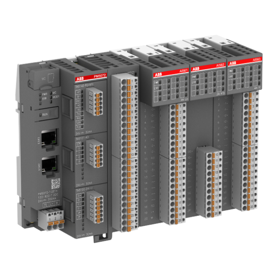
- Page 67 Device specifications Processor modules > PM50xx Fig. 4: Example: PM5072-T-2ETH 5 LEDs to display the states of the processor module (Power, Error, Run, MC, MOD1) Micro memory card slot Option board cover for option board slot 13-pin terminal block for I/O connectors 12-pin terminal block for I/O connectors 12 LEDs to display the states of the signals 10 LEDs to display the states of the signals...
- Page 68 Device specifications Processor modules > PM50xx 6.1.1.1 Short description The processor modules PM50xx series are the central units of AC500-eCo V3 PLC. Their main characteristics are: ● Power supply 24 V DC ● I/O bus (not for PM5012-x-ETH) ● Real time clock (PM5012-x-ETH needs additional RTC option board) ●...
- Page 69 Device specifications Processor modules > PM50xx Processor Glob Allocated Cycle Numer Number Type of Config- Number Max. module global time for digital digital digital urable of option number user user 1000 inputs outputs outputs digital board of I/O memory instructio inputs/ slots modules...
- Page 70 Table 7: Removable terminal block for the supply voltage 24 V DC 3-pin spring terminal block 3-pin screw terminal block The terminal block is available as a set for AC500-eCo V3 processor modules. Basic CPU (PM5012) Standard CPUs (PM5032, PM5052) and...
- Page 71 Faulty wiring on power supply CAUTION! terminals Risk of damaging the AC500-eCo V3 processor module and the connected modules! Voltages > 30 V DC might damage the processor module and the connected modules. Make sure that the supply voltage never exceeds 30 V DC.
- Page 72 Device specifications Processor modules > PM50xx State Color LED = ON LED = OFF LED flashing Error indica- An error No errors or Fast flashing tion occurred only warnings (4 Hz) dis- encountered plays together (E4 errors). with the RUN LED a cur- The LED rently running...
- Page 73 FB PmLedSet User configu- The AC500-eCo V3 processor module also provides 2 LEDs below the state LEDs which can rable LEDs be used by user and driven by an application. The LEDs can be used into a project and controlled using special function blocks which are con- tained in the PM AC500 library.
- Page 74 Device specifications Processor modules > PM50xx Processor State Color LED = ON LED = OFF module C12, C13 Digital configu- Yellow Input/Output Input/Output is rable input/ is ON output PM5072-T-2ETH I0..I11 Digital input Yellow Input is ON Input is OFF PM5072- O0..O7 Transistor...
- Page 75 Device specifications Processor modules > PM50xx 6.1.1.7 Onboard I/Os The AC500-eCo V3 processor modules have onboard I/Os which provide several functionalities. According to the CPU type, the number or the functionality of the onboard I/Os can be different. 6.1.1.7.1 Intended purpose...
- Page 76 Device specifications Processor modules > PM50xx Processor module No. and type of dig- No. and type of dig- No. and type of con- ital inputs ital outputs figurable inputs/ outputs PM5072-T-2ETH 24 V DC 0.5 A max., transistor 24 V DC input or (one isolation group) (one isolation group) 0.5 A max., transistor...
- Page 77 Device specifications Processor modules > PM50xx Parameter Value PM5012-T-ETH PM5012-R-ETH PM5032-T-ETH PM5032-R-ETH PM5052-T-ETH PM5052-R-ETH PM5072- T-2ETH(W) Functionality of 4 fast output 4 DO-R 4 fast output 6 DO-R digital outputs DO-T DO-T 24 V DC / 240 V 24 V DC / 240 V 24 V DC/0.5 A AC 2A in 2 24 V DC (100...
- Page 78 Device specifications Processor modules > PM50xx Parameter Value PM5012-T-ETH PM5012-R-ETH PM5032-T-ETH PM5032-R-ETH PM5052-T-ETH PM5052-R-ETH PM5072- T-2ETH(W) Digital inputs/ outputs, configurable Functionality of 2 DC 24 V DC 2 DC 24 V DC digital inputs/ ● 2 standard usable as outputs, I/Os configurable ●...
- Page 79 Device specifications Processor modules > PM50xx NOTICE! Risk of damaging the PLC modules! Overvoltages and short circuits might damage the PLC modules. – Make sure that all voltage sources (supply voltage and process supply voltage) are switched off before you begin with operations at the system. –...
- Page 80 Device specifications Processor modules > PM50xx Terminal Signal Description Normally-open relay contact of the output NO2 Normally-open relay contact of the output NO3 R2..3 Output common for signals NO2 to NO3 Table 12: Assignment of the terminals for PM5032-T-ETH, PM5052-T-ETH and PM5072- T-2ETH(W): Terminal Signal...
- Page 81 Device specifications Processor modules > PM50xx Table 13: Assignment of the terminals for PM5032-R-ETH and PM5052-R-ETH: Terminal Signal Description COM 0..11 Input common for digital input signals DI0 to DI11 Digital input signal DI0 (5 kHz) Digital input signal DI1 (5 kHz) Digital input signal DI2 (5 kHz) Digital input signal DI3 (5 kHz) Digital input signal DI4 (100 kHz)
- Page 82 Device specifications Processor modules > PM50xx PM5012-T-ETH PM5012-R-ETH PM5032-ETH PM5032-R-ETH PM5052-T-ETH PM5052-R-ETH PM5072-T-2ETH(W) 3ADR010635, 2, en_US 2021/06/29...
- Page 83 Device specifications Processor modules > PM50xx Connection of the digital inputs The digital inputs can be used as source inputs or as sink inputs. NOTICE! Risk of malfunctions in the plant! A ground closure, e. g. caused by a damaged cable insulation, can bridge switches accidentally.
- Page 84 Device specifications Processor modules > PM50xx Connection of the digital transistor outputs (PM50xx-T-ETH only) Fig. 5: Electrical connection of digital transistor outputs CAUTION! Risk of damaging the processor module! The outputs are not protected against short circuit and overload. – Never short-circuit or overload the outputs.
- Page 85 Device specifications Processor modules > PM50xx Fig. 6: Electrical connection of digital relay outputs (24 VDC) WARNING! Risk of death by electric shock! Hazardous voltages can be present at the terminals of the module. Make sure that all voltage sources (supply voltage and process supply voltage) are switched off before you begin with operations at the system.
- Page 86 Device specifications Processor modules > PM50xx CAUTION! Risk of damaging the processor module! – Never short-circuit or overload the outputs. – Never connect inductive loads without an external suppression against voltage peaks due to inductive kickback. – Never connect voltages > 240 V. All outputs must be fed from the same phase.
- Page 87 Device specifications Processor modules > PM50xx Class Comp Dev PS501 PLC Browser <− Display in Class Inter- Device Module Channel Error- Error message Remedy face Identifier Invalid configuration value for Correct frequency PWM channel. Frequency / cycletime for the PWM channel of the 8DI+6DO and 8DI+6DO +2AI+1AO module are common and if both channels are config-...
- Page 88 For AC500-eCo V3 devices the function "fast counter" is available in onboard I/Os of PM50xx. The AC500-eCo V3 processor modules with onboard I/Os provide some special functionality on the digital inputs or digital outputs. Fast counter, encoder inputs, interrupt inputs or PWM/PTO outputs are available depending on the device used.
- Page 89 Device specifications Processor modules > PM50xx Further information: Operating modes of the fast counter: Configurarion of the fast counter: Parameter PM5012-T-ETH PM5012-R-ETH PM5032-T-ETH PM5032-R- PM5052-T-ETH PM5052-R- PM5072- T-2ETH Fast counter Useable inputs Fast input DI4 ... DI5 DI4 ... DI5 max.
- Page 90 Device specifications Processor modules > PM50xx Parameter PM5012-T-ETH PM5012-R-ETH PM5032-T-ETH PM5032-R- PM5052-T-ETH PM5052-R- PM5072- T-2ETH Fast input DI0 ... DI3 DI0 ... DI3 max. 5 kHz Fast input, DI6 ... DI7 DI6 ... DI7 max. 100 kHz When using the When using the A/B encoder on A/B encoder on...
- Page 91 Device specifications Processor modules > PM50xx Parameter Value Short-circuit-proof / Overload-proof Overload message Output current limitation Resistance to feedback against 24 VDC Connection of 2 outputs in parallel Not possible Max. cable length Shielded 500 m Unshielded 150 m Table 16: PM5032-T-ETH, PM5072-T-2ETH and PM5072-T-2ETHW Parameter Value Number of channels per module...
- Page 92 Device specifications Processor modules > PM50xx Parameter Value Max. cable length Shielded 500 m Unshielded 150 m Technical data of the digital relay outputs Table 17: PM5012-R-ETH Parameter Value Number of channels per module 4 normally-open relay outputs Distribution of the channels into groups 2 groups for 2 channels Galvanic isolation Yes, per group...
- Page 93 Device specifications Processor modules > PM50xx Parameter Value Short-circuit-proof / Overload-proof No, should be provided by an external fuse or circuit breaker Rated protection fuse (for each channel) 5 A fast Overload message Output current limitation Resistance to feedback against 24 V DC Connection of 2 outputs in parallel Not possible Life time of relay contacts (cycles)
- Page 94 Device specifications Processor modules > PM50xx Parameter Value Spark suppression with inductive AC loads Must be performed externally according to driven load specification Switching frequencies With resistive loads Max. 1 Hz With inductive loads On request With lamp loads Max. 1 Hz Short-circuit-proof / Overload-proof No, should be provided by an external fuse or circuit breaker...
- Page 95 Ordering data Table 19: Processor modules for AC500-eCo V3 Part no. Description Product life cycle phase *) 1SAP 122 600 R0072 PM5012-T-ETH, AC500-eCo V3 pro- Active cessor module, programmable logic controller 1 MB, 6DI/4DO-Transistor, Ethernet, 24 V DC, option slot...
- Page 96 Device specifications Processor modules > PM50xx Part no. Description Product life cycle phase *) 1SAP 123 500 R0072 PM5032-R-ETH, AC500-eCo V3 pro- Active cessor module, programmable logic controller 2 MB, 12DI/6DO-Relay/2DC, Ethernet, 24 V DC, 2x option slots 1SAP 124 000 R0072 PM5052-T-ETH, AC500-eCo V3 pro-...
- Page 97 Device specifications Processor modules > PM50xx Part no. Description 1SAP 187 400 R0001 TA5211-TSCL-B: screw terminal block set for AC500-eCo V3 CPU Basic screw front, cable side 5.00 mm pitch ● 1 removable 3-pin terminal block for power supply ●...
- Page 98 Device specifications Processor modules > PM50xx General data Parameter Value PM5012 PM5032 PM5052 PM5072 Power supply 24 V DC Connection of power supply Via removable 3-pin terminal Current consumption from power supply (max.) Transistor version 200 mA 340 mA 400 mA 420 mA Relay version 200 mA...
- Page 99 Device specifications Processor modules > PM50xx Parameter Value PM5012 PM5032 PM5052 PM5072 Cycle time per instructions (minimum) PM5012 PM5032 PM5052 PM5072 Binary 20 ns Word 50 ns Floating point 600 ns Program execution PM5012 PM5032 PM5052 PM5072 Cyclic min. configurable 10 ms 5 ms 2 ms...
- Page 100 Device specifications Processor modules > PM50xx Data of I/Os PM5012-x-ETH PM5032-x-ETH PM5052-x-ETH PM5072-T-2ETH Channels for relay version Rated voltage 240 V AC relay Nominal current 2 A resistive per relay channel Analog inputs Optional Analog outputs Optional Number of option board slots Usage of option Each slot can be used for all type of existing option boards, same option...
- Page 101 Ordering Data Table 21: Processor modules for AC500-eCo V3 Part no. Description Product life cycle phase *) 1SAP 122 600 R0072 PM5012-T-ETH, AC500-eCo V3 pro- Active cessor module, programmable logic controller 1 MB, 6DI/4DO-Transistor, Ethernet, 24 V DC, option slot...
- Page 102 Device specifications Processor modules > PM50xx Part no. Description Product life cycle phase *) 1SAP 123 500 R0072 PM5032-R-ETH, AC500-eCo V3 pro- Active cessor module, programmable logic controller 2 MB, 12DI/6DO-Relay/2DC, Ethernet, 24 V DC, 2x option slots 1SAP 124 000 R0072 PM5052-T-ETH, AC500-eCo V3 pro-...
-
Page 103: Option Boards
Option boards > TA5101-4DI - Digital input module option board Part no. Description 1SAP 187 400 R0001 TA5211-TSCL-B: screw terminal block set for AC500-eCo V3 CPU Basic screw front, cable side 5.00 mm pitch ● 1 removable 3-pin terminal block for power supply ●... - Page 104 5-pin terminal block for input signals 6.2.1.1 Intended purpose The device is used as an optional I/O extension module for AC500-eCo V3 CPUs (PM50x2). The inputs are group-wise electrically isolated from each other. All other circuitry of the module is electrically isolated from the inputs.
- Page 105 Device specifications Option boards > TA5101-4DI - Digital input module option board Table 23: Assignment of the terminals: Terminal Signal Description COM 0..3 Input common for signals I0 to I3 Input signal I0 Input signal I1 Input signal I2 Input signal I3 The internal power supply voltage for the module's circuitry is carried out via the connection to CPU.
- Page 106 Device specifications Option boards > TA5101-4DI - Digital input module option board The digital inputs can be used as source inputs or as sink inputs. NOTICE! Risk of malfunctions in the plant! A ground closure, e. g. caused by a damaged cable insulation, can bridge switches accidentally.
- Page 107 Device specifications Option boards > TA5101-4DI - Digital input module option board Name Value Internal Internal Default Min. Max. EDS Slot Index Value Value , Type Module ID Internal 6105 WORD 6105 65535 xx01 0x17D9 Ignore BYTE No (0x00) module Parameter Internal 1 - CPU...
- Page 108 Digital input Yellow Input is OFF Input is ON 6.2.1.8 Technical data The system data of AC500-eCo V3 apply Ä Chapter 6.4 “System data AC500-eCo V3” on page 154 Only additional details are therefore documented below. Parameter Value Galvanic isolation...
-
Page 109: Ta5105-4Dot - Digital Output Module Option Board
Device specifications Option boards > TA5105-4DOT - Digital output module option board Parameter Value Signal 0 -5 V...+3 V -3 V...+5 V Undefined signal -15 V...-5 V +5 V...+15 V Signal 1 -30 V...-15 V +15 V...+30 V Input current per channel Input voltage 24 V Typ. - Page 110 7-pin terminal block for output signals 6.2.2.1 Intended purpose The device is used as an optional I/O extension module for AC500-eCo V3 CPUs (PM50x2). The outputs are group-wise electrically isolated from each other. All other circuitry of the module is electrically isolated from the outputs.
- Page 111 Device specifications Option boards > TA5105-4DOT - Digital output module option board Table 24: Assignment of the terminals: Terminal Signal Description Not connected Output signal O0 Output signal O1 Output signal O2 Output signal O3 Process supply voltage UP +24 V DC Process supply voltage ZP 0 V DC The internal power supply voltage for the module's circuitry is carried out via the connection to CPU.
- Page 112 Device specifications Option boards > TA5105-4DOT - Digital output module option board NOTICE! Risk of damaging the PLC modules! Overvoltages and short circuits might damage the PLC modules. – Make sure that all voltage sources (supply voltage and process supply voltage) are switched off before you begin with operations at the system.
- Page 113 Device specifications Option boards > TA5105-4DOT - Digital output module option board 6.2.2.4 I/O configuration The module itself does not store configuration data. It receives its parameterization data from the CPU module during power-up of the system. Hence, replacing optional modules is possible without any re-parameterization via software. 6.2.2.5 Parameterization The arrangement of the parameter data is performed with Automation Builder software.
- Page 114 L+/M (supply voltages for the module) are switched ON) 6.2.2.8 Technical data The system data of AC500-eCo V3 apply Ä Chapter 6.4 “System data AC500-eCo V3” on page 154 Only additional details are therefore documented below. Parameter Value Process supply voltage UP...
- Page 115 Device specifications Option boards > TA5105-4DOT - Digital output module option board Parameter Value Rated value 24 V DC Current consumption via UP terminal 5 mA + max. 0.5 A per output Max. ripple Inrush current 0.000002 A Protection against reversed voltage Rated protection fuse for UP Recommended;...
- Page 116 Device specifications Option boards > TA5105-4DOT - Digital output module option board Parameter Value Lamp load (max.) Max. leakage current with signal 0 0.5 mA Output type Non-protected Protection type External fuse on each channel Rated protection fuse (for each channel) 3 A fast Demagnetization when inductive loads are Must be performed externally according to driven...
-
Page 117: Ta5110-2Di2Dot - Digital Input/Output Module Option Board
6.2.3.1 Intended purpose The device is used as an optional I/O extension module for AC500-eCo V3 CPUs (PM50x2). The inputs and outputs are group-wise electrically isolated from each other. All other circuitry of the module is electrically isolated from the inputs. - Page 118 Device specifications Option boards > TA5110-2DI2DOT - Digital input/output module option board The following block diagram shows the internal construction of the digital inputs and outputs: Table 25: Assignment of the terminals: Terminal Signal Description COM 0..1 Input common for signals I0 to I1 Input signal I0 Input signal I1 Output signal O0...
- Page 119 Device specifications Option boards > TA5110-2DI2DOT - Digital input/output module option board NOTICE! Risk of damaging the PLC modules! Overvoltages and short circuits might damage the PLC modules. – Make sure that all voltage sources (supply voltage and process supply voltage) are switched off before you begin with operations at the system.
- Page 120 Device specifications Option boards > TA5110-2DI2DOT - Digital input/output module option board NOTICE! Risk of malfunctions in the plant! Only if L+/M of the CPU is available and the outputs are already configured in the AB program, then as soon as the UP/ZP is available, the outputs will switch This must be considered in the planning of the application.
- Page 121 Device specifications Option boards > TA5110-2DI2DOT - Digital input/output module option board ) with CS31 and addresses smaller than 70, the value is increased by 1 ) Value is hexadecimal: HighByte is slot (xx: 0...7), LowByte is index (1...n) GSD file: Ext_User_Prm_Data_Len = 0x03 Ext_User_Prm_Data_Const(0) =...
- Page 122 Digital output Yellow Output is OFF Output is ON 6.2.3.8 Technical data Ä Chapter 6.4 “System data AC500-eCo V3” The system data of AC500-eCo V3 apply on page 154 Only additional details are therefore documented below. Parameter Value Process supply voltage UP...
- Page 123 Device specifications Option boards > TA5110-2DI2DOT - Digital input/output module option board Parameter Value Indication of the input signals 1 yellow LED per channel; the LED is ON when the input signal is high (signal 1) Monitoring point of input indicator It is not part of input circuit (its controlled by processor side, not process side)
- Page 124 Device specifications Option boards > TA5110-2DI2DOT - Digital input/output module option board Parameter Value Output delay 0 to 1 50 µs 1 to 0 200 µs Output data length 1 byte Output current Rated current per channel (max.) 0.5 A at UP 24 V DC Rated current per group (max.) Rated current (all channels together, max.)
-
Page 125: Ta5141-Rs232I - Rs-232 Serial Adapter Isolated Option Board
Device specifications Option boards > TA5141-RS232I - RS-232 serial adapter isolated option board **) The needed spring terminal block is always delivered with the option board. The terminal block listed in the table is for spare part only if needed. 6.2.4 TA5141-RS232I - RS-232 serial adapter isolated option board 2 LEDs for communication state display (TxD and RxD) Allocation of signal name... - Page 126 ON (blinking) Transmitting Yellow ON (blinking) Receiving 6.2.4.4 Technical data The system data of AC500-eCo V3 apply Ä Chapter 6.4 “System data AC500-eCo V3” on page 154 Only additional details are therefore documented below. Parameter Value Protocol Programmable with Automation Builder e.g.
- Page 127 Value Interface connector 5-pin terminal block, male Usable CPUs PM50x2 Ambient temperature see: System data AC500-eCo V3 Internal power supply Via internal CPU connection Additional current consumption from 24 V DC Max. 25 mA power supply at CPU Weight Ca. 150 g 6.2.4.5...
-
Page 128: Ta5142-Rs485I - Rs-485 Serial Adapter Isolated Option Board
Device specifications Option boards > TA5142-RS485I - RS-485 serial adapter isolated option board 6.2.5 TA5142-RS485I - RS-485 serial adapter isolated option board 2 LEDs for communication state display (TxD and RxD) 2 LEDs for termination state display Allocation of signal name 5-pin terminal block for communication interface 6.2.5.1 Intended purpose... - Page 129 Device specifications Option boards > TA5142-RS485I - RS-485 serial adapter isolated option board Serial interface Signal Protocols Protocol Description Modbus Modbus RTU, master or slave CAA SerialCom Support for blocks contained in the CAA_SerialCom.lib library Bus cable Bus line Construction 2 cores, twisted, with common shield Conductor cross section >...
- Page 130 Device specifications Option boards > TA5142-RS485I - RS-485 serial adapter isolated option board Bus termination The line ends of the bus segment must be equipped with bus termination resistors. These resis- tors are integrated in the module TA5142-RS485I. The pull-up and pull-down settings must also be made on the circuit board of the module.
- Page 131 Device specifications Option boards > TA5142-RS485I - RS-485 serial adapter isolated option board Settings on the module State of Internal wiring Description LEDs diagram Master within the bus line, pull-up and pull-down activated Slave at the bus line end, bus termination 120 Ω 2021/06/29 3ADR010635, 2, en_US...
- Page 132 120R Yellow Bus termination Yellow Pull-up / Pull-down 6.2.5.4 Technical data Ä Chapter 6.4 “System data AC500-eCo V3” The system data of AC500-eCo V3 apply on page 154 Only additional details are therefore documented below. Parameter Value Protocol Programmable with Automation Builder e.g.
- Page 133 Programmable Interface connector 5-pin terminal block, male Usable CPUs PM50x2 Ambient temperature see: System data AC500-eCo V3 Internal power supply Via internal CPU connection Additional current consumption from 24 V DC Max. 25 mA power supply at CPU Weight Ca. 150 g 6.2.5.5...
-
Page 134: Ta5142-Rs485 - Rs-485 Serial Adapter Non Isolated Option Board
Device specifications Option boards > TA5142-RS485 - RS-485 serial adapter non isolated option board 6.2.6 TA5142-RS485 - RS-485 serial adapter non isolated option board 2 LEDs for communication state display (TxD and RxD) 2 LEDs for termination state display Allocation of signal name 5-pin terminal block for communication interface 6.2.6.1 Intended purpose... - Page 135 Device specifications Option boards > TA5142-RS485 - RS-485 serial adapter non isolated option board Serial interface Signal NC (not connected) Protocols Protocol Description Modbus Modbus RTU, master or slave CAA SerialCom Support for blocks contained in the CAA_SerialCom.lib library Bus cable Bus line Construction 2 cores, twisted, with common shield...
- Page 136 Device specifications Option boards > TA5142-RS485 - RS-485 serial adapter non isolated option board Bus termination The line ends of the bus segment must be equipped with bus termination resistors. These resis- tors are integrated in the module TA5142-RS485. The pull-up and pull-down settings must also be made on the circuit board of the module.
- Page 137 Device specifications Option boards > TA5142-RS485 - RS-485 serial adapter non isolated option board Settings on the module State of Internal wiring Description LEDs diagram Master within the bus line, pull-up and pull-down activated Slave at the bus line end, bus termination 120 Ω...
- Page 138 120R Yellow Bus termination Yellow Pull-up / Pull-down 6.2.6.4 Technical data Ä Chapter 6.4 “System data AC500-eCo V3” The system data of AC500-eCo V3 apply on page 154 Only additional details are therefore documented below. Parameter Value Protocol Programmable with Automation Builder e.g.
- Page 139 Programmable Interface connector 5-pin terminal block, male Usable CPUs PM50x2 Ambient temperature see: System data AC500-eCo V3 Internal power supply Via internal CPU connection Additional current consumption from 24 V DC Max. 25 mA power supply at CPU Weight Ca. 150 g 6.2.6.5...
-
Page 140: Ta5131-Rtc Option Board For Real Time Clock
6.2.7.1 Intended purpose This option board is only for the basic CPUs PM5012-T-ETH and PM5012-R- ETH. All other AC500-eCo V3 CPUs have the real-time clock already integrated. Information can be found in the chapter system technology: see 6.2.7.2 Functionality Information can be found in the chapter system technology: see 6.2.7.3... -
Page 141: Ta5130-Knxpb Option Board For Knx Address Switch
This option board is only intended to be used with PM5072-T-2ETH(W). This option board can only be used once on one slot at a time! The option board is not supported by other AC500-eCo V3 PLCs. Information can be found in the chapter system technology: see 6.2.8.2... -
Page 142: Accessories
Micro memory card adapter Memory card overview All AC500-eCo V3 processor modules have a micro memory card slot. All other processor modules (AC500 V2, AC500-eCo V2 and AC500 V3) have a memory card slot. When using the micro memory card for memory card slots in SD size, the sup- plied micro memory card adapter is required. - Page 143 For AC500 V3 the MC5102 micro memory card has to be used with the micro memory card adapter for memory card slot. For AC500-eCo V3 processor modules the MC5102 micro memory card has to be used without the micro memory card adapter. All AC500-eCo V3 processor modules have a micro memory card slot.
- Page 144 Device specifications Accessories > MC5102 - micro memory card with micro memory card adapter Fig. 7: Insertion: PM50xx AC500 V3 Unpack the micro memory card and insert it into the supplied micro memory card adapter. Insert the micro memory card adapter with integrated micro memory card into the memory card slot of the processor module until locked: 3ADR010635, 2, en_US 2021/06/29...
- Page 145 RUN LED does not blink. Otherwise the micro memory card and/or files on it might get corrupted and/or normal PLC operation might be disturbed. AC500-eCo V3 To remove the micro memory card, push on the micro memory card until it moves forward. By this, the micro memory card is unlocked and can be removed.
- Page 146 Device specifications Accessories > MC5102 - micro memory card with micro memory card adapter AC500 V3 To remove the micro memory card adapter with the integrated micro memory card, push on the micro memory card adapter until it moves forward. By this, the micro memory card adapter is unlocked and can be removed.
-
Page 147: Ta5300-Cvr Option Board Cover For Option Slot
For standard applications with AC500 V3 use the MC5102 micro memory card with micro memory card adapter for memory card slot. For standard applications with AC500-eCo V3 use the MC5102 micro memory card without miro memory card adapter for micro memory card slot. All AC500- eCo V3 processor modules have a micro memory card slot. - Page 148 Device specifications Accessories > TA5300-CVR Option board cover for option slot The AC500-eCo V3 are delivered with all slot covered with option board cover. The cover have to be removed before inserting an option board. The TA5300-CVR is intended only for spare parts...
-
Page 149: Pluggable Connectors For Screw And Spring Connection
*) Modules in lifecycle Classic are available from stock but not recommended for planning and commissioning of new installations. 6.3.3 Pluggable connectors for screw and spring connection Intended pur- Removable terminal blocks are used for power supply and for I/O connectors on AC500-eCo V3 pose processor modules. 2021/06/29... - Page 150 Device specifications Accessories > Pluggable connectors for screw and spring connection For the AC500-eCo V3 basic CPU a 3-pin terminal block for power supply and a 13-pin terminal block for I/O connectors are used. For the AC500-eCo V3 standard and pro CPUs a 3-pin terminal block for power supply, a 13- pin terminal block and a 12-pin terminal block for I/O connectors are used.
- Page 151 Table 27: Spring type terminal block for power supply Parameter Value Type TA5211-TSPF-B Removable 3-pin terminal block: TA5212-TSPF spring front/cable front 5.00 mm pitch Usage Power supply for AC500-eCo V3 processor modules Conductor cross section Solid 0.2 mm²...2.5 mm² Stripped conductor end 11 mm Degree of protection IP20...
- Page 152 Removable 13-pin terminal block: spring front/cable front 5.00 mm pitch TA5212-TSPF Removable 13-pin and 12-pin terminal block: spring front/cable front 5.00 mm pitch Usage Onboard I/Os for AC500-eCo V3 processor modules Conductor cross section Solid 0.2 mm²...2.5 mm² Stripped conductor end...
- Page 153 8-pin terminal block On request Ordering data Part no. Description 1SAP 187 400 R0001 TA5211-TSCL-B: screw terminal block set for AC500-eCo V3 CPU Basic screw front, cable side 5.00 mm pitch ● 1 removable 3-pin terminal block for power supply ●...
-
Page 154: System Data Ac500-Eco V3
Device specifications System data AC500-eCo V3 > Environmental conditions Part no. Description 1SAP 187 400 R0014 TA5220-SPF7: spring terminal block, removable, 7-pin, spring front, cable front, 6 pieces per packing unit 1SAP 187 400 R0015 TA5220-SPF8: spring terminal block, removable, 8-pin, spring front, cable front, 6 pieces per packing unit 6.4 System data AC500-eCo V3... -
Page 155: Creepage Distances And Clearances
Device specifications System data AC500-eCo V3 > Electromagnetic compatibility 6.4.2 Creepage distances and clearances The creepage distances and clearances meet the requirements of the overvoltage category II, pollution degree 2. 6.4.3 Insulation test voltages, routine test According to EN Parameter... -
Page 156: Mechanical Data
Device specifications System data AC500-eCo V3 > Approvals and certifications Electromagnetic Compatibility Immunity against transient interference vol- According to IEC 61000-4-4, zone B, crite- tages (burst): rion B Supply voltage units (DC) 2 kV Digital inputs/outputs (24 VDC) 1 kV Digital inputs/outputs (120 VAC...240 VAC) -
Page 157: Installation
Device specifications Installation > Mechanical dimensions 6.5 Installation 6.5.1 Mechanical dimensions 6.5.1.1 Switchgear cabinet assembly Information on EMC-conforming assembly and construction is provided within the overall functions section. PLC enclosure NOTICE! PLC damage due to wrong enclosures Due to their construction (degree of protection IP 20 according to EN 60529) and their connection technology, the devices are suitable only for operation in enclosed switchgear cabinets. - Page 158 Device specifications Installation > Mechanical dimensions Fig. 9: Installation of AC500-eCo V3 CPU/S500 modules in a switch-gear cabinet Cable duct Distance from cable duct ≥20 mm Mounting plate, earthed NOTICE! Horizontal mounting is highly recommended. Vertical mounting is possible, however, derating consideration should be made to avoid problems with poor air circulation and overheating.
- Page 159 Device specifications Installation > Mechanical dimensions Fig. 10: Side, front and back view 6.5.1.3 Mechanical dimensions S500-eCo All mechanical dimensions are given in millimeters and inches. The value in brackets is the inch-value. Fig. 11: Side, front and back view 2021/06/29 3ADR010635, 2, en_US...
-
Page 160: Mounting And Demounting
Device specifications Installation > Mounting and demounting 6.5.2 Mounting and demounting The control system is designed to be mounted to a well-grounded mounting surface such as a metal panel. Additional grounding connections from the mounting tabs or DIN rail (if used), are not required unless the mounting surface cannot be grounded. - Page 161 Device specifications Installation > Mounting and demounting Attach I/O module by hand to an other module. The serial I/O bus is connected automati- cally. Demounting I/O modules mounted on a DIN rail Remove I/O module by hand if connected. 2021/06/29 3ADR010635, 2, en_US...
- Page 162 Device specifications Installation > Mounting and demounting While pressing down I/O module pull it away from DIN rail. Mounting I/O modules on a NOTICE! metal plate Risk of function faults! Missing electrical contact by isolating screws or washers! Use metal screws on the metal plate. The metal plate must be included into the earthing concept of the plant.
- Page 163 Device specifications Installation > Mounting and demounting Attach the I/O module by hand to an other module. The serial I/O bus is connected auto- matically. Fasten the I/O module with two screws (max. diameter: 4 mm) to the metal plate. 2021/06/29 3ADR010635, 2, en_US...
-
Page 164: Connection And Wiring
Device specifications Installation > Connection and wiring Demounting I/O modules mounted on a metal plate Remove the 2 screws. Remove the I/O module from the connected module by hand. 6.5.3 Connection and wiring For detailed information such as technical data of your mounted devices (AC500 product family) refer to the hardware device specification of the appropriate device. - Page 165 Table 32: Removable terminal block for the supply voltage 24 VDC 3-pin spring terminal block 3-pin screw terminal block The terminal block is available as a set for AC500-eCo V3 processor modules. Basic CPU Standard and pro CPUs Spring type...
- Page 166 Faulty wiring on power supply CAUTION! terminals Risk of damaging the AC500-eCo V3 processor module and the connected modules! Voltages > 30 VDC might damage the processor module and the connected modules. Make sure that the supply voltage never exceeds 30 VDC.
-
Page 167: Handling Of Accessories
Device specifications Installation > Handling of accessories Ethernet interface The Ethernet interface is carried out via a RJ45 jack. The pin assignment of the Ethernet inter- face: Interface Description Transmit Data + Transmit Data - Receive Data + Not connected Not connected Receive Data - Not connected... - Page 168 Device specifications Installation > Handling of accessories Technical Data Parameter Value Weight Dimensions 12 mm x 8.5 mm x 10 mm Ordering Data Part no. Description Product life cycle phase *) 1SAP 182 800 R0001 TA543, screw mounting Active accessory for PM595 *) For planning and commissioning of new installations use modules in Active status only.
-
Page 169: Software Handling And Programming
It can be found in the complete documentation for AC500-eCo V3 on our website. For an easy access to the complete documentation refer to chapters “About this document è Documentation structure” and “About this document è... -
Page 170: Simple Motion
— 8 Simple motion 8.1 Introduction The AC500-eCo V3 PLC provide several HW and SW features allowing to realize some motion application. Specific fast onboard I/O and dedicated SW library function blocks (simple motion) are available and can manage up to 2x Axis on the CPU. -
Page 171: Hardware Components For Motion Control
Simple motion Hardware components for motion control > Basic CPU – PM5012-R-ETH and PM5012-T-ETH 8.2 Hardware components for motion control 8.2.1 Basic CPU – PM5012-R-ETH and PM5012-T-ETH Fig. 12: Example: PM5012-T-ETH 2021/06/29 3ADR010635, 2, en_US... -
Page 172: Standard And Pro Cpu - Pm5032-X-Eth / Pm5052-X-Eth / Pm5072-T-2Eth
The digital configurable inputs/outputs can be used for PTO/PWM functions. 8.3 System technology The following chapters describe the system technology of the AC500-eCo V3 using motion examples. The simple motion set of function blocks is standard part of the system libraries for AC500-eCo... -
Page 173: Use The Onboard I/Os As Encoder With A And B Signals
Simple motion System technology > Use the onboard I/Os as encoder with A and B signals 8.3.1 Use the onboard I/Os as encoder with A and B signals 8.3.1.1 Parameter configuration The onboard I/O accept encoder signal A and B. When configure the encoder track A, the encoder track B will be automatically inserted. - Page 174 Simple motion System technology > Use the onboard I/Os as encoder with A and B signals 8.3.1.2 Function block OBIOEncoder Counter If “Enable” is TRUE, the “OBIOEncoderCounter” instruction increments the counter by one base on the input. If “Set” bit is TRUE, the “OBIOEncoderCounter” instruction moves the “CounterValueSet” to the “CounterValue”.
- Page 175 Simple motion System technology > Use the onboard I/Os as encoder with A and B signals After “CounterValue” reaches the “LimitValueMax”, the “OBIOEncoderCounter” instruction writes 0 to the “CounterValue”. “Encoder Counter Mode”: 0 = “90° Mode”. In this encoder counter mode, an increasing count results when input B is 90° ahead of input A. The count is initiated on the rising edge of input A, and the direction of the encoder is clockwise (positive).
- Page 176 Simple motion System technology > Use the onboard I/Os as encoder with A and B signals If “Enable” is TRUE, the “OBIOEncoderCounter” instruction increments the counter by one based on the input. If “EnableRef” bit is TRUE, the “OBIOEncoderCounter” instruction is ready to receive the touch/ reset input.
-
Page 177: Use The Onboard I/Os As Forward Counter
Simple motion System technology > Use the onboard I/Os as forward counter 8.3.2 Use the onboard I/Os as forward counter 8.3.2.1 Parameter configuration The Onboard I/O accept pulse input as forward counter. User can configure the following input channel as forward counter. ●... -
Page 178: Use The Onboard I/Os As Interrupt Input With Dedicated Interrupt Task
Simple motion System technology > Use the onboard I/Os as interrupt input with dedicated interrupt task 8.3.2.2 Function block OBIOForward Counter If “Enable” is TRUE, the “OBIOForwardCounter” instruction increments the counter by one based on the input. If “Set” bit is TRUE, the “OBIOForwardCounter” instruction moves the “CounterSetValue” to the “CounterValue”. - Page 179 Simple motion System technology > Use the onboard I/Os as interrupt input with dedicated interrupt task The user can configure the following input channel as interrupt input. ● Interrupt input 0 : Input Channel 0 ● Interrupt input 1 : Input Channel 1 ●...
-
Page 180: Use The Onboard I/Os As Output Limit Switch
Simple motion System technology > Use the onboard I/Os as output limit switch 8.3.3.2 Function block The “OBIOInterruptPara” instruction is configured for 4 interrupt inputs. if “EnableInterrupt” bit is TRUE, the “OBIOInterruptInfo” instruction is ready to receive the inter- rupt input. If the interrupt input is TRUE, the interrupt task will be executed. -
Page 181: Using Pto Hw Channels)
Simple motion System technology > Use the onboard I/Os as PTO (pulse-train output) with 100 kHz frequency (max. 2 PTO using PTO HW channels) See also the following chapter: 8.3.4.2 Function block If the counter value reaches the “LowerLimitOn” preset, it will write to the LimitSwitch output based on the signal until the “UpperLimitOn”... - Page 182 Simple motion System technology > Use the onboard I/Os as PTO (pulse-train output) with 100 kHz frequency (max. 2 PTO using PTO HW channels) The input “CwCCw” of the function block “OBIOPulseTrainOutput” determines the output 5 and 7 as “CounterClockWise” or “Direction” if it is set as PTO. See also the following chapter: 8.3.5.2 Function block...
- Page 183 Simple motion System technology > Use the onboard I/Os as PTO (pulse-train output) with 100 kHz frequency (max. 2 PTO using PTO HW channels) If the input “CwCCw” of the “OBIOPulseTrainOutput” is set to FALSE, the PTO output channel B is toggled based on the direction.
-
Page 184: Use The Onboard I/Os As Pto (Pulse-Train Output) With 200 Khz Frequency (Max. 2 Pto Using Pto Hw Channels) And Simple Motion Obiomotionpto Function Block
Simple motion System technology > Use the onboard I/Os as PTO (pulse-train output) with 200 kHz frequency (max. 2 PTO using PTO HW channels) and Simple Motion OBIOMotionPTO function block 8.3.6 Use the onboard I/Os as PTO (pulse-train output) with 200 kHz frequency (max. 2 PTO using PTO HW channels) and Simple Motion OBIOMotionPTO function block 8.3.6.1 Parameter configuration... -
Page 185: Using Pwm Hw Channels) And Simple Motion Obiomotionpwm Function Bloc
Simple motion System technology > Use the onboard I/Os as PTO (pulse-train output) with 100 kHz frequency (Max. 4 PTO using PWM HW channels) and Simple Motion OBIOMotionPWM function bloc If the input “CwCCw” of the “OBIOMotionPTO” is set to FALSE, the PTO output channel B is toggled based on the direction. - Page 186 Simple motion System technology > Use the onboard I/Os as PTO (pulse-train output) with 100 kHz frequency (Max. 4 PTO using PWM HW channels) and Simple Motion OBIOMotionPWM function bloc The user must configure the following output channels as PWM outputs and use the “OBIOMotionPWM”...
-
Page 187: Use The Onboard I/Os As Output Pwm (Pulse-Width Modulation)
Simple motion System technology > Use the onboard I/Os as output PWM (pulse-width modulation) 8.3.8 Use the onboard I/Os as output PWM (pulse-width modulation) 8.3.8.1 Parameter configuration The user can configure the following output channels as PWM (pulse-width modulation). ● “PWM 0”: Output channel 0 ●... -
Page 188: Function Block Description
Simple motion Function block description > Use the onboard I/Os as output PWM (pulse-width modulation) The duty cycle ratio of the “PWM” is based on the formula = T / (T 8.4 Function block description Function block descriptions of all V3 libraries are available in the library manager. 3ADR010635, 2, en_US 2021/06/29... - Page 189 Select “Add Library”. ð A list of all available libraries is displayed. Libraries in folder “ABB - AC500” are created by ABB and tested in combination with Automation Builder. We recommend to use libraries of subfolder “Use Cases” for your project.
-
Page 190: Ac500-Eco V3 Option Board Slots For Processor Modules Pm50Xx
Simple motion AC500-eCo V3 option board slots for processor modules PM50xx > Use the onboard I/Os as output PWM (pulse-width modulation) 8.5 AC500-eCo V3 option board slots for processor modules PM50xx Depending on the processor module type, up to three option board slots are available on the CPU for different purpose like digital or analog I/O extension, serial interface or special module for specific functionality. -
Page 191: Option Board For Serial Interface Extension
Simple motion AC500-eCo V3 option board slots for processor modules PM50xx > Option board for digital I/O extension Usable option boards Basic CPU Standard CPU Pro CPU onAC500-eCo V3 PM5012-x-ETH PM5032-x-ETH PM5052-x-ETH PM5072-T-2ETH TA5101-4DI TA5105-4DOT TA5110-2DI2DOT TA5120-2AI-UI TA5122-2AI-TC TA5123-2AI-RTD TA5126-2AO-UI... -
Page 192: Option Board For Specific Function
24 VDC, 2DO-T 24 VDC / 0.5 A, spring/cable front terminal 3.50 mm pitch 8.6 Option board for specific function The TA5130-KNXPB can only be used on AC500-eCo V3 processor modules Pro PM5072-T-ETH(W). The TA5131-RTC can only be used on AC500-eCo V3 processor modules Basic PM5012-x-ETH. -
Page 193: Contact Abb
If you have questions on a PLC product you receive further information on http://www.abb.com/plc. If you have questions on any ABB product you receive further contact information for your spe- cific device in the ABB global sales contact directory:http://www.abb.com/contacts. Service - control ABB operates a technical support center to assist in the case of problems. -
Page 194: Index
Automation Builder and AC500 AC500-eCo V3 products ....22 IP address ....... 18 log-in to a CPU . - Page 195 — ABB Automation Products GmbH Eppelheimer Str. 82 69123 Heidelberg, Germany Telephone: +49 (0)6221 701 1444 Fax: +49 (0)6221 701 1382 E-mail: plc.support@de.abb.com abb.com/plc — © Copyright 2021 ABB. We reserve all rights in this document and in the information contained therein. Reproduction, use or disclosure to third parties without express...
Need help?
Do you have a question about the AC500-eCo V3 and is the answer not in the manual?
Questions and answers