Siemens SIMOCODE pro System Manual
Motor management and control devices
Hide thumbs
Also See for SIMOCODE pro:
- Function manual (344 pages) ,
- Programming and operating manual (286 pages) ,
- Operating manual (278 pages)

Related Manuals for Siemens SIMOCODE pro


Summary of Contents for Siemens SIMOCODE pro
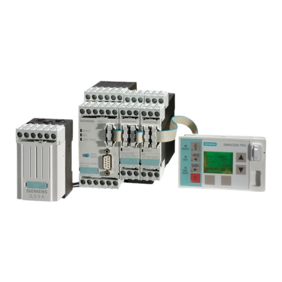
- Page 1 Motor Management and Control Devices SIMOCODE pro System Manual 05/2011 • Industrial Controls Answers for industry.
-
Page 3: Table Of Contents
Safety guidelines Table of contents Important information System description Short instructions for configuring a reversing starter Motor protection SIMOCODE®pro Motor control Monitoring functions Outputs Inputs Analog value recording System manual 3UF50 compatibility mode Standard functions Logic modules Communication Mounting, wiring, interfaces Commissioning and servicing Alarms, faults and system events Tables... - Page 4 Note the following: Warning Siemens products may only be used for the applications described in the catalog and in the relevant technical documentation. If products and components from other manufacturers are used, these must be recommended or approved by Siemens. Proper transport, storage, installation, assembly, commissioning, operation and maintenance are required to ensure that the products operate safely and without any problems.
-
Page 5: Table Of Contents
Current measuring module (IM) for the SIMOCODE pro C and SIMOCODE pro V device series ......1-93 1.7.5... -
Page 6: Motor Protection
Operating hours monitoring ......5-19 SIMOCODE pro GWA 4NEB 631 6050-22 DS 03... -
Page 7: Outputs
Counter ........11-8 SIMOCODE pro... - Page 8 Evaluating diagnostics data......12-21 12.6.1 SIMOCODE pro integrated with GSD ..... . 12-21 12.6.2 Integration of SIMOCODE pro in SIMATIC S7 with OM SIMOCODE ES .
- Page 9 Securing and saving parameters ......14-9 14.3.3 Replacing SIMOCODE pro components ..... 14-11 14.3.4 Resetting the factory settings .
-
Page 10: Dimension Drawings
C.1.2 SIMOCODE pro V 3UF7010 basic unit ..... . 3UF710 current measuring module ...... -
Page 11: Example Circuits
"Reversing starter" circuit diagram ......E.4.2 "Reversing starter" function circuit diagram ....SIMOCODE pro GWA 4NEB 631 6050-22 DS 03... - Page 12 Circuit diagram "Soft starter with reversing contactor" (3RW405, 3RW407) ....... . . E-48 SIMOCODE pro viii...
- Page 13 Setting the rated motor current ......F.2.2 SIMOCODE pro with thermistor input ..... . F.2.3 Sensor circuit wiring .
- Page 14 Table of contents SIMOCODE pro GWA 4NEB 631 6050-22 DS 03...
-
Page 15: Inputs
Important information Purpose of this manual The SIMOCODE pro system manual describes in detail the motor management system and its functions. It contains information about configuring, commissioning, service and maintenance. The user is introduced to the system quickly and practically using a typical reversing starter application as an example. -
Page 16: Important Information
We reserve the right to include updated information about new components or new versions of components in a product information. Definitions • When "SIMOCODE pro" is referred to, both the "SIMOCODE pro C" and the "SIMOCODE pro V" series are meant. SIMOCODE pro response tables Specific responses (deactivated, signaling, warning, tripping) can be parameterized for various SIMOCODE pro functions, such as overload. - Page 17 Siemens AG, its subsidiaries and associated companies (herein referred to as "Siemens") are not in a position to guarantee every characteristic of a complete plant or machine not designed by Siemens.
- Page 18 Important information SIMOCODE pro GWA 4NEB 631 6050-22 DS 03...
-
Page 19: System Description
This chapter is addressed to the following target groups: • Planners and configurators • People who are now using SIMOCODE DP but wish to use SIMOCODE pro as a replacement or additional system in the future • Optional for commissioners, maintenance and service personnel as additional information "about SIMOCODE pro"... -
Page 20: Introduction
SIMOCODE pro is installed in the low voltage switchgear system and links the higher-level automation system and the motor feeder (via PROFIBUS DP) intelligently. It comprises the following functions: •... - Page 21 (operating, service and diagnostics data (overload, thermistor, earth-fault …) (including monitoring + interlocks) + control commands) Fig. 1-1: SIMOCODE pro integrated in the main circuit, control circuit and at automation level (PLC) SIMOCODE pro GWA 4NEB 631 6050-22 DS 03...
- Page 22 "Failsafe Digital Module SIMOCODE pro Safety"). Recording of measured curves: SIMOCODE pro is able to record measured curves and can, for example, illustrate the flow of the motor current during motor startup. See Chapter "Analog value recording" Flexible motor control with integrated control functions...
- Page 23 Chapter 4.2.15 Chapter 4.2.16). These control functions are pre-defined in SIMOCODE pro and can be assigned freely to device inputs and outputs (including PROFIBUS DP). These pre-defined control functions can also be adjusted flexibly to meet customer requirements of the motor feeder, without requiring additional auxiliary relays in the control circuit.
-
Page 24: Information For Eex Areas
Further applications include power plant engineering and diamond, gold and platinum mines. SIMOCODE pro has been designed to meet the requirements of these industries even more accurately, based on experiences with the previous system (SIMOCODE DP). The availability of motors and thus the entire process plays an important role in these industries. - Page 25 Besides the existing inputs and outputs present, additional inputs, outputs, and functions can be added to basic unit 2 (SIMOCODE pro V) by means of optional expansion modules. All modules can be connected to each other via connecting cables.
- Page 26 System description Independent operation SIMOCODE pro C and pro V protect and control the motor feeder independently of the automation system. Even if the automation system (PLC) fails, or if communication is disrupted, the motor feeder remains fully protected and controllable. SIMOCODE pro can be used without being connected to PROFIBUS DP .
-
Page 27: Simplifying Configuration With Simocode Pro
System description Simplifying configuration with SIMOCODE pro Conventional configuration without SIMOCODE pro Individual components are used for control, monitoring and signal pre- processing. The following components are to be used and the following wiring is to be carried out: • Insertion and wiring of overload relays, thermistor evaluation devices, current transformers and analog/digital converters •... - Page 28 Current measuring module (IM) Basic unit (BU) OUT 1 1 3 5 N/L– - Q1 2 4 6 Thermistor Fig. 1-4: Configuration of a load feeder (direct starter) with SIMOCODE pro SIMOCODE pro 1-10 GWA 4NEB 631 6050-22 DS 03...
-
Page 29: Application Example
The fill level (actual value) is measured by the fill level indicator and output as an analog signal. When the fill level sinks below a specific level, the pump is switched on by SIMOCODE pro. Liquid is pumped in until the reference value is re-attained. The pump is then switched off. - Page 30 • The analog value of the fill-level indicator, which is measured by the analog module. The measured values are evaluated directly by SIMOCODE pro and/or transferred via PROFIBUS DP to the PLC/PCS. Any measured value can be output via the analog module, e.g. the effective motor current on a connected pointer instrument.
-
Page 31: Check List For Selecting A Device Series
More than 4 binary inputs required ✓ (maximum 12) — Table 1-1: Check list for selecting a device series 1) Via current measuring module 2) With expansion modules 3) Via current/voltage measuring modules SIMOCODE pro 1-13 GWA 4NEB 631 6050-22 DS 03... - Page 32 OFF buttons (local or decentralized via — PROFIBUS DP) Table 1-1: Check list for selecting a device series (Cont.) 1) Via current measuring module 2) With expansion modules 3) Via current/voltage measuring modules SIMOCODE pro 1-14 GWA 4NEB 631 6050-22 DS 03...
-
Page 33: Overview Of Functions
1) 5) • External earth-fault monitoring for SIMOCODE pro V In the case of networks that are grounded with a higher impedance it may be necessary to set up the earth-fault monitoring for smaller earth-fault currents... - Page 34 Monitoring operating hours, motor stop time and number of starts In order to avoid plant downtimes due to failed motors that were either running too long (wear) or stopped for too long, both SIMOCODE pro C and SIMOCODE pro V can monitor operating hours and motor stop times.
- Page 35 Phase sequence identification SIMOCODE pro allows the direction of rotation of a motor to be determined by identification of the phase sequence. If the direction of rotation is wrong, a signal can be generated or the motor switched off.
- Page 36 System description Safety-oriented tripping The SIMOCODE pro V motor management system has been extended by 2 modules/safety relays for the safety-oriented tripping of motors: • Failsafe digital module DM-F Local: For applications that require the safety-oriented tripping of a motor feeder via a hardware signal that is detected and analyzed by the module.
-
Page 37: Control Functions
All the necessary protection functions and interlocks are already available and can be flexibly adapted and expanded. For a detailed description of the individual control functions: See Chapter 4 "Motor control". SIMOCODE pro 1-19 GWA 4NEB 631 6050-22 DS 03... -
Page 38: Communication
System description 1.5.4 Communication PROFIBUS DP SIMOCODE pro has an integrated PROFIBUS DP interface (SUB-D socket or terminal connection on the basic units). SIMOCODE pro supports, for example, the following services: SIMOCODE Service pro C (BU1) pro V (BU2) ✓... -
Page 39: Additional Signal Processing With Freely-Programmable Logic Modules
These can be used, for example, to implement logical operations, time relay functions and counter functions. Furthermore, limit monitors can monitor any value in SIMOCODE pro for undershooting or overshooting of a freely selected limit. Depending on the device series, the system offers several, freely-... -
Page 40: Operating, Service And Diagnostic Data
(calculators) provided by SIMOCODE pro V. For example, the temperature recorded by SIMOCODE pro can be calculated in either °F or °C and transmitted to the automation system via PROFIBUS. - Page 41 • Device-internal error protocolling with time stamp • Value of the last trip current • Feedback faults (e.g. no current flow in the main circuit after switch-on command), etc. • Diagnostic message "Local" und PROFIsafe SIMOCODE pro 1-23 GWA 4NEB 631 6050-22 DS 03...
-
Page 42: Overview Of System Components
0.3 A - 3 A otherwise like current 2.4 A - 25 A measuring modules, also: - Voltage measurement - Power measurement - Cos phi measurement - Phase sequence Table 1-6: System components, devices SIMOCODE pro 1-24 GWA 4NEB 631 6050-22 DS 03... - Page 43 - Inputs: - 2 sensor circuits - Start signal - Cascade input - Feedback circuit - Safety function configurable via DIP switch Table 1-6: System components, devices (Cont.) SIMOCODE pro 1-25 GWA 4NEB 631 6050-22 DS 03...
- Page 44 (DCM) For a detailed description of the system components: See Chapter 1.7 "Description of system components". Dimension drawings: See Chapter C "Dimension drawings". Installation instructions: See Chapter 13 "Mounting, wiring, interfaces". SIMOCODE pro 1-26 GWA 4NEB 631 6050-22 DS 03...
- Page 45 PC Addressing plug Configuring the PROFIBUS DP address without a PC PC cable Connecting SIMOCODE pro to a PC USB to serial adapter For connecting a RS- 232 cable to the USB interface of a PC. Door adapter Only for leading out the system interface, e.g.
- Page 46 PCS 7 function block library SIMOCODE pro: AS blocks and faceplates for integrating SIMOCODE pro in the SIMATIC PCS 7 process control system Table 1-8: Software components SIMOCODE pro 1-28 GWA 4NEB 631 6050-22 DS 03...
-
Page 47: Description Of System Components
• 110 to 240 V AC/DC. Basic unit 1 (BU1) Basic unit 1 is the fundamental component of the SIMOCODE pro C device series and is used in combination with a current measuring module and optional operator panels. The following motor control functions are supported: •... - Page 48 • An operator panel. Basic unit 2 (BU2). Basic unit 2 is the fundamental component of the SIMOCODE pro V device series and is used in combination with a current measuring module or current/voltage measuring module and optional operator panels.
- Page 49 2 system interfaces for connecting • A current measuring module or a current/voltage measuring module • Expansion modules and • An operator panel. Supplying the inputs Chapter 13 "Mounting, wiring, interfaces". SIMOCODE pro 1-31 GWA 4NEB 631 6050-22 DS 03...
-
Page 50: Operator Panel (Op)
The operator panel is often installed in the front panels of motor control centers. It can be used with both the SIMOCODE pro C device series and the SIMOCODE pro V device series. It also contains all the status LEDs available on the basic unit and the Test/Reset button, and facilitates access to the system interface from outside the switchgear cabinet. - Page 51 Fig. 1-8: Labeling strips for operator panel buttons and LEDs Unused labeling strips can be stored on the back of the operator panel: Labeling strips Storage clips Fig. 1-9: Storage clips for labeling strips SIMOCODE pro 1-33 GWA 4NEB 631 6050-22 DS 03...
-
Page 52: Operator Panel With Display (Opd) For Simocode Pro V
Current measured values, status information, fault messages or the device- internal error protocol are simultaneously shown on the display. Notice: The operator panel can only be used with a basic unit 2 (SIMOCODE pro V) from version *E03*. Overall, the following are available: •... - Page 53 The operator panel with display may not be removed or plugged in during operation! Note When using an operator panel with display, the type and number of expansion modules that can be connected to a basic unit are limited! See Chapter 1.7.8. SIMOCODE pro 1-35 GWA 4NEB 631 6050-22 DS 03...
- Page 54 • 6 pre-assigned labeling strips and 1 individually inscribable labeling strip Button 1 Button 2 Button 3 Button 4 CLOSE OPEN OPEN STOP CLOSE Fig. 1-12: Labeling strips for the buttons of the operator panel with display SIMOCODE pro 1-36 GWA 4NEB 631 6050-22 DS 03...
- Page 55 Fig. 1-13: Storage clips for labeling strips "Park position" for memory module: The memory module can be "parked" on the front of the operator panel with display beneath the system interface: Fig. 1-14: Memory module "park position" SIMOCODE pro 1-37 GWA 4NEB 631 6050-22 DS 03...
- Page 56 Predefined profiles in the display settings can be selected for this purpose. When the "Menu" softkey on the right is pressed, the submenus of the main display can be navigated (see "Read and adapt main display"). SIMOCODE pro 1-38 GWA 4NEB 631 6050-22 DS 03...
- Page 57 Two arrow keys (up and down). These arrow keys can be used for menu navigation or for changing the display settings, e.g. contrast adjustment or selection of the main display profile. SIMOCODE pro 1-39 GWA 4NEB 631 6050-22 DS 03...
- Page 58 Statistics/maintenance Communication (PROFIBUS) Device I/Os Display settings Commands Status information Warnings Faults Error buffer Event memory (OPD above *E04* and BU2 above *E07*) Identification About SIMOCODE Fig. 1-17: Main menu (OPD) SIMOCODE pro 1-40 GWA 4NEB 631 6050-22 DS 03...
- Page 59 In 1[mA] / In 2 [mA] Max. temp. Max. temp. °C °F Temperatures °C Temperatures °F UL1-N, UL2-N, UL3-N UL1-L2, UL2-L3, UL3-L1 (OPD above *E04*) I_max, UL1-N, Cos Fig. 1-18: Main display (OPD) SIMOCODE pro 1-41 GWA 4NEB 631 6050-22 DS 03...
- Page 60 T1, T2, T3 [ T1, T2, T3 [ °C] °F] Thermal motor model [%] Time to trip [s] Cooling down period [s] Last trip current [A] Fig. 1-19: Measured values display (OPD) SIMOCODE pro 1-42 GWA 4NEB 631 6050-22 DS 03...
- Page 61 DM-F Local (OPD above *E04* and BU2 above *E07*) Safety DM-F PROFIsafe Enabling circuit Switch-off (OPD above *E04* and BU2 above *E07*) PROFIsafe o.k. Fig. 1-20: Status display motor protection/motor control (OPD) SIMOCODE pro 1-43 GWA 4NEB 631 6050-22 DS 03...
- Page 62 Motor stop time > Energy consumed [kWh] Number of parameterizations Operating hours basic unit [h] Timer Timer 2 - Actual value [s] Timer 1 (2,3,4) - Output Output Counters Fig. 1-21: Statistics/maintenance (OPD) SIMOCODE pro 1-44 GWA 4NEB 631 6050-22 DS 03...
- Page 63 Start-up parameter block Timestamping Active Compatibility mode Compatibility mode 1 3UF50 mode 3UF50 - Operating mode DPV0 DPV1 3UF50 basic type Diagnostics Device fault Event Diagnostics Warning Fault Fig. 1-22: PROFIBUS communication (OPD) SIMOCODE pro 1-45 GWA 4NEB 631 6050-22 DS 03...
- Page 64 Inputs (OPD above *E04* and BU2 above *E07*) Feedback circuit DM1 = DM-F PROFIsafe Outputs DM-F PROFIsafe (OPD above *E04* and BU2 above *E07*) Enabling circuit Fig. 1-23: Device I/Os (OPD) SIMOCODE pro 1-46 GWA 4NEB 631 6050-22 DS 03...
- Page 65 Faults 1 Do not display 2 Display Return to main display [Manual, 3 s, 10 s, 1 min, 5 min] Factory settings Display Restore display settings Fig. 1-24: Display settings (OPD) SIMOCODE pro 1-47 GWA 4NEB 631 6050-22 DS 03...
- Page 66 "Display of all pending status information". Thermistor trip Warning T> Fig. 1-26: Messages (OPD) 10 Warnings (OPD) For details: See "Display of all pending warnings". Thermistor trip Warning T> Fig. 1-27: Warnings (OPD) SIMOCODE pro 1-48 GWA 4NEB 631 6050-22 DS 03...
- Page 67 7 6 5 4 3 2 1 DM1 = DM-F PROFIsafe Enabling circuit 0 -> 1 PROFIsafe Address: DM1 = DM-F Local or DM-F PROFIsafe Enabling circuit 1 -> 0 Fig. 1-30: Event memory, OPD SIMOCODE pro 1-49 GWA 4NEB 631 6050-22 DS 03...
- Page 68 System description 14 Identification (OPD) For details see "Identification of the motor feeder and the SIMOCODE pro components". Display Plant identifier MLFB Display Location designation HW version Display FW version Date Comment MLFB Short code SIMOCODE pro V Manufacturer SIEMENS...
- Page 69 (e.g. type and number of expansion modules used). Main display The "Main display" is the default SIMOCODE pro display. It displays the current measured values, which can be selected via predefined profiles according to user requirements.
- Page 70 "Adapt display settings". Commands The "Commands" menu item contains all commands relating to SIMOCODE pro e.g. for testing the feeder, resetting after tripping and/or adopting parameters into the memory module or into SIMOCODE pro. For detailed information, see "Resetting, testing and parameterizing commands".
- Page 71 The "Faults" menu item provides an overview of all pending faults. For detailed information: See "Display of all pending faults". Error buffer The "Error buffer" menu item displays the SIMOCODE pro device- internal error buffer. For detailed information, see "Reading out the device-internal error buffer".
- Page 72 To enable users speedy viewing of the measured values typically shown on their switchgear, various profiles are deposited in the operator panel with display that enable user-specific adaption of the standard measured values displayed in the SIMOCODE pro main display. The profile can be selected in "Display settings" -> "Profile" (see Section "Adapt display settings"...
- Page 73 Note Only possible if a current/voltage measuring module is being used, line-to-line voltage is set/configured and the OPD used is above version *E04*. Table 1-10: Read and adapt main display (Cont.) SIMOCODE pro 1-55 GWA 4NEB 631 6050-22 DS 03...
- Page 74 Displays the individual temperatures of all used sensor measuring circuits of the temperature module in °C. Note Only possible if a temperature module is used. Table 1-10: Read and adapt main display (Cont.) SIMOCODE pro 1-56 GWA 4NEB 631 6050-22 DS 03...
- Page 75 Only possible if a current/voltage measuring module is being used. If an OPD above version *E04* is used: Values will only be displayed if phase voltage is set/ configured. Table 1-10: Read and adapt main display (Cont.) SIMOCODE pro 1-57 GWA 4NEB 631 6050-22 DS 03...
- Page 76 Note Only possible if a current/voltage measuring module is being used, line-to-line voltage is set/configured and the OPD used is above version *E04*. Table 1-10: Read and adapt main display (Cont.) SIMOCODE pro 1-58 GWA 4NEB 631 6050-22 DS 03...
- Page 77 Enables, for example, the depiction on the switchgear display of a 2-byte value sent directly from the automation system, i.e. the unitless depiction of all 2-byte values available in SIMOCODE pro. Calculator 2 (example) Displays the calculated result that the function block Calculator 2 provides, unitless in the range of 0 to 65535.
- Page 78 System description Display of measured values in the measured values display The "Measured Values" menu item displays all current SIMOCODE pro measured values. Depending upon the type of expansion modules used, all or only some of the values listed here will be available.
- Page 79 Only possible if a temperature module is being used. Thermal motor model (example) Displays current internal thermal motor model in %. Table 1-11: Display of measured values in the measured value display (Cont.) SIMOCODE pro 1-61 GWA 4NEB 631 6050-22 DS 03...
- Page 80 Displays the strength of the current that was measured at the moment of the overload trip, switchable between A and % of I Table 1-11: Display of measured values in the measured value display (Cont.) SIMOCODE pro 1-62 GWA 4NEB 631 6050-22 DS 03...
- Page 81 The type of status information depicted is, therefore, in part directly dependent upon the parameterized control function and the hardware configuration of SIMOCODE pro, and may vary. Here are the most important menus: General...
- Page 82 Only for "Positioner" control functions, can vary according to the actual positioner function. Positioner closes Only for "Positioner" control functions. Positioner opens Non-maintained command mode Table 1-12: Motor protection and motor control status (Cont.) SIMOCODE pro 1-64 GWA 4NEB 631 6050-22 DS 03...
- Page 83 Emergency start executed Other Device test active Phase sequence 1-2-3, Note Phase sequence 3-2-1 Only possible if a current/voltage measuring module is being used. Table 1-12: Motor protection and motor control status (Cont.) SIMOCODE pro 1-65 GWA 4NEB 631 6050-22 DS 03...
- Page 84 This is only displayed if the OPD version is above *E04* and if the BU 2 is above version *E07* with a DM-F PROFIsafe present. Table 1-12: Motor protection and motor control status (Cont.) SIMOCODE pro 1-66 GWA 4NEB 631 6050-22 DS 03...
- Page 85 The "Statistics/Maintenance" menu item gives an overview of all SIMOCODE pro information that is primarily relevant to maintenance. The statuses of the timer and counter, etc. are displayed, as well as operating hours, motor stop times and the number of starts.
- Page 86 Displays overshooting of the stipulated limit for motor stop time monitoring. Energy consumed (example) Note Only possible if a current/voltage measuring module is being used. Table 1-13: Display of statistical and maintenance-relevant information on the statistics/maintenance display (Cont.) SIMOCODE pro 1-68 GWA 4NEB 631 6050-22 DS 03...
- Page 87 Operating hours BU (example) Timer Timer 1 (2, 3, 4) - Actual value (example) Timer 1 (2, 3, 4) - Output Table 1-13: Display of statistical and maintenance-relevant information on the statistics/maintenance display (Cont.) SIMOCODE pro 1-69 GWA 4NEB 631 6050-22 DS 03...
- Page 88 Counter 1 (2, 3, 4) - Actual value (example) Counter 1 (2, 3, 4) - Output Calculators Calculator 1 Table 1-13: Display of statistical and maintenance-relevant information on the statistics/maintenance display (Cont.) SIMOCODE pro 1-70 GWA 4NEB 631 6050-22 DS 03...
- Page 89 This is only displayed if the OPD version is above *E04* and if the BU 2 is above version *E07* with a DM-F present. Table 1-13: Display of statistical and maintenance-relevant information on the statistics/maintenance display (Cont.) SIMOCODE pro 1-71 GWA 4NEB 631 6050-22 DS 03...
- Page 90 This is only displayed if the OPD version is above *E04* and if the BU 2 is above version *E07* with a DM-F PROFIsafe present. Baud rate Bus o.k. Bus monitoring Table 1-14: Status display for PROFIBUS communication SIMOCODE pro 1-72 GWA 4NEB 631 6050-22 DS 03...
- Page 91 System description SPS/PCS in Run PLC/PCS monitoring Bus/PLC fault - Reset Start-up parameter block Timestamping active Compatibility mode Table 1-14: Status display for PROFIBUS communication (Cont.) SIMOCODE pro 1-73 GWA 4NEB 631 6050-22 DS 03...
- Page 92 DPVO, DPV1 3UF50 basic type Diagnostic device fault/status info Displays which type of diagnostic information "device fault" or "status information" is sent by SIMOCODE pro to a higher-level automation system via PROFIBUS. Diagnostic warning Displays which type of diagnostic information "warning" or "fault" is...
- Page 93 (except for the earth-fault module) The type of status information displayed is, therefore, directly dependent upon the SIMOCODE pro hardware configuration. Here are the most important menus: Basic unit...
- Page 94 Only possible if a current/voltage measuring module is being used, line-to-line voltage is set/configured and the OPD used is above version *E04*. Table 1-15: Displays the current status of all device I/Os SIMOCODE pro 1-76 GWA 4NEB 631 6050-22 DS 03...
- Page 95 • Only possible if digital module 1 is being used as monostable. • For OPDs up to version *E03*: The display is different. Table 1-15: Displays the current status of all device I/Os (Cont.) SIMOCODE pro 1-77 GWA 4NEB 631 6050-22 DS 03...
- Page 96 Only available if digital module 1 is "PROFIsafe" and if an OPD above version *E04* and BU2 above *E07* is being used. Table 1-15: Displays the current status of all device I/Os (Cont.) SIMOCODE pro 1-78 GWA 4NEB 631 6050-22 DS 03...
- Page 97 This is only available if an analog module is being used. Open circuit Note This is only available if an analog module is being used. Table 1-15: Displays the current status of all device I/Os (Cont.) SIMOCODE pro 1-79 GWA 4NEB 631 6050-22 DS 03...
- Page 98 Only possible if a temperature module is being used. Pt1000 KTY83 KTY85 Sensor fault Note Sensor out of range Only possible if a temperature module is being used. Table 1-15: Displays the current status of all device I/Os (Cont.) SIMOCODE pro 1-80 GWA 4NEB 631 6050-22 DS 03...
- Page 99 Stipulates how long the background illumination remains on after a button has been pushed on the operator panel with display, and it enables the illumination to be switched off permanently: 10_s 1_min 5_min Table 1-16: Adapt display settings SIMOCODE pro 1-81 GWA 4NEB 631 6050-22 DS 03...
- Page 100 Enables selection of the display profiles for the main display. If a panel with display", main defined profile is no longer supported by SIMOCODE pro, for display example, due to a changed hardware configuration, the start display is shown instead of the default main display.
- Page 101 "Faults" so that details are displayed (switched on as standard, higher priority than pending warnings). Do not display Display Table 1-16: Adapt display settings (Cont.) SIMOCODE pro 1-83 GWA 4NEB 631 6050-22 DS 03...
- Page 102 • 10 s • 1 min • 5 min Factory settings display Enables resetting of the the display settings (not to the factory settings of SIMOCODE pro!) Table 1-16: Adapt display settings (Cont.) SIMOCODE pro 1-84 GWA 4NEB 631 6050-22 DS 03...
- Page 103 Resetting, testing and parameterizing via commands The "Commands" menu item contains all commands relating to SIMOCODE pro e.g. for testing the feeder, resetting after tripping and/or adopting parameters into the memory module or into SIMOCODE pro. By safeguarding the device-internal parameterization against external access, e.g.
- Page 104 A detailed description of pending faults can be found in Chapter 15 "Alarms, faults and system events". Fig. 1-34: Display of all pending faults SIMOCODE pro 1-86 GWA 4NEB 631 6050-22 DS 03...
- Page 105 System description Reading out the device-internal error buffer The "Error buffer" menu item enables access to the SIMOCODE pro device- internal error buffer. The time and cause of the last 21 faults are displayed here. See also Chapter 14.3 "Error buffer/reading out error protocol".
- Page 106 System description Reading out the device-internal event memory The "Event Memory" menu item enables access to the SIMOCODE pro device-internal event memory. The two most recent events "DM-F enabling circuit closed" and "DM-F enabling circuit open" are displayed, together with the time, for both digital modules "DM-F Local"...
- Page 107 SIMOCODE pro hardware components, e.g. hardware and firmware versions. Furthermore, this dialog enables the identification of the motor feeder via a plant identifier stored in SIMOCODE pro, as well as a request for the location designation and display of the device-internal comment.
- Page 108 System description Basic unit MLFB (order number)(example) Short code Manufacturer Device family (example) Device subfamily (example) Table 1-19: Identification of the motor feeder and the SIMOCODE pro components (Cont.) SIMOCODE pro 1-90 GWA 4NEB 631 6050-22 DS 03...
- Page 109 System description Device class System Identification number (example) HW version (example) FW version (example) Table 1-19: Identification of the motor feeder and the SIMOCODE pro components (Cont.) SIMOCODE pro 1-91 GWA 4NEB 631 6050-22 DS 03...
- Page 110 System description Time stamp Display MLFB (order number) HW version (example) FW version (example) Table 1-19: Identification of the motor feeder and the SIMOCODE pro components (Cont.) SIMOCODE pro 1-92 GWA 4NEB 631 6050-22 DS 03...
-
Page 111: Current Measuring Module (Im) For The Simocode Pro C And Simocode Pro V Device Series
System description 1.7.4 Current measuring module (IM) for the SIMOCODE pro C and SIMOCODE pro V device series Current measuring modules are used together with the basic units of the SIMOCODE pro C and SIMOCODE pro V device series. For each feeder, the current measuring module must be selected according to the set current to be monitored (rated operating current of the motor). -
Page 112: Current/Voltage Measuring Modules (Um) For The Simocode Pro V Device Series
Current/voltage measuring modules (UM) for the SIMOCODE pro V device series The SIMOCODE pro V device allows use of a current/voltage measuring module instead of a current measuring module. In addition to measuring the motor current, current/voltage measuring modules also enable: •... - Page 113 The current/voltage measuring module requires basic unit 2, version *E02* (from 04/2005) or later. Using a decoupling module A decoupling module may be required when using a voltage measuring module. Chapter 1.7.6. SIMOCODE pro 1-95 GWA 4NEB 631 6050-22 DS 03...
-
Page 114: Decoupling Module (Dcm) For Current/Voltage Measuring Modules, Simocode Pro V Device Series
Decoupling module (DCM) for current/voltage measuring modules, SIMOCODE pro V device series. When measuring voltage and power with SIMOCODE pro in ungrounded networks, each current/voltage measuring module must have a decoupling module connected upstream in series at the system interface. When... - Page 115 IEC 60364 3-wire, star grounded with high impedance 3-wire, star IT system according insulated to IEC 60364 Table 1-20: Decoupling module requirements for star networks SIMOCODE pro 1-97 GWA 4NEB 631 6050-22 DS 03...
- Page 116 -> phase voltages" must be active. The applied voltage can be calculated as follows U_L1N + U_L2N. Table 1-22: Decoupling module requirements for single-phase networks 1) Mainly in North America SIMOCODE pro 1-98 GWA 4NEB 631 6050-22 DS 03...
-
Page 117: Expansion Modules For The Simocode Pro V Device Series
1.7.7 Expansion modules for the SIMOCODE pro V device series Expansion modules are intended as optional additions for the SIMOCODE pro V device series. The following expansion modules are available: • Digital modules (DM) • Failsafe digital module Failsafe Local (DM-F Local) •... - Page 118 A maximum of 2 digital modules can be connected to one basic unit 2. A further 4 additional binary inputs and 2 additional binary outputs are available. All versions can be combined with each other. SIMOCODE pro V can thus be extended to a maximum of 12 binary inputs and 7 relay outputs.
-
Page 119: System Manual
Safety technology and safety-oriented functions • Are limited exclusively to failsafe digital modules. • Do not directly affect existing SIMOCODE pro components and concepts. LEDs for DM-F device diagnostics: Chapter D.5.2 "Technical data of the DM-F Local and DM-F PROFIsafe digital modules"... - Page 120 Safety-oriented functions and additional information on failsafe digital modules can be found in the following documentation: Documentation System manual "Failsafe Digital Modules SIMOCODE pro SAFETY " (German) System manual "Failsafe Digital Modules SIMOCODE pro SAFETY" (English) System manual "Failsafe Digital Modules SIMOCODE pro SAFETY" (French) System manual "Failsafe Digital Modules SIMOCODE pro SAFETY"...
- Page 121 Table 1-25: Inputs, outputs and voltage supply of the digital module Failsafe PROFIsafe (DM-F PROFIsafe) Warning Dangerous voltage Use a power supply unit compliant with IEC 60536, Class III (SELV or PELV)! Overvoltage limiters are required for inductive loads. SIMOCODE pro 1-103 GWA 4NEB 631 6050-22 DS 03...
- Page 122 Note The use of an analog module requires basic unit 2, version *E02* (from 04/2005). SIMOCODE pro 1-104 GWA 4NEB 631 6050-22 DS 03...
- Page 123 In addition to the internal earth-fault monitoring supported by both device series, SIMOCODE pro V can thus be expanded by a more precise, additional external earth-fault monitoring system. The earth-fault module adds an additional input for connecting a summation current transformer to basic unit 2.
-
Page 124: Configuration Information For Using An Operator Panel With Display And/Or A Decoupling Module
3) Analog module output is not being used Table 1-26: Maximum expansion with expansion modules when using an operator panel with display, a current/ voltage measuring module and a decoupling module for SIMOCODE pro V basic units with 24 V DC or 110-240 V AC/DC... -
Page 125: Accessories
(see Chapter 14.3.3) Addressing plug For the hardware-related allocation of the PROFIBUS DP address to SIMOCODE pro without a PC/PD via the system interface. Setting the PROFIBUS DP address with an addressing plug: Chapter 14.2.2. - Page 126 Operator panel adapter Enables the use of the SIMOCODE pro 3UF720 operator panel in a front panel cut-out, in which a SIMOCODE DP 3UF52 operator panel (IP54 degree of protection) was previously used, e.g. after a system change. Can also be used when replacing a 3UF721 operator panel with display with a 3UF720 standard operator panel.
-
Page 127: Software
• SIMOCODE ES for "totally integrated" commissioning and service • Object manager OM SIMOCODE pro for "totally integrated" in SIMATIC S7 • PCS 7 SIMOCODE pro function block library "totally integrated" in PCS 7 SIMOCODE ES SIMOCODE ES is the standard parameterization software for SIMOCODE pro, and runs on a PC/PD with Windows XP or Windows 7 Ultimate and Professional. - Page 128 SIMATIC S7 configuration. SIMOCODE pro PCS 7 Library The SIMOCODE pro PCS 7 function block library is used to simply and conveniently connect SIMOCODE pro to the SIMATIC PCS 7 process control system. The SIMOCODE pro PCS 7 function block library contains...
-
Page 129: Structural Configuration Of Simocode Pro
Chapter 1.9 "Overview of function blocks (alphabetical)". Properties Function blocks are stored internally in the SIMOCODE pro system, e.g. for the administration of various control stations, for the set control function, or for motor protection. Every function block has a name and may be equipped with inputs and outputs. - Page 130 Internal analog signals (analog sockets) that are not block assigned to a function block, e.g. "Phase Unbalance" (in the graphic editor). Table 1-28: Input types of the internal function blocks of SIMOCODE pro SIMOCODE pro 1-112 GWA 4NEB 631 6050-22 DS 03...
- Page 131 The internal wiring (connecting the plugs and sockets) is determined by the selected application. Note If external wiring has already been carried out, but SIMOCODE pro has not yet been parameterized: If you now press a button, the contactors will not be activated! 1) If you select and load a preset application (e.g.
-
Page 132: Overview Of Function Blocks (Alphabetical)
Overview of function blocks (alphabetical) Analog Value Recording (Record) Fig. 1-42: Analog Value Recording Chapter AM Output Fig. 1-43: AM Output Chapter 6.5. AM Inputs Fig. 1-44: AM Inputs Chapter 7.6. SIMOCODE pro 1-114 GWA 4NEB 631 6050-22 DS 03... - Page 133 Acyclic Send Byte 0 (1) Fig. 1-45: Acyclic Receive Byte 0 Chapter 6.7. Acyclic Receive Byte 0 (1, 2/3) Fig. 1-46: Acyclic Receive Chapter 7.8. OP LED Fig. 1-47: OP LED Chapter 6.3. SIMOCODE pro 1-115 GWA 4NEB 631 6050-22 DS 03...
- Page 134 System description OP Buttons Fig. 1-48: OP Buttons Chapter 7.3 Operation Monitoring Fig. 1-49: Operation Monitoring Chapter 5.7. Flashing 1 (2, 3) Fig. 1-50: Flashing 1 Chapter 11.9. SIMOCODE pro 1-116 GWA 4NEB 631 6050-22 DS 03...
- Page 135 System description Fig. 1-51: OPO Chapter 10.5. Calculator 1 Fig. 1-52: Calculator 1 Chapter 11.12 Calculator 2 Fig. 1-53: Calculator 2 Chapter 11.12. SIMOCODE pro 1-117 GWA 4NEB 631 6050-22 DS 03...
- Page 136 6.4. DM1(2) Inputs Fig. 1-55: DM1(2) Inputs Chapter 7.4. DM1(2) Inputs, DM-F = DM-F Local or DM-F PROFIsafe Fig. 1-56: DM1(2) Inputs, DM1 = DM-F Local or DM-F PROFIsafe Chapter 7.4. SIMOCODE pro 1-118 GWA 4NEB 631 6050-22 DS 03...
- Page 137 System description Extended Protection Fig. 1-57: Extended protection Chapter 3.1. SIMOCODE pro 1-119 GWA 4NEB 631 6050-22 DS 03...
- Page 138 Fig. 1-58: Extended Control Chapter 4.2.1. External Fault 1 (and 2, 3, 4, 5, 6) Fig. 1-59: External Fault 1 Chapter 10.4. Flickering 1 (2, 3) Fig. 1-60: Flickering 1 Chapter 11.10. SIMOCODE pro 1-120 GWA 4NEB 631 6050-22 DS 03...
- Page 139 Chapter 6.2. BU Inputs Fig. 1-62: BU Inputs Chapter 7.2. Limit Monitor 1 (2, 3, 4) Fig. 1-63: Limit Monitor 1 Chapter 11.11. Emergency Start Fig. 1-64: Emergency Start Chapter 10.7. SIMOCODE pro 1-121 GWA 4NEB 631 6050-22 DS 03...
- Page 140 System description Non-Volatile Element 1 (2, 3, 4) Fig. 1-65: Non-Volatile Element 1 Chapter 11.8. Fig. 1-66: TPF Chapter 10.3. Protection/Control Fig. 1-67: Protection/Control Chapter 4.2.1. SIMOCODE pro 1-122 GWA 4NEB 631 6050-22 DS 03...
- Page 141 Fig. 1-68: Signal Conditioner 1 Chapter 11.7. Safe Tripping, DM-F Local Fig. 1-69: Safe Tripping, DM-F Local Chapter 10.8 "Safety-oriented tripping". Safe Tripping, DM-F PROFIsafe Fig. 1-70: Safe Tripping, DM-F PROFIsafe Chapter 10.8 "Safety-oriented tripping". SIMOCODE pro 1-123 GWA 4NEB 631 6050-22 DS 03...
- Page 142 System description Control Stations Fig. 1-71: Control Stations Chapter 4.1. Current Limits Fig. 1-72: Current Limits Chapter 5.2. SIMOCODE pro 1-124 GWA 4NEB 631 6050-22 DS 03...
- Page 143 Fig. 1-73: Test 1, Reset 1 Chapter 10.2. Thermistor Fig. 1-74: Thermistor Chapter 3.5. Timer 1 (2, 3, 4) Fig. 1-75: Timer 1 Chapter 11.6. TM Inputs Fig. 1-76: TM Inputs Chapter 7.2. SIMOCODE pro 1-125 GWA 4NEB 631 6050-22 DS 03...
- Page 144 System description Monitor 0/4-20 mA Fig. 1-77: Monitor 0/4-20 mA Chapter 5.6. Monitor Cos Phi Fig. 1-78: Monitor cos phi Chapter 5.4. SIMOCODE pro 1-126 GWA 4NEB 631 6050-22 DS 03...
- Page 145 System description Monitor Earth Fault Fig. 1-79: Monitor Earth Fault Chapter 5.1. Monitor Power Fig. 1-80: Monitor Power Chapter 5.5. Monitoring interval for testing Fig. 1-81: Monitoring interval for testing Chapter 5.9. SIMOCODE pro 1-127 GWA 4NEB 631 6050-22 DS 03...
- Page 146 System description Monitor Voltage Fig. 1-82: Monitor voltage Chapter 5.3. Monitor Temperature Fig. 1-83: Monitor temperature Chapter 5.8. Fig. 1-84: UVO Chapter 10.6. SIMOCODE pro 1-128 GWA 4NEB 631 6050-22 DS 03...
- Page 147 Truth Table TT 1 3I/1O (TT 2, 3, 4, 5, 6 3I/1O) Fig. 1-85: Truth Table TT 1 3I/1O Chapter 11.2. Truth Table TT 7 2I/1O (TT 8 2I/1O) Fig. 1-86: Truth Table TT 7 2I/1O Chapter 11.3. SIMOCODE pro 1-129 GWA 4NEB 631 6050-22 DS 03...
- Page 148 System description Truth Table TT 9 5I/2O Fig. 1-87: Truth Table TT 9 5I/2O Chapter 11.4. SIMOCODE pro 1-130 GWA 4NEB 631 6050-22 DS 03...
- Page 149 System description Watchdog Fig. 1-88: Watchdog Chapter 10.9. Counter 1 (2, 3, 4) Fig. 1-89: Counter 1 Chapter 11.5. Timestamping Fig. 1-90: Timestamping Chapter 10.10. SIMOCODE pro 1-131 GWA 4NEB 631 6050-22 DS 03...
- Page 150 System description Cyclic Send Byte 0 (1, 2/9) Fig. 1-91: Cyclic Send Chapter 6.6. Cyclic Receive Byte 0 (1, 2/3) Fig. 1-92: Cyclic Receive Chapter 7.7. SIMOCODE pro 1-132 GWA 4NEB 631 6050-22 DS 03...
-
Page 151: Short Instructions For Configuring A Reversing Starter
• Technicians • Electricians • Commissioners. Necessary knowledge You will require the following knowledge: • Basic SIMOCODE pro knowledge (see Chapter 1 "System description") • Basic knowledge of SIMOCODE ES parameterization software. SIMOCODE pro GWA 4NEB 631 6050-22 DS 03... -
Page 152: Introduction And Objective Of The Example
Introduction and objective of the example Introduction The following simple example of a reversing starter demonstrates step-by- step how to commission SIMOCODE pro. In this context, the reversing starter will be equipped with: • Initially, a local control station - Local Control •... -
Page 153: Reversing Starter With Motor Feeder And Local Control Station
Necessary components The following table lists the components required for this example: Item Ordering data Order number Basic unit SIMOCODE pro C 3UF7000-1AU00-0 (SIMOCODE pro V also possible) (3UF7010-1AU00-0) Current measuring module 0.3 A up to 3 A 3UF7100-1AA00-0 Connecting cable for connecting the basic unit to 3UF793.-1AA00-0... - Page 154 - Q2 2 4 6 2 4 6 Motor, motor rated current e.g. 3 A CLASS 10 Optional: Thermistor Fig. 2-1: Wiring of the main circuit and the control circuit with SIMOCODE pro SIMOCODE pro GWA 4NEB 631 6050-22 DS 03...
- Page 155 • LEFT • OFF • RIGHT. Displays, messages, etc. have not been taken into account. Standard reversing starter Reversing starter with SIMOCODE pro L1/L+ L1/L+ Necessary interlocks and connections 24 V Basic unit (BU)
-
Page 156: Parameterization
For this you need to know the following points: Point Description Function blocks are stored internally in the SIMOCODE pro system, e.g. for control stations, control functions and motor protection. Function blocks have names. Function blocks may have set values, e.g. the type of control function and the set current for overload protection. - Page 157 – Control station plug - Local Control [LC] ON< to "BU Input 1" socket – Control station plug - Local Control [LC] OFF to "BU Input 2" socket – Control station plug - Local Control [LC] ON> to "BU Input 3" socket. SIMOCODE pro • Connect • Select reversing starter •...
- Page 158 In the "Device Configuration" menu item, select SIMOCODE pro C or SIMOCODE pro V. Deactivate the operator panel if this is not available. Open the dialog Device Parameters > Motor Protection > Overload/ Unbalance/Stalled Rotor.
- Page 159 Short instructions for configuring a reversing starter Transferring parameters to the basic unit and commissioning After creating the parameter file, you can transfer it to SIMOCODE pro and commission the reversing starter. Proceed as follows: Step Description Switch on the voltage supply of the basic unit.
-
Page 160: Extending The Reversing Starter With A Control Station Via Profibus Dp
The necessary connections are preset as factory defaults in SIMOCODE pro. Therefore, you only have to set the PROFIBUS DP address for SIMOCODE pro so that it can be recognized correctly as a DP slave on the PROFIBUS DP . - Page 161 Briefly press the Test/Reset button. The set address is accepted. The "Device" LED flashes yellow for approx. 3 seconds. Remove the addressing plug from the system interface. Table 2-6: Setting the PROFIBUS DP address via the addressing plug SIMOCODE pro 2-11 GWA 4NEB 631 6050-22 DS 03...
- Page 162 Modules > Outputs > Cyclic Send Data Configuration with PLC/PCS [DP] control station is complete The configuration with SIMOCODE pro is now complete. You now have a reversing starter with an additional control station via PROFIBUS DP . The contactors for clockwise and counterclockwise rotation are controlled by setting the corresponding bits.
-
Page 163: Motor Protection
• Configurators • Commissioners. Necessary knowledge You will require the following knowledge: • Good knowledge of SIMOCODE pro • The principle of connecting plugs to sockets • Knowledge of electrical drive engineering. Navigation in SIMOCODE ES You will find the dialogs in SIMOCODE ES under: Device Parameters >... -
Page 164: Introduction
Protection" "Stalled Rotor Protection" and "Thermistor Protection" are described in Chapters to 3.4. Schematic The following schematic diagram shows the "Ext. Protection" function block ("Overload Protection", "Unbalance Protection" and "Stalled Rotor Protection") with optional parameter settings and events. SIMOCODE pro GWA 4NEB 631 6050-22 DS 03... - Page 165 Fig. 3-1: "Ext. Protection" function block ("Overload Protection", "Unbalance Protection" and "Stalled Rotor Protection") 1) Adjustable transformation ratio when using interposing current transformers with SIMOCODE pro V for basic unit 2 above version *E03* SIMOCODE pro GWA 4NEB 631 6050-22 DS 03...
- Page 166 0-25.5 s (0.5 s) 0-25.5 s (0.5 s) Table 3-1: Responses for "Overload Protection", "Unbalance Protection" and "Stalled Rotor Protection" See also "Tables of responses of SIMOCODE pro" in Chapter "Important information". Notice Deactivate Unbalance Protection in SIMOCODE ES when the load type is...
-
Page 167: Overload Protection
Overload protection Description SIMOCODE pro protects three-phase and AC motors in compliance with IEC 60947-4-1. The trip class can be set to 8 different settings, ranging from Class 5 to Class 40. Thus, the tripping time can be adapted precisely to the power-up behavior of the motor, improving performance. - Page 168 This parameter is only available when using basic unit 2 above version *E03*. Transformation ratio - primary Enter the primary current here, with the "Transformation Ratio - Active" checkbox activated. Range: 0 - 8191,875. SIMOCODE pro GWA 4NEB 631 6050-22 DS 03...
- Page 169 I = 1: 2; I = 0.25 A Settings (primary and secondary) • Set current I 1: 0.25 A • Transformation ratio - primary: 1 • Transformation ratio - secondary: 2 SIMOCODE pro GWA 4NEB 631 6050-22 DS 03...
- Page 170 Motor protection Class The class (trip class) indicates the maximum tripping time within which SIMOCODE pro must trip cold at 7.2 times the set current I (motor protection according to IEC 60947). With regard to tripping time precision, SIMOCODE pro fulfills the extended requirements of tolerance band E according to IEC/EN 60947-4-1.
- Page 171 Motor protection The following figure shows trip classes 5, 10,15, 20, 25, 30, 35 and 40 for 2- pole loads: 0,85 Fig. 3-3: Trip classes for 2-pole loads SIMOCODE pro GWA 4NEB 631 6050-22 DS 03...
- Page 172 Motor protection Response to overload In the case of overload, the SIMOCODE pro response can be additionally adjusted here. Further information: See "Tables of responses of SIMOCODE pro" in Chapter "Important information" and the "Responses" table in Chapter 3.1 "Introduction".
- Page 173 Pause time: 0 to 6553.5 seconds Type of load You can select whether SIMOCODE pro is to protect a 1-phase or a 3-phase load. For a single-phase type of load, Monitor Earth Fault and Unbalance Protection must be deactivated.
- Page 174 The "Delay" parameter (default: 0.5s) determines the amount of time that the pre-warning level (1.15 x I ) must be constantly exceeded before SIMOCODE pro executes the desired response. Otherwise there will be no reaction. In the case of phase failure or unbalance > 50 %, this pre-warning will already be issued at approx.
-
Page 175: Unbalance Protection
Level: 0 to 100 % Default: 40 % Response Here you can choose the response of SIMOCODE pro in case of phase unbalance: See "Tables of responses of SIMOCODE pro" in Chapter "Important information" and the "Responses" table in Chapter 3.1 "Introduction". -
Page 176: Stalled Rotor Protection
After the motor current exceeds an adjustable stalled rotor level (current limit), a definable and delayable response can be parameterized in SIMOCODE pro. For example, the motor can quickly be set to trip, independently of the overload protection. Stalled Rotor Protection is only active after the parameterized class time has elapsed (e.g. -
Page 177: Thermistor Protection
- Thermistor open circuit Fig. 3-5: Thermistor (Thermistor Protection) function block Response • Overtemperature: Here you can select the SIMOCODE pro response if the temperature exceeds the trip level. Notice For motors for EEx e applications, the response must be set to "Tripping"! - Page 178 Motor protection • Sensor fault (sensor circuit error): Here you can select the SIMOCODE pro response in the case of a short circuit or an open circuit in the thermistor sensor cable. Response Trip level Sensor fault Deactivated Signaling Warning Tripping Table 3-2: "Thermistor Protection, Binary"...
-
Page 179: Motor Control
• The principle of connecting plugs to sockets • Electrical drive engineering • Motor protection. Navigation in SIMOCODE ES You will find the dialogs in SIMOCODE ES under: Device parameter > Motor control. SIMOCODE pro GWA 4NEB 631 6050-22 DS 03... -
Page 180: Control Stations
The "Control Stations" function block is used for administration, switching and prioritization of these different control stations. SIMOCODE pro allows the parallel administration of up to four different control stations. Dependent on the specified control function, up to 5 different control commands can be transmitted from every control station to SIMOCODE pro. - Page 181 In this case, the control devices are usually in the direct vicinity of the motor and are wired to the inputs of SIMOCODE pro. The plugs of the "Control Stations" function block must be connected to arbitrary sockets (normally the function blocks for the basic units or the digital module inputs –...
- Page 182 Acyclic Receive telegram from PROFIBUS DPV1. Note If the SIMOCODE ES or SIMATIC PDM PC software is connected to SIMOCODE pro via PROFIBUS DP, its control commands automatically take effect via the PC [DPV1] control station. In this case connection is not required! Acyclic Receive PC [DPV1] ON <<...
-
Page 183: Operating Modes And Mode Selectors
The key-operated switch must be read in via an input to select these operating modes. The remote switching operation should be controlled via the bus. The key-operated switch operation has priority over all other operating modes. SIMOCODE pro GWA 4NEB 631 6050-22 DS 03... - Page 184 Example for a dynamic operating mode switching in relationship to time: Key-operated Remote operation Manual operation Remote operation Key-operated switch switch Local 1 Remote Local 3 Remote Local 1 Time t Fig. 4-5: Example - operating mode switching SIMOCODE pro GWA 4NEB 631 6050-22 DS 03...
-
Page 185: Releases And Enabled Control Command
PC [DPV1] command ON << Releases ON > ON < ON >> ON > ON >> Op. panel <>/<<>> Releases [OP] ON < ON > ON >> Fig. 4-6: Function block "Control Stations" SIMOCODE pro GWA 4NEB 631 6050-22 DS 03... - Page 186 In the example, the motor can only be switched on and off in the "Local 2" operating mode via the buttons (local) connected to the inputs of the basic unit and the digital module. SIMOCODE pro GWA 4NEB 631 6050-22 DS 03...
-
Page 187: Control Station Settings
For switching between the 4 operating modes Local 1, Local 2, Local 3 and remote with arbitrary signals (arbitrary sockets , e.g. device inputs, control bits from PROFIBUS DP , etc.) Table 4-3: Control station settings SIMOCODE pro GWA 4NEB 631 6050-22 DS 03... -
Page 188: Control Functions
• Monitoring the ON/OFF status • Tripping if a fault occurs. For monitoring these statuses, SIMOCODE pro uses the auxiliary control input "Feedback ON", which is usually derived directly from the current flow in the main circuit via the current measuring modules. - Page 189 Feedback OPEN ON > Torque CLOSED ON >> Torque OPEN **) See also Chapter 3 "Motor Pos. opening protection" Pos. closing Fig. 4-8: General representation of the control function ("Protection/Control" function block) SIMOCODE pro 4-11 GWA 4NEB 631 6050-22 DS 03...
- Page 190 • Displays (lamp control) "Display - QLE<": These can, for example, activate a signal lamp or a pushbutton lamp for status display. Note If the motor is running in test operation, the QLE.../QLA lamp outputs show a different response (e.g. flashing). SIMOCODE pro 4-12 GWA 4NEB 631 6050-22 DS 03...
- Page 191 – End position: Positioner has left the end position without receiving a control command – Antivalence: The change-over contacts of the limit switch do not issue an antivalent signal (only for the "Positioner 5" control function) SIMOCODE pro 4-13 GWA 4NEB 631 6050-22 DS 03...
- Page 192 ✓ Pole-changing reversing starter — ✓ Solenoid valve — ✓ Positioner 1 to Positioner 5 — ✓ Soft starter — ✓ Soft starter with reversing contactor — Table 4-4: Control functions SIMOCODE pro 4-14 GWA 4NEB 631 6050-22 DS 03...
-
Page 193: General Settings And Definitions
Motor control 4.2.2 General settings and definitions Application selection Selection of the control functions to be carried out by SIMOCODE pro: Fig. 4-10: Application selection SIMOCODE pro 4-15 GWA 4NEB 631 6050-22 DS 03... - Page 194 QLE displays. Your selection can be cancelled at any time with "OFF". Table 4-5: General settings and definitions SIMOCODE pro 4-16 GWA 4NEB 631 6050-22 DS 03...
- Page 195 "Signaling", "Warning" and "Tripping" functions. Feedback time SIMOCODE pro monitors the status of the feeder (ON or OFF) via FB ON. If the status of FB ON changes without a corresponding switching command, "Fault - Feedback (FB)"...
- Page 196 Motor control Parameter Description Interlocking time SIMOCODE pro prevents, e.g. in the case of reversing starters, both contactors from switching on at the same time. Switching from one direction of rotation to the other can be delayed via the interlocking time.
- Page 197 • A flashing signal on the QLS lamp control • A flashing signal on the "GEN. FAULT" LED • The "Status - General fault" signal • The corresponding signaling bit of the fault. SIMOCODE pro 4-19 GWA 4NEB 631 6050-22 DS 03...
-
Page 198: Overload Relay" Control Function
"Overload relay" control function Description With this control function, SIMOCODE pro functions like a solid-state overload relay. Control commands (e.g. ON, OFF) cannot be issued to the load. Control stations and inputs of the control function (e.g. ON >, OFF), do not have any function in the case of overload relays. - Page 199 In the case of overload, the QE3 output is set (=1) and is only reset after an overload trip (=0). This output closes when the overload function is parameterized. Note Monitoring of the number of starts is not possible for this control function. SIMOCODE pro 4-21 GWA 4NEB 631 6050-22 DS 03...
-
Page 200: Direct Starter" Control Function
4.2.4 "Direct starter" control function Description SIMOCODE pro can switch a motor on and off with this control function. Control commands • Start with "ON >" activates the QE1 internal contactor control. • Stop with "OFF" deactivates the QE1 internal contactor control. - Page 201 Safety-oriented tripping via the DM-F module does not affect the SIMOCODE pro control function. This setting is selected for applications where safety-oriented tripping does not affect the motor controlled by SIMOCODE pro. Load type You can choose between: • Motor •...
-
Page 202: Reversing Starter" Control Function
Motor control 4.2.5 "Reversing starter" control function Description With this control function, SIMOCODE pro can control the direction of rotation of the motor (forwards and backwards). Control commands • Start with "ON >" activates the QE1 contactor control (clockwise, i.e. - Page 203 Feedback time (Fault) Execution time Status Interlocking time ON < ON > Interlocking time *Feedback ON Extended control active Fig. 4-14: Schematic of the "Reversing starter" control function, "Protection/Control" function block SIMOCODE pro 4-25 GWA 4NEB 631 6050-22 DS 03...
- Page 204 Safety-oriented tripping via the DM-F module does not affect the SIMOCODE pro control function. This setting is selected for applications where safety-oriented tripping does not affect the motor controlled by SIMOCODE pro. Load type You can choose between: • Motor •...
-
Page 205: Molded Case Circuit Breaker (Mccb)" Control Function
(AS) of the circuit breaker to the auxiliary control input "Feedback ON". 4) Assign the SIMOCODE pro input which is connected to the alarm switch (AS) of the circuit breaker to the input (socket) of the "External fault 1" standard function. - Page 206 Feedback time (ON) Auxiliary control inputs Execution time FB ON* Auxiliary switch (AS) (Fault) Status ON > *Feedback ON Fig. 4-15: Schematic of the "circuit breaker" control function, "Protection/Control" function block SIMOCODE pro 4-28 GWA 4NEB 631 6050-22 DS 03...
- Page 207 Safety-oriented tripping via the DM-F module does not affect the SIMOCODE pro control function. This setting is selected for applications where safety-oriented tripping does not affect the motor controlled by SIMOCODE pro. Load type You can choose between: • Motor •...
-
Page 208: Safety Guidelines
QE3 contactor control (network contactor) • Stop with "OFF" deactivates the QE1, QE2 and QE3 contactor controls. The control commands can be issued to SIMOCODE pro from arbitrary control stations (see also the description of "control stations"). Thus, the inputs (plugs) must be connected to the corresponding sockets, preferably to the "Enabled control command"... - Page 209 FB ON* (Fault) Change-over pause Status Max. star time Transformer mounted ON > Change-over pause *Feedback ON Extended control active Fig. 4-16: Schematic of the "Direct starter" control function, "Protection/Control" function block SIMOCODE pro 4-31 GWA 4NEB 631 6050-22 DS 03...
- Page 210 Safety-oriented tripping via the DM-F module does not affect the SIMOCODE pro control function. This setting is selected for applications where safety-oriented tripping does not affect the motor controlled by SIMOCODE pro. Load type You can choose between: • Motor •...
-
Page 211: Star Delta Reversing Starter" Control Function
(network contactor, counter-clockwise rotation) • Stop with "OFF" deactivates the QE1, QE2, QE3 and QE4 contactor controls. The control commands can be issued to SIMOCODE pro from arbitrary control stations (see also the description of "control stations"). Thus, the inputs (plugs) must be connected to the corresponding sockets, preferably to the "Enabled control command"... - Page 212 EMF might lead to a very high delta starting current if the change-over pause is too short. The motor EMF decreases if the pause is longer. SIMOCODE pro 4-34 GWA 4NEB 631 6050-22 DS 03...
- Page 213 "Enabled control command - ON <" socket) FB ON Auxiliary control input "Feedback ON" (connection with arbitrary socket usually with "Status - Motor current flowing" socket) Table 4-11: Star-delta reversing starter settings SIMOCODE pro 4-35 GWA 4NEB 631 6050-22 DS 03...
- Page 214 Safety-oriented tripping via the DM-F module does not affect the SIMOCODE pro control function. This setting is selected for applications where safety-oriented tripping does not affect the motor controlled by SIMOCODE pro. Load type You can choose between: • Motor •...
-
Page 215: Dahlander" Control Function
"Dahlander" control function Description With this function, SIMOCODE pro can control motors with only one stator winding at two speeds (FAST and SLOW). SIMOCODE pro wires the stator winding via the contactors so that there is a high pole number at low speed and a low pole number at high speed. - Page 216 (ON >>) Feedback time (Fault) Execution time Status Change-over pause ON > ON >> *Feedback ON Change-over pause Extended control active Fig. 4-18: Schematic of the "Dahlander" control function, "Protection/Control" function block SIMOCODE pro 4-38 GWA 4NEB 631 6050-22 DS 03...
- Page 217 Safety-oriented tripping via the DM-F module does not affect the SIMOCODE pro control function. This setting is selected for applications where safety-oriented tripping does not affect the motor controlled by SIMOCODE pro. Load type You can choose between: • Motor •...
-
Page 218: Dahlander Reversing Starter" Control Function
(LEFT-FAST) • Stop with "OFF" deactivates the contactor controls. The control commands can be issued to SIMOCODE pro from arbitrary control stations (see also the description of "control stations"). Thus, the inputs (plugs) must be connected to the corresponding sockets, preferably to the "Enabled control command"... - Page 219 0.3 - 3 A. The set current I 1 or I 2 must be converted according to the secondary currents of the external transformers. For further information, Chapter 3.2 "Overload protection". SIMOCODE pro 4-41 GWA 4NEB 631 6050-22 DS 03...
- Page 220 ON << ON < ON > ON >> *Feedback ON Change-over pause Extended control active Interlocking time active Fig. 4-19: Schematic of the "Dahlander reversing starter" control function, "Protection/Control" function block SIMOCODE pro 4-42 GWA 4NEB 631 6050-22 DS 03...
- Page 221 Safety-oriented tripping via the DM-F module does not affect the SIMOCODE pro control function. This setting is selected for applications where safety-oriented tripping does not affect the motor controlled by SIMOCODE pro. Load type You can choose between: • Motor •...
-
Page 222: Pole Changing Starter" Control Function
Motor control 4.2.11 "Pole changing starter" control function Description With this function, SIMOCODE pro can control motors with two stator windings at two speeds (FAST and SLOW). Control commands • SLOW: Start with "ON >" activates the QE2 contactor control (SLOW). - Page 223 Feedback time (Fault) Execution time Status Change-over pause ON > ON >> *Feedback ON Change-over pause Extended control active Fig. 4-20: Schematic of the "Pole-changing starter" control function, "Protection/Control" function block SIMOCODE pro 4-45 GWA 4NEB 631 6050-22 DS 03...
- Page 224 Safety-oriented tripping via the DM-F module does not affect the SIMOCODE pro control function. This setting is selected for applications where safety-oriented tripping does not affect the motor controlled by SIMOCODE pro. Load type You can choose between: • Motor •...
-
Page 225: Pole-Changing Reversing Starter" Control Function
• LEFT - FAST: Start with ON << activates the QE5 contactor control (LEFT-FAST) • Stop with OFF deactivates the contactor controls. The control commands can be issued to SIMOCODE pro from arbitrary control stations. Thus, the inputs (plugs) must be connected to the corresponding sockets, preferably to the "Enabled control command"... - Page 226 Motor control Change-over pause SIMOCODE pro prevents the contactors for "FAST" and "SLOW" from being switched on simultaneously. The "Change-over pause" can be used to delay switching from "FAST" to "SLOW" to give the motor enough time to run down.
- Page 227 ON << ON < ON > ON >> Change-over pause active *Feedback ON Extended control Interlocking time active Fig. 4-21: Schematic of the "Pole-changing reversing starter" control function, "Protection/Control" function block SIMOCODE pro 4-49 GWA 4NEB 631 6050-22 DS 03...
- Page 228 Safety-oriented tripping via the DM-F module does not affect the SIMOCODE pro control function. This setting is selected for applications where safety-oriented tripping does not affect the motor controlled by SIMOCODE pro. Load type You can choose between: • Motor •...
-
Page 229: Solenoid Valve" Control Function
4.2.13 "Solenoid valve" control function Description With this control function, SIMOCODE pro can activate a solenoid valve. The solenoid valve is brought into the corresponding end position using the control commands "OPEN" and "CLOSE". SIMOCODE pro must be informed via corresponding limit switches (OPEN, CLOSED) when the end position has been reached. - Page 230 QLE> (OPEN) Auxiliary control inputs* FB ON (Fault) Status * Abbreviations Feedback CLOSED ON > Feedback OPEN Extended control Fig. 4-22: Schematic of the "Solenoid valve" control function, "Protection/Control" function block SIMOCODE pro 4-52 GWA 4NEB 631 6050-22 DS 03...
- Page 231 Safety-oriented tripping via the DM-F module does not affect the SIMOCODE pro control function. This setting is selected for applications where safety-oriented tripping does not affect the motor controlled by SIMOCODE pro. Execution time Time required to reach end position.
-
Page 232: Positioner" Control Function
• Stop with "OFF" deactivates the contactor controls. The drive remains in the present position. The control commands can be issued to SIMOCODE pro from arbitrary control stations (see also the description of "control stations"). Thus, the inputs (plugs) must be connected to the corresponding sockets, preferably to the "Enabled control command"... - Page 233 CLOSED Feedback OPEN STOP Torque CLOSED ON > OPEN Torque OPEN Positioner closes Positioner opens Extended control Interlocking time active Fig. 4-24: Schematic of the "Positioner" control function, "Protection/Control" function block SIMOCODE pro 4-55 GWA 4NEB 631 6050-22 DS 03...
- Page 234 In the case of non- antivalent feedback (e.g. FC=0 and TC=0), SIMOCODE pro recognizes a wire break and deactivates the positioner with the fault message "Trip - Antivalence" Table 4-17: Types of positioner control...
- Page 235 Safety-oriented tripping via the DM-F module does not affect the SIMOCODE pro control function. This setting is selected for applications where safety-oriented tripping does not affect the motor controlled by SIMOCODE pro. Load type You can choose between: • Motor •...
- Page 236 Execution time Time until the end position is reached. Range 0 - 6553.5 seconds (1.0 s) Interlocking time Range 0 - 255 seconds (0 s) Table 4-18: Positioner control function settings (Cont.) SIMOCODE pro 4-58 GWA 4NEB 631 6050-22 DS 03...
-
Page 237: Soft Starter" Control Function
4) Assign the "ON >" and "OFF" control commands to the enabled control commands. 5) Assign the SIMOCODE pro input to which the "Fault" signal output of the soft starter is connected to the input (socket) of the standard function "External fault 1". - Page 238 Safety-oriented tripping via the DM-F module does not affect the SIMOCODE pro control function. This setting is selected for applications where safety-oriented tripping does not affect the motor controlled by SIMOCODE pro. Table 4-19: Soft Starter settings SIMOCODE pro 4-60...
- Page 239 Feedback time Range 0 - 25.5 seconds (0.5 s) Execution time At least > smooth running down time. Range 0 - 6553.5 seconds (1.0 s) Table 4-19: Soft Starter settings (Cont.) SIMOCODE pro 4-61 GWA 4NEB 631 6050-22 DS 03...
-
Page 240: Soft Starter With Reversing Contactor" Control Function
"Soft starter with reversing contactor" control function Description With this control function, SIMOCODE pro can activate the 3RW soft starter including an additional reversing contactor. Thus, the 3RW soft starters are connected via SIMOCODE pro to the PROFIBUS DP . With this control function, SIMOCODE pro can also control the direction of rotation of the motor (forwards and backwards). - Page 241 5) Assign the "ON >", "ON <" and "OFF" control commands to the enabled control commands. 6) Assign the SIMOCODE pro input to which the "Fault" signal output of the soft starter is connected to the input (socket) of the standard function "External fault 1".
- Page 242 • Activated: Safety-oriented tripping via the DM-F module does not affect the SIMOCODE pro control function. This setting is selected for applications where safety-oriented tripping does not affect the motor controlled by SIMOCODE pro. Saving change-over • Deactivated command • Activated...
-
Page 243: Active Control Stations, Contactor Controls, Lamp Controls And Status Information For The Control Functions
Motor control Active control stations, contactor controls, lamp controls and status information for the control functions Table 4-21: Active control stations, contactor controls, lamp controls and status information for control functions SIMOCODE pro 4-65 GWA 4NEB 631 6050-22 DS 03... - Page 244 Motor control SIMOCODE pro 4-66 GWA 4NEB 631 6050-22 DS 03...
-
Page 245: Monitoring Functions
• Programmers • Commissioners • Service personnel. Necessary knowledge You will require the following knowledge: • SIMOCODE pro • Motor protection, motor control • The principle of connecting plugs to sockets • Knowledge of electrical drive engineering. Navigation in SIMOCODE ES You will find the dialogs in SIMOCODE ES under: Device parameters >... -
Page 246: Earth-Fault Monitoring
An event is generated if the earth-fault limit is exceeded. You can set additional trippings via parameterization. If the rated fault currents are exceeded, SIMOCODE pro V reacts by either: • Turning off the contactor controls QE, or • By issuing a warning, depending upon the configuration you have set. -
Page 247: Internal Earth-Fault Monitoring
Monitoring functions 5.1.2 Internal earth-fault monitoring Response Here you can set the SIMOCODE pro response to an internal earth fault: See also "Tables of responses of SIMOCODE pro" in Chapter "Important information". Current from Current measuring module or Tripping Earth-fault monitoring... -
Page 248: External Earth-Fault Monitoring (With Summation Current Transformer)
Monitoring functions 5.1.3 External earth-fault monitoring (with summation current transformer) Response Here you can set the response of SIMOCODE pro to an external earth fault: See also "Tables of responses of SIMOCODE pro" in Chapter "Important information". Earth-fault monitoring Tripping... -
Page 249: Current Limit Monitoring
SIMOCODE pro supports two-phase monitoring of the motor current for freely-selectable upper and lower current limits. The response of SIMOCODE pro when a pre-warning or trip level has been reached can be freely parameterized and delayed. Motor current measurement is carried out via current measuring modules or current/voltage measuring modules. -
Page 250: I> (Upper Limit)
(TPF) (run+). Response at trip level Here you can set how SIMOCODE pro should respond when the trip level is overshot. See also "Tables of responses of SIMOCODE pro" in Chapter "Important... -
Page 251: I< (Lower Limit)
(TPF) (run+). Response at trip level Here you can set how SIMOCODE pro should respond when the trip level is undershot: See also "Tables of responses of SIMOCODE pro" in Chapter "Important... -
Page 252: Voltage Monitoring
SIMOCODE pro supports two-phase undervoltage monitoring of either a three-phase network or a one-phase network for freely selectable limits. The response of SIMOCODE pro on reaching a pre-warning level or trip level can be freely parameterized and delayed. Voltage is measured by current/voltage measuring modules. This is based... - Page 253 1) When using basic unit 2 (from version *E03*) with a current/voltage measuring module Response at trip level Here you can set how SIMOCODE pro should respond if the trip level is undershot: See also "Tables of responses of SIMOCODE pro" in Chapter "Important...
- Page 254 Monitoring functions Response at warning level Here you can set how SIMOCODE pro should respond if the warning level is undershot: See also "Tables of responses of SIMOCODE pro" in Chapter "Important information". Response Warning level Deactivated Signaling Warning Tripping Delay 0 - 25.5 s (0.5 s)
-
Page 255: Cos Phi Monitoring
0 - 100 % Warning level: 0 - 100 % 0 % = cos phi = 0.00 50 % = cos phi = 0.50 100 % = cos phi = 1.00 SIMOCODE pro 5-11 GWA 4NEB 631 6050- 22 DS 03... - Page 256 (TPF) (run+). Response at trip level Here you can set how SIMOCODE pro should respond if the set trip level is undershot: See also "Tables of responses of SIMOCODE pro" in Chapter "Important...
-
Page 257: Active Power Monitoring
Active power monitoring Description SIMOCODE pro can indirectly monitor the state of a device or system via the active power. For example, by monitoring the active power of a pump motor, conclusions can be drawn from the active power level about the flow rate or fluid fill levels. - Page 258 (TPF) (run+). Response when trip level P> (upper limit), P< (lower limit) Here you can set how SIMOCODE pro should respond if the set trip level is either undershot or overshot: See also "Tables of responses of SIMOCODE pro" in Chapter "Important...
-
Page 259: 0/4-20 Ma Monitoring
Monitoring functions 0/4-20 mA monitoring Description With the aid of an analog module, SIMOCODE pro is capable of measuring and monitoring further process variables as desired. For example, the fill level can be monitored to protect a pump against dry operation, or a differential pressure transducer can be used to monitor the degree of pollution in a filter. - Page 260 Response when trip level 0/4-20 mA> (upper limit), 0/4-20 mA< (lower limit) Here you can set how SIMOCODE pro should respond if the set trip level is either undershot or overshot: See also "Tables of responses of SIMOCODE pro" in Chapter "Important...
- Page 261 Monitoring functions Response when warning level 0/4-20 mA> (upper limit), 0/4-20 mA< (lower limit) Here you can set how SIMOCODE pro should respond if the set warning level is either undershot or overshot: See also "Tables of responses of SIMOCODE pro" in Chapter "Important...
-
Page 262: Operation Monitoring
To avoid plant downtimes due to failed motors caused by excessive run or stop times, SIMOCODE pro can monitor the operating hours and stop times of a motor and limit the number of motor starts in a defined time frame. -
Page 263: Motor Stop Time Monitoring
Unless deactivated, this function is always active, independent of whether the motor is running or not (operating state "ON"). Response You can set the response for overshoot here. See also "Tables of responses of SIMOCODE pro" in Chapter "Important information" and Table 5-15. -
Page 264: Monitoring The Number Of Starts
Monitoring functions Response Here you can determine the response for when the permissible motor stop time is exceeded: See also "Tables of responses of SIMOCODE pro" in Chapter "Important information" and Table 5-15. 5.7.4 Monitoring the number of starts Monitoring the number of starts can protect system parts (motors and switching devices such as soft starters and converters) from too many start processes within a parameterizable time frame and, thus, prevent damage. - Page 265 Monitoring functions Response at pre-warning Here you can set the response required after the second to last start: See also "Tables of responses of SIMOCODE pro" in Chapter "Important information" and Table 5-15. Interlocking time If a new start command is issued within the time range for starts after the last permissible start, this new start command will no longer be executed if the setting "Response at overshoot - Tripping"...
-
Page 266: Temperature Monitoring (Analog)
NTC, KTY 83/84, PT100, PT1000. SIMOCODE pro supports two-phase monitoring for overtemperature: Separate levels can be set for the warning temperature and the switch-off temperature. - Page 267 Response See also "Tables of responses of SIMOCODE pro" in Chapter "Important information". • Overtemperature: Here you can select how SIMOCODE pro should respond when the temperature has overshot the warning level/trip level. Response Warning level T> Trip level T>...
-
Page 268: Monitoring Interval For Mandatory Testing
Time until test Response Interval for mandatory testing Test required Fig. 5-11: "Monitoring Interval for Mandatory Testing" function block Response You can set the response here. See also "Tables of responses of SIMOCODE pro" in Chapter "Important information". Response Deactivated Signaling Warning Tripping Table 5-18: "Safe tripping"... -
Page 269: Hysteresis For Monitoring Functions
The following diagram illustrates the function of the hysteresis for monitoring functions: Fig. 5-12: The hysteresis operating principle for monitoring functions TL = Trip level (tripping) WL = Warning level (warning) SIMOCODE pro 5-25 GWA 4NEB 631 6050- 22 DS 03... - Page 270 Monitoring functions SIMOCODE pro 5-26 GWA 4NEB 631 6050-22 DS 03...
-
Page 271: Outputs
Outputs In this chapter In this chapter you will find information about the outputs of SIMOCODE pro: • Relay outputs on the basic unit and the digital modules • Analog module output • Operator panel LEDs • Send Data on the PROFIBUS DP . -
Page 272: Introduction
Description SIMOCODE pro has various outputs. These are represented by different function blocks in SIMOCODE pro. They are the outgoing SIMOCODE pro interfaces. Within SIMOCODE pro, the outputs are represented as plugs on the corresponding function blocks and can be assigned to any functions or events via connections. - Page 273 ✓ Digital module 2 outputs (DM2 Outputs) — ✓ Analog module output (AM Output) — ✓ ✓ Acyclic Send Data (Acyclic Send) ✓ ✓ Cyclic Send Data (Cyclic Send) Table 6-1: Outputs SIMOCODE pro GWA 4NEB 631 6050-22 DS 03...
-
Page 274: Basic Unit Outputs
Basic unit outputs Description SIMOCODE pro has a "BU Outputs" function block with three relay outputs. You can switch contactors or lamps via these relay outputs. For this, the inputs (plugs) of the function block must be connected to the respective sockets (usually the QE contactor controls of the control function). - Page 275 PROFIBUS DP , etc. usually from the QE contactor controls) Table 6-2: Basic unit output settings Defaults depend on the selected application (template): See Chapter E "Example circuits". SIMOCODE pro GWA 4NEB 631 6050-22 DS 03...
-
Page 276: Operator Panel Leds
Operator panel LEDs Description SIMOCODE pro has an "OP LED" function block for controlling the seven freely-assignable LEDs. The LEDs are in the operator panel and can be used to display any status. For this, the inputs (plugs) of the "OP LED" function block must be connected to the respective sockets (e.g. - Page 277 LEDs: Green 1 Green 2 Green 3 Green 4 Fig. 6-4: LEDs of the operator panel with display for SIMOCODE pro V Schematic The following schematic shows the "OP LED" function block: OP LED Green 1 Green 2...
- Page 278 Table 6-3: Operator panel LED settings *) No function when using the operator panel with display Defaults depend on the selected application (template): See Chapter E "Example circuits". SIMOCODE pro GWA 4NEB 631 6050-22 DS 03...
-
Page 279: Digital Module Outputs
Digital module outputs Description SIMOCODE pro has two "DM1 Outputs" and "DM2 Outputs" function blocks, which are each equipped with two relay outputs. You can switch contactors or lamps via these relay outputs. For this, the inputs (plugs of the "DM Outputs"... - Page 280 PROFIBUS DP , etc. usually from the QE contactor controls) Table 6-4: "DM1/DM2 Outputs" settings Defaults depend on the selected application (template): See Chapter E "Example circuits". SIMOCODE pro 6-10 GWA 4NEB 631 6050-22 DS 03...
-
Page 281: Analog Module Output
You can expand basic unit 2 with an analog output using the analog module. The corresponding function block allows every analog value (2 byte/1 word) in SIMOCODE pro to be output as a 0/4 A - 20 mA signal, for example, on a connected pointer instrument. By activating the function block via the "Assigned analog output value"... - Page 282 "End value of value range" of the analog module output have to be set to 65535 for this. Thus, the maximum possible current will always be available via the analog module output. SIMOCODE pro 6-12 GWA 4NEB 631 6050-22 DS 03...
- Page 283 – 0 A motor current corresponds to 0 % of I – 8 A motor current corresponds to 400% of I – The smallest unit for the effective motor current in SIMOCODE pro is 1% (see measured values data record 94) Fig.
- Page 284 – 2 A motor current corresponds to 100 % of I – 8 A motor current corresponds to 400% of I – The smallest unit for the effective motor current in SIMOCODE pro is 1% (see measured values data record 94).
- Page 285 PROFIBUS) One word (2 bytes) can be transmitted cyclically from the automation system to SIMOCODE pro via PROFIBUS. Any value can be output as a 0/4 to 20 mA signal by directly connecting this cyclic control word from PROFIBUS to the analog module output. If the transmitted value is in S7...
-
Page 286: Cyclic Send
Basic type 2 (for BU1 and BU2) Cyclic Send 2/9 Cyclic Send 2/9 Byte 2/3 Byte 2/3 Byte 4/5 PROFIBUS DP PROFIBUS DP Byte 6/7 Byte 8/9 Fig. 6-13: Schematic of the "Cyclic Send" function blocks SIMOCODE pro 6-16 GWA 4NEB 631 6050-22 DS 03... - Page 287 Cyclic Send Data is exchanged once in every DP cycle between the DP master and the DP slave. The DP master sends the cyclic receive data to SIMOCODE pro. In response, SIMOCODE pro sends the cyclic send data to the DP master.
-
Page 288: Acyclic Send
Byte 0 to 1 Control of bits with any signals Bit 0 to bit 7 (any sockets , e.g. device inputs, Send Data, status information, events, etc.) Table 6-7: Acyclic Send Data settings SIMOCODE pro 6-18 GWA 4NEB 631 6050-22 DS 03... -
Page 289: Inputs
Inputs In this chapter In this chapter you will find information on the inputs of SIMOCODE pro. The inputs are: • Binary inputs on the basic units and digital modules • Operator panel buttons • Temperature module inputs • Analog module inputs •... -
Page 290: Introduction
Inputs Introduction Description SIMOCODE pro has various inputs. These are represented by the different function blocks in SIMOCODE pro. These function blocks are the ingoing SIMOCODE pro interfaces. Within SIMOCODE pro, these inputs are represented as sockets on the corresponding function blocks and can be assigned via connections to any functions. - Page 291 Digital module 2 inputs (DM2 Inputs) — ✓ Temperature module inputs (TM Inputs) — ✓ Analog module inputs (AM Inputs) — ✓ ✓ Acyclic Receive (Acycl. Receive) ✓ ✓ Cyclic Receive (Cycl. Receive) Table 7-1: Inputs SIMOCODE pro GWA 4NEB 631 6050-22 DS 03...
-
Page 292: Basic Unit Inputs
"BU Input 1" to "BU Input 4" • Sockets in SIMOCODE pro that can be connected to any plugs, e.g. to the "Control Stations" function block • A socket for the "Test/Reset" button: The function of the "Test/Reset"... - Page 293 Chapter 13.2.1 "Basic units, expansion modules and the decoupling module". Settings Basic unit Description Delay time You can set a delay time for the inputs, if required. Inputs Range: 6, 16, 26, 36 ms Table 7-2: "Basic unit inputs" settings SIMOCODE pro GWA 4NEB 631 6050-22 DS 03...
-
Page 294: Operator Panel Buttons
The operator panel contains buttons 1 to 4 and the "Test/Reset" button. Correspondingly, the "OP Buttons" function block is available in SIMOCODE pro with five sockets. Note The "OP Buttons" function block can only be used if the operator panel (OP) - Page 295 The following diagram shows the front view of the operator panel with display and buttons: Button 1 Button 2 Button 3 Button 4 Fig. 7-4: Buttons on the operator panel with display for SIMOCODE pro V SIMOCODE pro GWA 4NEB 631 6050-22 DS 03...
- Page 296 Button 3 OP Button 4 Button 4 Button OP - Test/Reset button Test/Reset Fig. 7-5: Schematic of the "OP Buttons" function block 1) Operable via the menu on the operator panel with display SIMOCODE pro GWA 4NEB 631 6050-22 DS 03...
-
Page 297: Digital Module Inputs
"DM Input 1" to "DM Input 4" • Sockets in SIMOCODE pro that can be connected to any plugs, e.g. to the "Control Stations" function block. Overall, one function block "DM1 - Inputs" and "DM2 - Inputs" for BU2. - Page 298 FBC feedback circuit state (91): 1 - closed; 0 - open Sensor 1 Sensor 2 Table 7-4: The following schematic shows the "DM1 Inputs" function block as failsafe digital module DM-F PROFIsafe SIMOCODE pro 7-10 GWA 4NEB 631 6050-22 DS 03...
- Page 299 Digital modules allow the number of binary inputs and binary outputs on basic unit 2 to be increased in increments. SIMOCODE pro V can thus be extended to a maximum of twelve binary inputs and seven binary outputs. If assigned accordingly, the input signals can be also used to activate, for example, function blocks such as "Reset"...
-
Page 300: Temperature Module Inputs
Inputs Temperature module inputs Description SIMOCODE pro has a "TM Inputs" function block with three analog sockets corresponding to the three sensor measuring circuits of the temperature module. The temperature (in K) of the three measuring circuits can be read from these sockets and processed internally. - Page 301 Table 7-6: Temperature module input settings Response Sensor fault/Out of range Deactivated Signaling Warning Tripping Delay Table 7-7: "Sensor fault/Out of range" response See also "Tables of responses of SIMOCODE pro" in Chapter "Important information". SIMOCODE pro 7-13 GWA 4NEB 631 6050-22 DS 03...
-
Page 302: Analog Module Inputs
Analog module inputs Description SIMOCODE pro has an "AM Inputs" function block with two analog sockets, corresponding to the two analog inputs of the analog module. The effective analog value of each input can be read from these sockets and processed internally. - Page 303 "End value of value range" of the analog module output have to be set to 65535 for this. Thus, the maximum possible current will always be available via the analog module output. SIMOCODE pro 7-15 GWA 4NEB 631 6050-22 DS 03...
-
Page 304: Cyclic Receive
PROFIBUS DP in SIMOCODE pro. These will normally be PLC/PCS binary control commands. Connection with the "Control Stations" function block in SIMOCODE pro will allow the motor to be controlled via PROFIBUS DP . Direct connection of the analog value with the "AM Output"... -
Page 305: Acyclic Receive
With the "Acyclic Receive" function block, you can specify which acyclic information from PROFIBUS DP will be further processed in SIMOCODE pro. For this, simply connect the sockets of the "Acyclic Receive" function block to any other function blocks in SIMOCODE pro. - Page 306 Inputs SIMOCODE pro 7-18 GWA 4NEB 631 6050-22 DS 03...
-
Page 307: Analog Value Recording
This chapter provides information regarding the possibility of recording the measured curves of different measured values, e.g. the motor current when the motor is started, using SIMOCODE pro V. The increasing wear on the motor and the equipment driven by the motor all cause the motor current to change over time. - Page 308 For example, you can use this function block to record the characteristic curve of the motor current when the motor is started. Recording is carried out directly in SIMOCODE pro on the basis of the motor feeder and independently of PROFIBUS or the automation system. Every analog value present at the "Allocated analog value"...
- Page 309 Activate the analog value recording with any signal (any sockets z. B. device inputs, current flowing) Allocated analog value Any value (1 word/2 bytes) in SIMOCODE pro Trigger edge Positive/negative Sampling rate 0.1 to 50 s in 0.1 s increments Pre-trigger 0 to 100% in 5% increments Table 8-1: "Analog value recording"...
- Page 310 Analog value recording SIMOCODE pro GWA 4NEB 631 6050-22 DS 03...
-
Page 311: 3Uf50 Compatibility Mode
• The principle of connecting plugs to sockets • Knowledge about PROFIBUS DP . Navigation in SIMOCODE ES You will find the dialogs in SIMOCODE ES under: Device parameters > 3UF50 compatibility mode. SIMOCODE pro GWA 4NEB 631 6050-22 DS 03... - Page 312 SIMOCODE pro device without changing the configuration. In the 3UF50 compatibility mode you can operate a SIMOCODE pro V basic unit 2 with a 3UF50 configuration. In this case, the communication using SIMOCODE pro behaves the same as communication using SIMOCODE-DP from the point of view of the PLC (class 1 master).
- Page 313 Number of starts starts (Bytes 0 - 3) Value Counter 1 Counter 1 Actual value Value Counter 2 Counter 2 Actual value 11 Value sensor TM - Max. temperature Table 9-2: "Send" configuration SIMOCODE pro GWA 4NEB 631 6050-22 DS 03...
- Page 314 The following table shows the diagnostics data in the 3UF50-compatibility mode: Byte Setup 3UF50 - device-specific Byte Setup 3UF50 - device-specific Equivalent in SIMOCODE pro V diagnostics acc. to DP diagnostics acc. to standard SIMOCODE-DP SIMOCODE-DP DPV1 standard 0x0B 0x81...
- Page 315 3UF50 compatibility mode Byte Setup 3UF50 - device-specific Byte Setup 3UF50 - device-specific Equivalent in SIMOCODE pro V diagnostics acc. to DP diagnostics acc. to standard SIMOCODE-DP SIMOCODE-DP DPV1 standard Warning: Thermistor 12.7 Warning: Thermistor • Warning - Thermistor overload •...
- Page 316 3UF50 compatibility mode Byte Setup 3UF50 - device-specific Byte Setup 3UF50 - device-specific Equivalent in SIMOCODE pro V diagnostics acc. to DP diagnostics acc. to standard SIMOCODE-DP SIMOCODE-DP DPV1 standard 14 - Number of overload trips Number of overload trips...
-
Page 317: Standard Functions
In this chapter In this chapter you will find information about the standard functions stored as function blocks in SIMOCODE pro. Standard functions are typical motor functions that can be activated according to need and, as applicable, individually set for each motor feeder. -
Page 318: Introduction
10.1 Introduction Description So-called "Standard functions" in the form of function blocks are also stored in SIMOCODE pro, and can be used as required. These function blocks may contain: • Plugs ( • Sockets ( ) in the form of status information •... - Page 319 Standard functions SIMOCODE Function block pro C (BU1) pro V (BU2) Timestamping — Safe Tripping — Table 10-1: Function blocks (Cont.) SIMOCODE pro 10-3 GWA 4NEB 631 6050-22 DS 03...
-
Page 320: Test/Reset
• Reset function: If a fault occurs • Test function: In other operating states. In addition to the Test/Reset button, SIMOCODE pro allows internal Test/ Reset tripping via the "Test" function blocks. The "Test" function block consists of one plug. - Page 321 BU1 and BU2. All reset inputs (sockets) are equal (OR function). Test function A SIMOCODE pro function test can also be initialized via the test function. The test function comprises the following steps: • Lamp/LED test (test function < 2 s activated) •...
- Page 322 The buttons can be blocked via "Test/Reset buttons blocked". These can then be used for other purposes. On the operator panel with display, blocking is carried out via the corresponding menu function. (Default: Unblocked) Table 10-3: Test settings SIMOCODE pro 10-6 GWA 4NEB 631 6050-22 DS 03...
- Page 323 The buttons can be blocked via "Test/Reset buttons blocked". These can then be used for other purposes. On the operator panel with display, blocking is carried out via the menu (default: Unblocked). Table 10-4: Reset settings SIMOCODE pro 10-7 GWA 4NEB 631 6050-22 DS 03...
-
Page 324: Test Position Feedback (Tpf)
LED, for example. Schematic The following schematic shows the "Test Position Feedback" function block: Status - Test position Input Type Trip - Test position feedback fault Fig. 10-3: "Test Position Feedback" function block SIMOCODE pro 10-8 GWA 4NEB 631 6050-22 DS 03... - Page 325 Activate the "Test Position Feedback (TPF)" function block with any signal (any sockets e. g. device input) Type Specification of the input logic • NO contact (1-active) • NC contact (0-active) Table 10-5: Test position feedback (TPF) settings SIMOCODE pro 10-9 GWA 4NEB 631 6050-22 DS 03...
-
Page 326: External Fault
"External Fault" function blocks must be connected to any sockets (e.g. device inputs, control bits from PROFIBUS DP , etc.). External faults can also be "marked" in SIMOCODE pro. This facilitates their allocation to the actual malfunction. Example: Monitoring the rotational speed of the motor using an external speed monitor. - Page 327 "Rotational speed >", e.g. with SIMOCODE ES. Range: Up to 10 characters. Table 10-6: External fault settings "External fault" response Response External fault Fault/tripping Warning Event Deactivated Table 10-7: "External fault" response SIMOCODE pro 10-11 GWA 4NEB 631 6050-22 DS 03...
-
Page 328: Operational Protection Off (Opo)
The following schematic shows the "Operational Protection OFF (OPO)" function block: Operational Protection OFF Status - (OPO) Operational protection OFF (OPO) Input Positioner response Trip - Type Operational protection OFF (OPO) Fig. 10-5: "Operational Protection OFF (OPO)" function block SIMOCODE pro 10-12 GWA 4NEB 631 6050-22 DS 03... - Page 329 "OPO" end position. Note Acknowledgement is carried out even if the desired end position has not yet been reached. Note The fault message is available as diagnosis via PROFIBUS DP . SIMOCODE pro 10-13 GWA 4NEB 631 6050-22 DS 03...
-
Page 330: Response To Other Control Functions
• Motor in operation: The motor is switched off with a "Trip - Operational protection OFF (OPO)" fault. • The motor is off. Initially no fault. The "Trip - Operational protection OFF (OPO)" fault only occurs when an "ON command" is issued. SIMOCODE pro 10-14 GWA 4NEB 631 6050-22 DS 03... -
Page 331: Power Failure Monitoring (Uvo)
(restart time delay). 3) If the "power failure time" expires before the voltage returns, the device signals a fault (UVO fault): Prerequisite: The SIMOCODE pro control voltage is buffered and not interrupted. Schematic The following schematic shows the "Power Failure Monitoring (UVO)"... - Page 332 Specification of the type of power failure monitoring: • Deactivated • Device supply is not interrupted. The control voltage from SIMOCODE pro remains constant. The interruption of the mains voltage must be measured, for example, by a separate voltage relay.
-
Page 333: Emergency Start
10.7 Emergency start Description Emergency start deletes the thermal memory from SIMOCODE pro each time it is activated. This allows the motor to be immediately restarted after an overload trip. This function can be used to: – Enable a reset and start up the motor again immediately after an overload trip –... -
Page 334: Safety-Oriented Tripping
Schematic The following schematic shows the "Safe Tripping" function block: Safe Tripping Response DM-F Local o.k. DIP switch *) PROFIsafe active Safe tripping Enabling circuit Fig. 10-9: "Safe Tripping" function block SIMOCODE pro 10-18 GWA 4NEB 631 6050-22 DS 03... - Page 335 Function of the SET/RESET button on DM-F Local SET/RESET button Fig. 10-10: SET/RESET button See system manual "Failsafe Digital Modules SIMOCODE pro SAFETY". DM-F Local - Automatic starting after power failure Danger Automatic starting after power failure. Risk of death or serious injury.
- Page 336 Standard functions SIMOCODE pro Safety" manual). The basic unit compares the set position (from the download) with the actual position at the DM-F Local. If these differ "Configuration deviation" is output! Settings of the DIP switches (DM-F Local) DIP switches (DM-F Local)
- Page 337 • Valid actuation of the start button prior to the power failure i.e. the enabling circuits were in the operative position. Table 10-12: Settings of the DIP switches (DM-F Local) (Cont.) SIMOCODE pro 10-21 GWA 4NEB 631 6050-22 DS 03...
- Page 338 LEDs from 1 to 10 show the current PROFIsafe address. • Setting the PROFIsafe address: – Switch off the supply voltage – Set the DIP switch configuration – Switch on the supply voltage. SET/RESET button Fig. 10-12: SET/RESET button SIMOCODE pro 10-22 GWA 4NEB 631 6050-22 DS 03...
- Page 339 Standard functions "Safe tripping" response 1) Here, you set the SIMOCODE pro response to a safety-oriented tripping via DM-F Local or DM-F PROFIsafe. Note: The module response is not affected by this setting. In the event of the conditions for safety-oriented tripping being fulfilled, the enabling circuits...
-
Page 340: Watchdog (Bus Monitoring, Plc/Pcs Monitoring)
Cyclic Data transfer between the PLC and SIMOCODE pro is interrupted, e.g. by the PROFIBUS DP connection being interrupted. • "Status - Bus o.k." can always be evaluated. If SIMOCODE pro is cyclically exchanging data with the PLC, "Status - Bus o.k." is set to "1". - Page 341 You can select whether faults are to be acknowledged Reset automatically or manually. Range: Manual/Automatic Table 10-15: Watchdog settings "Bus fault"/"PLC/PCS fault" response Response Bus fault PLC/PCS fault Fault Warning Event Deactivated Table 10-16: "Bus fault"/"PLC/PCS fault" response SIMOCODE pro 10-25 GWA 4NEB 631 6050-22 DS 03...
-
Page 342: Timestamping
The "LADDR" parameter contains the diagnostic address of the DP slave from STEP 7 HW Config. LADDR2 contains the diagnostic address of slot 2 of SIMOCODE pro in the DP mode "DPV1" of the DP master (integrated via OM SIMOCODE pro). For all other configurations, LADDR2 will contain the same address as LADDR. -
Page 343: Logic Modules
Logic modules In this chapter In this chapter you will find information on the SIMOCODE pro logic modules. Logic modules are function blocks which are modeled not only on standard logic functions, e.g. truth tables (AND, OR,...), but also on counters and timers. -
Page 344: Introduction
— Timer Counter Signal conditioners Non-volatile elements Flashing Flickering Limit Monitor — Calculation modules (Calculator)* — Table 11-1: Freely-programmable logic modules *) Only for basic unit 2 for version *E03* onwards SIMOCODE pro 11-2 GWA 4NEB 631 6050-22 DS 03... -
Page 345: Truth Table 3I/1O
Input 3 Input 1 Input 1 Truth Table 5 3I/1O Truth Table 6 3I/1O Output Output Input 2 Input 2 Input 3 Input 3 Fig. 11-2: "Truth Table for 3I/1O" logic modules SIMOCODE pro 11-3 GWA 4NEB 631 6050-22 DS 03... - Page 346 Truth table, input conditions colored in gray: Input 1 Input 2 Input 3 Output Q1 switches with: (S1 or S2) and S3 S1 and S2 and S3 Fig. 11-3: Example of a truth table SIMOCODE pro 11-4 GWA 4NEB 631 6050-22 DS 03...
- Page 347 1O - Input 1 to 3 Activate the truth table with any signal (any sockets e.g. device inputs, control bits from PROFIBUS DP , etc.) Table 11-2: Settings for truth table 3I/1O SIMOCODE pro 11-5 GWA 4NEB 631 6050-22 DS 03...
-
Page 348: Truth Table 2I/1O
You want to implement the following circuit: Circuit: Truth table, input conditions colored in gray: Input 1 Input 2 Output Q1 switches with: S1 or S2 Fig. 11-6: Example of truth table 2I/1O SIMOCODE pro 11-6 GWA 4NEB 631 6050-22 DS 03... -
Page 349: Truth Table 5I/2O
Truth table 9 Description 5I/2O - Input 1 to 5 Activation by any signal (any sockets e.g. device inputs, control bits from PROFIBUS DP , etc.) Table 11-3: Settings for truth table 5I/2O SIMOCODE pro 11-7 GWA 4NEB 631 6050-22 DS 03... -
Page 350: Counter
Logic modules 11.5 Counter Description Counters are integrated in the SIMOCODE pro system. These are activated via the plugs "+" or "-". The counter output switches to "1" when the preset limit is reached. The counter is reset with "Reset". - Page 351 PROFIBUS DP , etc.) Limit The maximum value that can be reached when counting and where the counter issues an output signal. Range: 0 - 65535 Table 11-4: Counter settings SIMOCODE pro 11-9 GWA 4NEB 631 6050-22 DS 03...
-
Page 352: Timer
Timer 3 Timer 4 Output Output Type Type Reset Reset Actual value Actual value Value Value Fig. 11-9: "Timer" logic modules Note The output is always 0 if a reset is pending. SIMOCODE pro 11-10 GWA 4NEB 631 6050-22 DS 03... - Page 353 For example, if "Fixed level - '1'" is set at the timer input, the timer function is automatically restarted after the timer reset occurs. However, in timers with the parameterized type = "Fleeting closing" there is no change in the response. SIMOCODE pro 11-11 GWA 4NEB 631 6050-22 DS 03...
- Page 354 With opening delay: Input Reset Time Output Fleeting closing: Input Reset Time Output Fig. 11-10: Output response of the timer (basic unit 1 before version *E05* and basic unit 2 before version *E03*) SIMOCODE pro 11-12 GWA 4NEB 631 6050-22 DS 03...
- Page 355 Reset Time Output Fleeting closing: Input Reset Time Output Fig. 11-11: Output response of the timer (basic unit 1 from version *E05* onwards and basic unit 2 from version *E03* onwards) SIMOCODE pro 11-13 GWA 4NEB 631 6050-22 DS 03...
- Page 356 Value Time during which the timer provides an output signal when activated, depending on the output response (type) Range: 0 to 65535, unit 100 ms Table 11-5: Timer settings SIMOCODE pro 11-14 GWA 4NEB 631 6050-22 DS 03...
-
Page 357: Signal Conditioner
Input Input Signal Conditioner 3 Signal Conditioner 4 Output Output Reset Reset Type Type Fig. 11-12: "Signal Conditioner" logic modules Note The output is always 0 if a reset is pending. SIMOCODE pro 11-15 GWA 4NEB 631 6050-22 DS 03... - Page 358 Reset Output Level inverted Input Reset Output Edge rising with memory Input Reset Output Edge falling with memory Input Reset Output Fig. 11-13: Types of signals/output responses of the signal conditioners SIMOCODE pro 11-16 GWA 4NEB 631 6050-22 DS 03...
- Page 359 PROFIBUS DP , etc.) Type Different output responses Range: Level not inverted, level inverted, edge rising with memory, edge falling with memory Table 11-7: Signal conditioner settings SIMOCODE pro 11-17 GWA 4NEB 631 6050-22 DS 03...
-
Page 360: Non-Volatile Elements
Input Input Non-vol. Elem. 1 Non-vol. Elem. 2 Output Output Reset Reset Type Type Fig. 11-14: "Non-volatile Element" logic modules Note The output is always 0 if a reset is pending. SIMOCODE pro 11-18 GWA 4NEB 631 6050-22 DS 03... - Page 361 Level inverted Input Reset Output Edge rising with memory Voltage failure Input Reset Output Edge falling with memory Voltage failure Input Reset Output Fig. 11-15: Signal types/output responses of non-volatile elements SIMOCODE pro 11-19 GWA 4NEB 631 6050-22 DS 03...
- Page 362 PROFIBUS DP , etc.) Type Different output responses Range: Level not inverted, level inverted, edge rising with memory, edge falling with memory Table 11-9: Non-volatile element settings SIMOCODE pro 11-20 GWA 4NEB 631 6050-22 DS 03...
-
Page 363: Flashing
Fig. 11-16: "Flashing" logic modules Settings Flashing 1 to 3 - Description Input Activation by any signal (any sockets , e.g. device inputs, status information, status, etc.) Table 11-10: Flashing settings SIMOCODE pro 11-21 GWA 4NEB 631 6050-22 DS 03... -
Page 364: Flickering
Flickering 3 Output Input Fig. 11-17: "Flickering" logic modules Settings Flickering 1 to 3 - Description Input Activation by any signal (any sockets e. g. status information etc.) Table 11-11: Flickering settings SIMOCODE pro 11-22 GWA 4NEB 631 6050-22 DS 03... -
Page 365: Limit Monitor
Limit 1 to 4 Tripping Warning Signaling Disabled Delay 0 - 25.5 s (0.5 s) Table 11-12: Limit response See also "Tables of responses of SIMOCODE pro" in Chapter "Important information". SIMOCODE pro 11-23 GWA 4NEB 631 6050-22 DS 03... - Page 366 TPF: There is test position feedback, the motor feeder is in the test position, i.e. its main circuit is isolated from the network. However, the control voltage is connected. Fig. 11-19: Limit monitor activity SIMOCODE pro 11-24 GWA 4NEB 631 6050-22 DS 03...
- Page 367 The units and the ranges of all relevant analog values can be found in Chapter B.9 "Data record 94 - Measured values" Chapter B.10 "Data record 95 - Service data/statistical data". SIMOCODE pro 11-25 GWA 4NEB 631 6050-22 DS 03...
- Page 368 Analog module inputs 0 - 27648 (S7 format) Table 11-14: Examples of typical units and ranges in SIMOCODE pro Thus, for example, a limit of 473 (K) should be parameterized for a limit monitor to monitor a maximum temperature of 200 °C.
-
Page 369: Calculators (Calculation Modules)
Both the "Calculator 1" and "Calculator 2" logic modules integrated in basic unit 2 contain the standard calculation modes and enable all analog values that occur in SIMOCODE pro to be adapted, calculated and converted, e.g. • Conversion of the measured temperatures from K (Kelvin) to °F or °C •... - Page 370 (counters, denominators, offsets) and is output from the function block as 1 word/2 bytes. In operating mode 2 it is also possible to process double words (e.g. active power, apparent power) and to generate 2 bytes/1 word. SIMOCODE pro 11-28 GWA 4NEB 631 6050-22 DS 03...
- Page 371 Denominator 1 Denominator 2 Operating mode 1 Calculator 2 Input 1 (High) Output Counter 1 Input 1, input 2 Offset Input 2 Denominator 1 (Low) Operating mode 2 Fig. 11-21: Calculator formulae SIMOCODE pro 11-29 GWA 4NEB 631 6050-22 DS 03...
- Page 372 = 3.36 A) (only possible for motors with one rotational speed) Calculator 1 Max. current I_max * Input + 0 ... 3427 (0 ... 34.72 A) Unit = 1 % Fig. 11-24: Example 3 SIMOCODE pro 11-30 GWA 4NEB 631 6050-22 DS 03...
-
Page 373: Communication
Communication In this chapter In this chapter you will find information about the options of SIMOCODE pro communication, e.g. communication with a PLC. The default receive, send and diagnostics data settings are sufficient for almost all applications and as such, the parameterization only has to be changed to a small extent. -
Page 374: Definitions
OM SIMOCODE pro OM SIMOCODE pro (object manager) is used instead of GSD (device data) to integrate SIMOCODE pro into STEP7. OM SIMOCODE pro enables the use of SIMOCODE ES (if it is installed) for parameterization within STEP7. SIMOCODE pro... - Page 375 (e.g. transducers, controllers, SIMOCODE) and for configuring networks and PCs. SIMOCODE pro S7 slave A SIMOCODE pro S7 slave is a slave which is fully integrated into STEP7. It is connected via OM SIMOCODE pro. It supports the S7 model (diagnostic alarms, process alarms).
-
Page 376: Data Transfer
PLC CPU Cyclic I/O Acyclic Acyclic Acyclic PC or PCS e.g. SIMOCODE ES Communication processor Configuration Startup parameter block SIMOCODE pro 3UF7 Diagnostics Alarms Parameter Data records Data records DPV0 Cyclic send data Cyclic receive data DPV1 DPV1 Fig. 12-2: Communication principle... -
Page 377: Failsafe Data Transfer Via Profibus/Profisafe
Communication 12.3 Failsafe data transfer via PROFIBUS/PROFIsafe From version E07, SIMOCODE pro V supports safe tripping of motors by means of data transfer via the PROFIsafe profile in connection with a failsafe controller (F-CPU) and the SIMOCODE pro expansion module DM-F PROFIsafe. -
Page 378: Telegram Description And Data Access
The length of the cyclic data which is to be transferred is already set when SIMOCODE pro is integrated into the DP master system. This is achieved by selecting the basic type which in turn determines the structure and the length of the cyclic data. -
Page 379: Diagnostics Data And Alarms
• Process and diagnostic alarms according to DPV1. Configure diagnostic response In SIMOCODE pro, you can set which diagnostic events trigger the transmission of diagnostics data or the alarms to the PLC: • Diagnostics for device faults, e.g. parameterization errors, hardware faults •... -
Page 380: Configuration Of The Slave Diagnostics
Byte 28+n Diagnostic alarm (temporary) Byte 48+n Byte 28+n Process alarm (temporary) Byte 48+n Fig. 12-3: Configuration of the slave diagnostics The maximum length of the diagnostic telegram is 62 bytes. SIMOCODE pro 12-8 GWA 4NEB 631 6050-22 DS 03... - Page 381 DP slave at the The PROFIBUS address of the DP master moment). which parameterized the DP slave is in the "Master PROFIBUS address" diagnostic byte. Table 12-3: Configuration of station status 1 (byte 0) SIMOCODE pro 12-9 GWA 4NEB 631 6050-22 DS 03...
- Page 382 Manufacturer's identification - definition A code is stored in the manufacturer's identification which describes the DP slave type. Byte 4 Byte 5 Manufacturer's identification for SIMOCODE pro Table 12-6: Configuration of the manufacturer's identification SIMOCODE pro 12-10 GWA 4NEB 631 6050-22 DS 03...
- Page 383 Fig. 12-4: Configuration of identification-related diagnostics Status information - definition The status information provides the detailed status of SIMOCODE pro. If SIMOCODE pro is operated downstream from the Y-link (module for connecting single-channel DP slaves to S7-400H), the so-called H_STATUS is also signaled (see Fig.
- Page 384 8 (= 20 bytes) Byte 9 0x81 Status information Byte 10 Slot number GSD: 0x01 OM SIMOCODE pro: 0x04 Byte 11 0x00 7 6 5 4 3 2 1 0 Bit number Byte 12 Detailed status information Byte 27 Fig.
- Page 385 Byte 13 H_STATUS Deactivated Activated Hardware fault Data exchange Master - state - clear Baud rate detected Byte 14 0x04 Always "4" 0x00 Byte 15 Always "0" Fig. 12-6: H_STATUS configuration SIMOCODE pro 12-13 GWA 4NEB 631 6050-22 DS 03...
- Page 386 7 6 5 Bit number Byte 28 1 0 0 0 0 0 x x 0x80 GSD 0x83 OM SIMOCODE pro Code for channel-related diagnostics 7 6 5 Bit number Byte 29 1 1 0 0 0 0 0 0...
- Page 387 Communication Alarms - diagnostic alarm Device errors or parameter errors are alarm sources for diagnostic alarms. As soon as SIMOCODE pro sets a diagnostic alarm, the OB 82 diagnostic alarm is started in the SIMATIC S7. Diagnostic alarm - configuration...
- Page 388 Alarms - process alarm Process faults, warnings and status information are alarm sources for process alarms. As soon as SIMOCODE pro sets a process alarm, the OB 40 process alarm is started in the SIMATIC S7. Process alarm - configuration...
-
Page 389: Integration Of Simocode Pro In The Dp Master Systems
Integration of SIMOCODE pro in the DP master systems 12.5.1 Slave operating modes The following table shows an overview of the slave operating modes which SIMOCODE pro can be operated with on the class 1 master: Class 1 master SIMOCODE pro DP master... -
Page 390: Configuration Software
SIMOCODE pro during every startup in the object properties under "Parameterization > Device-specific parameters" (see Chapter 12.8.3 "Parameter data during startup"). Table 12-9: Integration of SIMOCODE pro as DPV1 slave via GSD in the configuration software SIMOCODE pro 12-18 GWA 4NEB 631 6050-22 DS 03... -
Page 391: Integration Of Simocode Pro As Simatic Pdm Object
Integration of SIMOCODE pro as SIMATIC PDM object (DPV1 slave via GSD) in STEP7 HW Config SIMOCODE pro can be integrated as a PDM object in the STEP7 HW Config of the SIMATIC PDM (Process Device Manager) software from version 6.0 + SP1 onwards. -
Page 392: Integration Of Simocode Pro As S7 Slave Via Om Simocode Pro
SIMOCODE pro C, SIMOCODE pro V (basic type 1) or SIMOCODE pro V (basic type 2) on the PROFIBUS. Only for SIMOCODE pro V: SIMOCODE pro V can be connected in two basic types (basic type 1 or basic type 2). See Chapter 12.4.1 "Cyclic data". -
Page 393: Evaluating Diagnostics Data
Evaluating diagnostics data The way in which the diagnostics data is read out depends in which DP master system you have integrated SIMOCODE pro and how the integration was carried out (see Chapter 12.5 "Integration of SIMOCODE pro in the DP master systems"). -
Page 394: Integration Of Simocode Pro In Simatic S7 With Om Simocode Es
Integration of SIMOCODE pro in SIMATIC S7 with OM SIMOCODE ES The diagnostics data concerning diagnostic alarms and process alarms is transmitted and evaluated during the integration of SIMOCODE pro as an S7 slave. DP masters which are operated in "DPV1" DP mode (e.g. - Page 395 (for example) the complete diagnostics data record 92 is read, e.g. in the cyclic user program with the SFC 59 "RD_REC". You will find further information about SFC 59 in the STEP7 online help. SIMOCODE pro 12-23 GWA 4NEB 631 6050-22 DS 03...
-
Page 396: Data Formats And Data Records
This makes it possible, for example, to operate, monitor and parameterize SIMOCODE pro. You can use these functions if they are supported by the DP master. You will find an overview of the data records provided by SIMOCODE pro in Chapter B "Data formats and data records". -
Page 397: Parameterization Via Profibus
DPV1 communication functions for the communication with SIMOCODE pro. If SIMOCODE pro is integrated as an S7 slave you can use the routing function in connection with SIMOCODE ES Premium. A prerequisite for using this function is that a network connection (for example via Industrial Ethernet) can be established between the PC with SIMOCODE ES installed and the SIMATIC controller which supports routing. -
Page 398: Simatic Pdm
SIMOCODE pro via PROFIBUS: The following additional functions are available with the PDM option "Integration in STEP7": • "Offline saving" of SIMOCODE pro parameter data in the STEP7 project and manual transmission (no automatic transfer of parameter data during startup!) •... -
Page 399: Parameter Data During Startup
• In the "SIMOCODE ES" software during the integration of SIMOCODE pro in STEP7 HW Config as an S7 slave via OM SIMOCODE pro. This option is available for SIMOCODE pro C and SIMOCODE pro V. You can start the "SIMOCODE ES" software for easy configuration of the parameterization from STEP7 HW Config using the button in the "Parameter"... -
Page 400: Timestamping/Time Synchronization
Communication 12.9 Timestamping/time synchronization See Chapter 10.10 "Timestamping". SIMOCODE pro 12-28 GWA 4NEB 631 6050-22 DS 03... -
Page 401: Mounting, Wiring, Interfaces
This chapter is addressed to the following target groups: • Technicians • Electricians • Maintenance and service personnel. Necessary knowledge You will require the following knowledge: • Basic general knowledge about SIMOCODE pro. SIMOCODE pro 13-1 GWA 4NEB 631 6050-22 DS 03... -
Page 402: General Information About Mounting And Wiring
Failsafe digital module DM-F PROFIsafe 3ZX1012-0UF73-3BA1 Expansion modules 3ZX1012-0UF75-1BA1 Current measuring module 3ZX1012-0UF71-1AA1 Current/voltage measuring module 3ZX1012-0UF77-1BA1 Door adapter 3ZX1012-0UF78-1AA1 Decoupling module 3ZX1012-0UF71-5BA1 You can find the operating instructions for SIMOCODE pro at: www.siemens.com/industrial-controls/manuals. SIMOCODE pro 13-2 GWA 4NEB 631 6050-22 DS 03... - Page 403 For current measuring modules, and current/voltage measuring modules. 45 mm and 55 mm width: Order no. 3RP1900-0B Removable terminals Notice The removable terminals are mechanically coded and will only fit in a certain position! SIMOCODE pro 13-3 GWA 4NEB 631 6050-22 DS 03...
-
Page 404: Mounting
• Screw attachment with mounting lugs (Order no: 3RP1903) and screws for mounting on a level surface. These mounting lugs are only suitable for basic units, expansion modules and the decoupling module! Snap-on mounting onto standard mounting rails SIMOCODE pro C SIMOCODE pro V Expansion module, decoupling module with increased installation... -
Page 405: Digital Modules Dm-F Local And Dm-F Profisafe
Mounting, wiring, interfaces 13.2.2 Digital modules DM-F Local and DM-F PROFIsafe See system manual "Failsafe Digital Modules SIMOCODE pro SAFETY", Chapter 5 "Mounting and connection". SIMOCODE pro 13-5 GWA 4NEB 631 6050-22 DS 03... -
Page 406: Current Measuring Modules
20 A up to 200 A 63 A up to 630 A Snap-on mounting or screw attachment Snap-on mounting or screw attachment Screw attachment Fig. 13-2: Mounting the current measuring modules SIMOCODE pro 13-6 GWA 4NEB 631 6050-22 DS 03... -
Page 407: Current/Voltage Measuring Modules
20 A up to 200 A 63 A up to 630 A Snap-on mounting or screw attachment Snap-on mounting or screw attachment screw attachment Fig. 13-3: Mounting the current/voltage measuring modules SIMOCODE pro 13-7 GWA 4NEB 631 6050-22 DS 03... -
Page 408: Operator Panel And Operator Panel With Display
Table 13-1: Sequence for installing the operator panel/operator panel with display Mounting bracket 4 x 0.15 + 0.05 Nm Operator panel Cutout +0.5 Front panel switchgear cabinet door etc. Fig. 13-4: Mounting the operator panel SIMOCODE pro 13-8 GWA 4NEB 631 6050-22 DS 03... - Page 409 Note Only a connecting cable is required for connecting the operator panel with display to SIMOCODE pro (see Chapter 1.6 "Overview of system components"). Additional wiring for the power supply or ground is not required.
-
Page 410: Exchanging A 3Uf52 Operator Panel For A 3Uf720 Operator Panel
Lock the operator panel in position by tightening the four mounting bracket screws (see Fig. 13-7 and safety guidelines!). Table 13-2: Exchanging a 3UF52 operator panel for a 3UF720 operator panel Fig. 13-6: Mounting the operator panel adapter (1) SIMOCODE pro 13-10 GWA 4NEB 631 6050-22 DS 03... - Page 411 Notice A SIMOCODE pro 3UF7 system operator panel can not be used with SIMOCODE-DP 3UF5, and vice versa. SIMOCODE pro...
-
Page 412: Wiring
1 x 0.5 mm - 2.5 mm with/without 2x AWG 20 to 16/1x AWG 20 to 14 end sleeve Table 13-3: Cable cross sections, strip lengths and tightening torques of the cables SIMOCODE pro 13-12 GWA 4NEB 631 6050-22 DS 03... - Page 413 Only possible for the basic unit with 24 V DC supply voltage! Fig. 13-9: 24 V DC for supplying the inputs All inputs work reactionless, i.e. the signal statuses on neighboring inputs do not influence each other. SIMOCODE pro 13-13 GWA 4NEB 631 6050-22 DS 03...
-
Page 414: Simocode Pro
Relay output OUT1 10 T1 OUT3 IN1 IN2 Relay output OUT2 ϑ Digital input IN3 SIMOCODE PRO Digital input IN4 Thermistor connection (binary PTC) DEVICE Relay output OUT3 Relay output OUT3 GEN. FAULT 24 V DC only for IN1 to IN4... - Page 415 24 V DC external 110 V up to 240 V AC/DC external Digital module (DM) Digital module (DM) DM Inputs DM Inputs Fig. 13-11: Supplying the inputs of the digital module SIMOCODE pro 13-15 GWA 4NEB 631 6050-22 DS 03...
- Page 416 Digital input IN2 N/M for IN1 to IN4 Lower terminals Digital input IN3 Digital input IN4 System shielding READY Table 13-6: Pin assignment of the removable terminals of the digital module SIMOCODE pro 13-16 GWA 4NEB 631 6050-22 DS 03...
- Page 417 Mounting, wiring, interfaces Digital module connection example – Ready OUT1 OUT2 Fig. 13-12: Digital module connection example SIMOCODE pro 13-17 GWA 4NEB 631 6050-22 DS 03...
- Page 418 Input C1 summation current transformer Input C2 summation current transformer Lower terminals System shielding READY 3UF7 500–1AA00–0 G/YYMMDD Table 13-7: Pin assignment of the removable terminals of the earth fault module SIMOCODE pro 13-18 GWA 4NEB 631 6050-22 DS 03...
- Page 419 Mounting, wiring, interfaces Earth-fault module connection example 3UL22 *) Cable shielding recommended 40 43 Ready Fig. 13-13: Earth-fault module connection example SIMOCODE pro 13-19 GWA 4NEB 631 6050-22 DS 03...
- Page 420 You can connect up to three 2-wire or 3-wire temperature sensors. • 2-wire temperature sensors: Bridge the T2 terminals with the T3 terminals. • 3-wire temperature sensors. Assign terminals 56 and 57 doubly when three sensors are used. SIMOCODE pro 13-20 GWA 4NEB 631 6050-22 DS 03...
- Page 421 T1 1T2 1T3 T1 2T2 2T3 T1 2T2 2T3 T1 3T2 3T3 T1 3T2 3T3 Ready 56 57 NTC temperature sensor: NTC type: B 57227-K333-A1 Q 63022-K7182-S1 Fig. 13-14: Temperature module connection example SIMOCODE pro 13-21 GWA 4NEB 631 6050-22 DS 03...
- Page 422 Analog input IN1+ Analog input IN2+ Lower terminals Analog output OUT+ Analog output OUT+ READY System shielding 3UF7 400–1AA00–0 G/YYMMDD +OUT- Table 13-9: Pin assignment of the removable terminals of the analog module SIMOCODE pro 13-22 GWA 4NEB 631 6050-22 DS 03...
- Page 423 *) Cable shielding recommended for up to 30 m and for outside of the switchgear cabinet. Cable shielding necessary for over 30 m (0/4 A - 20 mA) < 500 Ohm Fig. 13-15: Analog module connection example SIMOCODE pro 13-23 GWA 4NEB 631 6050-22 DS 03...
- Page 424 Decoupling module connection example Ready Fig. 13-16: Decoupling module connection example Wiring the removable terminals of the expansion modules and the decoupling module Connect the system shielding to the PE terminal. SIMOCODE pro 13-24 GWA 4NEB 631 6050-22 DS 03...
-
Page 425: Digital Modules Dm-F Local And Dm-F Profisafe
Mounting, wiring, interfaces 13.3.2 Digital modules DM-F Local and DM-F PROFIsafe Wiring: See system manual "Failsafe Digital Modules SIMOCODE pro SAFETY", Chapter 5 "Mounting and connection". Warning Loss of safety function possible. For the 24 V DC power supply, always use a power supply according to IEC 60536 protection class III (SELV or PELV). - Page 426 Supplying the sensor inputs (24 V DC, static) Protective earth Table 13-11: Pin assignment of the removable terminals of the digital module DM-F Local, 24 V DC and 110-240 V UC version. SIMOCODE pro 13-26 GWA 4NEB 631 6050-22 DS 03...
- Page 427 Ground (reference potential inputs, only 3UF7320-1AU00-0) Protective earth Table 13-12: Pin assignment of the removable terminals of the digital module DM-F PROFIsafe, 24 V DC version and 110-240 V UC version SIMOCODE pro 13-27 GWA 4NEB 631 6050-22 DS 03...
- Page 428 Digital module output OUT2 Fig. 13-17: Connection example "DM-F Local with cross circuit detection, 2 NCs, 2 channels, monitored start" Further connection examples: See system manual "Failsafe Digital Modules SIMOCODE pro SAFETY" SIMOCODE pro 13-28 GWA 4NEB 631 6050-22 DS 03...
- Page 429 (IN2) (IN3) (24 V=) (FBC) READY DEVICE Safety logic OUT1 Digital module output OUT2 Fig. 13-18: Block diagram DM-F PROFIsafe Connection examples: See system manual "Failsafe Digital Modules SIMOCODE pro SAFETY" SIMOCODE pro 13-29 GWA 4NEB 631 6050-22 DS 03...
-
Page 430: Current Measuring Modules
When connecting or routing the cables of the individual phases of the main circuit, ensure correct assignment of the phases on the current measuring module and correct routing direction! Observe the information in the operating instructions! You can find the operating instructions for SIMOCODE pro at: www.siemens.com/industrial-controls/manuals. SIMOCODE pro 13-30... -
Page 431: Current/Voltage Measuring Modules
16 mm² - 95 mm², AWG 6 to 3/0 3UF7114-1BA00-0 63 A - 630 A Conductor cross section: 50 mm² - 240 mm², AWG 1/0 kcmil to 500 kcmil Table 13-14: Current/voltage measuring modules SIMOCODE pro 13-31 GWA 4NEB 631 6050-22 DS 03... - Page 432 Observe the information in the operating instructions! You can find the operating instructions for SIMOCODE pro at: www.siemens.com/industrial-controls/manuals. Removable terminals The following table shows cable cross sections, strip lengths and tightening...
-
Page 433: Measuring Current With An External Current Transformer
Measuring current with an external current transformer (interposing transformer) Description SIMOCODE pro can be operated with external current transformers. The secondary cables of the current transformer are looped through the three through-hole openings of the current measuring module, and short- circuited. - Page 434 • 3UF1868-3GA00 current transformer: – Primary current: 820 A at nominal load – Secondary current: 1 A • SIMOCODE pro with 3UF7 100-1AA00-0 current measuring module, Set current 0.3 to 3 A This means: – The secondary current of the current transformer is 1 A at the rated load and is, therefore, within the 0.3 to 3 A setting range of the current...
- Page 435 Fig. 13-22: Example (2 of 2) for measuring current with an 3UF18 external current transformer Note When using basic unit 2 (SIMOCODE pro V) from version *E03* onwards, the set current does not have to be converted. It will correspond to the rated current flowing on the main current side.
-
Page 436: System Interfaces
System interfaces 13.4.1 General Please observe the following: • SIMOCODE pro system components are connected to each other via the system interfaces. • Connecting cables of different lengths are available for connecting the system components. • The system is always configured according to the basic unit. Basic units have two system interfaces: –... - Page 437 Fig. 13-24: Closing the system interface using the system interface cover on the operator panel Fig. 13-25: Closing the system interface using the system interface cover on the operator panel with display SIMOCODE pro 13-37 GWA 4NEB 631 6050-22 DS 03...
- Page 438 Mounting, wiring, interfaces Example The following figure shows an example of a SIMOCODE pro V installation: Basic units (BU) Expansion modules (DM, AM, EM, TM) Incoming, from • Expansion module • Basic unit BU2 Outgoing, to • Current measuring module •...
-
Page 439: System Interfaces On Basic Units, Expansion Modules, Decoupling
Connecting cable System interface cover Current measuring modules System interface Connecting cable Current/voltage measuring modules Removable terminals System interface Connecting cable Removable terminals Fig. 13-27: Connecting system components to the system interface SIMOCODE pro 13-39 GWA 4NEB 631 6050-22 DS 03... - Page 440 For SIMOCODE pro C, the system interfaces on the bottom can only be used for the current measuring module! Use the cover to close system interfaces that are not in use...
-
Page 441: System Interfaces On The Digital Modules Dm-F Local Or
Notice Observe the color coding for the connecting cable (see diagram)! 13.4.3 System interfaces on the digital modules DM-F Local or DM-F PROFIsafe See system manual "Failsafe Digital Modules SIMOCODE pro SAFETY", Chapter 5 "Mounting and connection". SIMOCODE pro 13-41... -
Page 442: Display
Connecting cable e.g. memory module Fig. 13-29: System interfaces on the operator panel Rear system interface Front system interface e.g. memory module Fig. 13-30: System interfaces on the operator panel with display SIMOCODE pro 13-42 GWA 4NEB 631 6050-22 DS 03... - Page 443 Note Throughout connection, you can place the cover on one of the two "park positions" (see Figure 13-31). Notice Observe the color coding for the connecting cable (see diagram)! SIMOCODE pro 13-43 GWA 4NEB 631 6050-22 DS 03...
- Page 444 Mounting, wiring, interfaces Front Cover Park pos. Rear Catches Catches Color coding Connecting cable Fig. 13-31: Sequence for connecting cables to the system interface of the operator panel SIMOCODE pro 13-44 GWA 4NEB 631 6050-22 DS 03...
- Page 445 Mounting, wiring, interfaces Front Cover Park position Rear Fig. 13-32: Sequence for connecting cables to the system interface of the operator panel with display SIMOCODE pro 13-45 GWA 4NEB 631 6050-22 DS 03...
-
Page 446: Profibus Dp To A 9-Pole Sub-D Socket
Step Description Connect the PROFIBUS DP cable with the 9-pole SUB-D plug to the PROFIBUS DP interface. Table 13-18: Wiring the removable terminals of the digital module Example: SIMOCODE pro C 9-pole SUB-D plug PROFIBUS DP interface 9-pole SUB-D socket PROFIBUS DP cable Fig. -
Page 447: Installation Guidelines For The Profibus Dp
Mounting, wiring, interfaces 13.6 Installation guidelines for the PROFIBUS DP Specifications The key data contained in this chapter is valid for Siemens products and cables. PROFIBUS User Organization (PUO) installation guidelines For electrical PROFIBUS networks, please also adhere to the PROFIBUS DP/FMS installation guidelines of the PROFIBUS User Organization. - Page 448 Mounting, wiring, interfaces SIMOCODE pro 13-48 GWA 4NEB 631 6050-22 DS 03...
-
Page 449: Commissioning And Service
Commissioning and service In this chapter In this chapter you will find information about how SIMOCODE pro is commissioned, how components are replaced and how statistics are read. Target groups This chapter is addressed to the following target groups: • Commissioners •... -
Page 450: General Information About Commissioning And Service
Current/voltage measuring module 3ZX1012-0UF77-1BA1 Door adapter 3ZX1012-0UF78-1AA1 Decoupling module 3ZX1012-0UF71-5BA1 You can find the operating instructions for SIMOCODE pro at: www.siemens.com/industrial-controls/manuals. Prerequisites The following prerequisites must be fulfilled for commissioning and servicing: • SIMOCODE pro is already mounted and wired •... - Page 451 PROFIBUS DP interface of the basic unit. Commissioning options There are two commissioning options: 1. Normal case: SIMOCODE pro has not yet been parameterized and still has the factory settings: When connected to PROFIBUS DP , the "Bus" LED flashes green when a DP master is connected.
-
Page 452: Commissioning
Try to rectify the fault. If you wish to make SIMOCODE pro available on the PROFIBUS DP , set the PROFIBUS DP address. You will find further information about this in Chapter "Setting the PROFIBUS DP address"... -
Page 453: Setting The Profibus Dp Address
Target System > Load to Switchgear. The address is set. Table 14-3: Setting the PROFIBUS DP address via SIMOCODE ES Setting the PROFIsafe address on DM-F PROFIsafe See Chapter 10.8 "Safety-oriented tripping". SIMOCODE pro 14-5 GWA 4NEB 631 6050-22 DS 03... -
Page 454: Diagnostics Via Led Display On The Basic Unit And On The Operator Panel
Rectify fault, e.g. Fault status been saved overload Red – Fault pending; reset has Rectify fault, e.g. flashing not been saved overload No fault — Table 14-4: Diagnostics via LED display SIMOCODE pro 14-6 GWA 4NEB 631 6050-22 DS 03... -
Page 455: Dm-F Profisafe
Diagnostics via LED display on the digital modules DM-F Local or DM-F PROFIsafe See Chapter D.5.2 "Technical data of the DM-F Local and DM-F PROFIsafe digital modules" or system manual "Failsafe Digital Modules SIMOCODE pro SAFETY" SIMOCODE pro 14-7 GWA 4NEB 631 6050-22 DS 03... -
Page 456: Service
Preventive maintenance ensures that all components are always kept in perfect working order. Reading out statistical data SIMOCODE pro provides statistical data that can be read out, for example with SIMOCODE ES under Target System > Service Data/Statistical Data. For example, via "Motor Operating Hours"... -
Page 457: Securing And Saving Parameters
Click on the menu Switchgear > Save copy as ..The parameters are saved from the main memory into a SIMOCODE ES file. Table 14-6: Saving parameters into a SIMOCODE ES file SIMOCODE pro 14-9 GWA 4NEB 631 6050-22 DS 03... - Page 458 Click on the menu Target system > Load into switchgear. The parameters will be saved into the basic unit from the main memory. Table 14-8: Saving parameters from a SIMOCODE ES file to a basic unit SIMOCODE pro 14-10 GWA 4NEB 631 6050-22 DS 03...
-
Page 459: Replacing Simocode Pro Components
Notice Please observe the information contained in the operating instructions! You can find the operating instructions for SIMOCODE pro at: www.siemens.com/industrial-controls/manuals. Notice It is not necessary to detach the wiring from the removable terminals to... - Page 460 Switch on the supply voltage for the DM-F and the basic unit. Only DM-F Local: Configure the DM-F Local correctly (see chapter "Configuring the DM-F Local" in the system manual "Failsafe Digital Modules SIMOCODE pro SAFETY") Switch on the main power for the feeder. Table 14-11: Replacing a DM-F...
- Page 461 Switch on the supply voltage for the basic unit. Switch on the main power for the feeder. Table 14-12: Replacing the current measuring module and the current/voltage measuring module Upper terminals Lower terminals Fig. 14-3: Replacing current/voltage measuring modules SIMOCODE pro 14-13 GWA 4NEB 631 6050-22 DS 03...
-
Page 462: Resetting The Factory Settings
Resetting the factory settings with the SIMOCODE ES software Prerequisite: SIMOCODE pro is connected to the PC/programming device via PROFIBUS DP or via the system interface and SIMOCODE ES is started. Proceed as follows (resets to factory settings, excluding the password):... -
Page 463: Error Buffer/Reading Out Error Protocol
Example: Fig. 14-4: Example of event logging using the "SIMOCODE ES" software SIMOCODE pro has an error buffer, in which the 21 most recent errors/ faults, "Power - On" events" are recorded with a timestamp. Timestamps are based upon the operating hours of the device (resolution 1 s), i.e. the amount of time that the device is supplied with control supply voltage. -
Page 464: Event Buffer
2: Entry 1 contains the last event "DM-F enabling circuit closed" Entry 2 contains the last event "DM-F enabling circuit open" See also Chapter B.7 "Data record 73 - Event memory". SIMOCODE pro 14-16 GWA 4NEB 631 6050-22 DS 03... -
Page 465: Alarms, Faults And System Events
• Maintenance and service personnel. • Configurators • PLC programmers. Necessary knowledge You will require the following knowledge: • Basic general knowledge about SIMOCODE pro • Knowledge about SIMOCODE ES software • Knowledge about PROFIBUS DP . SIMOCODE pro 15-1... - Page 466 Correct the effective configuration by changing the DIP switch settings or adjusting the set configuration by means of parameterization if required. Table 15-1: Alarms, faults and system events SIMOCODE pro 15-2 GWA 4NEB 631 6050-22 DS 03...
- Page 467 Please check the error parameters are erroneous or the PROFIBUS/PROFIsafe specified parameters of PROFIsafe address does not SIMOCODE pro, which correspond to the configuration. were set on the DP Master system. Double 0 Both torque switches have • Open circuit torque Tripped activated simultaneously.
- Page 468 Reset or • Contactor has not been switched on via command SIMOCODE Hardware fault The SIMOCODE pro basic unit Please replace the basic Rectify the Tripped hardware is defective. unit. fault Chapter 13 "Mounting, wiring, interfaces".
- Page 469 • Phase failure switched on again after • Fault in the motor windings. the cooling down period has expired or after an emergency start. Table 15-1: Alarms, faults and system events (Cont.) SIMOCODE pro 15-5 GWA 4NEB 631 6050-22 DS 03...
- Page 470 If this condition continues to is being driven by the persist, the motor feeder will motor. trip within a short period of time due to overload. Table 15-1: Alarms, faults and system events (Cont.) SIMOCODE pro 15-6 GWA 4NEB 631 6050-22 DS 03...
- Page 471 The block may not be set if: • SIMOCODE pro C/V is integrated in STEP7 via the SIMOCODE pro object manager (OM) • SIMOCODE pro C has been parameterized via GSD. Notice The parameter block is not active in the case of devices that are st...
- Page 472 • Limit switch open Counter Tripped command reporting any antivalent signals. circuit • Please check the "OPEN/ positioner application CLOSED" and the limit switches Table 15-1: Alarms, faults and system events (Cont.) SIMOCODE pro 15-8 GWA 4NEB 631 6050-22 DS 03...
- Page 473 The voltage in the motor feeder Check the motor feeder. undershot has undershot the warning level. Possible causes: • Undervoltage in the network • Fuse has tripped. Table 15-1: Alarms, faults and system events (Cont.) SIMOCODE pro 15-9 GWA 4NEB 631 6050-22 DS 03...
- Page 474 Contactor Error (alphabetical) ement/fault control no.*) rectification Wrong password SIMOCODE pro parameters are Please use the correct protected by a password. password for changing An attempt has been made to the parameters. change the parameters without If you do not know the entering the password.
-
Page 475: Tables
In this chapter you will find various tables which can help you when working with SIMOCODE pro. Target groups This chapter is addressed to the following target groups: • Configurators. Necessary knowledge You will require the following knowledge: • Thorough knowledge of SIMOCODE pro. SIMOCODE pro GWA 4NEB 631 6050-22 DS 03... -
Page 476: Active Control Stations, Contactor/Lamp Controls And Status Information For The Control Functions
Tables Active control stations, contactor/lamp controls and status information for the control functions Table A-1: Active control stations, contactor/lamp controls and status information for control functions SIMOCODE pro GWA 4NEB 631 6050-22 DS 03... -
Page 477: Abbreviations And Specifications
Tables Abbreviations and specifications Abbreviations The following abbreviations are used in the tables: Abbreviation Meaning Basic unit 1 (SIMOCODE pro C) Basic unit 2 (SIMOCODE pro V) Current measuring module Current/voltage measuring module Digital module 1 Digital module 2 DM-FL... - Page 478 If parameterization is not possible, the number of the parameter group (PRM group) which caused the error is transmitted here. Byte.Bit Designation . . . (PRM group) Reserved Device configuration (12) Parameter group 12 Fig. A-2: Example for parameter group SIMOCODE pro GWA 4NEB 631 6050-22 DS 03...
-
Page 479: Socket Assignment Table - Digital
OP Test/Reset button OP OPD OP Button 1 OP OPD OP Button 2 OP OPD OP Button 3 OP OPD OP Button 4 OP OPD Reserved Table A-3: Socket assignment table - digital SIMOCODE pro GWA 4NEB 631 6050-22 DS 03... - Page 480 Dependent on the control Enabled control command - OFF function Enabled control command - ON > Enabled control command - ON >> Reserved Reserved Reserved Table A-3: Socket assignment table - digital (Cont.) SIMOCODE pro GWA 4NEB 631 6050-22 DS 03...
- Page 481 Status - FO Status - TC Status - TO Status - Cold starting (TPF) BU1 BU2 Status - OPO Status - Remote mode BU1 BU2 Table A-3: Socket assignment table - digital (Cont.) SIMOCODE pro GWA 4NEB 631 6050-22 DS 03...
- Page 482 Event - Trip 0/4-20 mA< Event - Stalled rotor IM UM Reserved Reserved Event - No start possible BU1 BU2 Event - No. of starts > BU1 BU2 Table A-3: Socket assignment table - digital (Cont.) SIMOCODE pro GWA 4NEB 631 6050-22 DS 03...
- Page 483 Trip - FB OFF Trip - Stalled positioner Positioner Trip - Double 0 Solenoid valve/positioner Trip - Double 1 Solenoid valve/positioner Trip - End position Solenoid valve/positioner Table A-3: Socket assignment table - digital (Cont.) SIMOCODE pro GWA 4NEB 631 6050-22 DS 03...
- Page 484 Non-volatile Element 4 output Flashing 1 output BU1 BU2 Flashing 2 output BU1 BU2 Flashing 3 output BU1 BU2 Flickering 1 output BU1 BU2 Table A-3: Socket assignment table - digital (Cont.) SIMOCODE pro A-10 GWA 4NEB 631 6050-22 DS 03...
- Page 485 Tables Designation Designation Information Flickering 2 output BU1 BU2 Flickering 3 output BU1 BU2 Reserved Reserved Table A-3: Socket assignment table - digital (Cont.) SIMOCODE pro A-11 GWA 4NEB 631 6050-22 DS 03...
-
Page 486: Socket Assignment Table - Analog
Cos phi Reserved Reserved Reserved Reserved Thermal motor model IM UM Time to trip 100 ms IM UM Recovery time 100 ms IM UM Table A-4: Socket assignment table - analog SIMOCODE pro A-12 GWA 4NEB 631 6050-22 DS 03... - Page 487 Active power P - L word Apparent power S - H word Apparent power S - L word Reserved Reserved Reserved Table A-4: Socket assignment table - analog (Cont.) 1) S7 format: 0/4 mA=0 20 mA=27648 SIMOCODE pro A-13 GWA 4NEB 631 6050-22 DS 03...
-
Page 488: Detailed Messages Of The Slave Diagnostics
Trip - Trip cos phi< Trip - Trip U< Trip - Trip 0/4-20 mA> Trip - Trip 0/4-20 mA< Trip - Stalled rotor IM UM Reserved Table A-5: Detailed messages of the slave diagnostics SIMOCODE pro A-14 GWA 4NEB 631 6050-22 DS 03... - Page 489 Warning - Number of motor starts> BU1 BU2 11.5 Warning - Just one start possible BU1 BU2 11.6 Warning - Motor operating hours > BU1 BU2 Table A-5: Detailed messages of the slave diagnostics (Cont.) SIMOCODE pro A-15 GWA 4NEB 631 6050-22 DS 03...
- Page 490 Event - DM FL - Configuration deviation DM-FL 17.2 Event - DM-FL waiting for start-up test DM-FL 17.3 Event - DM FP F PRM error DM-FP 17.4 Reserved Table A-5: Detailed messages of the slave diagnostics (Cont.) SIMOCODE pro A-16 GWA 4NEB 631 6050-22 DS 03...
-
Page 491: Data Formats And Data Records
This chapter is addressed to the following target groups: • Configurators • PLC programmers. Necessary knowledge You will require the following knowledge: • Thorough knowledge of writing and reading data records • Thorough knowledge of SIMOCODE pro. SIMOCODE pro GWA 4NEB 631 6050-22 DS 03... - Page 492 Extended device parameters 1 (BU2) Read/write Extended device parameters 2 (BU2) Read/write Marking Read/write Communication parameters Read/write Identification Read/write Acyclic receive Read/write Acyclic send Read Password protection Write Table B-1: Data records - overview SIMOCODE pro GWA 4NEB 631 6050-22 DS 03...
-
Page 493: Handling Data Records
Low word Low byte Byte 3 Byte 0 High byte Word Byte 1 Low byte Byte 0 Byte 0 Byte Byte 1 Byte 1 Fig. B-1: Byte arrangement in "big endian" format SIMOCODE pro GWA 4NEB 631 6050-22 DS 03... -
Page 494: Abbreviations
Data formats and data records B.1.2 Abbreviations The following abbreviations are used in the tables: Abbreviation Meaning Basic unit 1 (SIMOCODE pro C) Basic unit 2 (SIMOCODE pro V) Current measuring module Current/voltage measuring module Digital module 1 Digital module 2... -
Page 495: Specifications
2 and, when writing, should be filled with "0" Parameters can be changed while running. Fig. B-2: Specifications Settings are valid/can only be made when the corresponding system components are used. SIMOCODE pro GWA 4NEB 631 6050-22 DS 03... -
Page 496: Data Record 0/1 - S7 System Diagnostics
0x20 diagnostics Number of channels Byte 0x01 0x01 Channel fault vector (one bit per Byte 0x00 0x01 channel) Reserved Short circuit Undervoltage Overvoltage Table B-3: Data record 0/1 - S7 system diagnostics SIMOCODE pro GWA 4NEB 631 6050-22 DS 03... - Page 497 Actuator trip 11.1 Safety-oriented tripping 11.2 External fault 11.3 Non-specific error 11.4 Reserved 11.5 Reserved 11.6 Reserved 11.7 Reserved 12.0 Reserved Byte[4] Table B-3: Data record 0/1 - S7 system diagnostics (Cont.) SIMOCODE pro GWA 4NEB 631 6050-22 DS 03...
-
Page 498: Data Record 63 - Analog Value Recording
Cyclic receive - Bit 1.6 Not assigned Cyclic receive - Bit 1.7 Not assigned 2.0 to 3.7 Cyclic receive - Analog value Not assigned Word Table B-5: Data record 67 - Process image of the outputs SIMOCODE pro GWA 4NEB 631 6050-22 DS 03... -
Page 499: Data Record 69 - Process Image Of The Inputs
PLC/PCS analog input 2 Not assigned Word PLC/PCS analog input 3 Not assigned Word PLC/PCS analog input 4 Not assigned Word Table B-6: Data record 69 - Process image of the inputs SIMOCODE pro GWA 4NEB 631 6050-22 DS 03... -
Page 500: Data Record 72 - Error Buffer
If the type has the value 255, the entry displays "Power - On". In this case, the error number contains the number of power on operations, reduced by 1 (0 = 1x power on, ...). SIMOCODE pro B-10 GWA 4NEB 631 6050-22 DS 03... -
Page 501: Data Record 73 - Event Memory
Data record 73 - Event memory Byte.Bit Entry Designation Type Information Time stamp D-word Type Byte Information Byte Time stamp D-word 12.0 Type Byte 13.0 Information Byte Table B-8: Data record 73 - Event memory SIMOCODE pro B-11 GWA 4NEB 631 6050-22 DS 03... -
Page 502: Data Record 92 - Device Diagnostics
Status - Device test active BU1 BU2 - Miscellaneous Status - Phase sequence 1-2-3 Status - Phase sequence 3-2-1 Status - DM-F enabling circuit DM-F Table B-9: Data record 92 - Diagnostics SIMOCODE pro B-12 GWA 4NEB 631 6050-22 DS 03... - Page 503 Event - Motor operating hours > BU1 BU2 Event - Motor stop time > BU1 BU2 10.0 Event - Limit 1 10.1 Event - Limit 2 Table B-9: Data record 92 - Diagnostics (Cont.) SIMOCODE pro B-13 GWA 4NEB 631 6050-22 DS 03...
- Page 504 14.3 Event - Wrong parameter BU1 BU2 14.4 Event - Wrong password BU1 BU2 14.5 Event - Password protection active BU1 BU2 Table B-9: Data record 92 - Diagnostics (Cont.) SIMOCODE pro B-14 GWA 4NEB 631 6050-22 DS 03...
- Page 505 Warning - Just one start possible BU1 BU2 20.6 Warning - Motor operating hours > BU1 BU2 20.7 Warning - Motor stop time > BU1 BU2 Table B-9: Data record 92 - Diagnostics (Cont.) SIMOCODE pro B-15 GWA 4NEB 631 6050-22 DS 03...
- Page 506 25.1 Trip - Cold starting (TPF) fault BU1 BU2 25.2 Trip - UVO fault 25.3 Trip - OPO fault 25.4 Reserved 26.0 Reserved Table B-9: Data record 92 - Diagnostics (Cont.) SIMOCODE pro B-16 GWA 4NEB 631 6050-22 DS 03...
- Page 507 BU1 BU2 31.2 Trip - DM-F safety-oriented tripping DM-F 31.3 Trip - DM-F wiring DM-FL 31.4 Trip - DM-FL cross circuit DM-FL 31.5 Reserved Table B-9: Data record 92 - Diagnostics (Cont.) SIMOCODE pro B-17 GWA 4NEB 631 6050-22 DS 03...
- Page 508 Byte.Bit Designation (PRM group) Reserved Device configuration Parameter group 12 (see above)(12) Fig. B-3: Example for parameter group ***) See "Error number" in Chapter B.6 "Data record 72 - Error buffer". SIMOCODE pro B-18 GWA 4NEB 631 6050-22 DS 03...
-
Page 509: Data Record 94 - Measured Values
Value always refers to symm. trip level, representation in 2% increments in bits 6 - 0 (range 0 to 254%), bit 7 shows unbalance (fixed level 50%). 3) Representation in Kelvin. SIMOCODE pro B-19 GWA 4NEB 631 6050-22 DS 03... -
Page 510: Data Record 95 - Service Data/Statistical Data
D-word 0 .. 0xFFFFFFFF 1 kWh 68.0 Reserved Byte[8] Table B-11: Data record 95 - Diagnostics - Statistical data 1) Can only be written when the start monitoring function is active! SIMOCODE pro B-20 GWA 4NEB 631 6050-22 DS 03... -
Page 511: Data Record 130 - Basic Device Parameters 1
0x64 0x64 = Positioner 5 0x70 0x70 = Soft starter 0x71 0x71 = Soft starter with reversing contactor 11.0 Reserved Bit[8] Table B-12: Data record 130 - Basic device parameters 1 SIMOCODE pro B-21 GWA 4NEB 631 6050-22 DS 03... - Page 512 15.6 External fault 3 - Activity 0, 1 BU1 BU2 15.7 External fault 4 - Activity 0, 1 BU1 BU2 Table B-12: Data record 130 - Basic device parameters 1 (Cont.) SIMOCODE pro B-22 GWA 4NEB 631 6050-22 DS 03...
- Page 513 BU1 BU2 element 2 - Type 23.0 Reserved Bit[2] BU1 BU2 23.2 Reserved Bit[2] BU1 BU2 23.4 Reserved Bit[2] BU1 BU2 Table B-12: Data record 130 - Basic device parameters 1 (Cont.) SIMOCODE pro B-23 GWA 4NEB 631 6050-22 DS 03...
- Page 514 0 .. 11111111B 0 BU1 BU2 50.0 Truth table 3 type 3I/1O Byte 0 .. 11111111B 0 BU1 BU2 51.0 Reserved Byte Table B-12: Data record 130 - Basic device parameters 1 (Cont.) SIMOCODE pro B-24 GWA 4NEB 631 6050-22 DS 03...
- Page 515 0 .. 0xFFFFFFFF 0 88.0 Reserved D-word Table B-12: Data record 130 - Basic device parameters 1 (Cont.) 1) Value range dependent on current range of the IM/UM and the conversion factor SIMOCODE pro B-25 GWA 4NEB 631 6050-22 DS 03...
-
Page 516: Data Record 131 - Basic Device Parameters 2 (Plug
Acyclic send - Bit 0.0 Byte 0 .. 255 BU1 BU2 33.0 Acyclic send - Bit 0.1 Byte 0 .. 255 BU1 BU2 Table B-13: Data record 131 - Basic device parameters 2 SIMOCODE pro B-26 GWA 4NEB 631 6050-22 DS 03... - Page 517 BU1 BU2 receive - Bit 0.5 53.0 Mode selector S2 Byte 0 .. 255 Default: Fixed BU1 BU2 level value "1" Table B-13: Data record 131 - Basic device parameters 2 (Cont.) SIMOCODE pro B-27 GWA 4NEB 631 6050-22 DS 03...
- Page 518 83.0 Reset 3 - Input Byte 0 .. 255 BU1 BU2 84.0 Reserved Byte 85.0 Reserved Byte 86.0 Reserved Byte Table B-13: Data record 131 - Basic device parameters 2 (Cont.) SIMOCODE pro B-28 GWA 4NEB 631 6050-22 DS 03...
- Page 519 Analog parameters (44) 122.0 PLC/PCS analog input Byte 0 .. 255 Default: Max. BU1 BU2 current I_max 123.0 Reserved Byte Table B-13: Data record 131 - Basic device parameters 2 (Cont.) SIMOCODE pro B-29 GWA 4NEB 631 6050-22 DS 03...
-
Page 520: Data Record 132 - Extended Device Parameters 1
Contact Reserved Reserved Monitoring external fault 5 0, 1 0 = Always 1= Motor ON Monitoring external fault 6 0, 1 Table B-14: Data record 132 - Extended device parameters 1 SIMOCODE pro B-30 GWA 4NEB 631 6050-22 DS 03... - Page 521 0, 1, 2 1 = ON+ (always, not TPF) 2 = RUN (motor ON, not TPF) 11.4 Reserved Bit[2] 11.6 Reserved Bit[2] Table B-14: Data record 132 - Extended device parameters 1 (Cont.) SIMOCODE pro B-31 GWA 4NEB 631 6050-22 DS 03...
- Page 522 17.6 TM - Active sensors Bit[2] 0, 1, 2 0 = 1 sensor 1 = 2 sensors 2= 3 sensors Table B-14: Data record 132 - Extended device parameters 1 (Cont.) SIMOCODE pro B-32 GWA 4NEB 631 6050-22 DS 03...
- Page 523 0, 1, 2, 3 delay 1 = Closing delay with memory 2 = With opening delay 3 = With fleeting closing Table B-14: Data record 132 - Extended device parameters 1 (Cont.) SIMOCODE pro B-33 GWA 4NEB 631 6050-22 DS 03...
- Page 524 0 .. 15 35.0 Hysteresis free limits Bit[4] 0 .. 15 35.4 Reserved Bit[4] 36.0 Byte parameters (29) 36.0 Reserved Byte Table B-14: Data record 132 - Extended device parameters 1 (Cont.) SIMOCODE pro B-34 GWA 4NEB 631 6050-22 DS 03...
- Page 525 Calculation module 2 - Byte -128 .. 127 Denominator 2 75.0 DM-F - Test requirement level Byte 0 .. 255 1 week Table B-14: Data record 132 - Extended device parameters 1 (Cont.) SIMOCODE pro B-35 GWA 4NEB 631 6050-22 DS 03...
- Page 526 Calculation module 1, counter/ D-word offset -32768..32767 Table B-14: Data record 132 - Extended device parameters 1 (Cont.) 1) Value range dependent on current range of the IM/UM and the conversion factor SIMOCODE pro B-36 GWA 4NEB 631 6050-22 DS 03...
-
Page 527: Data Record 133 - Extended Device Parameters
0 .. 255 36.0 External fault 5 - Input Byte 0 .. 255 37.0 External fault 6 - Input Byte 0 .. 255 Table B-15: Data record 133 - Extended device parameters SIMOCODE pro B-37 GWA 4NEB 631 6050-22 DS 03... - Page 528 0 .. 255 79.0 Non-volatile element 3 - Reset Byte 0 .. 255 80.0 Non-volatile element 4 - Input Byte 0 .. 255 Table B-15: Data record 133 - Extended device parameters (Cont.) SIMOCODE pro B-38 GWA 4NEB 631 6050-22 DS 03...
- Page 529 Calculation module 2 - Input 1 Byte 0 .. 255 99.0 Calculation module 2 - Input 2 Byte 0 .. 255 Table B-15: Data record 133 - Extended device parameters (Cont.) SIMOCODE pro B-39 GWA 4NEB 631 6050-22 DS 03...
-
Page 530: Data Record 139 - Marking
160.0 Marking - Warning 0/4-20 mA< Byte[10] 170.0 Marking - Trip 0/4-20 mA> Byte[10] 180.0 Marking - Trip 0/4-20 mA< Byte[10] 190.0 Reserved Byte[10] Table B-16: Data record 139 - Marking SIMOCODE pro B-40 GWA 4NEB 631 6050-22 DS 03... -
Page 531: Data Record 160 - Communication Parameters
Byte.Bit Designation Type Information Reserved Byte[4] Plant identifier Byte[32] 36.0 Location designation Byte[22] BU1 BU2 58.0 Date Byte[16] 74.0 Reserved Byte[38] 112.0 Comment Byte[54] Table B-18: Data record 165 - Identification SIMOCODE pro B-41 GWA 4NEB 631 6050-22 DS 03... -
Page 532: Data Record 202 - Acyclic Receive
Acyclic receive - Bit 1.4 Acyclic receive - Bit 1.5 Acyclic receive - Bit 1.6 Acyclic receive - Bit 1.7 Acyclic receive - Analog value Word Table B-19: Data record 202 - Acyclic receive SIMOCODE pro B-42 GWA 4NEB 631 6050-22 DS 03... - Page 533 Acyclic send - Bit 1.3 Acyclic send - Bit 1.4 Acyclic send - Bit 1.5 Acyclic send - Bit 1.6 Acyclic send - Bit 1.7 Table B-20: Data record 203 - Acyclic send SIMOCODE pro B-43 GWA 4NEB 631 6050-22 DS 03...
- Page 534 BU1 BU2 Control flag: 0 = password protection OFF 1 = password protection ON Reserved Bit[31] Password Byte[8] BU1 BU2 16.0 Reserved Byte[8] Table B-21: Data record 224 - Password protection SIMOCODE pro B-44 GWA 4NEB 631 6050-22 DS 03...
-
Page 535: Assignment Of Cyclic Receive And Send Data For Predefined Control
Byte 6/7 *) (analog value) Not connected Byte 8/9 *) (analog value) Not connected Table B-22: Assignment of cyclic receive/send data, overload relay *) for SIMOCODE pro V, basic type 1 only SIMOCODE pro B-45 GWA 4NEB 631 6050-22 DS 03... -
Page 536: Direct Starter
Byte 6/7 *) (analog value) Not connected Byte 8/9 *) (analog value) Not connected Table B-23: Assignment of cyclic receive/send data, direct starter *) for SIMOCODE pro V, basic type 1 only SIMOCODE pro B-46 GWA 4NEB 631 6050-22 DS 03... -
Page 537: Reversing Starter
Byte 6/7 *) (analog value) Not connected Byte 8/9 *) (analog value) Not connected Table B-24: Assignment of cyclic receive/send data, reversing starter *) for SIMOCODE pro V, basic type 1 only SIMOCODE pro B-47 GWA 4NEB 631 6050-22 DS 03... -
Page 538: Molded Case Circuit Breaker (Mccb
Byte 6/7 *) (analog value) Not connected Byte 8/9 *) (analog value) Not connected Table B-25: Assignment of cyclic receive/send data, molded case circuit breaker (MCCB) *) for SIMOCODE pro V, basic type 1 only SIMOCODE pro B-48 GWA 4NEB 631 6050-22 DS 03... -
Page 539: Star-Delta Starter
Byte 6/7 *) (analog value) Not connected Byte 8/9 *) (analog value) Not connected Table B-26: Assignment of cyclic receive/send data, star-delta starter *) for SIMOCODE pro V, basic type 1 only SIMOCODE pro B-49 GWA 4NEB 631 6050-22 DS 03... - Page 540 Byte 6/7 *) (analog value) Not connected Byte 8/9 *) (analog value) Not connected Table B-27: Assignment of cyclic receive/send data, star-delta reversing starter *) for SIMOCODE pro V, basic type 1 only SIMOCODE pro B-50 GWA 4NEB 631 6050-22 DS 03...
- Page 541 Byte 6/7 *) (analog value) Not connected Byte 8/9 *) (analog value) Not connected Table B-28: Assignment of cyclic receive/send data, Dahlander *) for SIMOCODE pro V, basic type 1 only SIMOCODE pro B-51 GWA 4NEB 631 6050-22 DS 03...
- Page 542 Byte 6/7 *) (analog value) Not connected Byte 8/9 *) (analog value) Not connected Table B-29: Assignment of cyclic receive/send data, Dahlander reversing starter *) for SIMOCODE pro V, basic type 1 only SIMOCODE pro B-52 GWA 4NEB 631 6050-22 DS 03...
- Page 543 Byte 6/7 *) (analog value) Not connected Byte 8/9 *) (analog value) Not connected Table B-30: Assignment of cyclic receive/send data, pole-changing starter *) for SIMOCODE pro V, basic type 1 only SIMOCODE pro B-53 GWA 4NEB 631 6050-22 DS 03...
- Page 544 Byte 6/7 *) (analog value) Not connected Byte 8/9 *) (analog value) Not connected Table B-31: Assignment of cyclic receive/send data, pole-changing reversing starter *) for SIMOCODE pro V, basic type 1 only SIMOCODE pro B-54 GWA 4NEB 631 6050-22 DS 03...
-
Page 545: Solenoid Valve
Byte 6/7 *) (analog value) Not connected Byte 8/9 *) (analog value) Not connected Table B-32: Assignment of cyclic receive/send data, solenoid valve *) for SIMOCODE pro V, basic type 1 only SIMOCODE pro B-55 GWA 4NEB 631 6050-22 DS 03... -
Page 546: Positioner
Byte 6/7 *) (analog value) Not connected Byte 8/9 *) (analog value) Not connected Table B-33: Assignment of cyclic receive/send data, positioner *) for SIMOCODE pro V, basic type 1 only SIMOCODE pro B-56 GWA 4NEB 631 6050-22 DS 03... -
Page 547: Soft Starter
Byte 6/7 *) (analog value) Not connected Byte 8/9 *) (analog value) Not connected Table B-34: Assignment of cyclic receive/send data, soft starter *) for SIMOCODE pro V, basic type 1 only SIMOCODE pro B-57 GWA 4NEB 631 6050-22 DS 03... -
Page 548: Soft Starter With Reversing Contactor
Byte 6/7 *) (analog value) Not connected Byte 8/9 *) (analog value) Not connected Table B-35: Assignment of cyclic receive/send data, soft starter with reversing contactor *) for SIMOCODE pro V, basic type 1 only SIMOCODE pro B-58 GWA 4NEB 631 6050-22 DS 03... -
Page 549: Dimension Drawings
Dimension drawings In this chapter This chapter contains the technical dimension drawings of the SIMOCODE pro system components. Target groups This chapter is addressed to the following target groups: • Configurators • Technicians. Necessary knowledge You will require the following knowledge: •... -
Page 550: 3Uf70 Basic Unit
Dimension drawings 3UF70 basic unit C.1.1 SIMOCODE pro C 3UF7000 basic unit Fig. C-1: SIMOCODE pro C 3UF7000 basic unit C.1.2 SIMOCODE pro V 3UF7010 basic unit Fig. C-2: SIMOCODE pro V 3UF7010 basic unit SIMOCODE pro GWA 4NEB 631 6050-22 DS 03... -
Page 551: 3Uf710 Current Measuring Module
Current measuring module (through-hole converter) 3UF7100, 0.3 A to 3 A, 3UF7101, 2.4 A to 25 A Fig. C-3: Current measuring module (through-hole converter) 3UF7100, 0.3 A to 3 A, 3UF7101, 2.4 A to 25 A SIMOCODE pro GWA 4NEB 631 6050-22 DS 03... -
Page 552: Current Measuring Module (Through-Hole Converter) 3Uf7102, 10 A To 100 A
Dimension drawings C.2.2 Current measuring module (through-hole converter) 3UF7102, 10 A to 100 A Fig. C-4: Current measuring module (through-hole converter) 3UF7102, 10 A to 100 A SIMOCODE pro GWA 4NEB 631 6050-22 DS 03... -
Page 553: Current Measuring Module (Through-Hole Converter) 3Uf7103, 20 A To 200 A
Dimension drawings C.2.3 Current measuring module (through-hole converter) 3UF7103, 20 A to 200 A Fig. C-5: Current measuring module (through-hole converter) 3UF7103, 20 A to 200 A SIMOCODE pro GWA 4NEB 631 6050-22 DS 03... -
Page 554: Current Measuring Module (Bus Connection) 3Uf7103, 20 A To 200 A
Dimension drawings C.2.4 Current measuring module (bus connection) 3UF7103, 20 A to 200 A Fig. C-6: Current measuring module (bus connection) 3UF7103, 20 A to 200 A SIMOCODE pro GWA 4NEB 631 6050-22 DS 03... -
Page 555: Current Measuring Module (Bus Connection) 3Uf7104, 63 A To 630 A
Dimension drawings C.2.5 Current measuring module (bus connection) 3UF7104, 63 A to 630 A 60,5 Fig. C-7: Current measuring module (bus connection) 3UF7104, 63 A to 630 A SIMOCODE pro GWA 4NEB 631 6050-22 DS 03... -
Page 556: Current/Voltage Measuring Modules
Current/voltage measuring module (through-hole converter) 3UF7110, 0.3 A to 3 A, 3UF7111, 2.4 A to 25 A Fig. C-8: Current measuring module (through-hole converter) 3UF7110, 0.3 A to 3 A 3UF7111, 2.4 A to 25 A SIMOCODE pro GWA 4NEB 631 6050-22 DS 03... -
Page 557: Current/Voltage Measuring Module (Through-Hole Converter)
Dimension drawings C.3.2 Current/voltage measuring module (through-hole converter) 3UF7112, 10 A to 100 A Fig. C-9: Current measuring module (through-hole converter) 3UF7112, 10 A to 100 A SIMOCODE pro GWA 4NEB 631 6050-22 DS 03... -
Page 558: 3Uf7113-1Aa, 20 A To 200 A
Dimension drawings C.3.3 Current/voltage measuring module (through-hole converter) 3UF7113-1AA, 20 A to 200 A Fig. C-10: Current measuring module (through-hole converter) 3UF7113-1AA, 20 A to 200 A SIMOCODE pro C-10 GWA 4NEB 631 6050-22 DS 03... -
Page 559: Current/Voltage Measuring Module (Bus Connection)
Dimension drawings C.3.4 Current/voltage measuring module (bus connection) 3UF7113-1BA, 20 A to 200 A Fig. C-11: Current measuring module (bus connection) 3UF7113-1BA, 20 A to 200 A SIMOCODE pro C-11 GWA 4NEB 631 6050-22 DS 03... -
Page 560: Current/Voltage Measuring Module (Bus Connection)
Dimension drawings C.3.5 Current/voltage measuring module (bus connection) 3UF7114, 63 A to 630 A Fig. C-12: Current measuring module (bus connection) 3UF7114, 63 A to 630 A SIMOCODE pro C-12 GWA 4NEB 631 6050-22 DS 03... -
Page 561: 3Uf7200 And 3Uf7210 Operator Panels
Dimension drawings 3UF7200 and 3UF7210 operator panels C.4.1 3UF7200 operator panel Fig. C-13: 3UF7200 operator panel C.4.2 3UF7210 operator panel with display 91,5 Fig. C-14: 3UF7210 operator panel with display SIMOCODE pro C-13 GWA 4NEB 631 6050-22 DS 03... -
Page 562: Expansion Modules/Decoupling Module
Dimension drawings Expansion modules/decoupling module 22,5 Fig. C-15: Expansion modules/decoupling module Versions: • 3UF73 digital modules • 3UF7500 earth-fault module • 3UF7700 temperature module • 3UF7400 analog module • 3UF715 decoupling module SIMOCODE pro C-14 GWA 4NEB 631 6050-22 DS 03... -
Page 563: Digital Modules Dm-F Local, Dm-F Profisafe
Dimension drawings Digital modules DM-F Local, DM-F PROFIsafe Fig. C-16: Digital modules DM-F Local, DM-PROFIsafe SIMOCODE pro C-15 GWA 4NEB 631 6050-22 DS 03... -
Page 564: Accessories
Dimension drawings Accessories C.7.1 Door adapter IP54 +0,5 24,5 ±0,1 IP54 +0.5 26.5 Fig. C-17: Door adapter C.7.2 Operator panel adapter Fig. C-18: Operator panel adapter SIMOCODE pro C-16 GWA 4NEB 631 6050-22 DS 03... -
Page 565: Technical Data
Technical data In this chapter This chapter contains information about SIMOCODE pro technical data. Target groups This chapter is addressed to the following target groups: • Configurators. Necessary knowledge You will require the following knowledge: • Thorough knowledge of switchgear configuration •... -
Page 566: Common Technical Data
IEC 61000-4-5 1 kV (line to line) Electrostatic discharging, 8 kV (air discharge) ESD according to IEC 61000-4-2 6 kV (contact discharge) Field-related interference according 10 V/m to IEC 61000-4-3 SIMOCODE pro GWA 4NEB 631 6050-22 DS 03... - Page 567 DIN EN 55011/DIN EN 55022 (CISPR11/CISPR22) interference (corresponds to Degree of Severity A) Safe isolation All SIMOCODE pro circuits are isolated from each other according to IEC 60947-1 according to IEC 60947-1, i.e. dimensioned with double creepage distance and air clearance.
-
Page 568: Technical Data Of The Basic Units
• Basic unit 2 (3UF7010) 10 VA 7 W (including two expansion modules connected to basic unit 2) Rated insulation 300 V (for Degree of Pollution 3) voltage U Rated impulse withstand voltage 4 kV SIMOCODE pro GWA 4NEB 631 6050-22 DS 03... - Page 569 Technical data Mains buffering time • SIMOCODE pro C - Type 50 ms (longer power failures lead to 24 V DC shutdown of the relay outputs 110 V - 240 V AC/DC (monostable)) • SIMOCODE pro V - Type 50 ms 24 V DC •...
- Page 570 - Finely stranded, with end sleeve 2x 0.5 mm - 1.5 mm / 1x 0.5 mm - 2.5 mm 2x AWG 20 to 16/1x AWG 20 to 14 Table D-2: Technical data of the basic units SIMOCODE pro GWA 4NEB 631 6050-22 DS 03...
-
Page 571: Technical Data Of The Current Measuring Modules Or Current/Voltage Measuring Modules
• Cos phi measurement (in the +/- 5 % (typical) nominal load range cos phi = 0.4 - 0.8) • Apparent power measurement (in +/- 5 % (typical) the nominal load range) SIMOCODE pro GWA 4NEB 631 6050-22 DS 03... - Page 572 See table 1-35 in Chapter 1.7.6 "Decoupling module (DCM) for current/voltage measuring modules, SIMOCODE pro V device series.". Through-hole opening Diameter • Set current 0.3 A - 3 A; 7.5 mm 2.4 A - 25 A •...
-
Page 573: Technical Data Of The Decoupling Module
- Finely stranded, with end sleeve 2x 0.5 mm - 1.5 mm / 1x 0.5 mm - 2.5 mm 2x AWG 20 to 16/1x AWG 20 to 14 Table D-4: Technical data of the decoupling module SIMOCODE pro GWA 4NEB 631 6050-22 DS 03... -
Page 574: Technical Data Of The Expansion Modules
Cable lengths (single) 300 m Input characteristic Type 2 according to EN 61131-2 • 110 V - 240 V AC/DC Cable lengths (single) 200 m (cable capacitance 300 nF/km) Input characteristic — SIMOCODE pro D-10 GWA 4NEB 631 6050-22 DS 03... - Page 575 2x 0.5 mm - 1.5 mm / 1x 0.5 mm - 2.5 mm 2 x AWG 20 to 16/1 x AWG 20 to 14 Table D-5: Technical data of the expansion modules SIMOCODE pro D-11 GWA 4NEB 631 6050-22 DS 03...
-
Page 576: Technical Data Of The Dm-F Local And Dm-F Profisafe Digital Modules
2 common switching-type, fail-safe relay enabling circuits Fail-safe normally open contacts • Function Fuse links operating class • Prescribed short-circuit gL/gG 4 A (IEC 60947-5-1), separate for each relay enabling circuit protection for relay enabling circuits/relay outputs SIMOCODE pro D-12 GWA 4NEB 631 6050-22 DS 03... - Page 577 / 1x 0.5 mm ... 2.5 mm end sleeve 2x AWG 20 to 16 / 1x AWG 20 to 14 Table D-6: Technical data of the digital modules DM-F Local and DM-F PROFIsafe SIMOCODE pro D-13 GWA 4NEB 631 6050-22 DS 03...
-
Page 578: Technical Data Of The Dm-F Local Digital Module
General fault (wiring fault, cross circuit, configuration fault) Flashing red General fault (enabling circuit fault, simultaneity not fulfilled) "1" Cross-circuit detection OFF Yellow Cross-circuit detection ON Flashing Configuration mode awaits confirmation yellow SIMOCODE pro D-14 GWA 4NEB 631 6050-22 DS 03... - Page 579 Flickering Configuration fault yellow "6" Cascade input 1, automatic start Yellow Cascade input 1, monitored start Flashing Configuration mode awaits confirmation yellow Flickering Configuration fault yellow "7" With start-up testing SIMOCODE pro D-15 GWA 4NEB 631 6050-22 DS 03...
- Page 580 • Supply via terminal T3 Cable length sensor 1500 m input and start signal input (single) Input characteristic Type 2 according to EN 61131-2 Table D-7: Technical data of the digital module DM-F Loca SIMOCODE pro D-16 GWA 4NEB 631 6050-22 DS 03...
-
Page 581: Technical Data Of The Dm-F Profisafe Digital Module
• Supply via terminal 84 or external supply • Common connected, electrically isolated inputs for acquiring process- signals (e.g., local control station, keyswitch, limit switch, etc.), fre- elassignable to control functions SIMOCODE pro D-17 GWA 4NEB 631 6050-22 DS 03... - Page 582 Table D-8: Technical data of the DM-F PROFIsafe fail-safe digital module Safety-related technical data of the DM-F Local and DM-F PROFIsafe digital modules: See chapter "Technical Data" in the system manual "Failsafe Digital Modules SIMOCODE pro Safety". SIMOCODE pro D-18...
-
Page 583: Technical Data Of The Analog Module
30 m • Max. output voltage 30 V DC • Accuracy ±1 % • Max. output load 500 Ohm • Conversion time 25 ms • Resolution 12 bit SIMOCODE pro D-19 GWA 4NEB 631 6050-22 DS 03... -
Page 584: Technical Data Of The Earth-Fault Module
2x 0.5 mm - 1.5 mm / 1x 0.5 mm - 2.5 mm 2 x AWG 20 to 16/1 x AWG 20 to 14 Table D-10: Technical data of the earth-fault module SIMOCODE pro D-20 GWA 4NEB 631 6050-22 DS 03... -
Page 585: Technical Data Of The Temperature Module
2x 0.5 mm - 1.5 mm / 1x 0.5 mm - 2.5 mm 2 x AWG 20 to 16/1 x AWG 20 to 14 Table D-11: Technical data of the temperature module SIMOCODE pro D-21 GWA 4NEB 631 6050-22 DS 03... -
Page 586: Technical Data Of The Operator Panels
For connecting a memory module, an addressing plug or a PC cable for parameterization purposes • Rear For connecting a cable to the basic unit or the expansion module Table D-12: Technical data of the operator panels SIMOCODE pro D-22 GWA 4NEB 631 6050-22 DS 03... -
Page 587: Technical Data
For connecting a memory module, an addressing plug or a PC cable for parameterization purposes. • Rear Connection to the basic unit or expansion module Table D-13: Technical data of the operator panel with display SIMOCODE pro D-23 GWA 4NEB 631 6050-22 DS 03... -
Page 588: Short-Circuit Protection With Fuses For Motor Feeders For Short-Circuit
Technical data Short-circuit protection with fuses for motor feeders for short-circuit currents up to 100 kA and 690 V SIMOCODE pro D-24 GWA 4NEB 631 6050-22 DS 03... - Page 589 Technical data Table D-14: Short-circuit protection with fuses for motor feeders for short-circuit currents up to 100 kA and 690 V for 3UF7 SIMOCODE pro D-25 GWA 4NEB 631 6050-22 DS 03...
- Page 590 The selection tables for fuseless motor feeders can be found in the manuals "Configuring SIRIUS Innovations - Selection Data for Fuseless and Fused Load Feeders" http://support.automation.siemens.com/WW/view/en/39714188 "Configuration Manual SIRIUS Configuration - Selection data for Fuseless Load Feeders" http://support.automation.siemens.com/WW/view/en/40625241. SIMOCODE pro D-26 GWA 4NEB 631 6050-22 DS 03...
-
Page 591: Typical Reaction Times
30 ms Current measuring 200 ms Internal earth fault 300 ms - 600 ms + Set delay Table D-15: Typical reaction times for SIMOCODE pro C device series D.8.2 SIMOCODE pro V device series Time: Inputs Time: Processing Time: Outputs... - Page 592 Technical data SIMOCODE pro D-28 GWA 4NEB 631 6050-22 DS 03...
-
Page 593: Example Circuits
• Configurators • Technicians • Electricians • Commissioners. Necessary knowledge You will require the following knowledge: • Basic SIMOCODE pro knowledge (see Chapter 1) • Basic knowledge of SIMOCODE ES parameterization software. SIMOCODE pro GWA 4NEB 631 6050-22 DS 03... -
Page 594: General
"SIMOCODE ES" configuration software). • Setting up the cyclic receive and send data for the communication of SIMOCODE pro with a PLC (see function circuit diagrams and the "Assignment of cyclic receive and send data" tables) Prerequisites •... -
Page 595: Overload Relay" Example Circuit
Example circuits "Overload relay" example circuit SIMOCODE pro GWA 4NEB 631 6050-22 DS 03... -
Page 596: Overload Relay" Circuit Diagram
Example circuits E.2.1 "Overload relay" circuit diagram Fig. E-1: "Overload relay" circuit diagram SIMOCODE pro GWA 4NEB 631 6050-22 DS 03... -
Page 597: Overload Relay" Function Circuit Diagram
Example circuits E.2.2 "Overload relay" function circuit diagram Fig. E-2: "Overload relay" function circuit diagram SIMOCODE pro GWA 4NEB 631 6050-22 DS 03... -
Page 598: Direct Starter" Example Circuit
Example circuits "Direct starter" example circuit E.3.1 "Direct starter" circuit diagram Fig. E-3: "Direct starter" circuit diagram SIMOCODE pro GWA 4NEB 631 6050-22 DS 03... -
Page 599: Direct Starter" Function Circuit Diagram
Example circuits E.3.2 "Direct starter" function circuit diagram Fig. E-4: "Direct starter" function circuit diagram SIMOCODE pro GWA 4NEB 631 6050-22 DS 03... -
Page 600: Direct Starter" Example Circuit
Example circuits "Direct starter" example circuit E.4.1 "Reversing starter" circuit diagram Fig. E-5: "Reversing starter" circuit diagram SIMOCODE pro GWA 4NEB 631 6050-22 DS 03... -
Page 601: Reversing Starter" Function Circuit Diagram
Example circuits E.4.2 "Reversing starter" function circuit diagram Fig. E-6: "Reversing starter" function circuit diagram SIMOCODE pro GWA 4NEB 631 6050-22 DS 03... -
Page 602: Molded Case Circuit Breaker (Mccb) 3Vl" Example Circuit
Example circuits "Molded case circuit breaker (MCCB) 3VL" example circuit E.5.1 "Molded case circuit breaker (MCCB) 3VL" circuit diagram Fig. E-7: "Molded case circuit breaker (MCCB) 3VL" circuit diagram SIMOCODE pro E-10 GWA 4NEB 631 6050-22 DS 03... -
Page 603: Molded Case Circuit Breaker (Mccb) 3Vl" Function Circuit Diagram
Example circuits E.5.2 "Molded case circuit breaker (MCCB) 3VL" function circuit diagram Fig. E-8: "Molded case circuit breaker (MCCB) 3VL" function circuit diagram SIMOCODE pro E-11 GWA 4NEB 631 6050-22 DS 03... -
Page 604: Star-Delta Starter" Circuit Example
Example circuits "Star-delta starter" circuit example E.6.1 "Star-delta starter" circuit diagram (current measuring in delta) Fig. E-9: "Star-delta starter" circuit diagram (current measuring in delta) SIMOCODE pro E-12 GWA 4NEB 631 6050-22 DS 03... -
Page 605: Star-Delta Starter" Function Circuit Diagram
Example circuits E.6.2 "Star-delta starter" function circuit diagram (current measuring in delta) Fig. E-10: "Star-delta starter" function circuit diagram (current measuring in delta) SIMOCODE pro E-13 GWA 4NEB 631 6050-22 DS 03... - Page 606 Example circuits E.6.3 "Star-delta starter" circuit diagram (current measuring in supply cable) Fig. E-11: "Star-delta starter" circuit diagram (current measuring in supply cable) SIMOCODE pro E-14 GWA 4NEB 631 6050-22 DS 03...
-
Page 607: Cable
Example circuits E.6.4 "Star-delta starter" function circuit diagram (current measuring in supply cable) Fig. E-12: "Star-delta starter" function circuit diagram (current measuring in supply cable) SIMOCODE pro E-15 GWA 4NEB 631 6050-22 DS 03... -
Page 608: Star-Delta Reversing Starter" Circuit Example
Example circuits "Star-delta reversing starter" circuit example E.7.1 "Star delta reversing starter" circuit diagram Fig. E-13: "Star delta reversing starter" circuit diagram SIMOCODE pro E-16 GWA 4NEB 631 6050-22 DS 03... -
Page 609: Star-Delta Reversing Starter" Function Circuit Diagram
Example circuits E.7.2 "Star-delta reversing starter" function circuit diagram Fig. E-14: "Star-delta reversing starter" function circuit diagram SIMOCODE pro E-17 GWA 4NEB 631 6050-22 DS 03... -
Page 610: Dahlander" Circuit Diagram
Example circuits "Dahlander" circuit diagram E.8.1 "Dahlander" circuit diagram Fig. E-15: "Dahlander" circuit diagram SIMOCODE pro E-18 GWA 4NEB 631 6050-22 DS 03... -
Page 611: Dahlander" Function Circuit Diagram
Example circuits E.8.2 "Dahlander" function circuit diagram Fig. E-16: "Dahlander" function circuit diagram SIMOCODE pro E-19 GWA 4NEB 631 6050-22 DS 03... -
Page 612: Dahlander Reversing Starter" Example Circuit
Example circuits "Dahlander reversing starter" example circuit E.9.1 "Dahlander reversing starter" circuit diagram Fig. E-17: "Dahlander reversing starter" circuit diagram SIMOCODE pro E-20 GWA 4NEB 631 6050-22 DS 03... -
Page 613: Dahlander Reversing Starter" Function Circuit Diagram
Example circuits E.9.2 "Dahlander reversing starter" function circuit diagram Fig. E-18: "Dahlander reversing starter" function circuit diagram (1/2) SIMOCODE pro E-21 GWA 4NEB 631 6050-22 DS 03... - Page 614 Example circuits Fig. E-19: "Dahlander reversing starter" function circuit diagram (2/2) SIMOCODE pro E-22 GWA 4NEB 631 6050-22 DS 03...
-
Page 615: Pole-Changing Starter" Example Circuit
Example circuits E.10 "Pole-changing starter" example circuit SIMOCODE pro E-23 GWA 4NEB 631 6050-22 DS 03... -
Page 616: Pole-Changing Starter" Circuit Diagram
Example circuits E.10.1 "Pole-changing starter" circuit diagram Fig. E-20: "Pole-changing starter" circuit diagram SIMOCODE pro E-24 GWA 4NEB 631 6050-22 DS 03... -
Page 617: Pole-Changing Starter" Function Circuit Diagram
Example circuits E.10.2 "Pole-changing starter" function circuit diagram Fig. E-21: "Pole-changing starter" function circuit diagram SIMOCODE pro E-25 GWA 4NEB 631 6050-22 DS 03... -
Page 618: Pole-Changing Reversing Starter" Example Circuit
Example circuits E.11 "Pole-changing reversing starter" example circuit E.11.1 "Pole-changing reversing starter" circuit diagram Fig. E-22: "Pole-changing reversing starter" circuit diagram SIMOCODE pro E-26 GWA 4NEB 631 6050-22 DS 03... -
Page 619: Pole-Changing Reversing Starter" Function Circuit Diagram
Example circuits E.11.2 "Pole-changing reversing starter" function circuit diagram Fig. E-23: "Pole-changing reversing starter" function circuit diagram (1/2) SIMOCODE pro E-27 GWA 4NEB 631 6050-22 DS 03... - Page 620 Example circuits Fig. E-24: "Pole-changing reversing starter" function circuit diagram (2/2) SIMOCODE pro E-28 GWA 4NEB 631 6050-22 DS 03...
-
Page 621: Solenoid Valve" Example Circuit
Example circuits E.12 "Solenoid valve" example circuit SIMOCODE pro E-29 GWA 4NEB 631 6050-22 DS 03... -
Page 622: Solenoid Valve" Circuit Diagram
Example circuits E.12.1 "Solenoid valve" circuit diagram Fig. E-25: "Solenoid valve" circuit diagram SIMOCODE pro E-30 GWA 4NEB 631 6050-22 DS 03... -
Page 623: Solenoid Valve" Function Circuit Diagram
Example circuits E.12.2 "Solenoid valve" function circuit diagram Fig. E-26: "Solenoid valve" function circuit diagram SIMOCODE pro E-31 GWA 4NEB 631 6050-22 DS 03... -
Page 624: Positioner" Example Circuit
Example circuits E.13 "Positioner" example circuit E.13.1 "Positioner 1" circuit diagram Fig. E-27: "Positioner 1" circuit diagram SIMOCODE pro E-32 GWA 4NEB 631 6050-22 DS 03... -
Page 625: Positioner 1" Function Circuit Diagram
Example circuits E.13.2 "Positioner 1" function circuit diagram Fig. E-28: "Positioner 1" function circuit diagram SIMOCODE pro E-33 GWA 4NEB 631 6050-22 DS 03... -
Page 626: Positioner 2" Circuit Diagram
Example circuits E.13.3 "Positioner 2" circuit diagram Fig. E-29: "Positioner 2" circuit diagram SIMOCODE pro E-34 GWA 4NEB 631 6050-22 DS 03... -
Page 627: Positioner 2" Function Circuit Diagram
Example circuits E.13.4 "Positioner 2" function circuit diagram Fig. E-30: "Positioner 2" function circuit diagram SIMOCODE pro E-35 GWA 4NEB 631 6050-22 DS 03... -
Page 628: Positioner 3" Circuit Diagram
Example circuits E.13.5 "Positioner 3" circuit diagram Fig. E-31: "Positioner 3" circuit diagram SIMOCODE pro E-36 GWA 4NEB 631 6050-22 DS 03... -
Page 629: Positioner 3" Function Circuit Diagram
Example circuits E.13.6 "Positioner 3" function circuit diagram Fig. E-32: "Positioner 3" function circuit diagram SIMOCODE pro E-37 GWA 4NEB 631 6050-22 DS 03... -
Page 630: Positioner 4" Circuit Diagram
Example circuits E.13.7 "Positioner 4" circuit diagram Fig. E-33: "Positioner 4" circuit diagram SIMOCODE pro E-38 GWA 4NEB 631 6050-22 DS 03... -
Page 631: Positioner 4" Function Circuit Diagram
Example circuits E.13.8 "Positioner 4" function circuit diagram Fig. E-34: "Positioner 4" function circuit diagram SIMOCODE pro E-39 GWA 4NEB 631 6050-22 DS 03... -
Page 632: Positioner 5" Circuit Diagram
Example circuits E.13.9 "Positioner 5" circuit diagram Fig. E-35: "Positioner 5" circuit diagram SIMOCODE pro E-40 GWA 4NEB 631 6050-22 DS 03... -
Page 633: Positioner 5" Function Circuit Diagram
Example circuits E.13.10 "Positioner 5" function circuit diagram Fig. E-36: "Positioner 5" function circuit diagram SIMOCODE pro E-41 GWA 4NEB 631 6050-22 DS 03... -
Page 634: Soft Starter" Example Circuit
Example circuits E.14 "Soft starter" example circuit E.14.1 Circuit diagram "Soft starter" (example 3RW402, 3RW403, 3RW404) Fig. E-37: Circuit diagram "Soft starter" (example 3RW402, 3RW403, 3RW404) SIMOCODE pro E-42 GWA 4NEB 631 6050-22 DS 03... -
Page 635: Function Circuit Diagram "Soft Starter
Example circuits E.14.2 Function circuit diagram "Soft starter" (example 3RW402, 3RW403, 3RW404) Fig. E-38: Function circuit diagram "Soft starter" (example 3RW402, 3RW403, 3RW404) SIMOCODE pro E-43 GWA 4NEB 631 6050-22 DS 03... -
Page 636: Circuit Diagram "Soft Starter" (Example 3Rw405, 3Rw407
Example circuits E.14.3 Circuit diagram "Soft starter" (example 3RW405, 3RW407) Fig. E-39: Circuit diagram "Soft starter" (example 3RW405, 3RW407) SIMOCODE pro E-44 GWA 4NEB 631 6050-22 DS 03... -
Page 637: Function Circuit Diagram "Soft Starter" (Example 3Rw405, 3Rw407
Example circuits E.14.4 Function circuit diagram "Soft starter" (example 3RW405, 3RW407) Fig. E-40: Function circuit diagram "Soft starter" (example 3RW405, 3RW407) SIMOCODE pro E-45 GWA 4NEB 631 6050-22 DS 03... -
Page 638: Soft Starter With Reversing Contactor" Example Circuit
E.15 "Soft starter with reversing contactor" example circuit E.15.1 Circuit diagram "Soft starter with reversing contactor" (3RW402, 3RW403, 3RW404) Fig. E-41: Circuit diagram "Soft starter with reversing contactor" (3RW402, 3RW403, 3RW404) SIMOCODE pro E-46 GWA 4NEB 631 6050-22 DS 03... - Page 639 Example circuits E.15.2 Circuit diagram "Soft starter with reversing contactor" (3RW402, 3RW403, 3RW404) Fig. E-42: "Soft starter with reversing contactor" function circuit diagram SIMOCODE pro E-47 GWA 4NEB 631 6050-22 DS 03...
-
Page 640: Circuit Diagram "Soft Starter With Reversing Contactor" (3Rw405, 3Rw407
Example circuits E.15.3 Circuit diagram "Soft starter with reversing contactor" (3RW405, 3RW407) Fig. E-43: Circuit diagram "Soft starter with reversing contactor" (3RW405, 3RW407) SIMOCODE pro E-48 GWA 4NEB 631 6050-22 DS 03... - Page 641 Example circuits E.15.4 Circuit diagram "Soft starter with reversing contactor" (3RW405, 3RW407) Fig. E-44: Function circuit diagram "Soft starter with reversing contactor" (3RW405, 3RW407) SIMOCODE pro E-49 GWA 4NEB 631 6050-22 DS 03...
-
Page 642: Direct Starter For 1-Phase Loads" Circuit Example
Example circuits E.16 "Direct starter for 1-phase loads" circuit example E.16.1 "Direct starter for 1-phase loads" circuit example Fig. E-45: "Direct starter for 1-phase loads" circuit example SIMOCODE pro E-50 GWA 4NEB 631 6050-22 DS 03... -
Page 643: Direct Starter For 1-Phase Loads" Function Circuit Example
Example circuits E.16.2 "Direct starter for 1-phase loads" function circuit example Fig. E-46: "Direct starter for 1-phase loads" function circuit diagram SIMOCODE pro E-51 GWA 4NEB 631 6050-22 DS 03... - Page 644 Example circuits SIMOCODE pro E-52 GWA 4NEB 631 6050-22 DS 03...
-
Page 645: Safety And Commissioning Information For Eex Areas
- Inspection and maintenance of electrical installations in hazardous areas (other than mines) • VDE 0118 Erection of electrical installations in mines • Betriebssicherheitsverordnung - BetrSichV (Ordinance on Industrial Safety and Health). SIMOCODE pro GWA 4NEB 631 6050-22 DS 03... -
Page 646: General
Type of protection EEx e and EEx d: The overload protection and thermistor motor protection of the SIMOCODE pro system meets the requirements for overload protection of explosion proof motors for the following types of protection: • EExd "explosion proof enclosure", e.g. according to DIN EN 50018 or DIN EN 60079 •... -
Page 647: Set-Up And Commissioning
3ZX1012-0UF73-1AA1 Failsafe digital module DM-F Local 3ZX1012-0UF73-1BA1 Failsafe digital module DM-F PROFIsafe 3ZX1012-0UF73-3BA1 Current measuring module 3ZX1012-0UF71-1AA1 Current/voltage measuring module 3ZX1012-0UF77-1BA1 You can find the operating instructions for SIMOCODE pro at: www.siemens.com/industrial-controls/manuals. SIMOCODE pro GWA 4NEB 631 6050-22 DS 03... -
Page 648: Setting The Rated Motor Current
Motor 500 V, 50/60 Hz, 110 kW, 156 A, temperature class T3, time T = 11 s, = 5.5: = 11 s = 5.5 Fig. F-1: Tripping conditions of the EExe motor, selected: CLASS 10 SIMOCODE pro GWA 4NEB 631 6050-22 DS 03... -
Page 649: Simocode Pro With Thermistor Input
Safety and commissioning information for EEx areas F.2.2 SIMOCODE pro with thermistor input For the 3UF70, you can use type A temperature sensors with a characteristic curve according to IEC 60947-8 (DIN VDE 0660, Part 303), DIN 44081 and DIN 44082. -
Page 650: Sensor Circuit Wiring
Select a sufficient cross section - especially with heavy starting CLASS 20 to CLASS 40 (see Chapter D.7 "Short-circuit protection with fuses for motor feeders for short-circuit currents up to 100 kA and 690 V"). SIMOCODE pro GWA 4NEB 631 6050-22 DS 03... -
Page 651: Test
Safety and commissioning information for EEx areas F.2.6 Test SIMOCODE pro offers users the convenient option of checking the complete motor protection chain (incl. actuators and sensors such as contactors, thermistors). This can, for example, be used to carry out tests according to IEC 60079-17. -
Page 652: Further Safety Guidelines
Appropriate measures must be taken (e.g. encapsulation). Warning: For SIMOCODE pro devices with a 24 V DC supply, galvanic isolation must be ensured with a battery or a safety isolating transformer according to DIN EN 61558-2-6. -
Page 653: Maintenance And Repairs
Failsafe digital module DM-F PROFIsafe 3ZX1012-0UF73-3BA1 Expansion modules 3ZX1012-0UF75-1BA1 Current measuring module 3ZX1012-0UF71-1AA1 Current/voltage measuring module 3ZX1012-0UF77-1BA1 Door adapter 3ZX1012-0UF78-1AA1 Decoupling module 3ZX1012-0UF71-5BA1 You can find the operating instructions for SIMOCODE pro at: www.siemens.com/industrial-controls/manuals. SIMOCODE pro GWA 4NEB 631 6050-22 DS 03... -
Page 654: Further Information
You will find further information on the Internet: • Internet: www.siemens.com/simocode • Information and Download Center: www.siemens.com/industrial-controls/infomaterial • Product Information System (ProdIS): www.siemens.com/industrial-controls/support • Service and support: www.siemens.com/industrial-controls/technical-assistance. • ATEX: www.siemens.com/industrial-controls/atex. • Certificates: www.siemens.com/industrial-controls/approvals. SIMOCODE pro F-10 GWA 4NEB 631 6050-22 DS 03... -
Page 655: Index
1-75, 1-81 Basic unit 1-15, 1-75, 1-90, 13-2, 14-2, F-3, Addressing plug 1-27, 1-32, 1-107, 13-36, F-9, Glossary-1 13-42, Glossary-1 Basic unit 1 1-29 Adopt address 1-85 Basic unit 2 1-30 SIMOCODE pro Index-1 GWA 4NEB 631 6050-22 DS 03... - Page 656 4-32, 4-34, 4-36, 4-37, 4-39, 4-41, 4-43, Contactor controls 4-12, 4-65, A-2 4-44, 4-46, 4-48, 4-50 Contrast 1-81 Change-over pause active 1-64 Control circuit, analog module D-19 Channel-related diagnostics 12-7, 12-14 Control circuit, digital modules D-10 SIMOCODE pro Index-2 GWA 4NEB 631 6050-22 DS 03...
- Page 657 Decoupling module connection asuring modules 13-30 example 13-24 Current/voltage measuring module 1-7, Decoupling module in different 5-13, 13-2, 14-2, C-9, C-10, C-11, C-12, networks 1-95, 1-96 F-3, F-9, Glossary-4 Current/voltage measuring modules SIMOCODE pro Index-3 GWA 4NEB 631 6050-22 DS 03...
- Page 658 13-5, 13-25, C-15, DM-FL - Simultaneity 15-3 Glossary-5 DM-FL waiting for start-up test 15-3 Dimension drawings DM-FP F PRM error 15-3 DIP positions, enabling circuit 0>1, digital DM Inputs function blocks SIMOCODE pro Index-4 GWA 4NEB 631 6050-22 DS 03...
- Page 659 Earth-fault detection Expansion modules 13-2, 14-2, F-9, Earth-fault module 1-26, 1-99, 1-105, Glossary-7 Glossary-6 Expansion modules for the Earth-fault module connection SIMOCODE pro V device series 1-99 example 13-19 Expansion modules/decoupling Earth-fault module pin assignment 13-18 module C-14 Earth-fault monitoring...
- Page 660 D-19 Installation guidelines for the Hardware fault 15-4 PROFIBUS DP 13-47 Hardware test 10-6, F-7 Integration of SIMOCODE pro as a DPV1 HW version 1-91, 1-92 slave via GSD in the configuration Hysteresis for 0/4-20 mA 5-17 software 12-18 Hysteresis for monitoring functions...
- Page 661 Module supply voltage is not present Load feeder 1-10 15-5 Load type 4-17, 4-20, 4-23, 4-26, 4-29, 4-32, 4-36, 4-39, 4-43, 4-46, 4-50, 4-57, Molded case circuit breaker (MCCB) 4-61, 4-64 B-48, E-11 Local 4-5, 4-6 SIMOCODE pro Index-7 GWA 4NEB 631 6050-22 DS 03...
- Page 662 5-19 Motor stop time monitoring 5-19, Number of starts - pre-warning 5-19 Glossary-10 Motor stop times 1-22, 5-18, 5-19 Object Manager OM SIMOCODE pro Motor switching state 1-22 1-110 Motor temperature 1-15 OFF command-reset 10-11 Molded Case Circuit Breaker (MCCB)
- Page 663 1-65 Glossary-10 PC cable 1-27, 1-107, 13-36, 13-42, Operational Protection OFF 1-20, 10-2, Glossary-11 10-12, 10-13, 15-5, Glossary-10 PCS 7 SIMOCODE pro function block Operational Protection OFF (OPO) function 1-28 library block 10-12 Performance Level (PL) 1-18, 1-101, Operator controls of the operator panel...
- Page 664 1-15 commands 1-85 Protection/Control 1-122 Resistive load 4-17 Protective extra low voltage (PELV) Response xii, 3-4, 3-14 Glossary-13 Restart 1-85 Pt100 1-80 Restart temperature Pt1000 1-80 Restart time delay 10-15 3-15 SIMOCODE pro Index-10 GWA 4NEB 631 6050-22 DS 03...
- Page 665 Routing function 12-20, 12-25 Sensor types 1-105 Sensors 1-26 Separate failsafe function from control S7 slave via OM SIMOCODE pro 12-17 function 4-20, 4-23, 4-26, 4-29, 4-32, Safe isolation according to 4-36, 4-39, 4-43, 4-46, 4-50, 4-53, 4-57, IEC 60947-1...
- Page 666 1-110 SIMOCODE ES Premium 12-25 Star-delta starter control function 4-30 SIMOCODE pro basic unit 1-113 Star delta reversing starter control SIMOCODE pro integrated with GSD function 4-33 12-21 Start-up override 4-17, 5-16 SIMOCODE pro object manager Start-up parameter block 1-73...
- Page 667 Test/Reset buttons 10-11 Thermal motor model 1-22, 1-61, 3-10, Technical data of the DM-F PROFIsafe 10-5 digital module D-17 Thermistor 1-125 Technical data of the earth-fault module Thermistor motor protection (PTC SIMOCODE pro Index-13 GWA 4NEB 631 6050-22 DS 03...
- Page 668 Win SIMOCODE DP parameter files Trip temporary components 15-9 1-110 Tripping characteristic Wiring 13-1, 13-12 Tripping temperature Wiring the basic units, expansion modules Tripping time 3-5, 3-8 and the decoupling module 13-12 SIMOCODE pro Index-14 GWA 4NEB 631 6050-22 DS 03...
- Page 669 Index Wiring the removable terminals 13-24 Wiring the removable terminals for basic units 13-14 Wiring the removable terminals of the digital module 13-46 Writing data 12-3 SIMOCODE pro Index-15 GWA 4NEB 631 6050-22 DS 03...
- Page 670 Index SIMOCODE pro Index-16 GWA 4NEB 631 6050-22 DS 03...
-
Page 671: List Of Abbreviations
List of abbreviations Abbreviation Meaning Acycl. Acyclic Analog module Alarm switch Auxiliary switch ATEX "Atmosphère explosible" (explosive atmospheres) according to the ATEX equipment directive 94/9/EC American wire gauge Basic unit Central processing unit Cycl. Cyclic Decoupling module Dual in-line package Digital module DM-F Failsafe digital module (DM-FL or DM-FP) -
Page 672: List Of Abbreviations
Positive temperature coefficient (resistance dependent on temperature) Pozidriv SELV Safety extra low voltage System function block System function Safety Integrity Level Torque closed Thermistor Temperature module Torque open Test position feedback Universal current Current/voltage measuring module SIMOCODE pro Abbreviations-2 GWA 4NEB 631 6050-22 DS 03... -
Page 673: Glossary
SIMOCODE pro C device series. It contains the important motor control functions and motor protection functions. Basic unit 2 is the fundamental component of the SIMOCODE pro V device series. It contains all functions and fulfills all requirements for motor protection, motor control, diagnostics and monitoring. - Page 674 (motor protection according to IEC 60947). If Class 10 is set for SIMOCODE pro (for example), it is ensured that if a current that is 7.2 times the set current occurs the (cold) motor will switch off after 10 seconds. The tripping class can be set to 8 different settings ranging from Class 5 to Class 40.
- Page 675 The "Control Stations" function block is used for administration, switching and prioritization of these different control stations. SIMOCODE pro allows the parallel administration of up to four different control stations. Dependent on the control function, up to 5 different control commands can be transmitted from every control station to SIMOCODE pro.
- Page 676 Current measuring module (IM) Current measuring modules are used together with the basic units of the SIMOCODE pro C and SIMOCODE pro V device series. The current measuring module must be selected according to the set current to be monitored (rated operating current of the motor).
- Page 677 A maximum of 2 digital modules can be connected to one basic unit 2. All versions can be combined with each other. SIMOCODE pro V can thus be extended to a maximum of twelve binary inputs and seven binary outputs.
- Page 678 0.3 A, 0.5 A and 1 A). In addition to the internal earth-fault monitoring function which is supported by both device series, SIMOCODE pro V can be extended by an additional and more precise external earth-fault monitoring system.
- Page 679 European norm EXplosion safe: Specifies the protection classes for categorizing motors for use in hazardous areas. Expansion modules Expansion modules are intended as optional additions for the SIMOCODE pro V device series. The following expansion modules are available: • Digital module (DM) • Analog module (AM) •...
- Page 680 Independent operation SIMOCODE pro C and pro V protect and control the motor feeder independently of the automation system. Even if the automation system (PLC) fails, or if communication is disrupted, the motor feeder remains fully protected and controllable.
- Page 681 (slave) and are answered by it in return. Memory module The memory module is plugged into the system interface and is used for fast reading in or out of the entire SIMOCODE pro parameterization, e.g. if a unit is exchanged. Monitoring 0/4-20 mA SIMOCODE pro supports two-phase monitoring of the analog signals of a transducer (standard 0/4 - 20 mA output signal).
- Page 682 It contains all the status LEDs which are on the basic units, the "TEST/RESET" button and the external system interface. It can be used with both the SIMOCODE pro C device series and the SIMOCODE pro V device series. Operator panel (OPD) The operator panel with display can be used as an alternative to the standard operator panel (OP).
- Page 683 (not in the case of an overload trip). After this interval, the thermal memory in SIMOCODE pro is deleted and a new cold start is possible. This makes frequent start-ups possible within a short period of time.
- Page 684 The main task of PROFIBUS DP is fast cyclic data exchange between the central DP devices and the I/O devices. PROFIBUS DP interface SIMOCODE pro has an integrated PROFIBUS DP interface (SUB-D socket or terminal connection on the basic units). PROFIBUS DPV1 Expansion of the DP protocol.
- Page 685 (FB) in the user program if required. System function: A function integrated in the S7 CPU operating system that can be called like a function (FC) in the user program if required. SIMOCODE pro Glossary-13 GWA 4NEB 631 6050-22 DS 03...
- Page 686 • PDM integrated into STEP 7. SIMOCODE ES SIMOCODE ES is the standard parameterization software for SIMOCODE pro, and runs on a PC/PD with Windows XP or Windows 7 Ultimate and Professional. SIMOCODE pro object manager (OM) Part of SIMOCODE ES. When SIMOCODE ES and...
- Page 687 Glossary SIMOCODE pro S7 Slave The SIMOCODE pro S7 slave is a special slave that has the following characteristics: • It supports the S7 model (diagnostic alarms, process alarms) • It can be parameterized. Slave PROFIBUS DP is based on a master slave architecture.
- Page 688 Temperature module (TM) The temperature module offers the option of expanding the SIMOCODE pro V device series using an analog temperature monitoring system. With this, up to three analog sensor measuring circuits (two-wire or three-wire systems) can be connected.
- Page 689 AC and DC current. Voltage monitoring See monitoring voltage Win SIMOCODE DP converter Software tool for converting "old" Win SIMOCODE DP parameter files (3UF5 device series) into SIMOCODE ES parameter files for SIMOCODE pro. SIMOCODE pro Glossary-17 GWA 4NEB 631 6050-22 DS 03...
- Page 690 Glossary SIMOCODE pro Glossary-18 GWA 4NEB 631 6050-22 DS 03...
- Page 691 I IA CE MK&ST 3 Telephone 92220 Amberg, Germany Fax: ++49 9621/ 80-3337 SIMOCODE pro Manual Did you notice any mistakes while reading this manual? Please use this reply sheet to inform us about them. We are grateful for your comments and suggestions.
- Page 694 Certificates: www.siemens.com/industrial-controls/approvals Contact for all technical information: Technical Assistance Tel.: +49 (911) 895-5900 E-Mail: technical-assistance@siemens.com www.siemens.com/industrial-controls/technical-assistance Siemens AG Subject to change without prior notice Industry Sector Order No.: 3UF7970-0AA00-0 Postfach 23 55 90713 FÜRTH © Siemens AG 2011 GERMANY www.siemens.com/automation...
Need help?
Do you have a question about the SIMOCODE pro and is the answer not in the manual?
Questions and answers