
Related Manuals for Siemens SIMODRIVE base line A


Summary of Contents for Siemens SIMODRIVE base line A
- Page 1 Introduction Installation SIMODRIVE base line A Start-Up Technical description Servomotor Technical Manual Valid for Servo Drive SIMODRIVE base line A 09. 2004 Edition...
- Page 2 Other names in this publication might be trademarks whose use by a third party for his own purposes may violate the rights of the registered holder. Copyright Siemens AG 2004. All right reserved Exclusion of liability The reproduction, transmission or use of this document or its We have checked that the contents of this document correspond to contents is not permitted without express written authority.
- Page 3 Siemens. This product must be transported, stored and installed, and maintained and operated with care to ensure that it functions correctly and safely.
-
Page 5: Table Of Contents
INSTALLATION......................... 2-1 2.1. Installation of SIMODRIVE base line A................2-1 2.2. Installation of accessories ....................2-4 2.3. Commissioning of SIMODRIVE base line A ..............2-5 2.4. Interfaces and cabling ....................2-7 2.5. Cable connection ......................2-10 2.6. Interface description..................... 2-11 2.6.1. -
Page 7: Introduction
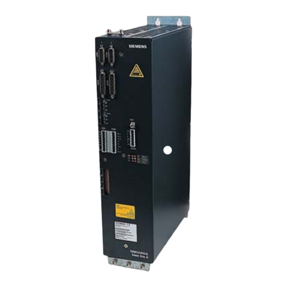
● Power module ● Fig.1-1 SIMODRIVE base line A (1-axis/2-axes module, V1/V2) SIMODRIVE base line A SIMODRIVE base line A can be ordered with the following two versions: versions: V1: 1-axis version, motor static torque of 6Nm, 11Nm, 8Nm, 16Nm;... - Page 8 SIMODRIVE base line A. The major difference between SIMODRIVE base line A and SIMODRIVE baseline is that SIMODRIVE base line A is used with an adjustable combination of 1FK7 servo motors with 4-pole pairs resolver encoder, while the SIMODRIVE base line is used with a fixed combination of 1FK7 servo motors with 1-pole pair resolver encoder.
-
Page 9: Technical Data
Power derating in 1000m,Max. 2000m; range 1000m ~2000m sea level Atmospheric Min. 860 mbar (86kPa); pressure Max. 1080 mbar (108kPa) Applicable DIN IEC 68-2-1 standards DIN IEC 68-2-2 DIN IEC 68-2-3 DIN VDE0160 5.2.1.3 EN50178 SIMODRIVE base line A Start-Up... - Page 10 For other days (<24h): U=85%;t =24°C; but it should accord with the annual average Applicable DIN IEC 68-2-1 standards DIN IEC 68-2-2 DIN IEC 68-2-3 DIN VDE0160 5.2.1.3 EN50178 Protection class IP20 according to DIN EN 60529. SIMODRIVE base line A Start-Up...
-
Page 11: Order Number
Introduction 1.3. Order number General SIMODRIVE base line A is delivered in 2 basic versions. They are adapted to the machine tools with 1-axis and 2-axes control respectively. Other versions of configurations are also available on customer’s request. Moreover, the accessories and cables should be ordered separately by the customers. -
Page 13: Installation
5. The protective grounding cable should be connected properly. Mounting location SIMODRIVE base line A is of a compact design, so that the installation is very simple. When fixing the servo drive in the cabinet, four (4) M6 screws are required. - Page 14 Installation Mounting The mounting dimensions are shown in the following figures. dimensions 1) Clearance space for sufficient cooling Fig. 2-1 Mounting dimensions SIMODRIVE base line A Start-Up...
- Page 15 Installation 2-axes module 1-axis module Fig.2-2 Mounting dimensions (continued) SIMODRIVE base line A Start-Up...
-
Page 16: Installation Of Accessories
The shielded plate has clamp connections and mounting points for brake terminals. For the installation of shielded plate into SIMODRIVE base line A, please refer to section 2.7 “Power supply – shielded plate”. -
Page 17: Commissioning Of Simodrive Base Line A
Installation 2.3. Commissioning of SIMODRIVE base line A General In order to optimize the dynamic performance of the servo drive, the commissioning is to be carried out as follows: Main switch: Open Adapt DIL switch S1/S2 to the motor by setting the switch to the standard... - Page 18 K integral action time T through corresponding potentiometers to obtain an optimal result. Rotating clockwise increases the controller dynamic performance. Optimization: 20...40% approx.0.05*n rated =5...10ms Fig.2-3 Optimized controller dynamic performance curve SIMODRIVE base line A Start-Up...
-
Page 19: Interfaces And Cabling
Speed setpoint & controller enable interface X321+X322(2-axes)/X321(1-axis) DIL switch S1+S2(2-axes)/S1(1-axis) Grounding terminal X131 Enable interface terminal X141A LED lights PE1/PE2/PE A1(U2,V2,W2)/A2(U2,V2,W2) X1(U1,V1,W1) Fig.2-4 Front panel of SIMODRIVE base line A (2-axes module left, 1-axis module right) SIMODRIVE base line A Start-Up... - Page 20 X141A - enable interface terminal ● Terminal 63 is the pulse enable input; Terminal 9 is the enable output; Terminal 64 is the drive enable input; R is the reset interface; Terminal 19 is the basis grounding. SIMODRIVE base line A Start-Up...
- Page 21 Three-phase 400/415VAC line power feeder. LED lights There are six LEDs on the front panel to indicate the current status of each circuit in SIMODRIVE base line A. Their meanings are as follows: - +/- 15V electronical level fault Spp (red) ●...
-
Page 22: Cable Connection
Installation 2.5. Cable connection General As a standard configuration of SIMODRIVE base line A, SINUMERIK 802 C base line is applied together with SIEMENS servomotors (1FK7) in CNC Turning/Milling machine. The components are wired up as shown in the connection diagram Fig. 2-5. The required cable for the connection between NC, drive and motors is also indicated in the figure. -
Page 23: Interface Description
Controller enable, axis 2 65.1 65.2 DIL switch settings: DIL switch (current controller setting, axis 1 ) DIL switch (current controller setting, axis 2) Ready/fault signal Fig. 2-6 Interface overview of control module (2-axes) SIMODRIVE base line A Start-Up 2-11... -
Page 24: Pole Pair Numbers
DIL switch: S1 - used for selection of servomotors controlled by 1-axis module; S2 – used for selection of servomotors controlled by 2-axes module; Table 2-2 Adaptation table for Simodrive base line A (1-axis module) (I) Curr. act. value norm. -
Page 25: Position Feedback Interface - X391/X392
Connector designation: Encoder connector servomotor side Connector type: 12 –pin aero-connector, socket Table 2-5 Pin assignment of the connector X311/X312 Signal Servodrive side Servomotor side SIN_PLUS SIN_MINUS 5,8,24 COS_PLUS COS_MINUS RES_POS RES_NEG TEMP_PLUS TEMP_MINUS SIMODRIVE base line A Start-Up 2-13... -
Page 26: Drift Compensation - Drift Potentiometer
When the speed setpoint is reduced, the setting range is also appropriately reduced. We recommend that the motors with a rated speed of 2250 RPM are operated using a ± 9V speed setpoint, in order to limit the selectable maximum speed. 2-14 SIMODRIVE base line A Start-Up... -
Page 27: Proportional Gain - K
K potentiometer 2.6.1.8. Integral action time - T potentiometer General The speed controller integral action time is set using T potentiometer. Setting T potentionmeter Fig. 2-9 Setting integral action time using T potentiometer SIMODRIVE base line A Start-Up 2-15... - Page 28 X321/322 Reference potential X321/322 Reference potential X321/322 Active current 0…±10 actual value X321/322 Enable potential X321/322 Controller +13…30 enable, axis1 1) X321 for axis 1, X322 for axis 2 2) I =Input, O =Output 2-16 SIMODRIVE base line A Start-Up...
- Page 29 2.7. Power supply General SIMODRIVE base line A can be connected directly to TN line supplies. For all other line supply types, an isolating transformer with grounded neutral point on the secondary side must be used. The figure 2-9 shows how to connect the drive converter to line supply.
-
Page 30: Infeed Module Interface
1) Terminal 19 is the reference terminal (this is connected inside the module to general reference ground X131 with 10 kΩ) 2) Max. current load, terminal 9 –terminal 19: 1A 3) I = Input, O = Output SIMODRIVE base line A Start-Up 2-17... - Page 31 TT system: it is symmetrical 3-conductor or 4-conductor three-phase ● network with a directly grounded point, the loads are, e.g., connected to groundings which are not electrically connected to the directly grounded point of the network. SIMODRIVE base line A Start-Up 2-19...
- Page 32 Installation Fig. 2-11 Three types of line supply systems 2-20 SIMODRIVE base line A Start-Up...
- Page 33 16AD01 Neoz./B.No.5SE2116; Or you can choose SIEMENS circuit breaker: 3RV1031-4BA10. Isolating SIMODRIVE base line A can be connected directly to TN-C line supply transformer system. The isolating transformer is used as an option in this line supply type. The connecting diagram is shown in the Fig.2-10. But the isolating transformer must be used in following cases: IT line supply system or TT line supply system;...
- Page 34 Input current <10% without load Vector degree Y/Y0 Max. coil temp. <80 boost Remarks: * It is valid for the tailored transformers, which is to be observed by the customer when purchasing. 2-22 SIMODRIVE base line A Start-Up...
- Page 35 Installation Table 2-9 Technical specifications (SIEMENS matching transformer) Designation Parameter Unit Rated power Output voltage 400,3-pahase AC Frequency 50-5% to 60+5% Rated input 12.5 current Degree of IP00,IP20 and IP23 to DIN EN 60529 protection Humidity 3K5, condensation and icing excluded classification °C...
- Page 36 The commutating reactor is already integrated in the infeed module in SIMODRIVE base line A. It is not required for customer to install another commutating reactor. Shielded plate In order to meet the requirements of the EC Directive on EMC, the motor cable should be shielded.
- Page 37 Note: When cable grounding, the tongue of hoop must be separated from the cable and located at each side of shield plate, so as to prevent damaging the cable. Fig.2-13 Mounting shielded plate Fig.2-14 Connection of brake terminal SIMODRIVE base line A Start-Up 2-25...
-
Page 38: Grounding
The grounding terminal X131 is to be connected separately with the protective conductor in NC. X312 X392 X311 X391 X131 SIMODRIVE base line A L1L2 L3 PE Fig. 2-15 Grounding diagram for SIMODRIVE base line A (2-axes) 2-26 SIMODRIVE base line A Start-Up... -
Page 39: Technical Description
Control process Power Speed Current section Coordinator Resolver controller controller servomotor Gating unit Rotor position Actual current Current measurements Actual speed Motor encoder measurements Fig.3-1 Control process in SIMODRIVE base line A SIMODRIVE base line A Start-Up... -
Page 40: Infeed Module
3.2. Infeed module General SIMODRIVE base line A is connected to the power supply via the infeed modules. The infeed module generates the DC voltage 600V from the line supply. And the PWM DC link voltage is provided for the stator windings in the motor. - Page 41 2.Terminal 64 is inhibited.Speed setpoint is set to 0 for all drives and the drives are braked.After the set timers have expired (as supplied:240ms),all of the controllers and pulses are inhibited.The drives brake along the current limit. Fig.3-3 Enable signal in infeed module SIMODRIVE base line A Start-Up...
-
Page 42: Control Module
The dynamic response in low velocity is improved through speed-controller- adaption. The speed controller is to be optimized through varying integral time and proportional gain. Control process Refer to Fig. 3-4 for the control process. SIMODRIVE base line A Start-Up... - Page 43 Technical description Fig 3-4 Block diagram of control module SIMODRIVE base line A Start-Up...
- Page 44 And the axes are stopped. Motor overtemperature SIMODRIVE base line A feed modules with closed-loop control for ● servomotors are equipped with an evaluation circuit for the PTC thermistors integrated in the motor windings. The monitoring combination is intended to protect the motors against inadmissible high winding temperatures (trip temperature 150°C).
-
Page 45: Servomotor
A. 1FK7 AC servomotors are extremely compacted permanent-magnetic synchronous motors. Together with the SIMODRIVE base line A, the 1FK7 motors are powerful system with high functionality. The built-in resolver system is used to control the speed and position. - Page 46 3000 5AF71-1S□0 Note: without brake It’s recommended that the speed of the servomotor configured for SIMODRIVE base line A is set as 2250rpm. This servomotor shall be derated when complete temperature rise of windings ∆T=100K. SIMODRIVE base line A Start-Up...
- Page 47 DC link motor 1FK7060 - 5AF71 S3 - 25% S3 - 40% S3 - 60% S1 (100K) S1 (60K) 1000 1500 2000 2500 3000 3500 Speed [min-1] Fig. 4-2 Motor speed – torque diagram 1FK7060-5AF71-1 S□0 SIMODRIVE base line A Start-Up...
- Page 48 Fig. 4-3 Motor speed – torque diagram 1FK7063-5AF71-1S□0 1FK7080 - 5AF71 S3 - 25% S3 - 40% S3 - 60% S1 (100K) S1 (60K) 1000 1500 2000 2500 3000 3500 Speed [min-1] Fig. 4-4 Motor speed – torque diagram 1FK7080-5AF71-1S□0 SIMODRIVE base line A Start-Up...
- Page 49 Please refer to Fig.4-1 and Table 4-3 for the mounting dimensions of the servomotor. Fig.4-6 Motor size Table 4-3 Motor dimensions Order No. 1FK7042- 5AF71-1S□0 1FK7060- 5AF71-1S□0 1FK7063- 5AF71-1S□0 1FK7080- 119.5 77.5 5AF71-1S□0 1FK7083- 119.5 77.5 5AF71-1S□0 SIMODRIVE base line A Start-Up...
- Page 50 Servomotor Table 4-3 Motor dimensions (con’d) Without brake With brake Order No. 1FK7042- 21.5 5AF71-1S□0 1FK7060- 5AF71-1S□0 1FK7063- 5AF71-1S□0 1FK7080- 5AF71-1S□0 1FK7083- 5AF71-1S□0 SIMODRIVE base line A Start-Up...
- Page 51 SIEMENS NUMERICAL CONTROL Suggestions LTD.,NANJING,CHINA Corrections For publication/Manual: R&D Division No.18,Siemens Road, Jiangning Development Zone SIMODRIVE base line A 211100 NANJING Start-Up People’s Republic of China Zip code: 211100 Manufacturer Documentation Telephone: 025-52101888 Fax: 025-52101666 From Technical manual Name 6SN1197-0AB21-0BP1...
- Page 52 SIMODRIVE base line A Document structure General Documentation: Catalog SINUMERIK 802S Leaflet Technical Manual: Start-Up SINUMERIK 802S Start-up...
Need help?
Do you have a question about the SIMODRIVE base line A and is the answer not in the manual?
Questions and answers