Table of Contents
Advertisement
Quick Links
Industrial Automation Headquarters
Delta Electronics, Inc.
Taoyuan Technology Center
No.18, Xinglong Rd., Taoyuan District,
Taoyuan City 33068, Taiwan
TEL: 886-3-362-6301 / FAX: 886-3-371-6301
Asia
Delta Electronics (Shanghai) Co., Ltd.
No.182 Minyu Rd., Pudong Shanghai, P.R.C.
Post code : 201209
TEL: 86-21-6872-3988 / FAX: 86-21-6872-3996
Customer Service: 400-820-9595
Delta Electronics (Japan), Inc.
Tokyo Office
Industrial Automation Sales Department
2-1-14 Shibadaimon, Minato-ku
Tokyo, Japan 105-0012
TEL: 81-3-5733-1155 / FAX: 81-3-5733-1255
Delta Electronics (Korea), Inc.
Seoul Office
1511, 219, Gasan Digital 1-Ro., Geumcheon-gu,
Seoul, 08501 South Korea
TEL: 82-2-515-5305 / FAX: 82-2-515-5302
Delta Energy Systems (Singapore) Pte Ltd.
4 Kaki Bukit Avenue 1, #05-04, Singapore 417939
TEL: 65-6747-5155 / FAX: 65-6744-9228
Delta Electronics (India) Pvt. Ltd.
Plot No.43, Sector 35, HSIIDC Gurgaon,
PIN 122001, Haryana, India
TEL: 91-124-4874900 / FAX : 91-124-4874945
Delta Electronics (Thailand) PCL.
909 Soi 9, Moo 4, Bangpoo Industrial Estate (E.P.Z),
Pattana 1 Rd., T.Phraksa, A.Muang,
Samutprakarn 10280, Thailand
TEL: 66-2709-2800 / FAX : 662-709-2827
Delta Electronics (Australia) Pty Ltd.
Unit 20-21/45 Normanby Rd., Notting Hill Vic 3168, Australia
TEL: 61-3-9543-3720
Americas
Delta Electronics (Americas) Ltd.
Raleigh Office
P.O. Box 12173, 5101 Davis Drive,
Research Triangle Park, NC 27709, U.S.A.
TEL: 1-919-767-3813 / FAX: 1-919-767-3969
Delta Electronics Brazil
São Paulo Sales Office
Rua Itapeva, 26 - 3°, andar Edificio Itapeva,
One - Bela Vista 01332-000 - São Paulo - SP - Brazil
TEL: 55-12-3932-2300 / FAX: 55-12-3932-237
Delta Electronics International Mexico S.A. de C.V.
Mexico Office
Gustavo Baz No. 309 Edificio E PB 103
Colonia La Loma, CP 54060
Tlalnepantla, Estado de México
TEL: 52-55-3603-9200
*We reserve the right to change the information in this user manual without prior notice.
DELTA_IA-MDS_IED-S_UM_EN_20210303
EMEA
Headquarters:
Delta Electronics (Netherlands) B.V.
Sales: Sales.IA.EMEA@deltaww.com
Marketing: Marketing.IA.EMEA@deltaww.com
Technical Support: iatechnicalsupport@deltaww.com
Customer Support: Customer-Support@deltaww.com
Service: Service.IA.emea@deltaww.com
TEL: +31(0)40 800 3900
BENELUX:
Delta Electronics (Netherlands) B.V.
De Witbogt 20, 5652 AG Eindhoven, The Netherlands
Mail: Sales.IA.Benelux@deltaww.com
TEL: +31(0)40 800 3900
DACH:
Delta Electronics (Netherlands) B.V.
Coesterweg 45, D-59494 Soest, Germany
Mail: Sales.IA.DACH@deltaww.com
TEL: +49(0)2921 987 0
France:
Delta Electronics (France) S.A.
ZI du bois Challand 2, 15 rue des Pyrénées,
Lisses, 91090 Evry Cedex, France
Mail: Sales.IA.FR@deltaww.com
TEL: +33(0)1 69 77 82 60
Iberia:
Delta Electronics Solutions (Spain) S.L.U
Ctra. De Villaverde a Vallecas, 265 1º Dcha Ed.
Hormigueras – P.I. de Vallecas 28031 Madrid
TEL: +34(0)91 223 74 20
Carrer Llacuna 166, 08018 Barcelona, Spain
Mail: Sales.IA.Iberia@deltaww.com
Italy:
Delta Electronics (Italy) S.r.l.
Via Meda 2–22060 Novedrate(CO)
Piazza Grazioli 18 00186 Roma Italy
Mail: Sales.IA.Italy@deltaww.com
TEL: +39 039 8900365
Russia:
Delta Energy System LLC
Vereyskaya Plaza II, office 112 Vereyskaya str.
17 121357 Moscow Russia
Mail: Sales.IA.RU@deltaww.com
TEL: +7 495 644 3240
Turkey:
Delta Greentech Elektronik San. Ltd. Sti. (Turkey)
Şerifali Mah. Hendem Cad. Kule Sok. No:16-A
34775 Ümraniye – İstanbul
Mail: Sales.IA.Turkey@deltaww.com
TEL: + 90 216 499 9910
GCC:
Delta Energy Systems AG (Dubai BR)
P.O. Box 185668, Gate 7, 3rd Floor, Hamarain Centre
Dubai, United Arab Emirates
Mail: Sales.IA.MEA@deltaww.com
TEL: +971(0)4 2690148
Egypt + North Africa:
Delta Electronics
Unit 318, 3rd Floor, Trivium Business Complex, North 90 street,
New Cairo, Cairo, Egypt
Mail: Sales.IA.MEA@deltaww.com
Delta Integrated
Elevator Drive
IED-S Series
User Manual
w w w. d e l t a w w. c o m
Advertisement
Table of Contents

Related Manuals for Delta IED-S Series


Summary of Contents for Delta IED-S Series
- Page 1 TEL: +7 495 644 3240 Raleigh Office P.O. Box 12173, 5101 Davis Drive, Turkey: Delta Greentech Elektronik San. Ltd. Sti. (Turkey) Research Triangle Park, NC 27709, U.S.A. Şerifali Mah. Hendem Cad. Kule Sok. No:16-A TEL: 1-919-767-3813 / FAX: 1-919-767-3969 34775 Ümraniye – İstanbul Mail: Sales.IA.Turkey@deltaww.com...
- Page 2 Limitation of Liability The contents of this user manual are only for the use of the AC motor drives manufactured by Delta. Except as defined in special mandatory laws, Delta provides this user manual “as is” and does not offer any kind of warranty through this user manual for using the product, either express or implied, including but not limited to the following: (i) this product will meet your needs or expectations;...
- Page 4 PLEASE READ PRIOR TO INSTALLATION FOR SAFETY. Disconnect power before connecting any wiring to IED-S. Even if the power has been turned off, a charge may still remain in the DC-link capacitors with hazardous voltages before the POWER LED is OFF. Do NOT touch the internal circuits and components.
-
Page 5: Table Of Contents
Table of Contents CHAPTER 1 INTRODUCTION ........................1-1 1-1 Nameplate Information…………....................1-2 1-2 Model Name…………........................1-3 1-3 Serial Number..........................1-3 1-4 Apply After Service by Mobile Device…………………………..……………………………...…….1-4 1-5 RFI Switch…..........................1-7 1-6 Dimensions...........................1-10 CHAPTER 2 INSTALLATION ........................2-1 2-1 Mounting Clearance........................2-2 2-2 Airflow and Power Dissipation......................2-3 2-3 Derating Curve for Ambient Temperature, Altitude and Carrier Frequency........2-4 CHAPTER 3 WIRING .......................... - Page 6 CHAPTER 8 SPECIFICATIONS ....................... 8-1 8-1 230V Series………………………………………................8-2 8-2 460V Series………………………….……………................8-2 8-3 General Specifications……..……………………................8-3 8-4 Operation, Storage and Transportation Environments…..………..………………….....8-4 CHAPTER 9 DIGITAL KEYPAD ....................... 9-1 9-1 Description of Keyboard Panel …………………………….…………..........9-2 9-2 Description of the Digital Keypad KPC-CC01 ................9-5 9-3 Digital Keypad KPC-CC01 Functions...................9-7 9-4 Digital Keypad KPC-CC01 Fault and Warning Codes and Descriptions………...….……………9-17 CHAPTER 10 AUTO-TUNING PROCESS ....................
- Page 7 CHAPTER 15 IED-S SAFE TORQUE OFF FUNCTION…………………………………………………….15-1 15-1 Failure Rate of IED-S’ Safety Function…….…………………...……..……………………………15-2 15-2 Circuit Diagram…………………….………………………………………………………………….15-3 APPENDIX A. Single-phase Application………...……………..…………………………………………….A-1 A.1 Introduction to the Application of Drives and Single-phase Power System…….…………………A-1 A.2 Key Points to Consider when Using the Three-phase Drive for Single-phase Power Input…..…A-2 A.3 Input Frequency and Voltage Tolerance………………………..…………………………………….A-3 APPENDIX B.
-
Page 8: Chapter 1 Introduction
Chapter 1 Introduction | IED-S Chapter 1 Introduction Nameplate Information Model Name Serial Number Apply After Service by Mobile Device RFI Switch Dimensions... -
Page 9: Nameplate Information
Chapter 1 Introduction | IED-S After you receive the AC motor drive, check the following: 1. Inspect the unit after unpacking to ensure that it was not damaged during shipment. Make sure that the part number printed on the package corresponds with the part number indicated on the nameplate. -
Page 10: Model Name
Chapter 1 Introduction | IED-S 1-2 Model Name 1-3 Serial Number... -
Page 11: Apply After Service By Mobile Device
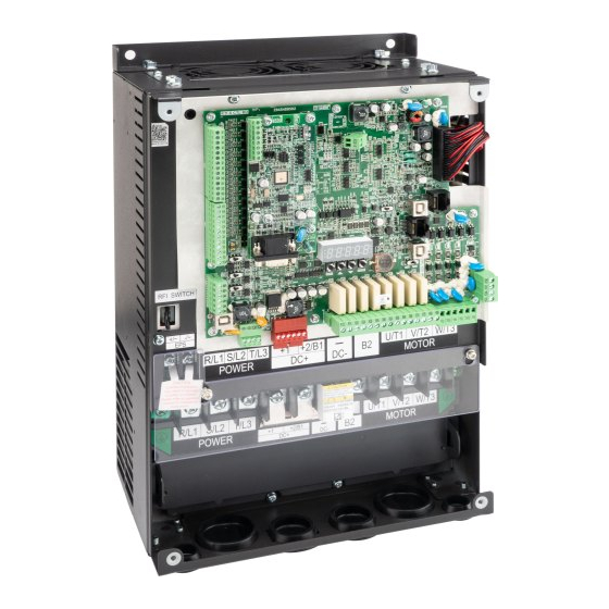
Chapter 1 Introduction | IED-S 1-4 Apply After Service by Mobile Device 1-4-1 Location of Service Link Label Frame C The service link label (service label) is located at the right side of the drive, as the image below shows. Frame D The service link label (service label) is located on the upper left corner at the front side of the drive, as the image below shows. - Page 12 Chapter 1 Introduction | IED-S Frame E The service link label (service label) is located on the upper left corner at the front side of the drive, as the image below shows.
- Page 13 2. Run the QR code reader App on your smartphone. 3. Point your camera at the QR Code. Hold your camera steady until the QR code comes into focus. 4. Access the Delta After-Sales Service website. 5. Fill in the information in the columns marked with an orange star.
-
Page 14: Rfi Switch
Chapter 1 Introduction | IED-S 1-5 RFI Switch The AC motor drive may emit electrical noise. You can use the RFI (Radio Frequency Interference) switch to suppress interference on the power line. The RFI switches on Frames C, D, and E are at similar locations. - Page 15 Chapter 1 Introduction | IED-S Isolating main power from ground When the power distribution system for the motor drive is a floating ground system (IT) or an asymmetric ground system (TN), you must remove the RFI switch. Removing the switch also cuts off the internal RFI capacitor (filter capacitor) between the system's frame and the central circuits to avoid damaging the central circuits and reduces the ground leakage current.
- Page 16 Chapter 1 Introduction | IED-S Asymmetric Ground System (Corner Grounded TN Systems) Caution: Do not remove the RFI switch while power to the motor drive input terminal is ON. In the following four situations, you must remove the RFI switch. This is to prevent the system from grounding through the RFI capacitor and damaging the motor drive.
-
Page 17: Dimensions
Chapter 1 Introduction | IED-S 1-6 Dimensions Frame C IED022S21A; IED037S21A; IED055S23A; IED075S23A; IED110S23A; IED055S43A; IED075S43A; IED110S43A; IED150S43A; IED185S43A Unit: mm [inch] Frame 235.0 204.0 176.0 350.0 339.0 337.0 146.0 [9.25] [8.03] [6.93] [13.78] [13.35] [13.27] [5.76] [0.26] [0.35] [0.28] NOTE: A1–A4 and B1–B4 can be used for screwdriver installation;... - Page 18 Chapter 1 Introduction | IED-S Frame D IED150S23A; IED185S23A; IED220S23A; IED220S43A; IED300S43A Unit: mm [inch] Frame 255.0 226.0 403.8 384.0 178.0 [10.04] [8.90] [15.90] [15.12] [7.01] [0.33] 1-11...
- Page 19 Chapter 1 Introduction | IED-S Frame E IED370S43A; IED450S43A; IED550S43A; IED750S43A Unit: mm [inch] Frame 16.0 11.0 18.0 330.0 285.0 550.0 525.0 308.9 [12.99] [11.22] [21.65] [20.67] [12.16] [0.63] [0.43] [0.71] 1-12...
-
Page 20: Chapter 2 Installation
Chapter 2 Installation | IED-S Chapter 2 Installation 2-1 Mounting Clearance 2-2 Airflow and Power Dissipation 2-3 Derating Curve for Ambient Temperature, Altitude, and Carrier Frequency... - Page 21 Chapter 2 Installation | IED-S 2-1 Mounting Clearance Do not allow material such as fiber particles, scraps of paper, shredded wood, sawdust, and metal particles to adhere to the heat sink. Install the AC motor drive in a metal cabinet to prevent the risk of fire. ...
- Page 22 Chapter 2 Installation | IED-S 2-2 Airflow and Power Dissipation Power Dissipation for Airflow Rate for Cooling AC Motor Drive Flow Rate [cfm] Flow Rate [m /hr] Power Dissipation [W] Model No. Loss External External Internal Total External Internal Total Internal Total (Heat Sink)
-
Page 23: Derating Curve For Ambient Temperature, Altitude And Carrier Frequency
Chapter 2 Installation | IED-S 2-3 Derating Curve for Ambient Temperature, Altitude and Carrier Frequency Carrier Frequency (Fc) Derating Capacity Frame Fc (kHz) 2.2–4 kW 5.5–11 kW 15–22 kW 30–45 kW 55–75kW 100% 100% 100% 100% 100% 100% 100% 100% 100% 100% 100%... - Page 24 Chapter 2 Installation | IED-S Ambient Temperature Derating Curve Altitude Derating Curve...
- Page 25 Chapter 2 Installation | IED-S [The page intentionally left blank]...
-
Page 26: Chapter 3 Wiring
Chapter 3 Wiring | IED-S Chapter 3 Wiring 3-1 System Wiring Diagram 3-2 Wiring 3-3 Related Wiring Diagrams 3-4 Code Reference Table... - Page 27 Chapter 3 Wiring | IED-S After removing the front cover, verify that the power and control terminals are clear. Be sure to observe the following precautions when wiring. Make sure that power is only applied to the R/L1, S/L2, and T/L3 terminals. Failure to comply may result in damage to the equipment.
- Page 28 Chapter 3 Wiring | IED-S 3-1 System Wiring Diagram Supply power according to the rated power Power input specifications indicated in the manual (see Chapter 08 Specifications). There may be a large inrush current during power on. See Section 6-2 NFB to select a fuse suitable NFB or fuse.
- Page 29 Chapter 3 Wiring | IED-S IED-S (Integrated Elevator Drive) System Wiring Diagram 01 System Configuration...
- Page 30 Chapter 3 Wiring | IED-S 02 Wiring Diagram for Group Control Example of Group Control … … IED-S 1 IED-S 2 IED-S 3 IED-S 4 [Main] Pr.03-03 Elevator No.: 0 Pr.03-04 = 4...
-
Page 31: Wiring
Chapter 3 Wiring | IED-S 3-2 Wiring * See Figure 2 on page 3-8 for the Emergency Power Supply (EPS) system wiring diagrams. : See Section 6-1 Brake Resistors & Brake Units Used in AC Motor Drives for details. - Page 32 Chapter 3 Wiring | IED-S...
- Page 33 Chapter 3 Wiring | IED-S Figure 1 SOURCE (PNP) Terminal Figure 2 Emergency Power Supply (EPS) system wiring diagrams Frames C, D and E Single-phase UPS or battery can only be used on the main power supply side Frames C and D When the voltage of the main power supply is lower than 140 V (230V series) / 280 V (460V...
- Page 34 Chapter 3 Wiring | IED-S Notes on Emergency Power Supply (EPS): 1. When EPS is enabled, do NOT make the fan run in order to prevent voltage drop during EPS. 2. When EPS is enabled, parameter settings cannot be saved and will be lost after cycling power. 3.
-
Page 35: Related Wiring Diagrams
Chapter 3 Wiring | IED-S 3-3 Related Wiring Diagrams 03 Main Circuit for Drive Control (Synchronous) 3-10... - Page 36 Chapter 3 Wiring | IED-S 04 Main Circuit for Drive Control (Asynchronous) 3-11...
- Page 37 Chapter 3 Wiring | IED-S 05 Control Power Configuration Current for DC24V power supply (normally ≥ 4.5 A / DC24 V; 2.5 A / AC110 V) Current = 1.5 + (X + 2Y) x Z + N x Y X: Rated current of one piece of hall call board Y: Current of one button Z: A few pieces of common hall call boards N: A few common car buttons...
- Page 38 Chapter 3 Wiring | IED-S 06 Safety Hatch 3-13...
- Page 39 Chapter 3 Wiring | IED-S 07 Brake Circuit 3-14...
- Page 40 Chapter 3 Wiring | IED-S 08 Inspection Circuit (Cartop Inspection Connected to IED-S Control Board) 3-15...
- Page 41 Chapter 3 Wiring | IED-S 09 Inspection Circuit (Cartop Inspection Connected to Cartop Board) (without Using Traveling Cable) 3-16...
- Page 42 Chapter 3 Wiring | IED-S 10 Input Contacts of Main Control Board for the Control Panel 3-17...
- Page 43 Chapter 3 Wiring | IED-S 11 Output Contacts of Main Control Board for the Control Panel 3-18...
- Page 44 Chapter 3 Wiring | IED-S 12 Contacts of Cartop Board (OCB) 3-19...
- Page 45 Chapter 3 Wiring | IED-S 13 Maneuvering Box 1–16 Floor (ICB) 3-20...
- Page 46 Chapter 3 Wiring | IED-S 14-1 Hall Call System 3-21...
- Page 47 Chapter 3 Wiring | IED-S 14-2 Hall Call Board Connected to Normal Call, Elevator Lock (Shutdown), and Fire Alarm Recall Hall call function settings: 1. Switch SW2 to SET to start the settings. 2. Press DOWN when the floor position displays 0. Press DOWN again to change the mode selection of the arrow position.
- Page 48 Chapter 3 Wiring | IED-S 14-3 Hall Call Board Connected to Normal Call and Disability Call Station Number Setting 1–64 Disability Front Door ● 1–64 Disability Rear Door ● 3-23...
- Page 49 Chapter 3 Wiring | IED-S 14-4 Hall Call Board Connected to Directional Lantern and Directional Chime Station Number Setting Front Door 1–64 Directional Lantern and Directional Chime ●● Rear Door 1–64 Directional Lantern and Directional Chime ●● Note: The output load for the hall call board must be smaller than 250 mA. Otherwise, install an extra relay to control.
- Page 50 Chapter 3 Wiring | IED-S 15 Lighting Circuit 3-25...
- Page 51 Chapter 3 Wiring | IED-S 16 UCMP Board (Three Sensors: DZU, FL1, and DZD) 3-26...
- Page 52 Chapter 3 Wiring | IED-S 17 UCMP Board (Four Sensors: DZU, FL1, FL2, and DZD) 3-27...
- Page 53 Chapter 3 Wiring | IED-S 18 Governor Operation Circuit without Machine Room Solution 1: Governor coil voltage is AC110V Solution 2: Governor coil voltage is DC24V 3-28...
- Page 54 Chapter 3 Wiring | IED-S 19 Cable Table Traveling Cable (for Cartop Inspection in Series) Front Layer Door Safety Hatch Switch Front layer door safety hatch switch at first floor Car outlet, lighting, fan power Front layer door safety hatch switch at top floor Door controller power Rear Layer Door Safety Hatch Switch...
-
Page 55: Code Reference Table
Chapter 3 Wiring | IED-S 3-4 Code Reference Table Code Description Landing hall operation panel Hall call (landing hall call) circuit board Car operation panel Car command board Cartop board Contactor between the drive and motor (operation contactor) Relay that controls the Safe Torque Off (STO) of the drive Brake resistor Transformer that changes from ACXXXV to AC110V, used for control... - Page 56 Chapter 3 Wiring | IED-S Code Description N. C. (Normally Closed) contact of layer door safety (DS) hatch DSNC contactor TCIN Traveling cable insertion SWNC N.C. contact of operation contactor (SW) BY1NC N.C. contact of Brake-1 contactor (BY1) BY2NC N.C. contact of Brake-2 contactor (BY2) BY3NC N.C.
- Page 57 Chapter 3 Wiring | IED-S Code Description Door unlock output feedback N.O. contact of MPSCC (Motor Phase Short Circuit Contactor) for FXNO OLT1 Front door reaches its open position OLT2 Rear door reaches its open position CLT1 Front door reaches its closed position CLT2 Rear door reaches its closed position EDP1...
- Page 58 Chapter 3 Wiring | IED-S Code Description Independent operation switch Goods only switch Attendant mode VIP mode CLIS Car lighting switch Car fan switch DCB2 Door close button (rear door) DOB2 Door open button (rear door) DOBH2 Door open extended button (rear door) ERGO Safety landing while severe earthquake Peak running at random floor...
- Page 59 Chapter 3 Wiring | IED-S Code Description LPTD Downward floor arrival clock FCL1 Front door forced close at low speed FCL2 Rear door forced close at low speed S2XX0 Voice announces the floor arrives S2XX1 Voice announces the floor arrives S2XX2 Voice announces the floor arrives S2XX3...
-
Page 60: Chapter 4 Main Circuit Terminals
Chapter 4 Main Circuit Terminals | IED-S Chapter 4 Main Circuit Terminals 4-1 Main Circuit Diagram 4-2 Main Circuit Terminal Specifications... - Page 61 Chapter 4 Main Circuit Terminals | IED-S Main input power terminals Do NOT connect a three-phase model to single-phase power. R/L1, S/L2 and T/L3 have no phase-sequence requirement and can be connected in any sequence. You must install a NFB between the three-phase power input terminals and the main circuit terminals (R/L1, S/L2, T/L3).
-
Page 62: Main Circuit Diagram
Chapter 4 Main Circuit Terminals | IED-S 4-1 Main Circuit Diagram Frame C and D Frame E Terminal Symbol Description Emergency power or backup power connection terminal EPS (+, -) NOTE: EPS (Emergency Power Supply) input terminal supports only frames C & D. R/L1, S/L2, T/L3 Commercial power input terminal AC motor drive output terminals for connection a three-phase induction... -
Page 63: Main Circuit Terminal Specifications
Chapter 4 Main Circuit Terminals | IED-S 4-2 Main Circuit Terminal Specifications Frame C Frame C Main circuit terminals: R/L1, S/L2, T/L3, U/T1, V/T2, W/T3, +1, Ground terminal: +2/B1, -, B2 Model Max. Min. Screw Size Max. Min. Screw Size Wire Wire and Tightening... - Page 64 Chapter 4 Main Circuit Terminals | IED-S Frame D Frame D Main circuit terminals: R/L1, S/L2, T/L3, U/T1, V/T2, W/T3, +1, Ground terminal: +2/B1, -, B2 Model Max. Min. Screw Size Max. Min. Screw Size Wire Wire and Tightening Wire Wire and Tightening Gauge...
- Page 65 Chapter 4 Main Circuit Terminals | IED-S Frame E Frame E Main circuit terminals: R/L1, S/L2, T/L3, U/T1, V/T2, W/T3, +1(DC+), Ground terminal: -(DC-) Model Screw Screw Max. Min. Size and Min. Size and Max. Wire Wire Wire Tightening Wire Tightening Gauge Gauge...
-
Page 66: Control Terminal Specifications
Chapter 5 Control Terminals | IED-S Chapter 5 Control Terminals 5-1 Control Terminal Specifications... - Page 67 Chapter 5 Control Terminals | IED-S 5-1 Control Terminal Specifications...
- Page 68 Chapter 5 Control Terminals | IED-S 5-1-1 Control Circuit Terminals Terminal Socket Wire Gauge Torque TB1/TB2/TB3/ 0.13–1.5 mm² [26–16 AWG] 2 kg-cm [1.74 lb-in.] (0.20 Nm) TB4/TB5/TB8 TB6/TB7/TB9 0.13–2.5 mm² [26–14 AWG] 4.9 kg-cm [4.25 lb-in.] (0.50 Nm) For UL installation compliance, use copper wires with rated voltage of 600 V and temperature resistance of 75°C or 90°C for wiring.
- Page 69 Chapter 5 Control Terminals | IED-S 5-1-2 Control Terminal Wiring Definition Terminal Terminal Default Setting Description Socket User-defined function Upper leveling switch [DZU] Non-isolated photocoupler input Door zone signal [SX1] Voltage > 19 V when terminal is guaranteed to Lower leveling switch [DZD] be activated (ON);...
- Page 70 Chapter 5 Control Terminals | IED-S Terminal Terminal Default Setting Description Socket +24V External power input +24 V +24V 24 V, 800 mA External power input 0 V Power cut-off safety function EN954-1 and STO (Safe Torque Off) IEC/EN61508 Range: -10–10 V Analog voltage input port User-defined function Analog control signal common...
- Page 71 Chapter 5 Control Terminals | IED-S Terminal Terminal Default Setting Description Socket PIN 1, 2, 6, 7: Reserved RJ45 PIN 3: SGND TB10 At the drive side PIN 4: SG- PIN 5: SG+ PIN 8: EV PIN 1, 2, 6, 7: Reserved RJ45 PIN 3: SGND TB11...
- Page 72 Chapter 5 Control Terminals | IED-S 5-1-3 LED Indicator Name Description Fault indicator Power indicator Regenerative indicator...
- Page 73 Chapter 5 Control Terminals | IED-S [The page intentionally left blank]...
-
Page 74: Chapter 6 Optional Accessories
Chapter 6 Optional Accessories | IED-S Chapter 6 Optional Accessories 6-1 Brake Resistors and Brake Units Used in AC Motor Drives 6-2 Non-fuse Circuit Breaker 6-3 Fuse Specification Chart 6-4 AC / DC Reactor 6-5 Zero Phase Reactor 6-6 EMC Filter 6-7 Digital Keypad... -
Page 75: Brake Resistors And Brake Units Used In Ac Motor Drives
The brake resistor should be able to endure 3.3 times the overload capacity. If you choose other brake resistors instead of Delta's, calculate the maximum power and average power of the selected braking power to ensure that they meet the requirements. Maximum power: Vb /R;... - Page 76 350°C, install extra cooling. If the resistor temperature is higher than the temperature limit, increase the size of the resistor.) The calculation of the braking current is based on Delta’s brake resistor and default braking voltage (220V 380V ;...
- Page 77 350°C, install extra cooling. If the resistor temperature is higher than the temperature limit, increase the size of the resistor.) The calculation of the braking current is based on Delta’s brake resistor and default braking voltage (220V 380V ;...
- Page 78 Chapter 6 Optional Accessories | IED-S NOTE Select the resistance value, power and brake usage (ED %) according to Delta rules. Definition for Brake Usage ED% For safety, install a thermal overload relay between the brake unit and the brake resistor in conjunction with the magnetic contactor (MC) at the drive mains input for additional protection.
- Page 79 Chapter 6 Optional Accessories | IED-S VFDB6055 / 6110 / 6160 / 6200 Braking Modules Instruction Sheet http://www.deltaww.com/filecenter/Products/download/06/060101/Option/DELTA_IA-MDS_VFDB6 055-6110-6160-6200_I_TSE_20121030.pdf The selection tables are for normal use. If the AC motor drive requires frequent braking, increase the Watts by two to three times. Thermal Overload Relay (TOR): Thermal overload relay selection is based on its overload capacity.
-
Page 80: Non-Fuse Circuit Breaker
Chapter 6 Optional Accessories | IED-S 6-2 Non-fuse Circuit Breaker Comply with the UL standard: Per UL 508, paragraph 45.8.4, part a. The rated current of a breaker shall be two to four times the maximum rated input current of the AC motor drive. Single-phase / Three-phase Three-phase Breaker Rated Input... -
Page 81: Ac / Dc Reactor
Chapter 6 Optional Accessories | IED-S 6-4 AC / DC Reactor AC Input Reactor Installing an AC reactor on the input side of an AC motor drive can increase line impedance, improve the power factor, reduce input current, increase system capacity, and reduce interference generated from the motor drive. - Page 82 28.4% Note THDi may vary due to different installation conditions and environment (wires, motors). THDi Specification Note: For three-phase power models, Delta provides 4% DC reactors and 3% AC reactors. Refer to the following sections to select your applicable reactors.
- Page 83 200V–230V / 50–60 Hz (Single-phase power) Rated Saturation AC Input AC Output AC Input Reactors AC Output Reactors Model Current Current Reactors Reactors (Delta Part#) (Delta Part #) (Arms) (Arms) (mH) (mH) IED022S21A 1.172 DR025D0117 2.02 DR012L0202 IED037S21A 0.574 DR049DP574 1.17...
- Page 84 Rated Saturation 3% AC Input / 3% AC Input / Output 4% DC 4% DC Reactors Model Current Current Output Reactors Reactors Reactors (Delta Part #) (Arms) (Arms) (mH) (Delta Part #) (mH) DR090AP141 IED185S23A 0.141 0.325 DR090DP325 DR090LP141 DR090AP141 IED220S23A 0.141...
- Page 85 Applicable Reactors (Compliance with EN12015) 200V–230V / 50–60 Hz (Three-phase power) Rated Saturation 5% AC Input 3% AC Input DC Reactors Model Current Current Reactors Reactors (Delta Part #) (Arms) (Arms) (mH) (Delta Part #) IED055S23A 0.898 IED075S23A 0.719 IED110S23A 0.479 IED150S23A 0.372...
- Page 86 Chapter 6 Optional Accessories | IED-S Reactor Dimensions AC input reactor dimension and specifications: PE MD Screw torque: F Nm Screw torque: 0.6–0.8 Nm Unit: mm Input Reactors D1*D2 PE D Delta Part # DR005A0254 DR008A0159 DR011A0115 6*12 80.5 DR017AP746 6*12 80.5 6-13...
- Page 87 Chapter 6 Optional Accessories | IED-S Installing screw: M5 PE MD Screw torque: F Nm Unit: mm Input Reactors D1*D2 PE D Delta Part # DR025AP215 6*12 80.5 DR033AP163 6*12 80.5 DR049AP163 6*12 6-14...
- Page 88 Chapter 6 Optional Accessories | IED-S Installing screw: M6 PE M6 Screw torque: 3 ± 1.5 Nm Unit: mm Input Reactors Delta Part # DR065AP162 See above. 6-15...
- Page 89 Chapter 6 Optional Accessories | IED-S Terminal gauge: 4 mm Screw torque: 0.8–1.0 Nm PE M8 x 23 Screw torque: 6 ± 0.3 Nm Unit: mm Input Reactors Delta Part # DR075AP170 See above. 6-16...
- Page 90 Chapter 6 Optional Accessories | IED-S Terminal gauge: 4 mm Screw torque: 0.8–1.0 Nm PE M8 x 23 Screw torque: 6 ± 0.3 Nm Unit: mm Input Reactors Delta Part # DR090AP141 See above. 6-17...
- Page 91 Chapter 6 Optional Accessories | IED-S Terminal gauge: 4 mm Screw torque: 0.8–1.0 Nm PE M8 x 23 Screw torque: 6 ± 0.3 Nm Unit: mm Input Reactors Delta Part # DR105AP106 See above. 6-18...
- Page 92 Chapter 6 Optional Accessories | IED-S Terminal gauge: 4 mm Screw torque: 0.6–0.8 Nm PE M8 x 23 Screw torque: 6 ± 0.3 Nm Unit: mm Input Reactors Delta Part # DR146AP087 See above. 6-19...
- Page 93 Chapter 6 Optional Accessories | IED-S Terminal gauge: 4 mm Screw torque: 0.6–0.8 Nm PE M8 x 23 Screw torque: 6 ± 0.3 Nm Unit: mm Input Reactors Delta Part # DR180AP070 See above. 6-20...
- Page 94 Chapter 6 Optional Accessories | IED-S PE MD Screw torque: F Nm Screw torque: 0.6–0.8 Nm Unit: mm Input Reactors D1*D2 PE D Delta Part # DR003A0810 DR004A0607 DR006A0405 6*12 80.5 DR009A0270 6*12 DR010A0231 6*12 DR012A0202 6*12 DR018A0117 6*12 6-21...
- Page 95 Chapter 6 Optional Accessories | IED-S Installing screw: M5 PE MD Screw torque: F Nm Unit: mm Input Reactors D1*D2 PE D Delta Part # DR024AP881 6*12 DR032AP660 6*12 DR038AP639 6*12 DR045AP541 6*12 6-22...
- Page 96 Chapter 6 Optional Accessories | IED-S Installing screw: M6 PE M6 Screw torque: 3 ± 1.5 Nm Unit: mm Input Reactors Delta Part # DR060AP405 See above. 6-23...
- Page 97 Chapter 6 Optional Accessories | IED-S 1:5 Terminal gauge: 4 mm Screw torque: 0.8–1.0Nm PE M8 x 23 Screw torque: 6 ± 0.3 Nm Unit: mm Input Reactors D1*D2 Delta Part # DR073AP334 7*13 DR091AP267 7*13 DR110AP221 7*13 6-24...
- Page 98 Chapter 6 Optional Accessories | IED-S 1:5 Terminal gauge: 4 mm Screw torque: 0.8–1.0 Nm PE M8 x 23 Screw torque: 6 ± 0.3 Nm Unit: mm Input Reactors D1*D2 Delta Part # DR150AP162 11*18 20*3 DR180AP135 11*18 20*3 DR220AP110...
- Page 99 Chapter 6 Optional Accessories | IED-S DC reactor dimension and specifications: Unit: mm DC Reactors Delta Part # DR005D0585 64±2 56±2 9.5*5.5 DR008D0366 64±2 56±2 9.5*5.5 DR011D0266 64±2 69.5±2 9.5*5.5 DR017D0172 64±2 89.5±2 9.5*5.5 DR025D0117 79±2 82.5±2 9.5*5.5 DR033DP851 95±2 87±2...
- Page 100 AC output reactor dimension and specifications: Screw torque: 1.0–1.2 Nm Screw torque: 0.6–0.8 Nm Screw length must not interfere with the mounting holes. Unit: mm Output Reactors D1*D2 PE D Delta Part # DR005L0254 DR008L0159 6*12 80.5 DR011L0115 6*12 80.5 DR017LP746 6*12 80.5 DR025LP507...
- Page 101 Chapter 6 Optional Accessories | IED-S Terminal gauge: 16 mm Screw torque: 1.2–1.4 Nm Screw length must not interfere with the mounting holes. Unit: mm Output Reactors D1*D2 PE D Delta Part # DR049LP215 6*12 1.2-1.4 DR065LP162 6*12 2.5-3.0 6-28...
- Page 102 Chapter 6 Optional Accessories | IED-S Unit: mm Output Reactors D1*D2 Delta Part # DR075LP170 7*13 20*3 DR090LP141 7*13 20*3 DR105LP106 7*13 20*3 DR146LP087 7*13 30*3 DR180LP070 11*18 30*5 6-29...
- Page 103 Chapter 6 Optional Accessories | IED-S Screw torque: 1.0–1.2 Nm Screw torque: 0.6–0.8 Nm Screw length must not interfere with the mounting holes. Unit: mm Output Reactors D1*D2 PE D Delta Part # DR003L0810 DR004L0607 6*12 80.5 DR006L0405 6*12 80.5 DR009L0270 6*12 DR010L0231 6*12...
- Page 104 Chapter 6 Optional Accessories | IED-S Terminal gauge: 16 mm Screw torque: 1.2–1.4 Nm Screw length must not interfere with the mounting holes. Unit: mm Output Reactors D1*D2 PE D Delta Part # DR038LP639 6*12 DR045LP541 7*13 6-31...
- Page 105 Chapter 6 Optional Accessories | IED-S Unit: mm Output Reactors D1*D2 Delta Part # DR060LP405 7*13 20*3 DR073LP334 11*18 20*3 DR091LP267 11*18 20*3 DR110LP221 10*18 20*3 6-32...
- Page 106 Chapter 6 Optional Accessories | IED-S Unit: mm Output Reactors D1*D2 Delta Part # DR150LP162 10*18 30*3 DR180LP135 11*22 30*3 6-33...
-
Page 107: Zero Phase Reactor
Due to the large current passed through the main input/motor output side, pay attention to core saturation issue. Delta provides two types of zero phase reactors to solve interference problems. - Page 108 Chapter 6 Optional Accessories | IED-S Unit: mm [inch] Model G(Ø) RF300X00A [9.488] [8.543] [4.488] [6.102] [1.654] [8.661] [0.256] [0.276] [0.787] Torque: 40–45 kgf/cm B. Casing without mechanical fixed part Adopts nanocrystalline core developed by VAC , and has high initial magnetic permeability, high ○...
- Page 109 Chapter 6 Optional Accessories | IED-S Reactor Recommended Wiring Model No. Applicable Motor Drives Wire Gauge Method (See Note) RF008X00A Diagram A ≤ 8 AWG ≤ 8.37 mm IED022S21A IED037S21A RF008X00N Diagram B IED055S23A IED075S23A RF004X00A Diagram A IED110S23A IED055S43A ≤...
- Page 110 Chapter 6 Optional Accessories | IED-S Installation Precaution Install the zero phase reactor at the drive’s output terminal (U/T1, V/T2, W/T3). After the zero phase reactor is installed, it reduces the electromagnetic radiation and load stress emitted by the wiring of the frequency converter.
-
Page 111: Emc Filter
Chapter 6 Optional Accessories | IED-S 6-6 EMC Filter The table below shows external EMC filter models for each IED-S series motor drive. Choose corresponding zero phase reactors and applicable shielding cables according to the required noise emission and electromagnetic interference rating for the best configuration and anti-interference performance. - Page 112 Chapter 6 Optional Accessories | IED-S EMC Filter Dimension EMC Filter Model No.: EMF018A43A nit: mm [inch] 109.0 [4.29] 70.0 [2.76] 37.0 [1.46] 76.0 [2.99] 5.5 [0.22] 5.5 [0.22] 5.5 [0.22] 5.5 [0.22] 25.0 [0.98] 28.0 [1.10] 76.0 [2.99] 6-39...
- Page 113 Chapter 6 Optional Accessories | IED-S EMC Filter Model No.: EMF035A23A, EMF033A43A Unit: mm [inch] 80.0 [3.15] 130.0 [5.12] 33.0 [1.30] 28.0 [1.10] 90.0 [3.54] 5.5 [0.22] 5.5 [0.22] 5.5 [0.22] 5.5 [0.22] 90.0 [3.54] 33.0 [1.30] 28.0 [1.10] 6-40...
- Page 114 Chapter 6 Optional Accessories | IED-S EMC Filter Model No.: EMF056A23A Unit: mm [inch] 80.0 [3.15] 155.0 [6.10] 33.0 [1.30] 28.0 [1.10] 110.0 [4.33] 5.5 [0.22] 5.5 [0.22] 5.5 [0.22] 5.5 [0.22] 33.0 [1.30] 28.0 [1.10] 110.0 [4.33] 6-41...
- Page 115 Chapter 6 Optional Accessories | IED-S EMC Filter Model No.: B84143D0075R127, B84143D0090R127 Unit: mm [inch] 6-42...
- Page 116 Chapter 6 Optional Accessories | IED-S EMC Filter Model No.: B84143D0150R127 Unit: mm [inch] 6-43...
- Page 117 Chapter 6 Optional Accessories | IED-S EMC Filter Model No.: B84143D0200R127 Unit: mm [inch] 6-44...
- Page 118 Chapter 6 Optional Accessories | IED-S EMC Filter Model No.: B84142A0042R122 Unit: mm [inch] 6-45...
- Page 119 All electrical equipment in operation, including AC motor drives, generates high-frequency and low-frequency noise that interfere with peripheral equipment by radiation or conduction. By correctly installing an EMC filter, you can eliminate much of the interference. Use DELTA EMC filters for the best interference elimination.
- Page 120 Chapter 6 Optional Accessories | IED-S General precaution To ensure the best anti-interference performance for EMC filter, observe the following precautions in addition to the installation and wiring in the user manual: Install the EMC filter and AC motor drive on the same metal plate. Install the AC motor drive on the EMC filter footprint or install the EMC filter as close as possible to the AC motor drive.
- Page 121 Chapter 6 Optional Accessories | IED-S The motor cable length 1. Required cable length when the motor drive is at full load. a. Non-shielded cable: For 5.5 kW (7.5 HP) and below models, the maximum cable length is 100 m (328 ft).
-
Page 122: Digital Keypad
Chapter 6 Optional Accessories | IED-S 6-7 Digital Keypad Dimension Unit: mm [inch] RJ45 Extension Cables for the Digital Keypad Part No. Description CBC-K3FT 3 feet RJ45 extension lead (approximately 0.9 m) CBC-K5FT 5 feet RJ45 extension lead (approximately 1.5 m) CBC-K7FT 7 feet RJ45 extension lead (approximately 2.1 m) CBC-K10FT... - Page 123 Chapter 6 Optional Accessories | IED-S [The page intentionally left blank] 6-50...
-
Page 124: Chapter 7 Option Cards
Chapter 7 Option Cards | IED-S Chapter 7 Option Cards 7-1 EMED-PGABD-1, EMED-PGABD-2 7-2 EMED-PGHSD-1, EMED-PGHSD-3 7-3 EMED-PGHSD-2, EMED-PGHSD-4 7-4 EA-CT01 Cartop Board 7-5 EA-CP16 Car Command Board 7-6 Hall Call / Car Display Board... - Page 125 Chapter 7 Option Cards | IED-S Select the applicable option cards for your drive or contact your local distributor for suggestions. Note that the option cards do not support hot swapping. Turn off the drive power before installing or removing the option cards.
-
Page 126: Emed-Pgabd-1, Emed
Chapter 7 Option Cards | IED-S 7-1 EMED-PGABD-1*, EMED-PGABD-2 Applicable encoder: A/B/Z & U/V/W Absolute Encoders Dimension Unit: mm [inch] * EMED-PGABD-1 has been phased out in the first Wire Gauge Torque quarter of year 2021, and is pin-to-pin replaced by 30–16 AWG 1.6 kg-cm [1.4 Ib-in.] EMED-PGABD-2 after EOL. - Page 127 Chapter 7 Option Cards | IED-S Line Driver RS422 Max. output frequency: 150 kHz Supports frequency division output, the frequency division range: 1–31. Power output for encoder NOTE Use SW1 to set output voltage amplitude Voltage: +5 ± 0.5 V or +12 ± 1 V Current: 200 mA max.
- Page 128 Chapter 7 Option Cards | IED-S EMED-PGABD-x Open Collector Encoder Figure 2 EMED-PGABD-x Open Collector Encoder Figure 3 2. Voltage output encoder application: Each set of input current is 5–15 mA. If input voltage uses 5V or 12V external power, see the PG wiring Figure 5 below. EMED-PGABD-x Voltage Output Encoder Figure 4...
- Page 129 Chapter 7 Option Cards | IED-S EMED-PGABD-x Voltage Output Encoder Figure 6 3. Push-pull output encoder application: Each set of input current is 5–15 mA. If input voltage uses 5V or 12V external power, see the PG wiring Figure 8 below. EMED-PGABD-x Push-pull Encoder Figure 7...
- Page 130 Chapter 7 Option Cards | IED-S 4. Line driver output encoder application: Each set of input current is 5–15 mA. If input voltage uses 5V or 12V external power, see the PG wiring Figure 11 below. EMED-PGABD-x Line Driver Encoder Figure 10 EMED-PGABD-x Line Driver Encoder...
- Page 131 Chapter 7 Option Cards | IED-S Wiring Diagram DC choke(optional) Jumper Brake resistor(optional) Non‐Fuse Breaker Providing 3-phase power Motor Encoder Phase difference 90 ? Phase difference 90 ?
-
Page 132: Emed-Pghsd-1, Emed
Chapter 7 Option Cards | IED-S 7-2 EMED-PGHSD-1*, EMED-PGHSD-3 Applicable encoder: SIN/COS: Heidenhain ERN1387 EnDat2.1/01: Heidenhain ECN413, ECN1313 SICK HIPERFACE: SRS50/60 Dimension Unit: mm [inch] * EMED-PGHSD-1 has been phased out in the first Wire Gauge Torque quarter of year 2021, and is pin-to-pin replaced by 30–16 AWG 1.6 kg-cm [1.4 Ib-in.] EMED-PGHSD-3 after EOL. - Page 133 Chapter 7 Option Cards | IED-S J3 (D-SUB Encoder signal input terminal female connector) Frequency division output power terminal selection INP: Power supplied by PG card EXP: Power from an external source Encoder’s voltage output terminal (Up) NOTE Modify the terminal output voltage by switching the direction of the SW2 DIP switch on the PG card.
- Page 134 Chapter 7 Option Cards | IED-S Input frequency: 20 kHz max. Encoder sine wave +SIN, +COS, differential signal input 0.9...1.1V REFSIN, REFCOS (incremental signal) REFSIN/REFCOS Encoder sine wave C+, C-, D+, D- differential signal input (absolute signal) RS-485 communication DATA+ (DATA), Terminal resistance is about 130 Ω...
-
Page 135: Emed-Pghsd-2, Emed
Chapter 7 Option Cards | IED-S 7-3 EMED-PGHSD-2*, EMED-PGHSD-4 Applicable encoder: SIN/COS: Heidenhain ERN1387 EnDat2.1/01: Heidenhain ECN413, ECN1313 SICK HIPERFACE: SRS50/60 Dimension Unit: mm [inch] * EMED-PGHSD-2 has been phased out in the Wire Gauge Torque first quarter of year 2021, and is pin-to pin 30–16 AWG 1.6 kg-cm [1.4 Ib-in.] replaced by EMED-PGHSD-4 after EOL. - Page 136 Chapter 7 Option Cards | IED-S Connect the motor drive power supply to ground. Supports PG shielding. Frequency division output power terminal selection INP: Power supplied by PG card EXP: Power from an external source Encoder’s voltage output terminal (Up) NOTE Modify the terminal output voltage by switching the direction of the SW2 DIP switch on the PG card.
- Page 137 Chapter 7 Option Cards | IED-S Input frequency: 20 kHz max Encoder sine wave +SIN, +COS, differential signal input 0.9...1.1V REFSIN, REFCOS (incremental signal) REFSIN/REFCOS Encoder sine wave C+, C-, D+, D- differential signal input (absolute signal) RS-485 communication DATA+(DATA), Terminal resistance is about 130 Ω.
-
Page 138: Ea-Ct01 Cartop Board
Chapter 7 Option Cards | IED-S 7-4 EA-CT01 Cartop Board Dimension Unit: mm [inch] The following table lists the terminal specifications. Terminals Descriptions Specifications Common terminal 24 V, 800 mA CAN- CAN communication CAN+ External power input +24V 24 V, 800 mA Common terminal 24 V, 800 mA MOD+... - Page 139 Chapter 7 Option Cards | IED-S Terminals Descriptions Specifications COMa (2) Resistive load Front door open 3 A (N.O.) / 2 A (N.C.) 250 V / 30 V (3) Inductive load (COS 0.4) Front door closing 1.0 A (N.O.) / 0.6 A (N.C.) 250 V / 30 V COMd Common terminal for Od...
-
Page 140: Ea-Cp16 Car Command Board
Chapter 7 Option Cards | IED-S 7-5 EA-CP16 Car Command Board Dimension Unit: mm [inch] The following table lists the terminal specifications. Terminals Descriptions Specifications 1–16 Floor button input / display output Door open button input / display output Door closing button input / display output Door open extended button input / display output JP1–JP24... -
Page 141: Hall Call / Car Display Board
Chapter 7 Option Cards | IED-S 7-6 Hall Call / Car Display Board Dimension Unit: mm [inch] EA-FM02MVN02 Vertical Matrix Floor Display Board The following table lists the terminal specifications. Terminals Descriptions Specifications +24V External power input +24V 24 V, 800 mA MOD+ Modbus communication MOD-... - Page 142 Chapter 7 Option Cards | IED-S Dimension Unit: mm [inch] EA-FM02MBT01 Vertial / Horizontal Matrix Floor Display Board The following table lists the terminal specifications. Terminals Descriptions Specifications +24V External power input +24V 24 V, 800 mA MOD+ Modbus communication MOD- Common terminal 24 V, 800 mA...
- Page 143 Chapter 7 Option Cards | IED-S [The page intentionally left blank] 7-20...
-
Page 144: Chapter 8 Specifications
Chapter 8 Specifications | IED-S Chapter 8 Specifications 8-1 230V Series 8-2 460V Series 8-3 General Specifications 8-4 Operation, Storage and Transportation Environments... - Page 145 Chapter 8 Specifications | IED-S 8-1 230V Series Frame Size Model IED-_ _ _S21/23A Applicable Motor Output (kW) 18.5 Applicable Motor Output (HP) Rated Output Capacity (kVA) 12.5 Rated Output Current (A) Maximum Output Voltage (V) Proportional to input voltage Output Frequency Range (Hz) 0.00–400.00 Carrier Frequency Range (kHz)
- Page 146 Chapter 8 Specifications | IED-S 8-3 General Specifications Control Method FOC+PG, FOC+PM Starting Torque 150% at 0 Hz Speed Control Range 1: 1000 0.02% Speed Control Accuracy Speed Response Ability 30 Hz Max. Output Frequency 0.00–400.00 Hz Frequency Setting Resolution Digital command: 0.01 Hz;...
- Page 147 1% or lower the temperature by 0.5°C for every Altitude Operation 100 m increase in altitude. The maximum altitude for corner grounding is 3000 m. If installing at an altitude higher than 3000 m is required, contact Delta for more information. Power TN system *1*2 System...
-
Page 148: Chapter 9 Digital Keypad
Chapter 9 Digital Keypad | IED-S Chapter 9 Digital Keypad 9-1 Description of Keyboard Panel 9-2 Description of the Digital Keypad KPC-CC01 9-3 Digital Keypad KPC-CC01 Functions 9-4 Digital Keypad KPC-CC01 Fault and Warning Codes and Descriptions... -
Page 149: Description Of Keyboard Panel
Chapter 9 Digital Keypad | IED-S 9-1 Description of Keyboard Panel Keyboard Panel Keypad Functions Description Mode key Long press to return to previous page Enter key Parameter setting Read or modify parameter settings Fault reset Long press this key to reset when fault occurs on the drive Up and Down keys These buttons have two functions: 1. - Page 150 Chapter 9 Digital Keypad | IED-S Leveling display DZU Upper leveling SX1 Door zone DZD Lower leveling Description of the Displayed Functions Displayed Description Function Displays the parameter settings Displays downward call from the hall call Displays upward call from the hall call Displays call from the car call Description of the Displayed Warning and Fault Codes Displayed...
- Page 151 Chapter 9 Digital Keypad | IED-S Keypad Operation Process...
-
Page 152: Description Of The Digital Keypad Kpc-Cc01
Use a model MKC-KPPK for wall mounting or embedded mounting. Its protection level is IP66. The maximum RJ45 extension cable is 5 m (16 ft). This keypad can also be used on Delta’s motor drives C2000, CH2000, CP2000 and IED-S. Keypad Functions... - Page 153 Chapter 9 Digital Keypad | IED-S LED Function Descriptions Description Steady ON: Drive operation indicator, including DC brake, zero speed, standby, restart after fault and speed tracking. Blinking: Drive is decelerating to stop or in Base Block status. Steady OFF: Drive does not execute the operation command. Steady ON: Drive stop indicator.
-
Page 154: Digital Keypad Kpc-Cc01 Functions
Chapter 9 Digital Keypad | IED-S 9-3 Digital Keypad KPC-CC01 Functions NOTE 1. Start-up page can only display pictures, no flash. 2. IED-S does not support menu item 4 and 5 (PLC functions) and menu item 7 (Quick Start). Display Icon... - Page 155 Chapter 9 Digital Keypad | IED-S Display Item Parameter Setup For example: Set the master frequency command source. Display the Group 00 Motor Drive Parameter. Use Up and Down to select parameter 20: Auto Frequency Command. Press ENTER to display the parameter’s setting menu.
- Page 156 Chapter 9 Digital Keypad | IED-S Example: Save parameters in the keypad. 1. Go to Copy Parameter. 2. Select the parameter group to copy, and then press ENTER. 1. Select 2: VFD->Keypad. 2. Press ENTER to go to the “Save in the keypad drive”...
- Page 157 Chapter 9 Digital Keypad | IED-S If you do not press ESC, the keypad automatically returns to this screen. The keypad is still locked. When you press any key, the screen shows the message on the left. Press ESC for 3 seconds to unlock the keypad and the keypad returns to this screen.
- Page 158 Chapter 9 Digital Keypad | IED-S Display Setup screen. For example, increase the contrast to +10. After you set the value, press ENTER to see the screen display after increasing the contrast. Then press ENTER and decrease the contrast to -10. Press ENTER to see the screen display after adjusting the contrast to -10.
- Page 159 Chapter 9 Digital Keypad | IED-S Time Setup Time setup Press Up or Down to set the Year. 2009/01/01 _ _ : _ _ :_ _ Press Left or Right to select Press Up or Down to set the Month. Year, Month, Day, Hour, and Minute or Second to change.
- Page 160 If the editor accessory is not installed, the User Define option displays a blank screen. USB/RS-485 Communication Interface-IFD6530 See Optional Accessories for more details. TPEditor Go to Delta’s website to download the TPEditor V1.30.6 or later versions. http://www.delta.com.tw/ch/product/em/download/download_main.asp?act =3&pid=1&cid=1&tpid=3 Main Page 1. Default page 60.00Hz...
- Page 161 Chapter 9 Digital Keypad | IED-S 10. PC Link TPEditor: This function allows you to connect the keypad to a computer, and then download and edit user-defined pages. Press ENTER to go to the PC Link Waiting to connect to PC screen. In TPEditor, from the Communication menu, choose Write to TP.
- Page 162 Chapter 9 Digital Keypad | IED-S Connect KPC-CCO1 to your computer. Choose 2. VFDSoft Press Up or Down to select a parameter group to upload to VFDSoft. Press ENTER to display the PC Link Waiting to connect to PC screen. On your computer, open VFDSoft, and click Parameter on the toolbar.
- Page 163 Chapter 9 Digital Keypad | IED-S Choose the correct communication port, and then click OK. Start to upload parameters to VFDSoft. Uploading parameter is completed. Before using the user-defined Start-up screen and user-defined Main screen, you must preset the Start-up screen and the Main screen as user-defined. If you do not download the user-defined screens to the KPC-CC01, the Start-up screen and the Main screen are blank.
-
Page 164: Digital Keypad Kpc-Cc01 Fault And Warning Codes And Descriptions
Chapter 9 Digital Keypad | IED-S 9-4 Digital Keypad KPC-CC01 Fault and Warning Codes and Descriptions Fault Codes LCM Display * Description Corrective Actions Error in the keypad’s flash memory. 1. Press RESET to clear the errors. Fault 2. Check for any problem on Flash IC. Keypad flash memory read error 3. - Page 165 Chapter 9 Digital Keypad | IED-S Warning Codes LCM Display * Description Corrective Actions Motor drive does not accept the communication command sent from the keypad. 1. Verify that the keypad is properly connected to Warning the motor drive by a communication cable Modbus function code error CE01 such as RJ45.
- Page 166 Chapter 9 Digital Keypad | IED-S File Copy Setting Fault Description LCM Display * Description Corrective Actions The parameter/file is read-only and cannot be File 1 written to. Parameter and file are read-only 1. Verify the specification in the user manual. Err 1 If this solution does not work, contact your local Read Only...
- Page 167 Chapter 9 Digital Keypad | IED-S LCM Display * Description Corrective Actions A setting cannot be changed because some data are locked. 1. Check if the data are unlocked or able to be File 1 unlocked. If the data are unlocked, try to File is locked with password change the setting again.
-
Page 168: Chapter 10 Auto-Tuning Process
Chapter 10 Auto-tuning Process | IED-S Chapter 10 Auto-tuning Process 10-1 Tuning in Easy Steps 10-2 Motor Parameter 10-3 Input / Output Parameter 10-4 Motor Parameter Auto-tuning 10-5 Mechanical Inertia 10-6 Tuning in Manual Mode 10-7 Tuning in Automatic Mode 10-8 Group Control 10-9 Elevator Performance Fine-tuning 10-10 Frequently Asked Questions (FAQs) -
Page 169: Tuning In Easy Steps
Chapter 10 Auto-tuning Process | IED-S 10-1 Tuning in Easy Steps 1. Motor parameters: Pr.13-01 Control Mode Pr.13-03 Elevator Rated Frequency Pr.13-04 Motor Rated Frequency Pr.13-05 Motor Rated Voltage Pr.13-06 Motor Rated Current Pr.13-07 Motor Rated Power Pr.13-08 Motor Rated Speed Pr.13-09 Number of Motor Poles Pr.13-22 Selection of Encoder Pr.13-23 Encoder Pulse... -
Page 170: Motor Parameter
Chapter 10 Auto-tuning Process | IED-S 10-2 Motor Parameter If you do not do the wiring or do not wire according to the manual instructions, some fault codes may occur, but it does not affect the tuning process. 10-2-1 Pr.13-01 Control Mode Press Press ... - Page 171 Chapter 10 Auto-tuning Process | IED-S 10-2-4 Pr.13-05 Motor Rated Voltage Press Press Sets this value according to the motor nameplate. If the motor is 220V, set this parameter to 220.0. If the motor is 200V, set this parameter to 200.0. 10-2-5 Pr.13-06 Motor Rated Current Press Press...
- Page 172 Chapter 10 Auto-tuning Process | IED-S 10-2-7 Pr.13-08 Motor Rated Speed Press Press Sets this value according to the motor nameplate. Speed (RPM) = (120 × Frequency) ÷ Number of Motor Poles 10-2-8 Pr.13-09 Number of Motor Poles Press Press ...
- Page 173 Chapter 10 Auto-tuning Process | IED-S When you set Pr.13-24 to 3, 4 or 5, you can set Pr.13-22 only to 0, 1 or 2, and you cannot use 3, 4, 5 and 6. When you set Pr.13-22 to 3, the encoder has one sine and one cosine signal for each revolution.
- Page 174 Chapter 10 Auto-tuning Process | IED-S 10-2-11 Pr.13-24 Encoder Input Type Setting Press Press Normally set Pr.13-24 to 1 first, and then change to 2 if fault code E042 occurs. When you set Pr.13-22 to 3, 4, 5 or 6, you can set Pr.13-24 only to 0, 1 or 2, and you cannot use 3, 4 and 5.
-
Page 175: Input / Output Parameter
Chapter 10 Auto-tuning Process | IED-S 10-3 Input / Output Parameter For the wiring of input/output contacts, see Section 10-3-1 to 10-3-3 10-3-1 Default Settings for Input Contacts of IED-S Main Control Board 10-8... - Page 176 Chapter 10 Auto-tuning Process | IED-S 10-3-2 Default Settings for Output Contacts of IED-S Main Control Board 10-9...
- Page 177 Chapter 10 Auto-tuning Process | IED-S 10-3-3 Default Settings for Contacts of IED-S Cartop Board 10-10...
- Page 178 Chapter 10 Auto-tuning Process | IED-S 10-3-4 Contacts of IED-S Main Control Board Pr.06-99 Clear Contacts of Main Control Board Due to the uniqueness of MI contacts, you can set Pr.06-99 to clear all default values of MI/MO contacts if the wiring of contacts for the main control board on-site is different from those shown in Section 10-3-1 and 10-3-2.
- Page 179 Chapter 10 Auto-tuning Process | IED-S 10-3-5 Contacts of IED-S Cartop Board Pr.07-99 Clear Contacts of Cartop Board Due to the uniqueness of MI contacts, you can set Pr.07-99 to clear all default values of MI/MO contacts if the wiring of contacts for the main control board on-site is different from those shown in Section 10-3-1 and 10-3-2.
-
Page 180: Motor Parameter Auto-Tuning
Chapter 10 Auto-tuning Process | IED-S 10-4 Motor Parameter Auto-tuning For IM, execute setting value 2 only for Pr.13-21. For PM, execute setting value 2 for Pr.13-21 first, and then set Pr.13-21 to 1 (motor without load) or 3 (motor with load). 10-4-1 Pr.13-21 Motor Auto-tuning (IM, PM) Press Press... - Page 181 Chapter 10 Auto-tuning Process | IED-S Press Setting value: 1: Only for an unloaded motor; auto-measures the magnetic pole offset angle (PM) 2: Executes motor auto-tuning (IM / PM) 3: Auto-measures the magnetic pole offset angle (PM) Precautions for the magnetic pole offset angle auto-tuning: 1.
-
Page 182: Mechanical Inertia
Chapter 10 Auto-tuning Process | IED-S 10-5 Mechanical Inertia Set Pr.13-26 to Pr.13-29 and Pr.13-60, as shown below, according to the actual elevator configurations on-site. 10-5-1 Pr.13-26 Suspension Ratio Press Press Setting value: 0 = 1: 1 1 = 2: 1 2 = 4: 1 3 = 8: 1 10-5-2 Pr.13-27 Gear Ratio... - Page 183 Chapter 10 Auto-tuning Process | IED-S 10-5-3 Pr.13-28 Main Sheave Diameter Press Press 10-5-4 Pr.13-29 Elevator Rated Speed Press Press Elevator speed (m/sec. = m/min. / 60) 10-5-5 Pr.13-60 Maximum Current during Acceleration Press Press Measures motor’s maximum current when the elevator is under test in automatic mode. 10-16...
- Page 184 Chapter 10 Auto-tuning Process | IED-S 10-5-6 Pr.13-30 Mechanical Inertia Ratio Press Press The drive calculates the mechanical inertia by entering motor parameters, suspension ratio, gear ratio, main sheave diameter, elevator speed, and maximum current during acceleration. You can use Pr.13-30 to adjust the calculated load inertia ratio. ...
-
Page 185: Tuning In Manual Mode
Chapter 10 Auto-tuning Process | IED-S 10-6 Tuning in Manual Mode 10-6-1 Leveling Plate Length Elevator Rated Speed Leveling Plate Length < 1 m/s > 150 mm 2 m/s > 200 mm – 3 m/s > 300 mm – 4 m/s >... - Page 186 Chapter 10 Auto-tuning Process | IED-S 10-6-3 Installation Position of Upward and Downward Forced Deceleration Sensors Lx: The furthest distance between forced deceleration sensor and top and bottom floor. Lx = (rated speed (m/s) × 0.75) ÷ (2 x Pr.04-08) L1: Distance between the first one forced deceleration sensor and top and bottom floor.
- Page 187 Chapter 10 Auto-tuning Process | IED-S 10-6-4 Examples of Installing Upward and Downward Forced Deceleration Sensors Assume that the distance between the sub-top/sub-bottom floor and top/bottom floor is 3.3 m, the effective length of the forced deceleration sensor CAM is 2.2 m, Pr.04-08 = 0.5 m/s , and Lm = 1.485 m [0.45 x 3.3].
- Page 188 Chapter 10 Auto-tuning Process | IED-S 10-6-5 Confirmation of Sensor Signal Set the elevator position near the middle floor first, and then use the upward and downward operations for the inspection mode to check the sensor signals: 1. Check if the signals and installation positions of DZU, SX1, and DZD for each floor are correct 2.
- Page 189 Chapter 10 Auto-tuning Process | IED-S The installation method for car command boards: Cartop Board EA-CT01 Command Board EA-CP16 Pr.03-51 The Installation Sequence for Car Command Board Setting Function Value – – – – – Front door 1 F 17 F 33 F 49 –...
- Page 190 Chapter 10 Auto-tuning Process | IED-S The usage of TCIN (traveling cable insertion), INSCP (control panel inspection switch), EIS (emergency operation), TCI (cartop inspection switch), and INSIC (car inspection switch): (1) Definition of Term: a. Control panel in manual operation: signals, such as INSCP (control panel inspection switch) and EIS (emergency operation), connected with the inspection signals in the control panel.
-
Page 191: Tuning In Automatic Mode
Chapter 10 Auto-tuning Process | IED-S 10-7 Tuning in Automatic Mode 10-7-1 Hoistway Auto-tuning 1. Install all the switches before executing hoistway auto-tuning: DZU (upper leveling switch), DZD (lower leveling switch), leveling plates for each floor, LSU (upper limit switch), LSD (lower limit switch), ULS1 (first one upward forced deceleration switch), and DLS1 (first one downward forced deceleration switch). - Page 192 Chapter 10 Auto-tuning Process | IED-S Pr.03-24 Constant Running Protection Time Press Press Pr.03-01 Highest Physical Floor Press Press Pr.03-02 Lowest Physical Floor Press Press 10-25...
- Page 193 Chapter 10 Auto-tuning Process | IED-S If the actual floor is from B1F to 10F, then the lowest physical floor is 1; the highest physical floor is 11. When using group controls, set the physical floor based on the highest and lowest physical floors.
- Page 194 Chapter 10 Auto-tuning Process | IED-S Actions: 1. Make the elevator stop at leveling position first. Make sure that the elevator is in manul mode and there is no fulat occurred. 2. Set Pr.03-67 (Brake Test Starting) = 1 to begin the braking force test. 3.
- Page 195 Chapter 10 Auto-tuning Process | IED-S 10-7-2 Car Call / Hall Call Test Pr.02-00 Car Call Test Press Press Uses the digital keypad as the car command board to call the car. Pr.02-01 Upward Hall Call Test Press Press ...
- Page 196 Chapter 10 Auto-tuning Process | IED-S 10-7-3 Entering Correct Floor Display of Hall Call into Parameter Group 08 Press Press Setting value: XXYY XX: Tens digit YY: Units digit 00 = ’0’ 01 = ’1’ 02 = ’2’ 03 = ’3’ 04 = ’4’...
-
Page 197: Group Control
Chapter 10 Auto-tuning Process | IED-S 10-8 Group Control 10-8-1 Pr.03-03 Group Control Station Number Press Press You can only use one group control station number at one time among all group control elevators. 10-8-2 Pr.03-04 Group Control Enabled Press Press ... -
Page 198: Elevator Performance Fine-Tuning
Chapter 10 Auto-tuning Process | IED-S 10-9 Elevator Performance Fine-tuning Stage Function Description Settings Default IM Mechanical Brake Delay Release Delay Time / 13-42 0.000–2.000 sec. 0.250 Time PM Position Control Delay Time Bit 0=1: ARS auto-tuning; PDFF enabled; speed bandwidth control enabled 13-17 System Control... - Page 199 Chapter 10 Auto-tuning Process | IED-S Stage Function Description Settings Default 04-08 Deceleration 0.10–1.50 m/s 1.50 Deceleration Begin 04-16 0.01–25.00 sec. 1.00 Time S3 Multi-step Decelerating Deceleration Arrival Speed 04-17 0.01–25.00 sec. 3.00 Time S4 13-32 Low Speed Bandwidth 1–40 Hz 13-33 High Speed Bandwidth 1–40 Hz...
-
Page 200: Frequently Asked Questions (Faqs)
Chapter 10 Auto-tuning Process | IED-S 10-10 Frequently Asked Questions (FAQs) 1. Method of Adjusting Elevator Speed (1) Multi-step Speed Mode: Assume that the inspection speed is at 0.5 m/s, and the actual speed is 0.25 m/s. You can set Pr.13-03 (Elevator Rated Frequency) to Pr.13-03 × 0.5 ÷ 0.25. (2) Direct Docking Mode: Assume that the rated speed is 2.0 m/s, and the actual speed is 1.0 m/s. - Page 201 Chapter 10 Auto-tuning Process | IED-S [The page intentionally left blank] 10-34...
-
Page 202: Chapter 11 Summary Of Parameter Settings
Chapter 11 Summary of Parameter Settings | IED-S Chapter 11 Summary of Parameter Settings This chapter provides a summary of parameter settings including the ranges and defaults that help you set the parameters. You can set, change, and reset the parameters with the digital keypad. NOTE 1)... - Page 203 Chapter 11 Summary of Parameter Settings | IED-S Parameter Name Setting Range Default the elevator runs to designated floor and stops. bit 9: UPS safety landing bit 10: EPS safety landing bit 11: Car returns to the main landing at fire emergency bit 12: Car returns to the secondary landing at fire emergency...
- Page 204 Chapter 11 Summary of Parameter Settings | IED-S Parameter Name Setting Range Default bit 11: Front door open extended button, MI = 152 (DOBH1) bit 12: Front door open auxiliary extended button, MI = 172 (DOBH1B) bit 13: Front door open extended button lamp, MO = 152 (DOBHL1), MO = 172 (DOBHL1B) bit 14: Front door at this floor can be opened, Pr.05-02–05-05...
- Page 205 Chapter 11 Summary of Parameter Settings | IED-S Parameter Name Setting Range Default 00-31 HCB_B Error 16–01 0000h–FFFFh Read only 00-32 HCB_B Error 32–17 0000h–FFFFh Read only 00-33 HCB_B Error 48–33 0000h–FFFFh Read only 00-34 HCB_B Error 64–49 0000h–FFFFh Read only 00-35 Nearest Stop Floor 0–65535S...
- Page 206 Chapter 11 Summary of Parameter Settings | IED-S Parameter Name Setting Range Default bit 15: Station number 7 is main group control or not 0000h–FFFFh bit 0: Host controller (controller) runs upward bit 1: Host controller (controller) runs downward bit 2: Host controller (controller) makes drive run upward bit 3: Host controller (controller) makes drive run downward...
- Page 207 Chapter 11 Summary of Parameter Settings | IED-S Parameter Name Setting Range Default deceleration (ULS1) and leveling sensor are ON 31: Upper limit switch (LSU) is ON 32: Upper limit switch (LSU) is ON 33: Upper limit switch (LSU) is ON for more than 1 second 34: Upper limit switch (LSU) is ON for more than 1.5 seconds...
- Page 208 Chapter 11 Summary of Parameter Settings | IED-S 01 Fault Records Parameter Name Setting Range Default 01-00 Latest Fault Record 111: cF2 EEPROM error Read only 01-04 2nd Fault Record 112: Floor auto-tuning is not finished Read only 01-08 3rd Fault Record 113: Drive is not ready Read only 01-12...
- Page 209 Chapter 11 Summary of Parameter Settings | IED-S Parameter Name Setting Range Default 149: BY2NC ON detection error 150: Unqualified braking force test 151: Operation contactor sticking 152: Runs with door open 153: Safety hatch low voltage error 154: Runs in an opposite direction 155: BK3 is not active 156: BY3NC ON detection error 157: Traveling cable insertion car communication...
- Page 210 Chapter 11 Summary of Parameter Settings | IED-S Parameter Name Setting Range Default 189: Upward target error in direct docking 190: Downward target error in direct docking 191: INV DRV DIR error 192: INV VFD DIR error 193: VFD DRV DIR error 194: ULS1 over-speed 195: ULS2 over-speed 196: ULS3 over-speed...
- Page 211 Chapter 11 Summary of Parameter Settings | IED-S Parameter Name Setting Range Default 1114: Button, Unqualified, Braking force 1115: Wait, Braking force test 1116: Recall, Braking force test 1117: Inspection, Unqualified, Door unlock board 1118: Doorlock, Unqualified, Door unlock board 1119: Door unlock board, Test, Overtime 1120: Door unlock board, Under test 1127: Highest floor warning...
- Page 212 Chapter 11 Summary of Parameter Settings | IED-S Parameter Name Setting Range Default 01-26 7th Fault Record Day/Hour 0–65535 Read only 7th Fault Record 01-27 0–65535 Read only Minute/Second 01-29 8th Fault Record Year/Month 0–65535 Read only 01-30 8th Fault Record Day/Hour 0–65535 Read only 8th Fault Record...
- Page 213 Chapter 11 Summary of Parameter Settings | IED-S Parameter Name Setting Range Default 01-73 Fault Record Index 1–18 01-74 Fault Record (Index) 0–65535 Read only 01-75 Furthest Floor (Index) 0–65535 Read only 01-76 Nearest Stop Floor (Index) 0–65535 Read only Elevator Running Direction 01-77 0–65535...
- Page 214 Chapter 11 Summary of Parameter Settings | IED-S 02 System Configuration Parameter Name Setting Range Default 02-00 Car Call Test 0–164 02-01 Upward Hall Call Test 0–164 02-02 Downward Hall Call Test 0–164 0–3 0: No test 02-03 Auto-test Method 1: Test for the top and bottom floor...
- Page 215 Chapter 11 Summary of Parameter Settings | IED-S Parameter Name Setting Range Default 02-27 Clock-Day 0–31 02-28 Clock-Hour 0–24 02-29 Clock-Minute 0–59 02-30 Clock-Second 0–59 0–3 0: Digital keypad KPC-CC01 and LED panel display faults and warnings No Display of Faults and 1: Digital keypad KPC-CC01 does not display faults 02-31...
- Page 216 Chapter 11 Summary of Parameter Settings | IED-S 03 Function Settings Parameter Name Setting Range Default 03-00 Hoistway Auto-tuning 0–1 03-01 Highest Physical Floor 1–64F 03-02 Lowest Physical Floor 1–64F 03-03 Group Control Station Number 0–7 0–1 03-04 Group Control Enabled 0: Single control operation 1: Group control operation Main Landing for Standby While...
- Page 217 Chapter 11 Summary of Parameter Settings | IED-S Parameter Name Setting Range Default 03-25 Specified Floor Protection Time 1–45 sec. 0–3 0: Disabled 03-27 Selective Control Mode 1: Respond to all hall calls 2: Respond to upward hall calls 3: Respond to downward hall calls 0–1 03-28 Registration Cancel Function...
- Page 218 Chapter 11 Summary of Parameter Settings | IED-S Parameter Name Setting Range Default 0–65535 03-45 Car Call Password 0: No protection 1–100%: percentage of rated speed 0–1 03-46 Floor Display under Inspection 0: Does not display floor when in inspection mode 1: Displays floor when in inspection mode 0–1 Floor Position Display for Car/Hall...
- Page 219 Chapter 11 Summary of Parameter Settings | IED-S Parameter Name Setting Range Default 03-71 Fourth Main Group Control 0–63S 03-72 Fifth Main Group Control 0–63S 03-73 Sixth Main Group Control 0–63S 03-74 Seventh Main Group Control 0–63S 03-75 Dispersed Waiting 0–65535 sec.
- Page 220 Chapter 11 Summary of Parameter Settings | IED-S 04 Speed Curve Parameter Name Setting Range Default 04-00 Speed at Emergency 0.00–0.30 m/s 0.15 04-01 Inspection Speed 0.00–0.63 m/s 0.25 Speed at Returning to Two 04-02 0.00–1.50 m/s 0.50 Ends of the Hoistway 04-03 Hoistway Auto-tuning Speed 0.00–0.50 m/s...
- Page 221 Chapter 11 Summary of Parameter Settings | IED-S 05 Door Control Parameter Name Setting Range Default 1–2 05-00 Number of Doors 1: Single-door system 2: Two-door system 0–2 0: Door does not open 05-01 Door Open Control 1: Front door opens before rear door opens 2: Font and rear door open at the same time 05-02 DSF 16–1...
- Page 222 Chapter 11 Summary of Parameter Settings | IED-S Parameter Name Setting Range Default 1: Door opens automatically when the elevator arrives at the designated floor 0–2 0: Door open/close signal does not output 1: The door does not open, and automatically closes if Door Open/Close Mode when the door is not closing.
- Page 223 Chapter 11 Summary of Parameter Settings | IED-S 06 Contacts of Main Control Board Parameter Name Setting Range Default 06-00 High-speed MI Filter Time 0–20 m/s 06-01 1: DZU (Upper leveling sensor) 06-02 2: DZD (Lower leveling sensor) 06-03 3: FL1 (Upper door zone sensor) 06-04 4: FL2 (Lower door zone sensor) 06-05...
- Page 224 Chapter 11 Summary of Parameter Settings | IED-S Parameter Name Setting Range Default 39: DLS2 (Second one downward forced deceleration) 40: DLS3 (Third one downward forced deceleration) 41: IUS (Inspection uppermost limit switch) 42: IDS (Inspection lowermost limit switch) 43: PARK (Elevator lock) 44: FIRM (Main landing recall at fire emergency) 45: FIRS (Secondary landing recall at fire emergency) 46: FIRS1 (Fireman class I)
- Page 225 Chapter 11 Summary of Parameter Settings | IED-S Parameter Name Setting Range Default 111: 150% (Forklift overload switch) 112: TCI (Cartop inspection switch) 113: TCIU (Cartop inspection upward) 114: TCID (Cartop inspection downward) 115: HFD (With front door) 116: HBD (With rear door) 117: DTS1 (Front door motor temperature switch) 118: DTS2 (Rear door motor temperature switch) 119: TOEX1 (Front door over-torque)
- Page 226 Chapter 11 Summary of Parameter Settings | IED-S Parameter Name Setting Range Default 174: DOB2B (Rear door open auxiliary button) 175: DOBH2B (Rear door open auxiliary extended button) 201: PK (Peak running at random floor) 202: REPK (Remove peak running) 203: PASSWORD (Execute password car call while LED lights) 204: PASSSET (Execute password setting while LED...
- Page 227 Chapter 11 Summary of Parameter Settings | IED-S Parameter Name Setting Range Default 115: S2XX1 (Voice announces the floor arrives) 116: S2XX2 (Voice announces the floor arrives) 117: S2XX3 (Voice announces the floor arrives) 118: S2XX4 (Voice announces the floor arrives) 119: S2XX5 (Voice announces the floor arrives) 120: SPK (Voice announcement) 121: SOP (Voice door open)
- Page 228 Chapter 11 Summary of Parameter Settings | IED-S Parameter Name Setting Range Default 0–3 0: No function Clear Contacts of Main Control 06-99 1: Set all MI contacts of the main control board to 0 Board 2: Set all MO contacts of the main control board to 0 3: Set all values in Parameter Group 06 to 0 11-27...
- Page 229 Chapter 11 Summary of Parameter Settings | IED-S 07 Contacts of Cartop Board Parameter Name Setting Range Default 07-01 OCB I1 100: OLT1 (Front door reaches its open position) 1112 07-02 OCB I2 101: OLT2 (Rear door reaches its open position) 07-03 OCB I3 102: CLT1 (Front door reaches its closed position)
- Page 230 Chapter 11 Summary of Parameter Settings | IED-S Parameter Name Setting Range Default 07-71 ICB4 JP21(I5) 161: ISS (Independent operation switch) 07-72 ICB4 JP22(I6) 162: IND (Goods only switch) 07-73 ICB4 JP23(I7) 163: ATS (Attendant mode) 07-74 ICB4 JP24(I8) 164: VIP (VIP mode) 165: CLIS (Car lighting switch) 166: FS (Car fan switch) 167: DCB2 (Rear door close button)
- Page 231 Chapter 11 Summary of Parameter Settings | IED-S Parameter Name Setting Range Default 07-46 ICB2 JP20(Y4) 120: SPK (Voice announcement) 07-47 ICB2 JP21(Y5) 121: SOP (Voice door open) 07-48 ICB2 JP22(Y6) 122: SCL (Voice door close) 07-49 ICB2 JP23(Y7) 123: SUP (Voice upward) 07-50 ICB2 JP24(Y8) 124: SDN (Voice downward)
- Page 232 Chapter 11 Summary of Parameter Settings | IED-S 08 Floor Display Parameter Name Setting Range Default 08-01 Physical Floor 1 0–65535 08-02 Physical Floor 2 0–65535 08-03 Physical Floor 3 0–65535 08-04 Physical Floor 4 0–65535 08-05 Physical Floor 5 0–65535 08-06 Physical Floor 6...
- Page 233 Chapter 11 Summary of Parameter Settings | IED-S Parameter Name Setting Range Default 08-39 Physical Floor 39 0–65535 08-40 Physical Floor 40 0–65535 08-41 Physical Floor 41 0–65535 08-42 Physical Floor 42 0–65535 08-43 Physical Floor 43 0–65535 08-44 Physical Floor 44 0–65535 08-45 Physical Floor 45...
- Page 234 Chapter 11 Summary of Parameter Settings | IED-S 09 Floor Position 1 Parameter Name Setting Range Default 09-00 Current Position (H) -32768–32767 m Read only 09-01 Current Position (L) -3276.8–3276.7 mm Read only 09-02 Current Pulse 10k (H) 0–65535 10k Read only 09-03 Current Pulse (L)
- Page 235 Chapter 11 Summary of Parameter Settings | IED-S Parameter Name Setting Range Default 09-38 16S High Position 0–65535 m Read only 09-39 16S Low Position 0.0–6553.5 mm Read only 09-40 17S High Position 0–65535 m Read only 09-41 17S Low Position 0.0–6553.5 mm Read only 09-42...
- Page 236 Chapter 11 Summary of Parameter Settings | IED-S Parameter Name Setting Range Default 09-77 35S Low Position 0.0–6553.5 mm Read only 09-78 36S High Position 0–65535 m Read only 09-79 36S Low Position 0.0–6553.5 mm Read only 09-80 37S High Position 0–65535 m Read only 09-81...
- Page 237 Chapter 11 Summary of Parameter Settings | IED-S 10 Floor Position 2 Parameter Name Setting Range Default 10-00 47S High Position 0–65535 m Read only 10-01 47S Low Position 0.0–6553.5 mm Read only 10-02 48S High Position 0–65535 m Read only 10-03 48S Low Position 0.0–6553.5 mm...
- Page 238 Chapter 11 Summary of Parameter Settings | IED-S Parameter Name Setting Range Default First One Downward 10-38 0–65535 m Read only Deceleration (H) First One Downward 10-39 0.0–6553.5 mm Read only Deceleration (L) Second One Downward 10-40 0–65535 m Read only Deceleration (H) Second One Downward 10-41...
- Page 239 Chapter 11 Summary of Parameter Settings | IED-S Parameter Name Setting Range Default 10-66 58S Upward Adjustment -100–100 mm 10-67 58S Downward Adjustment -100–100 mm 10-68 59S Upward Adjustment -100–100 mm 10-69 59S Downward Adjustment -100–100 mm 10-70 60S Upward Adjustment -100–100 mm 10-71 60S Downward Adjustment...
- Page 240 Chapter 11 Summary of Parameter Settings | IED-S 11 Position Adjustment Parameter Name Setting Range Default 11-00 1S Upward Adjustment -100–100 mm 11-01 1S Downward Adjustment -100–100 mm 11-02 2S Upward Adjustment -100–100 mm 11-03 2S Downward Adjustment -100–100 mm 11-04 3S Upward Adjustment -100–100 mm...
- Page 241 Chapter 11 Summary of Parameter Settings | IED-S Parameter Name Setting Range Default 11-38 20S Upward Adjustment -100–100 mm 11-39 20S Downward Adjustment -100–100 mm 11-40 21S Upward Adjustment -100–100 mm 11-41 21S Downward Adjustment -100–100 mm 11-42 22S Upward Adjustment -100–100 mm 11-43 22S Downward Adjustment...
- Page 242 Chapter 11 Summary of Parameter Settings | IED-S Parameter Name Setting Range Default 11-77 39S Downward Adjustment -100–100 mm 11-78 40S Upward Adjustment -100–100 mm 11-79 40S Downward Adjustment -100–100 mm 11-80 41S Upward Adjustment -100–100 mm 11-81 41S Downward Adjustment -100–100 mm 11-82 42S Upward Adjustment...
- Page 243 Chapter 11 Summary of Parameter Settings | IED-S 12 Signal Monitoring Parameter Name Setting Range Default 12-00 UF 16–01 0–65535 12-01 UF 32–17 0–65535 12-02 UF 48–33 0–65535 12-03 UF 64–49 0–65535 12-04 DF 16–01 0–65535 12-05 DF 32–17 0–65535 12-06 DF 48–33 0–65535...
- Page 244 Chapter 11 Summary of Parameter Settings | IED-S Parameter Name Setting Range Default 12-38 UBL 48–33 0–65535 12-39 UBL 64–49 0–65535 12-40 DBL 16–01 0–65535 12-41 DBL 32–17 0–65535 12-42 DBL 48–33 0–65535 12-43 DBL 64–49 0–65535 12-44 CBL 16–01 0–65535 12-45 CBL 32–17...
- Page 245 Chapter 11 Summary of Parameter Settings | IED-S Parameter Name Setting Range Default 12-77 DFHL 32–17 0–65535 12-78 DFHL 48–33 0–65535 12-79 DFHL 64–49 0–65535 12-80 CFHL 16–01 0–65535 12-81 CFHL 32–17 0–65535 12-82 CFHL 48–33 0–65535 12-83 CFHL 64–49 0–65535 12-84 UBHL 16–01...
- Page 246 Chapter 11 Summary of Parameter Settings | IED-S 13 Drive Parameters Parameter Name Setting Range Default 13-00 Drive Software Version Read only #.## 0–8 13-01 Control Mode 3: FOC vector control + Encoder (FOCPG) 8: FOC Permanent Motor control (FOCPM) 0–1 13-02 Drive Output Direction...
- Page 247 Chapter 11 Summary of Parameter Settings | IED-S Parameter Name Setting Range Default 0–5 0: Disabled 1: Phase A leads in a forward run command and phase B leads in a reverse run command 2: Phase B leads in a forward run command and phase A leads in a reverse run command 13-24 Encoder Input Type Settings...
- Page 248 Chapter 11 Summary of Parameter Settings | IED-S Parameter Name Setting Range Default Bit 5=1: Enables forced deceleration switch speed limit (Pr.13-62–Pr.13-65) protection function First One Forced 13-62 0.00–99.99 m/s 1.00 Deceleration Limit Seconds One Forced 13-63 0.00–99.99 m/s 2.00 Deceleration Limit Third One Forced 13-64...
- Page 249 Chapter 11 Summary of Parameter Settings | IED-S [The page intentionally left blank] 11-48...
-
Page 250: Chapter 12 Descriptions Of Parameter Settings
Chapter 12 Descriptions of Parameter Settings | IED-S Chapter 12 Descriptions of Parameter Settings 00 System Monitoring : You can set this parameter during operation. Present Fault Code Default: Read only Settings 0–65535 Speed Command Default: Read only Settings 0–65535 5: Emergency stop, using Pr.04-29 (Inspection Deceleration) 6: Braking force test 7: EPS runs... - Page 251 Chapter 12 Descriptions of Parameter Settings | IED-S LED display The display for digital keypad KPC-CC01 X17–X25 Status Default: Read only Settings 0000h–FFFFh The low-voltage input terminal status for IED-S. LED display The display for digital keypad KPC-CC01 Y1–Y8 Status Default: Read only Settings 0000h–FFFFh...
- Page 252 Chapter 12 Descriptions of Parameter Settings | IED-S bit 12: Car returns to the secondary landing at fire emergency bit 13: Minor earthquake (Seismic P-wave) bit 14: Small earthquake (Seismic S-wave) bit 15: Severe earthquake Sets the elevator’s mode. ...
- Page 253 Chapter 12 Descriptions of Parameter Settings | IED-S bit 10: Security floor bit 11: Mode of stop at each floor bit 12: Car call password bit 13: Medical recall running bit 14: Goods only bit 15: Group control running Sets the elevator’s mode. ...
- Page 254 Chapter 12 Descriptions of Parameter Settings | IED-S bit 9: Rear door open button, MI = 168 (DOB2) bit 10: Rear door open auxiliary button, MI = 174 (DOB2B) bit 11: Rear door open extended button, MI = 169 (DOBH2) bit 12: Rear door open auxiliary extended button, MI = 175 (DOBH2B) bit 13: Rear door open extended button lamp, MO = 169 (DOBHL2), MO = 175 (DOBHL2B)
- Page 255 Chapter 12 Descriptions of Parameter Settings | IED-S ICB_1 Output Default: Read only Settings 0000h–FFFFh The output status for the car command board at the front door (ICB_1). LED display The display for digital keypad KPC-CC01 Current Floor Default: Read only Settings 0–65535S...
- Page 256 Chapter 12 Descriptions of Parameter Settings | IED-S Accumulated Running Time (Sec.) Default: 0.0 Settings 0.0–3599.9 Accumulated running time for the elevator (Unit: 0.1 second). HCB_F Error 16–01 HCB_F Error 32–17 HCB_F Error 48–33 HCB_F Error 64–49 Default: Read only Settings 0000h–FFFFh ...
- Page 257 Chapter 12 Descriptions of Parameter Settings | IED-S Accumulated Time for Power Transmission (Min.) Default: 0 Settings 0–1439 Accumulated time for the elevator’s power transmission (Unit: minute). ICB_2 Input Default: Read only Settings 0000h–FFFFh The input status for the car command board at the front door (ICB_2). ...
- Page 258 Chapter 12 Descriptions of Parameter Settings | IED-S ICB_4 Input Default: Read only Settings 0000h–FFFFh The input status for the car command board (ICB_4). LED display The display for digital keypad KPC-CC01 ICB_4 Output Default: Read only Settings 0000h–FFFFh ...
- Page 259 Chapter 12 Descriptions of Parameter Settings | IED-S hall call board. LED display The display for digital keypad KPC-CC01 J4-34 HCB_F 16–01 J4-34 HCB_F 32–17 J4-34 HCB_F 48–33 J4-34 HCB_F 64–49 Default: Read only Settings 0000h–FFFFh Displays the current status of PIN3 and PIN4 for J4 connector (input) is ON or OFF on front door hall call board.
- Page 260 Chapter 12 Descriptions of Parameter Settings | IED-S Group Control of Each Elevator’s Connection Status Default: Read only Settings 0000h–FFFFh bit 0: Station number 0 is connected or not bit 1: Station number 1 is connected or not bit 2: Station number 2 is connected or not bit 3: Station number 3 is connected or not bit 4: Station number 4 is connected or not bit 5: Station number 5 is connected or not...
- Page 261 Chapter 12 Descriptions of Parameter Settings | IED-S 0: Not in INSCP (control panel inspection switch) or EIS (electrical operation) mode 2: Still in inspection mode after setting Pr.03-00 (Hoistway Auto-tuning) = 1 3: Switch inspection switch to auto 10: Door does not close 11: Elevator starts to run downward 12: Elevator runs downward, first one downward forced deceleration (DLS1) is ON...
- Page 262 Chapter 12 Descriptions of Parameter Settings | IED-S 209 (Error): Error occurs during hoistway auto-tuning process 210 (Error): Pr.03-00 = 0 during hoistway auto-tuning process The current tuning status and errors occurred during hoistway auto-tuning process IED-S Program Version Default: Read only Settings 0.00–655.35...
- Page 263 Chapter 12 Descriptions of Parameter Settings | IED-S [The page intentionally left blank] 12-00-14...
-
Page 264: Fault Records
Chapter 12 Descriptions of Parameter Settings | IED-S Chapter 12 Descriptions of Parameter Settings 01 Fault Records : You can set this parameter during operation. Latest Fault Record 2nd Fault Record 3rd Fault Record 4th Fault Record 5th Fault Record 6th Fault Record 7th Fault Record 8th Fault Record... - Page 265 Chapter 12 Descriptions of Parameter Settings | IED-S 134: Door zone signal ON error 135: Load exceeds 150% 136: FX (MPSCC) feedback ON error 137: Safety hatch high voltage error 138: Upward operation at stop exceeds 139: Downward operation at stop exceeds 140: Motor temperature error 141: Exceeds the constant running time 142: Governor error...
- Page 266 Chapter 12 Descriptions of Parameter Settings | IED-S 194: ULS1 over-speed 195: ULS2 over-speed 196: ULS3 over-speed 197: ULS4 over-speed 198: DLS4 over-speed 199: DLS3 over-speed 200: DLS2 over-speed 201: DLS1 over-speed 202: Target error 1 203: Target error 2 204: Target error 3 205: Target error 4 221: GSH (Gate safety hatch high voltage) is OFF...
- Page 267 Chapter 12 Descriptions of Parameter Settings | IED-S Latest Fault Record Year/Month Latest Fault Record Day/Hour Latest Fault Record Minute/Second Default: Read only Settings 0–65535 2nd Fault Record Year/Month 2nd Fault Record Day/Hour 2nd Fault Record Minute/Second Default: Read only Settings 0–65535 3th Fault Record Year/Month 3thFault Record Day/Hour...
- Page 268 Chapter 12 Descriptions of Parameter Settings | IED-S 9th Fault Record Year/Month 9th Fault Record Day/Hour 9th Fault Record Minute/Second Default: Read only Settings 0–65535 10th Fault Record Year/Month 10th Fault Record Day/Hour 10th Fault Record Minute/Second Default: Read only Settings 0–65535 11th Fault Record Year/Month...
- Page 269 Chapter 12 Descriptions of Parameter Settings | IED-S 17th Fault Record Year/Month 17th Fault Record Day/Hour 17th Fault Record Minute/Second Default: Read only Settings 0–65535 18th Fault Record Year/Month 18th Fault Record Day/Hour 18th Fault Record Minute/Second Default: Read only Settings 0–65535 Clear All Fault Records...
- Page 270 Chapter 12 Descriptions of Parameter Settings | IED-S X1–X16 (Index) Default: Read only Settings 0000h–FFFFh Records the status of IED-S low-voltage input terminals when the fault occurs according to Pr.01-73 index. X17–X25 (Index) Default: Read only Settings 0000h–FFFFh Records the status of IED-S low-voltage input terminals when the fault occurs according to Pr.01-73 index.
- Page 271 Chapter 12 Descriptions of Parameter Settings | IED-S Rear Door Status (Index) Default: Read only Settings 0000h–FFFFh Records Pr.00-12 (rear door status) when the fault occurs according to Pr.01-73 index. OCB Input (Index) Default: Read only Settings 0000h–FFFFh Records the cartop board (OCB) input status when the fault occurs according to Pr.01-73 index. OCB Output (Index) Default: Read only Settings...
- Page 272 Chapter 12 Descriptions of Parameter Settings | IED-S ICB_2 Input (Index) Default: Read only Settings 0000h–FFFFh Records Pr.00-38 (ICB input) when the fault occurs according to Pr.01-73 index. ICB_3 Input (Index) Default: Read only Settings 0000h–FFFFh _3 input Records Pr.00-40 (ICB ) when the fault occurs according to Pr.01-73 index.
- Page 273 Chapter 12 Descriptions of Parameter Settings | IED-S [The page intentionally left blank] 12-01-10...
-
Page 274: System Configuration
Chapter 12 Descriptions of Parameter Settings | IED-S Chapter 12 Descriptions of Parameter Settings 02 System Configuration : You can set this parameter during operation. Car Call Test Default: 1 Settings 0–164 Uses the digital keypad as the car command board to call the car Upward Hall Call Test ... - Page 275 Chapter 12 Descriptions of Parameter Settings | IED-S 1: Front door is forced to open 2: Rear door is forced to open 3: Front and rear door are forced to open 4: Front and rear door are forced to close ...
- Page 276 Chapter 12 Descriptions of Parameter Settings | IED-S Pr.02-08 Setting Value Parameter Name 06-08 1007 1007 1007 1007 1007 1007 1007 1007 06-09 1007 1007 06-10 06-11 1056 1056 1056 1056 1056 1056 1056 1056 06-12 1033 1033 06-13 1034 1034 06-14 1035...
- Page 277 Chapter 12 Descriptions of Parameter Settings | IED-S Pr.02-08 Setting Value Parameter Name 07-09 OCB I9 1103 1103 1103 1103 07-10 Od2(Y1) 07-11 Od1(Y2) 07-12 Oc3(Y3) 07-13 Oc2(Y4) 07-14 Oc1(Y5) 07-15 Ob3(Y6) 07-16 Ob2(Y7) 07-17 Ob1(Y8) 07-18 Oa(Y9) ICB1 07-19 JP17(I1) ICB1 07-20...
- Page 278 Chapter 12 Descriptions of Parameter Settings | IED-S Pr.02-08 Setting Value Parameter Name ICB2 07-39 JP21(I5) ICB2 07-40 JP22 (I6) ICB2 07-41 JP23(I7) ICB2 07-42 JP24(I8) ICB2 07-43 JP17(Y1) ICB2 07-44 JP18(Y2) ICB2 07-45 JP19(Y3) ICB2 07-46 JP20(Y4) ICB2 07-47 JP21(Y5) ICB2 07-48...
- Page 279 Chapter 12 Descriptions of Parameter Settings | IED-S Pr.02-08 Setting Value Parameter Name JP18(I2) ICB4 07-69 JP19(I3) ICB4 07-70 JP20(I4) ICB4 07-71 JP21(I5) ICB4 07-72 JP22 (I6) ICB4 07-73 JP23(I7) ICB4 07-74 JP24(I8) ICB4 07-75 JP17(Y1) ICB4 07-76 JP18(Y2) ICB4 07-77 JP19(Y3) ICB4...
- Page 280 Chapter 12 Descriptions of Parameter Settings | IED-S Clock-Minute Default: 0 Settings 0–59 Clock-Second Default: 0 Settings 0–59 No Display of Faults and Warnings Default: 0 Settings 0–3 0: Digital keypad KPC-CC01 and LED panel display faults and warnings 1: Digital keypad KPC-CC01 does not display faults and warnings 2: LED panel does not display faults and warnings 3: Digital keypad KPC-CC01 and LED panel does not display faults and...
- Page 281 Chapter 12 Descriptions of Parameter Settings | IED-S [The page intentionally left blank] 12-02-8...
-
Page 282: Function Settings
Chapter 12 Descriptions of Parameter Settings | IED-S Chapter 12 Descriptions of Parameter Settings 03 Function Settings : You can set this parameter during operation. Hoistway Auto-tuning Default: 0 Settings 0–1 When using the hoistway auto-tuning function, you must set IED-S to the inspection mode first (manually) and set Pr.03-00=1. - Page 283 Chapter 12 Descriptions of Parameter Settings | IED-S Main Landing for Standby While Idling Default: 1 Settings 1–64S Sets the physical floor for standby when the elevator is idle and exceeds Pr.03-06 setting time. The elevator automatically runs to the physical floor for standby. Idle Time Before Returning to the Main Landing for Standby Default: 0 Settings...
- Page 284 Chapter 12 Descriptions of Parameter Settings | IED-S Default: 65535 Settings 0–65535 Uses 16-bit setting for every sixteen floor. If the bit setting that corresponds to the floor is 1, the elevator responds to the floor’s call. If the bit setting that corresponds to the floor is 0, the elevator does not respond to the floor’s call.
- Page 285 Chapter 12 Descriptions of Parameter Settings | IED-S Door Pre-open at Stop Default: 0 Settings 0–90 mm 0: Door opens until the elevator reaches the leveling 1–90: Door opens before the elevator is near the leveling If enabled, the elevator can open the door in advance after entering the leveling area for time-saving.
- Page 286 Chapter 12 Descriptions of Parameter Settings | IED-S Fault code F141 may occur in the process of hoistway tuning. If this happens, increase the setting time for Pr.03-24. After the hoistway tuning is finished, change Pr.03-24 to normal setting values. Specified Floor Protection Time Default: 20 Settings...
- Page 287 Chapter 12 Descriptions of Parameter Settings | IED-S VIP Standby Time Default: 40 Settings 0–65535 sec. VIP Operation Flow Chart Check if Pr.03-36 (HCB J4 Pin3&4 Function)=3 (VIP) and J4 Normal Mode Pin3&4 on hall call board are short-circuited at certain floor Check if there is any floor Check if Pr.03-35 (HCB J4 Pin1&2 Function)=3 (VIP) and J4 specified by Pr.03-33 (VIP Floor)
- Page 288 Chapter 12 Descriptions of Parameter Settings | IED-S VIP Floor Default: 0 Settings 0: No function 1–64: Set the setting value as the VIP floor of front door 101–164: Set the setting value after minus 100 as the VIP floor of rear door VIP Car Call Limit Default: 0 Settings...
- Page 289 Chapter 12 Descriptions of Parameter Settings | IED-S ULS1 Over-speed Protection Default: 50 Settings 0–100% 0: No protection 1–100%: percentage of rated speed When elevator runs upward detection, it starts speed detection 0.5 sec. after ULS1 (First one upward forced deceleration) activates if there is no ULS2, and starts speed detection once ULS1 activates if there is ULS2.
- Page 290 Chapter 12 Descriptions of Parameter Settings | IED-S DLS3 Over-speed Protection Default: 50 Settings 0–100% 0: No protection 1–100%: percentage of rated speed When elevator runs downward detection, it starts speed detection 0.5 sec. after DLS3 (Third one downward forced deceleration) activates if there is no DLS4, and starts speed detection once DLS3 activates if there is DLS4.
- Page 291 Chapter 12 Descriptions of Parameter Settings | IED-S Floor Position Display for Car/Hall Call Default: 0 Settings 0–1 0: Displays floor using Pr.00-35 (Nearest Stop Floor) 1: Displays floor using Pr.00-17 (Current Floor) (current floor position) Elevator Lock Main Landing Default: 1 Settings 0–164S...
- Page 292 Chapter 12 Descriptions of Parameter Settings | IED-S Pr.03-51 The Installation Sequence for Car Command Board Setting Function Value – – – – – Front door 1 F 17 F 33 F 49 – – – – – Front door + disability 1 F 17 F+D 1 F+D 17...
- Page 293 Chapter 12 Descriptions of Parameter Settings | IED-S 3: 0011 announces as floor B1 4: 0100 announces as floor 1 5: 0101 announces as floor 2 If the bottom floor is B1, set Pr.03-57=3; if the bottom floor is B3, set Pr.03-57=1. Door Unlock Board Test Default: 0 Settings...
- Page 294 Chapter 12 Descriptions of Parameter Settings | IED-S Brake Test Time (Hour) Default: 2 Settings 0–23 Sets the time (hour) to run the automatic braking force test once per day. Brake Test Time (Minute) Default: 59 Settings 0–59 Sets the time (minute) to run the automatic braking force test once per day. Brake Test Floor Default: 0 Settings...
- Page 295 Chapter 12 Descriptions of Parameter Settings | IED-S the fault code F150 (Unqualified braking force test) occurs when changing the inspection switch to automatic mode, and the elevator does not run. Automatic braking force test once per day Set the time (seconds) to run the braking force test in Pr.03-60 (Brake Test Duration), ranging from 0.0 to 20.0 seconds.
- Page 296 Chapter 12 Descriptions of Parameter Settings | IED-S count. When time exceeds Pr.03-75, each elevator automatically runs to the nearest main group control to standby. 3. If the number of main group controls is smaller than the number of elevators, elevators that have no main group control for standby will automatically run to Pr.03-68 (First Main Group Control).
- Page 297 Chapter 12 Descriptions of Parameter Settings | IED-S 0000–2359: 00:00 to 23:59 in 24-hour clock. Sets the beginning time for the second downward peak hours. See Pr.03-90 peak running in group control operation for details. Downward Peak 2 End Default: 0 Settings 0–2359...
- Page 298 Chapter 12 Descriptions of Parameter Settings | IED-S running are established. 3. Conditions that trigger upward peak running: (1) MI = upward peak: When MI=59 (UPK) is ON, upward peaking running is enabled. When MI=59 (UPK) is OFF, upward peaking running is disabled. When MI=59 is ON for any of the elevators in group control operations, all elevators in group control enter upward peak running mode.
- Page 299 Chapter 12 Descriptions of Parameter Settings | IED-S 1. Goal: To ride crowded passengers from certain floor in a short time. For example, a lot of people suddenly come out after conference or movie. Note that if this happens in the lobby, use upward peak running instead of peak running at random floor.
-
Page 300: Speed Curve
Chapter 12 Descriptions of Parameter Settings | IED-S Chapter 12 Descriptions of Parameter Settings 04 Speed Curve : You can set this parameter during operation. Speed at Emergency Default: 0.15 Settings 0.00–0.30 m/s Sets the speed when the elevator runs with emergency power. Inspection Speed Default: 0.25 Settings 0.00–0.63 m/s... - Page 301 Chapter 12 Descriptions of Parameter Settings | IED-S Inspection Deceleration Default: 2.000 Settings 0.500–3.000 m/s Setting a too low value may cause runaway while adjusting position during return to two ends of the hoistway. Inspection Acceleration Default: 0.20 Settings 0.10–1.50 m/s Re-leveling Deceleration Default: 1.50 Settings 0.10–1.50 m/s...
-
Page 302: Door Control
Chapter 12 Descriptions of Parameter Settings | IED-S Chapter 12 Descriptions of Parameter Settings 05 Door Control : You can set this parameter during operation. Number of Doors Default: 1 Settings 1–2 1: Single-door system 2: Two-door system 1: Controls one door ... - Page 303 Chapter 12 Descriptions of Parameter Settings | IED-S Serviced physical floor 1S–64S at the rear door See Pr.05-02 for details on the setting method. Setting method of LED display Setting method of digital keypad KPC-CC01 Door Open Time during Hall Calls Default: 5.0 Settings 0.0–6553.5 sec.
- Page 304 Chapter 12 Descriptions of Parameter Settings | IED-S 1–100: If the number of times for door close protection exceeds Pr.05-16 in one hour, the door remains open and will be no longer automatically close, and the door close button flashes quickly. In this case, press the door close button to automatically reset the fault.
- Page 305 Chapter 12 Descriptions of Parameter Settings | IED-S Door Open/Close Mode when in Manual Operation Default: 0 Settings 0–2 0: Door open/close signal does not output 1: The door does not open, and automatically closes if the door is not closing. 2: The door opens automatically when the elevator stops in the leveling area;...
- Page 306 Chapter 12 Descriptions of Parameter Settings | IED-S Time for No Response to Hall Calls Default: 0 Settings 0–60 sec. When the elevator door opens, the elevator does not respond to the hall call at the current floor during Pr.05-28 setting time. This is to prevent the following conditions from happening: 1.
- Page 307 Chapter 12 Descriptions of Parameter Settings | IED-S [The page intentionally left blank] 12-05-6...
-
Page 308: Contacts Of Main Control Board
Chapter 12 Descriptions of Parameter Settings | IED-S Chapter 12 Descriptions of Parameter Settings 06 Contacts of Main Control Board : You can set this parameter during operation. High-speed MI Filter Time Default: 3 Settings 0–20 m/s Defines the filter time of multi-function input terminals X1 (DZU) and X3 (DZD). Default: 1 Default: 61 Default: 2... - Page 309 Chapter 12 Descriptions of Parameter Settings | IED-S Default: 0 Default: 0 Default: 0 Default: 1033 Default: 1035 Default: 1038 Default: 1034 HVX1 Default: 15 HVX2 Default: 18 HVX3 Default: 21 HVX4 Default: 9 HVX5 Default: 8 Settings See the setting value in the Description of Function Settings for details ...
- Page 310 Chapter 12 Descriptions of Parameter Settings | IED-S Setting MI Function Description Value FL1) detect whether FL1 contactor (Relay) sticks or not. FL2NC (Contact B of the relay for Contact B (N.C.) of FL2 contactor (Relay). Used to FL2) detect whether FL2 contactor (Relay) sticks or not.. When LED indicator is ON, the control panel INSCP (Control panel inspection inspection mode is enabled.
- Page 311 Chapter 12 Descriptions of Parameter Settings | IED-S Setting MI Function Description Value BY1NC (N.C. contact of Brake-1 contactor (BY1)) BY2NC (N.C. contact of Brake-2 N.C. contact of brake contactor (BY). Used to detect contactor (BY2)) whether the BY contactor (relay) sticks or not. BY3NC (N.C.
- Page 312 Chapter 12 Descriptions of Parameter Settings | IED-S Setting MI Function Description Value UPS: The elevator must work with MI=125 BALWG (Balanced switch) to execute safety landing. The elevator executes downward safety landing when BALWG is ON; executes upward safety landing when BALWG is OFF.
- Page 313 Chapter 12 Descriptions of Parameter Settings | IED-S Setting MI Function Description Value SE1 (Front door safety edge) The safety edge is touched when LED indicator is ON. At this time, the door is unable to act when door SE2 (Rear door safety edge) full close signal and doorlock signal activate.
- Page 314 Chapter 12 Descriptions of Parameter Settings | IED-S Setting MI Function Description Value ON; under automatic mode when LED indicator is OFF. Car inspection mode has the lowest priority for inspection mode (lower than emergency operation). When LED indicator is ON: Executes inspection upward operation while in car IICUP (Car inspection upward and inspection mode.
- Page 315 Chapter 12 Descriptions of Parameter Settings | IED-S Setting MI Function Description Value button) LED indicator is ON. DOBH2B (Rear door open auxiliary Rear door open auxiliary extended button is pressed extended button) when LED indicator is ON. Executes floor setting for peak running at random PK (Peak running at random floor) floor when LED indicator is ON.
- Page 316 Chapter 12 Descriptions of Parameter Settings | IED-S Setting MO Function Description Value ERR (Error output) Outputs when error occurs in elevator FIRLD (Main landing at fire Outputs when elevator arrives main landing at fire emergency) emergency under fire mode. Makes standby break (rope gripper) NOT brake when RG (Rope gripper) LED indicator is ON.
- Page 317 Chapter 12 Descriptions of Parameter Settings | IED-S Setting MO Function Description Value SCON (Voice control) Voice shutdown and is in control operation SFIR (Voice fire alarm) Voice is in fire alarm SER (Voice earthquake) Voice is under earthquake SFLOOD (Voice flood) Voice is at flood SUPS (Voice power loss) Voice is lack of power...
- Page 318 Chapter 12 Descriptions of Parameter Settings | IED-S Setting method of LED display Setting method of digital keypad KPC-CC01 Clear Contacts of Main Control Board Default: 0 Settings 0–3 0: No function 1: Set all MI contacts of the main control board to 0 2: Set all MO contacts of the main control board to 0 3: Set all values in Parameter Group 06 to 0 12-06-11...
- Page 319 Chapter 12 Descriptions of Parameter Settings | IED-S [The page intentionally left blank] 12-06-12...
-
Page 320: Contacts Of Cartop Board
Chapter 12 Descriptions of Parameter Settings | IED-S Chapter 12 Descriptions of Parameter Settings 07 Contacts of Cartop Board : You can set this parameter during operation. OCB I1 Default: 1112 OCB I2 Default: 113 OCB I3 Default: 114 OCB I4 Default: 1104 OCB I5 Default: 110... - Page 321 Chapter 12 Descriptions of Parameter Settings | IED-S Default: 0 ICB2 JP21(I5) Default: 0 ICB2 JP22(I6) Default: 0 ICB2 JP23(I7) Default: 0 ICB2 JP24(I8) Default: 0 ICB3 JP17(I1) Default: 0 ICB3 JP18(I2) Default: 0 ICB3 JP19(I3) Default: 0 ICB3 JP20(I4) Default: 0 ICB3 JP21(I5) Default: 0...
- Page 322 Chapter 12 Descriptions of Parameter Settings | IED-S OCB Od2(Y1) Default: 100 OCB Od1(Y2) Default: 102 OCB Oc3(Y3) Default: 0 OCB Oc2(Y4) Default: 0 OCB Oc1(Y5) Default: 105 OCB Ob3(Y6) Default: 106 OCB Ob2(Y7) Default: 154 OCB Ob1(Y8) Default: 107 OCB Oa(Y9) Default: 108 ICB1 JP17(Y1)
- Page 323 Chapter 12 Descriptions of Parameter Settings | IED-S Default: 0 ICB2 JP24(Y8) Default: 0 ICB3 JP17(Y1) Default: 0 ICB3 JP18(Y2) Default: 0 ICB3 JP19(Y3) Default: 0 ICB3 JP20(Y4) Default: 0 ICB3 JP21(Y5) Default: 0 ICB3 JP22(Y6) Default: 0 ICB3 JP23(Y7) Default: 0 ICB3 JP24(Y8) Default: 0...
- Page 324 Chapter 12 Descriptions of Parameter Settings | IED-S Clear Contacts of Cartop Board Default: 0 Settings 0–3 0: No function 1: Set all MI contacts of the cartop board to 0 2: Set all MO contacts of the cartop board to 0 3: Set all values in Parameter Group 07 to 0 12-07-5...
- Page 325 Chapter 12 Descriptions of Parameter Settings | IED-S [The page intentionally left blank] 12-07-6...
-
Page 326: Floor Display
Chapter 12 Descriptions of Parameter Settings | IED-S Chapter 12 Descriptions of Parameter Settings 08 Floor Display : You can set this parameter during operation. Physical Floor Default: 1 Physical Floor Default: 2 Physical Floor Default: 3 Physical Floor Default: 4 Physical Floor Default: 5 Physical Floor... - Page 327 Chapter 12 Descriptions of Parameter Settings | IED-S Default: 201 Physical Floor Default: 202 Physical Floor Default: 203 Physical Floor Default: 204 Physical Floor Default: 205 Physical Floor Default: 206 Physical Floor Default: 207 Physical Floor Default: 208 Physical Floor Default: 209 Physical Floor Default: 300...
- Page 328 Chapter 12 Descriptions of Parameter Settings | IED-S Physical Floor Default: 405 Physical Floor Default: 406 Physical Floor Default: 407 Physical Floor Default: 408 Physical Floor Default: 409 Physical Floor Default: 500 Physical Floor Default: 501 Physical Floor Default: 502 Physical Floor Default: 503 Physical Floor...
- Page 329 Chapter 12 Descriptions of Parameter Settings | IED-S 04 = ’4’ 05 = ’5’ 06 = ’6’ 07 = ’7’ 08 = ’8’ 09 = ’9’ 10 = ’A’ 11 = ’B’ 12 = ’G’ 13 = ’H’ 14 = ’L’ 15 = ’M’...
-
Page 330: Floor Position 1
Chapter 12 Descriptions of Parameter Settings | IED-S Chapter 12 Descriptions of Parameter Settings 09 Floor Position 1 Parameter Group 09 sets the hoistway parameter values. You can use hoistway auto-tuning to obtain the hoistway parameter values. Each floor uses two sets of parameters; one is the high position (meter/m), and the other is the low position (millimeter/mm) to indicate the accurate floor position. - Page 331 Chapter 12 Descriptions of Parameter Settings | IED-S 2S High Position Default: Read only Settings 0–65535 m 2S Low Position Default: Read only Settings 0.0–6553.5 mm 3S High Position Default: Read only Settings 0–65535 m 3S Low Position Default: Read only Settings 0.0–6553.5 mm 4S High Position Default: Read only...
- Page 332 Chapter 12 Descriptions of Parameter Settings | IED-S 9S High Position Default: Read only Settings 0–65535 m 9S Low Position Default: Read only Settings 0.0–6553.5 mm 10S High Position Default: Read only Settings 0–65535 m 10S Low Position Default: Read only Settings 0.0–6553.5 mm 11S High Position Default: Read only...
- Page 333 Chapter 12 Descriptions of Parameter Settings | IED-S 16S High Position Default: Read only Settings 0–65535 m 16S Low Position Default: Read only Settings 0.0–6553.5 mm 17S High Position Default: Read only Settings 0–65535 m 17S Low Position Default: Read only Settings 0.0–6553.5 mm 18S High Position Default: Read only...
- Page 334 Chapter 12 Descriptions of Parameter Settings | IED-S 23S High Position Default: Read only Settings 0–65535 m 23S Low Position Default: Read only Settings 0.0–6553.5 mm 24S High Position Default: Read only Settings 0–65535 m 24S Low Position Default: Read only Settings 0.0–6553.5 mm 25S High Position Default: Read only...
- Page 335 Chapter 12 Descriptions of Parameter Settings | IED-S 30S High Position Default: Read only Settings 0–65535 m 30S Low Position Default: Read only Settings 0.0–6553.5 mm 31S High Position Default: Read only Settings 0–65535 m 31S Low Position Default: Read only Settings 0.0–6553.5 mm 32S High Position Default: Read only...
- Page 336 Chapter 12 Descriptions of Parameter Settings | IED-S 37S High Position Default: Read only Settings 0–65535 m 37S Low Position Default: Read only Settings 0.0–6553.5 mm 38S High Position Default: Read only Settings 0–65535 m 38S Low Position Default: Read only Settings 0.0–6553.5 mm 39S High Position Default: Read only...
- Page 337 Chapter 12 Descriptions of Parameter Settings | IED-S 44S High Position Default: Read only Settings 0–65535 m 44S Low Position Default: Read only Settings 0.0–6553.5 mm 45S High Position Default: Read only Settings 0–65535 m 45S Low Position Default: Read only Settings 0.0–6553.5 mm 46S High Position Default: Read only...
-
Page 338: Floor Position 2
Chapter 12 Descriptions of Parameter Settings | IED-S Chapter 12 Descriptions of Parameter Settings 10 Floor Position 2 Parameter Group 10 sets the hoistway parameter values. You can use hoistway auto-tuning to obtain the hoistway parameter values. Pr.10-52 to Pr.10-79 are for position adjustments (51S–64S). Use them to fine-tune each floor position after being obtained from floor turning for an optimal elevator height position. - Page 339 Chapter 12 Descriptions of Parameter Settings | IED-S 51S High Position Default: Read only Settings 0–65535 m 51S Low Position Default: Read only Settings 0.0–6553.5 mm 52S High Position Default: Read only Settings 0–65535 m 52S Low Position Default: Read only Settings 0.0–6553.5 mm 53S High Position Default: Read only...
- Page 340 Chapter 12 Descriptions of Parameter Settings | IED-S 58S High Position Default: Read only Settings 0–65535 m 58S Low Position Default: Read only Settings 0.0–6553.5 mm 59S High Position Default: Read only Settings 0–65535 m 59S Low Position Default: Read only Settings 0.0–6553.5 mm 60S High Position Default: Read only...
- Page 341 Chapter 12 Descriptions of Parameter Settings | IED-S Downward Forced Stop (H) Default: Read only Settings -32768–32767 m Downward Forced Stop (L) Default: Read only Settings -3276.8–3276.7 mm First One Downward Deceleration (H) Default: Read only Settings 0–65535 m First One Downward Deceleration (L) Default: Read only Settings 0.0–6553.5 mm Second One Downward Deceleration (H)
- Page 342 Chapter 12 Descriptions of Parameter Settings | IED-S Third One Upward Deceleration (H) Default: Read only Settings 0–65535 m Third One Upward Deceleration (L) Default: Read only Settings 0.0–6553.5 mm 51S Upward Adjustment Default: 0 Settings -100–100 mm 51S Downward Adjustment Default: 0 Settings -100–100 mm 52S Upward Adjustment...
- Page 343 Chapter 12 Descriptions of Parameter Settings | IED-S 57S Upward Adjustment Default: 0 Settings -100–100 mm 57S Downward Adjustment Default: 0 Settings -100–100 mm 58S Upward Adjustment Default: 0 Settings -100–100 mm 58S Downward Adjustment Default: 0 Settings -100–100 mm 59S Upward Adjustment Default: 0 Settings -100–100 mm...
- Page 344 Chapter 12 Descriptions of Parameter Settings | IED-S 64S Upward Adjustment Default: 0 Settings -100–100 mm 64S Downward Adjustment Default: 0 Settings -100–100 mm Fourth One Upward Deceleration (H) Default: Read only Settings 0–65535 m Fourth One Upward Deceleration (L) Default: Read only Settings 0.0–6553.5 mm Fourth One Downward Deceleration (H)
- Page 345 Chapter 12 Descriptions of Parameter Settings | IED-S [The page intentionally left blank] 12-10-8...
-
Page 346: Position Adjustment
Chapter 12 Descriptions of Parameter Settings | IED-S Chapter 12 Descriptions of Parameter Settings 11 Position Adjustment : You can set this parameter during operation. 1S Upward Adjustment 1S Downward Adjustment 2S Upward Adjustment 2S Downward Adjustment 3S Upward Adjustment 3S Downward Adjustment 4S Upward Adjustment 4S Downward Adjustment... - Page 347 Chapter 12 Descriptions of Parameter Settings | IED-S 18S Downward Adjustment 19S Upward Adjustment 19S Downward Adjustment 20S Upward Adjustment 20S Downward Adjustment 21S Upward Adjustment 21S Downward Adjustment 22S Upward Adjustment 22S Downward Adjustment 23S Upward Adjustment 23S Downward Adjustment 24S Upward Adjustment 24S Downward Adjustment 25S Upward Adjustment...
- Page 348 Chapter 12 Descriptions of Parameter Settings | IED-S 38S Upward Adjustment 38S Downward Adjustment 39S Upward Adjustment 39S Downward Adjustment 40S Upward Adjustment 40S Downward Adjustment 41S Upward Adjustment 41S Downward Adjustment 42S Upward Adjustment 42S Downward Adjustment 43S Upward Adjustment 43S Downward Adjustment 44S Upward Adjustment 44S Downward Adjustment...
- Page 349 Chapter 12 Descriptions of Parameter Settings | IED-S [The page intentionally left blank] 12-11-4...
-
Page 350: Signal Monitoring
Chapter 12 Descriptions of Parameter Settings | IED-S Chapter 12 Descriptions of Parameter Settings 12 Signal Monitoring : You can set this parameter during operation. UF 16–01 UF 32–17 UF 48–33 UF 64–49 Default: 0 Settings 0–65535 Upward call signal of the front door from hall calls 1F–64F ... - Page 351 Chapter 12 Descriptions of Parameter Settings | IED-S LED display The display for digital keypad KPC-CC01 UB 16–01 UB 32–17 UB 48–33 UB 64–49 Default: 0 Settings 0–65535 Upward call signal of the rear door from hall calls 1F–64F ...
- Page 352 Chapter 12 Descriptions of Parameter Settings | IED-S Call signal of the rear door from car calls 1F–64F LED display The display for digital keypad KPC-CC01 UFL 16–01 UFL 32–17 UFL 48–33 UFL 64–49 Default: 0 Settings 0–65535 ...
- Page 353 Chapter 12 Descriptions of Parameter Settings | IED-S Settings 0–65535 Call signal light of the front door from car calls 1F–64F LED display The display for digital keypad KPC-CC01 UBL 16–01 UBL 32–17 UBL 48–33 UBL 64–49 Default: 0 Settings 0–65535 ...
- Page 354 Chapter 12 Descriptions of Parameter Settings | IED-S Default: 0 Settings 0–65535 Call signal light of the rear door from car calls 1F–64F LED display The display for digital keypad KPC-CC01 UFH 16–01 UFH 32–17 UFH 48–33 UFH 64–49 Default: 0 Settings 0–65535...
- Page 355 Chapter 12 Descriptions of Parameter Settings | IED-S CFH 64–49 Default: 0 Settings 0–65535 Call signal of the front door and disability from car calls 1F–64F LED display The display for digital keypad KPC-CC01 UBH 16–01 UBH 32–17 UBH 48–33 UBH 64–49 Default: 0...
- Page 356 Chapter 12 Descriptions of Parameter Settings | IED-S CBH 48–33 CBH 64–49 Default: 0 Settings 0–65535 Call signal of the rear door and disability from car calls 1F–64F LED display The display for digital keypad KPC-CC01 UFHL 16–01 UFHL 32–17 UFHL 48–33 UFHL 64–49...
- Page 357 Chapter 12 Descriptions of Parameter Settings | IED-S CFHL 16–01 CFHL 32–17 CFHL 48–33 CFHL 64–49 Default: 0 Settings 0–65535 Call signal light of the front door and disability from car calls 1F–64F LED display The display for digital keypad KPC-CC01 UBHL 16–01 UBHL 32–17 UBHL 48–33...
- Page 358 Chapter 12 Descriptions of Parameter Settings | IED-S CBHL 16–01 CBHL 32–17 CBHL 48–33 CBHL 64–49 Default: 0 Settings 0–65535 Call signal light of the rear door and disability from car calls 1F–64F LED display The display for digital keypad KPC-CC01 12-12-9...
- Page 359 Chapter 12 Descriptions of Parameter Settings | IED-S [The page intentionally left blank] 12-12-10...
-
Page 360: Drive Parameters
Chapter 12 Descriptions of Parameter Settings | IED-S Chapter 12 Descriptions of Parameter Settings 13 Drive Parameters : You can set this parameter during operation. Drive Software Version Default: #.## Settings Read only Drive’s released firmware version Control Mode Default: 0 Settings 0–8 3: FOC vector control + Encoder (FOCPG) - Page 361 Chapter 12 Descriptions of Parameter Settings | IED-S Settings 0.0–510.0 V Sets this value according to the motor nameplate. If the motor is 220V, set this parameter to 220.0. If the motor is 200V, set this parameter to 200.0. Motor Rated Current Default: 2.00 Settings 0.10–650.00 Amps...
- Page 362 Chapter 12 Descriptions of Parameter Settings | IED-S System Control Default: 0281h Settings 0000h FFFFh – Bit 0=0: No function Bit 0=1: ARS auto-tuning; PDFF enabled; speed bandwidth control enabled Bit 7=0: No function Bit 7=1: Zero speed position control is enabled Bit 9=0: Dynamic PG origin auto-tuning with load (supported by PGHSD-x) Bit 9=1: Static PG origin auto-tuning with load by enabling PGHSD-x ...
- Page 363 Chapter 12 Descriptions of Parameter Settings | IED-S 2: Executes the motor auto-tuning. When in the manual mode (inspection), the controller executes upward or downward operation inspections, and then the motor auto-tunes immediately. After auto-tuning is finished, the inspection stops outputting for ten seconds to prevent the elevator from malfunctioning.
- Page 364 Chapter 12 Descriptions of Parameter Settings | IED-S The table below shows the correspondence among encoder, PG card and auto-tuning PG Signal Applicable PG Card Type PG Signal Type Pr.13-21=1 Pr.13-21=3 x=1, 2,… Setting Pr.13-22=1 A, B, Z EMED-PGAB/ABD-x Pr.13-22=2 A, B, Z + U, V, W EMED-PGABD-x...
- Page 365 PG Card C+/C- Default: 0000h Settings 0000h–0001h When using a Heidenhain ERN1387 encoder, use Pr.13-25 to adjust the definition of the Delta PG card EMED-PGHSD-x’s terminal 10 and terminal 11 (see the table below). Refer to p.7-8 for detailed terminal descriptions.
- Page 366 Chapter 12 Descriptions of Parameter Settings | IED-S Main Sheave Diameter Default: 400 Settings 100–2000 mm Elevator Rated Speed Default: 1.00 Settings 0.10 4.00 m/s – Elevator speed (m/sec. = m/min. / 60) Maximum Current during Acceleration Default: 150 Settings 50–200% ...
- Page 367 Chapter 12 Descriptions of Parameter Settings | IED-S Speed Control Timing Diagram – PM Direct Docking ○ ○ ○ Door closes, elevator begins to run, and Starting zero-speed ends, and Decreasing torque at stop ends, and drive stops outputting ○ operation contactor and STO are ON acceleration begins Pr.13-57 (Time for Decreasing Torque at Stop) is time that...
- Page 368 Chapter 12 Descriptions of Parameter Settings | IED-S Speed Control Timing Diagram – PM Re-leveling ○ ○ Decelerates to zero speed, and stopping zero-speed begins Door closes, elevator begins to run, and operation contactor and STO are ON ○ Brake contactor is OFF ○...
- Page 369 Chapter 12 Descriptions of Parameter Settings | IED-S Speed Control Timing Diagram – PM Inspection ○ ○ Press the upward and downward operation buttons for the manual Decelerates to zero speed, and stopping zero-speed begins ○ mode, and door begins to close. Brake contactor is OFF ○...
- Page 370 Chapter 12 Descriptions of Parameter Settings | IED-S Speed Control Timing Diagram – IM Direct Docking ○ ○ ○ Door closes, elevator begins to run, and Decelerates to zero speed, and Pr.13-57 (Time for Decreasing Torque at Stop) is time that operation contactor and STO are ON stopping zero-speed begins triple rated current decreases to zero.
- Page 371 Chapter 12 Descriptions of Parameter Settings | IED-S Drive Output Delay Time Default: 0.200 Settings 0.010–0.500 sec. Sets the time the drive starts to output current after operation contactor and STO are activated. See speed control timing diagrams in this parameter group for reference. Operation Contactor Off Delay Time Default: 0.200 Settings 0.010–1.667 sec.
- Page 372 Chapter 12 Descriptions of Parameter Settings | IED-S 2. The drive automatically runs either upward or downward, depending on which has a lighter duty, to execute safety landing. 3. When elevator starts running, it runs with either Pr.04-04 (Non-leveling Speed) or with Pr.13-49 (EPS Running Frequency) first, depending on which has a slower speed.
- Page 373 Chapter 12 Descriptions of Parameter Settings | IED-S PM Position Control Duration Default: 0.000 Settings 0.000–65.535 sec. This setting is valid only when Pr.13-17 Bit7=1. Sets this parameter when elevator jerk occurs at start-up or car inversion occurs. In principle, the duration cannot exceed the time when frequency starts output.
- Page 374 Chapter 12 Descriptions of Parameter Settings | IED-S Third One Forced Deceleration Limit Default: 3.00 Settings 0.00–99.99 m/s See Pr.13-16 parameter descriptions for details. Fourth One Forced Deceleration Limit Default: 4.00 Settings 0.00–99.99 m/s See Pr.13-16 parameter descriptions for details. Cooling Fan Control Default: 2 Settings 0: Cooling fan is always ON.
- Page 375 Chapter 12 Descriptions of Parameter Settings | IED-S [The page intentionally left blank] 12-13-16...
-
Page 376: Chapter 13 Warning Codes
Chapter 13 Warning Codes | IED-S Chapter 13 Warning Codes If you see code number from 1001 to 1100 display on the keypad, they are the drive’s warning codes. For more information on these warning codes, see Chapter 13 Warning Codes in the VFD-ED user manual. - Page 377 Chapter 13 Warning Codes | IED-S Code# KPC-CC01 Display Warning Name Description Braking force, Test, Warning occurs when the braking force test is finished 1112 Qualified and the test is qualified Action and Reset Action Related Parameters Pr.03-60–Pr.03-67 (parameters relate to braking force test) Reset Method Resets automatically after five seconds Code#...
- Page 378 Chapter 13 Warning Codes | IED-S Code# KPC-CC01 Display Warning Name Description Warning occurs when Pr.03-59 (Door Unlock Board Inspection, Test) is set to 1, and the elevator is neither in an 1117 Unqualified, Door emergency operation mode nor in control panel unlock board inspection mode.
- Page 379 Chapter 13 Warning Codes | IED-S Code# KPC-CC01 Display Warning Name Description Warning occurs when: Elevator lock main 1. Pr.03-48 is set to non-service floor 1128 landing warning 2. Pr.03-48 is larger than the highest floor 3. Pr.03-48 is smaller than the lowest floor Action and Reset Action Immediately acts...
- Page 380 Chapter 13 Warning Codes | IED-S Code# KPC-CC01 Display Warning Name Description Motor temperature at Warning occurs when motor temperature at the rear 1134 rear door overheats door (MI=118) overheats. Action and Reset All call signals are cancelled, and the rear door open/close signal does not Action output.
- Page 381 Chapter 13 Warning Codes | IED-S [The page intentionally left blank] 13-6...
-
Page 382: Chapter 14 Fault Codes
Chapter 14 Fault Codes | IED-S Chapter 14 Fault Codes If you see code number from E001 to E100 display on the keypad, they are the drive’s fault codes. For more information on these fault codes, see Chapter 14 Fault Codes in the VFD-ED user manual. Code# KPC-CC01 Display Fault Name... - Page 383 Chapter 14 Fault Codes | IED-S Action and Reset Action Stops urgently Related Parameters MI=30 BK1 (Brake-1 travel switch) Press the upward or downward operation button for the manual mode, press the Reset Method RESET key on the digital keypad, press the external reset device, or power-on again (choose either) Code# KPC-CC01 Display...
- Page 384 Chapter 14 Fault Codes | IED-S Code# KPC-CC01 Display Fault Name Description Fault occurs when SFNC (N.C. contact of safety hatch F119 SFNC ON error contactor) is not OFF after safety hatch contactor activates (ON) Action and Reset Action Stops urgently Related Parameters MI=17 SFNC (N.C.
- Page 385 Chapter 14 Fault Codes | IED-S Code# KPC-CC01 Display Fault Name Description Fault occurs when FL1NC (Contact B of the relay for F123 FL1NC ON error FL1) is not OFF after FL1 (Upper door zone sensor) activates (ON) Action and Reset Action Stops urgently MI=3 FL1 (Upper door zone sensor)
- Page 386 Chapter 14 Fault Codes | IED-S Code# KPC-CC01 Display Fault Name Description Fault occurs when GSNC (N.C. contact of gate safety F127 GSNC ON error (GS) hatch contactor) is not OFF after GSH (Gate safety hatch) activates (ON) Action and Reset Action Stops urgently MI=18 GSH (Gate safety hatch high voltage)
- Page 387 Chapter 14 Fault Codes | IED-S Code# KPC-CC01 Display Fault Name Description Fault occurs when BUNC (N.C. contact of brake unit F131 BUNC ON error (BU) contactor) is not OFF after BU (Contactor of brake unit) activates (ON) Action and Reset Action Stops urgently MO=7 BU (Contactor of brake unit)
- Page 388 Chapter 14 Fault Codes | IED-S Code# KPC-CC01 Display Fault Name Description Fault occurs when 150% (Forklift overload switch) is ON F135 Load exceeds 150% under non-manual mode Action and Reset Action Stops urgently Related Parameters MI=111 150% (Forklift overload switch) Resets automatically when 150% (Forklift overload switch) is OFF for 10 Reset Method seconds...
- Page 389 Chapter 14 Fault Codes | IED-S Related Parameters Reset Method Resets automatically Code# KPC-CC01 Display Fault Name Description Motor temperature Fault occurs when there is an error in motor F140 error temperature Action and Reset Action Acts immediately Related Parameters MI=50 MTS (Motor temperature overheat) Reset Method Resets automatically once the signal is normal...
- Page 390 Chapter 14 Fault Codes | IED-S Code# KPC-CC01 Display Fault Name Description Mismatched current Fault occurs when the floor for the host controller and F144 floor that for the drive is not identical as elevator stops Action and Reset Action Acts immediately Related Parameters Returns to the top floor automatically, or resets automatically after adjusting floor...
- Page 391 Chapter 14 Fault Codes | IED-S Press the upward or downward operation button for the manual mode, press the Reset Method RESET key on the digital keypad, press the external reset device, or power-on again (choose either) Code# KPC-CC01 Display Fault Name Description Fault occurs when BY2NC (Brake-2 contactor...
- Page 392 Chapter 14 Fault Codes | IED-S Code# KPC-CC01 Display Fault Name Description Detection is valid only when not in the manual mode or not in door unlock board test mode. There are two detection conditions: 1. Fault occurs when both the gate safety hatch and layer door safety hatch signals are OFF, and the door zone signal changes from ON to OFF.
- Page 393 Chapter 14 Fault Codes | IED-S Code# KPC-CC01 Display Fault Name Description Fault occurs when BY3NC (Brake-3 contactor BY3NC ON detection F156 detection) signal is not OFF after brake contactor error activates (ON) Action and Reset Action Stops urgently Related Parameters MI=29 BY3NC (N.C.
- Page 394 Chapter 14 Fault Codes | IED-S Code# KPC-CC01 Display Fault Name Description Fault occurs when both STO1 and STO2, drive’s safety F160 STO relay sticking control circuit terminals, remain activated with E24 after SW operation contactor deactivates (OFF) Action and Reset Action Stops urgently Related Parameters...
- Page 395 Chapter 14 Fault Codes | IED-S Code# KPC-CC01 Display Fault Name Description Fault occurs when BY1NC (Brake-1 contactor F165 BK1 contactor sticking detection) signal is not ON after brake contactor deactivates (OFF) Action and Reset Action Stops urgently Related Parameters MI=27 BY1NC (N.C.
- Page 396 Chapter 14 Fault Codes | IED-S Action and Reset Action Stops urgently Related Parameters Reset Method Resets automatically after three seconds Code# KPC-CC01 Display Fault Name Description SY door unlock output Fault occurs when SX2 door unlock detection signal is F170 sticking not OFF after SY door unlock output deactivates (OFF)
- Page 397 Chapter 14 Fault Codes | IED-S Code# KPC-CC01 Display Fault Name Description Fault occurs when the difference between the position Upward forced and hoistway auto-tuning is larger than Pr.03-16 setting F175 deceleration 3 value after the third one upward forced deceleration switch activates during upward running Action and Reset Action...
- Page 398 Chapter 14 Fault Codes | IED-S Code# KPC-CC01 Display Fault Name Description Not at the bottom floor Fault occurs when the elevator is not at the bottom floor, F180 as displayed though the floor displays it is at the bottom floor Action and Reset The elevator runs automatically to the bottom floor with speed at returning to the Action...
- Page 399 Chapter 14 Fault Codes | IED-S Code# KPC-CC01 Display Fault Name Description Fault occurs when all IED-S low-voltage and F185 All inputs are OFF high-voltage inputs are detected as OFF Action and Reset Action Stops urgently Related Parameters Reset Method Resets automatically after five seconds Code# KPC-CC01 Display...
- Page 400 Chapter 14 Fault Codes | IED-S Code# KPC-CC01 Display Fault Name Description Fault occurs when target floor is higher than current Downward target error F190 floor after giving a downward command as elevator runs in direct docking direct docking Action and Reset Action Stops urgently Related Parameters...
- Page 401 Chapter 14 Fault Codes | IED-S Code# KPC-CC01 Display Fault Name Description Fault occurs when speed is larger than Pr.03-39 (ULS2 Over-speed Protection) after ULS2 (Second one F195 ULS2 over-speed upward forced deceleration) activates during upward running Action and Reset Action Stops urgently MI=36 ULS2 (Second one upward forced deceleration)
- Page 402 Chapter 14 Fault Codes | IED-S MI=40 DLS3 (Third one downward forced deceleration) Related Parameters Pr.03-42 (DLS3 Over-speed Protection) Reset Method Resets automatically after 60 seconds Code# KPC-CC01 Display Fault Name Description Fault occurs when speed is larger than Pr.03-40 (DLS2 Over-speed Protection) after DLS2 (Second one F200 DLS2 over-speed...
- Page 403 Chapter 14 Fault Codes | IED-S Code# KPC-CC01 Display Fault Name Description Fault occurs when target floor is larger than lowest floor F204 Target error 3 during downward direct docking running Action and Reset Action Stops urgently Related Parameters Pr.00-18 (Target Floor), Pr.03-02 (Lowest Physical Floor) Reset Method Resets automatically after 60 seconds Code#...
- Page 404 Chapter 14 Fault Codes | IED-S Action and Reset Action Stops urgently Related Parameters MI=21 DSH (Layer door safety hatch high voltage) Reset Method Resets automatically once the fault is cleared Code# KPC-CC01 Display Fault Name Description Fault occurs when either of the following conditions happen: DSH (Layer door 1.
- Page 405 Chapter 14 Fault Codes | IED-S Code# KPC-CC01 Display Fault Name Description Rear door close time Fault occurs when the elevator door does not close after F228 exceeds the rear door closes and exceeds Pr.05-15 setting time Action and Reset Action The rear door stops closing and opens Related Parameters...
- Page 406 Chapter 14 Fault Codes | IED-S Action Stops urgently MI=19 GSL (Gate safety hatch low voltage), MI=21 DSH (Layer door safety hatch high voltage), Related Parameters MI=22 DSL (Layer door safety hatch low voltage) MI=100 OLT1 (Front door reaches its open position), MI=101 OLT2 (Rear door reaches it open position) Switch to the manual mode, press the RESET key on the digital keypad, press Reset Method...
- Page 407 Chapter 14 Fault Codes | IED-S Code# KPC-CC01 Display Fault Name Description This fault will be recorded when CPU reset again due to F236 Watchdog action watchdog time-out. Action and Reset Action Stops urgently Related Parameters Reset Method Resets automatically after ten seconds 14-26...
-
Page 408: Chapter 15 Ied-S Safe Torque Off Function
Chapter 15 IED-S Safe Torque Off Function | IED-S Chapter 15 IED-S Safe Torque Off Function 15-1 Failure Rate of IED-S’ Safety Function 15-2 Circuit Diagram 15-1... -
Page 409: Failure Rate Of Ied-S' Safety Function
Chapter 15 IED-S Safe Torque Off Function | IED-S 15-1 Failure Rate of IED-S’ Safety Function Item Definition Standard Performance Channel 1: 80.08% Safe Failure Fraction IEC61508 Channel 2: 68.91% HFT (Type A Hardware Fault Tolerance IEC61508 subsystem) IEC61508 SIL 2 Safety Integrity Level IEC62061 SILCL 2... -
Page 410: Circuit Diagram
Chapter 15 IED-S Safe Torque Off Function | IED-S 15-2 Circuit Diagram 15-2-1 Safety Control Circuit The following diagram shows IED-S’ internal safety control circuit. 15-2-2 Safety Control Circuit Terminals Terminal socket TB8 in the diagram below shows the default for terminals E24V-STO1-STO2 and terminals SCM1-SCM2-DCM in the IED-S’... - Page 411 Chapter 15 IED-S Safe Torque Off Function | IED-S 15-2-3 IED-S’ Control Circuit Wiring Diagram See wiring diagram 10 Input Contacts of Main Control Board for the Control Panel in Chapter 3 Wiring. 15-4...
-
Page 412: Appendix A. Single-Phase Application
Appendix A. Single-phase Application | IED-S Appendix A. Single-phase Application A.1 Introduction to the Application of Drives and Single-phase Power System When applying single-phase power system to three-phase drives, you must consider the following restrictions. Standard pulse-width modulation (PWM) drives use 6-pulse diode rectifiers, which enables simple structure and low cost. -
Page 413: Key Points To Consider When Using The Three-Phase Drive For Single-Phase Power Input
A.2 Key Points to Consider when Using the Three-phase Drive for Single- phase Power Input DELTA IED-S drives have been tested and UL certified for the application of single-phase power input under proper reduced rated capacity. To ensure operational safety and service life, pay attention to the precautions in this document to connect the motor and load correctly. -
Page 414: Input Frequency And Voltage Tolerance
Appendix A. Single-phase Application | IED-S A.3 Input Frequency and Voltage Tolerance Drive's rated current values, as Tables A.2-1 A.2-3 show, are based on 60 Hz single-phase – input. When using frequency other than 60 Hz, the input frequency should be further examined by the drive's manufacturer. - Page 415 Appendix A. Single-phase Application | IED-S [The page intentionally left blank]...
-
Page 416: Appendix B. Revision History
Appendix B. Revision HistoryIED-S Appendix B. Revision History Firmware Manual Change Description Issued Date Version Version V1.10 Newly established March, 2021... - Page 417 Appendix B. Revision HistoryIED-S [The page intentionally left blank]...
Need help?
Do you have a question about the IED-S Series and is the answer not in the manual?
Questions and answers