Sign In
Upload
Manuals
Brands
Danfoss Manuals
Control Unit
iC7 Series
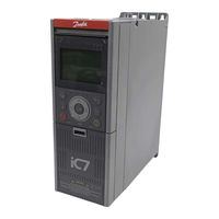
Danfoss iC7 Series Manuals
Manuals and User Guides for Danfoss iC7 Series. We have
44
Danfoss iC7 Series manuals available for free PDF download: Application Manual, Design Manual, Operating Manual, Installation Manual
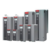
Danfoss iC7 Series Application Manual (374 pages)
Brand:
Danfoss
| Category:
Industrial Equipment
| Size: 7 MB
Table of Contents
Table of Contents
4
Basic Functions
15
Torque Controller
16
Motor Control Features
17
Automatic Motor Adaptation (AMA)
17
Braking of Load
17
Overview of Braking of Load
17
Resistor Braking
18
Overvoltage Control (OVC)
18
DC Brake
18
AC Brake
18
DC Hold
18
Load Sharing
18
Protection Features
18
Grid Protection
18
Drive Protection Features
18
Motor Protection Features
19
Protection of External Filters or Brake Resistors
19
Automatic Derating
19
Monitoring, Logging, and History Log
19
Monitoring Features
19
Event Log
19
Logging and Storage of Data
20
Preventive Maintenance
20
Functional Safety
20
Software Tools
20
Overview of Software Tools
20
Mydrive® Select
20
Mydrive® Harmonics
20
Mydrive® Ecosmart
21
Mydrive® Insight
21
Security Features
21
Motor Control Features for FVC+ and VVC+ Control
21
Compatibility of Motor Control Features for FVC+ and VVC+ Control
21
High Frequency Voltage Injection
24
Profidrive - Standard Telegram
25
Overview
25
Control Word (CTW)
25
Status Word (STW) in Profidrive Standard Telegram 1
26
Profidrive State Machine
27
IC Speed Profile
28
Overview
28
Control Word (CTW)
28
Status Word (STW) in IC Speed Profile
30
User Interfaces
32
Overview of User Interfaces
32
Control Panel
32
Ic7 Control Panel Options
32
Control Panel Elements
33
Control Panel Basic Configurations
35
Starting the Drive and Control Panel Display
35
Understanding Status Screens
35
Adjusting Display Backlight and Contrast
37
Changing the Content of the Status Screens
37
Main Menu and Overall Navigation
37
Changing the Selections of a Parameter
39
Changing a Parameter Value
40
Locking the Control Panel Display
40
Control Panel Shortcuts
41
Backup and Restore
41
Making a System Backup Using the Control Panel
41
Restoring the System Configuration Using the Control Panel
42
Mydrive® Insight
44
Introduction to Mydrive® Insight
44
Advertisement
Danfoss iC7 Series Application Manual (382 pages)
Brand:
Danfoss
| Category:
I/O Systems
| Size: 5 MB
Table of Contents
Table of Contents
4
AC Brake
18
DC Hold
18
Load Sharing
18
Protection Features
18
Grid Protection
18
Drive Protection Features
18
Motor Protection Features
18
Protection of External Filters or Brake Resistors
19
Automatic Derating
19
Monitoring, Logging and History Log
19
Monitoring Features in Motion
19
Event Log
19
Logging and Storage of Data
19
Functional Safety
19
Software Tools
20
Overview of Software Tools
20
Mydrive® Select
20
Mydrive® Harmonics
20
Mydrive® Ecosmart
20
Mydrive® Insight
20
Security Features
20
Motor Control Features for FVC+ and VVC+ Control
21
Compatibility of Motor Control Features for FVC+ and VVC+ Control in Motion
21
High Frequency Voltage Injection
23
Position Control and Motion Features
24
Position Control
24
Position Control Overview
24
Control Configurations
24
Control Loop
26
Position Feedback and the Actual Position
27
Linear Versus Rotary Axis
27
Unit Scaling
28
Position Monitoring
29
Software Position Limits
29
Hardware End Limits
30
Positioning Mode
30
Positioning Types
30
Profile Generator and Reference Handling
32
Control and Status Signals
33
Gear Mode
34
Overview of Gear Mode
34
Synchronization Types
35
Gear Generator and Reference Handling
37
Control and Status
38
Master
38
Homing
39
Overview of Homing
39
One Time Homing Methods
39
Homing on the Fly
41
Danfoss iC7 Series Design Manual (224 pages)
Liquid-cooled System Modules
Brand:
Danfoss
| Category:
Control Unit
| Size: 25 MB
Table of Contents
Table of Contents
3
Introduction
11
Purpose of this Design Guide
11
Additional Resources
11
Planning and Design Support Materials
11
Overview of Available Planning and Design Support Materials
11
Locating Support Information
12
Version History
12
Abbreviations
12
Recommended Disposal
13
Safety
14
Safety Symbols
14
General Safety Considerations
14
Target Group and Necessary Qualifications
15
Danfoss Ic7 Series
16
Overview of Ic7 Series
16
Overview of the Ic7 Series Liquid-Cooled System Modules
17
System Modules
17
Control System of the System Modules
19
Contents of the Delivery
20
Description of the Frame Designation
20
Weights
20
Common DC Bus Drive System
21
Description of the Model Code
22
Labels on the Products
23
Labels on the System Module
23
Labels on Other Components
24
Product Label
25
Lifting the Product
26
Lifting the System Modules
26
Lifting the System Modules with Integration Unit
26
Lifting the Filters
27
Mechanical Installation Considerations
28
Storing the System Module
28
Requirements for the Cabinet
28
Mechanical Installation
28
Installation Requirements
28
Installation Directions
28
Installing System Modules
28
Installing System Modules into a Cabinet Vertically
28
Installing System Modules into a Cabinet Horizontally
30
Installing System Modules into a Cabinet on Their Backsides
30
Installing System Modules with Integration Units
31
Installing System Modules with Integration Units into a Cabinet Vertically
31
Installing System Modules with Integration Units into a Cabinet Horizontally
33
Installing System Modules with Integration Units into a Cabinet on Their Backsides
34
Installing Filters
35
Installing L Filter into a Cabinet, 400 A, 1000 a
35
Installing L Filter into a Cabinet, 1640 a
35
Cooling Requirements
37
Safety in Liquid-Cooling
37
General Information on Cooling
37
Coolant
39
Quality Requirements for the Purified Water
39
Purified Water as Coolant
39
Antifreeze MIX as Coolant
39
Temperature of the Coolant
40
Cooling System
40
Materials
40
Heat Exchanger
41
Flow Rate of the Coolant
41
Flow Rates in Parallel Power Units
42
Volume of the Pipe
43
Pressure Drop and Correction Factors
44
Pressure Drop of IM10L, IM12L, AM10L, AM12L, DM10L and DM12L
45
Pressure Drop of AR10L, IR10L, and Filters
46
Pressure Drop of AR12L, IR12L, and Filters
48
Pressure Drop of the Grid-Side L Filter
50
Pressure Drop of DR10L, DR12L, and Filters
51
Cooling Circuit Connectors
52
Pipe Ferrules
53
Insertion of Pipes into Cooling Circuit Connectors
53
Inlet and Outlet Connectors of System Modules
54
Inlet and Outlet Connectors of System Modules with Integration Units
55
Inlet and Outlet Connectors of the L Filter
56
Cooling Circuit Pipes
56
Advertisement
Danfoss iC7 Series Design Manual (150 pages)
Air-cooled System Modules
Brand:
Danfoss
| Category:
Control Unit
| Size: 20 MB
Table of Contents
Table of Contents
3
Introduction
9
Purpose of this Design Guide
9
Additional Resources
9
Planning and Design Support Materials
9
Overview of Available Planning and Design Support Materials
9
Locating Support Information
10
Version History
10
Abbreviations
10
Recommended Disposal
11
Safety
12
Safety Symbols
12
General Safety Considerations
12
Target Group and Necessary Qualifications
13
Danfoss Ic7 Series
14
Overview of Ic7 Series
14
Overview of the Ic7 Series Air-Cooled System Modules
15
System Modules
15
Contents of the Delivery
15
Checking the Delivery
16
Description of the Frame Designation
16
Weights of the System Modules
16
Lifting the Product
17
Common DC Bus Drive System
19
Description of the Model Code
20
Options
21
Labels on the System Module
23
Labels on Other Components
23
Product Label
24
Mechanical Installation Considerations
26
Storing the System Module
26
Requirements for the Cabinet
26
Installation Direction
26
Cooling Requirements
27
General Cooling Requirements
27
The Quantity of Cooling Air
27
Cooling of System Modules
27
Cooling of System Modules with Integration Units
28
Steering the Airflow
29
Electrical Installation Considerations
31
Cable Requirements
31
Grounding Principles
32
Grounding the Products
32
Prerequisites for Cable Installation
32
Recommended Installation of Motor Cables
34
Cable Requirements for the LCL Filter Fan Supply
35
Connecting the LCL Filter Fan Supply
36
Installation in an Impedance-Grounded (IT) System
37
Changing the EMC Protection Level in an IT System
39
Fuses of the Drive System
41
Guidelines for DC Connections of System Modules
41
Terminals of the System Modules
44
Auxiliary Power Connection of the Power Unit
44
Auxbus Communication
45
Usage of Auxbus
45
Auxbus Cable Requirements
46
Auxbus Grounding Principles
47
Auxbus Terminals of the LCL Filter and the Integration Unit
48
Options and Accessories for the Air-Cooled System Modules
50
Du/Dt Filter
50
Common-Mode Filter
50
LCL Filter
51
The Pre-Charging Unit
51
Control Unit
53
Modular Control Unit
53
Control Board
54
Definitions of the Indicator Lights on the Control Board
55
Control Board Connections
55
Star Coupler Board
57
Definitions of the Indicator Lights on the Star Coupler Board
59
Star Coupler Board Connections
60
I/O and Relay Option Connections
60
I/O and Relay Option Interface
63
Analog Inputs
63
Analog Outputs
64
Digital Inputs
64
Digital Outputs
65
Relay Outputs
65
Analog Reference Voltage Output
66
DC Voltage Output
66
Danfoss iC7 Series Operating Manual (82 pages)
Cooling Modules
Brand:
Danfoss
| Category:
Freezer
| Size: 6 MB
Table of Contents
Table of Contents
3
Introduction
7
Purpose of this Operating Guide
7
Additional Resources
7
Version History
7
Abbreviations
7
Disposal
8
Safety
9
Safety Symbols
9
General Safety Considerations
9
Target Group and Necessary Qualifications
9
Designated Use
10
Safe Operation
10
Product Overview
11
Product Variants
11
Description of the Model Code
11
Outer Dimensions and Weights
12
Receiving the Product
13
Checking the Shipment
13
Storing the Cooling Module
13
Lifting the Cooling Module
13
Mechanical Installation
16
Required Environmental Conditions
16
Installation Preparations
16
Installing the Standalone Cooling Module into the Cabinet
16
Installing the Standalone Cooling Module Without a Cabinet
19
Installing the Enclosed Cooling Module
20
Cooling Installation
22
Safety in Liquid-Cooling
22
The Operating Principle of the Cooling Module
22
Components of the Drive Circuit
23
Components of the External Circuit
24
Direction of Coolant Flow
25
Coolant Quality in the Drive Circuit
26
Quality Requirements for the Purified Water
26
Coolant Quality in the External Circuit
27
Purified Water as Coolant
27
Antifreeze MIX as Coolant
28
Materials
28
Pipe Connections
28
Connecting Pipes with Axilock Joints
30
Location of Valves and Instrumentation
30
Draining the Cooling System
33
Flushing the Pipes
33
Doing the Pressure Test
34
Filling the Cooling System
37
Filling the Cooling System by Progressive Circulation
37
Filling the Cooling System by Forced De-Airing
38
Checking the Pump Rotation Direction
39
Electrical Installation
41
Electrical Safety
41
Electrical Components
41
Danfoss iC7 Series Operating Manual (62 pages)
Automation Functional Safety
Brand:
Danfoss
| Category:
Media Converter
| Size: 5 MB
Table of Contents
Table of Contents
3
Introduction
7
Purpose of this Operating Guide
7
Additional Resources
7
Abbreviations
7
Trademarks
8
Version History
8
Safety
9
Qualified Personnel for Working with Functional Safety
9
General Safety Considerations
9
Functional Safety for Frequency Converters with STO, Not Upgradable (+BEF1)
10
Ic7 Functional Safety
10
Overview
10
System Configuration Security
11
Safe Torque off (STO)
11
STO Activation
11
Automatic/Manual Restart Behavior
11
STO Properties
12
STO Feedback
13
Installation
14
STO Installation for Frequency Converters with Functional Safety Group 1 (STO - Not Upgradable)
14
Connection Examples
16
Commissioning
17
Safety Instructions for Commissioning
17
Commissioning Test
17
Overview
17
Commissioning Test for STO Applications in Manual Restart Mode
18
Commissioning Test for STO Applications in Automatic Restart Mode
18
Operation and Maintenance
19
Functional Tests
19
Conducting Functional Tests
19
Functional Test Using STO Feedback Signal
19
Functional Test Without Using STO Feedback Signal
20
Diagnostic Tests
21
Specifications
22
Functional Safety Standards and Performance
22
Technical Data
23
Operating Conditions
24
Cable Specifications
25
Functional Safety for Frequency Converters, Upgradable (+BEF2)
26
Functional Safety Options
26
Functional Safety System Description
26
Safety Functions
26
Overview of Frequency Converters with STO and SS1-T (+BEF2)
26
STO Activation
27
Configuring Restart and Acknowledgment Behavior
27
Safety Input Properties
28
STO Feedback
29
Parameters for Safety Functions
31
Overview of Safety Function Parameters
31
Danfoss iC7 Series Installation Manual (72 pages)
Liquid-cooled System Modules, Active Front-End, Grid Converter, Inverter, and DC/DC Converter Modules
Brand:
Danfoss
| Category:
Control Unit
| Size: 12 MB
Table of Contents
Table of Contents
3
Safety and Installation Awareness
7
Checking the Delivery and the Contents
7
Unpacking the Product
7
Lifting the System Modules
8
Lifting the System Modules with Integration Unit
8
Lifting the Filters
9
Mechanical Installation
10
Installation Requirements
10
Installation Directions
10
Installing System Modules
10
Installing System Modules into a Cabinet Vertically
10
Installing System Modules into a Cabinet Horizontally
11
Installing System Modules into a Cabinet on Their Backsides
12
Installing System Modules with Integration Units
13
Installing System Modules with Integration Units into a Cabinet Vertically
13
Installing System Modules with Integration Units into a Cabinet Horizontally
15
Installing System Modules with Integration Units into a Cabinet on Their Backsides
16
Installing Filters
17
Installing L Filter into a Cabinet, 400 A, 1000 a
17
Installing L Filter into a Cabinet, 1640 a
17
Cooling
19
Insertion of Pipes into Cooling Circuit Connectors
19
Inlet and Outlet Connectors
19
Inlet and Outlet Connectors of System Modules
19
Inlet and Outlet Connectors of System Modules with Integration Units
20
Inlet and Outlet Connectors of the L Filter
21
Cooling Circuit Pipes
21
Bending the Pipes
22
Bending Pipes in the Air
22
Bending Pipes with a Bending Jig
23
Electrical Installation
25
Control System of the System Modules
25
Grounding Principles
25
Prerequisites for Cable Installation
25
Recommended Installation of Motor Cables
27
Installing the Cables
28
Field Cabling Installation
28
Installing the Cables, AFE and GC (AR10L, AR12L)
28
Installing the Cables, INU (IR10L, IR12L)
29
Installing the Cables, DC/DC Converter (DR10L, DR12L)
30
Installing the Cables, INU (IM10L, IM12L), AFE and CG (AM10L, AM12L), and DC/DC Converter (DM10L, DM12L)
31
Installing the Cables with the Power Terminal Adapter, INU IR10L, IR12L
31
Installing the Cables with the Power Terminal Adapter, INU IM10L, IM12L
32
Installing the DC Fuses to the DC Terminals
33
Changing the EMC Protection Level
35
Changing the EMC Protection Level, AR10L
35
Changing the EMC Protection Level, AR12L
36
Changing the EMC Protection Level, LC Filter, OF7Z1, 380 a
37
Changing the EMC Protection Level, LC Filter, OF7Z1, 760 a
38
Danfoss iC7 Series Operating Manual (44 pages)
Air-cooled and Liquid-cooled System Modules
Brand:
Danfoss
| Category:
Control Unit
| Size: 3 MB
Table of Contents
Table of Contents
3
1 Introduction
7
Purpose of this Operating Guide
7
Additional Resources
7
Abbreviations
7
Version History
8
2 Safety
9
Safety Symbols
9
Qualified Personnel for Working with Functional Safety
9
General Safety Considerations
10
3 Ic7 Functional Safety
11
Functional Safety Options
11
Functional Safety System Description
11
System Modules with Different Safety Functions
12
Overview
12
Safe Torque off (STO)
13
STO Activation
13
Configuring Restart and Acknowledgment Behavior
13
STO Properties
14
STO Feedback
15
4 Parameters for Safety Functions
17
Overview
17
General Functional Safety Parameters
17
Failure Configuration
18
Pairing Control Units and Power Units
18
Safe Torque off (STO)
19
Safe Stop 1 Time-Controlled (SS1-T)
20
Saving to Device
21
Validating and Generating a Commissioning Report
22
5 Installation
23
Installation for System Modules with +BEF2
23
6 Configuration Tools
26
Overview
26
System Configuration Security
26
Preparing for a PC Connection
26
Mydrive Insight
27
Installing Mydrive® Insight
27
Backing up and Restoring Parameters
27
Performing a Factory Reset
27
Updating Software
27
7 Commissioning
29
Commissioning Safety
29
Commissioning Test
29
Commissioning Checklist
29
Commissioning Test for Safety Function STO
30
Commissioning Test for Safety Function Safe Stop 1 Time-Controlled (SS1-T)
31
Validating and Generating a Commissioning Report
32
8 Operation and Maintenance
33
Overview of Functional Tests
33
Diagnostics
33
Installation and Maintenance in High Altitudes
33
Drive Replacement
34
Danfoss iC7 Series Operating Manual (42 pages)
Brand:
Danfoss
| Category:
Industrial Equipment
| Size: 8 MB
Table of Contents
Table of Contents
3
Introduction
5
Purpose of the Operating Guide
5
Additional Resources
5
Safety Symbols
5
Qualified Personnel
5
Safety Precautions
5
Abbreviations
7
Version History
7
Overview
8
Ethernet/Ip Features and Technical Data
8
Communication Profiles and Objects
8
IC Speed Profile
9
Control Word (CTW) in IC Speed Profile
9
Status Word (STW) in IC Speed Profile
10
Profidrive
11
Control Word (CTW) in Profidrive
11
Status Word (STW) in Profidrive
12
Profidrive State Machine
13
Network Topologies
14
Line Topology
14
Star Topology
15
Ring Topology
16
Fieldbus Cable Connections
17
Prerequisites for Installation
17
Installation in Frequency Converters
17
Communication Interface X1/X2 in Frames FA02-FA12
17
Communication Interface X1/X2 in Frames FK06-FK12
17
Installation in System Modules
18
Communication Interface X1/X2 in System Modules
18
EMC-Compliant Installation
19
Grounding
19
Cable Routing
19
Ethernet/Ip Configuration
21
Configuring Ethernet Interface
21
General Connectivity Settings
21
Configuring Ethernet/Ip Scanner
23
Configuring Rockwell Scanner
24
Configuring Ethernet/Ip Connections
26
IO Connection Settings
26
Class-1 Connection
28
I/O Assembly Instances
28
Connection Manager
28
Transport Types
28
Class-3 Connection
29
Unconnected Messages, UCMM
29
Ic7-Automation Reference Handling
29
Troubleshooting
31
Configuring Port Mirroring Settings
31
Identifying a Drive
31
Danfoss iC7 Series Operating Manual (42 pages)
PROFINET RT
Brand:
Danfoss
| Category:
Industrial Equipment
| Size: 3 MB
Table of Contents
Table of Contents
3
Introduction and Safety
5
Purpose of the Operating Guide
5
Additional Resources
5
Safety Symbols
5
Qualified Personnel
6
Safety Precautions
6
Abbreviations
7
Trademarks
8
Version History
8
Product Overview
10
PROFINET Features and Technical Data
10
Communication Profiles and Objects
10
IC Speed Profile
11
Overview
11
Control Word (CTW)
11
Status Word (STW)
12
Profidrive - Standard Telegram
13
Overview
13
Control Word (CTW)
13
Status Word (STW)
15
Profidrive State Machine
16
IC Active Front End Profile
16
Overview
16
Control Word (CTW)
17
Status Word
18
Submodules
19
Functional Extension Options
19
Network Topologies
20
Overview
20
Line Topology
20
Star Topology
21
Ring Topology
22
Fieldbus Cable Connections
24
Prerequisites for Installation
24
Communication Interface X1/X2 in Frames FA02-FA12
24
Communication Interface X1/X2 in Frames FK06-FK12
24
Communication Interface X1/X2 in System Modules
25
EMC-Compliant Installation
26
Overview
26
Grounding
26
Cable Routing
27
Configuration
28
Configuring the Ethernet Interface
28
Configuring Name of Station
28
GSDML File (Device Description File)
29
Reference and Main Actual Handling
29
Propulsion & Machinery Application
29
Active Front End Application
30
General Connectivity Settings
31
Danfoss iC7 Series Operating Manual (42 pages)
Brand:
Danfoss
| Category:
Industrial Equipment
| Size: 8 MB
Table of Contents
Table of Contents
3
Introduction and Safety
5
Purpose of this Operating Guide
5
Additional Resources
5
Safety Symbols
5
Qualified Personnel
5
Safety Precautions
5
Abbreviations
7
Version History
7
Overview
8
Modbus Features and Technical Data
8
Communication Profiles and Objects
8
IC Speed Profile
9
Control Word (CTW) in IC Speed Profile
9
Status Word (STW) in IC Speed Profile
10
Profidrive - Standard Telegram
11
Control Word (CTW) in Profidrive Standard Telegram
11
Status Word (STW) in Profidrive Standard Telegram
12
Profidrive State Machine
13
IC Grid Converter Profile
14
Control Word (CTW) in IC Grid Converter
14
Status Word (STW) in IC Grid Converter
16
IC DC/DC Converter Profile
17
Control Word (CTW) in IC DC/DC Converter
17
Status Word (STW) in IC DC/DC Converter
18
Network Topologies
18
Line Topology
19
Star Topology
20
Ring Topology
20
Modbus Data Mapping
22
Mapping Modbus Coils
22
Mapping Modbus Holding Registers
23
Mapping Modbus Input Registers
25
Setting Permissions
26
Saving Modbus Configuration to a Device
26
Fieldbus Cable Connections
27
Prerequisites for Installation
27
Installation in Frequency Converters
27
Communication Interface X1/X2 in Frames FA02-FA12
27
Communication Interface X1/X2 in Frames FK06-FK12
27
Installation in System Modules
28
Communication Interface X1/X2 in System Modules
28
EMC-Compliant Installation
29
Grounding
29
Cable Routing
29
Modbus Configuration
31
General Connectivity Settings
31
Ic7-Automation Reference Handling
32
Configuring Ethernet Interface
32
Configuring Parallel Redundancy Protocol
34
Danfoss iC7 Series Installation Manual (48 pages)
Automation Air-cooled Enclosed Drives 206/385–1710 A
Brand:
Danfoss
| Category:
DC Drives
| Size: 7 MB
Table of Contents
Table of Contents
3
Overview
5
Safety and Installation Awareness
5
Checking the Delivery and the Contents
5
Lifting the Enclosed Drive
5
Mechanical Installation
7
Installation Requirements
7
Installing the Enclosed Drive
7
Installing the Enclosed Drives Back to Back
7
Installing the IP21 Top Cover
8
Installing the Back-Channel Cooling Option
9
Electrical Installation
11
Grounding Principles
11
Prerequisites for Cable Installation
11
Installing Power Cables
13
Installing the Power Cables through the Bottom
13
Installing the Power Cables through the Top (+KCIT or +KDOT)
14
Installing the Brake Cables, FE9, FE10
16
Power Cabling Floor Components, UL
16
Checking the Settings for the Auxiliary AC Voltage Transformer (+IHAT)
17
Parameter Settings for IT Mains
17
Control and Option Installation
18
Control Compartment Connections
18
I/O and Relay Option Connections
19
Control Cable Routing
22
Installing Boards to the Control Compartment
26
Wiring of the I/O and Relay Options
27
Installing the Control Cables
27
Installing the Microsd Card
30
Commissioning
31
Commissioning the Enclosed Drive
31
Preparing for a PC Connection
31
Pre-Charging the Drive
32
Measuring the Insulation Resistance
33
Measuring the Insulation Resistance of the Motor Cable
33
Measuring the Insulation Resistance of the Mains Cable
33
Measuring the Insulation Resistance of the Motor
33
Specifications
34
Tightening Torques
34
Cable Sizes
34
List of Cable Size Information
34
Mains Cable Size Recommendations, 380-500
35
Motor Cable Size Recommendations, 380-500
37
Mains Cable Size Recommendations, UL 480
39
Motor Cable Size Recommendations, UL 480
40
Brake Cable Size Recommendations
41
Brake Cable Size Recommendations, UL
42
Fuses
42
Fuse Size Tables
42
AC Fuses, 380-500 V AC
43
DC Fuses, 465-800 V DC
44
External Fuses on External Supply for Input Devices
44
Danfoss iC7 Series Operating Manual (64 pages)
Functional Extension Options
Brand:
Danfoss
| Category:
Industrial Equipment
| Size: 17 MB
Table of Contents
Table of Contents
3
Introduction
5
Purpose of the Operating Guide
5
Additional Resources
5
Version History
5
Safety
6
Safety Symbols
6
Safety and Installation Awareness
6
Configuration
7
Configuration Overview
7
Physical Location and Corresponding Software Address
7
Installation
9
Verifying the Shipment and Contents
9
Items Supplied
9
Installing Functional Extensions in Frequency Converters
9
Installing Boards to the Modular Control Unit
13
Encoder/Resolver Installation and Configuration
14
Encoder/Resolver Option OC7M0
14
Required Tools
14
Pin Assignment for Encoder/Resolver OC7M0
15
Encoder/Resolver Option OC7M0 Specifications
15
Setup and Connection Examples for Encoder/Resolver OC7M0
17
Parameter Descriptions for Encoder/Resolver
36
Relay Option Installation and Configuration
44
Relay Option OC7R0
44
Required Tools
44
Pin Assignment for Relay Option OC7R0
44
Relay Option OC7R0 Specifications
44
Setup and Connection Examples for Relay Option OC7R0
45
Wiring Diagrams for Different Operating Altitudes
46
Parameter Descriptions for Relay Option OC7R0
47
General Purpose I/O Installation and Configuration
49
General Purpose I/O OC7C0
49
Danfoss iC7 Series Installation Manual (80 pages)
iC7-Automation Frequency Converters
Brand:
Danfoss
| Category:
Industrial Equipment
| Size: 13 MB
Table of Contents
Required Tools
3
EMC-Compliant Installation
3
Installing the Drive
4
Erforderliche Werkzeuge
7
Outils Nécessaires
11
Installazione
15
Utensili Richiesti
15
Ferramentas Necessárias
19
Instalación
23
Herramientas Necesarias
23
Power Unit
57
Control Board
57
Danfoss iC7 Series Operating Manual (32 pages)
PROFINET
Brand:
Danfoss
| Category:
DC Drives
| Size: 16 MB
Table of Contents
Table of Contents
3
Introduction and Safety
5
Purpose of the Operating Guide
5
Additional Resources
5
Safety Symbols
5
Safety Precautions
5
Abbreviations
7
Version History
8
Product Overview
9
PROFINET Features and Technical Data
9
Communication Profiles and Objects
9
IC Speed Profile
10
Control Word (CTW) in IC Speed Profile
10
Status Word (STW) in IC Speed Profile
11
Profidrive - Standard Telegram
12
Control Word (CTW) in Profidrive Standard Telegram
12
Status Word (STW) in Profidrive Standard Telegram
13
Profidrive State Machine
14
Submodules
15
Functional Extension Options
16
Network Topologies
16
Line Topology
16
Star Topology
17
Ring Topology
18
Fieldbus Cable Connections
20
Prerequisites for Installation
20
Communication Interface X1/X2 in Frames FA02-FA12
20
Communication Interface X1/X2 in Frames FK06-FK12
20
EMC-Compliant Installation
21
Grounding
22
Cable Routing
22
PROFINET Configuration
23
Configuring the Ethernet Interface
23
Configuring PROFINET Name of Station
23
GSDML (Device Description File)
24
Reference Handling
24
General Connectivity Settings
24
Parameter Access
27
Parameter Access Overview
27
Profidrive Parameter Numbers
27
Troubleshooting
28
Diagnostics
28
PROFINET Report
28
Configuring Port Mirroring Settings
29
Identifying a Drive
29
Fieldbus Indicator Leds
29
Danfoss iC7 Series Operating Manual (38 pages)
Automation EtherCAT
Brand:
Danfoss
| Category:
Industrial Equipment
| Size: 6 MB
Table of Contents
Table of Contents
3
Troubleshooting
4
Introduction and Safety
5
Purpose of the Operating Guide
5
Additional Resources
5
Safety Symbols
5
Qualified Personnel
6
Safety Precautions
6
Abbreviations
7
Trademarks
8
Version History
9
Product Overview
10
Ethercat Features and Technical Data
10
Communication Profiles and Objects
10
IC Speed Profile
11
IC Motion Profile
13
Cia 402 - Velocity Mode
17
Control Word
17
Status Word
18
Fieldbus Cable Connections
22
Prerequisites for Installation
22
Communication Interface X1/X2 in Frequency Converters
22
Ethercat Port Assignment
23
EMC-Compliant Installation
24
Configuration
26
Ethercat Subdevice Information File
26
Reference Handling
26
Connectivity Settings
27
Parameter Access
29
Overview
29
Accessing Parameters
29
Danfoss iC7 Series Operating Manual (32 pages)
Functional Extensions
Brand:
Danfoss
| Category:
DC Drives
| Size: 1 MB
Table of Contents
Table of Contents
3
Introduction
4
Purpose of the Operating Guide
4
Additional Resources
4
Version History
4
Safety
5
Safety Symbols
5
Safety and Installation Awareness
5
Configuration
6
Configuration Overview
6
Installation
7
Checking the Shipment
7
Installing Functional Extensions in Frequency Converters
7
Installing Boards to the Modular Control Unit
10
Encoder/Resolver Installation and Configuration
11
Encoder/Resolver Option OC7M0
11
Required Tools
11
Items Supplied
11
Pin Assignment for Encoder/Resolver OC7M0
11
Encoder/Resolver Option OC7M0 Specifications
12
Setup and Connection Examples for Encoder/Resolver OC7M0
14
Incremental Encoder
14
Sincos Encoder
19
SSI Encoder
19
Endat Encoder
20
Parameter Descriptions for Encoder/Resolver
22
Relay Option Installation and Configuration
26
Relay Option OC7R0
26
Required Tools
26
Items Supplied
26
Pin Assignment for Relay Option OC7R0
26
Relay Option OC7R0 Specifications
26
Setup and Connection Examples for Relay Option OC7R0
27
Wiring Diagrams for Different Operating Altitudes
28
Parameter Descriptions for Relay Option OC7R0
29
Danfoss iC7 Series Operating Manual (24 pages)
Frequency Converters, 1.3–106 A
Brand:
Danfoss
| Category:
Media Converter
| Size: 1 MB
Table of Contents
Table of Contents
3
Introduction
5
Version History
5
Purpose of this Operating Guide
5
Additional Resources
5
Abbreviations
5
Safety
7
Qualified Personnel for Working with Functional Safety
7
General Safety Considerations
7
Ic7 Functional Safety
8
Safe Torque off (STO)
8
STO Activation
8
Automatic/Manual Restart Behavior
8
System Configuration Security
8
Frequency Converters with Functional Safety Group 1 (Not Upgradable)
9
STO Properties
9
STO Failure
10
STO Feedback
10
Installation
12
STO Installation for Frequency Converters with Functional Safety Group 1 (STO - Not Upgradable)
12
Connection Examples
13
Commissioning
15
Safety Instructions for Commissioning
15
Commissioning Test
15
Commissioning Test for STO Applications in Manual Restart Mode
15
Commissioning Test for STO Applications in Automatic Restart Mode
16
Operation and Maintenance
17
Functional Tests
17
Functional Test Using the STO Feedback Signal
17
Functional Test Without Using the STO Feedback Signal
17
Diagnostic Tests
18
Specifications
20
Functional Safety Standards and Performance
20
Technical Data
21
Danfoss iC7 Series Operating Manual (20 pages)
Voltage Measurement Option
Brand:
Danfoss
| Category:
Measuring Instruments
| Size: 3 MB
Table of Contents
Table of Contents
3
1 Introduction
5
Purpose of the Operating Guide
5
Additional Resources
5
Version History
5
2 Safety
6
Safety Symbols
6
Safety Awareness
6
Installation Safety
7
3 Overview
8
Voltage Measurement Option OC7V0
8
Compatibility
8
4 Configuration
9
Configuration Overview
9
Option Slot Addressing in Systems with Modular Control Unit
9
5 Installation
10
Verifying the Shipment and the Contents
10
Items Supplied
10
Required Tools
10
Installing Boards to the Modular Control Unit
10
Installing the Voltage Measurement Option OC7V0
11
Fiber Cable Requirements
12
Terminal and Connector Specifications
12
Installation Example Diagrams
15
6 Application Examples
16
Grid Converter Control
16
Line Filter Energization and Transformer Magnetization
16
Closed-Loop AC Voltage Control
17
External Grid Synchronization
17
Danfoss iC7 Series Operating Manual (24 pages)
Encoder/Resolver Option
Brand:
Danfoss
| Category:
Control Unit
| Size: 1 MB
Table of Contents
Table of Contents
3
Introduction
4
Version History
4
Purpose of the Operating Guide
4
Additional Resources
4
Safety
5
Safety Symbols
5
Safety and Installation Awareness
5
Configuration
6
Configuration Overview
6
Encoder/Resolver Installation and Configuration
7
Encoder/Resolver Option OC7M0
7
Tools Needed
7
Checking the Shipment
7
Items Supplied
8
Installing Functional Extensions in Frequency Converters
8
Pin Assignment for Encoder/Resolver OC7M0
11
Encoder/Resolver Option OC7M0 Specifications
11
Setup and Connection Examples for Encoder/Resolver OC7M0
13
Incremental Encoder
13
SSI Encoder
17
Parameter Descriptions for Encoder/Resolver
20
Danfoss iC7 Series Installation Manual (36 pages)
Frequency Converters
Brand:
Danfoss
| Category:
Media Converter
| Size: 5 MB
Danfoss iC7 Series Installation Manual (24 pages)
Automation Frequency Converters
Brand:
Danfoss
| Category:
Media Converter
| Size: 11 MB
Table of Contents
Required Tools
3
EMC-Compliant Installation
3
Installing the Drive
4
Commissioning Test
5
Power Unit
6
Control Board
6
Danfoss iC7 Series Installation Manual (22 pages)
Liquid-cooled DC Filter
Brand:
Danfoss
| Category:
Water Filtration Systems
| Size: 1 MB
Table of Contents
Mechanical Installation
2
Cooling Requirements
5
Electrical Installation Safety
8
Cable Requirements
8
Installing the Cables
10
Wiring Diagrams
17
Maintenance
18
Danfoss iC7 Series Installation Manual (21 pages)
Liquid-cooled LC Filter
Brand:
Danfoss
| Category:
Water Filtration Systems
| Size: 1 MB
Table of Contents
Mechanical Installation
2
Cooling Requirements
5
Electrical Installation Safety
8
Cable Requirements
8
Installing the Cables
9
Wiring Diagrams
16
Maintenance
17
Danfoss iC7 Series Installation Manual (21 pages)
Liquid-cooled L Filter
Brand:
Danfoss
| Category:
Water Filtration Systems
| Size: 1 MB
Table of Contents
Mechanical Installation
2
Cooling Requirements
8
Electrical Installation Safety
11
Cable Requirements
12
Installing the Cables
12
Wiring Diagrams
15
Maintenance
16
Danfoss iC7 Series Installation Manual (19 pages)
Air-cooled LCL Filter
Brand:
Danfoss
| Category:
Industrial Equipment
| Size: 3 MB
Table of Contents
Installation Requirements
2
Cooling Requirements
5
Electrical Installation
7
Power Cabling
7
Cable Requirements
7
Installing the Cables
8
Wiring Diagrams
14
Maintenance
16
Danfoss iC7 Series Installation Manual (20 pages)
Liquid-cooled dU/dt Filter
Brand:
Danfoss
| Category:
Water Filtration Systems
| Size: 2 MB
Table of Contents
Mechanical Installation
2
Cooling Requirements
6
Electrical Installation
9
Wiring Diagrams
16
Maintenance
17
Danfoss iC7 Series Installation Manual (18 pages)
In-bottom/Out-back Cooling Kit for FA09-FA10, Frequency Converters
Brand:
Danfoss
| Category:
Media Converter
| Size: 1 MB
Table of Contents
Items Supplied
2
Installation
3
Safety Information
3
Installation Overview
4
Installing the Top Cover
9
Mounting the Frequency Converter
12
Danfoss iC7 Series Installation Manual (18 pages)
Frequency Converters In-back/Out-top Cooling Kit for FA11-FA12
Brand:
Danfoss
| Category:
Media Converter
| Size: 0 MB
Table of Contents
Installation
2
Installation Overview
3
Installing the Bottom Cover
13
Mounting the Frequency Converter
14
Danfoss iC7 Series Installation Manual (16 pages)
In-back/Out-back Cooling Kit for FA09-FA10, Frequency Converters
Brand:
Danfoss
| Category:
Media Converter
| Size: 1 MB
Table of Contents
Items Supplied
2
Installation
3
Safety Information
3
Installation Overview
4
Installing the Top Cover
8
Mounting the Frequency Converter
9
Danfoss iC7 Series Installation Manual (15 pages)
In-back/Out-back Cooling Kit for FA11-FA12
Brand:
Danfoss
| Category:
Freezer
| Size: 0 MB
Table of Contents
Items Supplied
2
Installation
3
Safety Information
3
Installation Overview
4
Installing the Top Cover
9
Installing the Bottom Cover
10
Mounting the Frequency Converter
11
Danfoss iC7 Series Installation Manual (16 pages)
In-bottom/Out-top Cooling Kit for FA09-FA10, Frequency Converters
Brand:
Danfoss
| Category:
Media Converter
| Size: 1 MB
Table of Contents
Items Supplied
2
Installation
3
Safety Information
3
Installation Overview
4
Mounting the Frequency Converter
11
Danfoss iC7 Series Installation Manual (16 pages)
In-back/Out-top Cooling Kit for FA09-FA10, Frequency Converters
Brand:
Danfoss
| Category:
Media Converter
| Size: 1 MB
Table of Contents
Items Supplied
2
Installation
3
Safety Information
3
Installation Overview
4
Mounting the Frequency Converter
10
Danfoss iC7 Series Installation Manual (8 pages)
Pedestal Kit for FK09/FB09 and FK10/FB10, Frequency Converters
Brand:
Danfoss
| Category:
Media Converter
| Size: 0 MB
Table of Contents
1 Overview
1
1.1 Description
1
1.2 Kit Numbers
1
1.3 Items Supplied
1
Installation
2
Safety Information
2
2 Installation
2
2.2 Overview of Pedestal Installation
3
2.3 Lifting the Frequency Converter
4
2.4 Securing the Pedestal to the Floor
4
2.5 Attaching the Frequency Converter
4
2.6 Creating Cable Openings
5
Danfoss iC7 Series Installation Manual (8 pages)
Tall Pedestal Kit for FK11/FB11 and FK12/FB12, Frequency Converters
Brand:
Danfoss
| Category:
Media Converter
| Size: 0 MB
Table of Contents
Overview
1
Description
1
Kit Numbers
1
Items Supplied
1
Installation
2
Safety Information
2
Overview of Pedestal Installation
3
Lifting the Frequency Converter
4
Securing the Pedestal to the Floor
4
Attaching the Frequency Converter
4
Creating Cable Openings
6
Danfoss iC7 Series Installation Manual (16 pages)
In-bottom/Out-back Cooling Kit for FA11-FA12, Frequency Converters
Brand:
Danfoss
| Category:
Media Converter
| Size: 0 MB
Danfoss iC7 Series Installation Manual (14 pages)
In-bottom/Out-top Cooling Kit for FA11-FA12, Frequency Converters
Brand:
Danfoss
| Category:
Media Converter
| Size: 0 MB
Danfoss iC7 Series Installation Manual (10 pages)
Pre-charging Unit for AFE and GC Modules
Brand:
Danfoss
| Category:
Industrial Equipment
| Size: 0 MB
Table of Contents
Cooling Requirements
2
Burn Hazard
3
Electrical Installation Safety
5
Cable Requirements
6
Installing the Power Cables
7
Danfoss iC7 Series Installation Manual (6 pages)
Ground Bar Kit for FK11/FB11 and FK12/FB12, Frequency Converters
Brand:
Danfoss
| Category:
Media Converter
| Size: 0 MB
Table of Contents
Overview
1
Description
1
Kit Numbers
1
Items Supplied
1
Installation
2
Safety Information
2
Assembling the Ground Bars
2
Installing the Ground Bars
4
Danfoss iC7 Series Installation Manual (6 pages)
Fan Power Board Replacement for Fx11–Fx12, Frequency Converters
Brand:
Danfoss
| Category:
Media Converter
| Size: 0 MB
Table of Contents
Overview
1
Description
1
Kit Number
1
Items Supplied
1
Installation
2
Safety Information
2
Removing the Fan Power Board
2
Installing the Fan Power Board
4
Danfoss iC7 Series Installation Manual (6 pages)
Multiwire Kit for Fx09-Fx10, Frequency Converters
Brand:
Danfoss
| Category:
Media Converter
| Size: 0 MB
Table of Contents
Overview
1
Description
1
Kit Number
1
Items Supplied
1
Installation
2
Safety Information
2
Installing the Multiwire Kit
2
Danfoss iC7 Series Installation Manual (10 pages)
In-back/Out-back Cooling Kit for FK11/FB11 and FK12/FB12, Frequency Converters
Brand:
Danfoss
| Category:
Media Converter
| Size: 0 MB
Danfoss iC7 Series Installation Manual (8 pages)
IGBT Module Replacement for Frequency Converters and Drives
Brand:
Danfoss
| Category:
Control Unit
| Size: 0 MB
Danfoss iC7 Series Installation Manual (8 pages)
SCR/Diode Module Replacement for Fx09-Fx12/D1h–D8h/E1h–E4h, Frequency Converters and Drives
Brand:
Danfoss
| Category:
Media Converter
| Size: 0 MB
Advertisement
Related Products
Danfoss iC7-60SAIN05-385A
Danfoss iC7-60SAIN05-480A
Danfoss iC7-60SAIN05-590A
Danfoss iC7-60SAIN05-658A
Danfoss iC7-60SAIN05-730A
Danfoss iC7-60SAIN05-820A
Danfoss iC7-60SAIN05-880A
Danfoss iC7-60SAIN05-1000
Danfoss iC7-60SAIN05-1100
Danfoss iC7-60SAIN05-1260
Danfoss Categories
Controller
DC Drives
Thermostat
Control Unit
Industrial Equipment
More Danfoss Manuals
Login
Sign In
OR
Sign in with Facebook
Sign in with Google
Upload manual
Upload from disk
Upload from URL