
Related Manuals for Thermo Scientific EASY-nLC 1200


Summary of Contents for Thermo Scientific EASY-nLC 1200
- Page 1 Thermo EASY-nLC 1200 Troubleshooting and Maintenance Guide Touch-screen application version 4.2 60053-97274 Revision C 2019...
- Page 2 Terms and Conditions of Sale, which Terms and Conditions of Sale shall govern all conflicting information between the two documents. Release history: Revision C, 2019 Hardware versions: EASY-nLC 1200 instrument. Software version: Touch-screen software version 4.2 For Research Use Only. Not for use in diagnostic procedures.
- Page 3 Notice on Lifting and Handling of Thermo Scientific Instruments For your safety, and in compliance with international regulations, the physical handling of this Thermo Fisher Scientific instrument requires a team effort to lift and/or move the instrument.
- Page 4 Notice on the Proper Use of Thermo Scientific Instruments In compliance with international regulations: This instrument must be used in the manner specified by Thermo Fisher Scientific to ensure protections provided by the instrument are not impaired. Deviations from specified instructions on the proper use of the instrument include changes to the system and part replacement.
- Page 5 WEEE Compliance This product complies with the European Union’s Waste Electrical & Electronic Equipment (WEEE) Directive 2002/96/EC. It is marked with the following symbol: Thermo Fisher Scientific is registered with B2B Compliance (B2Bcompliance.org.uk) in the UK and with the European Recycling Platform (ERP-recycling.org) in all other countries of the European Union and in Norway. If this product is located in Europe and you want to participate in the Thermo Fisher Scientific Business-to-Business (B2B) Recycling Program, send an email request to weee.recycle@thermofisher.com...
- Page 6 Conformité DEEE Ce produit est conforme avec la directive européenne (2002/96/EC) des Déchets d'Equipements Electriques et Electroniques (DEEE). Il est marqué par le symbole suivant: Thermo Fisher Scientific s'est associé avec une ou plusieurs sociétés de recyclage dans chaque état membre de l’Union Européenne et ce produit devrait être collecté...
- Page 7 San Jose products. im Unklaren sind, setzen Sie sich, bevor Sie póngase en contacto con el personal de servicio técnico l’assistance technique pour les produits Thermo Scientific fortfahren, mit dem technischen Support für de los productos Thermo Scientific San Jose.
- Page 8 Technical Support for Thermo Scientific im unklaren sind, setzen Sie sich, bevor Sie póngase en contacto con el personal de servicio técnico l’assistance technique pour les produits Thermo Scientific San Jose products. fortfahren, mit Ihrer lokalen technischen de los productos Thermo Scientific San Jose.
- Page 9 す。この標識記号は機器にも表示されています。この危険の詳細につい 危险的详细信息,参阅适当的仪器手册。若对任何步骤的安全事项有疑 This symbol also appears on the ては、機器のマニュアルを参照してください。 问,联系 Thermo Scientific San Jose 产品的技术支持中心。 手順の安全性にご不明な点がある場合は、Thermo Scientific San Jose 製品の instrument. For details about the hazard, テクニカルサポートまでお問い合わせください。 refer to the instrument manual. When the safety of a procedure is questionable, contact Technical Support for Thermo Scientific San Jose products.
- Page 10 作業の障害物 : 床にあるコード、ホース、その他の物体に注意してく 绊倒危险:注意地面上的线、管或其他物品。 or other objects located on the floor. ださい。 When the safety of a procedure is 手順の安全性にご不明な点がある場合は、Thermo Scientific San Jose 製品の 如对安全程序有疑问,联系 Thermo Scientific San Jose 产品的技术支持 questionable, contact Technical Support テクニカルサポートまでお問い合わせください。 中心。 for Thermo Scientific San Jose products.
-
Page 11: Table Of Contents
Field Service Repairs ..........30 Thermo Scientific EASY-nLC 1200 Troubleshooting & Maintenance Guide... - Page 12 Replacing a Pressure Sensor ........89 EASY-nLC 1200 Troubleshooting & Maintenance Guide...
- Page 13 Running a System Leak Test ........178 Thermo Scientific EASY-nLC 1200 Troubleshooting & Maintenance Guide xiii...
- Page 14 Ordering Information ......... . . 267 EASY-nLC 1200 Troubleshooting & Maintenance Guide...
- Page 15 Contents Solvent System Schematic for the EASY-nLC 1200 Instrument ... 268 Common Replacement Parts ........270 Common Replacement Parts for the EASY-nLC 1200 Instrument .
- Page 16 Contents EASY-nLC 1200 Troubleshooting & Maintenance Guide Thermo Scientific...
-
Page 17: Preface
In addition to this guide, Thermo Fisher Scientific provides the following documents for the EASY-nLC instrument as PDF files: • EASY-nLC 1200 User Guide for the Xcalibur Data System • EASY-nLC 1200 Preinstallation Requirements Guide • EASY-nLC 1200 Getting Started Guide •... -
Page 18: Safety And Special Notices
Preface The EASY-nLC instrument also ships with a printed copy of the Safety and Regulatory Guide. This guide contains important safety information about Thermo Scientific™ liquid chromatography (LC) and mass spectrometry (MS) systems. Make sure that all lab personnel have read and have access to this document. - Page 19 Note Highlights information of general interest. Tip Highlights helpful information that can make a task easier. Thermo Scientific EASY-nLC 1200 Troubleshooting and Maintenance Guide...
-
Page 20: Contacting Us
QR code, which opens your email application or browser. Contact us Customer Service and Sales Technical Support (U.S.) 1 (800) 532-4752 (U.S.) 1 (800) 532-4752 (U.S.) 1 (561) 688-8731 (U.S.) 1 (561) 688-8736 us.customer-support.analyze us.techsupport.analyze @thermofisher.com @thermofisher.com EASY-nLC 1200 Troubleshooting and Maintenance Guide Thermo Scientific... - Page 21 • Send an email message to Technical Publications (techpubs-lcms@thermofisher.com). • Complete a survey at www.surveymonkey.com/s/PQM6P62. ❖ To order consumable and spare parts for the EASY-nLC instrument For the EASY-nLC 1200 instrument, go to https://www.thermofisher.com/order/catalog/product/LC140 Thermo Scientific EASY-nLC 1200 Troubleshooting and Maintenance Guide...
- Page 22 Preface xxii EASY-nLC 1200 Troubleshooting and Maintenance Guide Thermo Scientific...
-
Page 23: Introduction
XYZ robot that moves to the sample location, and a syringe pump that draws only the user-specified sample volume. The EASY-nLC 1200 instrument operates in the ultra-high-performance pressure range of 0 to 1200 bar. Figure 1. -
Page 24: Hardware Components
A and B when these pumps empty solvent to waste. This waste beaker also collects solvent delivered by pump A during the precolumn equilibration and sample loading steps (for a two-column setup). EASY-nLC 1200 Troubleshooting & Maintenance Guide Thermo Scientific... - Page 25 Introduction Hardware Components Figure 2 shows the ASC autosampler model that is installed in the EASY-nLC 1200 instrument. Figure 2. ASC autosampler model y axis (left and right) z-axis needle holder Sample vial tray x axis (in and out) Thermo Scientific...
-
Page 26: Solvent System Components Behind The Right Side Panel
(valve S). Note Acetonitrile concentrations greater than 95% reduce the lifetime of system components. A concentration of 80% acetonitrile in water is recommended for solvent B EASY-nLC 1200 Troubleshooting & Maintenance Guide Thermo Scientific... - Page 27 You can access the solvent system components by removing the instrument’s right side panel, which is secured to the housing with three captive quarter-turn screws. Figure 4 shows the solvent system components for the EASY-nLC 1200 instrument. Thermo Scientific EASY-nLC 1200 Troubleshooting & Maintenance Guide...
- Page 28 Introduction Hardware Components Figure 4. Solvent system components behind the right panel of the EASY-nLC 1200 instrument Solvent A check valve assembly Solvent A check valve assembly Autosampler needle Four 3-position, 6-port valves Pressure sensor S Pressure sensors A and B...
- Page 29 The piston seal allows the piston to move freely within the pump head. The piston seal is made of an extremely strong thermoplastic. The seal for the EASY-nLC 1200 pumps contains a wire spring that forces the inside flange of the seal against the piston to prevent leaks. The seals are not leak proof.
- Page 30 Introduction Hardware Components Figure 5. Syringe pump components (showing the pump head removed from the pump body) EASY-nLC 1200 syringe pump (PLU model) Pump head Piston seal Backup ring Piston LED panel Rotary switch Pump body Stepper motor The syringe pumps perform these functions:...
- Page 31 Introduction Hardware Components The LED panels for the pump module installed in the EASY-nLC 1200 instrument provide the following status informations. States Flow sensor for Illuminates blue—the instrument is turned on and the flow sensor is Pumps A and B connected to the pump.
- Page 32 “Flow Sensors” page CAUTION Solvent B acetonitrile concentration >95% can damage the instrument! The EASY-nLC 1200 instrument uses two flow sensors with a maximum measuring range of 4.5 µL/min. Check Valve Assemblies When the corresponding high-pressure (6-port rotary) valves for pumps A or B are in position 1–2, the check valves perform these functions:...
- Page 33 Note The EASY-nLC solvent system contains three subsystems, one for each pump. A subsystem includes the pump, the pressure sensor, the solvent lines to and from the pressure sensor, and the rotary valve. Thermo Scientific EASY-nLC 1200 Troubleshooting & Maintenance Guide...
- Page 34 Blocks the solvent flow through the valve to the waste beaker. The EASY-nLC is designed as a front end system for mass spectrometers. In this configuration, electrical currents leakages, originating from the MS high voltage, can flow towards the EASY-nLC EASY-nLC 1200 Troubleshooting & Maintenance Guide Thermo Scientific...
- Page 35 • • • • • • • • IMPORTANT Removal of the grounding adapter from valve S (port 3) and Valve W (port 2) will lead to irreparable damage to the valves! Thermo Scientific EASY-nLC 1200 Troubleshooting & Maintenance Guide...
- Page 36 The nanoViper fitting connects to port 1 of valve S. Figure 11. Autosampler needle for the ASC autosampler Plastic stop PEEK nut Needle retainer nanoViper fitting EASY-nLC 1200 Troubleshooting & Maintenance Guide Thermo Scientific...
-
Page 37: Computer And Autosampler Behind The Left Side Panel
Figure 12. Internal features (behind the left side panel) Integrated computer Needle tubing Needle guide Autosampler Enclosed refrigerated sample compartment Thermo Scientific EASY-nLC 1200 Troubleshooting & Maintenance Guide... -
Page 38: Back Panel
Two ports for keyboard or mouse or removable USB storage device For 10/100 MB/sec Ethernet connection P-BUS For communication with add-on devices IN/OUT pins Contact closure (primarily for communication with the mass spectrometer) EASY-nLC 1200 Troubleshooting & Maintenance Guide Thermo Scientific... - Page 39 • For 230 V, T 2.5 AL, 250 V Product order code Instrument serial number LAN MAC ADDRESS MAC address of the embedded computer (Gives the EASY-nLC computer a unique network identifier on your local network.) Thermo Scientific EASY-nLC 1200 Troubleshooting & Maintenance Guide...
-
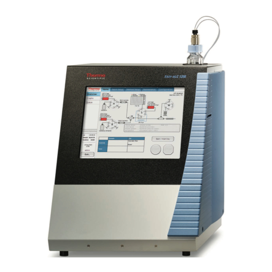
Page 40: Touch-Screen Application
The instrument monitor is a transparent layer of glass that detects finger pressure (even when the operator is wearing gloves) and sends the corresponding commands to the computer (Figure 14). Figure 14. Touch-screen controls Home > Overview page EASY-nLC 1200 Troubleshooting & Maintenance Guide Thermo Scientific... - Page 41 Chapter 3, “Maintenance Scripts and Service Records.” For information about creating methods and sample batches and running sample batches, refer to the EASY-nLC 1200 Getting Started Guide (for the touch-screen application). The EASY-nLC touch-screen application contains five menu tabs at the top of the touch screen.
- Page 42 Introduction Touch-Screen Application The Thermo Scientific logo icon in the upper left corner, the reminders in the left center and the Login button in the lower left corner are always available. To view the version information for the application, press the Logo icon.
-
Page 43: Logging In To The Easy-Nlc Instrument For Maintenance Tasks
2. In the User list, select a user with administrative rights. 3. In the Password box, enter the password for this user. Tip For changing and resetting the password, refer to the EASY-nLC 1200 Getting Started Guide. 4. Press Accept. -
Page 44: Closing Down The Easy-Nlc Instrument
3. After receiving the message that you can safely turn off the instrument, turn off the power switch on the back panel of the instrument. EASY-nLC 1200 Troubleshooting & Maintenance Guide Thermo Scientific... -
Page 45: Specifications
• Performance Specifications • Technical Specifications Performance Specifications Table 3 lists the performance specifications for the EASY-nLC 1200 instrument. Table 3. Performance specification (Sheet 1 of 2) Item Specification Flow range (gradient) 20 to 2000 nL/min Recommended: 100 to 1000 nL/min Flow while loading and Up to 25 µL/min... -
Page 46: Technical Specifications
Max 95% UHPLC/MS-grade acetonitrile with 0.1% formic acid IMPORTANT Use only LC/MS-grade solvents. Safety According to IEC 61010 Solvent compatibility ≤ 95% acetonitrile in water. Wetted parts: Fused silica, PEEK™, 316 stainless steel, zirconium dioxide EASY-nLC 1200 Troubleshooting & Maintenance Guide Thermo Scientific... - Page 47 Two ports for keyboard or mouse or removable USB storage device P-Bus Reserved for instrument add-ons, using the internal EASY-nLC instrument protocol bus: 8-wire control and limited power at 9/24 V Monitor Output for connection of external display Thermo Scientific EASY-nLC 1200 Troubleshooting & Maintenance Guide...
- Page 48 Table 8. Hardware components Item Specification Pumps • 140 µL volume (enough for a >10 h, 0–100% B, 300 nL/min gradient) • 1 nL/min to 300 µL/min flow range • External pressure sensor Rotary valves • 6 ports • 3 positions (1–6, 1–2, or CENTERED) Autosampler •...
-
Page 49: Maintenance Schedule
When working with volatile hazardous chemicals, use an appropriate fume hood. CAUTION Use only LC/MS-grade solvents with the EASY-nLC instrument. Using HPLC-grade solvents and water from laboratory purification systems causes system blockages and poor spray stability. Thermo Scientific EASY-nLC 1200 Troubleshooting & Maintenance Guide... -
Page 50: Weekly Maintenance
❖ To check the cooler temperature Check that the actual plate temperature matches its set point (readout on the Home > Overview page). Allowed maximum deviation from set point temperature is +/- 0,5°C. EASY-nLC 1200 Troubleshooting & Maintenance Guide Thermo Scientific... -
Page 51: Half-Yearly Maintenance
This checks that the flow sensor calibration is working within specifications. Note If the last flow sensor calibration dates back more than 6 months, a reminder will be shown on the home screen. Thermo Scientific EASY-nLC 1200 Troubleshooting & Maintenance Guide... -
Page 52: Yearly Maintenance
However, only a Thermo Fisher Scientific field service engineer can perform these procedures. Attempted repairs by untrained personnel might cause personal injury or irreparably damage the instrument. EASY-nLC 1200 Troubleshooting & Maintenance Guide Thermo Scientific... -
Page 53: Chapter 3 Maintenance Scripts And Service Records
1. On the touch screen, press Maintenance > Scripts. 2. Select a category and then the script for the specific operation you want. You can also schedule some of the scripts for execution using the job queue. Thermo Scientific EASY-nLC 1200 Troubleshooting & Maintenance Guide... -
Page 54: Purge Solvent
• To exchange solvents, use the “Full purge” option. Full purge does 10 purge iterations for pump A and B and 5 for pump S. Note Entering a value of zero (0) for purge iterations refills the pump. EASY-nLC 1200 Troubleshooting & Maintenance Guide Thermo Scientific... -
Page 55: Flush Air
Depending on the solvents, a pumped volume less than 12 µL for the pump module is acceptable. Figure 22 shows the parameters for the Flush Air script. Figure 22. Flush Air script parameters Thermo Scientific EASY-nLC 1200 Troubleshooting & Maintenance Guide... -
Page 56: Precolumn Equilibration
Use this script to equilibrate or flush the precolumn and to determine a suitable flow rate for the sample loading step in your method. Figure 23 shows the parameters for the Precolumn Equilibration script. Figure 23. Precolumn Equilibration script parameters EASY-nLC 1200 Troubleshooting & Maintenance Guide Thermo Scientific... - Page 57 CAUTION Check the maximum pressure rating for the precolumn. Running the instrument at pressures higher than the column’s maximum pressure rating reduces the column lifespan. 3. Press Start. Thermo Scientific EASY-nLC 1200 Troubleshooting & Maintenance Guide...
-
Page 58: Analytical Column Equilibration
1. Open the Analytical Col Equilibration script as follows: a. Press Maintenance > Scripts. b. In the Category list, select Prepare. c. In the Name list, select Analytical Col Equilibration (abbreviated to fit in the space allotted). EASY-nLC 1200 Troubleshooting & Maintenance Guide Thermo Scientific... - Page 59 CAUTION Check the maximum pressure rating for the analytical column. Running the instrument at pressures higher than the maximum pressure rating for the column reduces the column lifespan. 3. Press Start. Thermo Scientific EASY-nLC 1200 Troubleshooting & Maintenance Guide...
-
Page 60: Isocratic Flow
AFC system to accurately control the flow. For details on the AFC system control, refer to the EASY-nLC 1200 Getting Started Guide. Use this script to tune the mass spectrometer at a given B percentage or when cleaning the instrument, the columns, or both. -
Page 61: Column Conditioning
Figure 26. MS Connection script ❖ To run the MS Connection script and test the contact closure connection 1. Connect the contact closure cable to the EASY-nLC instrument and the mass spectrometer. Thermo Scientific EASY-nLC 1200 Troubleshooting & Maintenance Guide... - Page 62 On the EASY-nLC touch screen, press Configuration > Connections. b. For a Thermo Scientific mass spectrometer, make the following selections: • In the Instrument (cable no.) list, select either Thermo Scientific (LC160) or Thermo Scientific Orbitrap Fusion (LC160). • In the Protocol list under Contact Closure Settings, select One-way.
- Page 63 On the EASY-nLC touch screen, press Maintenance > Scripts. The Maintenance Scripts page opens. b. In the Category list, select Test. c. In the Name list, select MS Connection. d. Press Start. Thermo Scientific EASY-nLC 1200 Troubleshooting & Maintenance Guide...
-
Page 64: Sample Pickup
The EASY-nLC instrument sends a contact closure signal to the mass spectrometer. The contact closure signal triggers the mass spectrometer to start scanning. The Scan LED on the front panel of a Thermo Scientific mass spectrometer flashes blue when the contact closure signal is set up correctly. - Page 65 In the Flow box [µL/min], enter the flow rate that pump S uses to aspirate the sample. For aqueous samples enter 20 µL/min. d. In the Position box, specify the position of the sample in the autosampler. See the Position dialog box in Figure 4. Press Start. Thermo Scientific EASY-nLC 1200 Troubleshooting & Maintenance Guide...
-
Page 66: Leaks
When the pressure stabilizes at the specified value, the pump calculates the flow loss based on the pump piston movement required to maintain this pressure. If the flow loss is less than 400 nL/min, the pump passes the leak test. EASY-nLC 1200 Troubleshooting & Maintenance Guide Thermo Scientific... - Page 67 1 in 4 o'clock position). Due to operational reasons, the graphical representation in this guide or in the instrument’s built-in software may show the valves in a different orientation. Please use only the port numbers for identification of port positions. Thermo Scientific EASY-nLC 1200 Troubleshooting & Maintenance Guide...
- Page 68 Viper union stainless steel zero-dead-volume union for 1/16 in. OD tubing EASY-nLC 1200 ES272 UHPLC fused-silica union with the modified Column Out and Waste In lines provided in the UHPLC Liquid Junction Kit EASY-nLC 1200 Troubleshooting & Maintenance Guide Thermo Scientific...
-
Page 69: Pump Torque
“Troubleshooting a Pump That Fails the Leaks Script” page 177. Pump Torque For the pump module in the EASY-nLC 1200 instrument, the Pump Torque script measures the actuator’s ability to generate pressure at predefined torque levels. Figure 33 shows the parameters for the Pump Torque script. -
Page 70: Autosampler Torque
The Autosampler Torque script measures the torque required to move the XYZ robot on each of its axes for the ASC autosampler. Figure 35 shows the Description page of the Autosampler Torque script. EASY-nLC 1200 Troubleshooting & Maintenance Guide Thermo Scientific... -
Page 71: Recording
Figure 35. Autosampler Torque script description Recording Note For service and troubleshooting purposes. The script enables graphs and logging while it is active. Use manual control to manipulate devices. The script can be useful for advanced debugging. Thermo Scientific EASY-nLC 1200 Troubleshooting & Maintenance Guide... -
Page 72: Constant Pressure
Note For service and troubleshooting purposes. This script applies a constant pressure on selected pumps for advanced troubleshooting. Use manual control for manipulating devices. The script can be useful for advanced debugging. EASY-nLC 1200 Troubleshooting & Maintenance Guide Thermo Scientific... -
Page 73: Constant Flow
Note For service and troubleshooting purposes. This script applies a constant flow on selected pumps for advanced troubleshooting. Use manual control for manipulating devices. The script can be useful for advanced debugging. Thermo Scientific EASY-nLC 1200 Troubleshooting & Maintenance Guide... -
Page 74: Flow Sensors
IMPORTANT Because the flow sensor calibration requires a stable operating temperature, ensure that the instrument’s side panels are installed and that the instrument has been on for a minimum of 30 minutes. EASY-nLC 1200 Troubleshooting & Maintenance Guide Thermo Scientific... - Page 75 Select the check boxes for flow sensors A, B, or both that you want to either inspect or calibrate and inspect. Note To calibrate and inspect the flow sensors, this script performs a two-point calibration as follows: Thermo Scientific EASY-nLC 1200 Troubleshooting & Maintenance Guide...
-
Page 76: Reset Pressure Sensor
Reset Pressure Sensor This script auto-zeroes the pressure sensor. IMPORTANT Performing this script incorrectly will compromise the performance of the instrument. Contact your local Thermo Fisher Scientific representative before running this script. EASY-nLC 1200 Troubleshooting & Maintenance Guide Thermo Scientific... -
Page 77: Direct Infusion
❖ To set up the system for a direct infusion experiment 1. Connect an emitter to the Column Out tubing. Figure 41 shows an example of a direct infusion setup for an EASY-nLC 1200 instrument. Figure 41. Setup for a direct infusion experiment 1/32 in. - Page 78 4. If you press Stop before the script ends, follow the instructions in message box that appears to make sure that the current sample is flushed from the system (see Figure 42). EASY-nLC 1200 Troubleshooting & Maintenance Guide Thermo Scientific...
-
Page 79: Keeping Service Records
❖ To record a service action 1. Press Maintenance > Log Book. The Maintenance > Log Book page opens (see Figure 43). Figure 43. Log Book page of the Maintenance menu tab 2. Press Enter Log Entry. Thermo Scientific EASY-nLC 1200 Troubleshooting & Maintenance Guide... - Page 80 2. In the User List, select Any, Admin, or Guest. 3. In the Time From list, select a time. 4. In the Time To list, select a time. 5. Press Search. The search results appear in the Search Result table. EASY-nLC 1200 Troubleshooting & Maintenance Guide Thermo Scientific...
-
Page 81: Checking And Resetting The Device Usage Counters
The Summary view opens. ❖ To reset the volume pumped to zero 1. Open the appropriate Summary page. 2. Press Reset. For a pump, the value in the Intermediate Volume box resets to 0. Thermo Scientific EASY-nLC 1200 Troubleshooting & Maintenance Guide... - Page 82 Maintenance Scripts and Service Records Checking and Resetting the Device Usage Counters EASY-nLC 1200 Troubleshooting & Maintenance Guide Thermo Scientific...
-
Page 83: System Modifications
System Modifications The EASY-nLC 1200 instrument is designed to work with specific analytical columns. If you want to use analytical columns with bare fused-silica ends, you must modify the instrument as described in this chapter. For information about installing columns with bare fused-silica ends, refer to the EASY-nLC 1200 Getting Started Guide. -
Page 84: Installing The Modified Column Out And Waste In Lines
This section describes how to install the modified Column Out and Waste In lines that are supplied in the UHPLC Liquid Junction Kit. For information about setting up the liquid junction, refer to the EASY-nLC 1200 Getting Started Guide. Installing the modified Column Out and Waste In lines requires the following tools and materials. - Page 85 Figure 45 shows the Column Out line connection to valve S and the Waste In line connection to valve W. Figure 45. Right panel removed from the EASY-nLC 1200 instrument Waste In line connected to port 2 of Valve W...
- Page 86 System Modifications Installing the Modified Column Out and Waste In Lines For information about installing analytical columns with bare fused-silica ends, refer to the EASY-nLC 1200 Getting Started Guide. EASY-nLC 1200 Troubleshooting & Maintenance Guide Thermo Scientific...
-
Page 87: Routine Maintenance
Replacing Viper/nanoViper solvent lines • Replacing the Autosampler Needle • Replacing the Sample Loop • Replacing a Pressure Sensor • Replacing a Flow Sensor • Replacing the Hard Drive • Managing the Devices List Thermo Scientific Troubleshooting & Maintenance Guide... -
Page 88: Maintaining A Clean Working Environment
Thermo Fisher Scientific in the solvent A and B bottles and the wash solvent bottle. For information about solvents and solvent blends from Thermo Fisher Scientific, refer to the EASY-nLC 1200 Getting Started Guide. The Optima LC/MS mobile phases can be ordered through www.fishersci.com... -
Page 89: Re-Calibrating Flow Sensors
A or B composition has changed. 6 months after the last flow sensor calibration for flow sensors A and B, a “Flow sensor calibration due” button appears on the left menu panel. Thermo Scientific Troubleshooting & Maintenance Guide... -
Page 90: Replacing The Main Power Fuse
• For 230 Vac, the instrument uses one T 2.5 AL 250 V fuse. Use only UL Listed and CSA-certified fuses, All fuses supplied with the instrument are UL Listed and CSA certified. CAUTION Before removing the fuses, turn off the instrument and remove the power cable. Troubleshooting & Maintenance Guide Thermo Scientific... - Page 91 • Insert the 5 A fuse into the slot that aligns with the white triangle at the end of the 110–120 V line power text. • Insert the 2.5 A fuse into the slot that aligns with the white triangle at the end of the 220–240 V text. Thermo Scientific Troubleshooting & Maintenance Guide...
-
Page 92: Maintaining The Syringe Pumps
CAUTION Overtightening stainless steel viper solvent lines damages their fittings. To replace a pump piston seal and clean the piston, follow these procedures: “Retracting the Piston” page 72 “Replacing the Piston Seal” page 73 Troubleshooting & Maintenance Guide Thermo Scientific... - Page 93 • For pumps A and B, run a pump leak test as described in “Running the Leaks Script after Replacing a Piston Seal or a Pump” page • For pump S, run a sample pickup test as described in “Sample Pickup” page Thermo Scientific Troubleshooting & Maintenance Guide...
-
Page 94: Retracting The Piston
6. Select the check box for the appropriate pump. 7. Press Start. The piston moves backward until it reaches the 140 µL position. 8. To replace the piston seal, go to the piston seal replacement procedure “Replacing the Piston Seal” page 73 Troubleshooting & Maintenance Guide Thermo Scientific... -
Page 95: Replacing The Piston Seal
EASY-nLC Instrument” page 22). 4. Using a #2 Phillips head screwdriver, make a quarter-turn to loosen the three captive screws that secure the right side panel to the instrument housing. Then remove the panel. Thermo Scientific Troubleshooting & Maintenance Guide... - Page 96 Clean the exposed portion of the piston with a lint-free tissue soaked in UHPLC/MS-grade methanol and visually inspect the piston for scratches. Ensure that no solvent runs into the pump. Troubleshooting & Maintenance Guide Thermo Scientific...
- Page 97 Figure 56. Piston seal removal tool CAUTION Use only the dedicated piston seal tool for removing the piston seal from the pump head. Other tools can scratch the inside of the pump head and generate leaks. Thermo Scientific Troubleshooting & Maintenance Guide...
- Page 98 Routine Maintenance Maintaining the Syringe Pumps Figure 57. Removal of old piston seal Troubleshooting & Maintenance Guide Thermo Scientific...
- Page 99 Place the pump head on the guide rods and evenly press it all the way down against the piston seal tool to insert the seal into the pump head (Figure 60). Figure 60. Inserting the piston seal into the pump head Thermo Scientific Troubleshooting & Maintenance Guide...
-
Page 100: Priming The Pump
Press the pump icon for the pump that you want to control. The Pump X dialog box opens, where X identifies the pump (A, B, or S). c. Set the flow rate to 300 µL/min and the volume to 140 µL. d. Press Start. Troubleshooting & Maintenance Guide Thermo Scientific... - Page 101 3. Fill the pump head with solvent as follows: a. Pipette an aliquot of the appropriate solvent into the pump head (Figure 63). Figure 63. Adding solvent to the pump head CAUTION Be careful not to spill solvent on the PCBs. Thermo Scientific Troubleshooting & Maintenance Guide...
-
Page 102: Resetting The Pump Usage Counter
2. Select the pump from the list of devices. 3. Press the Summary tab. 4. Press Reset. The value in the Intermediate Volume box resets to 0. For more information, see “Checking and Resetting the Device Usage Counters” page Troubleshooting & Maintenance Guide Thermo Scientific... -
Page 103: Removing Air After Replacing A Piston Seal Or A Pump
You can easily damage the stainless steel viper tubing that connects the pump to the pressure sensor by overtightening the fittings. If the script detects a leak, replace this flow line. Thermo Scientific Troubleshooting & Maintenance Guide... -
Page 104: Replacing The Check Valves
• For the waste-side check valve, remove the check valve by turning it counterclockwise with your fingers. 5. Screw the new check valve onto the check valve assembly. Slightly tighten the solvent-side check valve to the assembly using a 9/16 in. open-ended wrench. Troubleshooting & Maintenance Guide Thermo Scientific... -
Page 105: Replacing Viper/Nanoviper Solvent Lines
32). Replacing Viper/nanoViper solvent lines IMPORTANT The EASY-nLC 1200 requires nanoViper fitting systems with a specified pressure range up to 1200 bar. Older versions are only specified up to 1000 bar. The new 1200 bar nanoViper fitting system consists of blue PEEK tubing, which distinguishes it... - Page 106 90 degrees from where you felt the initial resistance. IMPORTANT To prevent damage to the sealing surface of the nanoViper fitting, take care not to overtighten the nanoViper fitting. Troubleshooting & Maintenance Guide Thermo Scientific...
-
Page 107: Replacing The Autosampler Needle
3. Move the holder to position A1 as follows: a. Press Home > Overview. b. Press the Autosampler icon. The Autosampler dialog box opens. c. In the XYZ Robot area, select position A1 in the Well box Thermo Scientific Troubleshooting & Maintenance Guide... - Page 108 6. Remove the black needle holder from the slot in the metal plate that separates the solvent system hardware from the autosampler compartment. Removing the fitting requires some gentle movement from both sides of the plate (Figure 68). Troubleshooting & Maintenance Guide Thermo Scientific...
- Page 109 2. Guide the end of the needle that connects to valve S through the large hole in the metal plate that separates the tray compartment from the solvent system compartment. 3. Install the black needle holder in the side plate. 4. Connect the needle to port 1 of valve S as follows: Thermo Scientific Troubleshooting & Maintenance Guide...
-
Page 110: Replacing The Sample Loop
276). b. Disconnect the nanoViper fittings connected to ports 2 and 5 of valve S. Figure 70 shows the sample loop connections for the EASY-nLC 1200 instrument. Figure 70. Sample loop connections for the EASY-nLC 1200 instrument • • • •... -
Page 111: Replacing A Pressure Sensor
IMPORTANT The EASY-nLC 1200 is not compatible with the pressure sensors from the EASY-nLC II and EASY-nLC 1000 and vice versa. The EASY-nLC 1200 pressure sensors are identified by the white connector to the pump PCB and the product number LV2-TI105-01-20K. - Page 112 6. While holding the pressure sensor, use a 2 mm L-hex wrench to remove the two screws that secure the pressure sensor to the bracket. 7. Disconnect the pressure sensor cable from the pump. Figure 72 shows the pressure sensor connections. Troubleshooting & Maintenance Guide Thermo Scientific...
- Page 113 5. Reconnect the pressure sensor cable. 6. Run three iterations of the Purge Solvent script as described in “To run the Purge Solvent script” page 7. Run the Flush Air script as described in “Flush Air” page Thermo Scientific Troubleshooting & Maintenance Guide...
-
Page 114: Replacing A Flow Sensor
• Flow sensor A/B, P/N LC540 IMPORTANT EASY-nLC 1200 flow sensors are compatible with EASY-nLC 1000. EASY-nLC 1000 flow sensors are not compatible with EASY-nLC 1200. Only flow sensors whose serial number is larger than 1528-XXXXX can be used on EASY-nLC 1200 systems (software plausibility check). - Page 115 4. Remove the black cable from the flow sensor (Figure 74). Figure 74. Removing the cable from the flow sensor 5. Using an 2.5 mm hex wrench, remove the two screws that secure the flow sensor to the bracket (Figure 75). Thermo Scientific Troubleshooting & Maintenance Guide...
- Page 116 Replacing a Flow Sensor Figure 75. Removing the screws attaching the flow sensor to the bracket Location of screws that secure flow sensor A 6. Remove the flow sensor (Figure 76). Figure 76. Removing the flow sensor Troubleshooting & Maintenance Guide Thermo Scientific...
-
Page 117: Replacing The Hard Drive
93). 5. Replace the right side panel. 6. Turn on the EASY-nLC 1200 system, and wait one hour for the flow sensor to reach the correct operating temperature. 7. Calibrate the new flow sensor by using the Flow Sensors script (see “Constant Pressure”... - Page 118 3. Pull out the hard-drive drawer, as shown in Figure Figure 79. Pulling out the hard-drive drawer 4. Using a Torx T-10 wrench, remove the four screws underneath the hard-drive drawer that secure the hard drive to the drawer (Figure 80). Troubleshooting & Maintenance Guide Thermo Scientific...
- Page 119 Tip If the SATA cable plug is difficult to access, remove the brass rod that holds the cable down (Figure 82). Use a Torx T-8 wrench to remove the screws. Place the rod back in the drawer afterward. Thermo Scientific Troubleshooting & Maintenance Guide...
- Page 120 8. Set the new administrator password and record the master key as described in the EASY-nLC 1200 Getting Started Guide. 9. Purge the computer hard drive. For further information, refer to “Purging the Computer Hard Drive.”...
-
Page 121: Managing The Devices List
1. Press Maintenance > Devices. 2. Select the device in the Devices list. 3. Press Remove Device. The Remove Device dialog box appears. 4. Press Accept to remove the device and return to the Maintenance > Devices page. Thermo Scientific Troubleshooting & Maintenance Guide... - Page 122 2. Select the device in the Devices list. 3. Press the About tab. The About view contains information about the serial numbers and firmware versions for the rotary valves, piston (syringe) pumps, autosampler, and HPLC. Troubleshooting & Maintenance Guide Thermo Scientific...
-
Page 123: Chapter 6 Field Service Maintenance
“To install the new computer box” page 104 ❖ To remove the computer box 1. Close down the EASY-nLC instrument (see “Closing Down the EASY-nLC Instrument” page 22) and then unplug the power cable. Thermo Scientific EASY-nLC 1200 Troubleshooting & Maintenance Guide... - Page 124 Figure 83 shows these cables in the EASY-nLC 1200 instrument. Figure 83. Cables connected to the computer box in the EASY-nLC 1200 instrument LVDS cable 5. Using a Torx T-10 wrench, remove the three screws that secure the back panel to the...
- Page 125 Raise the top panel by at least one inch. c. Using a Torx T-10 wrench, remove the top two screws that secure the computer box to the instrument (see Figure 85). Thermo Scientific EASY-nLC 1200 Troubleshooting & Maintenance Guide...
- Page 126 Figure 86. Pulling out the computer box e. Lower the top panel. ❖ To install the new computer box 1. Lift the top panel by about one inch. 2. Insert the new computer box into the EASY-nLC housing. EASY-nLC 1200 Troubleshooting & Maintenance Guide Thermo Scientific...
-
Page 127: Replacing The Monitor
• If the instrument was connected to a laboratory LAN port, reconnect the Ethernet cable. • If the instrument is part of a Thermo Scientific LC/MS system, reconnect the Ethernet cable to the back panel of the instrument, and make sure that the other end of the cable connects to the Ethernet switch for the data system hardware. - Page 128 22) and unplug the power cable. 2. To remove the top-front panel from the EASY-nLC 1200 instrument, do the following: a. Using a Torx T-10 wrench, remove the two screws that secure the top-front panel to the top back of the instrument.
- Page 129 16, connect the adapter cable that is supplied with the new monitor to the monitor cable. 4. Connect the USB, LVDS, and monitor cables to the computer box, being careful not to damage the LVDS plug (see Figure 88 page 107). Thermo Scientific EASY-nLC 1200 Troubleshooting & Maintenance Guide...
- Page 130 6. Mount the left side panel to the instrument housing. Then, with a #2 screwdriver, secure the panel by rotating the three captive screws a quarter-turn clockwise. 7. Plug in the power cable, and turn on the EASY-nLC instrument. EASY-nLC 1200 Troubleshooting & Maintenance Guide Thermo Scientific...
-
Page 131: Replacing The Autosampler
101. 4. Unscrew the autosampler needle fitting, and remove or pull up the autosampler needle from the needle holder. Figure 90 shows the autosampler needle connected to the needle holder. Thermo Scientific EASY-nLC 1200 Troubleshooting & Maintenance Guide... - Page 132 5. Unplug the bus cables on the left side of the instrument from the autosampler cooler and horizontal XYZ-axis PCB (see Figure 91). Figure 91. Bus cables Cooler bus cable XYZ-axis PCB bus cable EASY-nLC 1200 Troubleshooting & Maintenance Guide Thermo Scientific...
- Page 133 Figure 93). Figure 93. Horizontal cable bar after removal of screws Bus cable connected to valve B Autosampler frame Horizontal cable bar Back left screw that secures the autosampler to the instrument Thermo Scientific EASY-nLC 1200 Troubleshooting & Maintenance Guide...
- Page 134 Figure Figure 96, and Figure 97): • Remove the screw from the right side of the autosampler (see Figure 95). Figure 95. Removing the screw from the right side of the autosampler EASY-nLC 1200 Troubleshooting & Maintenance Guide Thermo Scientific...
- Page 135 Figure 97. Removing the front screw from the autosampler 10. Remove the autosampler from the housing through the back of the instrument. Figure 98 shows the housing with the autosampler partially removed. Figure 98. Housing with autosampler partially removed Thermo Scientific EASY-nLC 1200 Troubleshooting & Maintenance Guide...
- Page 136 Tip Reconnect the left side panel to the housing after you recalibrate the autosampler. 9. Reconnect the power cable. 10. Turn on the EASY-nLC instrument. 11. Calibrate the autosampler as described in Chapter EASY-nLC 1200 Troubleshooting & Maintenance Guide Thermo Scientific...
-
Page 137: Replacing The Autosampler Cooler
Figure 99. P-Bus communication cables P-Bus communication cables 4. Using a 2.5 mm ball driver, remove the two 2.5 mm hex screws at the bottom of the cooler, shown in Figure 100. Thermo Scientific EASY-nLC 1200 Troubleshooting & Maintenance Guide... - Page 138 5. Remove the 2.5 mm hex screw in the top center position of the cooler using a 2.5 mm ball driver, as shown in Figure 101. The screws do not fall out when loosened, because they are held in place by O-rings. Figure 101. Removing the top center screw EASY-nLC 1200 Troubleshooting & Maintenance Guide Thermo Scientific...
- Page 139 5. Align the back panel to the back of the instrument. 6. Using a Torx T-10 wrench, tighten the eleven screws that secure the back panel to the instrument. 7. Reconnect the power cable. 8. Turn on the EASY-nLC instrument. Thermo Scientific EASY-nLC 1200 Troubleshooting & Maintenance Guide...
-
Page 140: Replacing A Rotary Valve
“Closing Down the EASY-nLC Instrument” page 22) and then unplug the power cable. IMPORTANT Ensure that the EASY-nLC 1200 is unplugged for the next steps. „Hot-plugging“ of the valves will damage the valve electronics. 2. Remove the computer box as described in “To remove the computer box”... - Page 141 1. Using a small flathead screwdriver, set the rotary switch on the PCB of the new valve, shown in Figure 106, to the same address as the valve being replaced: • Valve A=1 Thermo Scientific EASY-nLC 1200 Troubleshooting & Maintenance Guide...
- Page 142 10. Run the Leaks script for the subsystem that you have worked on as described in “To run the Leaks script” page • For valve A, select A. • For valve B, select B. • For valves W or S, select System. EASY-nLC 1200 Troubleshooting & Maintenance Guide Thermo Scientific...
-
Page 143: Replacing A Pump
Field Service Maintenance Replacing a Pump Replacing a Pump IMPORTANT The EASY-nLC 1200 is not compatible with the pumps from the EASY-nLC II and EASY-nLC 1000. Equally these earlier pumps are not compatible with the EASY-nLC 1200. CAUTION Wear powder-free gloves and safety glasses when handling parts of the LC system that come into contact with solvents. - Page 144 Figure 108. Figure 108. Fitting on the pump head Fitting on the pump head EASY-nLC 1200 Troubleshooting & Maintenance Guide Thermo Scientific...
- Page 145 PCB. Use a small flathead screwdriver to change the rotary switch address on the new pump PCB. 3. Reconnect the power cable to the instrument’s back panel. 4. Turn on the EASY-nLC instrument, and log in as an administrator. Thermo Scientific EASY-nLC 1200 Troubleshooting & Maintenance Guide...
-
Page 146: Replacing A Pump Pcb
“To replace a pump PCB” page 127 ❖ To remove a pump PCB 1. Close down the EASY-nLC 1200 instrument as described in “Closing Down the EASY-nLC Instrument” page 2. Disconnect the power cable from the instrument’s back panel. - Page 147 Figure 111). Figure 110. Four PCB shield screws Flow sensor cable Pressure sensor cable P-Bus cables The four captive screws remain in place (see Figure 111). Figure 111. Removing the PCB shield Thermo Scientific EASY-nLC 1200 Troubleshooting & Maintenance Guide...
- Page 148 6. Slide the PCB forward and away from the four mounting studs. 7. Disconnect the motor cable on the back of the pump PCB (see Figure 112). Figure 112. Motor cable connected to the pump PCB Motor cable EASY-nLC 1200 Troubleshooting & Maintenance Guide Thermo Scientific...
- Page 149 9. Turn on the instrument. 10. Wait for 30 minutes to allow the temperature in the housing to stabilize. 11. Calibrate the flow sensor by following the automated script described in “Constant Pressure” page Thermo Scientific EASY-nLC 1200 Troubleshooting & Maintenance Guide...
- Page 150 Field Service Maintenance Replacing a Pump PCB EASY-nLC 1200 Troubleshooting & Maintenance Guide Thermo Scientific...
-
Page 151: Troubleshooting
Identifying a Leaking Check Valve • Troubleshooting a System Blockage • Troubleshooting the Autosampler Aspiration • Checking Sample Pickup • Troubleshooting Communication Problems • Verifying that the LC/MS System Is Properly Grounded Thermo Scientific EASY-nLC 1200 Troubleshooting & Maintenance Guide... -
Page 152: Troubleshooting Tips
“Errors Reported by the Xcalibur Data System” page 151 • “Carryover” page 155 • “Spray Issues” page 157 • “Chromatographic Performance” page 158 • “Device Failures” page 159 • “Miscellaneous” page 163 EASY-nLC 1200 Troubleshooting & Maintenance Guide Thermo Scientific... -
Page 153: Autosampler Problems
For information about selecting, creating, and deleting autosampler about deleting a plate format, plate formats, see “Managing Plate Formats” page 231. configuration pops up refer to the EASY-nLC 1200 when you submit a Getting Started Guide. batch. Thermo Scientific EASY-nLC 1200 Troubleshooting & Maintenance Guide... -
Page 154: Contact Closure Problems
10 minutes for the restart process to finish. In some cases this recovers the system. Contact Thermo Fisher Scientific if the problem recurs: • us.customer-support.analyze@thermofisher.com • eu.techsupport.cms@thermofisher.com EASY-nLC 1200 Troubleshooting & Maintenance Guide Thermo Scientific... -
Page 155: Trapped Air
The most common cause of delayed elution is a leak in valve B. These sections show the effect of leaks and swept volume on the pressure and flow traces: Thermo Scientific EASY-nLC 1200 Troubleshooting & Maintenance Guide... - Page 156 Incorrect tubing installed 1. Remove the right side panel of the instrument. 2. Verify that the tubing matches the solvent system schematic. • For the EASY-nLC 1200 instrument, see page 268. 3. Replace the incorrect tubing with the specified tubing.
- Page 157 Valve B between valve B and flow sensor B can allow solvent A to enter the solvent path between the mixing Tee and valve B during the column equilibration and sample loading steps. Thermo Scientific EASY-nLC 1200 Troubleshooting & Maintenance Guide...
- Page 158 Figure 115. Flow trace for pump B when there is a leak upstream of flow sensor B Negative flow rate during the column equilibration and sample loading steps EASY-nLC 1200 Troubleshooting & Maintenance Guide Thermo Scientific...
- Page 159 Figure 116. Normal pressure dip for pressure sensor A as the gradient reaches the column The pressure starts to drop at approximately 25 minutes as 100% solvent B reaches the column. Thermo Scientific EASY-nLC 1200 Troubleshooting & Maintenance Guide...
- Page 160 Backpressure is proportional to the viscosity of the solvent mixture. If you are not running a water/acetonitrile gradient, the pressure profile of your gradient run will differ. Table 31 page 265 lists the viscosities for two-solvent mobile phases consisting of a water/methanol mixture or a water/acetonitrile mixture. EASY-nLC 1200 Troubleshooting & Maintenance Guide Thermo Scientific...
-
Page 161: Excessive Duration Or Higher Pressure For The Column Equilibration And Sample Loading Steps
Note The specifications for the precolumns used to acquire the data in Figure 118 Figure 119 are as follows: • 2 cm length • 100 µm ID • 5 µm particle size • C18 Thermo Scientific EASY-nLC 1200 Troubleshooting & Maintenance Guide... - Page 162 Figure 118. Normal run Sample loading step (10 µL/min) Precolumn equilibration step (10 µL/min) Figure 119. Run with a partially blocked column Sample loading step (4 µL/min) Precolumn equilibration step (3.5 µL/min) EASY-nLC 1200 Troubleshooting & Maintenance Guide Thermo Scientific...
-
Page 163: System Reaches Its Maximum Pressure During The Gradient
A, pump B, or pumps A and B during the gradient (see Figure 120). Figure 120. Backpressure shown reaching the maximum system pressure for pumps A and B Maximum pressure Maximum pressure reached for pump A reached for pump B Thermo Scientific EASY-nLC 1200 Troubleshooting & Maintenance Guide... - Page 164 B and the mixing Tee. Figure 121. Backpressure shown reaching the maximum pressure for pump B only Maximum pressure reached for pump B EASY-nLC 1200 Troubleshooting & Maintenance Guide Thermo Scientific...
- Page 165 Valve B Mixing Tee Pressure sensor Pump B Flow sensor B Connected to check valve assembly B EASY-nLC 1200 instrument Stainless steel tubing and fittings Stainless steel tubing and fittings nanoViper nanoViper Thermo Scientific EASY-nLC 1200 Troubleshooting & Maintenance Guide...
-
Page 166: Sample Signal Weak Or Absent
Check the loop configuration on the Properties configuration page for the EASY-nLC HPLC device on the Maintenance > Devices page. Make sure that the configured loop volume matches the installed sample loop. EASY-nLC 1200 Troubleshooting & Maintenance Guide Thermo Scientific... - Page 167 4 seconds, pump S has probably introduced air into the system. Figure 123. Typical pump A profile for a system with air in the sample loop Pressure drop at the start of the Sample Loading step Thermo Scientific EASY-nLC 1200 Troubleshooting & Maintenance Guide...
- Page 168 • 100 µm ID • 5 µm particle size • C18 Figure 124. Typical pump A profile for a damaged precolumn The measured flow rate is > 15 µL/min. Sample loading step Column equilibration step EASY-nLC 1200 Troubleshooting & Maintenance Guide Thermo Scientific...
- Page 169 B is not reaching the columns within the duration of the gradient. Figure 125. Typical pump B profile for a leak upstream of flow sensor B Negative flow during the column equilibration and sample loading steps Thermo Scientific EASY-nLC 1200 Troubleshooting & Maintenance Guide...
-
Page 170: Slow Or No Pressure Increase In Subsystem A Or B
A. Even when the flow rate is set to the maximum allowable value, the pressure for pump A does not increase. Figure 126. Leak test profile for pump A Extremely low pressure EASY-nLC 1200 Troubleshooting & Maintenance Guide Thermo Scientific... - Page 171 When subsystem B has a large leak or is filled with air, the gradient fails to start because the pressure cannot be increased to reach the starting conditions (see Figure 128). Figure 128. Subsystem B leak Pressure remains low. Thermo Scientific EASY-nLC 1200 Troubleshooting & Maintenance Guide...
- Page 172 When pump B cannot generate sufficient pressure to start the gradient, the server error message shown in Figure 129 appears. Figure 129. Server error message displayed when pump B cannot generate sufficient pressure to start the gradient EASY-nLC 1200 Troubleshooting & Maintenance Guide Thermo Scientific...
-
Page 173: Errors Reported By The Xcalibur Data System
Figure 132 page 154). Failing contact closure relay due Check whether the LC/MS system is to incorrect grounding properly grounded as described in “Verifying that the LC/MS System Is Properly Grounded” page 227. Thermo Scientific EASY-nLC 1200 Troubleshooting & Maintenance Guide... - Page 174 Figure 131 shows the Home Page error message that appears when the sequence list contains a well plate position and the autosampler configuration is set up for the vial adapter plate format. EASY-nLC 1200 Troubleshooting & Maintenance Guide Thermo Scientific...
- Page 175 Troubleshooting Troubleshooting Tips Figure 131. Incorrect vial position for the vial adapter plate format Invalid vial position Thermo Scientific EASY-nLC 1200 Troubleshooting & Maintenance Guide...
- Page 176 Contact Closure state until it receives the start signal. The EASY-nLC instrument sends the start signal when the run gradient step begins. Figure 132. Waiting for Contact Closure error Mass spectrometer state EASY-nLC method step EASY-nLC 1200 Troubleshooting & Maintenance Guide Thermo Scientific...
-
Page 177: Carryover
Figure 133. Gradient run without an adequate high-organic hold at the end of the run Thermo Scientific EASY-nLC 1200 Troubleshooting & Maintenance Guide... - Page 178 Figure 134. Gradient run with an adequate high-organic hold at the end of the run The gradient reaches 100% solvent B. The column is full of high-organic. The pressure begins to drop when the high-organic mobile phase reaches the column. EASY-nLC 1200 Troubleshooting & Maintenance Guide Thermo Scientific...
-
Page 179: Spray Issues
Deflect the air from the vent, or use a shield conditioning vent to protect the ion source. Incorrect sleeve Refer to the complete Nano LC Connections Guide, available here: https://tools.thermofisher.com/content/sfs/ manuals/PP-64583-LC-MS-NanoLC-Comp lete-Easy-Guide-PP64583-EN.pdf Thermo Scientific EASY-nLC 1200 Troubleshooting & Maintenance Guide... -
Page 180: Chromatographic Performance
(Leak test Pumps A + B, and System). Replace defective seals, rotors, and solvent lines as needed. Sub-optimal analytical or Target pressure calculation is Use the correct equilibration volume. pre-column equilibration volumes affected. EASY-nLC 1200 Troubleshooting & Maintenance Guide Thermo Scientific... -
Page 181: Device Failures
Home > on the cooling unit. the cables are Overview page. connected Could be the PC box, a correctly. Figure 137 page 162. damaged cable, or a loose connection. Thermo Scientific EASY-nLC 1200 Troubleshooting & Maintenance Guide... - Page 182 PCB fails. Figure 135 shows the pink pump icons on the Home > Overview page. Figure 135. Pink pump icons on the Home > Overview page EASY-nLC 1200 Troubleshooting & Maintenance Guide Thermo Scientific...
- Page 183 PCB fails. Figure 136 shows the pink valve icons on the Home > Overview page. Figure 136. Pink valve icons on the Home > Overview page Thermo Scientific EASY-nLC 1200 Troubleshooting & Maintenance Guide...
- Page 184 An autosampler icon turning pink means that the communication to the unit has been lost. Figure 137 shows the pink autosampler icon on the Home > Overview page. Figure 137. Pink autosampler icon on the Home > Overview page EASY-nLC 1200 Troubleshooting & Maintenance Guide Thermo Scientific...
-
Page 185: Miscellaneous
If you are already logged in to the EASY-nLC instrument, Thermo Fisher Scientific can extract the password from the system in two ways: • Use the master key to create a new password as described in the EASY-nLC 1200 Getting Started Guide. –or– • Run a factory reset. - Page 186 To improve on the software quality, email details to the following: • us.customer-support.analyze@thermofisher.com • eu.techsupport.cms@thermofisher.com Or, connect to the remote support server. See “Connecting the EASY-nLC Instrument to the Support Server” page 244. EASY-nLC 1200 Troubleshooting & Maintenance Guide Thermo Scientific...
-
Page 187: Using The Direct Controls For Troubleshooting And Maintenance
Figure 138. Valve dialog box Readback box 2. Press the button for the position that you want the valve to switch to: 1–2, Center, or 1–6. The readback box displays the new position. Thermo Scientific EASY-nLC 1200 Troubleshooting & Maintenance Guide... -
Page 188: Using The Pump Controls
On the Home > Overview page, press the pump icon for the pump that you want to control. Its dialog box opens (see Figure 139). The Position readback box displays the current pump position from 0 µL (empty) to 140 µL (full). EASY-nLC 1200 Troubleshooting & Maintenance Guide Thermo Scientific... - Page 189 2. Make sure that the valve is set to position 1–2. When valve A or B is in the 1–2 position, the corresponding pump draws solvent from the solvent bottle on top of the instrument (see Figure 140). Thermo Scientific EASY-nLC 1200 Troubleshooting & Maintenance Guide...
- Page 190 5. In the volume box, enter the volume that you want pump A or B to draw. 6. Press Start. The pump draws solvent until it draws the requested volume or reaches the full position, whichever occurs first. EASY-nLC 1200 Troubleshooting & Maintenance Guide Thermo Scientific...
- Page 191 5. In the volume box, enter the volume that you want the pump to empty to waste. 6. Press Start. The pump empties until it pumps the requested volume or reaches the empty position, whichever occurs first. Thermo Scientific EASY-nLC 1200 Troubleshooting & Maintenance Guide...
- Page 192 2. Send the autosampler needle to the appropriate position as follows: a. On the Home > Overview page, press the autosampler icon. The Autosampler dialog box opens (see Figure 141 page 172). EASY-nLC 1200 Troubleshooting & Maintenance Guide Thermo Scientific...
- Page 193 In the volume box, enter the volume that you want the pump to empty to waste. d. Press Start. The pump empties until it pumps the requested volume or reaches the empty position, whichever occurs first. Thermo Scientific EASY-nLC 1200 Troubleshooting & Maintenance Guide...
-
Page 194: Using The Autosampler Controls
1. In the Vial or Well box, enter a vial or well position. 2. Press Goto. ❖ To move the needle to a wash bottle position Press W1, W2, W3, or W4. EASY-nLC 1200 Troubleshooting & Maintenance Guide Thermo Scientific... - Page 195 Using the Direct Controls for Troubleshooting and Maintenance ❖ To change the cooler temperature 1. Enter a temperature in the temperature input box. 2. Press Set. 3. Monitor the temperature change in the temperature readback box. Thermo Scientific EASY-nLC 1200 Troubleshooting & Maintenance Guide...
-
Page 196: Troubleshooting A Pump That Fails The Flush Air Script
Note If a check valve is not working properly, replace it as described in “Replacing the Check Valves” page c. If the check valve assembly is functioning properly, go to step EASY-nLC 1200 Troubleshooting & Maintenance Guide Thermo Scientific... - Page 197 • For pumps A or B, disconnect the solvent line from port 1 of the valve. • For pump S, disconnect the solvent line from port 6 of the valve. Figure 142. Rotary valve layout for the EASY-nLC 1200 instrument Port 1 of valve A...
- Page 198 7. If the problem is in the pump, verify that the piston is not dirty, broken, or scratched and replace the piston seal as described in “Maintaining the Syringe Pumps” page EASY-nLC 1200 Troubleshooting & Maintenance Guide Thermo Scientific...
-
Page 199: Troubleshooting A Pump That Fails The Leaks Script
• If the Leaks script fails, the leak is either in the pump, the valve, or the connecting lines or fittings. Go to step • If the Leaks script passes, excess air in the system was the source of the problem. Thermo Scientific EASY-nLC 1200 Troubleshooting & Maintenance Guide... -
Page 200: Running A System Leak Test
Table 26 page 183. Table 25 lists the materials required to identify and locate leaks. Because this troubleshooting procedure requires you to handle the solvent lines, you must wear gloves and safety glasses. EASY-nLC 1200 Troubleshooting & Maintenance Guide Thermo Scientific... - Page 201 In the Flush Threshold [µL] box, enter the value 12. Figure 22 page 33 shows the parameters for the Flush Air script. e. Press Start. The script starts and the Output page opens. Thermo Scientific EASY-nLC 1200 Troubleshooting & Maintenance Guide...
- Page 202 179). Note The EASY-nLC 1200 instrument ships with Column Out and Waste In lines that have nanoViper fittings at both ends. However, if you have modified the instrument to use columns that have bare fused-silica ends, these solvent lines do not have fittings on their free ends.
- Page 203 For an EASY-nLC 1200 instrument with modified solvent lines, connect the fused-silica Column Out and Waste In lines with the UHPLC fused-silica union (P/N ES272) that is supplied in the UHPLC Liquid Junction Kit as follows: a.
- Page 204 EASY–nLC instrument pressurizes the flow paths highlighted with a dotted red line in Figure 32 page 45 and monitors the flow sensors and pump piston movements to identify and localize leaks. When the script ends, the Output page displays a message. EASY-nLC 1200 Troubleshooting & Maintenance Guide Thermo Scientific...
-
Page 205: Troubleshooting The Results Of The System Leak Test
“Using nanoViper Fittings Quick Reference Guide” page 273 describes how to return the solvent lines in the flow path of the EASY-nLC 1200 instrument to atmospheric pressure. Print this reference guide to refer to while troubleshooting leaks coming from the nanoViper tubing connections. -
Page 206: Checking Valve S For Leaks
Figure 147 shows a reading for flow sensor B of –60 nL/min. This means there is a leak in the solvent path from valve B to flow sensor B. EASY-nLC 1200 Troubleshooting & Maintenance Guide Thermo Scientific... - Page 207 2. Rerun the system leak test. • If the system leak test fails again, this might be due to a leak in valve B. • If the system leak test passes, return the system to normal operation. Thermo Scientific EASY-nLC 1200 Troubleshooting & Maintenance Guide...
-
Page 208: Locating Leaks In The Solvent Path From Pump A To Flow Sensor A
Please use only the port numbers for identification of port positions. Pump to pressure sensor Pressure sensor to valve A Pump A Valve to flow sensor Flow sensor A EASY-nLC 1200 Troubleshooting & Maintenance Guide Thermo Scientific... - Page 209 • If the system leak test fails again, this might be due to a leak in valve A. • If the test passes, the system is leak tight. You have completed this troubleshooting procedure. Return the EASY-nLC instrument to normal operation. Thermo Scientific EASY-nLC 1200 Troubleshooting & Maintenance Guide...
-
Page 210: Locating Leaks In Or Between Valve S And Valve W
Set valve W to the Center position (step 3a page 200). Valve W might be leaking. Please Readback contact product support. for flow sensor A > 100 nL/min Go to Figure 150 on the next page. EASY-nLC 1200 Troubleshooting & Maintenance Guide Thermo Scientific... - Page 211 Install a new Column Out line. Readback Then, rerun the system leak test for flow sensor A (page 178). > 100 nL/min Service valve S (page 82). Then, rerun the system leak test. Thermo Scientific EASY-nLC 1200 Troubleshooting & Maintenance Guide...
- Page 212 Leave the Flow box [µL/min] box empty so that pump A operates at the set pressure. v. In the Max Pressure [bar] box, enter 1180 bar vi. Press Start. EASY-nLC 1200 Troubleshooting & Maintenance Guide Thermo Scientific...
- Page 213 3. Make sure that the connection between the Viper blind plug and port 1 of valve W is leak tight as follows: a. Finger-tighten the Viper blind plug connected to port 1 of valve W. Thermo Scientific EASY-nLC 1200 Troubleshooting & Maintenance Guide...
- Page 214 6. Check the grounding adapter at port 2 of valve W as follows: On the Home > Overview page, change the position of the following valves to return the system to atmospheric pressure: EASY-nLC 1200 Troubleshooting & Maintenance Guide Thermo Scientific...
- Page 215 - Valve S: 1-2 -Valve W: 1-2 Figure 153 shows the Waste In line disconnected from the leak test union and the free end of the union plugged with a Viper fitting. Thermo Scientific EASY-nLC 1200 Troubleshooting & Maintenance Guide...
- Page 216 • If the flow is <100 nL/min, reconnect the solvent lines and rerun the system leak test as described in “Running a System Leak Test” page 178 to confirm that the system is leak tight. EASY-nLC 1200 Troubleshooting & Maintenance Guide Thermo Scientific...
- Page 217 3 of valve S plugged with a Viper blind plug. Figure 154. Port 3 of valve S plugged with a Viper blind plug Viper blind plug in port 3 of valve S From the mixing Tee Thermo Scientific EASY-nLC 1200 Troubleshooting & Maintenance Guide...
-
Page 218: Locating Leaks Between The Flow Sensors And Valve S
Check solvent lines between flow sensor A and valve S, including the mixing Tee and flow sensor B, for leaks. Follow this section to locate and remedy the leak: • “Locating a Leak Between the Flow Sensors and Valve S” page 197 EASY-nLC 1200 Troubleshooting & Maintenance Guide Thermo Scientific... - Page 219 Figure 155 or the procedure on pages 198–201. Figure 155. EASY-nLC 1200 workflow for locating leaks between the flow sensors and valve S System leak test fails and returns the following message: Check solvent lines between flow sensor A and valve S, including the mixing Tee and flow sensor B, for leaks.
- Page 220 For information about changing the valve positions, see “Using the Valve Controls” page 165. b. Disconnect the nanoViper fitting from the mixing Tee outlet.Then, block the mixing Tee outlet with a Viper blind plug (see Figure 156). EASY-nLC 1200 Troubleshooting & Maintenance Guide Thermo Scientific...
- Page 221 Tee outlet to port 3 of valve S Blind connected mixing Tee outlet c. On the Home > Overview page, reset these valve positions: • Valve A: 1–6 • Valve W: 1–2 Thermo Scientific EASY-nLC 1200 Troubleshooting & Maintenance Guide...
- Page 222 Tee and a Viper blind plug in the inlet port of the mixing Tee for the solvent B channel. d. Reset valve A to position 1–6. EASY-nLC 1200 Troubleshooting & Maintenance Guide Thermo Scientific...
- Page 223 • If the flow rate is >100 nL/min, the leak is in the solvent A channel, as removing the solvent B channel from the solvent path did not remedy the leak. Go to the next procedure, “Locating a Leak Between Flow Sensor A and the Mixing Tee.” Thermo Scientific EASY-nLC 1200 Troubleshooting & Maintenance Guide...
- Page 224 Figure 158. EASY-nLC 1200 workflow for locating a leak between flow sensor A and the mixing Tee (Part 1) You determined that the leak is in the solvent path between the outlet of flow sensor A and the mixing Tee inlet.
- Page 225 Reconnect the solvent lines, and rerun the system leak test (see “Running a System Leak Test” page 178). • If the flow rate is >100 nL/min, go to the next step. Thermo Scientific EASY-nLC 1200 Troubleshooting & Maintenance Guide...
- Page 226 Rerun the system leak test (page 178). ❖ To locate a leak between flow sensor B and the mixing Tee 1. To ensure leak-tight connections for the solvent line that connects the outlet of flow EASY-nLC 1200 Troubleshooting & Maintenance Guide Thermo Scientific...
- Page 227 Figure 161. Solvent line disconnected from the outlet of flow sensor B Inlets of the flow sensors Solvent line disconnected from the outlet of flow sensor B and plugged with a union and a Viper blind plug Thermo Scientific EASY-nLC 1200 Troubleshooting & Maintenance Guide...
- Page 228 Install a new solvent line between the flow sensor B outlet and the mixing Tee inlet. For ordering information, see Table 32 page 268. iii. Rerun the system leak test (see “Running a System Leak Test” page 178). EASY-nLC 1200 Troubleshooting & Maintenance Guide Thermo Scientific...
-
Page 229: Identifying A Leaking Check Valve
If you observe solvent moving toward the solvent bottle from the check valve assembly, the solvent-side check valve is leaking. 3. If the solvent-side check valve is leaking, replace it and repeat the Purge Solvent script. Thermo Scientific EASY-nLC 1200 Troubleshooting & Maintenance Guide... -
Page 230: Troubleshooting A System Blockage
In most cases, an increase in backpressure is caused by a blocked column or a blocked Column Out line. The Column Out line has an ID of 20 µm for the EASY-nLC 1200 instrument and is the smallest ID line that the sample passes through, from sample pickup to the columns. -
Page 231: Running The Back Pressure Test For The A And B Solvent Paths
“Troubleshooting a System Blockage when Test Solvent A Fails” page 210. – EASY-nLC 1200 instrument—Pressure is xxx bar (exceeds 175 bar limit), test failed! • If the Test Solvent B test fails and the following message appears, go to “Troubleshooting a System Blockage when Test Solvent B Fails”... -
Page 232: Troubleshooting A System Blockage When Test Solvent A Fails
“To locate the source of the blockage when the Test Solvent A test fails” page 213. Instrument Pressure threshold EASY-nLC 1200 Solvent A: 175 bar / Solvent B: 250 bar EASY-nLC 1200 Troubleshooting & Maintenance Guide Thermo Scientific... - Page 233 1 in 4 o'clock position). Due to operational reasons, the graphical representation in this guide or in the instrument’s built-in software may show the valves in a different orientation. Please use only the port numbers for identification of port positions. Thermo Scientific EASY-nLC 1200 Troubleshooting & Maintenance Guide...
- Page 234 Tee Mixing Tee Mixing Tee to flow sensor A outlet 13. Valve A (port 1) to pressure sensor Flow sensor A Valve A Valve A (port 6) to flow sensor inlet EASY-nLC 1200 Troubleshooting & Maintenance Guide Thermo Scientific...
- Page 235 Discontinue this troubleshooting procedure and replace the Column Out line with a new line. • If the pressure is above the threshold of 90 bar, reconnect the Column Out line, and go to step Thermo Scientific EASY-nLC 1200 Troubleshooting & Maintenance Guide...
- Page 236 • If the pressure is <20 bar, the line that connects the mixing Tee to flow sensor A is blocked. Replace it with a new solvent line. • If the pressure is >20 bar, reconnect the line to flow sensor A, and go to step EASY-nLC 1200 Troubleshooting & Maintenance Guide Thermo Scientific...
- Page 237 Replace it with a new solvent line. • If the pressure is >20 bar, pressure sensor A is blocked. Replace it with a new pressure sensor as described in “Replacing a Pressure Sensor” page Thermo Scientific EASY-nLC 1200 Troubleshooting & Maintenance Guide...
-
Page 238: Troubleshooting A System Blockage When Test Solvent B Fails
1 in 4 o'clock position). Due to operational reasons, the graphical representation in this guide or in the instrument’s built-in software may show the valves in a different orientation. Please use only the port numbers for identification of port positions. EASY-nLC 1200 Troubleshooting & Maintenance Guide Thermo Scientific... - Page 239 Make sure that the Column Out line is connected to the Waste In line with a union. b. Remove the solvent line from the mixing Tee that connects it to flow sensor B. c. Repeat the Back Pressure script with the Test Solvent B check box selected. Thermo Scientific EASY-nLC 1200 Troubleshooting & Maintenance Guide...
- Page 240 4. To determine if the line that connects valve B to flow sensor B is blocked, do the following: a. Disconnect the line from port 6 of valve B, and monitor the pressure. EASY-nLC 1200 Troubleshooting & Maintenance Guide Thermo Scientific...
- Page 241 • If the pressure is < 10bar, the solvent line is blocked. Replace it. • If the pressure is >20 bar, pressure sensor B is blocked. Replace it as described in “Replacing a Pressure Sensor” page Thermo Scientific EASY-nLC 1200 Troubleshooting & Maintenance Guide...
-
Page 242: Troubleshooting The Autosampler Aspiration
In the Name list, select Flush Air. d. Press the Parameters tab. e. Select the Flush Pump S check box. For Flush Threshold [µL], 12 (see Figure 164). Figure 164. Flush Air script EASY-nLC 1200 Troubleshooting & Maintenance Guide Thermo Scientific... - Page 243 “Troubleshooting a Pump That Fails the Flush Air Script” page 174. 5. To determine if the autosampler needle is going to the correct position and depth, go to the next procedure, “Checking Sample Pickup.” Thermo Scientific EASY-nLC 1200 Troubleshooting & Maintenance Guide...
-
Page 244: Checking Sample Pickup
Flush Air script, and then rerun the sample pickup check. For information about calibrating the autosampler, see Chapter 8. For information about the Flush Air script, see “Flush Air” page 7. Repeat the above steps using lower volumes: EASY-nLC 1200 Troubleshooting & Maintenance Guide Thermo Scientific... -
Page 245: Troubleshooting Communication Problems
Thermo EASY-nLC Configuration dialog box that you access from the Thermo Foundation Instrument Configuration application. When the EASY-nLC instrument cannot establish communication with the data system computer, the Connection Failed message appears when you click Test Connection. Thermo Scientific EASY-nLC 1200 Troubleshooting & Maintenance Guide... - Page 246 Verify that the antivirus program is not blocking connecting to ‘10.128.18.135’: the port. Change firewall settings. An attempt was made to access a socket in a way forbidden by its access permissions. EASY-nLC 1200 Troubleshooting & Maintenance Guide Thermo Scientific...
-
Page 247: Testing The Network Connection To The Easy-Nlc Computer
The Command Prompt window opens. 4. Type telnet IP address for the EASY-nLC system 6666 (see Figure 167). Figure 167. Command Prompt window with the default IP address for the EASY-nLC instrument Thermo Scientific EASY-nLC 1200 Troubleshooting & Maintenance Guide... - Page 248 • If the connection is set up correctly, a login prompt appears in the Telnet window (see Figure 168). • If the connection is not set up correctly, the following message appears: Could not open connection to host. Figure 168. Telnet window with login prompt EASY-nLC 1200 Troubleshooting & Maintenance Guide Thermo Scientific...
-
Page 249: Verifying That The Lc/Ms System Is Properly Grounded
(see Figure 169). Figure 169. Resistance measurement Multimeter set up to take a resistance measurement b. Ensure that the resistance measurement is from 0 to 10 ohms. Thermo Scientific EASY-nLC 1200 Troubleshooting & Maintenance Guide... - Page 250 Troubleshooting Verifying that the LC/MS System Is Properly Grounded EASY-nLC 1200 Troubleshooting & Maintenance Guide Thermo Scientific...
-
Page 251: Chapter 8 Calibrating The Autosampler's Xyz Robot
(96 or 384), plus the 6 additional vials for blanks/standards/QC. The additional plate adapter is for PCR stripes or SBS standard microtiter plates (96 or 384), plus the 6 additional vials for blanks/standards/QC. Thermo Scientific EASY-nLC 1200 Troubleshooting & Maintenance Guide... -
Page 252: Replacing The Adapter Plate In The Asc Model Autosampler
The four studs on the bottom side of the plate fit snugly into the mounting holes on the tray holder. Figure 170. Open tray compartment 3. Remove the current adapter plate by pulling it up and away from the tray holder (see Figure 171). EASY-nLC 1200 Troubleshooting & Maintenance Guide Thermo Scientific... -
Page 253: Managing Plate Formats
1. Open the Tools view for the autosampler as follows: a. Press Maintenance > Devices. b. In the Devices list, select the autosampler device. c. Press the Tools tab. Figure 172 shows the Tools view for the autosampler. Thermo Scientific EASY-nLC 1200 Troubleshooting & Maintenance Guide... -
Page 254: Creating A New Plate Format
2. Select a plate format from the Plate list. 3. Press Use. Tip If you are using a Thermo Scientific application or data system to control your liquid chromatograph/mass spectrometer (LC/MS) system, the plate selection for the EASY-nLC instrument in the EASY-nLC Configuration dialog box (Foundation Instrument Configuration) must match the touch-screen application selection. - Page 255 The Copy Plate Format dialog box opens. c. In the Name box, type a name for the new plate format. d. Press Accept. e. Go to “Calibrating Plates” page 236 to calibrate the vial or well positions. Thermo Scientific EASY-nLC 1200 Troubleshooting & Maintenance Guide...
-
Page 256: Deleting A Plate Format
Note You cannot delete the plate in use. When you select the plate in use (highlighted in bold text), the Delete button becomes unavailable. 3. Press Delete. The Delete Plate Data dialog box opens. 4. Press Accept. EASY-nLC 1200 Troubleshooting & Maintenance Guide Thermo Scientific... -
Page 257: Preparing The Autosampler For The Calibration Routines
2. Ensure a wash bottle is placed in position W4 (used for ejecting waste and cleaning the outside of the injection needle). 3. For information about preparing the W4 wash bottle, refer to the EASY-nLC Series Getting Started Guide. Thermo Scientific EASY-nLC 1200 Troubleshooting & Maintenance Guide... -
Page 258: Calibrating Plates
Table 29. Top left and bottom right positions on the plate formats Plate format Top left position Bottom right position 6 × 8 8 × 12 16 × 24 EASY-nLC 1200 Troubleshooting & Maintenance Guide Thermo Scientific... - Page 259 Press Maintenance > Devices. b. In the Devices list, select the autosampler. c. Press the Tools tab. The Tools view opens (see Figure 174). Figure 174. Tools view for the autosampler Thermo Scientific EASY-nLC 1200 Troubleshooting & Maintenance Guide...
- Page 260 0. The values on the left side of the slash change as you adjust the needle position. EASY-nLC 1200 Troubleshooting & Maintenance Guide Thermo Scientific...
- Page 261 If a very small sample volume is used and everything needs to be aspirated, the appropriate needle height is one small step higher than the bottom of the vial or well. Thermo Scientific EASY-nLC 1200 Troubleshooting & Maintenance Guide...
- Page 262 11. Go to the next procedure to calibrate the W4 bottle position or reinstall the EASY-nLC instrument’s left side panel. IMPORTANT To maintain a stable temperature inside the tray compartment, the left side panel must be installed. EASY-nLC 1200 Troubleshooting & Maintenance Guide Thermo Scientific...
-
Page 263: Calibrating The Wash Bottle And Extra Vial Positions
0. Figure 178. Vials/Wash view in the Autosampler Vials/Wash Calibration dialog box Thermo Scientific EASY-nLC 1200 Troubleshooting & Maintenance Guide... - Page 264 Press V1 vial (5) to select it. b. Repeat step 4 through step 6 for vial V1. 8. Press Save and then press Close to close the calibration dialog box. EASY-nLC 1200 Troubleshooting & Maintenance Guide Thermo Scientific...
-
Page 265: Remote Support
Contents • Connecting the EASY-nLC Instrument to the Support Server • Saving System Files on a USB Removable Storage Device • Downloading the Latest Firmware File Thermo Scientific EASY-nLC 1200 Troubleshooting & Maintenance Guide... -
Page 266: Connecting The Easy-Nlc Instrument To The Support Server
Internet. To use the remote support feature, the firewalls for your local network must allow outgoing TCP/IP traffic from the EASY-nLC system to the support server at IP address 46.226.219.10, port 22. EASY-nLC 1200 Troubleshooting & Maintenance Guide Thermo Scientific... - Page 267 Remote Support Connecting the EASY-nLC Instrument to the Support Server Figure 179. Ethernet connection between the EASY-nLC system and the laboratory LAN port LAN port with Internet capability Thermo Scientific EASY-nLC 1200 Troubleshooting & Maintenance Guide...
- Page 268 Select Internet in the Profile list. Contact your local IT administrator for assistance. ii. Press Apply. c. In the Support Server area, do the following: Confirm the following IP address: 46.226.219.10. ii. Press Apply. EASY-nLC 1200 Troubleshooting & Maintenance Guide Thermo Scientific...
- Page 269 If the Upgrade is Available dialog box appears, do one of the following: • Upgrade the firmware as described in “Downloading the Latest Firmware File” page 252. –or– • Click Skip. The Message to Support Team dialog box appears. Thermo Scientific EASY-nLC 1200 Troubleshooting & Maintenance Guide...
- Page 270 To enter the @ symbol, press Shift. The numbers row changes to the symbols row. Then press @. e. Press Accept. After you enter the requested information, the Status box on the right side of the Support page should change from Not Connected to Connected. EASY-nLC 1200 Troubleshooting & Maintenance Guide Thermo Scientific...
- Page 271 EASY-nLC Series Getting Started Guide. While the message.log file might provide useful information to a member of Thermo Scientific Technical Support, users should follow the suggested troubleshooting procedure, “To troubleshoot a failed connection to the support server.”...
-
Page 272: Saving System Files On A Usb Removable Storage Device
Note When you select the To Home Directory option, the EASY-nLC system creates zip files in the admin folder. For information about accessing the admin folder from another computer on your local network, refer to the EASY-nLC 1200 Getting Started Guide. EASY-nLC 1200 Troubleshooting & Maintenance Guide Thermo Scientific... - Page 273 • A batch log and one folder for each batch that admin users have run with information on samples, methods, and EASY-nLC device performance. • A batch log and one folder for each batch that guest users have run with information on samples, methods, and EASY-nLC device performance. Thermo Scientific EASY-nLC 1200 Troubleshooting & Maintenance Guide...
-
Page 274: Downloading The Latest Firmware File
If the EASY-nLC instrument does not have the latest version of the touch-screen application, the Upgrade is Available dialog box appears. Figure 185 shows the message for an instrument with firmware version 2.4. Figure 185. Firmware upgrade message 2. Click Download. EASY-nLC 1200 Troubleshooting & Maintenance Guide Thermo Scientific... - Page 275 When the Upgrade button appears, double-tap it. 5. If the complete upgrade requires more firmware files, reconnect to the server and install the upgrade files as described in step 1 through step 4 of this procedure. Thermo Scientific EASY-nLC 1200 Troubleshooting & Maintenance Guide...
- Page 276 Remote Support Downloading the Latest Firmware File EASY-nLC 1200 Troubleshooting & Maintenance Guide Thermo Scientific...
-
Page 277: Returning The Easy-Nlc Instrument
“Closing Down the EASY-nLC Instrument” page 22). 7. Remove the cables on the back side. 8. Fill out the Declaration of Contamination. 9. Place the EASY-nLC instrument in the original shipping container. Thermo Scientific EASY-nLC 1200 Troubleshooting & Maintenance Guide... - Page 278 Returning the EASY-nLC Instrument Transport Instructions EASY-nLC 1200 Troubleshooting & Maintenance Guide Thermo Scientific...
-
Page 279: Appendix A Error Codes
ERROR_DEVICE_ Failed accessing device Missing the hardware Add the device to ACCESS_FAILED DEVICE_ID component driver the list on the Maintenance > Devices page. Thermo Scientific EASY-nLC 1200 Troubleshooting & Maintenance Guide... - Page 280 INFO_COMMAND back on. ERROR_SENSIRION_ Flow sensor factor not Error getting flow Turn off the EASY-nLC FACTOR_NOT_ found in info output. sensor scaling factor instrument, and turn it FOUND Factor unknown. back on. EASY-nLC 1200 Troubleshooting & Maintenance Guide Thermo Scientific...
- Page 281 Flow sensor failing, but Rare error - Connect the does not report it EASY-nLC system to BAD_RESPONSE ERROR_MESSAGE/Flo w sensor did not respond remote support. with OK, but did not report an error either Thermo Scientific EASY-nLC 1200 Troubleshooting & Maintenance Guide...
- Page 282 Error while saving Calibrated position not MANIPULATOR_SET_ change failed autosampler wash recognized by the WASH_CONFIG (AUTOSAMPLER_ calibration (see code 57 touch-screen application. RETURN_CODE) for asr codes) Chapter 8, “Calibrating the Autosampler’s XYZ Robot.” EASY-nLC 1200 Troubleshooting & Maintenance Guide Thermo Scientific...
- Page 283 MANIPULATOR_ (AUTOSAMPLER_RET down (see code 57 for NEEDLE_DOWN URN_CODE) asr codes). ERROR_ needle up failed Could not move needle (See above.) MANIPULATOR_ (AUTOSAMPLER_ up (see code 57 for asr NEEDLE_UP RETURN_CODE) codes). Thermo Scientific EASY-nLC 1200 Troubleshooting & Maintenance Guide...
- Page 284 (see 0xBITS_IN_HEX firmware Chapter ERROR_DEVICE_IN_ DEVICE: Device in boot Error returned from Contact Thermo Fisher BOOT_MODE mode after device reset hardware component Scientific. firmware because a PCB is damaged EASY-nLC 1200 Troubleshooting & Maintenance Guide Thermo Scientific...
- Page 285 Maintenance script Probably because a Check for air and leaks in ABORT self-abort pump ran out of the subsystem. solvent while “Troubleshooting the building/maintaining Results of the System Leak pressure Test” page 183. Thermo Scientific EASY-nLC 1200 Troubleshooting & Maintenance Guide...
- Page 286 See explanation of error ON_PREREQUISITE couldn't be started. message. message. IC_DEVICEUSAGECAT Sample run was aborted See explanation of error See explanation of error EGORYCONTROL_AB due to an external device message. message. ORTED_JOB error (e.g. EasySpray) EASY-nLC 1200 Troubleshooting & Maintenance Guide Thermo Scientific...
-
Page 287: Appendix B Mobile Phase Viscosity
1.56 0.98 1.62 0.89 1.62 0.82 1.54 0.72 1.36 0.59 1.12 0.52 0.84 0.46 0.56 0.35 Reference: Herman, D. P.; Billiet, A. H.; de Galan, L. J. of Chromatogr., 1989, 1, 463. Thermo Scientific EASY-nLC 1200 Troubleshooting & Maintenance Guide... - Page 288 Mobile Phase Viscosity EASY-nLC 1200 Troubleshooting & Maintenance Guide Thermo Scientific...
-
Page 289: Appendix C Consumables And Replacement Parts
Contents • Ordering Information • Solvent System Schematic for the EASY-nLC 1200 Instrument • Common Replacement Parts Ordering Information To obtain ordering information for the EASY-nLC instrument’s spare parts and accessories, go to the following website: https://www.thermofisher.com/order/catalog/product/LC140... -
Page 290: Solvent System Schematic For The Easy-Nlc 1200 Instrument
187. The Low-Pressure Solvent Line Kit (P/N LC593) contains the Tees, check valves, and low-pressure solvent lines to connect one pump (A or B) to the waste system and to its corresponding solvent bottle and six-port rotary valve. Table 32. Tubing requirements for the EASY-nLC 1200 system Connections Tubing... - Page 291 Consumables and Replacement Parts Solvent System Schematic for the EASY-nLC 1200 Instrument Figure 187. Solvent system schematic for the EASY-nLC 1200 system Thermo Scientific EASY-nLC 1200 Troubleshooting & Maintenance Guide...
-
Page 292: Common Replacement Parts
Common Replacement Parts for the EASY-nLC 1200 Instrument Table 33 lists the annual consumption of common replacements parts for the EASY-nLC 1200 instrument. Table 33. Common replacement parts for the EASY-nLC 1200 instrument Description Part number Quantity Pump Piston Seal... -
Page 293: Appendix D Quick Reference Guides For Routine Maintenance
Chapter 5, “Routine Maintenance.” Contents • Using nanoViper Fittings Quick Reference Guide • Maintaining the Pump Quick Reference Guide • Replacing a Damaged Autosampler Needle Thermo Scientific EASY-nLC 1200 Troubleshooting & Maintenance Guide... - Page 294 Quick Reference Guides for Routine Maintenance EASY-nLC 1200 Troubleshooting & Maintenance Guide Thermo Scientific...
-
Page 295: Using Nanoviper Fittings Quick Reference Guide
Using nanoViper Fittings Quick Reference Guide Most of the plumbing connections use nanoViper fittings (see Figure Figure 1. nanoViper fitting PEEK sealing Screw Removable knurled nut surface Even though nanoViper fittings can withstand UHPLC backpressures of up to ~1200 bar (~17 404 psi), they are fingertight fittings, which require only very small torques to seal. -
Page 296: Nanoviper Tubing Connections
Figure 2 shows the nanoViper tubing connections in the EASY-nLC 1200 instrument. Tubing • Port 6 of valve A to flow sensor A inlet Connections • Port 6 of valve B to flow sensor B inlet • Flow sensor A outlet to mixing Tee inlet •... - Page 297 Figure 2. nanoViper tubing connections in the EASY-nLC 1200 instrument Column Out line Flow sensor A Mixing Tee Waste In line Flow sensor B Sample loop...
-
Page 298: Returning The System To Atmospheric Pressure
Returning Before you disconnect a nanoViper fitting from its receiving port, always return the solvent line to the System to atmospheric pressure. The high-pressure solvent lines in the EASY-nLC solvent system can be divided into Atmospheric two categories based on their position relative to valve S. Pressure •... - Page 299 Figure 3. Solvent lines that are downstream of valves A and B and upstream of valve S, numbered 1–6 No flow Mixing Tee Center position No flow Center position Waste Downstream of Valve S Solvent Lines The following solvent line connections are in the flow path downstream of valve S: •...
- Page 300 Figure 4. Solvent lines that are downstream of valve S Column Out line Waste In line Waste...
-
Page 301: Maintaining The Pump Quick Reference Guide
The piston moves downward to the 140 µL position. Contents • Removing a Used Piston Seal 2. Exit the EASY-nLC 1200 system and turn off the power. • Installing a New Piston Seal 3. Using a #2 Phillips head screwdriver, make a quarter-turn... - Page 302 Figure 3. Figure 5. Pump head removed from the pump body Inserting the piston seal into the pump head 4. Mount the pump head back on the pump using the two screws and a 3 mm L-hex wrench. Do not mount the stainless steel tubing to the pump head.
- Page 303 d. Pipette the appropriate solvent into the pump head. d. Press Reset. Figure 7. Adding solvent to the pump head The value in the Intermediate Volume box resets to 0. 10. To draw fresh solvent through the solvent lines and to remove air, do the following: a.
-
Page 305: Replacing A Damaged Autosampler Needle
• Use the black knurled nut of the Viper fitting to unscrew it. Slot in the Black needle metal plate holder Figure 1. Valve S solvent line connections for the EASY-nLC 1200 system Column Out line Autosampler needle • •... - Page 306 Figure 4. Autosampler needle connected to the z-axis needle holder ASC z-axis needle holder Installing a New Autosampler Needle ❖ To install an new autosampler needle 1. Mount the new autosampler needle in the z-axis holder. Check that the small spring is situated between the PEEK nut and the plastic stop.
-
Page 307: Index
Analytical Column Equilibration script application version ASC autosampler adapter plate, replacing cables, internal description computer box cable connections needle, description of connected to EASY-nLC 1200 pump See also cooler bus cable autosampler LVDS cable ASC cooler, replacing (service repair) monitor cable autosampler USB cable –... - Page 308 IP address, support server Direct Infusion script Isocratic Flow script documentation, accessing xviii kit, UHPLC Liquid Junction EASY-nLC 1200 instrument (service repairs) ASC autosampler, replacing – ASC cooler, replacing computer box, replacing L brackets, pressure sensor monitor, replacing LC/MS-grade solvents –...
- Page 309 (routine maintenance) mixing Tee pump checking for blockage direct control monitor cable, internal manual control motor cable PLU, EASY-nLC 1200 instrument MS Connection script maintaining volume pumped usage counter Pump dialog box pump PCB, replacing (service repair) nanoViper fittings –...
- Page 310 EASY-nLC instrument service log service repairs UHPLC/MS-grade solvents, using EASY-nLC 1200 instrument (service repairs) unions sharp objects, autosampler needle leak test sluggish system operation UHPLC fused-silica union software, upgrading the touch-screen application...
- Page 311 Xcalibur data system, errors reported by XYZ robot – calibrating direct control XYZ-axis PCB XYZ-axis PCB bus cable y-axis position of the needle, adjusting z-axis needle holder z-axis value Thermo Scientific EASY-nLC Series Hardware Manual...
Need help?
Do you have a question about the EASY-nLC 1200 and is the answer not in the manual?
Questions and answers