
Related Manuals for Thermo Scientific Dionex ED50A


Summary of Contents for Thermo Scientific Dionex ED50A
- Page 1 Dionex ED50A Electrochemical Detector Operator's Manual Document No. 065551 Revision 01 June 2013...
- Page 2 © 2013 Thermo Fisher Scientific Inc. All rights reserved. Chromeleon is a registered trademark of Thermo Fisher Scientific Inc. in the United States. Kel-F is a registered trademark of 3M Corporation in the United States and possibly other countries. Tefzel is a registered trademark of E.I. duPont de Nemours & Co. in the United States and possibly other countries.
-
Page 3: Table Of Contents
Contents 1 • Introduction Overview ..........1-1 Detection Modes . - Page 4 Cyclic Voltammetry ........3-11 3.7.1 Cyclic Voltammetry with the Dionex ED50A ... 3-11 3.7.2 Programming the Voltammetry Waveform .
- Page 5 Contents 4 • Troubleshooting No Detector Response ........4-1 Low Detector Output .
- Page 6 Dionex ED50A Electrochemical Detector A • Specifications Physical ..........A-1 Environmental .
- Page 7 Contents C • User Interface Operational Screens ........C-2 C.1.1 Menu of Screens—Integrated Amperometry .
- Page 8 Dionex ED50A Electrochemical Detector C.2.6 Keyboard Test ........C-26 C.2.7...
-
Page 9: Introduction
1 • Introduction Overview ™ The Thermo Scientific Dionex ED50A Electrochemical Detector measures current resulting from the application of potential (voltage) across electrodes in flow-through cells. Depending on the method by which the potential is applied and the current measured, several different properties of the flowing solution can be determined. -
Page 10: Detection Modes
The manual is provided on the Thermo Scientific Reference Library DVD (P/N 053891). Control Modes The Dionex ED50A can be controlled locally from the front panel or remotely ™ (via the Thermo Scientific Dionex DX-LAN interface) from a host computer ®... -
Page 11: About This Manual
1 • Introduction About This Manual Chapter 1 Provides a brief overview of the Dionex ED50A. Explains Introduction the meaning of safety messages and icons in the manual and safety labels on the detector. Chapter 2 Describes physical aspects of the Dionex ED50A,... -
Page 12: Safety Messages And Notes
1.4.1 Safety Messages and Notes This manual contains warnings and precautionary statements that can prevent personal injury and/or damage to the Dionex ED50A when properly followed. Safety messages appear in bold type and are accompanied by icons, as shown below. - Page 13 1 • Introduction Warnhinweise in Deutsch Bedeutet unmittelbare Gefahr. Mißachtung kann zum Tod oder schwerwiegenden Verletzungen führen. Bedeutet eine mögliche Gefährdung. Mißachtung kann zum Tod oder schwerwiegenden Verletzungen führen. Bedeutet eine mögliche Gefährdung. Mißachtung kann zu kleineren oder mittelschweren Verletzungen führen. Wird auch verwendet, wenn eine Situation zu schweren Schäden am Gerät führen kann, jedoch keine Verletzungsgefahr besteht.
-
Page 14: Declaration Of Conformity
Dionex ED50A Electrochemical Detector 1.4.2 Declaration of Conformity The cETLus and CE marks on the Dionex ED50A model data label (on the right-side panel) indicate that the Dionex ED50A is in compliance with the standards below. Doc. 065551-01 6/13... -
Page 15: Safety Labels
No. 1010.1-92 (safety), UL 3101-1/10.93 (safety), EN 50082-1:1992 (susceptibility), EN 55011:1991 (emissions). The TUV GS, C, US Mark safety labels and the CE Mark label on the Dionex ED50A attest to compliance with these standards. The symbols below appear on the Dionex ED50A or on Dionex ED50A labels. - Page 16 Dionex ED50A Electrochemical Detector Doc. 065551-01 6/13...
-
Page 17: Description
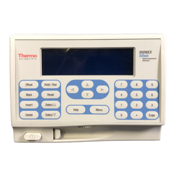
2 • Description Front Control Panel The control panel on the front door of the Dionex ED50A contains the liquid crystal display (LCD), the membrane keypad, and the actuator for the main power switch. The electronics chassis, described in Section 2.3, is located behind the front door. -
Page 18: Control Panel Keypad
Figure 2-1. Dionex ED50A Front Panel 2.1.2 Control Panel Keypad Use the keypad to directly control Dionex ED50A operation, as well as to create and modify programmed series of timed events, called methods. In summary: • Press to display a list of available screens. - Page 19 The time is removed and the help line prompts you to press Delete again to delete the step. Press Delete again. Or, to restore the original time and step parameters, press any button except Delete. Table 2-1. Dionex ED50A Control Panel Button Functions Doc. 065551-01 6/13...
- Page 20 When the method clock is in Run, pressing Hold/Run stops the method clock, thereby “holding” the method and freezing the current conditions. If the Dionex ED50A is in Voltammetry mode, pressing Hold/Run runs or holds the waveform program. Reset Changes the method clock time to...
-
Page 21: Rear Panel
Enter opens the highlighted screen. Table 2-1. Dionex ED50A Control Panel Button Functions (Continued) Rear Panel The Dionex ED50A rear panel (see Figure 2-2) contains fuses, connectors for line power, and a connection for the optional DX-LAN interface. Power Entry The power entry, fusing, and EMI filter are mounted on the rear of the 45 W power supply module. - Page 22 DX-LAN Connection (Optional) When you order the DX-LAN network, a DX-LAN connector is factory-installed in the upper left corner of the Dionex ED50A rear panel (see Figure B-1 in Appendix B). See Appendix Bfor DX-LAN interface installation instructions. Doc. 065551-01 6/13...
-
Page 23: Electronics Chassis
They may also be passed through slots at the front of the detector. Cables exit the Dionex ED50A through an opening in the rear panel (see Figure B-1). -
Page 24: Connectors
See Appendix D for a description of relay and TTL functions and the connections between the Dionex ED50A and other modules. 60-pin Ribbon Connector (Slot 5) The 60-pin ribbon cable to the Dionex ED50A front panel (display and keypad) connects here. Doc. 065551-01 6/13... -
Page 25: Cards
Relay I/O cards. • The CPU card provides control and monitoring of the other modules. A 60-pin ribbon cable assembly links the logic to the Dionex ED50A front panel display and keypad. • The Relay I/O card provides two isolated low voltage relay outputs, two TTL outputs, and four TTL inputs. -
Page 26: Amperometry Cell
A red or yellow LED indicates a fault. If a fault occurs, the Dionex ED50A enters its diagnostic state and no other control is permitted until the fault is corrected. Turn off the power to the Dionex ED50A for a few seconds and then turn it on again. If the power fault remains, contact Technical Support for Dionex products. - Page 27 Ag/AgCl and pH–Ag/AgCl. See Section 2.4.1 for details. Cell Design The Dionex ED50A amperometry cell is a thin-layer design. Mobile phase flows in a thin channel parallel to the surface of a flat disk electrode. The resulting smooth flow minimizes noise. The low volume (0.2 ...
-
Page 28: Combination Ph-Ag/Agcl Reference Electrode
PTFE substrate and PTFE gaskets are used. Adding a Second Detector The Dionex ED50A amperometry cell is installed directly after the column (a suppressor is generally not used). A second detector can be installed in-line with the amperometry cell, as long as the pressure at the amperometry cell inlet remains less than 700 kPa (100 psi). -
Page 29: Monitoring The Amperometry Cell Ph Readout
2 • Description especially true for metal oxide formation and reduction reactions. Because the reference potential of the combination pH–Ag/AgCl electrode also shifts by -0.059 V per pH unit, pH-dependent potential shifts at the working electrode are canceled. At a mobile phase pH of 7, the reference potential of the entire electrode is the same as that of the Ag/AgCl half-cell. -
Page 30: Functional Description
Operating and Control Modes The operating mode determines how the Dionex ED50A receives operating commands: • In Local mode, the Dionex ED50A receives commands from the front control panel buttons and screens. • In Locked Remote mode, Chromeleon 6.8 software sends commands from the host computer via the DX-LAN interface. -
Page 31: Local And Remote Modes
2.5.2 Local and Remote Modes Local Mode When the Dionex ED50A is powered up, it is always in Local mode. In Local mode, the detector accepts operating commands from two sources: • Direct input from the front panel keypad and screens. All operating functions are available with direct input. -
Page 32: Ttl Input Control
• OFFSET • HOLD/RUN • SUPPRESSOR OFF/ON • METHOD NUMBER INCRement • METHOD NUMBER DECRement • MARK Recorder • Increase RANGEX10 The Dionex ED50A accepts TTL signals when it is in Local or Remote mode. 2-16 Doc. 065551-01 6/13... -
Page 33: Operation And Maintenance
• Verify that the Dionex ED50A power cord is plugged into the main power. • Press the power switch actuator on the Dionex ED50A front panel to turn on the power (see Figure 2-1). • Verify that the Dionex ED50A passed all of its power-up tests (see Section 3.2). -
Page 34: Initial Screens
Each time the Dionex ED50A power is turned on, the screen is POWER-UP displayed. The revision codes on the screen identify the Moduleware POWER-UP and BIOS, in the event that service is ever needed. If the Dionex ED50A is Doc. 065551-01 6/13... - Page 35 Press any key to display the screen (see DIAGNOSTIC TESTS Section C.2.7) and learn which test failed. If the Dionex ED50A passes all the tests, the display automatically changes from screen to the screen. The screen shows active data in...
-
Page 36: Selecting The Control Mode
Dionex ED50A Electrochemical Detector Selecting the Control Mode To select the control mode from the front panel: 1. Go to the screen. MAIN STATUS DETAIL STATUS 2. To select the control mode, position the cursor in the control mode field (see Figure 3-3) and press Select ... -
Page 37: Running Under Method Control (Local Mode)
Running Under Method Control (Local Mode) In the Method control mode, a series of programmed timed events, known as a method, controls the Dionex ED50A. Methods are retained in memory even when the detector power is turned off. The detection mode determines which parameters can be controlled by a method. -
Page 38: Changing The Running Method
Dionex ED50A Electrochemical Detector 3.5.2 Changing the Running Method To stop the method that is currently running and run a different method, enter the new method number in the field on the screen and METHOD press . The new method will begin running, using the parameters Enter specified in the step for the current elapsed time. - Page 39 3 • Operation and Maintenance the value selected for the parameter in the preceding step. RUN 25 METHOD I AMP EDIT SAVE TO TTL RLY RANGE TIME WAVE OFFSET MARK 2 1 2 INIT 200 uC 0.00 2.00 4.00 Help Message Figure 3-4.
-
Page 40: Editing An Existing Method
Changing Method Parameters Move the cursor to the parameter field and enter a new value, using the Dionex ED50A front panel buttons. Press or a cursor arrow button Enter after each editing change. -
Page 41: Waveforms
3 • Operation and Maintenance Deleting a Method Step Move the cursor on the screen to the time of the step to be METHOD deleted and press twice. Delete Deleting an Entire Method Move the cursor on the screen to the field and press Delete METHOD... - Page 42 Dionex ED50A Electrochemical Detector Step 3 Step 4 0.7 V Potential (Volts) Integration 0.1 V Step 0 Step 1 Step 2 -0.1 V Step 5 Step 6 Time (sec) Step Time Potential Integrate 0.00 0.10 0.20 0.10 Begin 0.40 0.10 0.41...
-
Page 43: Cyclic Voltammetry
Voltammetry is similar to Integrated Amperometry in that a repeating potential vs. time waveform is applied to the cell. It differs in that the Dionex ED50A output is the cell current, which is continuously monitored and reported as in DC Amperometry. - Page 44 Keep the Hold/Run X/Y plotter pen in standby at first. Adjust the Y range settings on the XY plotter according to the Dionex ED50A readout. Readjust the Range setting on the screen, if necessary. Adjust the X range...
-
Page 45: Programming The Voltammetry Waveform
10 ms. (The slowest scan rate is therefore 1 mV per 10 ms, or 0.1 V/s.) If the potential you enter results in a noninteger change, the Dionex ED50A will substitute the closest acceptable potential. You may want to use the Select ... -
Page 46: Running The Waveform
28 s. 3.7.3 Running the Waveform When the cell is turned on, the Dionex ED50A applies the initial potential programmed at time zero. At that point, you may do any of the following: • To begin the waveform, press •... -
Page 47: Routine Maintenance
Periodically check liquid line connections to the cells (inside the chromatography module) for leaks and clean up any spills. The Dionex ED50A amperometry cells are designed to require minimal maintenance. If you observe the following precautions, the working electrode should rarely require polishing. -
Page 48: Shutdown
Dionex ED50A Electrochemical Detector • Do not allow the reference electrode to dry out. Make sure that mobile phase is always being pumped through the cell. If the cell will not be used for a short time (less than 2 days), disconnect the tubing from the inlet and outlet fittings and install fitting plugs. -
Page 49: Troubleshooting
4 • Troubleshooting This chapter is a guide to troubleshooting problems that may occur while operating the Dionex ED50A Electrochemical Detector. Turn to the section that best describes the operating problem. There, the possible causes of the problem are listed in order of probability, along with the recommended courses of action. -
Page 50: Low Detector Output
High Detector Output • Auto offset not activated recently Press on the Dionex ED50A front panel before making an injection. Offset • (Integrated Amperometry mode)—Excessive number of integration periods and/or incorrect potential for the integration Verify that the length and potential of the integration period is correct (refer to the column manual for the settings required for your application). -
Page 51: Noisy Or Drifting Baseline
4 • Troubleshooting Noisy or Drifting Baseline • Flow system leak ahead of cell; erratic baseline Check all fittings and liquid lines for leaks. Tighten or, if necessary, replace all liquid line connections. If the connections are made with ferrule fittings, first refer to Installation of Dionex Ferrule Fittings for tightening requirements. -
Page 52: Tailing Peaks
Dionex ED50A Electrochemical Detector • (DC Amperometry and Integrated Amperometry modes)—Regular baseline oscillation on high-sensitivity ranges Reconnect the short length of titanium tubing to the cell inlet. • (DC Amperometry and Integrated Amperometry modes)—Dirty or pitted working electrode If a disposable working electrode is being used, replace it. If the working electrode is non-disposable, polish it (see Section 5.2). -
Page 53: Cannot Set Amperometry Cell Ph Readout To 7.0
4 • Troubleshooting 3. Verify that the white working electrode lead is connected to junction J1 and the reference electrode cable is connected to J2. Look for salt on the cell pre-amp board. If salt is present, brush it off with a clean dry brush and then spray with a quick drying solvent to dissolve the remaining salt. -
Page 54: Discolored Ph Reference Electrode
Dionex ED50A Electrochemical Detector • Uncalibrated reference electrode Calibrate the reference electrode from the screen (see pH CALIBRATION Section 5.4). • Contaminated reference electrode Soak the reference electrode in a solution containing 1 M KCl and 1 M HCl. Replace the electrode (P/N 046333) (see Section B.5 for instructions). -
Page 55: Shift In Ag/Agcl Reference Potential
1M KCl plus 1M HCl. If this does not reduce the potential shift, replace the electrode. Using the Dionex ED50A Electronics If you do not have a digital voltmeter, follow this procedure: 1. Turn off the cell. -
Page 56: Faulty Dx-Lan Communication
Dionex ED50A Electrochemical Detector 5. Connect the reference electrode being tested to J2 by turning the electrode at right angles and plugging the center connector of the three-connector socket into the pin labeled “pH.” 6. Connect the new reference electrode to J2 by turning the electrode at right angles and plugging the center connector of the three-connector socket into the pin labeled “Ag.”... - Page 57 NOTE Before running the Dionex ED50A diagnostics, use the troubleshooting information in this chapter to isolate problems not related to the electronics. The Dionex ED50A Moduleware includes several diagnostic tests of the electronics. To access these, select the from the...
- Page 58 Dionex ED50A Electrochemical Detector 4-10 Doc. 065551-01 6/13...
-
Page 59: Service
Dionex Terms and Conditions. Eliminating Liquid Leaks The PEEK version of the Dionex ED50A is plumbed with 1.60-mm (1/16-in) PEEK tubing, Dionex ferrule fittings (P/N 043276), and 10-32 fitting bolts (P/N 043275). For tightening requirements, see Installation of Dionex Ferrule Fittings. -
Page 60: Polishing The Amperometry Cell Working Electrode
Dionex ED50A Electrochemical Detector Polishing the Amperometry Cell Working Electrode NOTE These instructions are for non-disposable working electrodes only. Do not polish disposable electrodes; they are designed to be easily replaced when necessary. Polish carbohydrate gold (P/N 044112), platinum, silver, and glassy carbon working electrodes before initial installation in the amperometry cell (see the steps below). - Page 61 5 • Service pad is shipped with each type of working electrode. Using indelible ink, label each pad to indicate the working electrode with which it is used. Cell Cover Assembled Cell Cell Body Working Electrode Alignment Studs Cell Gasket Wing Screws Figure 5-1.
-
Page 62: Replacing The Ph Reference Electrode O-Ring
Dionex ED50A Electrochemical Detector electrode block. Carefully wipe the surface of the block with a soft damp cloth or tissue. 9. If you used the coarse polishing compound in Step 5, repeat Steps 5 through 7 with the fine compound. - Page 63 5 • Service Reference Electrode Cylinder Junction J2 Cell Body Figure 5-2. Removing the Reference Electrode 5. While maintaining all parts in a vertical orientation, lift the reference electrode straight up and out of the cell body. 6. Remove the old reference electrode O-ring by sliding it off the end of the glass body of the reference electrode.
- Page 64 Dionex ED50A Electrochemical Detector Figure 5-4. Identifying the CHEMRAZ O-Ring 8. Rinse and dry the reference electrode cavity to remove any particulate matter such as salt crystals. 9. Verify that the stop ring (P/N 045967) is in place at the bottom of the reference electrode cavity (see Figure 5-5).
- Page 65 5 • Service 11. Before reinstalling the electrode, observe the inside of the reference electrode cavity. When installed correctly, the electrode fits into the narrower diameter area at the bottom of the cavity and sits on top of the stop ring. 12.
-
Page 66: Calibrating The Reference Electrode
Dionex ED50A Electrochemical Detector Junction J1 Junction J2 Figure 5-7. Reference Electrode Electronics Card Junctions J1 and J2 13. Slide the cell cover back over the cell body, making sure that the cable connector on the end of the electronics card lines up with the opening in the cell cover. - Page 67 5 • Service Reference Electrode Cylinder Junction J2 Figure 5-8. Removing the Reference Electrode 7. While maintaining all parts in a vertical orientation, lift the reference electrode with the cylinder straight up and out of the cell body. 8. Rinse the reference electrode thoroughly in deionized water to remove any precipitated salt.
-
Page 68: Replacing The Main Power Fuses
Reconnect the cell’s inlet and outlet lines and the electrical cable. Replacing the Main Power Fuses The fuse holder is in the main power receptacle on the Dionex ED50A rear panel. 1. Turn off the main power. HIGH VOLTAGE—Disconnect the main power cord from its source and also from the rear panel of the Dionex ED50A. - Page 69 5 • Service 2. A recessed lock is located on each side of the fuse holder (see Figure 5-10). Using a small screwdriver, push each lock toward the center to release it. The fuse holder pops out slightly when the locks release. When both locks are released, pull the fuse holder straight out of its compartment.
- Page 70 Dionex ED50A Electrochemical Detector 5-12 Doc. 065551-01 6/13...
-
Page 71: Physical
A • Specifications A.1 Physical Dimensions 22.5 cm W x 17.0 cm H x 42.0 cm D (8.8 in W x 6.6 in H x 16.4 in D) 6 cm (2.4 in) clearance required behind the detector Weight 8.2 kg (18 lb) Decibel Level 50 db (“A WEIGHING”... -
Page 72: Detector
Control of four functions via TTL or Relay contacts Operation DX-LAN All functions can be controlled by Chromeleon 6.8 software on a Operation PC connected to the Dionex ED50A via the DX-LAN interface (Optional) A.6 Amperometry Cell Cell Body Titanium (counterelectrode) ~ 0.2 L... -
Page 73: B • Installation
B.2 Power Connection The power to the Dionex ED50A is controlled from the main power switch on the Dionex ED50A rear panel. The power supply is auto-sensing; thus, no adjustment is required to select the line voltage. -
Page 74: Overview Of Dx-Lan Interface Connections (Optional
B.3 Overview of DX-LAN Interface Connections (Optional) When you order the DX-LAN network, a DX-LAN connector is factory-installed in the upper left corner of the Dionex ED50A rear panel (see Figure B-1). The DX-LAN interface provides communication between the Dionex ED50A and a host computer running Chromeleon 6.8 software. -
Page 75: Dx-Lan Interface Connections (Optional
B • Installation consists of a detector interface card, installed in the Dionex ED50A; a computer interface card, installed in the host computer; and cabling between the two cards. The DX-LAN interface uses a 10BASE-T RJ-45 (telephone-style) connector. To install the 10BASE-T cable, see Section B.4. -
Page 76: Installing The Dx-Lan Cable
See the example in Figure B-2. 3. Connect the other end of the cable into the 10BASE-T DX-LAN connector on the Dionex ED50A rear panel (see Figure B-1). 4. Connect a 10BASE-T cable from a 10BASE-T port on the hub to the 10BASE-T port on the host computer’s internal DX-LAN card. -
Page 77: Amperometry Cell Installation
B • Installation B.5 Amperometry Cell Installation B.5.1 Preparing the Cell Gasket and Working Electrode Follow these instructions if you are installing a standard (non-disposable electrode). To install a disposable working electrode, refer to the installation manual shipped with the electrode. NOTE To avoid electrode fouling, always wear gloves when handling electrodes. -
Page 78: Preparing The Reference Electrode
Dionex ED50A Electrochemical Detector 4. For carbohydrate gold (P/N 044112), platinum, silver, and glassy carbon working electrodes only: Polish the working electrode block (see Section 5.2) and rinse its surface with deionized water. Wipe it with a damp, soft cloth or tissue. -
Page 79: Calibrating The Reference Electrode
B • Installation 2. Remove the reference electrode from its box. Remove the electrode from the storage bottle by partially unscrewing the cap and pulling the electrode out of the opening in the cap. Save the bottle and cap. Always store the electrode in the storage bottle filled with saturated KCl solution when the cell is not in use. -
Page 80: Installing The Reference Electrode
Dionex ED50A Electrochemical Detector 5. Press , and and following the instructions on the Menu screen to calibrate the pH reference electrode. CALIBRATION 6. After calibration, turn off the detector and disconnect the cables. B.5.4 Installing the Reference Electrode 1. Remove the O-ring retainer from the reference electrode cavity (see Figure B-6). - Page 81 B • Installation 3. Verify that you have all of the parts shown in Figure B-8. Figure B-8. Reference Electrode Parts NOTE The O-ring inside the electrode storage bottle cap and the CHEMRAZ O-ring are made from different materials. To prevent leaks, use only the CHEMRAZ O-ring (see Figure B-9).
- Page 82 Dionex ED50A Electrochemical Detector 4. Pull the J2 connector through the opening in the electrode cylinder (see Figure B-10). J2 Connector Figure B-10. Installing the Electrode Cylinder 5. Slide the PEEK O-ring retainer and CHEMRAZ O-ring onto the electrode (see Figure B-11).
- Page 83 B • Installation 7. Make sure the reference electrode is centered in the reference electrode cavity and then carefully insert the electrode until it touches the stop ring at the bottom of the cavity (see Figure B-12). Make sure electrode is all the way down inside the cavity and not “hung up”...
-
Page 84: Connecting The Amperometry Cell Cable
Dionex ED50A Electrochemical Detector B.5.5 Connecting the Amperometry Cell Cable 1. Make sure the detector is turned off. 2. Connect the amperometry cell cable to the amperometry cell. 3. Mount the cell in the chromatography module or outside the module on the amperometry cell bracket (P/N 048749). -
Page 85: Plumbing The Amperometry Cell
B • Installation B.5.6 Plumbing the Amperometry Cell Install the Dionex ED50A amperometry cell directly after the column. Figure B-15 shows the plumbing schematic for amperometry detection. A second detector can be installed before the amperometry cell. However, if a second detector is installed after the cell, make sure the pressure at the amperometry cell outlet remains below 700 kPa (100 psi). -
Page 86: Recorder/Diagnostic Connection
(30 to 40 psi) of backpressure. B.6 Recorder/Diagnostic Connection Connecting a strip chart recorder or integrator to the Dionex ED50A allows you to record or monitor several parameters, in addition to the cell analog output. For a list of the pinouts for the cable, see Appendix F. - Page 87 C • User Interface This appendix describes all of the screens available for display on the front panel of the Dionex ED50A Electrochemical Detector. There are two categories of screens: operational and diagnostic (see Figure C-1). • Operational screens enable you to create, edit, and run methods that control Dionex ED50A operation, and to select default parameters for the detector.
-
Page 88: Operational Screens
Dionex ED50A Electrochemical Detector C.1 Operational Screens NOTE Dionex ED50A detectors shipped in June 2013 or later are not recommended for conductivity detection. Therefore, operational screens for the Conductivity mode are not described in this manual. C.1.1 Menu of Screens—Integrated Amperometry... -
Page 89: Main Screen-Integrated Amperometry
C • User Interface C.1.2 Main Screen—Integrated Amperometry screen displays the measured charge (coulombs) and other MAIN primary functions in large characters that make viewing easier from a distance. INT AMPEROMETRY WAVEFORM CELL - 4.36 RANGE 1000 nC LOCAL METHOD 134.56 MIN Help Message Figure C-3. - Page 90 Dionex ED50A Electrochemical Detector Screen Field Description Sets the detector sensitivity between 50 pC and 200 C. RANGE Control Mode Sets the detector to Local, Remote, or Locked Remote control. METHOD Sets the method number. Pressing Select and Enter sets the detector to Direct control.
-
Page 91: Detail Screen-Integrated Amperometry
C • User Interface C.1.3 Detail Screen—Integrated Amperometry screen includes all the fields contained on the screen, as DETAIL MAIN well as the TTL and Relay fields and other fields to control detection. Refer to the screen for a description of fields common to both MAIN screens. -
Page 92: Method-Integrated Amperometry
Dionex ED50A Electrochemical Detector C.1.4 Method—Integrated Amperometry A method consists of a series of timed steps. Each step has a set of parameters associated with it. Initial conditions are applied when a method is invoked. A lower case next to the last step on the display indicates that the method contains more steps. - Page 93 C • User Interface Screen Field Description OFFSET Stores the offset value. The baseline is set by subtracting the offset measured when this step executes from all subsequent measurements. An asterisk (*) indicates that offset will occur at this time. MARK Sends a positive pulse to the analog output (recorder) as an event marker.
-
Page 94: Waveform-Integrated Amperometry
Dionex ED50A Electrochemical Detector C.1.5 Waveform—Integrated Amperometry Figure C-7 shows the screen for Integrated Amperometry. WAVEFORM These entries form points on a plot of potential vs. time. When the last step displayed is not the last step in the waveform, a lower case is displayed beside the time digits in the last line. -
Page 95: Menu Of Screens-Dc Amperometry
C • User Interface C.1.6 Menu of Screens—DC Amperometry Figure C-8 shows the for the DC Amperometry mode. MENU of SCREENS MENU of DC AMPEROMETRY SCREENS MODULE SETUP MAIN SCREEN ANALOG OUT SETUP DETAIL SCREEN METHOD TIME FUNCTION IN ---- DIAGNOSTIC MENU Help Message Figure C-8. -
Page 96: Main Screen-Dc Amperometry
Dionex ED50A Electrochemical Detector C.1.7 Main Screen—DC Amperometry screen displays the measured current (Amperes) and other MAIN primary functions in large characters that make viewing easier from a distance. DC AMPEROMETRY POTENTIAL 0.05 V CELL - 6. 13 RANGE 1000 nA... -
Page 97: Detail Screen-Dc Amperometry
C • User Interface C.1.8 Detail Screen—DC Amperometry screen includes all the fields contained on the screen, as DETAIL MAIN well as the TTL and Relay fields and other fields to control detection. Refer to the screen for a description of fields that are common to MAIN both screens. -
Page 98: Method-Dc Amperometry
Dionex ED50A Electrochemical Detector C.1.9 Method—DC Amperometry A method consists of a series of timed steps. Each step has a set of parameters associated with it. Initial conditions are applied when a method is invoked. A lower case next to the last step on the display indicates that the method contains more steps. - Page 99 C • User Interface Screen Field Description OFFSET Stores the offset value. The baseline is set by subtracting the offset measured when this step executes from all subsequent measurements. An asterisk (*) indicates that OFFSET will occur at this time. MARK Sends a positive pulse to the analog output (recorder) as an event marker.
-
Page 100: Menu Of Screens-Voltammetry
Dionex ED50A Electrochemical Detector C.1.10 Menu of Screens—Voltammetry Figure C-12 shows the for the Voltammetry mode. MENU of SCREENS MENU of VOLTAMMETRY SCREENS MODULE SETUP MAIN SCREEN ANALOG OUT SETUP DETAIL SCREEN ---- TIME FUNCTION IN WAVEFORM DIAGNOSTIC MENU Help Message Figure C-12. -
Page 101: Main Screen-Voltammetry
C • User Interface C.1.11 Main Screen—Voltammetry screen displays the measured current (Amperes) and other MAIN primary functions in large characters that make viewing easier from a distance. VOLTAMMETRY CELL - 6. 13 1000 nA RANGE LOCAL DIRECT CNTRL Help Message Figure C-13. -
Page 102: Detail Screen-Voltammetry
Dionex ED50A Electrochemical Detector C.1.12 Detail Screen—Voltammetry screen includes all the fields contained on the screen, as DETAIL MAIN well as the TTL and Relay fields and other fields to control detection. Refer to the screen for a description of fields that are common to MAIN both screens. -
Page 103: Waveform-Voltammetry
C • User Interface C.1.13 Waveform—Voltammetry Figure C-15 shows the screen for Voltammetry. These entries WAVEFORM form points on a plot of potential vs. time. When the last step displayed is not the last step in the waveform, a lower case is displayed beside the time digits in the last line. -
Page 104: Module Setup
Dionex ED50A Electrochemical Detector C.1.14 Module Setup The backlight intensity, key beep, and error beep are configured from the screen. MODULE SETUP MODULE SETUP DISPLAY PANEL BACKLIGHT: DIUM KEY ACTUATION SOUND: NTRY ERROR SOUND: HELP LANGUAGE: ENGLISH HEAT SOURCE: Help Message Figure C-16. -
Page 105: Analog Out Setup
C • User Interface C.1.15 Analog Out Setup screen contains parameters for setting the ANALOG OUT SETUP analog output, such as for a recorder or oscilloscope. ANALOG OUT SETUP OFFSET OUTPUT: ZERO POSITION: % FULL SCALE VOLTS FULL SCALE: RISE TIME: POLARITY: Help Message Figure C-17. -
Page 106: Time Function In
Dionex ED50A Electrochemical Detector C.1.16 Time Function In This screen displays the detector functions that can be controlled with TTL input from another device, and lets you assign any four of the functions to the four TTL inputs. The field selects the type of input MODE signal the detector will respond to. -
Page 107: Diagnostic Screens
KEYBOARD TEST 10 pH CALIBRATION Help Message Figure C-19. Diagnostic Menu Screen NOTE Dionex ED50A detectors shipped in June 2013 or later are not recommended for conductivity detection. Therefore, diagnostic screens for the Conductivity mode are not described in this manual. -
Page 108: Power-Up Screen
Dionex ED50A Electrochemical Detector C.2.2 Power-Up Screen This screen displays the revision numbers for the Moduleware and BIOS code. It also displays the identification number of the optional DX-LAN interface, if connected. ED50A ELECTROCHEMICAL DETECTOR MODULEWARE REV n.nn BIOS REV n.nn... -
Page 109: Elapsed Time
C • User Interface C.2.3 Elapsed Time This screen reports for how long various Dionex ED50A parameters have been in use. The status of each parameter is updated in real time. ELAPSED TIME RESET MODULE ON: nnnnnn hours BACKLIGHT: nnnnnn hours... -
Page 110: Analog Status
Dionex ED50A Electrochemical Detector C.2.4 Analog Status This screen reports the status of several analog test points. If a run is in progress, the status updates are from the last idle state. If no run is in progress, the values are in real time. -
Page 111: Dx-Lan Status
C • User Interface C.2.5 DX-LAN Status The DX-LAN driver monitors several types of errors that may occur on the network. The detector reads the DX-LAN error counts and displays them on this screen, along with the DX-LAN addresses. Most errors are caused by a defective cable, missing cable, or incorrectly terminated cable. -
Page 112: Keyboard Test
RETRY C.2.6 Keyboard Test You can conduct an interactive test of the Dionex ED50A front panel keypad from this screen. Pressing any front panel button changes the corresponding button indicator on the screen to reverse video. This confirms proper operation of that button. When you release the button, the display returns to normal video. -
Page 113: Diagnostic Tests
C • User Interface C.2.7 Diagnostic Tests These tests verify the integrity of the detector electronics and functions. DIAGNOSTIC TESTS CELL: INT NOISE TEST: DAC RAMP: SCOPE TEST: RDY CELL DRIVE POWER P AES/SRS LEAK > Help Message Figure C-25. Diagnostic Tests Screen Screen Field Description Specifies whether the cell to be tested is internal (INT) or external... - Page 114 Dionex ED50A Electrochemical Detector Screen Field Description — Tests the EC Drive DAC. A full-scale ramp is repeated over and over until you exit the test or the screen. Disconnect the amperometry cell before running this test. SCOPE TEST Generates test waveforms that can be monitored on test points on the SCR and SP cards, using an oscilloscope or chart recorder.
-
Page 115: Leak Sensor Calibration And Status
Checks the detector's leak sensor for a correct, open circuit, or short circuit condition. C.2.8 Leak Sensor Calibration and Status Dionex ED50A detectors shipped in June 2013 or later are not recommended for conductivity detection. Therefore, operational screens for the Conductivity mode are not described in this manual. C-29... -
Page 116: Signal Statistics
Dionex ED50A Electrochemical Detector C.2.9 Signal Statistics This screen enables you to monitor the selected input to the A/D circuitry. When the screen is first displayed, the status values are equal to the value, and reads 0. Status values are... -
Page 117: Calibrate Conductivity Cell
C • User Interface C.2.10 Calibrate Conductivity Cell Dionex ED50A detectors shipped in June 2013 or later are not recommended for conductivity detection. Therefore, operational screens for the Conductivity mode are not described in this manual. C.2.11 pH Calibration This screen allows you to calibrate the pH reference electrode in the amperometry cell. - Page 118 Dionex ED50A Electrochemical Detector Screen Field Description SELECT CAL indicates no selection has been made. Calibration will not and press Enter to calibrate the electrode for pH occur. Select 7.0. 2nd BUFFER Enter the known pH of the second buffer solution. With the reference electrode in the second buffer solution, press Enter to perform the second calibration.
-
Page 119: D • Ttl And Relay Control
D • TTL and Relay Control The strip of eight 2-pin connectors on the Dionex ED50A electronics chassis provides two relay outputs, two TTL outputs, and four TTL inputs (see Figure D-1). • Connect the outputs to the TTL or relay inputs of a device to control functions in the connected device. -
Page 120: Ttl And Relay Connections
1. Twisted pairs of wires (P/N 043598) and 2-pin connector plugs (P/N 921019) are provided in the Dionex ED50A Ship Kit. Attach a 2-pin plug to each end of the twisted pair of wires to be connected. The signal wire goes on the top of each plug;... -
Page 121: Ttl And Relay Output Operation
D • TTL and Relay Control D.2 TTL and Relay Output Operation The Dionex ED50A provides two TTL outputs and two relay contacts for control of functions in external devices such as an integrator, autosampler, or another Thermo Scientific module. -
Page 122: Ttl Input Operation
The minimum pulse width guaranteed to be detected is 50 ms. The maximum pulse width guaranteed to be ignored as noise or invalid is 4 ms. The action of the Dionex ED50A is undefined for pulses less than 50 ms or greater than 4 ms. - Page 123 D • TTL and Relay Control • Inverted Pulse: The inverted pulse mode operates identically to the normal pulse mode, except that the positive and negative edges are reversed in function. Figure D-4. TTL and Relay Input Signal Modes Doc. 065551-01 6/13...
-
Page 124: Ttl Input Functions
Dionex ED50A Electrochemical Detector D.3.2 TTL Input Functions The four TTL inputs can be connected to devices capable of providing TTL output signals. Signals from the connected devices can control up to four of the functions listed in the table below. Use the... -
Page 125: E • Signal Processor Functions
E • Signal Processor Functions Table E-1 lists the functions of the Signal Processor (SP) card. Function DC Amp. Int. Amp. Volt. 5 mS noise filter DC amplifier 100 mS filter Bipolar cell drive analog-to-digital filter Amperometry cell drive smoothing filter pH slope and offset corrector Cell receiver/driver Fine and coarse integrators... - Page 126 Dionex ED50A Electrochemical Detector Doc. 065551-01 6/13...
-
Page 127: F • Connector Pinouts
F • Connector Pinouts Recorder/Diagnostic Signal Pinouts This section describes the Recorder/Diagnostic Signal pinouts. The connector is supplied plugged into the socket. The pins are numbered consecutively from 1 to 10 (top to bottom). Signal Recorder Negative Recorder Positive Suppressor Supply Voltage Dionex DS3 Supply Current Conductivity Cell Flow Stream Temperature Amperometry Cell Flow Stream pH... -
Page 128: Signal Electrical Parameters
Dionex ED50A Electrochemical Detector F.1.1 Signal Electrical Parameters Pin 1 Attach the negative input of the chart recorder to pin 1. Pin 2 Select the full-scale output range setting (0 to 0.01 V, 0 to 0.1 V, or 0 to 1.0 V) on the... - Page 129 F • Connector Pinouts Volts -0.7 -0.6 -0.5 -0.4 -0.3 -0.2 -0.1 Table F-2. Amperometry Cell Flow Stream Temperatures Doc. 065551-01 6/13...
-
Page 130: Ttl/Relay Pinouts
Dionex ED50A Electrochemical Detector TTL/Relay Pinouts The TTL and Relay connectors are on the DX-LAN/Relay card. The TTL and Relay connectors all have the same pinout configuration; be careful to use the correct connector. Connector Number Pin Number Description 1 and 2... -
Page 131: Amperometry Cell Connector Pinouts-Sp
F • Connector Pinouts Amperometry Cell Connector Pinouts—SP The amperometry cell connects to the SP card. The amperometry cell connector is a single-row, shielded BERG-type latching connector. With the connector on the cable facing you and the open metal shield on the left, pin 1 is at the top. Pin Number Description Color (inside cable) - Page 132 Dionex ED50A Electrochemical Detector Doc. 065551-01 6/13...
-
Page 133: G • Reordering Information
G • Reordering Information Part Number Item Quantity 065038 Amperometry cell 060082 AAA-Direct disposable gold working electrode 6, with 2 gaskets (2.0 mil) 060140 AAA-Direct disposable gold working electrode 4 pkgs. of 6, with 8 gaskets (2.0 mil) 060139 Carbohydrate disposable gold working electrode 6, with 2 gaskets (2.0 mil) 060216... - Page 134 Dionex ED50A Electrochemical Detector Part Number Item Quantity 043276 Dionex ferrule fittings 043275 Fitting bolts, 10-32 042690 Tubing, 0.25-mm (0.010-in) ID (for cell inlet Varies with connection) installation site 043598 Twisted black-and-red wires (for recorder/diagnostic and TTL/Relay connections) 921019 TTL connector plugs (green) 954745 Fuse, 3.15 amp (fast-blow IEC127, type 1)
- Page 135 Index Numerics Analog output range Full-scale output, A-1 10BASE-T cable installation, B-4 Analog Status screen, C-24 10BASE-T DX-LAN interface installation, B-4 Analog test points, C-24 Arrow buttons, 2-4 AutoTrace 280 Declaration of Conformity, 1-6 Model data label, 1-6 Aborting a running method, 2-4 Absorbance detection, 1-1 Ag/AgCl half-cell, 2-12 Amperometry, 1-2...
- Page 136 Dionex ED50A Electrochemical Detector Clock Detector specifications, A-2 See Method clock Diagnostic Menu, 2-5, C-1, C-21 Computer control, 1-2, 2-15 Diagnostic tests, C-27 Conductivity cell Diagnostics, 4-9 Calibration, C-31 Accessing, C-21 Noise test, C-27 Direct control mode, 2-14, 3-4 Connectors...
- Page 137 Index Elapsed Time screen, C-23 Electrochemical cell Glassy carbon electrodes, 2-10 See Amperometry cell Gold electrodes, 2-10 Electrochemical detection Molecules detected by, 1-1 Electrodes, 2-10–2-11 Electronics, 2-7 Repair procedures, 5-1 Half-cells, 2-12 Testing, C-27 High detector output, 4-2 Electronics cards, 2-9 Hold/Run See also Names of cards Front panel button, 2-4...
- Page 138 Dionex ED50A Electrochemical Detector Method clock Controlling with TTL input, D-6 Keypad, 2-1–2-2 Elapsed time, 3-5 Description, 2-3–2-5 Starting, 2-4 Testing, C-26 Stopping, 2-4 Method control mode, 2-14, 3-5 Changing parameters, 3-6 Method screen DC Amperometry mode, C-12 LCD backlight...
- Page 139 Index Module setup, C-18 PEEK tubing, 5-1 Moduleware, 2-9, 4-9 pH half-cell, 2-12 Revision number, 3-2, C-22 pH reading, C-11, C-16 Always 7.0, 4-4 Cannot be set to 7.0, 4-5 Nonexistent, 4-5 pH reference electrode Network See Reference electrode See DX-LAN network Platinum electrodes, 2-10 No detector response, 4-1 Polarity...
- Page 140 Dionex ED50A Electrochemical Detector Voltammetry, C-15 Safety Rear panel Messages and icons, 1-4 DX-LAN cable installation, B-4 Safety icons, 1-4–1-5 Rear panel description, 2-5 Safety labels, 1-7 Recorders Saving Analog output setting, C-19 Methods, 3-7, 3-9 Connections, 3-11 SCR card, 2-9...
- Page 141 Index Suppressor Input signal modes, D-4 Controlling with TTL input, D-6 Installation, D-2 Installation verification, C-24 Output operation, D-2 Temperature setting, C-24 Time Function In screen, C-20 Voltage range setting, C-24 TUV, 1-7 Symbols, 1-7 Video, normal, 2-1 Technical Support for Dionex products, 4-1 Video, reverse, 2-1 Temperature, operating, A-1 Voltage...
- Page 142 Dionex ED50A Electrochemical Detector Zero position, C-19 Index-8 Doc. 065551-01 6/13...
Need help?
Do you have a question about the Dionex ED50A and is the answer not in the manual?
Questions and answers