
Subscribe to Our Youtube Channel
Related Manuals for Thermo Scientific ECD Upgrade Kit


Summary of Contents for Thermo Scientific ECD Upgrade Kit
- Page 1 Thermo Scientific ECD Upgrade Kit Per TRACE™ GC Ultra Installation Guide PN 317 093 35, Revision April 2009 Home...
- Page 2 ECD Upgrade Kit for TRACE™ GC - Ultra Installation Guide April 2009 Edition Part Number 317 093 35 © 2007-2009 Thermo Fisher Scientific Inc. All rights reserved. Printed in ITALY. Published by Thermo Fisher Scientific S.p.A. Technical Publications, Strada Rivoltana 20090 Rodano - Milan...
-
Page 3: Table Of Contents
Reinstall the GC Panels ................. 15 Restarting the GC................... 15 Configuration ........................... 16 Set ECD Parameters......................... 17 Operating Sequences Installing ECD Upgrade Kit ......................8 Configuring Detector and Make-up Gas ................... 16 Parameters Setting ..........................17 Figures The TRACE GC Ultra ........................8 TRACE GC Ultra Top Cover ...................... - Page 4 Contents Installation Guide...
-
Page 5: Electron Capture Detector
Detector on your TRACE GC Ultra. Guide at a Glance… About This Guide ....................6 Introduction ......................6 Getting Started......................7 Configuration......................16 Set ECD Parameters .....................17 Operating Sequences Installing ECD Upgrade Kit ...................8 Configuring Detector and Make-up Gas ..............16 Parameters Setting ....................17 Installation Guide... -
Page 6: About This Guide
Upgrade Kit Electron Capture Detector About This Guide About This Guide It provides the instructions to install and configure the Electron Capture Detector on your TRACE GC Ultra. WARNING! The Electron Capture Detector (ECD) contains a Ni beta-emitting radioactive source of 370 MBq. NOTE For Conventions, Symbols, Safety Information, Wipe Test and Costumer Communications, please refer to the TRACE GC Ultra Operating Manual. -
Page 7: Getting Started
Operating Manual. Getting Started This paragraph contains the instruction to install the ECD on your GC. To properly install the ECD upgrade kit, the following sequential operations must be performed: • Remove the top and right side panels of the GC. -
Page 8: Removing The Gc Panels
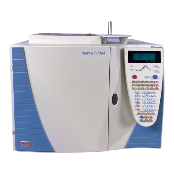
5. Disconnect the main power cable from the rear of the GC. OPERATING SEQUENCE Installing ECD Upgrade Kit Follow this instruction to properly install the ECD Upgrade Kit. Figure 1-1. The TRACE GC Ultra Removing the GC Panels This operation allows to access the GC upper parts and the electronic compartment. -
Page 9: Trace Gc Ultra Top Cover
Upgrade Kit Getting Started Electron Capture Detector Material needed: • 2-mm Allen wrench • 3-mm Allen wrench Remove the GC Top Cover 1. Lift the detector cover off the GC top cover. 2. Open the oven door and unscrew the two top cover fastening screws. 3. -
Page 10: Trace Gc Ultra Rear Panel
Upgrade Kit Electron Capture Detector Getting Started 3. Hold the side panel parallel to the GC, and pull the lower edge of the panel away from the GC. 1. Right Panel Securing Screw Figure 1-3. TRACE GC Ultra Rear Panel Installation Guide... -
Page 11: Installing The Ecd Control Card
Upgrade Kit Getting Started Electron Capture Detector Installing the ECD Control Card The ECD control card must be installed into the proper expansion slot marked A, B or C located on the left part of the GC mother board in the electronic compartment. -
Page 12: Detector Control Card Expansion Slots
Upgrade Kit Electron Capture Detector Getting Started 1. Detector control card expansion 2. Additional heat control jumpers Slots 3. Mother board Figure 1-5. Detector Control Card Expansion Slots 2. Verify that the jumper marked Jx, adjacent to the defined detector control card connector on the mother board, is positioned between the pins 1 and 2. - Page 13 Upgrade Kit Getting Started Electron Capture Detector Jumper Positioning Pins 1-2 = additional heat control enabled Pins 2-3 = additional heat control not enabled WARNING! The jumper marked “Jx” must be positioned between the pins 1 and 2. 3. Guide through the slot mentioned at point 1 the signal and excitation cables coming from the top of the card.
-
Page 14: Mounting The Ecd On The Gc
Upgrade Kit Electron Capture Detector Getting Started Mounting the ECD on the GC This operation allows the correct installation of the ECD on your TRACE GC Ultra. Refer to Figure 1-6. Material needed • ECD Fixing Tool 1. ECD 2. Detector Base Body 3. -
Page 15: Reinstall The Gc Panels
Upgrade Kit Getting Started Electron Capture Detector 2. Carefully, connect the signal, excitation and temperature sensor/heater extension cables coming from the detector control card, to the detector cell. Reinstall the GC Panels This operation allows to reinstall the GC panels Material needed: •... -
Page 16: Configuration
Upgrade Kit Electron Capture Detector Configuration Configuration This paragraph contains the instructions to configure your GC to operate with ECD. You configure the detector and make-up gas in the menu. Refer to CONFIGURE Chapter 16 of the TRACE GC Ultra Operating manual. OPERATING SEQUENCE Configuring Detector and Make-up Gas 1. -
Page 17: Set Ecd Parameters
Upgrade Kit Set ECD Parameters Electron Capture Detector Set ECD Parameters To set ECD parameters, it is necessary to open the ECD menu and the ECD Signal menu. • menu contains the detector control parameters. DETECTOR (ECD) To set parameters, refer to the Chapter 18 of the TRACE GC Ultra Operating Manual. - Page 18 Upgrade Kit Electron Capture Detector Set ECD Parameters 2. To open ECD Signal menu, press LEFT SIGNAL or RIGHT SIGNAL according to the location of the detector. The following menu is displayed: LEFT SIGNAL (ECD) Output (1000) Offset Auto zero? Y/N <...
Need help?
Do you have a question about the ECD Upgrade Kit and is the answer not in the manual?
Questions and answers