Sign In
Upload
Manuals
Brands
Juniper Manuals
Network Router
M-Series
Juniper M-Series Manuals
Manuals and User Guides for Juniper M-Series. We have
4
Juniper M-Series manuals available for free PDF download: Monitoring And Troubleshooting Manual, Manual, Configuration Manual, Datasheet
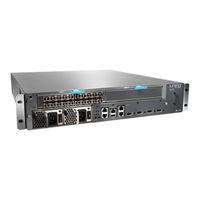
Juniper M-Series Monitoring And Troubleshooting Manual (812 pages)
Brand:
Juniper
| Category:
Network Router
| Size: 24.02 MB
Table of Contents
Series and T Series Routers
1
Table of Contents
3
About the Documentation
39
Junos Documentation and Release Notes
39
Objectives
39
Audience
40
Supported Routing Platforms
40
About the Documentation
41
Document Conventions
41
Table 1: Notice Icons
41
Table 2: Text and Syntax Conventions
41
Using the Index
41
Documentation Feedback
42
Requesting Technical Support
43
Self-Help Online Tools and Resources
43
Opening a Case with JTAC
43
Juniper Networks M Series and T Series Routers
45
M Series Multiservice Edge Routers
45
T Series Core Routers
45
Chapter 1 M Series Multiservice Edge Routers
47
M5 and M10 Internet Router Overview
48
Figure 1: M5 and M10 Routers
48
M5 and M10 Router Components
49
Table 3: M5 and M10 Router Major Hardware Components
49
M7I Multiservice Edge Router Overview
50
Figure 2: M7I Router
50
M7I Router Components
51
Table 4: M7I Router Major Hardware Components
51
M10I Multiservice Edge Router Overview
52
Figure 3: M10I Router
52
M10I Router Components
53
Table 5: M10I Router Major Hardware Components
53
M20 Internet Router Overview
54
M20 Router Components
55
Figure 4: M20 Router
55
Table 6: M20 Router Major Hardware Components
56
M40 Router Overview
57
Figure 5: M40 Router
57
M40 Router Components
58
Table 7: M40 Router Major Hardware Components
58
M40E Multiservice Edge Router Overview
59
Figure 6: M40E Router
59
M40E Router Major Hardware Components
60
Table 8: M40E Router Major Hardware Components
60
M120 Multiservice Edge Router Overview
61
Figure 7: Front View of an M120 Router
61
Figure 8: Rear View of an AC M120 Router
62
M120 Router Major Hardware Components
63
Figure 9: Rear View of a DC M120 Router
63
Table 9: M120 Router Major Hardware Components
63
M160 Internet Router Overview
65
Figure 10: M160 Router
65
M160 Router Major Hardware Components
66
Table 10: M160 Router Major Hardware Components
66
M320 Multiservice Edge Router Overview
67
M320 Router Major Hardware Components
68
Figure 11: M320 Router
68
Table 11: M320 Router Major Hardware Components
69
Chapter 2 T Series Core Routers
71
T320 Core Router Overview
71
Figure 12: Front View of the T320 Router
72
Figure 13: Rear View of the T320 Router
73
T Series Core Routers
73
T320 Router Major Hardware Components
74
Table 12: T320 Router Major Hardware Components
74
T640 Core Router Overview
75
Figure 14: T640 Router
76
T640 Router Major Hardware Components
77
Table 13: T640 Router Major Hardware Components
77
T1600 Core Router Overview
78
Figure 15: Front View of the T1600 Router
79
Figure 16: Rear View of the T1600 Router
80
T1600 Router Major Hardware Components
81
Table 14: T1600 Router Major Hardware Components
82
TX Matrix Router Overview
83
Figure 17: Front View of a TX Matrix Router
84
Figure 18: Rear View of a TX Matrix Router
85
TX Matrix Router Major Hardware Components
86
Table 15: TX Matrix Router Major Hardware Components
86
TX Matrix Plus Router Overview
87
Figure 19: Front View of a TX Matrix Plus Router
88
TX Matrix Plus Router Major Hardware Components
89
Figure 20: Rear View of a TX Matrix Plus Router
89
Table 16: TX Matrix Plus Router Major Hardware Components
89
Methodology and Tools for Monitoring Router Components
93
Method and Tools for Monitoring Router Components
93
Chapter 3 Method and Tools for Monitoring Router Components
95
Basic Router Component Monitoring Method
95
Figure 21: Basic Method for Monitoring Router Components
95
Basic Router Component Monitoring Tools
96
Table 17: Basic Tools for Monitoring Router Components
96
Common Operational Mode Commands to Monitor Router Components
100
Table 18: Operational Mode Commands for Router Monitoring
101
Using the Basic Monitoring Method
103
Check the Router Component Status
104
Check the Router Craft Interface
104
Table 19: Show Chassis Craft-Interface Command Output for Router Types
104
Table 20: M Series Router Craft Interface Component Characteristics
105
Table 21: T Series Router Craft Interface Component Characteristics
106
Check the Component Leds
107
Table 22: Component LED Location on the Router
108
Display Detailed Component Environmental Information
109
Display Detailed Component Operational Information
110
Table 23: Component Detailed Environmental Status Commands
110
Gather Component Alarm Information
111
Display the Current Router Alarms
111
Table 24: Component Detailed Operational Status Commands
111
Table 25: M5 or M10 Router Chassis Component Alarm Conditions
112
Table 26: M7I or M10I Router Chassis Component Alarm Conditions
115
Table 27: M20 Router Chassis Component Alarm Conditions
118
Table 28: M40 Router Chassis Component Alarm Conditions
120
Table 29: M40E or M160 Router Chassis Component Alarm Conditions
124
Table 30: M120 Router Chassis Component Alarm Conditions
130
Table 31: M320 Router Chassis Component Alarm Conditions
133
Table 32: T320 Router Chassis Component Alarm Conditions
137
Table 33: T640 Router Chassis Component Alarm Conditions
141
Table 34: T1600 Router Chassis Component Alarm Conditions
146
Table 35: TX Matrix and TX Matrix Plus Router Chassis Component Alarm
152
Display Error Messages in the Messages Log File
156
Display Error Messages in the Chassis Daemon Log File
157
Verify the Component Problem
158
Fix the Problem
158
Contact JTAC
159
Return the Failed Component
160
Monitoring Key and Common Router Components
161
Monitoring Key Router Components
161
Chapter 4 Monitoring Key Router Components
163
Understanding Key Router Components
163
Packet Forwarding Engine
164
Figure 22: Router Architecture
164
Table 36: Packet Forwarding Engine Forwarding Rate and Aggregate Throughput Characteristics Per Routing Platform
164
Table 37: Router Packet Forwarding Engine Components Per Routing
165
Data Flow through the Router Packet Forwarding Engine
166
Data Flow through the M5 and M10 Router Packet Forwarding Engine
166
Figure 23: M5 and M10 Router Packet Forwarding Engine Components and Data Flow
166
Data Flow through the M7I Router Packet Forwarding Engine
167
Figure 24: M7I Router Packet Forwarding Engine Components and Data Flow
167
Data Flow through the M10I Router Packet Forwarding Engine
168
Figure 25: M10I Router Packet Forwarding Engine Components and Data
168
Data Flow through the M20 Router Packet Forwarding Engine
169
Figure 26: M20 Router Packet Forwarding Engine Components and Data
169
Data Flow through the M40 Router Packet Forwarding Engine
170
Data Flow through the M40E Router Packet Forwarding Engine
171
Data Flow through the M120 Router Packet Forwarding Engine
172
Data Flow through the M160 Router Packet Forwarding Engine
172
Data Flow through the M320 Router Packet Forwarding Engine
173
Engine
174
Figure 30: M320 Router Packet Forwarding Engine Components and Data
174
Figure 31: T320, T640, and T1600 Router Packet Forwarding Engine Components
176
Data Flow through the TX Matrix Router Packet Forwarding Engine
177
Figure 32: TX Matrix Router Packet Forwarding Engine Components and Data
178
Data Flow through the TX Matrix Plus Router Packet Forwarding Engine
179
Figure 33: TX Matrix Plus Router Packet Forwarding Engine Components and
180
Routing Engine
181
Routing Engine Functions
182
Figure 34: Routing Engine Architecture
182
Figure 35: Control Packet Handling for Routing and Forwarding Table
183
Table 38: Checklist for Monitoring the Router Chassis
185
Chapter 5 Monitoringtherouterchassis
186
Router Chassis Overview
186
Figure 36: M5 and M10 Router Chassis and Components
187
Figure 37: M7I Router Chassis and Components
187
Figure 38: M10I Router Chassis and Components
188
Figure 39: M20 Router Chassis and Components
188
Figure 40: M40 Router Chassis and Components
189
Figure 41: M40E Router Chassis and Components
189
Figure 42: M120 Router Chassis and Components
190
Figure 43: M160 Router Chassis and Components
191
Figure 44: M320 Router Chassis and Components
191
Figure 45: Front View of the T320 Router
192
Figure 46: Front View of the T320 Router
193
Figure 47: T640 Router and Components
194
Figure 48: Front View of the T1600 Router
195
Figure 49: Rear View of the T1600 Router
196
Figure 50: Front View of the TX Matrix Router
197
Figure 51: Rear View of the TX Matrix Router
198
Figure 52: Front View of the TX Matrix Plus Router
199
Figure 53: Rear View of the TX Matrix Plus Router
200
Check the Router Chassis Component Status
200
Display the Hardware Components Installed in the Router Chassis
200
Check the Component Environmental Status
201
Check the Component Status from the Craft Interface
202
Check Router Alarms
203
Display Component Error Messages in the System Log File
205
Display Component Errors in the Chassis Daemon Log File
205
Verify Router Component Failure
206
Replace a Failed Component
206
Table 39: Checklist for Monitoring the Routing Engine
209
Chapter 6 Monitoringtheroutingengine
212
Understanding the Routing Engine
212
Routing Engine Types and Characteristics
213
Table 40: Routing Engine Characteristics Per Routing Platform
213
Figure 54: M7I and M10I Router Routing Engine
214
Figure 55: M5, M10, M20, M40, M40E, M120 and M160 Router Routing
214
Figure 56: M320 Router Routing Engine
215
Figure 57: T320, T640, T1600, and TX Matrix Router Routing Engine
215
Figure 58: TX Matrix Plus Router Routing Engine
216
Routing Engine Locations
216
Figure 59: M5, M10, and M20 Router Routing Engine Location
216
Figure 60: M7I and M10I Router Routing Engine Location
217
Figure 61: M40 Router Routing Engine Location
217
Figure 62: M40E and M160 Router Routing Engine Location
218
Figure 63: M120 Routing Engine Location
219
Figure 64: M320 Router Routing Engine Location
219
Figure 65: T320, T640, and T1600 Routing Engine Location
220
Routing Engine Redundancy
220
Table 41: Redundant Routing Engines
221
Monitor the Routing Engine Status
222
Check the Detailed Routing Engine Status
223
Check the Routing Engine Leds
224
Check the M7I Routing Engine Leds
224
Figure 66: M10I Routing Engine Leds
225
Table 42: M7I Router Routing Engine LED States
225
Check the M10I Router Routing Engine Leds
225
Table 43: M10I Router Routing Engine Leds and Buttons
225
Check the M20 Router Routing Engine Leds
226
Figure 67: M20 Router Craft Interface Routing Engine Leds and Buttons
226
Table 44: M20 Router Routing Engine Leds and Buttons
226
Figure 68: M20 Router Routing Engine Panel
227
Table 45: Routing Engine Panel Leds
227
Check the M40 Router Routing Engine Leds
227
Figure 69: M40 Routing Engine Panel
228
Table 46: M40 Router Routing Engine Leds
228
Check the M120 Router Routing Engine Leds
228
Figure 70: Front Panel of the M120 Craft Interface
229
Figure 71: M40E and M160 Router Redundant Host Module Leds
229
Table 47: M120 Routing Engine LED
229
Figure 72: M320 Router Redundant Host Module Leds
230
Check the M320 Router Routing Engine Leds
230
Table 48: M40E and M160 Router Host Module Leds
230
Table 49: M320 Router Host Subsystem Leds
230
Figure 73: T320 Router Redundant Host Module Leds
231
Table 50: T320 Router Host Subsystem Leds
231
Figure 74: T640 Router Redundant Host Module Leds
232
Figure 75: T1600 Router Redundant Host Module Leds
232
Check the T1600 Router Routing Engine Leds
232
Table 51: T640 Router Host Subsystem Leds
232
Figure 76: TX Matrix Router Redundant Host Module Leds
233
Check the Tx Matrix Router Routing Engine Leds
233
Table 52: T1600 Router Host Subsystem Leds
233
Table 53: TX Matrix Router Host Subsystem Leds
233
Check the Tx Matrix Plus Router Routing Engine Leds
234
Figure 77: TX Matrix Plus Router Routing Engine RE-C2600 Leds
234
Table 54: TX Matrix Plus Routing Engine RE-C2600 Leds
234
Verify Routing Engine Failure
239
Check Core Files if the Routing Engine Reboots
240
List the Core Files Generated after a Crash Occurs
240
Display the Messages Log File after a Crash Occurs
240
Display the Log File When Kernel Crash Core File Is Not Generated
241
Check for Compactflash Card and Hard Disk Failure
241
When the Compactflash Card Is Removed from the Boot List
242
Determine Why Compactflash Card DID Not Mount
242
When the Hard Disk Is Removed from the Boot List
243
Verify that the Hard Disk DID Not Mount
243
Verify that the Hard Disk Is Missing from the Boot List
244
View Alarms When Media Is Removed from the Boot List
244
Understand What Happens When Memory Failures Occur
245
Check the Router File System and Boot Disk
245
Table 55: Storage Media Device Names
245
Display the Current Routing Engine Alarms
246
Display Error Messages in the System Log File
247
Document the Events Prior to the Failure
247
Display Routing Engine Hardware Information
248
Locate the Routing Engine Serial Number ID Label
248
Figure 78: M10I Router Routing Engine Serial Number ID Label Location
249
Figure 79: Routing Engine Serial Number ID Label Location for All Routers
250
M40 Router Routing Engine Serial Number ID Label Location
250
Figure 80: M40 Router Routing Engine Serial Number ID Label
251
Figure 81: M120 Routing Engine Serial Number Label
251
Figure 82: M320 Router Routing Engine Serial Number ID Label Location
252
Figure 83: T320 Router and T640 Router Routing Engine Serial Number ID
252
Figure 84: T1600 Router Routing Engine Serial Number ID Label
253
Figure 85: TX Matrix Router Routing Engine Serial Number ID Label Location
254
Figure 86: TX Matrix Plus Router Routing Engine Serial Number ID Label
254
Removing a Routing Engine
255
Table 56: Checklist for Monitoring Fpcs
257
Chapter 7 Monitoringfpcs
259
Understanding Fpcs
259
Table 57: FPC Characteristics Per Routing Platform
259
Figure 87: FPC Numbering
260
Checking the Fpc Status
260
Check Fpc Status and Uptime
261
Checking Fpc Status and Temperature
262
Checking Fpc Status and Temperature in a T1600 Router
262
Checking the Fpc Led States
263
Table 58: FPC Leds on the Faceplate
264
Table 59: FPC Leds on the Craft Interface
264
Checking for Fpc Alarms
264
Replacing an Fpc
264
Displaying Fpc Error Messages in the System Log File
265
Displaying Fpc Error Messages in the Chassis Daemon Log File
266
Verifying Fpc Failure
268
Document Events Prior to the Fpc Failure
268
Checking the Fpc Installation
269
Checking the Fpc Fuses
269
Figure 88: Component Fuses in the M320 Router Midplane
270
Display the Fpc Hardware Information
272
Locating the Fpc Serial Number ID Label
272
Figure 89: M20 Router FPC Serial Number ID Label
273
Figure 90: M40 Router FPC Serial Number ID Label
273
Figure 91: M40E and M160 Router FPC Serial Number ID Label
274
Figure 92: M120 FPC Serial Number Label
274
Figure 93: M320 FPC Serial Number ID Label
275
Figure 94: T320 Router FPC Serial Number ID Label
276
Figure 95: T640 Router FPC Serial Number Label
277
Figure 96: T1600 Router FPC Serial Number Label
278
Replace the Fpc
278
Table 60: Checklist for Monitoring Pics
279
Chapter 8 Monitoringpics
280
Pics Overview
280
Table 61: PIC Characteristics Per Routing Platform
280
Figure 97: PIC Location, Row, and Slot Numbering
282
Checking the Pic Status
283
Display the Pic Media Type and Fpc Status
283
Display the Pic Interface Status Information
284
Table 62: Tunnel PIC Leds
285
Viewing the Pic Led States
285
Checking Pic Alarms
286
Checking the Current Chassis Alarms
286
Display the Error Messages in the System Log File
286
Verifying Pic Failure
287
Performing a Pic Swap Test
287
Displaying the Pic Hardware Information
288
Locating the Pic Serial Number ID Label
288
Figure 98: PIC Serial Number ID Label (Horizontal Orientation)
289
Figure 99: PIC Serial Number ID Label (Vertical Orientation)
289
Figure 100: M320 Router Serial Number ID Label on PIC
290
Figure 101: T320 Router Serial Number ID Label on PIC
290
Figure 102: T640 and T1600 Router Serial Number Label on PIC
291
Chapter 9 Monitoring the Craft Interface
293
Checklist for Monitoring the Craft Interface
293
Table 63: Checklist for Monitoring the Craft Interface
294
Figure 103: M5 and M10 Router Craft Interface
296
Figure 104: M20 Router Craft Interface
296
Understanding the Craft Interface
296
Figure 105: M40 Router Craft Interface
297
Figure 106: M40E and M160 Router Craft Interface
297
Figure 107: M120 Router Craft Interface
297
Figure 108: M320 Router Craft Interface
298
Figure 109: T320, T640 and T1600 Router Craft Interface
298
Figure 110: TX Matrix Router Craft Interface
298
Figure 111: TX Matrix Plus Router Craft Interface
299
Table 64: Router Craft Interface Characteristics Per Routing Platform
299
Monitoring the Craft Interface Status
300
Viewing Craft Interface Information from the Command Line
302
Verifying Craft Interface Failure
303
Display Craft Interface Error Messages in the System Log File
304
Displaying Craft Interface Messages in the Chassis Daemon Log File
304
Displaying Craft Interface Hardware Information
305
Replacing the Craft Interface
306
Figure 112: Removing the Lower Impeller Tray
307
Figure 113: Removing the Front Upper Impeller Assembly
307
Figure 114: Removing the M120 Craft Interface
308
Figure 115: Removing the M320 Router Craft Interface
309
Figure 116: Removing the TX Matrix Router Craft Interface
310
Figure 117: Removing the TX Matrix Plus Router Craft Interface
311
Locating the Craft Interface Serial Number ID Label
311
Figure 118: M20 Router Craft Interface Serial Number ID Label
312
Figure 119: M40 Router Craft Interface Serial Number ID Label
312
Figure 120: M40E and M160 Router Craft Interface Serial Number ID Label
313
Figure 121: M120 Router Craft Interface Serial Number ID Label
313
Figure 122: M320 Router Craft Interface Serial Number ID Label
314
Figure 123: T320, T640, and T1600 Router Craft Interface Serial Number ID
314
Figure 124: TX Matrix Router Craft Interface Serial Number ID Label
315
Figure 125: TX Matrix Plus Router Craft Interface Serial Number ID Label
315
Returning the Craft Interface
315
Table 65: Checklist for Monitoring Power Supplies
317
Chapter 10 Monitoringpowersupplies
319
Understanding Power Supplies
319
Table 66: M Series Routers Power Supply Characteristics
320
Table 67: T Series Routers Power Supply Characteristics
320
Figure 126: M5 and M10 Router Power Supplies
321
Figure 127: M7I Router Power Supplies
322
Figure 128: M10I Router Power Supplies
323
Figure 129: M20 Router Power Supplies
324
Figure 130: M40 Router Power Supplies
325
Figure 131: M40E Router Power Supplies
326
Figure 132: M120 Router AC Power Supply
327
Figure 133: M120 Router DC Power Supply
328
Figure 134: M160 Router Power Supplies
329
Figure 135: M320 Router Power Supplies
330
Figure 136: T320 Router Power Supplies Location
331
Figure 137: T640 Router Power Supplies
332
Figure 138: TX Matrix Router 160-A DC Power Supply
333
Table 68: Supported Power Supplies
333
Figure 139: TX Matrix Router 240-A DC Power Supply
334
Table 69: Supported Power Supplies
334
Figure 140: TX Matrix Plus Router Power Supply
335
Checking the Power Supply Cables
335
Checking the Power Supply Status
336
Check the Power Supply Environmental Status
336
Check the Power Supply Leds
337
Table 70: M5 and M10 Router Power Supply LED and Self-Test Button
338
Table 71: M7I and M10I Router AC/DC Power Supply LED
338
Table 72: M20 Router Power Supply Leds
338
Table 73: M40 Router Power Supply Leds
338
Table 74: M40E Router AC Power Supply LED
339
Table 75: M40E Router DC Power Supply Leds
339
Table 76: M120 Router Power Supply LED
339
Table 77: M160 Router Power Supply Leds
340
Table 78: M320 Router AC/DC Power Supply LED
340
Table 79: T320 Router DC Power Supply LED
341
Table 80: T640 Router Power Supply Leds
341
Table 81: T1600 Router DC Power Supply Leds
341
Table 82: T1600 Router Delta AC Power Supply Leds
342
Table 83: TX Matrix Router Two-Input 160-A DC Power Supply Leds
343
Table 84: TX Matrix Router Three-Input 240-A DC Power Supply Leds
343
Table 85: TX Matrix Plus Router Power Supply Leds
344
Checking for Power Supply Alarms
345
Displaying Current Power Supply Alarms
345
Table 86: Power Supply Alarms
345
Display Power Supply Error Messages in the System Log File
348
Display Power Supply Error Messages in the Chassis Daemon Log File
348
Verifying Power Supply Failure
349
Test the Power Supply
352
Getting Power Supply Hardware Information
352
Displaying the Power Supply Hardware Information
352
Table 87: Power Supply Serial Number ID Label Locations on M Series and T
353
Figure 141: M5 and M10 Router Power Supply Serial Number ID Label
354
Figure 142: M7I Router Power Supply Serial Number ID Label
354
Figure 143: M10I Router Power Supply Serial Number ID Labels
355
Figure 144: M20 Router Power Supply Serial Number ID Label
355
Figure 145: M40 Router Power Supply Serial Number ID Label
356
Figure 146: M40E Router AC Power Supply Serial Number ID Label
356
Figure 147: M40E and M160 Router DC Power Supply Serial Number ID Label
357
Figure 148: M120 AC Power Supply Serial Number Label
357
Figure 149: M120 DC Power Supply Serial Number Label
358
Figure 150: M320 Router AC and DC Power Supply Serial Number ID Label
358
Figure 151: T320 Router DC Power Supply Serial Number ID Label
359
Figure 152: T640, T1600, and TX Matrix Router DC Power Supply Serial Number
359
Figure 153: TX Matrix Plus Router DC Power Supply Serial Number Label
360
Replacing the Power Supplies
360
Table 88: Checklist for Monitoring the Cooling System
361
Chapter 11 Monitoringthecoolingsystem
362
Understanding the Cooling System
362
Table 89: M Series Routers Cooling System Components Per Routing
363
Table 90: T Series Routers Cooling System Components Per Routing
363
Figure 154: M5 and M10 Router Cooling System and Airflow
364
Figure 155: M7I Router Cooling System and Airflow
365
Figure 156: M10I Router Cooling System and Airflow
365
Figure 157: M20 Router Cooling System Components
366
Figure 158: M20 Router Cooling System and Airflow
366
Figure 159: M40 Router Impeller Trays
367
Figure 160: M40 Router Air Filter and Fan Tray
368
Figure 161: M40 Router Cooling System and Airflow
368
Figure 162: M40E and M160 Router Cooling System Components
370
Figure 163: M40E and M160 Router Cooling System and Airflow
371
Figure 164: Airflow through the M120 Router Chassis
372
Figure 165: M120 Router Front Fan Tray
372
Figure 166: M120 Router Rear Fan Tray
372
Figure 167: M320 Router Cooling System and Airflow
373
Figure 168: M320 Router Cooling System and Airflow
374
Figure 169: T320 Router Cooling System Components
375
Figure 170: T320 Router Cooling System and Airflow
375
Figure 171: T640 Router Cooling System Components
376
Figure 172: T640 Router Cooling System and Airflow
376
Figure 173: Quiet Upper Front Fan Tray
377
Figure 174: Quiet Lower Front Fan Tray
377
Figure 175: T1600 Router Cooling System Components
378
Figure 176: T1600 Router Cooling System and Airflow
378
Figure 177: TX Matrix Router Cooling System Components
380
Figure 178: TX Matrix Router Cooling System and Airflow
380
Figure 179: TX Matrix Plus Router Cooling System Components
382
Figure 180: TX Matrix Plus Router Cooling System and Airflow
382
Checking the Cooling System Status
383
Checking the Cooling System Alarms
389
Check the Alarm Indicators on the Craft Interface
389
Display Current Cooling System Alarms
390
Table 91: Cooling System Alarm Messages
390
Display Cooling System Error Messages in the System Log File
392
Maintaining the Air Filter
393
Verifying a Fan Failure
393
Verifying an Impeller Failure
393
Replacing a Cooling System Component
394
Advertisement
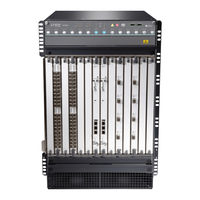
Juniper M-Series Manual (628 pages)
Network and Security Manager
Brand:
Juniper
| Category:
Software
| Size: 7.8 MB
Table of Contents
Table of Contents
7
About this Guide
31
Audience
31
Documentation Conventions
31
Objectives
31
Table 1: Notice Icons
32
Table 2: Text Conventions
32
About this Guide
33
Documentation
33
Table 3: Syntax Conventions
33
Table 4: Network and Security Manager Publications
33
Requesting Technical Support
34
Self-Help Online Tools and Resources
35
Opening a Case with JTAC
35
Getting Started
37
Before You Begin Adding M-Series and MX-Series Devices
37
Chapter 1 Getting Started with NSM
39
Introduction to Network and Security Manager
39
Installing NSM
39
Role-Based Administration
40
Chapter 2 Understanding the JUNOS CLI and NSM
41
NSM and Device Management Overview
41
Understanding the CLI and NSM
42
Comparing the CLI to the NSM UI
43
Understanding the JUNOS CLI and NSM
43
Figure 1: Overview of the User Interface
44
NSM Services Supported for M-Series and MX-Series Devices
46
How NSM Works with the CLI and Distributed Data Collection
47
Device Schemas
48
Figure 2: NSM Network Architecture
48
Documentation
48
Communication between a Device and NSM
49
Chapter 3 Before You Begin Adding M-Series and MX-Series Devices
51
M-Series and MX-Series Devices Supported by NSM
51
Table 5: M Series Multiservice Edge Routers and MX Series Ethernet Services Routers
51
Related M-Series and MX-Series Devices Supported by NSM
51
Considering the Device Status
52
Configuring a Deployed M-Series or MX-Series Device for Importing to NSM
53
The Device
53
Check Network Connectivity
54
Check Connectivity to the NSM Server
54
Configure a Static Route to the NSM Server
54
Establish a Telnet or an Sshv2, and a NETCONF Protocol over SSH Connection to the NSM Server
56
Integrating M-Series and MX-Series Devices
59
Adding M-Series and MX-Series Devices Overview
61
Chapter 4 Adding M-Series and MX-Series Devices Overview
61
About Device Creation
61
Related about Device Creation
61
Supported Add Device Workflows for M-Series and MX-Series Devices
62
Importing Devices Overview
63
Modeling Devices Overview
64
Adding Multiple Devices Using Automatic Discovery (JUNOS Software Devices
64
Only)
65
Adding Device Groups Overview
65
Adding Multiple Devices Using Automatic Discovery (JUNOS Software Devices Only)
65
Documentation
66
Chapter 5 Updating M-Series and MX-Series Devices Overview
67
About Updating M-Series and MX-Series Devices
67
How the Update Process Works
68
Job Manager
69
Updating M-Series and MX-Series Devices Overview
69
Tracking Updated Devices Using Job Manager
70
Reviewing Job Information Displayed in Job Manager
71
Figure 3: Job Information Dialog Box
71
Device States Displayed in Job Manager During Update
72
Documentation
72
Understanding Updating Errors Displayed in the Job Manager
73
Table 6: Device States During Update
73
Figure 4: Failed Update Job Information Dialog Box
74
Configuring M-Series and MX-Series Devices
77
Configuring M-Series and MX-Series Devices Overview
77
Chapter 6 Configuring M-Series and MX-Series Devices Overview
79
About Device Configuration
79
M-Series and MX-Series Device Configuration Settings Supported in NSM
80
Table 7: the JUNOS Configuration Hierarchy and the NSM Configuration
80
Configuring M-Series and MX-Series Devices
81
Configuring Device Features
82
Example: Configuration of Interfaces for MPLS in the CLI and NSM
83
Figure 5: MPLS Configuration in the CLI
83
Figure 6: MPLS Configuration in NSM
84
Configuring Access
85
Chapter 7 Configuring Access
85
Configuring Address-Assignment Pools (NSM Procedure)
85
Table 8: Address Assignment Configuration Details
86
Configuring Access Address Pools (NSM Procedure)
88
Configuring Access Group Profile (NSM Procedure)
89
Table 9: Access Address Pool Configuration Details
89
Table 10: Access Group Profile Configuration Details
89
Configuring the LDAP Options (NSM Procedure)
90
Configuring the LDAP Server (NSM Procedure)
91
Table 11: LDAP Options Configuration Details
91
Configuring Access Profiles for L2TP or PPP Parameters (NSM Procedure)
92
Table 12: LDAP Server Configuration Details
92
Configuring Access Profile (NSM Procedure)
93
Procedure)
93
Configuring RADIUS Parameters for AAA Subscriber Management
93
Table 13: Access Profile Properties Configuration Details
93
Configuring the Accounting Order (NSM Procedure)
94
Table 14: Accounting Parameter Configuration Details
94
Configuring the Authentication Order (NSM Procedure)
95
Configuring the Authorization Order (NSM Procedure)
95
Table 15: Accounting Order Configuration Details
95
Table 16: Authentication Order Configuration Details
95
Configuring the L2TP Client (NSM Procedure)
96
Table 17: Authorization Order Configuration Details
96
Table 18: Client Configuration Details
96
Configuring the Client Filter Name (NSM Procedure)
97
Configuring the LDAP Options (NSM Procedure)
98
Table 19: Client Filter Name Configuration Details
98
Table 20: Ldap Options Configuration Details
98
Configuring the LDAP Server (NSM Procedure)
99
Configuring the Provisioning Order (NSM Procedure)
100
Table 21: Ldap Server Configuration Details
100
Table 22: Provisioning Order Configuration Details
100
Procedure)
101
Table 23: RADIUS Parameter Configuration Details
101
Configuring the RADIUS Parameters (NSM Procedure)
104
Table 24: RADIUS Parameters Configuration Details
104
Configuring Session Limit (NSM Procedure)
105
Configuring the RADIUS for Subscriber Access Management, L2TP, or PPP
105
(NSM Procedure)
105
Table 25: RADIUS Server Configuration Details
105
Configuring the RADIUS for Subscriber Access Management, L2TP, or PPP
106
Procedure)
106
Table 26: Session Limit Configuration Details
106
Configuring the RADIUS for Subscriber Access Management, L2TP, or PPP (NSM Procedure)
106
Configuring the Securid Server (NSM Procedure)
107
Table 27: RADIUS Server Configuration Details
107
Configuring the Access Profile (NSM Procedure)
108
Table 28: Securid Server Configuration Details
108
Table 29: Access Profile Configuration Details
108
Chapter 8 Configuring Accounting Options
109
Configuring Accounting Options (NSM Procedure)
109
Configuring Class Usage Profiles (NSM Procedure)
109
Configuring a Log File (NSM Procedure)
110
Table 30: Class Usage Profile Configuration Details
110
Configuring the Filter Profile (NSM Procedure)
111
Table 31: Log File Configuration Details
111
Configuring the Interface Profile (NSM Procedure)
112
Table 32: Filter Profile Configuration Details
112
Configuring the Policy Decision Statistics Profile (NSM Procedure)
113
Table 33: Interface Profile Configuration Details
113
Configuring the MIB Profile (NSM Procedure)
114
Table 34: Policy Decision Statistics Profile Configuration Details
114
Configuring the Routing Engine Profile (NSM Procedure)
115
Table 35: MIB Profile Configuration Details
115
Table 36: Routing Engine Profile Configuration Details
116
Configuring Applications
117
Chapter 9 Configuring Applications
117
Configuring the Application and Application Set (NSM Procedure)
117
Table 37: Applications Configuration Details
118
Chapter 10 Configuring Bridge Domains
119
Configuring Bridge Domains Properties (NSM Procedure)
119
Configuring a Bridge Domain (NSM Procedure)
119
Configuring Layer 2 Learning and Forwarding Properties for a Bridge Domain (NSM Procedure)
120
Table 38: Bridge Domain Configuration Details
120
Table 39: Bridge Options Configuration Details
121
Configuring Forwarding Options (NSM Procedure)
122
Table 40: Forwarding Options Configuration Details
122
Configuring Logical Interfaces (NSM Procedure)
123
Configuring Multicast Snooping Options (NSM Procedure)
124
Table 41: Logical Interface Configuration Details
124
Table 42: Multicast Snooping Options Configuration Details
125
Configuring IGMP Snooping (NSM Procedure)
127
Table 43: Igmp Snooping Configuration Details
128
Configuring VLAN ID (NSM Procedure)
132
Table 44: VLAN ID Configuration Details
133
Configuring Chassis
135
Chapter 11 Configuring Chassis
135
Configuring Aggregated Devices (NSM Procedure)
135
Configuring Chassis Alarms (NSM Procedure)
136
Table 45: Aggregated Devices Configuration Details
136
Configuring Container Interfaces (NSM Procedure)
137
Table 46: Chassis Alarms Configuration Details
137
Table 47: Container Interfaces Configuration Details
137
Configuring Chassis FPC (NSM Procedure)
138
Table 48: FPC Configuration Details
138
Configuring a T640 Router on a Routing Matrix (NSM Procedure)
143
Table 49: Lcc Configuration Details
143
Configuring Routing Engine Redundancy (NSM Procedure)
148
Table 50: Chassis Redundancy Configuration Details
148
Configuring a Routing Engine to Reboot or Halt on Hard Disk Errors (NSM Procedure)
149
Table 51: Chassis Routing Engine Configuration Details
149
Configuring Authentication
151
Chapter 12 Configuring Authentication
151
Configuring RADIUS Authentication (NSM Procedure)
151
Table 52: RADIUS Authentication Configuration Details
151
Configuring TACACS+ Authentication (NSM Procedure)
152
Table 53: TACACS+ Authentication Configuration Details
152
Configuring Authentication Order (NSM Procedure)
153
Configuring User Access (NSM Procedure)
154
Configuring Login Classes
154
Table 54: Login Class Authentication Configuration Details
154
Configuring User Accounts
155
Configuring Template Accounts (NSM Procedure)
155
Table 55: User Authentication Configuration Details
155
Creating a Remote Template Account
156
Table 56: Remote Template Account Details
156
Creating a Local Template Account
157
Table 57: Local Template Account Details
157
Chapter 13 Configuring Class of Service Features
159
Configuring Cos Classifiers (NSM Procedure)
160
Table 58: Configuring and Applying Behavior Aggregate Classifiers
160
Configuring Cos Code Point Aliases (NSM Procedure)
162
Configuring Cos Drop Profile (NSM Procedure)
163
Table 59: Configuring Code Point Aliases
163
Table 60: Drop Profile Configuration Fields
164
Configuring Cos Forwarding Classes (NSM Procedure)
165
Table 61: Assigning Forwarding Classes to Output Queues
166
Configuring Cos Forwarding Policy (NSM Procedure)
167
Table 62: Forwarding Policy Configuration Details
167
Configuring Cos Fragmentation Maps (NSM Procedure)
168
Configuring Cos Host Outbound Traffic (NSM Procedure)
169
Table 63: Fragmentation Maps Configuration Details
169
Configuring Cos Interfaces (NSM Procedure)
170
Table 64: Host Outbound Traffic Configuration Details
170
Table 65: Interfaces Configuration Fields
171
Configuring Cos Routing Instances (NSM Procedure)
176
Table 66: Routing Instances Configuration Details
176
Configuring Cos Schedulers (NSM Procedure)
177
Table 67: Configuring Schedulers
178
Configuring Cos and Applying Scheduler Maps (NSM Procedure)
179
Table 68: Assigning Forwarding Classes to Output Queues
179
Configuring Cos Restricted Queues (NSM Procedure)
180
Configuring Tracing Operations (NSM Procedure)
181
Table 69: Restricted Queue Configuration Details
181
Table 70: Traceoptions Configuration Details
181
Configuring Cos Traffic Control Profiles (NSM Procedure)
182
Configuring Cos Translation Table (NSM Procedure)
183
Table 71: Traffic Control Profile Configuration Details
183
Table 72: Translation Table Configuration Details
184
Chapter 14 Configuring Event Options
189
Configuring Destinations for File Archiving (NSM Procedure)
189
Table 73: Destination Configuration Details
189
Configuring Event Script (NSM Procedure)
190
Table 74: Event Script Configuration Details
191
Generating Internal Events (NSM Procedure)
192
Configuring Event Policy (NSM Procedure)
192
Table 75: Generate Event Details
192
Table 76: Configure Event Policy Details
193
Configuring Event Policy Tracing Operations (NSM Procedure)
195
Table 77: Event Options Traceoptions Configuration Details
196
Configuring Firewall
197
Chapter 15 Configuring Firewall
197
Configuring the Firewall Filter for any Family Type (NSM Procedure)
197
Table 78: Firewall Filter Configuration Details
198
Configuring the Firewall Filter for Bridge Family Type (NSM Procedure)
199
Table 79: Bridge Filter Configuration Details
199
Configuring the Firewall Filter for CCC Family Type (NSM Procedure)
201
Table 80: CCC Filter Configuration Details
201
Configuring Filters for Inet Family Type (NSM Procedure)
203
Configuring Firewall Filter for Inet Family Type (NSM Procedure)
203
Table 81: Firewall Filter Configuration Details
203
Configuring Prefix-Specific Actions (NSM Procedure)
205
Configuring Service Filters (NSM Procedure)
206
Table 82: Prefix Actions Details
206
Table 83: Service Filter Configuration Details
206
Configuring Simple Filters (NSM Procedure)
207
Configuring Filters for Inet6 Family Type (NSM Procedure)
208
Table 84: Simple Filter Details
208
Configuring Firewall Filter for Inet6 Family Type (NSM Procedure)
209
Table 85: Inet6 Firewall Filter Configuration Details
209
Configuring Service Filters for Inet6 (NSM Procedure)
211
Table 86: Inet6 Service Filter Configuration Details
211
Configuring the Firewall Filter for MPLS Family Type (NSM Procedure)
212
Table 87: MPLS Firewall Filter Configuration Details
213
Configuring the Firewall Filter for VPLS Family Type (NSM Procedure)
215
Table 88: VPLS Firewall Filter Configuration Details
216
Configuring a Policer for a Firewall Filter
218
Table 89: Configuring a Policer for a Firewall Filter
218
Chapter 16 Configuring Forwarding Options
221
Configuring Accounting Options (NSM Procedure)
221
Table 90: Accounting Options Configuration Details
221
Configuring the Extended DHCP Agent (NSM Procedure)
223
Configuring Authentication Support for the DHCP Relay Agent
223
Procedure)
223
Configuring Group (NSM Procedure)
224
Table 91: Authentication Configuration Details
224
Overriding the Default Configuration Settings for the Extended DHCP Relay
225
Agent (NSM Procedure)
225
Table 92: Group Configuration Details
225
Table 93: Overrides Configuration Details
226
Configuring Relay Option 60 Information for Forwarding Client Traffic to
227
Specific DHCP Servers (NSM Procedure)
227
Table 94: Relay Option 60 Configuration Details
227
Configuring Relay Option 82 for a DHCP Server (NSM Procedure)
228
Specifying the Name of a Group of DHCP Server Addresses for Use by the Extended DHCP Relay Agent (NSM Procedure)
229
Table 95: Relay Option 82 Configuration Details
229
Configuring Operations for Extended DHCP Relay Agent Processes
230
Procedure)
230
Table 96: Sever Group Configuration Details
230
Table 97: DHCP Relay Traceoptions Configuration Details
230
Specifying Address Family for Filters (NSM Procedure)
231
Table 98: Address Family Details
231
Configuring Load Balancing Using Hash Key (NSM Procedure)
232
Configuring Helpers (NSM Procedure)
233
Table 99: Load Balance Configuration Details
233
Configuring a Router or Interface to Act as a Bootstrap Protocol Relay
234
Agent
234
Table 100: BOOTP Configuration Details
234
Enabling DNS Request Packet Forwarding
237
Table 101: DNS and TFTP Configuration Details
238
Configuring a Port for a DHCP or BOOTP Relay Agent
239
Configuring Tracing Operations for BOOTP, DNS, and TFTP Packet
240
Forwarding
240
Table 102: Port Configuration Details
240
Configuring Per-Flow and Per-Prefix Load Balancing (NSM Procedure)
241
Table 103: Traceoptions Configuration Details
241
Configuring Port Mirroring (NSM Procedure)
242
Table 104: Load Balancing Configuration Details
242
Table 105: Port Mirroring Configuration Details
243
Configuring Interfaces
245
Chapter 17 Configuring Interfaces
245
Configuring Interfaces on the Routing Platform (NSM Procedure)
245
Configuring Interface Properties (NSM Procedure)
245
Configuring Tracing Operations of an Individual Router Interface
245
Table 106: Interface Properties Configuration Details
246
Damping Interface Transitions (NSM Procedure)
247
Table 107: Hold Time Configuration Details
247
Configuring Receive Bucket Properties on Interfaces (NSM Procedure)
248
Procedure)
248
Table 108: Receive Bucket Configuration Details
248
Configuring Transmit Leaky Bucket Properties (NSM Procedure)
249
Table 109: Trace Options Configuration Details
249
Configuring Logical Interface Properties (NSM Procedure)
250
Configuring Epd Threshold for the Logical Interface
250
Configuring Logical Unit Properties (NSM Procedure)
250
Table 110: Transmit Bucket Configuration Details
250
Configuring an IP Demux Underlying Interface (NSM Procedure)
251
Table 111: Logical Unit Configuration Details
251
Configuring the Logical Demux Source Family Type on the IP Demux Underlying Interface (NSM Procedure)
252
Procedure)
252
Table 112: IP Demux Configuration Details
252
Table 113: IP Demux Source Configuration Details
252
Configuring Protocol Family Information for the Logical Interface
253
Configuring Protocol Family (CCC) Information for the Logical Interface (NSM Procedure)
253
Procedure)
253
Table 114: Epd Threshold Configuration Details
253
Table 115: CCC Family Configuration Details
254
(NSM Procedure)
255
Configuring Protocol Family (Inet) Information for the Logical Interface
255
Table 116: Inet Family Configuration Details
256
(NSM Procedure)
261
Configuring Protocol Family (Inet6) Information for the Logical Interface (NSM
261
Table 117: Inet6 Family Configuration Details
262
(NSM Procedure)
267
Configuring Protocol Family (ISO) Information for the Logical Interface (NSM
267
(NSM Procedure)
268
Configuring Protocol Family (MPLS) Information for the Logical Interface (NSM
268
Table 118: Iso Family Configuration Details
268
Table 119: MPLS Family Configuration Details
269
(NSM Procedure)
270
Configuring Protocol Family (TCC) Information for the Logical Interface (NSM
270
Configuring the Traffic Shaping Profile (NSM Procedure)
270
Table 120: TCC Family Configuration Details
270
Table 121: Traffic Shaping Configuration Details
271
Configuring Interface Set on the Routing Platform (NSM Procedure)
272
Table 122: Interface Set Configuration Details
272
Configuring Trace Options on the Routing Platform (NSM Procedure)
273
Table 123: Traceoption Configuration Details
273
Chapter 18 Configuring Multicast Snooping Options
275
Configuring Multicast Snooping Options (NSM Procedure)
275
Table 124: Multicast Snooping Options Configuration Details
276
Chapter 19 Configuring Policy Options
279
Configuring an as Path in a BGP Routing Policy (NSM Procedure)
279
Configuring an as Path Group in a BGP Routing Policy (NSM Procedure)
280
Table 125: as Path Configuration Details
280
Configuring a Community for Use in BGP Routing Policy Conditions
281
Procedure)
281
Table 126: as Path Group Configuration Details
281
Configuring a BGP Export Policy Condition (NSM Procedure)
282
Table 127: Community Configuration Details
282
Configuring Flap Damping to Reduce the Number of BGP Update Messages(NSM Procedure)
283
Table 128: Condition Configuration Details
283
Table 129: Damping Configuration Details
284
Configuring a Routing Policy Statement (NSM Procedure)
285
Table 130: Configuring Policy Statement Fields
285
Configuring Prefix List (NSM Procedure)
286
Table 131: Configuring Prefix List Fields
287
Configuring Protocols
289
Juniper M-Series Configuration Manual (35 pages)
Routers with MS-DPC/MS-PIC
Brand:
Juniper
| Category:
Network Router
| Size: 0.47 MB
Table of Contents
Table of Contents
2
1 Introduction
4
2 Scope
4
3 Design Considerations
4
4 Terminology
4
5 Implementation: Juniper 6Rd Solution
5
6Rd Feature Summary
5
Figure 1: Packet Flow on the Br
5
7 Configuration Examples
6
Topology
6
Figure 2: Topology Illustrating Multiple 6Rd Domains
6
Basic 6Rd Configuration
7
6Rd Routes
8
Advertising 6Rd Routes
8
Interface Style Service Set
8
Next-Hop Style Service Set
10
Pinging 6Rd Softwire Concentrator
12
6Rd Domain to Internet
12
Interfaces Configuration
12
Service Set Configuration
13
Softwire Concentrator Configuration
13
Stateful Firewall Configuration
13
Interfaces Configuration
14
Service Set Configuration
15
Softwire Concentrator Configuration
15
Stateful Firewall Configuration
16
6To4 Using 6Rd
16
Interfaces Configuration
16
Service Set Configuration
17
Softwire Concentrator Configuration
17
Stateful Firewall Configuration
17
6Rd Anycast (Redundancy)
18
Interfaces Configuration
18
Service Set Configuration
19
Softwire Concentrator Configuration
19
Stateful Firewall Configuration
21
6Rd + DS-Lite in same Service Set
21
Interfaces Configuration
21
Service Set Configuration
22
Softwire Concentrator Configuration
23
Stateful Firewall Configuration
24
NAT Configuration
24
8 Configuration Tips
25
Configuration Tips
25
9 Operations and Management
25
6Rd CLI
25
Flows and Conversations
25
Softwire
26
Debug CLI
27
12 Appendix
27
Figure 3: Topology Used to Illustrate CLI Commands for 6Rd Deployment and Operations
32
10 ALG Support
27
11 Summary
27
13 Bibliography
35
About Juniper Networks
35
Advertisement
Juniper M-Series Datasheet (8 pages)
M-Series Routing Platforms
Brand:
Juniper
| Category:
Network Hardware
| Size: 0.15 MB
Advertisement
Related Products
Juniper M40
Juniper M40e
Juniper M5
Juniper M7i
Juniper M320
Juniper MX240
Juniper MX2020
Juniper MX5
Juniper MX10
Juniper MX80
Juniper Categories
Network Router
Switch
Gateway
Software
Network Hardware
More Juniper Manuals
Login
Sign In
OR
Sign in with Facebook
Sign in with Google
Upload manual
Upload from disk
Upload from URL