Sign In
Upload
Manuals
Brands
Juniper Manuals
Network Router
M320
Juniper M320 Manuals
Manuals and User Guides for Juniper M320. We have
5
Juniper M320 manuals available for free PDF download: Hardware Manual, Quick Start Manual, Datasheet
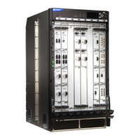
Juniper M320 Hardware Manual (392 pages)
Multiservice Edge Router
Brand:
Juniper
| Category:
Network Router
| Size: 9.51 MB
Table of Contents
Table of Contents
3
List of Tables
19
About the Documentation
23
Documentation and Release Notes
23
Documentation Conventions
23
Supported Platforms
23
Table 1: Notice Icons
24
Table 2: Text and Syntax Conventions
24
Documentation Feedback
25
About the Documentation
25
Opening a Case with JTAC
26
Requesting Technical Support
26
Self-Help Online Tools and Resources
26
Overview
29
Chassis Components and Descriptions
29
Cooling System Components and Descriptions
29
Host Subsystem Components and Descriptions
29
Line Card Components and Descriptions
29
Power System Components and Descriptions
29
Switch Fabric Components and Descriptions
29
Chapter 1 System Overview
31
M320 Router Description
31
M320 Component Redundancy
32
Chapter 2 M320 Router Release Notes
33
M320 Router Release Notes
33
Errata with the M320 Router Documentation
33
Outstanding Issues with the M320 Router
33
Chassis Components and Descriptions
35
Chapter 3 Chassis Components and Descriptions
35
M320 Chassis Description
35
Figure 1: Front View of a Fully Configured Router Chassis
36
Figure 2: Rear View of a Fully Configured AC-Powered Router Chassis
37
M320 Midplane Description
38
Figure 3: Rear View of a Fully Configured DC-Powered Router Chassis
38
Figure 4: Midplane
39
Chassis Components and Descriptions
39
M320 Fuses
40
M320 Cable Management System Description
40
Figure 5: Cable Management System
40
M320 Connector Interface Panel (CIP) Description
41
CIP Components
41
Figure 6: CIP
42
Routing Engine Ports
42
Alarm Relay Contacts
43
M320 Craft Interface Description
43
Figure 7: Front Panel of the Craft Interface
43
M320 Craft Interface Alarm Leds and ACO/LT Button
44
M320 Craft Interface LED Display and Navigation Buttons
44
Table 3: Alarm Leds and Alarm Cutoff/Lamp Test Button
44
M320 Connector Interface Panel (CIP) Description
44
M320 Craft Interface Description
44
Figure 8: LED Display in Idle Mode
45
Figure 9: LED Display in Alarm Mode
45
M320 Craft Interface Host Subsystem Leds
46
M320 Craft Interface FPC Leds and Online/Offline Buttons
46
Table 4: M320 Host Subsystem Leds
46
Table 5: FPC Leds
46
M320 Craft Interface Power Supply Leds
47
M320 Craft Interface SIB Leds
47
Table 6: Power Supply Leds on the Craft Interface
47
Table 7: SIB Leds on the Craft Interface
47
Chapter 4 Cooling System Components and Descriptions
49
M320 Cooling System Description
49
Figure 10: Airflow through the Chassis
49
Components
50
Chapter 5 Host Subsystem Components and Descriptions
51
M320 Host Subsystem Description
51
M320 Routing Engine Description
52
M320 Routing Engine 600 Description
53
Figure 11: Routing Engine 1600
54
M320 Routing Engine 1600 Description
54
M320 Routing Engine 2000 Description
55
Figure 12: Routing Engine 2000
56
M320 RE-A-1800 Routing Engine Description
56
Routing Engine Components
56
Figure 13: RE-A-1800 Routing Engine
57
Figure 14: RE-A-1800X2 Routing Engine
57
Figure 15: USB Memory Device in an Routing Engine
58
Routing Engine Boot Sequence
58
RE-A-1800 Routing Engine Leds
59
Routing Engine Specifications
59
Table 8: Routing Engine Leds
59
Table 9: Routing Engine Specifications
59
Table 10: End-Of-Life Routing Engine Specifications
61
M7I Routing Engines
62
Supported Routing Engines by Router
62
M10I Routing Engines
63
M40E Routing Engines
63
Table 11: M7I Routing Engines
63
Table 12: M10I Routing Engines
63
Table 13: M40E Routing Engines
63
M120 Routing Engines
64
M320 Routing Engines
64
Table 14: M120 Routing Engines
64
Table 15: M320 Routing Engines
64
MX104 Routing Engines
65
MX240 Routing Engines
65
Table 16: MX104 Routing Engines
65
Table 17: MX240 Routing Engines
65
MX480 Routing Engines
66
Table 18: MX480 Routing Engines
66
MX2010 Routing Engines
67
MX960 Routing Engines
67
Table 19: MX960 Routing Engines
67
Table 20: MX2010 Routing Engines
67
MX2020 Routing Engines
68
PTX3000 Routing Engines
68
PTX5000 Routing Engines
68
Table 21: MX2020 Routing Engines
68
Table 22: PTX3000 Routing Engines
68
Table 23: PTX5000 Routing Engines
68
T320 Routing Engines
69
T640 Routing Engines
69
Table 24: T320 Routing Engines
69
Table 25: T640 Routing Engines
69
T1600 Routing Engines
70
Table 26: T1600 Routing Engines
70
T4000 Routing Engines
71
Table 27: T4000 Routing Engines
71
Table 28: TX Matrix Routing Engines
72
Table 29: TX Matrix Plus Routing Engines
72
TX Matrix Plus (with 3D Sibs) Routing Engines
72
TX Matrix Plus Routing Engines
72
TX Matrix Routing Engines
72
Figure 16: CB
73
M320 Control Board (CB) Description
73
Table 30: Routing Engines on TX Matrix Plus with 3D Sibs
73
M320 Control Board (CB) Leds
74
Table 31: M320 CB Leds
74
Chapter 6 Line Card Components and Descriptions
77
M320 Flexible PIC Concentrator (FPC) Description
77
Figure 17: FPC Installed in Router Chassis
78
Figure 18: FPC1, FPC2, and FPC3 for the M320 Router
79
Line Card Components and Descriptions
79
Figure 19: Enhanced II FPC1, FPC2, and FPC3 for the M320 Router
80
Figure 20: Enhanced III FPC1, FPC2, and FPC3 for the M320 Router
80
M320 FPC Terminology
81
M320 Fpcs Supported
81
Figure 21: FPC Edges
81
M320 PIC Description
82
Table 32: Fpcs Supported by the M320 Router
82
M320 Pics Supported
83
Table 33: ATM IQ Pics Supported by the M320 Router
83
Table 34: ATM2 IQ Pics Supported by the M320 Router
84
Table 35: Channelized Pics Supported by the M320 Router
84
Table 36: Channelized IQ Pics Supported by the M320 Router
85
Table 37: Channelized IQE Pics Supported by the M320 Router
85
Table 38: Circuit Emulation Pics Supported by the M320 Router
86
Table 39: DS3, E1, E3, and T1 Pics Supported by the M320 Router
86
Table 40: EIA-530 PIC Supported by the M320 Router
87
Table 41: Fast Ethernet Pics Supported by the M320 Router
87
Table 42: Gigabit Ethernet Pics Supported by the M320 Router
88
Table 43: 10-Gigabit Ethernet Pics Supported by the M320 Router
90
Table 44: Service Pics Supported by the M320 Router
90
Table 45: SONET/SDH Pics Supported by the M320 Router
91
M320 End-Of-Life Pics Supported
92
Table 46: End-Of-Life Pics Supported in the M320 Router
92
M320 PIC Combination Limitations
94
M320 PIC/FPC Compatibility
94
PIC/FPC Compatibility (Type 1 Fpcs and Type 1 Pics)
95
Table 47: M320 PIC/FPC Compatibility Type 1
96
PIC/FPC Compatibility (Type 2 Fpcs and Type 2 Pics)
98
PIC/FPC Compatibility (Type 3 Fpcs and Type 3 Pics)
99
Table 48: M320 PIC/FPC Compatibility Type 2
99
Table 49: M320 PIC/FPC Compatibility Type 3
100
Chapter 7 Power System Components and Descriptions
101
M320 Power System Description
101
M320 AC Power Supplies Description
101
Figure 22: AC Power Supply
102
Components Powered by each Power Supply Slot
103
Isolated DC Power Supply
103
Nonisolated DC Power Supply
103
Table 50: Components Powered by each DC Power Supply Slot
103
DC Power Supply Load Sharing and Fault Tolerance
104
M320 DC Power Supplies Description
102
M320 Power Supply Leds
104
Table 51: Power Supply LED
104
Chapter 8 Switch Fabric Components and Descriptions
107
M320 Performance for Different SIB Configurations
108
Table 52: Performance Per SIB/FPC Configuration
108
M320 SIB Leds
109
Table 53: SIB Leds
109
Site Planning, Preparation, and Specifications
111
AC Power Specifications
111
DC Power Specifications
111
Advertisement
Juniper M320 Hardware Manual (320 pages)
Multiservice Edge Router
Brand:
Juniper
| Category:
Network Router
| Size: 9.47 MB
Table of Contents
Hardware Guide
1
Table of Contents
7
About the Documentation
21
Junos os Documentation and Release Notes
21
Objectives
21
Audience
22
Documentation Conventions
22
Table 1: Notice Icons
22
Table 2: Text and Syntax Conventions
22
About the Documentation
23
Documentation Feedback
23
Requesting Technical Support
24
Self-Help Online Tools and Resources
24
Opening a Case with JTAC
25
M320 Hardware Components
27
M320 Multiservice Edge Router Overview
27
Preparing the Site for M320 Router Installation
27
Chapter 1 M320 Router Overview
29
M320 Router Description
29
M320 Router Overview
29
Chapter 2 M320 Hardware Components
31
M320 Component Redundancy
31
M320 Chassis Description
32
Figure 1: Front View of a Fully Configured Router Chassis
33
M320 Hardware Components
33
Figure 2: Rear View of a Fully Configured AC-Powered Router Chassis
34
Figure 3: Rear View of a Fully Configured DC-Powered Router Chassis
35
M320 Midplane Description
35
Figure 4: Midplane
36
M320 Flexible PIC Concentrator (FPC) Description
37
Figure 5: FPC Installed in Router Chassis
38
Figure 6: FPC1, FPC2, and FPC3 for the M320 Router
39
Figure 7: Enhanced II FPC1, FPC2, and FPC3 for the M320 Router
39
Figure 8: Enhanced III FPC1, FPC2, and FPC3 for the M320 Router
40
M320 Fpcs Supported
40
Table 3: Fpcs Supported by the M320 Router
40
M320 PIC Description
41
Figure 9: SIB-M
42
M320 SIB Description
42
M320 Switch Interface Board (SIB) Overview
42
Table 4: SIB Leds
42
M320 Performance for Different SIB Configurations
43
Table 5: Performance Per SIB/FPC Configuration
43
M320 Host Subsystem Description
44
M320 Host Subsystem Overview
44
M320 Routing Engine Description
45
M320 Routing Engine 600
46
Figure 10: Routing Engine 1600
47
M320 Routing Engine 1600
47
Figure 11: Routing Engine 2000
48
M320 Routing Engine 2000
48
M320 Control Board (CB) Description
49
Figure 12: CB
50
M320 Connector Interface Panel (CIP) Description
51
M320 Connector Interface Panel (CIP) Overview
51
M320 Control Board (CB) Leds
51
Table 6: M320 CB Leds
51
Figure 13: CIP
52
M320 Routing Engine Ports
52
M320 Craft Interface Overview
53
T640 Alarm Relay Contacts
53
Figure 14: Front Panel of the Craft Interface
54
M320 Craft Interface Alarm Leds and ACO/LT Button
54
M320 Craft Interface Description
54
Figure 15: LED Display in Idle Mode
55
M320 Craft Interface LED Display and Navigation Buttons
55
Table 7: Alarm Leds and Alarm Cutoff/Lamp Test Button
55
Figure 16: LED Display in Alarm Mode
56
M320 Craft Interface Host Subsystem Leds
56
Table 8: M320 Host Subsystem Leds
56
M320 Craft Interface Power Supply Leds
57
M320 Craft Interface SIB Leds
57
Table 10: Power Supply Leds on the Craft Interface
57
Table 9: SIB Leds on the Craft Interface
57
M320 Craft Interface FPC Leds and Online/Offline Buttons
58
Table 11: FPC Leds
58
M320 AC Power Supply
59
M320 Power System Description
59
M320 Power System Overview
59
Figure 17: AC Power Supply
60
M320 DC Power Supply
60
Figure 18: DC Power Supply
61
M320 Power Supply Leds
61
Table 12: Power Supply LED
61
M320 Fuse Specifications
62
M320 Fuses
62
Table 13: Fuse Specifications
62
M320 Cooling System Description
63
Figure 19: Airflow through the Chassis
64
M320 Cable Management System Description
64
Figure 20: Cable Management System
65
Chapter 3 Preparing the Site for M320 Router Installation
67
M320 Site Preparation Checklist Requirements
67
Rack
67
Table 14: Site Preparation Checklist
67
Rack Requirements for the M320 Router
68
Figure 21: Typical Open-Frame Rack
69
Preparing the Site for M320 Router Installation
69
Figure 22: Chassis Dimensions and Clearance Requirements
70
M320 Clearance Requirements
70
Figure 23: Typical Open-Frame Rack
71
M320 Cabinet Requirements
71
M320 Cabinet Size and Clearance Requirements
72
Table 15: Cabinet Clearance Requirements
72
M320 Cabinet Airflow Requirements
73
Figure 24: Airflow Baffle Template
74
Chapter 4 Unpacking the M320 Router
75
M320 Router Installation Summary
75
Tools and Parts Required to Unpack the M320 Router
75
Unpacking the M320 Router
76
Verifying the M320 Router Parts Received
77
Figure 25: Contents of the T1600 Shipping Crate
77
Table 16: M320 Router Parts List for a Fully Configured Router
77
Unpacking the M320 Router
77
Table 17: M320 Router Accessory Box Parts List
78
Chapter 5 Installing the M320 Router Mounting Hardware
81
Verifying the M320 Rack-Mounting Hardware Received
81
M320 Mounting Hole Locations for Four-Post Racks or Cabinets
82
Installing the M320 Mounting Hardware for a Four-Post Rack or Cabinet
82
Table 18: Four-Post or Cabinet Rack Mounting Hole Locations
82
Cabinets
83
Figure 26: Installing the Mounting Hardware for a Four-Post Rack or Cabinet
83
Installing Cage Nuts (if Needed) for M320 Four-Post Racks or Cabinets
83
Installing the Large Mounting Shelf for M320 Four-Post Racks or
83
Cabinets
84
Removing the Adjustable Center-Mounting Brackets for M320 Four-Post Racks or Cabinets
84
Figure 27: Center-Mounting Bracket Removal
85
M320 Mounting Hole Locations for Open-Frame Racks
85
Installing the M320 Router Mounting Hardware
83
Installing the M320 Router Mounting Hardware
85
Table 19: Open-Frame Rack Mounting Hole Locations
85
Installing the M320 Mounting Hardware for Open-Frame Racks
86
Figure 28: Installing the Mounting Hardware for a Center-Mount Open-Frame
87
Installing Cage Nuts (if Needed) for M320 Open Frame Racks
87
Moving the Adjustable Center-Mounting Brackets for M320 Open-Frame
87
Racks
87
Installing the Large Mounting Shelf for the M320 Open-Frame Racks
88
Installing the Small Mounting Shelf for the M320 Open-Frame Racks
88
Chapter 6 Installing the M320 Router Using a Mechanical Lift
89
Tools Required to Install the M320 Router Using a Mechanical Lift
89
Attaching the Installation Handle to the M320 Router
90
Removing the M320 Installation Handle and Reinstalling the Power
90
Figure 29: Removing an M320 Power Supply before Installing the Installation
91
Figure 30: Attaching the M320 Installation Handle
91
Mounting the M320 Chassis Using a Mechanical Lift
91
Figure 31: Installing the M320 Router in the Rack
93
Supplies
93
Installing the M320 Cable Guards
94
Figure 32: Reinstalling an M320 Power Supply
94
Figure 33: Installing the M320 Cable Guards
95
Chapter 7 Installing the M320 Router Without a Mechanical Lift
97
Lift
97
Removing M320 Components from the Chassis
97
Figure 34: Removing a Power Supply before Installing the Router
98
Removing the M320 Power Supplies
98
Figure 35: Removing a SIB
99
Removing the M320 Sibs
99
Figure 36: Removing a CB
100
Removing the M320 Cbs
100
Removing the M320 Rear Fan Tray
100
Figure 37: Removing the Rear Fan Tray
101
Figure 38: Removing the Cable Management System
102
Removing the M320 Cable Management System
102
Removing the M320 Front Fan Trays
102
Figure 39: Removing a Front Fan Tray
103
Removing the M320 Fpcs
103
Figure 40: Removing an FPC
104
Figure 41: Attaching the Installation Handle
105
Installing the M320 Chassis in the Rack Manually
105
Figure 42: Installing the Router in the Rack
107
Reinstalling M320 Components in the Chassis
107
Figure 43: Reinstalling the Rear Fan Tray
108
Reinstalling an M320 Rear Fan Tray
108
Figure 44: Reinstalling a CB
109
Reinstalling the M320 Cbs
109
Reinstalling the M320 Sibs
109
Figure 45: Reinstalling a SIB
110
Reinstalling the M320 Power Supplies
110
Figure 46: Reinstalling a Power Supply
111
Reinstalling the M320 Fpcs
111
Figure 47: Reinstalling an FPC
112
Reinstalling M320 Front Fan Trays
112
Figure 48: Reinstalling a Front Fan Tray
113
Reinstalling the M320 Cable Management System
113
Installing the M320 Router Without a Mechanical Lift
99
Chapter 8 Connecting the M320 Router
115
Tools and Parts Required for M320 Router Connections
115
Devices
115
Device
116
Figure 49: Routing Engine Management Ports and Alarm Relay Contacts
116
Management
116
Connecting the M320 Router to Management and Alarm Devices
117
Figure 50: Routing Engine Ethernet Cable Connector
117
Connecting PIC Cables to the M320 Router
118
Connecting the M320 Router to an External Alarm-Reporting Device
118
Figure 51: Console and Auxiliary Serial Port Connector
118
Figure 52: Attaching Cable to a PIC
119
Figure 53: Installing the Cable Cover
120
Chapter 9 Providing Power to the M320 Router
121
Grounding the M320 Router
121
Connecting Power to an AC-Powered M320 Router
122
Connecting Power to a DC-Powered M320 Router
123
Figure 54: Connecting AC Power to the M320 Router
123
Figure 55: Connecting DC Power to the M320 Router
125
Powering on the M320 Router
125
Powering off the M320 Router
127
Providing Power to the M320 Router
123
Chapter 10 Performing the Initial M320 Router Configuration
129
Initially Configuring the M320 Router
129
M320 Hardware Maintenance, Troubleshooting, and Replacement Procedures
133
Replacing the M320 Router Hardware Components
133
Troubleshooting M320 Router Hardware Components
133
Chapter 11 Maintaining M320 Router Hardware Components
135
Tools and Parts Required to Maintain the M320 Hardware Components
135
Routine Maintenance Procedures for the M320 Router
135
Maintaining the M320 Air Filters
136
Maintaining the M320 Fan Trays
137
Maintaining the M320 Host Subsystem
137
Maintaining M320 Fpcs
139
M320 FPC Terminology
140
Holding and Storing M320 Fpcs
141
Figure 56: FPC Edges
141
Holding M320 Fpcs
141
Figure 57: Do Not Grasp the Connector Edge
142
Figure 58: Do Not Carry an FPC with Only One Hand
143
Figure 59: Do Not Rest the FPC on an Edge
143
Figure 60: Holding an FPC Vertically
144
Storing M320 Fpcs
144
Maintaining M320 Pics and PIC Cables
145
Figure 61: Do Not Stack Fpcs
145
Maintaining the M320 Sibs
147
Maintaining the M320 Power Supplies
148
Chapter 12 Troubleshooting M320 Router Hardware Components
151
M320 Troubleshooting Resources Overview
151
M320 LED Overview
152
Component Leds
152
Craft Interface Leds
152
M320 Chassis and Interface Alarm Messages
153
Table 20: M320 Chassis Alarm Messages
153
Troubleshooting M320 Router Hardware Components
153
Table 21: SONET/SDH Interface Alarm Messages
154
Troubleshooting the M320 Cooling System
155
Figure 62: Airflow through the Chassis
156
Troubleshooting the M320 Fpcs
157
Troubleshooting the M320 Pics
158
Troubleshooting the M320 Power System
158
Troubleshooting the M320 Fuses
159
Figure 63: Fuses in the Midplane
160
Chapter 13 Replacing the M320 Router Hardware Components
163
M320 FRU Description
163
Tools and Parts Required to Replace the M320 Hardware Components
164
Table 22: Field-Replaceable Units
164
Table 23: Tools and Parts Required
164
Replacing the M320 CIP
166
Removing an M320 CIP
166
Figure 64: Removing the CIP
167
Installing an M320 CIP
167
Figure 65: Installing a CIP
168
Replacing the M320 Connections to Routing Engine Interface Ports
168
Figure 66: Routing Engine Interface Ports and Alarm Relay Contacts
169
Replacing the M320 Management Ethernet Cables
169
Figure 67: Ethernet Cable Connectors
171
Removing an M320 Console or Auxiliary Cable
171
Figure 68: Routing Engine Console or Auxiliary Cable
172
Installing an M320 Console or Auxiliary Cable
172
Figure 69: Routing Engine Console or Auxiliary Cable
173
Replacing the M320 Alarm Relay Wires
173
Replacing an M320 Air Filter
174
Removing a Front M320 Air Filter
174
Figure 70: Removing the Front Air Filter
175
Figure 71: Replacing the Front Filter Element
175
Figure 72: Installing the Front Air Filter
176
Installing a Front M320 Air Filter
176
Removing a Rear M320 Air Filter
176
Figure 73: Removing the Rear Air Filter
177
Figure 74: Removing the Rear Air Filter Element
178
Installing a Rear M320 Air Filter
178
Replacing an M320 Fan Tray
179
Figure 75: Installing the Rear Air Filter
179
Removing an M320 Front Fan Tray
179
Figure 76: Removing a Front Fan Tray
181
Figure 77: Installing a Front Fan Tray
181
Installing an M320 Front Fan Tray
181
Removing an M320 Rear Fan Tray
182
Figure 78: Removing the Rear Fan Tray
183
Installing an M320 Rear Fan Tray
183
Replacing an M320 Craft Interface
184
Figure 79: Installing a Rear Fan Tray
184
Removing an M320 Craft Interface
184
Figure 80: Removing the Craft Interface
185
Installing an M320 Craft Interface
185
Replacing M320 Host Subsystem Components
186
Figure 81: Installing the Craft Interface
186
Table 24: Effect of Taking the Host Subsystem Offline
186
Taking the M320 Host Subsystem Offline
186
Replacing an M320 CB, Routing Engine, or Routing Engine Component
189
Replacing an M320 CB
189
Removing an M320 CB
189
Figure 82: Removing a CB
190
Figure 83: Installing a CB
191
Installing an M320 CB
191
Replacing an M320 Routing Engine
192
Removing an M320 Routing Engine
192
Figure 84: Removing a Routing Engine
193
Installing an M320 Routing Engine
193
Replacing a DIMM Module in an M320 Routing Engine
194
Figure 85: Installing a Routing Engine
194
Removing an M320 DIMM Module
194
Figure 86: Installing the DIMM Module
195
Installing an M320 DIMM Module
195
Inserting or Removing a PC Card from an M320 Routing Engine
196
Inserting a PC Card into an M320 Routing Engine
196
Figure 87: Installing a PC Card
197
Removing an M320 PC Card
197
Replacing an M320 SIB
198
Figure 88: Removing a PC Card
198
Handle
198
Removing an M320 SIB
198
Figure 89: Removing a SIB
199
Installing an M320 SIB
199
Figure 90: Installing a SIB
200
Removing an M320 FPC
201
Replacing an M320 FPC
201
Figure 91: Removing an FPC
203
Installing an M320 FPC
203
Figure 92: Installing an FPC
205
Figure 93: Connecting Fiber-Optic Cable to a PIC
206
Removing an M320 PIC
206
Replacing an M320 PIC
206
Figure 94: Removing a PIC
208
Installing an M320 PIC
208
Figure 95: Installing a PIC
210
Replacing M320 PIC Cables
210
Installing an M320 PIC Cable
211
Removing an M320 PIC Cable
211
Figure 96: Connecting Fiber-Optic Cable to a PIC
213
Replacing an M320 SFP
213
Figure 97: Small Form-Factor Pluggable (SFP)
214
Removing an M320 SFP
214
Installing an M320 SFP
215
Removing an M320 XENPAK Module
216
Replacing an M320 XENPAK Module
216
Figure 98: Removing a XENPAK Module
217
Installing an M320 XENPAK Module
217
Figure 99: Installing a XENPAK Module
219
Removing an M320 AC Power Supply
219
Replacing an M320 AC Power Supply
219
Replacing M320 Power System Components
219
Figure 100: Removing an AC Power Supply
221
Figure 101: Rear of the Power Supply Showing Midplane Connector
221
Installing an M320 AC Power Supply
221
Figure 102: Installing an AC Power Supply
222
Replacing an M320 DC Power Supply
222
Figure 103: Disconnecting Power Cables from the DC Power Supply
223
Removing an M320 DC Power Supply
223
Figure 104: Removing a DC Power Supply
224
Installing an M320 DC Power Supply
225
Figure 105: Installing a DC Power Supply
226
Figure 106: Connecting Power Cables to the DC Power Supply
226
Replacing an M320 AC Power Supply Cord
227
Replacing an M320 DC Power Supply Cable
228
Figure 107: Disconnecting or Connecting a Power Cable from a DC Power
229
Supply
229
Replacing an M320 Fuse
230
Figure 108: Fuses in the Midplane
232
Replacing M320 Packet Forwarding Engine Components
200
Juniper M320 Hardware Manual (320 pages)
Multiservice Edge Router
Brand:
Juniper
| Category:
Wireless Router
| Size: 10.79 MB
Table of Contents
Table of Contents
7
About the Documentation
21
Junos os Documentation and Release Notes
21
Objectives
21
Audience
22
Documentation Conventions
22
Table 1: Notice Icons
22
Table 2: Text and Syntax Conventions
22
About the Documentation
23
Documentation Feedback
23
Requesting Technical Support
24
Self-Help Online Tools and Resources
24
Opening a Case with JTAC
25
Chapter 7 Installing the M320 Router Without a Mechanical Lift
27
Chapter 8 Connecting the M320 Router
27
Part 1 M320 Multiservice Edge Router Overview
27
M320 Router Description
29
M320 Router Overview
29
Chapter 2 M320 Hardware Components
31
M320 Component Redundancy
31
M320 Chassis Description
32
Chapter 2 M320 Hardware Components
33
Figure 1: Front View of a Fully Configured Router Chassis
33
Figure 2: Rear View of a Fully Configured AC-Powered Router Chassis
34
Chapter 2 M320 Hardware Components
35
Figure 3: Rear View of a Fully Configured DC-Powered Router Chassis
35
M320 Midplane Description
35
Figure 4: Midplane
36
M320 Flexible PIC Concentrator (FPC) Description
37
Figure 5: FPC Installed in Router Chassis
38
Figure 6: FPC1, FPC2, and FPC3 for the M320 Router
39
Figure 7: Enhanced II FPC1, FPC2, and FPC3 for the M320 Router
39
Figure 8: Enhanced III FPC1, FPC2, and FPC3 for the M320 Router
40
M320 Fpcs Supported
40
Table 3: Fpcs Supported by the M320 Router
40
M320 PIC Description
41
Figure 9: SIB-M
42
M320 SIB Description
42
M320 Switch Interface Board (SIB) Overview
42
Table 4: SIB Leds
42
M320 Performance for Different SIB Configurations
43
Table 5: Performance Per SIB/FPC Configuration
43
M320 Host Subsystem Description
44
M320 Host Subsystem Overview
44
M320 Routing Engine Description
45
M320 Routing Engine 600
46
Figure 10: Routing Engine 1600
47
M320 Routing Engine 1600
47
Figure 11: Routing Engine 2000
48
M320 Routing Engine 2000
48
M320 Control Board (CB) Description
49
Figure 12: CB
50
M320 Connector Interface Panel (CIP) Description
51
M320 Connector Interface Panel (CIP) Overview
51
M320 Control Board (CB) Leds
51
Table 6: M320 CB Leds
51
Figure 13: CIP
52
M320 Routing Engine Ports
52
M320 Craft Interface Overview
53
T640 Alarm Relay Contacts
53
Figure 14: Front Panel of the Craft Interface
54
M320 Craft Interface Alarm Leds and ACO/LT Button
54
M320 Craft Interface Description
54
Figure 15: LED Display in Idle Mode
55
M320 Craft Interface LED Display and Navigation Buttons
55
Table 7: Alarm Leds and Alarm Cutoff/Lamp Test Button
55
Figure 16: LED Display in Alarm Mode
56
M320 Craft Interface Host Subsystem Leds
56
Table 8: M320 Host Subsystem Leds
56
M320 Craft Interface Power Supply Leds
57
M320 Craft Interface SIB Leds
57
Table 10: Power Supply Leds on the Craft Interface
57
Table 9: SIB Leds on the Craft Interface
57
M320 Craft Interface FPC Leds and Online/Offline Buttons
58
Table 11: FPC Leds
58
M320 AC Power Supply
59
M320 Power System Description
59
M320 Power System Overview
59
Figure 17: AC Power Supply
60
M320 DC Power Supply
60
Figure 18: DC Power Supply
61
M320 Power Supply Leds
61
Table 12: Power Supply LED
61
M320 Fuse Specifications
62
M320 Fuses
62
Table 13: Fuse Specifications
62
M320 Cooling System Description
63
Figure 19: Airflow through the Chassis
64
M320 Cable Management System Description
64
Figure 20: Cable Management System
65
Chapter 3 Preparing the Site for M320 Router Installation
67
M320 Site Preparation Checklist Requirements
67
Table 14: Site Preparation Checklist
67
Rack Requirements for the M320 Router
68
Chapter 3 Preparing the Site for M320 Router Installation
69
Figure 21: Typical Open-Frame Rack
69
Figure 22: Chassis Dimensions and Clearance Requirements
70
M320 Clearance Requirements
70
Chapter 3 Preparing the Site for M320 Router Installation
71
Figure 23: Typical Open-Frame Rack
71
M320 Cabinet Requirements
71
M320 Cabinet Size and Clearance Requirements
72
Table 15: Cabinet Clearance Requirements
72
M320 Cabinet Airflow Requirements
73
Figure 24: Airflow Baffle Template
74
Chapter 4 Unpacking the M320 Router
75
M320 Router Installation Summary
75
Tools and Parts Required to Unpack the M320 Router
75
Unpacking the M320 Router
76
Chapter 4 Unpacking the M320 Router
77
Figure 25: Contents of the T1600 Shipping Crate
77
Table 16: M320 Router Parts List for a Fully Configured Router
77
Verifying the M320 Router Parts Received
77
Table 17: M320 Router Accessory Box Parts List
78
Chapter 5 Installing the M320 Router Mounting Hardware
81
Verifying the M320 Rack-Mounting Hardware Received
81
Installing the M320 Mounting Hardware for a Four-Post Rack or Cabinet
82
M320 Mounting Hole Locations for Four-Post Racks or Cabinets
82
Table 18: Four-Post or Cabinet Rack Mounting Hole Locations
82
Cabinets
83
Chapter 5 Installing the M320 Router Mounting Hardware
83
Figure 26: Installing the Mounting Hardware for a Four-Post Rack or Cabinet
83
Installing Cage Nuts (if Needed) for M320 Four-Post Racks or Cabinets
83
Cabinets
84
Racks or Cabinets
84
Removing the Adjustable Center-Mounting Brackets for M320 Four-Post
84
Chapter 5 Installing the M320 Router Mounting Hardware
85
Figure 27: Center-Mounting Bracket Removal
85
M320 Mounting Hole Locations for Open-Frame Racks
85
Table 19: Open-Frame Rack Mounting Hole Locations
85
Installing the M320 Mounting Hardware for Open-Frame Racks
86
Figure 28: Installing the Mounting Hardware for a Center-Mount Open-Frame
87
Installing Cage Nuts (if Needed) for M320 Open Frame Racks
87
Installing the Large Mounting Shelf for the M320 Open-Frame Racks
88
Installing the Small Mounting Shelf for the M320 Open-Frame Racks
88
Racks
88
Chapter 6 Installing the M320 Router Using a Mechanical Lift
89
Installing the M320 Router Using a Mechanical Lift
89
Tools Required to Install the M320 Router Using a Mechanical Lift
89
Attaching the Installation Handle to the M320 Router
90
Chapter 6 Installing the M320 Router Using a Mechanical Lift
91
Figure 29: Removing an M320 Power Supply before Installing the Installation
91
Figure 30: Attaching the M320 Installation Handle
91
Mounting the M320 Chassis Using a Mechanical Lift
91
Figure 31: Installing the M320 Router in the Rack
93
Supplies
93
Figure 32: Reinstalling an M320 Power Supply
94
Installing the M320 Cable Guards
94
Figure 33: Installing the M320 Cable Guards
95
Chapter 7 Installing the M320 Router Without a Mechanical Lift
97
Lift
97
Removing M320 Components from the Chassis
97
Figure 34: Removing a Power Supply before Installing the Router
98
Removing the M320 Power Supplies
98
Figure 35: Removing a SIB
99
Removing the M320 Sibs
99
Figure 36: Removing a CB
100
Removing the M320 Cbs
100
Removing the M320 Rear Fan Tray
100
Figure 37: Removing the Rear Fan Tray
101
Figure 38: Removing the Cable Management System
102
Removing the M320 Cable Management System
102
Removing the M320 Front Fan Trays
102
Figure 39: Removing a Front Fan Tray
103
Removing the M320 Fpcs
103
Figure 40: Removing an FPC
104
Figure 41: Attaching the Installation Handle
105
Installing the M320 Chassis in the Rack Manually
105
Figure 42: Installing the Router in the Rack
107
Rack
107
Reinstalling M320 Components in the Chassis
107
Figure 43: Reinstalling the Rear Fan Tray
108
Reinstalling an M320 Rear Fan Tray
108
Figure 44: Reinstalling a CB
109
Reinstalling the M320 Cbs
109
Reinstalling the M320 Sibs
109
Figure 45: Reinstalling a SIB
110
Reinstalling the M320 Power Supplies
110
Figure 46: Reinstalling a Power Supply
111
Reinstalling the M320 Fpcs
111
Figure 47: Reinstalling an FPC
112
Reinstalling M320 Front Fan Trays
112
Figure 48: Reinstalling a Front Fan Tray
113
Reinstalling the M320 Cable Management System
113
Chapter 8 Connecting the M320 Router
115
Devices
115
Tools and Parts Required for M320 Router Connections
115
Figure 49: Routing Engine Management Ports and Alarm Relay Contacts
116
Connecting the M320 Router to a Management Console or Auxiliary
117
Connecting the M320 Router to a Network for Out-Of-Band
117
Connecting the M320 Router to Management and Alarm Devices
117
Device
117
Figure 50: Routing Engine Ethernet Cable Connector
117
Management
117
Connecting PIC Cables to the M320 Router
118
Connecting the M320 Router to an External Alarm-Reporting Device
118
Figure 51: Console and Auxiliary Serial Port Connector
118
Figure 52: Attaching Cable to a PIC
119
Figure 53: Installing the Cable Cover
120
Chapter 9 Providing Power to the M320 Router
121
Grounding the M320 Router
121
Connecting Power to an AC-Powered M320 Router
122
Chapter 9 Providing Power to the M320 Router
123
Connecting Power to a DC-Powered M320 Router
123
Figure 54: Connecting AC Power to the M320 Router
123
Figure 55: Connecting DC Power to the M320 Router
125
Powering on the M320 Router
125
Powering off the M320 Router
127
Chapter 10 Performing the Initial M320 Router Configuration
129
Initially Configuring the M320 Router
129
Chapter 11 Maintaining M320 Router Hardware Components
133
Chapter 12 Troubleshooting M320 Router Hardware Components
133
Advertisement
Juniper M320 Quick Start Manual (38 pages)
Multiservice Edge Router
Brand:
Juniper
| Category:
Network Router
| Size: 1.94 MB
Table of Contents
Table of Contents
1
M320 Quick Start Description
3
Step 1: Prepare the Site for M320 Installation
4
M320 Rack-Mounting Requirements
4
Tools Required to Unpack and Prepare the M320 Router for Installation
5
Step 2: Install the Mounting Hardware
6
Install the Four-Post or Cabinet Mounting Hardware
6
Install the Mounting Hardware for a Four-Post Rack or Cabinet (Front-Mount Only)
7
Install Cage Nuts, if Needed
8
Install the Large Mounting Shelf and the Spacer Bars
8
Install the Small Mounting Shelf
8
Install the Mounting Hardware in an Open-Frame Rack
9
Install Cage Nuts, if Needed
10
Install the Large Mounting Shelf
10
Install the Small Mounting Shelf
11
Remove the Mounting Hardware from the Chassis
11
Step 3: Install the Router
12
Install the Router Using a Mechanical Lift
12
Install the Installation Handle
12
Install the Router Using a Lift
12
Install the Router Without a Mechanical Lift
13
Remove Components
14
Lift the Router into the Rack
15
Reinstall Components
17
Task 4: Connect the Grounding Cable
18
Step 5: Connect External Devices and PIC Cables
19
Connect a Management Console
19
Connect to a Network for Out-Of-Band Management
20
Connect the PIC Cables
20
Step 6: Install Cable Guards and Cable Cover
21
Install the Cable Guards
21
Install the Cable Cover
22
Step 7: Providing Power to the Router
24
Connect AC Power
24
Connect DC Power
24
Step 8: Perform Initial Software Configuration
26
Entering Configuration Mode
26
Configuring User Accounts and Passwords
26
Configuring System Attributes
27
Committing the Configuration
28
Safety Warnings
31
Compliance Statements for NEBS
35
Compliance Statements for EMC Requirements
35
Canada
35
European Community
35
Israel
35
Japan
36
United States
36
Junos os Documentation and Release Notes
36
Requesting Technical Support
36
Self-Help Online Tools and Resources
37
Opening a Case with JTAC
37
Revision History
37
Juniper M320 Datasheet (8 pages)
M-Series Routing Platforms
Brand:
Juniper
| Category:
Network Hardware
| Size: 0.15 MB
Advertisement
Related Products
Juniper M20
Juniper M10
Juniper MX480
Juniper M10i
Juniper M120
Juniper Internet Router M160
Juniper M-Series
Juniper MX960
Juniper MX Series
Juniper MX40
Juniper Categories
Network Router
Switch
Gateway
Software
Network Hardware
More Juniper Manuals
Login
Sign In
OR
Sign in with Facebook
Sign in with Google
Upload manual
Upload from disk
Upload from URL