Sign In
Upload
Manuals
Brands
Overland Storage Manuals
Storage
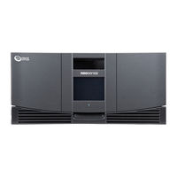
Neo Series 4000
Overland Storage Neo Series 4000 Manuals
Manuals and User Guides for Overland Storage Neo Series 4000. We have
3
Overland Storage Neo Series 4000 manuals available for free PDF download: Service Manual, Instructions Manual, Remove & Replace Instructions
Overland Storage Neo Series 4000 Service Manual (328 pages)
P/N 104241-xxx
Brand:
Overland Storage
| Category:
Storage
| Size: 10 MB
Table of Contents
Table of Contents
5
Chapter 1 Illustrated Parts Catalog
33
Introduction
33
Figure 1-1 Neo Series™ Library Modules
33
Mechanical Parts Exploded View
34
Figure 1-2 Neo Series 2000 Mechanical Parts
34
Chapter 1 Illustrated Parts Catalog
34
Table 1-1 Neo Series 2000 Mechanical Parts List
34
Figure 1-3 Neo Series 4000 Mechanical Parts
35
Table 1-2 Mechanical Spare Parts List
35
Electrical Parts Exploded View
36
Figure 1-4 Neo Series™ 2000 Electrical Parts
36
Table 1-3 Electrical Spare Parts List
36
Figure 1-5 Neo Series™ 4000 Electrical Parts
37
Table 1-4 Electrical Spare Parts List
37
Chapter 2 Servicing the Neo Series 2000
39
Introduction
39
Electrostatic Discharge Information
39
Preparation Procedures
39
Weight Warning
40
Emergency Magazine Removal
41
Figure 2-1 Manual Door Release
41
Figure 2-2 Magazine Removal
41
Library Covers Remove and Replace
42
Tabletop Model Cover Removal
42
Tabletop Model Cover Replacement
42
Library Inside Covers
42
Front Chassis Cover Removal
42
Figure 2-3 Tabletop Model Outer Skin Removal
42
Front Chassis Cover Replacement
43
Fan Cover Assembly Removal
43
Fan Cover Assembly Replacement
43
Power Supply Receiver Cover Removal
43
Figure 2-4 Cooling Fan Disconnect
43
Power Supply Receiver Cover Replacement
44
Figure 2-5 Tabletop Model Cover Removal
44
Parking the Shuttle Assembly Robotics for Service or Shipment
45
If the Library Is Operational
45
If the Library Is Not Operational
45
Figure 2-6 Shuttle Brake Release
46
Figure 2-7 Shuttle Assembly in Parked Position
46
Front Panel Remove and Replace
47
Front Panel Removal
47
Figure 2-8 Control Panel Board
47
Front Panel Replacement
48
Figure 2-9 Front Panel Removal
48
Figure 2-10 Routing Front Panel Cables
49
Figure 2-11 Powering up the Library
50
GUI Assembly Remove and Replace
51
GUI Assembly Removal
51
GUI Assembly Replacement
51
Figure 2-12 GUI Assembly Remove and Replace
51
Figure 2-13 Powering up the Library
52
Front Panel LED Remove and Replace
53
Front Panel LED Removal
53
Front Panel LED Replacement
53
Figure 2-14 Front Panel LED Remove
53
Figure 2-15 Powering up the Library
54
Front Panel Door Latch Remove and Replace
55
Front Panel Door Latch Removal
55
Figure 2-16 Front Panel Solenoids Cable Tie
55
Front Panel Door Latch Replacement
56
Figure 2-17 Front Panel Solenoid Remove and Replace
56
Figure 2-18 Powering up the Library
57
Drive Shoe Assembly Remove and Replace
58
Drive Shoe Assembly Removal
58
If the Library will Remain Operational
58
If the Library will Not be Operational
58
Drive Shoe Assembly Replacement
59
Figure 2-19 Removing a Tape Drive
59
Figure 2-20 Installing a Tape Drive
59
Figure 2-21 Powering up the Library
60
Elevator Opto Sensor Remove and Replace
61
Elevator Opto Sensor Removal
61
Figure 2-22 Access Plate Removal
61
Elevator Opto Sensor Replacement
62
Figure 2-23 Elevator Opto Sensor
62
Figure 2-24 Powering up the Library
63
Control Panel PCB Remove and Replace
64
Control Panel PCB Removal
64
Control Panel PCB Replacement
64
Figure 2-25 Control Panel PCB Remove and Replace
64
Figure 2-26 Powering up the Library
65
Magazine Interlock Solenoid Assembly
66
Magazine Interlock Solenoid Removal
66
Magazine Interlock Solenoid Replacement
66
Figure 2-27 Mail Slot Solenoid Remove and Replace
66
Figure 2-28 Powering up the Library
67
Library Controller Card Remove and Replace
68
Library Controller Removal
68
Library Controller Replacement
68
Figure 2-29 Library Controller Card Removal
68
Figure 2-30 Powering up the Library
69
Fibre Channel Option Card Remove and Replace
70
FCO Card Removal
70
FCO Card Replacement
70
Figure 2-31 FCO Card Removal
70
Figure 2-32 FCO Card Replacement
71
Figure 2-33 Powering up the Library
71
Power Supply Remove and Replace
72
Power Supply Removal
72
Power Supply Replacement
72
Figure 2-34 Power Supply Remove and Replace
72
Figure 2-35 Powering up the Library
73
Power Supply Receiver Remove and Replace
74
Power Supply Receiver Removal
74
Figure 2-36 Power Supply Receiver Remove and Replace
74
Power Supply Receiver Replacement
75
Figure 2-37 Powering up the Library
75
Card Cage Fan Remove and Replace
76
Card Cage Fan Removal
76
Figure 2-38 Card Cage Backplane Assembly
76
Figure 2-39 Card Cage Backplane Connector Access Plate Removal
77
Figure 2-40 Card Cage Fan Removal
77
Card Cage Fan Replacement
78
Figure 2-41 Powering up the Library
78
Card Cage/Back Plane Remove and Replace
79
Card Cage/Back Plane Removal
79
Card Cage/Back Plane Replacement
80
Figure 2-42 Card Cage Back Plane Assembly Removal
80
Figure 2-43 Powering up the Library
81
SCSI I/O Board and Plug Assembly
83
SCSI I/O Board and Plug Assembly Removal
83
SCSI I/O Board and Plug Assembly Replacement
84
Figure 2-44 SCSI I/O Board Removal
84
Figure 2-45 SCSI I/O Board / Plug Assembly
84
Figure 2-46 Powering up the Library
85
Drive Shield Remove and Replace
86
Drive Shield Removal
86
Tape Drive Shield Replacement
86
Figure 2-47 Tape Drive Shield Removal
86
Figure 2-48 Powering up the Library
87
Drive Guides Remove and Replace
88
Drive Guides Removal
88
Drive Guides Replacement
88
Figure 2-49 Drive Guide Removal
88
Figure 2-50 Powering up the Library
89
Magazine Opto Sensors
90
Magazine Opto Sensors Removal
90
Figure 2–51 Magazine Opto Sensor
90
Magazine Opto Sensors Replacement
90
Figure 2-52 Powering up the Library
91
Shuttle Assembly Track Sensor Remove and Replace
92
Shuttle Assembly Track Sensor Removal
92
Shuttle Assembly Track Sensor Replacement
93
Figure 2-53 Shuttle Assembly Track Sensor Removal
93
Figure 2-54 Powering up the Library
94
Shuttle Assembly Robotics Remove and Replace
95
Shuttle Assembly Robotics Removal
95
Shuttle Assembly Robotics Replacement
96
Figure 2-55 Shuttle Assembly Removal
96
Figure 2-56 Installing Flex Chain on Robot
97
Figure 2-57 Powering up the Library
98
Bar Code Reader Remove and Replace
99
Bar Code Reader Removal
99
Bar Code Reader Replacement
99
Figure 2-58 Bar Code Reader Removal
99
Figure 2-59 Powering up the Library
100
Flex Cable/Chain Assembly
101
Flex Cable/Chain Assembly Removal
101
Figure 2-60 Shuttle Assembly in Parked Position
102
Figure 2-61 J6 and J3 Removal
102
Figure 2-62 Flex Chain Removal
103
Flex Cable/Chain Assembly Replacement
104
Figure 2-63 Removing Flex Chain from Shuttle Assembly
104
Figure 2-64 Installing Flex Chain on Robot
105
Figure 2-65 Powering up the Library
106
Cable Support Rod
107
Cable Support Rod Removal
107
Cable Support Rod Replacement
107
Figure 2-66 Cable Support Rod Removal
107
Figure 2-67 Powering up the Library
108
Chapter 3 - Servicing the Neo Series 4000
109
Introduction
109
Electrostatic Discharge Information
109
Preparation Procedures
109
Weight Warning
110
Emergency Magazine Removal
111
Figure 3-1 Manual Door Release
111
Figure 3-2 Magazine Removal
112
Library Covers Remove and Replace
113
Tabletop Cover Removal
113
Tabletop Cover Replacement
113
Library Inside Covers
113
Front Chassis Cover Removal
113
Figure 3-3 Tabletop Model Tabletop Cover Removal
113
Front Chassis Cover Replacement
114
Fan Cover Assembly Removal
114
Fan Cover Assembly Replacement
114
Figure 3-4 Cooling Fan Disconnect
114
Power Supply Receiver Cover Removal
115
Power Supply Receiver Cover Replacement
115
Figure 3-5 Inside Covers Removal
115
Parking the Shuttle Assembly Robotics for Service or Shipment
116
If the Library Is Operational
116
If the Library Is Not Operational
116
Figure 3-6 Shuttle Brake Release
117
Figure 3-7 Shuttle Assembly in Parked Position
117
Front Panel Remove and Replace
118
Front Panel Removal
118
Figure 3-8 Front Panel Remove
119
Figure 3-9 Front Panel Removed
119
Front Panel Replacement
120
Figure 3-10 Applying Power
120
GUI Assembly Remove and Replace
121
GUI Assembly Removal
121
GUI Assembly Replacement
121
Figure 3-11 GUI Assembly Remove and Replace
121
Figure 3-12 Applying Power
122
Front Panel LED Remove and Replace
123
Front Panel LED Removal
123
Front Panel LED Replacement
123
Figure 3-13 LED Remove and Replace
123
Figure 3-14 Powering up the Library
124
Front Panel Latch Assembly Remove and Replace
125
Front Panel Latch Assembly Removal
125
Figure 3-15 Front Panel Latch Assembly
125
Front Panel Latch Assembly Replacement
126
Figure 3-16 Applying Power
126
Drive Shoe Assembly Remove and Replace
127
Drive Shoe Assembly Removal
127
If the Library will Remain Operational
127
If the Library will Not be Operational
127
Figure 3-17 Removing a Drive Shoe Assembly
128
Drive Shoe Assembly Replacement
129
Figure 3-18 Installing a Tape Drive
129
Control Panel PCB Remove and Replace
130
Control Panel PCB Removal
130
Figure 3-19 Control Panel PCB Mounting Screws
130
Control Panel PCB Replacement
131
Figure 3-20 Control Panel PCB Connections
131
Figure 3-21 Applying Power
132
Mail Slot Interlock
133
Mail Slot Interlock Removal
133
Figure 3-22 Control Panel PCB Cover Plate
133
Mail Slot Interlock Replacement
134
Figure 3-23 Magazine/Mail Slot Interlock Mounting Screws
134
Figure 3-24 Applying Power
135
Magazine Interlock Assembly
136
Magazine Interlock Removal
136
Figure 3-25 Control Panel PCB Cover Plate
136
Magazine Interlock Replacement
137
Figure 3-26 Interlock Mounting Screws
137
Figure 3-27 Applying Power
138
Library Controller Card Remove and Replace
139
Library Controller Removal
139
Figure 3-28 Library Controller Card Removal
139
Library Controller Replacement
140
Figure 3-29 Applying Power
140
Fibre Channel Option Card Remove and Replace
141
FCO Card Removal
141
FCO Card Replacement
141
Figure 3-30 FCO Card Removal
141
Figure 3-31 FCO Card Replacement
142
Figure 3-32 Apply Power
142
Partitioning Controller Card Remove and Replace
143
FCO Card Removal
143
FCO Card Replacement
143
Figure 3-33 FCO Card Removal
143
Figure 3-34 FCO Card Replacement
144
Figure 3-35 Apply Power
144
Power Supply Remove and Replace
145
Power Supply Removal
145
Figure 3-36 Power Supply Remove and Replace
145
Power Supply Replacement
146
Power Supply Receiver Remove and Replace
147
Power Supply Receiver Removal
147
Power Supply Receiver Replacement
148
Figure 3-37 Power Supply Reciever Remove and Replace
148
Figure 3-38 Applying Power
149
Card Cage Fan Remove and Replace
150
Card Cage Fans Removal
150
Upper Card Cage Fan Removal
150
Figure 3-39 Card Cage Backplane Connector Access Plate Removal
150
Figure 3-40 Card Cage Backplane Assembly
151
Figure 3-41 Upper Card Cage Fan Removal
151
Upper Card Cage Fan Replacement
152
Figure 3-42 Applying Power
152
Lower Card Cage Fan Removal
153
Figure 3-43 Card Cage Backplane Expansion PCB
153
Lower Card Cage Fan Replacement
154
Figure 3-44 Flex Cable Bracket Removal
154
Figure 3-45 Lower Card Cage Fan Removal
154
Figure 3-46 Applying Power
155
Lower Card Cage Fan Bracket Assembly
156
Fan Bracket Assembly Removal
156
Figure 3-47 Lower Card Cage Fan Bracket Removal
156
Fan Bracket Assembly Replacement
157
Figure 3-48 Lower Card Cage Bracket Assembly
157
Figure 3-49 Applying Power
158
Card Cage/Back Plane Remove and Replace
159
Card Cage/Back Plane Removal
159
Figure 3-50 Card Cage Back Plane Assembly Removal
160
Card Cage/Back Plane Replacement
161
Figure 3-51 Applying Power
162
Expansion Card Cage/Back Plane Remove and Replace
163
Expansion Card Cage/Back Plane Removal
163
Figure 3-52 Expansion Card Cage/Backplane
164
Expansion Card Cage/Back Plane Replacement
165
Figure 3-53 Applying Power
166
High Density SCSI I/O Boards and SCSI Connector Plate Assemblies
167
SCSI I/O Board and the SCSI Connector Plate Assembly Removal
167
Figure 3-54 SCSI I/O Board Removal
168
Figure 3-55 SCSI I/O Board Removal
168
SCSI I/O Board and the SCSI Connector Plate Assembly Replacement
169
Figure 3-56 Applying Power
169
Drive Divider Remove and Replace
170
Drive Divider Removal
170
Figure 3-57 Wire Harness Cover Plate
171
Figure 3-58 Drive Divider Removal
171
Drive Divider Replacement
172
Figure 3-59 Applying Power
172
Drive Guide Remove and Replace
173
Drive Guides Removal
173
Figure 3-60 Drive Guide Removal
173
Drive Guides Replacement
174
Figure 3-61 Applying Power
174
Upper Magazine Opto Sensors
175
Upper Magazine Opto Sensors Removal
175
Figure 3-62 Control Panel PCB Cover Plate
175
Upper Magazine Opto Sensors Replacement
176
Figure 3-63 Magazine Opto Sensors
176
Figure 3-64 Applying Power
177
Lower Magazine Opto Sensors
178
Lower Magazine Opto Sensor Removal
178
Figure 3-65 Control Panel PCB Cover Plate
178
Lower Magazine Opto Sensor Replacement
179
Figure 3-66 Magazine Opto Sensors
179
Figure 3-67 Applying Power
180
Shuttle Assembly Track Sensor Remove and Replace
181
Shuttle Assembly Track Sensor Removal
181
Shuttle Assembly Track Sensor Replacement
181
Figure 3-68 Track Sensor Removal
181
Figure 3-69 Applying Power
182
Elevator Opto Sensor Remove and Replace
183
Elevator Opto Sensor Removal
183
Figure 3-70 Backplane Access Cover
183
Elevator Opto Sensor Replacement
184
Figure 3-71 Pass Thru Sensor Remove
184
Figure 3-72 Powering up the Library
185
Shuttle Assembly Robotics Remove and Replace
186
Removing the Robot Shuttle and Track Base
186
Figure 3-73 Flex Cable, Carrier and Clip Removal
186
Figure 3-74 Rotate Track 90 Deg
187
Figure 3-75 Shuttle Brake Release
187
Figure 3-76 Removing Robotics Base
188
Replacing the Robot Shuttle and Base
188
Bar Code Reader Remove and Replace
190
Bar Code Reader Removal
190
Bar Code Reader Replacement
190
Figure 3-77 Bar Code Reader Removal
190
Figure 3-78 Applying Power
191
Front Vertical Axis Assembly Remove and Replace
192
Removing the Front Vertical Axis Assembly
192
Figure 3-79 Rotate Track 90 Deg
192
Figure 3-80 Shuttle Brake Release
193
Figure 3-81 Front Vertical Axis Assembly Screws
193
Figure 3-82 Front Vertical Axis Motor Cable
194
Figure 3-83 Front Vertical Axis Screws
194
Replacing the Front Vertical Axis Assembly
195
Figure 3-84 Shuttle Robot
195
Rear Vertical Axis Assembly Remove and Replace
196
Removing the Rear Vertical Axis Assembly
196
Figure 3-85 Flex Cable, Carrier and Clip Removal
196
Figure 3-86 Motor Cable / Mounting Screws
197
Figure 3-87 Rear Vertical Axis Screws Removed
197
Replacing the Rear Vertical Axis Assembly
198
Vertical Axis PCB Remove and Replace
199
Controller Board Removal
199
Figure 3-88 Vertical Controller Board
199
Replacing the Controller Board
200
Figure 3-89 Vertical Controller Board Removed
200
Figure 3-90 Applying Power
201
Robot Base Flex Cable Remove and Replace
202
Robot Base Flex Cable Removal
202
Figure 3-91 Access Panel / Flex Cable Bracket
203
Figure 3-92 Removing Fan from the Standoffs
203
Figure 3-93 Track Mounting Screws
204
Figure 3-94 Disconnecting Flex Cable at J1
204
Figure 3-95 Removing Flex Cable
205
Robot Base Flex Cable Replacement
206
Figure 3-96 Disconnecting Flex Cable at J12
206
Figure 3-97 Applying Power
207
Shuttle Assembly Flex Cable Remove and Replace
208
Robot Flex Cable Removal
208
Figure 3-98 Shuttle PCB
208
Figure 3-99 Flex Cable, Carrier and Clip Removal
209
Figure 3-100 Access Panel / Flex Cable Bracket
209
Rotating Track Flex Cable Replacement
210
Figure 3-101 Shuttle Flex Cable Connections
210
Figure 3-102 Applying Power
211
Chapter 4 Operation
213
Introduction
213
Front Panel
213
Figure 4-1 Library Front Panel
213
Figure 4-2 Magazine Door Mechanical Release
214
Magazine Doors
214
Figure 4-3 Library Indicators
215
Indicators
215
Neo Series 2000
215
Table 4-1 Indicators
215
Turning on the Libraries
215
Figure 4-4 Powering the Neo Series 2000
216
Figure 4-5 Powering the Neo Series 4000
216
Figure 4-6 Initialization Screen
217
Figure 4-7 Library Default Screen
217
Initialization Screen
217
Library Default Screen
217
Front Panel and Media Security Locks
218
Neo Series 4000
216
Figure 4-8 Library Password Levels
218
Passwords Screen
218
Host System
219
Library Display Screens and Options
220
Technical Support Information Option
220
Figure 4-9 Technical Support Information Screen
220
Access Mail Slot Option (Left Magazine Only)
221
Access Magazine Option
221
Figure 4-10 Access Mail Slot Screen
221
Move Media
222
Figure 4-11 Access Magazine Screen
222
Figure 4-12 Move Media Screen
222
LCD Contrast Controls
223
Figure 4-13 Move Media Screen (Source)
223
Figure 4-14 Move Media Screen (Destination)
223
Power
224
Figure 4-15 Power down Initiation Screen
224
Status
225
Online
225
Figure 4-16 Neo Series Status Screen
225
Menu Selections
226
Figure 4-17 Menu Screen
226
Figure 4-18 View Library Options Screen (Initial Screen)
227
Library Options
227
Table 4-2 View Library Options
227
View System Data
227
Figure 4-19 View SCSI Options Screen (Initial Screen)
230
SCSI Options
230
Table 4-3 View SCSI Options
230
Figure 4-20 View Network Options Screen
232
Library Info
232
Network Options
232
Table 4-4 View Network Options
232
Cartridge Map
233
Edit Options
233
Figure 4-21 View Library Info Screen
233
Figure 4-22 Cartridge Map
233
Figure 4-23 Edit Library Options Screen
234
Figure 4-24 Edit SCSI Options Screen
234
Library
234
Scsi
234
Figure 4-25 Edit Network Options Screen
235
Figure 4-26 Edit Passwords Options Screen
235
Utilities
236
Network
235
Passwords
235
Figure 4-27 Security Level Screen
236
Security Level
236
Inserting and Removing Tape Cartridges
237
Removing Magazines
237
Inserting Cartridges into a Magazine
237
Figure 4-28 Removing Tape Cartridge Magazines
237
Using the Mail Slot (Left Magazines Only)
238
Figure 4-29 Tape Magazine with Tape Cartridges Installed
238
Barcode Labels
239
Figure 4-30 Left Magazine Mail Slot
239
Figure 4-31 Barcode Label Installation
239
Chapter 5 Troubleshooting
241
Introduction
241
Platform Problems
241
Error Recovery
242
Figure 5-1 Troubleshooting Flow Chart
242
Error Recovery Procedures
243
Table 5-1 Error Recovery Procedures
243
Fault Symptom Codes (Fscs)
244
Chapter 5 Troubleshooting
244
Table 5-2 Fault Symptom Codes
244
Chapter 6 - Connectors, Switches and Indicators
253
Introduction
253
Neo Series 2000 Connectors
253
Library Controller Board
253
Figure 6-1 Library Controller Board
253
Table 6-1 Library Controller Board Connectors
253
Control Panel Board
254
Figure 6-2 Control Panel Board
254
Table 6-2 Control Panel Board Connectors
254
Card Cage/Backplane Assembly
255
Figure 6-3 Card Cage/Backplane Assembly
255
Table 6-3 Card Cage/Backplane Assembly Connectors
255
Shuttle Assembly Board
256
Figure 6-4 Shuttle Assembly Board
256
Table 6-4 Shuttle Assembly Board Connectors
256
SCSI I/O Board
257
Figure 6-5 SCSI I/O Board (Bottom Side)
257
Table 6-5 SCSI I/O Board Connectors (Bottom Side)
257
Figure 6-6 SCSI I/O Board (Top Side)
258
Table 6-6 SCSI I/O Board Connectors (Top Side)
258
Hot Swap Library Board
259
Figure 6-7 Hot Swap Library Board
259
Table 6-7 Hot Swap Library Board
259
Neo Series 4000 Connectors
260
Library Controller Board
260
Figure 6-8 Library Controller Board
260
Table 6-8 Library Controller Board Connectors
260
Control Panel Board
261
Figure 6-9 Control Panel Board
261
Table 6-9 Control Panel Board Connectors
261
Card Cage/Backplane Board
262
Figure 6-10 Card Cage/Backplane Board
262
Table 6-10 Card Cage/Backplane Board Connectors
262
Card Cage/Backplane Expansion Board
263
Figure 6–11 Card Cage/Backplane Expansion Board
263
Table 6-11 Card Cage/Backplane Expansion Board Connectors
263
Shuttle Assembly Board
264
Figure 6-12 Shuttle Assembly Board
264
Table 6-12 Shuttle Assembly Board Connectors
264
Mono Track Interface Board
265
Figure 6-13 Mono Track Interface Board
265
Table 6-13 Mono Track Interface Board Connectors
265
Vertical Axis Assembly Board
266
Figure 6-14 Vertical Axis Assembly Board
266
Table 6-14 Vertical Axis Assembly Board Connectors
266
Upper and Lower SCSI I/O Boards
267
Figure 6-15 SCSI I/O Board (Bottom Side)
267
Table 6-15 SCSI I/O Board Connectors (Bottom Side)
267
Figure 6-16 SCSI I/O Board (Top Side)
268
Table 6-16 SCSI I/O Board Connectors (Top Side)
268
Hot Plug Library Board
269
Figure 6-17 Hot Plug Library Board
269
Table 6-17 Hot Plug Library Board
269
Switches
270
Library Controller Board
270
Power Supply
270
Figure 6-18 Library Controller Board Mode Switch
270
Figure 6-19 Power Supply (S) Power On/Off Switch
270
LED Indicators
271
Power Supply(S) Power-On LED Indicator
271
Library Status LED Indicator
271
Figure 6-20 Power Supply(S) Power-On LED Indicator
271
Figure 6-21 Power Supply(S) Power-On LED Indicator
271
Appendix A - Specification
273
Table A-1 Hardware Specification
273
Hardware Specification
274
Environmental Specifications
275
Safety
275
Table A-2 Safety Specification
275
Electromagnetic Emissions
276
Table A-3 Electromagnetic Emissions Specification
276
Electrostatic Discharge
277
Temperature, Humidity and Altitude
277
Shock
277
Table A-4 Electrostatic Discharge Specification
277
Table A-5 Temperature Humidity and Altitude Specification
277
Table A-6 Electromagnetic Emissions Specification
277
Vibration
278
Table A-7 Vibration Specification
278
Primary Power
279
Voltage Limits
279
Frequency Limits
279
Power Requirements
279
Table A-8 Current
279
Sag / Surge Protection
280
Power Line Disturbance
280
Table A-9 Sag / Surge Protection
280
Table A-10 Power Line Disturbance
280
Cooling
281
FCC Notice
282
Japanese Voluntary Control Council for Interference (VCCI
282
Translation
282
Installation Considerations
283
Rack Mounting
283
Input Supply
283
Grounding
283
Appendix B Vertical Axis Alignment
287
Alignment Procedure
287
Figure B-1 Applying Power
287
Figure B-2 Initialization Screen
288
Figure B-3 Menu Screen
288
Figure B-4 Diagnostics Screen
289
Figure B-5 Vertical Axis Calibration Screen
289
Figure B-6 Mounting Screw Sequence
290
Figure B-7 Final Calibration Screen
291
Figure B-8 Initial Calibration Screen
291
Figure B-9 Main Screen
292
Appendix C Elevator Assembly Installation
293
Introduction
293
Mechanical Installation
293
Planning Your Installation
294
Positioning Your Modules and the Elevator
294
Verify Minimum Firmware Level
294
Figure C-1 Powering up the Library
295
Neo Series Router
296
Router Installation
296
Figure C-2 Typical Router
296
Figure C-3 Router Installed
297
Installing the Elevator Assembly
298
Figure C-4 Drive Shoe/Blank Panel Removal
299
Figure C-5 Cover Plate Removal
299
Figure C–6 Installing the Elevator Assembly
301
Figure C-7 Installing a Tape Drive
302
Elevator Assembly Extension
303
Elevator Assembly Required Tools
303
Orientation of Parts During Assembly
304
Preparing to Assemble the Elevator
304
Figure C-8 Factory Assembled Elevator Assembly
304
Figure C-9 Elevator Bottom Plate
305
Figure C-10 Media Elevator Car
305
Figure C-11 Tensioner Ramp/Idler Pulley Zero Point
306
Figure C-13 Tensioner Ramp/Idler Pulley
307
Figure C-14 Elevator Extension Alignment
307
Figure C-15 Tie Bar Installation
308
Table C-1 Timing Belt Lengths
308
Figure C-16 Timing Belt Installation Base Section
309
Figure C-17 Timing Belt Installation
309
Figure C-18 Timing Belt to Belt Block
310
Figure C-19 Assembled Elevator and Extension
311
Neo Series Module Configuration
312
Configuring Modules for Elevator Application
312
Configuring the Primary Master Module
312
Figure C-20 Powering up the Library
312
Figure C-21 Neo Main GUI Display
313
Figure C-22 Menu Screen
313
Figure C-23 Module Configuration Select Screen
314
Figure C-24 Module Configuration Screen
314
Figure C-25 Module Configuration Confirm
315
Figure C-26 Primary Master Screen
315
Configuring Slave Modules
316
Figure C-27 Neo Main GUI Display
316
Figure C-28 Menu Screen
316
Figure C-29 Module Configuration Select Screen
317
Figure C-30 Module Configuration Screen
317
Figure C-31 Module Configuration Confirm
317
Figure C-32 Typical Configured Slaves
318
Cabling and Interface Connections
319
Figure C-33 Typical Library Cabling
319
Figure C-34 Powering up the Library
320
Verifying Firmware Level of the Slave Modules
321
Fail-Over Operation
322
Cabling Considerations for Fail-Over Operation
322
Fail-Over Initiation
323
Fail-Over Terms
322
Introduction
322
Local Fail-Over to Secondary Master Initiation
323
Figure C-35 Secondary Master Screen
323
Figure C-36 Secondary Master Menu Screen
324
Figure C-37 Secondary Master Maintenance Screen
324
Remote Fail-Over to Secondary Master Initiation
325
Restoring Normal Operation
326
Local Fail-Over to Primary Master
326
Figure C-38 Secondary Master Screen
326
Figure C-39 Secondary Master Menu Screen
327
Figure C-40 Secondary Master Maintenance Screen
327
Remote Failover to Primary Master
327
Advertisement
Overland Storage Neo Series 4000 Instructions Manual (31 pages)
Brand:
Overland Storage
| Category:
Storage
| Size: 8 MB
Table of Contents
Table of Contents
3
Introduction
6
Tabletop Unit
7
Figure - 4, Removing a Tape Drive Assembly NEO 2000
8
Figure - 5, Tabletop Model Outer Skin Replacement NEO 2000
9
Figure - 8, V.I.A. Card Replacement NEO 2000
10
Rack Mounted Unit
11
Figure - 12, Power Supply Removal NEO 2000
12
Figure - 14, Rack Mount Screws NEO 2000
13
Figure - 16, Changing the Inner Slide Members NEO 2000
14
Install the Xchangenow Library
15
Figure - 20, V.I.A. Card Replacement NEO 2000
16
Figure - 22, Power Supply Replacement NEO 2000
17
Neo 4000
18
Tabletop Unit
19
Figure - 26, V.I.A. Card Removal NEO 4000
20
Figure - 28, Power Supply Removal NEO 4000
21
Install the Xchangenow Tabletop Library
22
Figure - 31, Tape Drive Replacement NEO 4000
23
Figure - 33, Powering on the Library
24
Rack Mounted Unit
25
Figure - 34, V.I.A. Card Removal NEO 4000
25
Figure - 36, Rack Mount Screws NEO 4000
26
Figure - 38, Changing the Inner Slide Members NEO 4000
27
Install the Xchangenow Library
28
Figure - 42, V.I.A. Card Replacement NEO 4000
29
Figure - 44, Tape Drive Replacement NEO 4000
30
Overland Storage Neo Series 4000 Remove & Replace Instructions (2 pages)
Card Cage Fan
Brand:
Overland Storage
| Category:
Fan
| Size: 0 MB
Table of Contents
Unpacking the Spare
1
Electrostatic Discharge Information
1
Replacing the Upper Fan (NEO 2000/4000)
1
Install the New Fan
1
Removing the Old Fan
2
Installing the New Fan
2
Replacing the Lower Fan (NEO 4000)
2
Additional Help
2
Advertisement
Advertisement
Related Products
Overland Storage Neo Series Library
Overland Storage NEO S-Series
Overland Storage NEO 8000
Overland Storage NEO 8000E
Overland Storage Neo Series 2000
Overland Storage NEO 200S
Overland Storage NEO 400S
Overland Storage NEO 2000e
Overland Storage NEO 4000e
Overland Storage Neo 8135
Overland Storage Categories
Storage
Server
Chassis
Network Storage Server
DC Drives
More Overland Storage Manuals
Login
Sign In
OR
Sign in with Facebook
Sign in with Google
Upload manual
Upload from disk
Upload from URL