Table of Contents
Advertisement
Quick Links
Advertisement
Table of Contents

Related Manuals for FibroLAN Falcon-RX/812/G/A

Summary of Contents for FibroLAN Falcon-RX/812/G/A
- Page 1 Falcon R-Class User Guide Falcon-RX Software version 8.0.20 www.fibrolan.com...
- Page 2 Falcon R-Class | User Guide proprietary information This document contains information, which is proprietary to Fibrolan Ltd. No part of its contents may be used, copied, disclosed or conveyed to a third party in any manner whatsoever without prior written permission from Fibrolan Ltd.
-
Page 3: Table Of Contents
Falcon R-Class | User Guide Table of Contents R Class series overview ....................8 Falcon-RX ....................... 8 Physical Description ....................8 Falcon-RX/812/G ..................... 8 Models List ......................... 9 Typical Applications ..................... 9 5G Fronthaul & Backhaul Convergence ............. 9 IIoT Campus deployment ................10 Block Diagram ...................... - Page 4 Falcon R-Class | User Guide Private VLANs (PVLANs) ................56 VCL ......................58 Voice VLAN ....................63 Multicast VLAN Registration (MVR) ..............66 Quality of Service (QoS) .................... 73 QoS Ingress Port Classification ............... 73 QoS Ingress Port Policers ................75 QoS Ingress Queue Policers ................
- Page 5 Falcon R-Class | User Guide PTP Slave Table ..................174 4.13 Synchronous Ethernet (SyncE) ................. 176 Overview ....................176 SyncE Port Configuration ................177 SyncE Port Monitoring ................. 179 4.14 External Sync Ports Configuration ................181 External Status ................... 181 4.15 Spanning Tree ......................
- Page 6 Falcon R-Class | User Guide 4.23 sFlow Consideration ....................251 sFlow Configuration displays ................ 251 sFlow Statistics ................... 253 4.24 UDLD Configuration ....................255 UDLD Port Configuration................255 Detailed UDLD Status for Port 1 ..............256 General Introduction ....................257 System Information ..................
- Page 7 Falcon R-Class | User Guide Ping IPv4 ....................295 Ping IPv6 ....................297 Link OAM MIB Retrieval ................298 VeriPHY Cable Diagnostics ................299 Restart Device ......................301 Factory Defaults ...................... 301 Software Management .................... 302 Software Image Select ................302 Configuration Management ..................
-
Page 8: R Class Series Overview
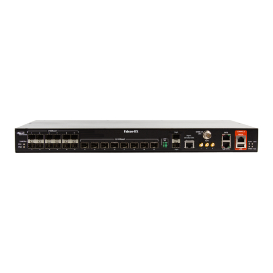
Falcon R-Class | User Guide Introduction 1.1 R Class series overview Falcon-RX Falcon-RX is a high performance, 5G xHaul Timing Aware O-RAN Switch & PTP Grandmaster. It is a high capacity, low latency transport and high precision synchronization device that enables 5G RAN operation at its optimal throughput, on both telecom and enterprise environments. -
Page 9: Models List
Falcon R-Class | User Guide 1.3 Models List Table 1-2: Falcon-RX models list Model Part Description Falcon-RX/812/G/A 7160 Timing Aware xHaul Switch, 12x10G (SFP+), 8x25G (SFP28) ports, Advanced Timing spec w/ GNSS Rx, 1 removable AC power supply (FPS10012/A) Falcon-RX/812/G/D 7161... -
Page 10: Iiot Campus Deployment
Falcon R-Class | User Guide IIoT Campus deployment Modern industrial campuses and factories are being designed to accommodate high level of automation and mobility in production, which dictates specific requirement for synchronization. In such environment where, man and machine coexist and work together side by side all actions must be coordinated and mutually aware. -
Page 11: Block Diagram
Falcon R-Class | User Guide System Description 2.1 Block Diagram Figure 2-1: R Class functional block diagram... -
Page 12: R Class Series Key Features
Falcon R-Class | User Guide 2.2 R Class series key features • LTE/5G xHaul Transport and Timing RAN switch • Integrated PTP Grandmaster • Compatible with O-RAN architectures • High capacity, low latency • Extensive Sync and Timing with SyncE and PTP (PTRC/GM, BC, TC) •... - Page 13 Falcon R-Class | User Guide • MEF 22.1: Mobile Backhaul Phase 2 • Per port / queue policing • Per port / queue shaping • Per Port Counters: The R Class models support frame and byte counters per port. • Link OAM (IEEE802.3ah) and Service OAM (based on IEEE 802.1ag, ITU-T Y.1731) •...
-
Page 14: Quick Setup Outline
(192.168.1.90) Establish management access via SSH, Telnet or Web GUI (4.1.2). For a general configuration procedure please refer to the Getting Started Quick Guide located at www.Fibrolan.com (Resources > Documents > Quick Guides). Note: Remote management requires basic IP configuration. -
Page 15: Console Connection And Configuration
Fibrolan support (International: support@Fibrolan.com; North America: Us-info@Fibrolan.com) Initial IP address settings This first configuration is done via the console; it enables the switch to connect to the IP network. Once the unit IP address is set via console, the system can be accessed through Web, Telnet, SSH or any other management options. -
Page 16: Web Gui
Falcon R-Class | User Guide 3.3 Web GUI The Web management is accessed by setting the required IP address in the URL Browser. When accessing the devices via the Web interface, its initial Port State Overview window is displayed. as shown below. - Page 17 Falcon R-Class | User Guide ④ Dynamic configuration section: Displays detailed data for the selected from one of the functionality menus. • Auto-refresh: Check this box to refresh the page automatically. Automatic refresh occurs every 3 seconds • Refresh: Click to refresh the page.
-
Page 18: Overview
Falcon R-Class | User Guide Functional Description 4.1 Overview This section provides introduction to the R Class series functionality and instructions for configuration and monitoring. The configuration and monitoring functionalities can be accessed via various management interfaces. Sections 4 demonstrates the configuration various functions and setting mainly using the Web interface. -
Page 19: System Information
Falcon R-Class | User Guide • ACL:(Access Control List) The ACL can drop a frame or redirect it to a specific port • MAC address and VLAN: The standard Ethernet switch forwarding – a frame is forwarded by searching the learn-table and sending it to the port where the MAC-address + VLAN was learnt. If the address is not found, or the frame is a broadcast frame it will be sent to all the other member ports of the VLAN. - Page 20 Falcon R-Class | User Guide Web GUI: Configuration > System > IP Figure 4-3: IP Configuration Table 4-2: IP Configuration Parameters IP Configuration- Basic Settings Mode Configure whether the IP stack should act as a Host or a Router. In Host mode, IP traffic between interfaces will not be routed.
-
Page 21: Ip Interfaces
Falcon R-Class | User Guide IP Interfaces Web GUI: Configuration > System > IP Figure 4-4: IPv4 / IPv6 Configuration Table 4-3: IP Interfaces Parameters Delete Select this option to delete an existing IP interface VLAN The VLAN associated with the IP interface. Only ports in this VLAN will be able to access the IP interface. - Page 22 Falcon R-Class | User Guide IPv4 Address The IPv4 address of the interface in dotted decimal notation. If DHCP enabled, this field configures the fallback address. The field may be left blank if IPv4 operation on the interface is not desired - or no DHCP fallback address is desired.
-
Page 23: Ip Routes
Falcon R-Class | User Guide IP Routes Web GUI: Configuration > System > IP Figure 4-5: IP Routes Table 4-4: IP Routes Parameters Delete Select this option to delete an existing IP route. Network The destination IP network or host address of this route. Valid format is dotted decimal notation or a valid IPv6 notation. - Page 24 Falcon R-Class | User Guide 4.3.5.1 NTP Client Configuration The NTP client configuration allows the switch to set the IP address of up to 5 different NTP servers as a time source. Additionally, server polling interval and encryption options can be configured. Maximum and minimum polling values in seconds are between 8-131072(approximately 36.4 hours).
- Page 25 Falcon R-Class | User Guide 4.3.5.2 NTP Server Configuration Falcon-RX NTP server function allows it to propagate the SyncCenter time via NTP to other clients in the network. The server supports three operational modes: Unicast, Broadcast and Multicast. Allowed polling rate and encryption can be set for each mode separately. Figure 4-8: NTP Server Configuration Table 4-6: NTP Server Configuration Parameters Client Configuration...
-
Page 26: Time Zone
Falcon R-Class | User Guide Time Zone This section allows us to configure the Time Zone. Time Zone Configuration Daylight Saving Time Configuration. Start Time /End Time/Offset settings. Web GUI: Configuration > System > Time Figure 4-9: Time Zone Configuration Table 4-7: Time Zone Configuration Parameters Time Zone Configuration Time Zone... - Page 27 Falcon R-Class | User Guide Figure 4-11: Time Settings displays Table 4-9: Time Settings Parameters Recurring Configurations Week - Select the starting week number. Start time settings Day - Select the starting day. Month - Select the starting month. Hours - Select the starting hour. Minutes - Select the starting minute.
-
Page 28: System Log Configuration
Falcon R-Class | User Guide System Log Configuration Configure System Log on this section. Web GUI: Configuration > System > Log Figure 4-12: System Log Configuration displays Table 4-10: System Log Configuration Parameters System Log Configuration Server Mode Indicates the server mode operation. When the mode operation is enabled, the syslog message will send out to syslog server. -
Page 29: Events
Falcon R-Class | User Guide Events This page allows the user to change (enable/disable) and their corresponding interfaces to the current events configuration. Web GUI: Configuration > System > Events Figure 4-13: Events Configuration Table 4-11: Events Configuration Parameters Event Index Event Unique Name of the Event. -
Page 30: Ports Configuration And Monitoring
Falcon R-Class | User Guide 4.4 Ports Configuration and Monitoring This section shows current port configurations. Ports may be configured here. Ports are also monitored here. Web GUI: Configuration > System > Ports Figure 4-14: Port Configuration Table 4-12: Port Configuration Parameters Port This is the logical port number for this row. - Page 31 Falcon R-Class | User Guide Cable Type AutoSFP interface in "auto" mode. Automatic SerDes tuning for optical and DAC-3m cables. DAC-1mSFP interface in "DAC-1m" mode. Manual SerDes tuning specifically for DAC-1m cables. DAC-2mSFP interface in "DAC-2m" mode. Manual SerDes tuning specifically for DAC-2m cables.
-
Page 32: Port State
Falcon R-Class | User Guide Description Indicates the description of the port. Maximum length of the Port description String is 64. Port description can be null. When port description is not null, it cannot contain space. Frame Length Check Configures if frames with incorrect frame length in the EtherType/Length field shall be dropped. -
Page 33: Sfp Information
Falcon R-Class | User Guide SFP Information This section shows SFP Information. Web GUI: Monitor > Ports > SFP Info Figure 4-16: SFP information Table 4-13: SFP Information Parameters Vendor # Indicates vendor's name. Part # Indicates part number. Type Indicates module Type. -
Page 34: Sfp Monitoring
Falcon R-Class | User Guide Web GUI: Monitor > Ports > SFP Op Range Figure 4-17: Operational Range Table 4-14: SFP Operational Range Parameters Port The physical port in which the SFP is installed Status The status of the SFP port: grey=unplugged Red=when SFP is plugged and operational;... -
Page 35: Traffic Overview
Falcon R-Class | User Guide Temperature Module's internal temperature. Bias Current Module's transmitter bias current [mA]. Supply voltage Module's supply voltage [V]. Note: Green indicator implies that the parameters are within the allowed range Traffic Overview Web GUI: Monitor > Ports > Traffic Overview Figure 4-19: Port Statistics Table 4-16: Port Statistics Overview Parameters Port #... -
Page 36: Qos Statistics
Falcon R-Class | User Guide QoS Statistics Web GUI: Monitor > Ports > Traffic Overview Figure 4-20: Queuing Counters Display Table 4-17: Queuing Counters Parameters Port The logical port for the settings contained in the same row. There are QoS queues per port. Q0 is the lowest priority queue. Rx/Tx The number of received and transmitted packets per queue. -
Page 37: Detailed Port Statistics
Falcon R-Class | User Guide Table 4-18: QoS Control List Status Parameters User Indicates the QCL user. Indicates the index of QCE. Frame type Indicates the type of frame to look for incoming frames. Possible frame types are: • Any: Match any frame type. •... - Page 38 Falcon R-Class | User Guide Web GUI: Monitor > Ports > QCL Status Figure 4-22: Detailed Port Statistics Table 4-19: Detailed Port Statistics Parameters Receive Total and Transmit Total Rx and Tx Packets The number of received and transmitted (good and bad) packets. Rx and Tx Octets The number of received and transmitted (good and bad) bytes.
-
Page 39: Green Ethernet
Falcon R-Class | User Guide Receive and Transmit Queue Counters The number of received and transmitted packets per input and output queue. Receive Error Counters Rx Drops The number of frames dropped due to lack of receives buffers or egress congestion. -
Page 40: Thermal Protection
Falcon R-Class | User Guide When a port is powered down for saving power, outgoing traffic is stored in a buffer until the port is powered up again. Because there are some overheads in turning the port down and up, more power can be saved if the traffic can be buffered up until a large burst of traffic can be transmitted. -
Page 41: Mac Learning Table
Falcon R-Class | User Guide 4.5 MAC Learning Table This section details the MAC Learn Table functionality. Switching of frames is based upon the DMAC address contained in the frame. The switch builds up a table that maps MAC addresses to switch ports for knowing which ports the frames should be delivered to (Based upon the DMAC address in the frame). - Page 42 Falcon R-Class | User Guide Table 4-20: MAC Address Table Configuration Parameters Aging Configuration Aging Configuration By default, dynamic entries are removed from the MAC after 300 seconds. This removal is also called aging. Configure aging time by entering a value here in seconds; for example, Age Time: seconds.
-
Page 43: Monitoring The Mac Address Table
Falcon R-Class | User Guide Static MAC Table Configuration Static Table The static entries in the MAC table are shown in this table. Configuration The static MAC table can contain up to a maximum 64 entries. The MAC table is sorted first by VLAN ID and then by MAC address. Delete: Check to delete the entry. - Page 44 Falcon R-Class | User Guide The Start from MAC address and VLAN input fields allow the user to select the starting point in the MAC Table. Clicking the Refresh button will update the displayed table starting from that or the closest next MAC Table match.
-
Page 45: Vlans And Provider Bridges
Falcon R-Class | User Guide 4.6 VLANs and Provider Bridges Virtual LAN, commonly known as VLAN, is a group of hosts with a common set of requirements that communicate as if they were attached to the same LAN, regardless of their physical location. A VLAN has the same attributes as a physical LAN, but allows for end stations to be grouped together even if they are not located on the same LAN segment. - Page 46 Falcon R-Class | User Guide Table 4-22: Global VLAN Configuration Parameters Global VLAN Configuration Allowed Access This field shows the allowed Access VLANs, i.e., it only affects ports VLANs configured as Access ports (the default port mode). Ports in other modes are members of all VLANs specified in the Allowed VLANs field (Ports in Trunk and Hybrid mode).
- Page 47 Falcon R-Class | User Guide Figure 4-26: VLAN Port Configuration Table 4-23: VLAN Port Configuration Table Parameters Global VLAN Configuration Allowed Access VLANs This field shows the allowed Access VLANs, i.e., it only affects ports configured as Access ports . Ports in other modes are members of all VLANs specified in the Allowed VLANs field.
- Page 48 Falcon R-Class | User Guide 4.By default, all frames but frames classified to the Port VLAN (a.k.a. Native VLAN) get tagged on egress. Frames classified to the Port VLAN do not get C-tagged on egress. 5.Egress tagging can be changed to tag all frames, in which case only tagged frames are accepted on ingress.
- Page 49 Falcon R-Class | User Guide gets classified to the Port VLAN. If frames must be tagged on egress, they will be tagged with the custom S-tag. Ingress Filtering Hybrid ports allow for changing ingress filtering. Access and Trunk ports always have ingress filtering enabled. If ingress filtering is enabled (checkbox is checked), frames classified to a VLAN that the port is not a member of get discarded.
- Page 50 Falcon R-Class | User Guide VLAN User Various internal software modules may use VLAN services to configure VLAN memberships on the fly. The drop-down list on the right allows for selecting between showing VLAN memberships as configured by an administrator (Admin) or as configured by one of these internal software modules. The "Combined"...
- Page 51 Falcon R-Class | User Guide 4.6.1.3 VLAN Port Status for Combined users This section provides VLAN Port Status. VLAN USER Various internal software modules may use VLAN services to configure VLAN port configuration on the fly. The drop-down list on the right allows for selecting between showing VLAN memberships as configured by an administrator (Admin) or as configured by one of these internal software modules.
-
Page 52: Vlan Membership Status For Combined Users
Falcon R-Class | User Guide Untagged VLAN ID If Tx Tag is overridden by the selected user and is set to Tag or Untag UVID, then this field will show the VLAN ID the user wants to tag or untag on egress. -
Page 53: Vlan Translation
Falcon R-Class | User Guide Web GUI: Monitor > VLANs > Membership Figure 4-29: VLAN Membership Status for Combined Users Table 4-26: VLAN Membership Status for Combined users Parameters VLAN ID VLAN ID for which the Port members are displayed. VLAN Name VLAN Name for which the Port members are displayed. - Page 54 Falcon R-Class | User Guide Web GUI: Configuration > VLAN Translation > Port to Group Configuration Figure 4-30: VLAN Translation Port Configuration Table 4-27: Port to Group mapping Table Parameters Port The Port column shows the list of ports for which you can configure the VLAN Translation Mapping Group.
- Page 55 Falcon R-Class | User Guide 4.6.3.2 VLAN Translation Mapping Table This section allows you to create mappings of VLANs -> Translated VLANs and organize these mappings into global Groups. Web GUI: Configuration > VLAN Translation > VLAN Translation Mapping Figure 4-31: VLAN Translation Mapping Table Table 4-28: VLAN Translation Mapping Table parameters Group ID The VLAN Translation mappings are organized into Groups, identified by the...
-
Page 56: Provider Bridges (Qinq)
Falcon R-Class | User Guide Modification You can modify each VLAN Translation mapping in the table using the Buttons following buttons: : Edits the mapping row. : Deletes the mapping. : Adds a new mapping. Provider Bridges (QinQ) The use of an extra VLAN header (service provider tag) as part of the Ethernet frame header to provide differentiation between traffic flows (whether a separate service, or a separate customer) is common in service provider networks. - Page 57 Falcon R-Class | User Guide A port must be a member of both a VLAN and a Private VLAN to be able to forward packets. By default, all ports are VLAN unaware and members of VLAN 1 and Private VLAN 1. A VLAN unaware port can only be a member of one VLAN, but it can be a member of multiple Private VLANs.
-
Page 58: Vcl
Falcon R-Class | User Guide Figure 4-33: Private VLAN Port Isolation Configuration Table 4-30: Private VLAN Port Isolation Configuration Parameters Port Members A check box is provided for each port of a private VLAN. When checked, port isolation is enabled for that port. When unchecked, port isolation is disabled for that port. - Page 59 Falcon R-Class | User Guide 4.6.6.2 Protocol based VLAN This section allows you to add a new Protocol to a Group Name (each protocol can be part of only one Group) mapping entries as well as allow you to see and delete already mapped entries for the There are two subjects: •...
- Page 60 Falcon R-Class | User Guide protocol running on top of SNAP; if OUI is an OUI for a particular organization, the protocol ID is a value assigned by that organization to the protocol running on top of SNAP. In other words, if the value of OUI field is 00-00-00 then the value of PID will be etype (0x0600-0xffff) and if the value of OUI is other than 00-00-00 then valid values of PID will be any value between...
- Page 61 Falcon R-Class | User Guide Table 4-33: Group Name to VLAN Mapping Table parameters Delete To delete a Group Name to VLAN mapping, check this box. The entry will be deleted from the switch during the next Save. Group Name A valid Group Name is a string, at the most 16 characters long, which consists of a combination of alphabets (a-z or A-Z) and integers (0-9) with no special characters allowed.
- Page 62 Falcon R-Class | User Guide Table 4-34: IP Subnet based VLAN Membership Configuration parameters Delete To delete a mapping, check this box and press save. The entry will be deleted in the stack. IP Address Indicates the subnet's IP address (Any of the subnet's host addresses can be also provided here, the application will convert it automatically).
-
Page 63: Voice Vlan
Falcon R-Class | User Guide Voice VLAN The Voice VLAN feature enables voice traffic forwarding on the Voice VLAN, then the switch can classify and schedule network traffic. It is recommended that there be two VLANs on a port - one for voice, one for data. - Page 64 Falcon R-Class | User Guide 4.6.7.2 Port Configuration Web GUI: Configuration > Voice VLAN > Configuration Figure 4-39: Port Configuration display Table 4-36: Port Configuration parameters Port Configuration Port The logical port for the settings contained in the same row. Mode Indicates the Voice VLAN port mode.
- Page 65 Falcon R-Class | User Guide Port Configuration Security Indicates the Voice VLAN port security mode. When the function is enabled, all non-telephonic MAC addresses in the Voice VLAN will be blocked for 10 seconds. Possible port modes are: Enabled: Enable Voice VLAN security mode operation. Disabled: Disable Voice VLAN security mode operation.
-
Page 66: Multicast Vlan Registration (Mvr)
Falcon R-Class | User Guide Table 4-37: Voice VLAN OUI Table parameters Delete Check to delete the entry. It will be deleted during the next save. Telephony A telephony OUI address is a globally unique identifier assigned to a vendor by IEEE. It must be 6 characters long and the input format is "xx-xx-xx"... - Page 67 Falcon R-Class | User Guide Table 4-38: MVR Configuration parameters MVR Mode Enable/Disable the Global MVR. The Unregistered Flooding control depends on the current configuration in IGMP/MLD Snooping. It is suggested to enable Unregistered Flooding control when the MVR group table is full. 4.6.8.2 VLAN Interface Setting Web GUI: Configuration >...
- Page 68 Falcon R-Class | User Guide membership. The value is in units of tenths of a second. The range is from 0 to 31744. The default LLQI is 5 tenths or one-half second. Interface Channel When the MVR VLAN is created, select the IPMC Profile as the channel Profile filtering condition for the specific MVR VLAN.
- Page 69 Falcon R-Class | User Guide 4.6.8.3 Immediate Leave Setting Web GUI: Configuration > MVR Figure 4-43: Immediate Leave Setting display Table 4-40: VLAN Interface Setting parameters Port The logical port for the settings. Immediate Leave Enable the fast leave on the port. Multicast snooping Fast Leave processing allows the switch to remove an interface from the forwarding-table entry without first sending out group specific queries to the interface.
- Page 70 Falcon R-Class | User Guide 4.6.8.4 MVR Statistics This section provides MVR Statistics information. Web GUI: Monitor > MVR > Statistics Figure 4-44: MVR Statistics display Table 4-41: MVR Statistics parameters MVR Statistics ID VLAN The Multicast VLAN ID. IGMP/MLD Queries Received The number of Received Queries for IGMP and MLD, respectively.
- Page 71 Falcon R-Class | User Guide Table 4-42: MVR Channels (Group) Information parameters MVR Channels (Groups) Information Table VLAN ID VLAN ID of the group Group Group address of the group displayed. Port Members Ports under this group. Navigating the MVR Channels (Groups) Information Table Each page shows up to 99 entries from the MVR Group table, default being 20, selected through the "entries per page"...
- Page 72 Falcon R-Class | User Guide Type Indicates the Type. It can be either Allow or Deny. Hardware Indicates whether data plane destined to the specific group address from the Filter/Switch source IPv4/IPv6 address could be handled by the chip or not. Navigating the MVR SFM Information Table Each page shows up to 99 entries from the MVR SFM Information table, default being 20, selected through the "entries per page"...
-
Page 73: Quality Of Service (Qos)
Falcon R-Class | User Guide 4.7 Quality of Service (QoS) QoS is an acronym for Quality of Service. It is a method to guarantee a bandwidth relationship between individual applications or protocols. A communications network transports a multitude of applications and data, including high-quality video and delay-sensitive data such as real-time voice. Networks must provide secure, predictable, measurable, and sometimes guaranteed services. - Page 74 Falcon R-Class | User Guide Table 4-44: QoS Ingress Port Classification parameters QoS Ingress Port Classification Port The port number for which the configuration below applies. Controls the default class of service. All frames are classified to a CoS. There is a one-to-one mapping between CoS, queue and priority.
-
Page 75: Qos Ingress Port Policers
Falcon R-Class | User Guide Ingress Map Controls the Ingress Map selection through the Map ID. The Ingress Map ID ranges from 0 to 255. An empty field indicates no map selection. Egress Map Controls the Egress Map selection through the Map ID. The Egress Map ID ranges from 0 to 511. -
Page 76: Qos Ingress Queue Policers
Falcon R-Class | User Guide QoS Ingress Queue Policers This section permits to configure the Queue Policer settings for all switch ports. A Policer can limit the bandwidth of received frames. It is in front of the ingress queue Web GUI: Configuration > QoS > Queue Policing Figure 4-49: QoS Ingress Queue Policers display Table 4-46: QoS Ingress Queue Policers Config parameters Port... -
Page 77: Qos Egress Port Schedulers
Falcon R-Class | User Guide QoS Egress Port Schedulers This section provides an overview of QoS Egress Port Schedulers for all switch ports. Web GUI: Configuration > QoS > Port Scheduler Figure 4-50: QoS Egress Port Schedulers Table 4-47: QoS Egress Port Schedulers Parameters Port The logical port for the settings contained in the same row. - Page 78 Falcon R-Class | User Guide Web GUI: Configuration > QoS > Port Scheduler Figure 4-51: QoS Egress Port Schedulers and Shapers Table 4-48: QoS Egress Port Schedulers and Shapers Parameters Scheduler Mode Controls whether the scheduler mode is Strict Priority or Weighted on this switch port.
-
Page 79: Qos Egress Port Shapers
Falcon R-Class | User Guide Queue Scheduler Controls the weight for this queue. The default value is 17. This value is Weight restricted to 1-100. This parameter is only shown if Scheduler Mode is set to Weighted. Queue Scheduler Shows the weight in percent for this queue. This parameter is only shown Percent if Scheduler Mode is set to Weighted. - Page 80 Falcon R-Class | User Guide By clicking on any port number in the above table, you may access another display, which will allow configuring the QoS Egress Scheduler and Shapers for a specific port. Web GUI: Configuration > QoS > Port Shaping Figure 4-53: QoS Egress Port Scheduler and Shapers Configuration Table 4-50: QoS Egress Port Scheduler &...
-
Page 81: Qos Egress Port Tag Remarking
Falcon R-Class | User Guide Queue Scheduler Controls the weight for this queue. The default value is "17". This value Weight is restricted to 1-100. This parameter is only shown if "Scheduler Mode" is set to "Weighted". Queue Scheduler Shows the weight in percent for this queue. This parameter is only Percent shown if "Scheduler Mode"... -
Page 82: Qos Port Dscp Configuration
Falcon R-Class | User Guide Table 4-51: QoS Egress Port Tag Remarking Parameters Port logical port settings contained same row. Click on the port number to configure the tag remarking. See example in picture above for port 6 Mode Shows the tag remarking mode for this port. •... - Page 83 Falcon R-Class | User Guide Table 4-52: QoS Port DSCP Configuration Parameters Port The Port column shows the list of ports for which you can configure DSCP ingress and egress settings. Ingress In Ingress settings you can change ingress translation and classification settings for individual ports.
-
Page 84: Dscp Based Qos Ingress Classification
Falcon R-Class | User Guide DSCP Based QoS Ingress Classification This section allows you to configure the basic DSCP based QoS Ingress Classification settings for all switches. Web GUI: Configuration > QoS > DSCP-Based QoS Figure 4-57: DSCP Based QoS Ingress Classification... -
Page 85: Dscp Translation
Falcon R-Class | User Guide Table 4-53: DSCP Based QoS Ingress Classification Parameters DSCP DSCP acronym Differentiated Services Code Point. It is a field in the header of IP packets for packet classification purposes Maximum number of supported DSCP values is 64. Trust Controls whether a specific DSCP value is trusted. - Page 86 Falcon R-Class | User Guide Web GUI: Configuration > QoS > DSCP Translation Figure 4-58: DSCP Translation...
-
Page 87: Qos Control List Configuration
Falcon R-Class | User Guide Table 4-54: DSCP Translation Parameters DSCP Maximum number of supported DSCP values is 64. and valid DSCP value ranges from 0 to 63. Ingress Ingress side DSCP can be first translated to new DSCP before using the DSCP for QoS class and DPL map. - Page 88 Falcon R-Class | User Guide Table 4-55: Quality of Service Control List Configuration Parameters Indicates the QCE.id Port Indicates the list of ports configured with the QCE or Any. DMAC Specify the type of Destination MAC addresses for incoming frame. Possible values are: •...
-
Page 89: Qce Configuration
Falcon R-Class | User Guide QCE Configuration Note: By clicking on the sign in the previous QoS Control List Configuration display, we get the below QCE Configuration display, by means of which we can select the required QCE Parameters. This section allows to edit/insert a single QoS Control Entry at a time. A QCE consists of several Parameters. - Page 90 Falcon R-Class | User Guide • VID Valid value of VLAN ID can be any value in the range 1-4095 or 'Any'; user can enter either a specific value or a range of VIDs. • PCP Priority Code Point: Valid value PCP are specific (0, 1, 2, 3, 4, 5, 6, 7) or range (0-1, 2-3, 4-5, 6-7, 0-3, 4-7) or 'Any'.
-
Page 91: Rate Limiters
Falcon R-Class | User Guide DSCP DiffServ Code Point value (DSCP): It can be a specific value, range of values or 'Any'. DSCP values are in the range 0-63 including BE, CS1-CS7, EF or AF11-AF43. Sport Source TCP/UDP port:(0-65535) or Any, specific or port range applicable for IP protocol UDP/TCP. -
Page 92: Global Storm Policer Configuration
Falcon R-Class | User Guide 4.7.12.1 Leaky Bucket The leaky-bucket algorithm is used to realize rate limiting (policing or shaping). A leaky bucket provides a mechanism by which bursty traffic can be limited/shaped to present a steady stream of traffic to the network The dual leaky bucket implementation is named Two-rate Three Color Marker (TrTCM), for which configuration attributes are assigned: •... - Page 93 Falcon R-Class | User Guide Web GUI: Configuration > QoS > Storm Policing Figure 4-62: Global Storm Policer Configuration Table 4-57: Global Storm Policer Configuration Parameters Frame Type The frame type for which the configuration below applies. Enable Enable or disable the global storm policer for the given frame type. Rate Controls the rate for the global storm policer.
- Page 94 Falcon R-Class | User Guide Table 4-58: Port Storm Policer Configuration Parameters Port The port number for which the configuration below applies. Enable Enable or disable the storm policer for this switch port. Rate Controls the rate for the port storm policer. This value is restricted to 10- 13128147 when Unit is fps or kbps, and 1-13128 when Unit is kfps or Mbps.
-
Page 95: Security Features
Falcon R-Class | User Guide 4.8 Security Features R Class series enables a set of security features. Security is realized by several different mechanisms included in the Switch and Network section. Switch The Switch section contains the following sub-sections: • User Configuration •... - Page 96 Falcon R-Class | User Guide Marcello is a new added User with privilege level 10 By clicking on “Moose" user you get the following edit display which can be modified: By clicking on Add New User on the previous User configuration display, you may add a new user Refer to below display Web GUI: Configuration >...
- Page 97 Falcon R-Class | User Guide Buttons Delete User: Delete the current user. This button is not available for new configurations (Add new user). Marcello is a new added User with privilege level 10 4.8.1.2 Privilege Level Configuration This subsection provides an overview of the privilege levels. Web GUI: Configuration >...
- Page 98 Falcon R-Class | User Guide • Security: Authentication, System Access Management, Port (contains Dot1x port, MAC based and the MAC Address Limit), ACL, HTTPS, SSH, ARP Inspection and IP source guard. • IP: Everything except 'ping'. • Port: Everything except 'VeriPHY'. •...
- Page 99 Falcon R-Class | User Guide Table 4-62: Authentication Method Configurations Parameters Authentication Method Configuration Client The management client for which the configuration below applies. Authentication Authentication Method can be set to one of the following values: • Methods No: authentication is disabled, and login is not possible. •...
- Page 100 Falcon R-Class | User Guide and integrity of data over an insecure network. The goal of SSH was to replace the earlier rlogin, TELNET and RSH protocols, which did not provide strong authentication or guarantee confidentiality Web GUI: Configuration > Security > Switch > SSH Figure 4-67: SSH Configuration Table 4-63: Authentication Method Configuration Parameters Mode...
- Page 101 Falcon R-Class | User Guide Table 4-64: HTTPS Configuration Parameters Mode Indicate the HTTPS mode operation. Possible modes are: Enabled: Enable HTTPS mode operation. Disabled: Disable HTTPS mode operation. Automatic Indicate the HTTPS redirect mode operation. It is only significant when "HTTPS Mode Redirect Enabled"...
- Page 102 Falcon R-Class | User Guide For example, tftp://10.10.10.10/new_image_path/new_image.dat, http://username:password@10.10.10.10:80/new_image_path/new_image.dat. A valid file name is a text string drawn from alphabet (A-Za-z), digits (0-9), dot (.), hyphen (-), underscore (_). The maximum length is 63 and hyphen must not be first character.
-
Page 103: Network Security
Falcon R-Class | User Guide 4.8.1.7 Access Management Statistics This sub-section provides statistics for selected access management. Web GUI: Monitor > Security > Access Management Statistics Figure 4-70: Access Management Statistics display Table 4-66: Access Management Statistics Parameters Interface The interface type through which the remote host can access the switch. Received Packets Number of received packets from the interface when access management mode is enabled. - Page 104 Falcon R-Class | User Guide Web GUI: Monitor > Security > Network > Port Security > Configuration Figure 4-71: Port Security Configuration Table 4-67: System and Port Configuration Parameters Global Configuration Mode Indicates if Limit Control is globally enabled or disabled on the switch. If globally disabled, other modules may still use the underlying functionality, but limit checks and corresponding actions are disabled.
- Page 105 Falcon R-Class | User Guide Aging Period If Aging Enabled is checked, then the aging period is controlled with this input. If other modules are using the underlying port security for securing MAC addresses, they may have other requirements to the aging period. The underlying port security will use the shorter requested aging period of all modules that use the functionality.
- Page 106 Falcon R-Class | User Guide Violation Mode If Limit is reached, the switch can take one of the following actions: • Protect: Do not allow more than Limit MAC addresses on the port but take no further action. • Restrict: If Limit is reached, subsequent MAC addresses on the port will be counted and marked as violating.
- Page 107 Falcon R-Class | User Guide Re-open If a port is shut down by this module, you may reopen it by clicking this button, Button which will only be enabled if this is the case. For other methods, refer to Shut down in the Action section.
- Page 108 Falcon R-Class | User Guide Web GUI: Monitor > Security > Network > Port Security > Overview Figure 4-72: Port Security Switch Status Table 4-68: System and Port Configuration Parameters User Module Legend User Module The full name of a module that may request Port Security services. Name Abbr A one-letter abbreviation of the user module.
- Page 109 Falcon R-Class | User Guide Port The port number to which the configuration below applies. Click the port number to see the status for this port. Refer to next page. Users Each of the user modules has a column that shows whether that module has enabled Port Security or not.
- Page 110 Falcon R-Class | User Guide Web GUI: Monitor > Security > Network > Port Security > Details Figure 4-73: Port Security Port Status Table 4-69: Port Security Port Status Parameters Delete Click to remove this particular MAC addresses from MAC address table. The button is only clickable if the entry type is Dynamic.
- Page 111 Falcon R-Class | User Guide 4.8.2.4 Network Access Server Configuration This page allows you to configure the IEEE 802.1X and MAC-based authentication system and port settings. The IEEE 802.1X standard defines a port-based access control procedure that prevents unauthorized access to a network by requiring users to first submit credentials for authentication. One or more central servers, the backend servers, determine whether the user is allowed access to the network.
- Page 112 Falcon R-Class | User Guide For MAC-based ports, reauthentication is only useful if the RADIUS server configuration has changed. It does not involve communication between the switch and the client, and therefore doesn't imply that a client is still present on a port (see Aging Period below) Reauthentication Period Determines the period, in seconds, after which a connected client must be reauthenticated.
- Page 113 Falcon R-Class | User Guide RADIUS-Assigned QoS RADIUS-assigned QoS provides a means to centrally control the traffic Enabled class to which traffic coming from a successfully authenticated supplicant is assigned on the switch. The RADIUS server must be configured to transmit special RADIUS attributes to take advantage of this feature (Refer to RADIUS-Assigned QoS Enabled within Port Configuration-see below) for a detailed description).
- Page 114 Falcon R-Class | User Guide entering the Guest VLAN even if an EAPOL frame has been received port lifetime port. The value can only be changed if the Guest VLAN option is globally enabled. Port Configuration The table below has one row for each port on the switch several columns Port The port number for which the configuration below applies.
- Page 115 Falcon R-Class | User Guide IP address, name, and the supplicant's port number on the switch. EAP is very flexible, in that it allows for different authentication methods, likeMD5-Challenge,PEAP, and TLS. The important thing is that the authenticator (the switch) does not need to know which authentication method the supplicant and the authentication server are using, or how many information exchange frames are needed for a particular method.
- Page 116 Falcon R-Class | User Guide Multi 802.1X Multi 802.1X is - like Single 802.1X - not an IEEE standard, but a variant that features many of the same characteristics. In Multi 802.1X, one or more supplicants can get authenticated on the same port at the same time.
- Page 117 Falcon R-Class | User Guide The maximum number of clients that can be attached to a port can be limited using the Port Security Limit Control functionality. RADIUS-Assigned QoS When RADIUS-Assigned QoS is both globally enabled and enabled Enabled (checked) on a given port, the switch reacts to QoS Class information carried in the RADIUS Access-Accept packet transmitted by the RADIUS server when a supplicant is successfully authenticated.
- Page 118 Falcon R-Class | User Guide RADIUS attributes used in identifying a VLAN ID: RFC2868 and RFC3580 form the basis for the attributes used in identifying a VLAN ID in an Access-Accept packet. The following criteria are used: The Tunnel-Medium-Type, Tunnel-Type, and Tunnel-Private-Group- IDattributes must all be present at least once in the Access-Accept packet.
- Page 119 Falcon R-Class | User Guide While in the Guest VLAN, the switch monitors the link for EAPOL frames, and if one such frame is received, the switch immediately takes the port out of the Guest VLAN and starts authenticating the supplicant according to the port mode.
- Page 120 Falcon R-Class | User Guide Web GUI: Monitor > Security > Network > NAS Figure 4-75: Network Access Server Switch Status Table 4-71: Network Access Server Switch Status Parameters Port The switch port number. Click to navigate to detailed NAS statistics for this port.
- Page 121 Falcon R-Class | User Guide Web GUI: Monitor > Security > Network > NAS > Port Figure 4-76: NAS Port Statistics Table 4-72: NAS Port Parameters Port State Admin State The port's current administrative state. Refer to NAS Admin State for a description of possible values.
- Page 122 Falcon R-Class | User Guide The number of valid EAPOL response frames dot1xAuthEapolRespFram Responses (other than Response Identity frames) that esRx have been received by the switch. dot1xAuthEapolStartFram The number of EAPOL Start frames that have Start esRx been received by the switch. dot1xAuthEapolLogoffFra The number of valid EAPOL Logoff frames that Logoff...
- Page 123 Falcon R-Class | User Guide Counts all Access Challenges received from the backend server for this port (left-most table) or client (right-most table). 802.1X-based: Counts the number of times that the switch sends dot1xAuthBackend an EAP Request packet following the first to the Other OtherRequestsToSu supplicant.
- Page 124 Falcon R-Class | User Guide Last Supplicant/Client Info Name IEEE Name Description dot1xAuthLastEapolFrameSource The MAC address of the last supplicant/client. Address The VLAN ID on which the last frame from the last VLAN ID supplicant/client was received. 802.1X-based: The protocol version number carried in the most recently received EAPOL Version dot1xAuthLastEapolFrameVersion...
- Page 125 Falcon R-Class | User Guide State The client can either be authenticated or unauthenticated. In the authenticated state, it is allowed to forward frames on the port, and in the unauthenticated state, it is blocked. If the backend server has not successfully authenticated the client, it is unauthenticated.
- Page 126 Falcon R-Class | User Guide Web GUI: Configuration > Security > Network > ACL > Ports Figure 4-77: ACL Port Configuration Table 4-73: ACL Port Configuration Parameters Port The logical port for the settings contained in the same row. Policy ID Select the policy to apply to this port.
- Page 127 Falcon R-Class | User Guide Shutdown Specify the port shut down operation of this port. The allowed values are: • Enabled: If a frame is received on the port, the port will be disabled. • Disabled: Port shut down is disabled. The default value is Disabled.
- Page 128 Falcon R-Class | User Guide Unit Specify the rate unit. The allowed values are: • PPS: packets per second. • LBPS: Kbits per second. 4.8.2.9 Access Control List Configuration This section shows the Access Control List (ACL), which is made up of the ACEs defined on this switch. Each row describes the ACE that is defined.
- Page 129 Falcon R-Class | User Guide Port Redirect Indicates the port redirect operation of the ACE. Frames matching the ACE are redirected to the port number. The allowed values are Disabled or a specific port number. When Disabled is displayed, the port redirect operation is disabled.
- Page 130 Falcon R-Class | User Guide Web GUI: Configuration > Security > Network > ACL > Access Control List Figure 4-80: ACE Configuration displays Table 4-76: ACL Configuration Parameters ACE Configuration Second Lookup Specify the second lookup operation of the ACE. Ingress Port Select the ingress port for which this ACE applies.
- Page 131 Falcon R-Class | User Guide Action Specify the action to take with a frame that hits this ACE. • Permit: The frame that hits this ACE is granted permission for the ACE operation. • Deny: The frame that hits this ACE is dropped. •...
- Page 132 Falcon R-Class | User Guide VLAN Parameters 802.1Q Tagged Specify whether frames can hit the action according to the 802.1Q tagged. The allowed values are: • Any: Any value is allowed ("don't-care"). • Enabled: Tagged frame only. • Disabled: Untagged frame only. The default value is "Any".
- Page 133 Falcon R-Class | User Guide Frame Type Indicates the frame type of the ACE. Possible values are: • Any: The ACE will match any frame type. • EType: The ACE will match Ethernet Type frames. Note that an Ethernet Type based ACE will not get matched by IP and ARP frames. •...
- Page 134 Falcon R-Class | User Guide 4.8.2.12 IP Source Guard Configuration IP Source Guard is a secure feature used to restrict IP traffic on DHCP snooping untrusted ports by filtering traffic based on the DHCP Snooping Table or manually configured IP Source Bindings. It helps prevent IP spoofing attacks when a host tries to spoof and use the IP address of another host.
- Page 135 Falcon R-Class | User Guide Max Dynamic Clients Specify the maximum number of dynamic clients that can be learned on given port. This value can be 0, 1, 2 or unlimited. If the port mode is enabled and the value of max dynamic client is equal to 0, it means only allow the IP packets forwarding that are matched in static entries on the specific port.
-
Page 136: Address Resolution Protocol
Falcon R-Class | User Guide The will >> use the last entry of the currently displayed table as a basis for the next lookup. When the end is reached the text "No more entries" is shown in the displayed table. Use the << button to start over. - Page 137 Falcon R-Class | User Guide Web GUI: Monitor > Security > Network > ARP Inspection > Port Configuration Figure 4-85: ARP Configurations displays Table 4-81: ARP Configuration displays Parameters ARP Inspection Configuration Mode of ARP Enable the Global ARP Inspection or disable the Global ARP Inspection Inspection Configuration Port Mode Configuration...
- Page 138 Falcon R-Class | User Guide • Disabled: Disable ARP Inspection operation. If you want to inspect the VLAN configuration, you must enable the setting of "Check VLAN". The default setting of "Check VLAN" is disabled. When the setting of "Check VLAN" is disabled, the log type of ARP Inspection will refer to the port setting.
- Page 139 Falcon R-Class | User Guide Table 4-82: VLAN Mode Configuration Parameters VLAN Mode Configuration Specify ARP Inspection is enabled on which VLANs. First, you must enable the port setting on Port mode configuration web page. Only when both Global Mode and Port Mode on a given port are enabled, ARP Inspection is enabled on this given port.
- Page 140 Falcon R-Class | User Guide MAC Address Allowed Source MAC address in ARP request packets IP Address Allowed Source IP address in ARP request packets Buttons Add New Entry: Click to add a new entry to the Static ARP Inspection table. 4.8.3.4 Dynamic ARP Inspection Table Web GUI: Monitor >...
-
Page 141: Authentication Server Configuration (Aaa)
Falcon R-Class | User Guide Dynamic ARP Inspection Table Port Switch Port Number for which the entries are displayed VLAN ID VLAN-ID in which the ARP traffic is permitted. MAC Address User MAC address of the entry IP Address User IP address of the entry. Navigating the ARP Inspection Table Each page shows up to 99 entries from the Dynamic ARP Inspection table, default being 20, selected through the "entries per page"... - Page 142 Falcon R-Class | User Guide Global Configuration Timeout Timeout is the number of seconds, in the range , to wait for a 1000 reply from a RADIUS server before retransmitting the request. Retransmit Retransmit is the number of times, in the range , a RADIUS 1000 request is retransmitted to a server that is not responding.
- Page 143 Falcon R-Class | User Guide Adding a New Server Click Add New Server to add a new RADIUS server. An empty row is added to the table, and the RADIUS server can be configured as needed. Up to servers are supported. The Delete button can be used to undo the addition of the new server.
- Page 144 Falcon R-Class | User Guide • Not Ready: The server is enabled, but IP communication is not yet up and running. • Ready: The server is enabled, IP communication is up and running, and the RADIUS module is ready to accept access attempts. •...
- Page 145 Falcon R-Class | User Guide Change Secret Key Specify to change the secret key or not. When Yes is selected for the option, you can change the secret key - up to 63 characters long - shared between the TACACS+ server and the switch. Server Configuration The table has one row for each TACACS+ Server and several columns listed below.
- Page 146 Falcon R-Class | User Guide Web GUI: Monitor > Security > AAA > Radius Overview Figure 4-92: RADIUS Statistics for Server Table 4-88: RADIUS Statistics for Server Parameters RADIUS Authentication Statistics The statistics map closely to those specified in RFC4668 - RADIUS Authentication Client MIB.
- Page 147 Falcon R-Class | User Guide The number of RADIUS Access-Response packets radiusAuthClientExtBadAut containing invalid authenticators or Message Authentica henticators Authenticator attributes received from the tors server. The number of RADIUS packets that were Unknown radiusAuthClientExtUnknow received with unknown types from the server on Types nTypes the authentication port and dropped.
- Page 148 Falcon R-Class | User Guide Dead (X seconds left): Access attempts were made to this server, but it did not reply within the configured timeout. The server has temporarily been disabled but will get re-enabled when the dead- time expires. The number of seconds left before this occurs is displayed in parentheses.
- Page 149 Falcon R-Class | User Guide Request is sent and decremented due to receipt of a Response, timeout, or retransmission. The number of accounting timeouts to the server. After a timeout, the client may retry to the same server, send to a different server, or radiusAccClientExtTim Timeouts give up.
-
Page 150: Synccenter Configuration
Falcon R-Class | User Guide 4.9 SyncCenter Configuration Overview SyncCenter is a unique feature developed by Fibrolan, which clearly visualizes the system’s clocks and timing flows. It allows the high-level configuration and monitoring of inputs, outputs and behavior. Each one of the different inputs and outputs (e.g. PTP, SyncE) is configured and monitored in their own respective detailed pages, but the overall control and relationship between them is handled by SyncCenter. - Page 151 Falcon R-Class | User Guide Figure 4-95: SyncCenter configuration page Table 4-89: Sync Source parameters Sync Source Indicates the sync source identification number. Enable or disable the sync source. Type Select the type of sync source. Available options depend on model and may include: SyncE, PTP, GNSS, TDM and External.
-
Page 152: Synccenter Visual Indicators
Falcon R-Class | User Guide SyncCenter Visual Indicators Table 4-90: Sync Center parameters SyncCenter Input arrows Visualization of sources feeding the system. A green arrow indicates the source is currently selected. SyncCenter Provides a visual indication of the current system clock status: •... -
Page 153: Holdover Configuration
Falcon R-Class | User Guide Table 4-92: Configuration parameters General/Frequency/Phase/ToD Configuration Mode Allow selection required system’s synchronization mode Available modes are: • Manual: source will the one configured in the manual source configuration fields, regardless of its state. • Auto Revertive (default mode).: clock source is automatically selected based on priority and state. -
Page 154: Time Attributes Configuration
Falcon R-Class | User Guide Table 4-93: Holdover Configuration parameters Holdover Configuration Timeout [min] Set the SyncCenter holdover duration in minutes for available states: • In-spec timer, when expired system mode changes to Out-of-spec • Out-of-spec timer, when expired system mode changes to Free-running Mode Three options supported: Fast Locked, Keep offset, Freq adjust. -
Page 155: Synccenter General/Frequency/Phase/Tod Status
Falcon R-Class | User Guide SyncCenter General/Frequency/Phase/ToD Status Figure 4-101: SyncCenter Status Table 4-96: SyncCenter Status parameters SyncCenter Status State Shows the current SyncCenter state, which includes: • Free Run - indicates Free running (internal clock) state. • Lock Acquisition - indicates the system locking on selected reference. •... -
Page 156: Synccenter Monitoring
Falcon R-Class | User Guide 4.10 SyncCenter Monitoring This page allows us to monitor and view the status of the SyncCenter. The page automatically update in order to display the actual status. Web GUI: Monitor > Timing > SyncCenter > Status Figure 4-102: Monitoring SyncCenter Status displays The following displays allow us to monitor the SyncCenter status and activity. -
Page 157: Time
Falcon R-Class | User Guide Table 4-97: General Status parameters State Shows the current system's overall synchronization state (e.g., Locked). The state is also evident in the color of the SyncCenter main block diagram as described in Table 4-90 and Table 4-96 Locked to Indicates the sync source (type and port/instance) the system is currently locked to (e.g., SyncE 2). -
Page 158: Gnss Receiver
Falcon R-Class | User Guide 4.11 GNSS Receiver This section shows the various GNSS displays and their functionality receiver GNSS Configuration. This section displays the configuration and status info of the GNSS receiver. GNSS Antenna Cable Configuration Web GUI: Configuration > Timing > GNSS Figure 4-105: GNSS Configuration Table 4-99: GNSS Antenna Cable Configuration parameters Type... - Page 159 Falcon R-Class | User Guide Web GUI: Monitor > Timing > GNSS > Status Figure 4-106: Monitoring GNSS Status and Alarms Table 4-100: GNSS Status parameters GNSS Status Status Indicates the overall status of the GNSS receiver (e.g., Doing Fixes). Date Indicates the current date as received by the GNSS.
-
Page 160: Satellite Status
Falcon R-Class | User Guide GNSS Alarms Comm Display status of communication with built-in GNSS receiver Ant Open Signal weather the GNSS antenna is detected (green) by the receiver or not (red) Ant Shorted Signal weather a short circuit is detected (red) by the receiver or not (green) No Satellites When it lights red the GNSS can see no satellites. -
Page 161: Gnss Antenna Cable Status
Falcon R-Class | User Guide GNSS Antenna Cable Status Figure 4-108: GNSS Antenna Cable Status Table 4-103: GNSS Antenna Cable parameters Type The type of cable being used for the GNSS antenna. Length The length of the antenna cable in meters. Delay Indicates the cable delay in nsec. -
Page 162: Sky View
Falcon R-Class | User Guide Sky View This section displays the current sky map of the GNSS receiver tracked satellites. Web GUI: Monitor > Timing > GNSS > SkyView Figure 4-111: Sky view display Table 4-105: Sky View parameters Displays the sky view of the tracked satellites. The azimuth angle is the angle between the North ('N') and radial on which the satellite is displayed. - Page 163 Falcon R-Class | User Guide Table 4-106 Satellite Count parameters Satellite Count The type of cable being used for the GNSS antenna. Graph type Selection of type of graph to show: Time axis duration can be 15 minutes (1 minute resolution) or 24 hours (15 minutes resolution- Show only good (above threshold) satellites or all visible (tracked)ones.
-
Page 164: Ieee1588 Precision Time Protocol
Falcon R-Class | User Guide 4.12 IEEE1588 Precision Time Protocol PTP is an acronym for Precision Time Protocol, a network protocol for synchronizing the clocks of Network systems. Regarding Ethernet Backhaul, PTP is considered the technology of choice to deliver clock synchronization to remote telecom base stations. -
Page 165: Ptp Clock Configuration
Falcon R-Class | User Guide Free-Run mode: The free-run mode occurs immediately, after a reset, or when the timing synchronization logic has not yet been synchronized to a reference clock input. In this mode the frequency accuracy of the clock outputs is equal to the frequency accuracy of the input master clock. Manual: The user may select the clock source (None, SyncE, PTP, TDM, External) If this manually selected clock source is failing, the clock selector will go into holdover state. - Page 166 Falcon R-Class | User Guide Note: After applying the Clock configuration hit the button with the clock instance number to continue to the instance detailed configuration Table 4-107: PTP Clock Configuration Parameters (for both above displays) Delete Check this box and click on Save to delete the clock instance. Clock Instance Indicates the Instance of a particular Clock Instance [0…3].
-
Page 167: Ptp Clock's Configuration And Status
Falcon R-Class | User Guide PTP Clock’s Configuration and Status This page allows the user to inspect and configure the current PTP clock settings. It contains the following configuration and status tables: Web GUI: Configuration > Timing > PTP > (Hit Clock Inst. Number) 4.12.2.1 Clock Type and Profile Figure 4-114: Clock Type and Profile... - Page 168 Falcon R-Class | User Guide PTP Time Shows the actual PTP time with nanosecond resolution. Clock Adjustment Shows the actual clock adjustment method. The method depends on the Method available hardware. Activate this button to synchronize the System Clock to PTP Time. Synchronize to System Clock 4.12.2.4...
- Page 169 Falcon R-Class | User Guide 4.12.2.6 Clock Default DataSet The clock default data set is defined in the IEEE 1588 Standard. It holds three groups of data: the static members defined at clock creation time, the Dynamic members defined by the system, and the configurable members which can be set here.
- Page 170 Falcon R-Class | User Guide VLAN Identifier used for tagging the VLAN packets. Priority Code Point value used for PTP frames. DSCP DSCP value used when transmitting IPv4 encapsulated packets. 4.12.2.7 Master Enable on State The Master Enable on State allow the user to control the PTP instance message transmission based on the SyncCenter operational state.
-
Page 171: Ptp Monitoring
Falcon R-Class | User Guide Table 4-116: Clock Type and Profile UtcOffset In systems whose epoch is UTC, it is the offset between TAI and UTC Valid When true, the value of currentUtcOffset is valid leap59 When true, this field indicates that last minute of the current UTC day has only 59 seconds. - Page 172 Falcon R-Class | User Guide Description User defined free text (64 characters) Port List It shows the configured ports for the specified Clock Instance. Buttons Instance number: Hit to access detailed Clock Instance Status page PTP Config: Click on it to go to PTP Configuration display. Sync Center config: Click on it to go to SyncCenter config.
- Page 173 Falcon R-Class | User Guide One-Way If true, one-way measurements are used. This parameter applies only to a slave. In one-way mode no delay measurements are performed, i.e. this is applicable only if frequency synchronization is needed. The master always responds to delay requests.
-
Page 174: Ptp Slave Table
Falcon R-Class | User Guide Parent Port ID Clock identity for the parent clock, if the local clock is not a slave, the value is the clocks own id. Port Port Id for the parent master port. PStat Parents Stats (always false). It is observed parent offset scaled log variance. - Page 175 Falcon R-Class | User Guide Table 4-119: PTP Slave Table Index of slave (has no functional impact). Clock Instance The master's clock instance. IP Address The slave's IP address. Port # The master's port number. MAC Address The MAC address of the slave (or the gateway's). Status Sync - Indicates Sync messages are transmitted to the slave.
-
Page 176: Synchronous Ethernet (Synce)
Falcon R-Class | User Guide 4.13 Synchronous Ethernet (SyncE) Overview This section allows the user to inspect and configure the current SyncE port settings. SyncE is used to make an Ethernet network 'clock frequency' synchronized. Mobile network operators have started to deploy 4G/LTE networks. -
Page 177: Synce Port Configuration
Falcon R-Class | User Guide SyncE Basic mechanism The master switch receives the external clock which is a high precision clock. In a synchronous Ethernet network, Ethernet data is carried over layer 2 whereas the sync timing signals over physical layer 1. - Page 178 Falcon R-Class | User Guide SyncE Configuration SSM Option Select Select the system network region option: • SSM Option 1 - refers to synchronization networks designed for Europe. • SSM Option 2 - refers to synchronization networks designed for US. SSM Free Run Set the SSM output quality level in Free Run state: PRC, SSUB, SSUA, EEC1, DNU SSM Holdover...
-
Page 179: Synce Port Monitoring
Falcon R-Class | User Guide Rx SSM: Quality Level Monitoring of the received SSM QL on this port. If link is down on port, QL_LINK is indicated. If no SSM is received, QL_FAIL is indicated. Rx SSM: SSM code (hex) 1000BaseT Mode If PHY is in 1000BaseT Mode then this is monitoring the master/slave mode. - Page 180 Falcon R-Class | User Guide Tx SSM: Quality Level Monitoring of the transmitted SSM QL on this port. Transmitted QL should be the Quality Level of the clock generated by this node. This means the QL of the clock source this node is locked to Tx SSM: code (hex) Displaying the actual hex code used to indicate the transmitted Quality Tx SSM: Information...
-
Page 181: External Sync Ports Configuration
Falcon R-Class | User Guide 4.14 External Sync Ports Configuration Web GUI: Configuration > Timing > External Figure 4-130: External Clock Configuration Table 4-124: External Clock Configuration parameters Port Indicates sync port number. Mode Enable or disable the sync port. Direction Set the port to either input or output. - Page 182 Falcon R-Class | User Guide Table 4-125: External Status parameters Port Indicates sync port number. Mode Indicates whether the Sync port’s state is Enabled or Disabled. Direction Indicates whether the Sync port’s direction is Input or Output. Output Type Indicates the Sync port’s Output type. Input Indicates the Sync port’s Input type.
-
Page 183: Spanning Tree
Falcon R-Class | User Guide 4.15 Spanning Tree Spanning Tree Protocol was developed to protect Ethernet networks from the bad effects of network loops: a loop is a circular path in the network which causes frame storms that overloads the Ethernet network. - Page 184 Falcon R-Class | User Guide The first RSTP device, upon receiving this agreement, knows now that it can rapidly change that port to the forwarding state. Similar proposal agreement handshake messages propagate within the network, restoring the connectivity very quickly after a topology change, bypassing the traditional listening/learning state transition process.
- Page 185 Falcon R-Class | User Guide 4.15.1.2.1 Common and Internal Spanning Tree (CSTI): CSTI is a collection of the IST in each region and the Common Spanning Tree (CST) which interconnects the various MST regions and STP LANs, and RSTP LANs in a switched network. The CIST is created as a result of the STP algorithm running between switches that support the 802.1w, and the 802.ID protocols.
-
Page 186: Bridge Settings
Falcon R-Class | User Guide Bridge settings Spanning Tree protocol version (STP, RSTP or MSTP) is selected according to the networking environment. R Class series devices allows STP, RSTP, MSTP system settings configuration as detailed below. Web GUI: Configuration > Spanning Tree > Bridge Settings Figure 4-132: STP Bridge Configuration Table 4-126: STP Bridge Configuration Parameters Basic Settings... -
Page 187: Msti Configuration
Falcon R-Class | User Guide Bridge Priority Controls the bridge priority. Lower numeric values have better priority. The bridge priority plus the MSTI instance number, concatenated with the 6-byte MAC address of the switch forms a Bridge Identifier. For MSTP operation, this is the priority of the CIST. Otherwise, this is the priority of the STP/RSTP bridge. - Page 188 Falcon R-Class | User Guide Web GUI: Configuration > Spanning Tree > MSTI Mapping Figure 4-133: MSTI Configuration Table 4-127: MSTI Configuration Parameters Configuration Identification Configuration The name identifying the VLAN to MSTI mapping. Name Bridges must share the name and revision (see below), as well as the VLAN-to- MSTI mapping configuration in order to share spanning trees for MSTI's.
-
Page 189: Msti Priority Configuration
Falcon R-Class | User Guide MSTI Priority Configuration The user is allowed to inspect the current STP MSTP bridge instance priority configurations and possibly change them as well Web GUI: Configuration > Spanning Tree > MSTI Mapping Figure 4-134: STP MSTI Priority Configuration. Table 4-128: STP MSTI Priority Configuration Parameters The bridge instance (group of VLANs). - Page 190 Falcon R-Class | User Guide Table 4-129: CIST Port Configuration displays Parameters CIST Aggregated and Normal Port Configurations Port The switch port number of the logical STP port. STP Enabled Controls whether STP is enabled on this switch port. Path Cost Controls the path cost incurred by the port.
-
Page 191: Msti Port Configuration
Falcon R-Class | User Guide CIST Aggregated and Normal Port Configurations BPDU Guard If enabled, causes the port to disable itself upon receiving valid BPDU's. Contrary to the similar bridge setting, the port Edge status does not affect this setting. A port entering error-disabled state due to this setting is subject to the bridge Port Error Recovery setting as well, located at STP Bridge Setting Point to Point... -
Page 192: Spanning Tree Monitoring
Falcon R-Class | User Guide Table 4-130: MSTI Port Configuration Parameters Port The switch port number of the corresponding STP CIST (and MSTI) port. Path Cost Controls the path cost incurred by the port. The Auto setting will set the path cost as appropriate by the physical link speed, using the 802.1D recommended values. - Page 193 Falcon R-Class | User Guide Web GUI: Monitor > Spanning Tree > Bridge Status | MSTI Figure 4-138: STP Detailed Bridge Status Table 4-132: STP Detailed Bridge Status Parameters STP Bridge Status Bridge Instance The Bridge instance -CIST, MSTI... Bridge ID The Bridge ID of this Bridge instance.
- Page 194 Falcon R-Class | User Guide Role The current STP port role. The port role can be one of the following values: Alternate Port BackupPortRootPort Designated Port State The current STP port state. The port state can be one of the following values: Discarding Learning Forwarding...
- Page 195 Falcon R-Class | User Guide Table 4-133: STP Port Status Parameters Port The switch port number of the logical STP port CIST Role The current STP port role of the CIST port. The port role can be one of the following values: •...
-
Page 196: Ip Multicast
Falcon R-Class | User Guide 4.16 IP Multicast Multicast is the delivery of information to a group of destinations simultaneously using the most efficient strategy to deliver the messages over each link of the network only once, creating copies only when the links to the destinations split. Internet Group Management Protocol (IGMP) is an IP (Layer 3) protocol used for signaling of multicast group membership (adding or removing clients to/from a multicast group). - Page 197 Falcon R-Class | User Guide Web GUI: Configuration > IPMC > IGMP Snooping > Basic Configuration Figure 4-141: IGMP Snooping Configurations...
-
Page 198: Igmp Snooping Vlan Configuration
Falcon R-Class | User Guide Table 4-135: IGMP Snooping Configuration Parameters Global Configuration Snooping Enabled Enables the Global IGMP Snooping. Unregistered IPMCv4 Enables unregistered IPMCv4 traffic flooding. The flooding control takes Flooding enabled effect only when IGMP Snooping is enabled. When IGMP Snooping is disabled, unregistered IPMCv4 traffic flooding is always active despite this setting. - Page 199 Falcon R-Class | User Guide The >> will use the last entry of the currently displayed entry as a basis for the next lookup. When the end is reached the text "No more entries" is shown in the displayed table. Use the << button to start over.
-
Page 200: Igmp Snooping Port Group Filtering Configuration
Falcon R-Class | User Guide LLQI (LMQI for IGMP) Last Member Query Interval. The Last Member Query Time is the time value represented by the Last Member Query Interval, multiplied by the Last Member Query Count. The allowed range is 0 to 31744 in tenths of seconds, default last member query interval is 10 in tenths of seconds (1 second). -
Page 201: Igmp Snooping Status
Falcon R-Class | User Guide Table 4-137: IGMP Snooping Port Group Filtering Configuration Parameters Port The logical port for the settings. Filtering Profile Select the IPMC Profile as the filtering condition for the specific port. Summary about the designated profile will be shown by clicking the view button. -
Page 202: Igmp Snooping Groups Information
Falcon R-Class | User Guide Querier Transmitted The number of Transmitted Queries. Querier Received The number of Received Queries. V1 Reports Received The number of Received V1 Reports. V2 Reports Received The number of Received V2 Reports. V3 Reports Received The number of Received V3 Reports. -
Page 203: Igmp Sfm Information
Falcon R-Class | User Guide Table 4-139: IGMP Snooping Groups Parameters VLAN ID VLAN ID of the group. Groups Group address of the group displayed. Port Members Ports under this group. IGMP SFM Information Entries in the IGMP SFM Information Table are shown on this section. The IGMP SFM (Source-Filtered Multicast) Information Table also contains the SSM (Source-Specific Multicast) information. -
Page 204: Mld Snooping Configuration
Falcon R-Class | User Guide Hardware Indicates whether data plane destined to the specific group address from the Filter/Switch source Ipv4 address could be handled by chip or not. MLD Snooping Configuration This section provides MLD Snooping related configuration. MLD is an acronym for Multicast Listener Discovery for Ipv6. MLD is used by Ipv6 routers to discover multicast listeners on a directly attached link, much as IGMP is used in Ipv4. -
Page 205: Mld Snooping Vlan Configuration
Falcon R-Class | User Guide Unregistered IPMCv6 Enables unregistered IPMCv6 traffic flooding. Flooding enabled The flooding control takes effect only when MLD Snooping is enabled. When MLD Snooping is disabled, unregistered IPMCv6 traffic flooding is always active despite this setting MLD SSM Range SSM (Source-Specific Multicast) Range allows the SSM-aware hosts and routers run the SSM service model for the groups in the address range. - Page 206 Falcon R-Class | User Guide Web GUI: Configuration > IPMC > MLD Snooping > VLAN Configuration Figure 4-148: MLD Snooping VLAN Configurations Table 4-142: MLD Snooping VLAN Configuration Parameters VLAN ID The VLAN ID of the entry. MLD Snooping Enable the per-VLAN MLD Snooping. Up to 511 VLANs can be selected for MLD Enabled Snooping.
-
Page 207: Mld Snooping Status
Falcon R-Class | User Guide Note: By clicking on the “Add New MLD VLAN”, we get the following display: MLD Snooping Port Group Filtering Configuration Web GUI: Configuration > IPMC > MLD Snooping > Port Filtering Profile Figure 4-149: MLD Snooping Port Group Filtering Configuration Table 4-143: MLD Snooping Port Group Filtering Configuration Parameters Port The logical port for the settings. - Page 208 Falcon R-Class | User Guide Web GUI: Configuration > IPMC > MLD Snooping > VLAN Configuration Figure 4-150: MLD Snooping Port Group Filtering Configuration Table 4-144 MLD Snooping Status Parameters Statistics VLAN ID ID of the entry. The VLAN Querier Version Working Querier Version.
-
Page 209: Mld Snooping Groups Information
Falcon R-Class | User Guide Status Indicate whether specific port is a router port or not. MLD Snooping Groups Information Entries in the MLD Group Table are shown on this section Navigating the MLD Group Table. Each page shows up to 99 entries from the MLD Group table, default being 20, selected through the "entries per page"... -
Page 210: Link Aggregation
Falcon R-Class | User Guide The "Start from VLAN", and "group" input fields allow the user to select the starting point in the MLD SFM Information Table. Clicking the Refresh button will update the displayed table starting from that or the closest next MLD SFM Information Table match. In addition, the two input fields will - upon a Refresh button click - assume the value of the first displayed entry, allowing for continuous refresh with the same start address. -
Page 211: Common Aggregation Configuration
Falcon R-Class | User Guide Two switches directly connected over several links can negotiate as to which ports should be selected as active members of an aggregation group. A group of ports is selected to belong to a specific group ID (trunk) in order to generate an aggregated link. -
Page 212: Aggregation Group And Mode Configuration
Falcon R-Class | User Guide TCP/UDP Port Number The TCP/UDP port number can be used to calculate the destination port for the frame. Check to enable the use of the port number or uncheck to disable. By default, the port number is “Enabled”. Aggregation Group and Mode Configuration R Class series allows set up of the Aggregation Mode Configuration and the Aggregation Group. -
Page 213: Lacp Configuration
Falcon R-Class | User Guide Revertive This parameter only applies to LACP-enabled groups. It determines if the group will perform automatic link (re- )calculation when links with higher priority becomes available. Max Bundle This parameter only applies to LACP-enabled groups. It determines the maximum number of active bundled LACP ports allowed in an aggregation. -
Page 214: Aggregation Status
Falcon R-Class | User Guide Aggregation Status Web GUI: Monitor > Aggregation > Status Figure 4-156: Aggregation Status Table 4-149: Aggregation Status Parameters Aggregation Status Aggr ID The Aggregation ID associated with this aggregation instance. Name Name of the Aggregation group ID. Type Type of the Aggregation group (Static or LACP). - Page 215 Falcon R-Class | User Guide Table 4-151: Partner System Status Parameters Partner System Status This table display the partner system information for each LACP aggregation group. Aggr ID The Aggregation ID associated with this aggregation instance. Partner System ID The system ID (MAC address) of the aggregation partner. Partner Prio The priority that the partner has assigned to this aggregation ID.
- Page 216 Falcon R-Class | User Guide Synchronization Show whether the system considers this link to be "IN_SYNC"; i.e., it has been allocated to the correct LAG, the group has been associated with a compatible Aggregator, and the identity of the LAG is consistent with the System ID and operational Key information transmitted.
- Page 217 Falcon R-Class | User Guide Synchronization Show whether the system considers this link to be "IN_SYNC"; i.e., it has been allocated to the correct LAG, the group has been associated with a compatible Aggregator, and the identity of the LAG is consistent with the System ID and operational Key information transmitted.
-
Page 218: Lldp-Link Discovery
Falcon R-Class | User Guide 4.18 LLDP-Link Discovery LLDP is an IEEE 802.1ab standard protocol. The Link Layer Discovery Protocol is used for network discovery and works by having the units in the network exchanging information with their neighbors using LLDP frames. Link discovery specifies a method and associated procedures that automatically discover transmission links and paths between network devices. - Page 219 Falcon R-Class | User Guide Table 4-155: LLDP Configuration Parameters LLDP Parameters Tx Interval The switch is periodically transmitting LLDP frames to its neighbors for having the network discovery information up to date. The interval between each LLDP frame is determined by the Tx Interval value. Valid values are restricted to 5 - 32768 seconds.
-
Page 220: Lldp Media Configuration
Falcon R-Class | User Guide CDP TLV "Port ID" is mapped into the LLDP "Port ID" field. CDP TLV "Version and Platform" is mapped into the LLDP "System Description" field. Both the CDP and LLDP supports "system capabilities", but the CDP capabilities cover capabilities that are not part of the LLDP. - Page 221 Falcon R-Class | User Guide Web GUI: Configuration > LLDP > LLDP-MED Figure 4-162: LLDP-MED Configuration displays...
- Page 222 Falcon R-Class | User Guide Table 4-156: LLDP MED Configuration Parameters Fast start repeat count Fast start Rapid startup and Emergency Call Service Location Identification Discovery of repeat count endpoints is a critically important aspect of VoIP systems in general. It is best to advertise only those pieces of information which are specifically relevant to particular endpoint types (for example only advertise the voice network policy to permitted voice-capable devices), both in order to conserve the limited...
- Page 223 Falcon R-Class | User Guide Device Type Any LLDP-MED Device is operating as a specific type of LLDP-MED Device, which may be either a Network Connectivity Device or a specific Class of Endpoint Device, as defined below. A Network Connectivity Device is a LLDP-MED Device that provides access to the IEEE 802 based LAN infrastructure for LLDP-MED Endpoint Devices An LLDP-MED Network Connectivity Device is a LAN access device based on any of the following technologies:...
- Page 224 Falcon R-Class | User Guide WGS84: (Geographical 3D) - World Geodesic System 1984, CRS Code 4327, Prime Meridian Name: Greenwich. NAD83/NAVD88: North American Datum 1983, CRS Code 4269, Prime Meridian Name: Greenwich; The associated vertical datum is the North American Vertical Datum of 1988 (NAVD88). This datum pair is to be used when referencing locations on land, not near tidal water (which would use Datum = NAD83/MLLW).
- Page 225 Falcon R-Class | User Guide Building Building (structure) - Example: Low Library. Apartment Unit (Apartment, suite) - Example: Apt 42. Floor Floor - Example: 4 Room no. Room number - Example: 450F. Place type Place type - Example: Office. Postal community Postal community name - Example: Leonia.
- Page 226 Falcon R-Class | User Guide It should be noted that LLDP-MED is not intended to run on links other than between Network Connectivity Devices and Endpoints, and therefore does not need to advertise the multitude of network policies that frequently run on an aggregated link interior to the LAN. Delete Check to delete the policy.
-
Page 227: Lldp Monitoring
Falcon R-Class | User Guide Tagged indicates that the device is using the IEEE 802.1Q tagged frame format, and that both the VLAN ID and the Layer 2 priority values are being used, as well as the DSCP value. The tagged format includes an additional field, known as the tag header. - Page 228 Falcon R-Class | User Guide Web GUI: Monitor > LLDP > Neighbors Figure 4-164: LLDP – Neighbor Information Table 4-157: LLDP Neighbor Information Parameters Local Interface The interface on which the LLDP frame was received. Chassis ID The Chassis ID is the identification of the neighbor's LLDP frames. Remote Port ID The Remote Port ID is the identification of the neighbor port.
- Page 229 Falcon R-Class | User Guide Table 4-158: LLDP MED Neighbour Parameters Interface The port on which the LLDP frame was received. Device Type LLDP-MED Devices are comprised of two primary Device Types: Network Connectivity Devices and Endpoint Devices. LLDP-MED Network Connectivity Device Definition...
- Page 230 Falcon R-Class | User Guide adhere to this class include (but are not limited to) Voice / Media Gateways, Conference Bridges, Media Servers, and similar. Discovery services defined in this class include media-type-specific network layer policy discovery. LLDP-MED Communication Endpoint (Class III) The LLDP-MED Communication Endpoint (Class III) definition is applicable to all endpoint products that act as end user communication appliances supporting IP media.
- Page 231 Falcon R-Class | User Guide services that require specific network policy treatment. Video applications relying on TCP with buffering would not be an intended use of this application type. • Video Signaling - for use in network topologies that require a separate policy for the video signaling than for the video media.
- Page 232 Falcon R-Class | User Guide Web GUI: Monitor > LLDP > LLDP-MED Neighbors > EEE Figure 4-166: LLDP Neighbors EEE Information Table 4-159: LLDP Neighbors EEE Parameters The displayed table contains a row for each interface. If the interface does not support EEE, then it displays as "EEE not supported for this interface".
- Page 233 Falcon R-Class | User Guide 4.18.3.4 Port Statistics The R Class series unit provides an overview of all LLDP traffic. Two types of counters are shown: Global counters are counters that refer to the whole switch, while local counters (LLDP Statistics) refer to counters for the currently selected switch port.
-
Page 234: Link Oam
Falcon R-Class | User Guide Total Neighbor Shows the number of entries deleted due to Time-To-Live expiring. Entries Aged Out Local Counters The displayed table contains a row for each interface. Local Port The port on which LLDP frames are received or transmitted. Tx Frames The number of LLDP frames transmitted on the port. -
Page 235: Link Oam Port Configuration
Falcon R-Class | User Guide The 802.3ah standard is a link oriented (port to port) protocol, i.e., it operates on a port level and communicates with the neighbor device directly connected to its port. R Class series can communicate with any neighbor device supporting this protocol. The major capabilities of 802.3ah are: Discovery: detects the endpoints of a link and its OAM capabilities Remote Fault Detection: allows one endpoint to convey severe events and failure conditions... - Page 236 Falcon R-Class | User Guide Web GUI: Configuration > Link OAM > Port Settings Figure 4-169: Link OAM Port Configuration Table 4-161: Link OAM Port Configuration Parameters Port The switch port number. OAM Enabled Controls whether Link OAM is enabled on this switch port. Enabling Link OAM provides the network operators the ability to monitor the health of the network and quickly determine the location of failing links or fault conditions.
-
Page 237: Link Event Configuration For Selected Port
Falcon R-Class | User Guide performance testing. Enabling the loopback support will allow the DTE to execute the remote loopback command that helps in the fault detection. Link Monitor Controls whether the Link Monitor support is enabled for the switch port. Support On enabling the Link Monitor support, the DTE supports event notification that permits the inclusion of diagnostic information. -
Page 238: Detailed Link Oam Statistics For Selected Port
Falcon R-Class | User Guide Seconds Summary The Errored Frame Seconds Summary Event TLV counts the number of Event errored frame seconds that occurred during the specified period. The period is specified by a time interval. This event is generated if the number of errored frame seconds is equal to or greater than the specified threshold for that period. -
Page 239: Detailed Link Oam Status For Selected Port
Falcon R-Class | User Guide Rx and Tx Duplicate A count of the number of duplicate Event OAMPDUs received and Error Event transmitted on this interface. Event Notification OAMPDUs may be sent Notification in duplicate to increase the probability of successfully being received, given the possibility that a frame may be lost in transit. -
Page 240: Detailed Link Oam Link Events Status For Selected Port
Falcon R-Class | User Guide Table 4-164: Detailed Link OAM Status for selected port Parameters Local and Peer Mode The Mode in which the Link OAM is operating, Active or Passive. Unidirectional This feature is not available to be configured by the user. The status of Operation Support this configuration is retrieved from the PHY. - Page 241 Falcon R-Class | User Guide Web GUI: Monitor > Link OAM > Event Status Figure 4-173: Detailed Link OAM Link Status Events for selected port Table 4-165: Link OAM Link Status Events for selected port Parameters Port The switch port number. Sequence Number This two-octet field indicates the total number of events occurred at the remote end.
- Page 242 Falcon R-Class | User Guide Total frame error events This four-octet field indicates the number of Errored Frame Event TLVs that have been generated since the OAM sublayer was reset. Frame Period Error Event This two-octet field indicates the time reference when the event Timestamp was generated, in terms of 100 ms intervals Frame Period Error Event...
- Page 243 Falcon R-Class | User Guide Total Error Frame Seconds This four-octet field indicates the sum of errored frame seconds Summary Errors that have been detected since the OAM sublayer was reset. Total Error Frame Seconds This four-octet field indicates the number of Errored Frame Summary Events Seconds Summary Event TLVs that have been generated since the OAM sublayer was reset, encoded as a 32bit unsigned...
-
Page 244: Rmon (Remote Network Monitoring)
Falcon R-Class | User Guide 4.20 RMON (Remote Network Monitoring) RMON Statistics Configuration Configure RMON Statistics table on this section. The entry index key is ID. Web GUI: Configuration > RMON > Statistics Figure 4-174: RMON Statistics Configuration Table 4-166: RMON Statistics Configuration Parameters Delete Check to delete the entry. -
Page 245: Rmon Alarm Configuration
Falcon R-Class | User Guide Buckets Granted The number of data that shall be saved in the RMON. RMON Alarm Configuration This section provides configuration of RMON Alarm table. The entry index key is ID. Web GUI: Configuration > RMON > Alarm Figure 4-176: RMON Alarm Configuration Table 4-168: RMON Alarm Configuration Parameters Delete... -
Page 246: Rmon Event Configuration
Falcon R-Class | User Guide Value The value of the statistic during the last sampling period. Startup Alarm The method of sampling the selected variable and calculating the value to be compared against the thresholds, possible sample types are: • Rising Trigger alarm when the first value is larger than the rising threshold. -
Page 247: Loop Protection
Falcon R-Class | User Guide 4.21 Loop Protection This page allows the user to inspect the current Loop Protection configurations, and possibly change them as well Web GUI: Configuration > Loop Protection Figure 4-178: Loop Protection Configuration Table 4-170: Loop Protection Configuration Parameters General Settings Global Configuration Enable Loop Protection Controls whether Loop Protection is enabled (as a whole). -
Page 248: Loop Protection Status
Falcon R-Class | User Guide Transmission Time The interval between each Loop Protection PDU sent on each port. valid values are 1 to 10 seconds. Default value is 5 seconds Shutdown Time The period (in seconds) for which a port will be kept disabled in the event of a loop is detected (and the port action shuts down the port). - Page 249 Falcon R-Class | User Guide Port The switch port number of the logical port. Action The currently configured port action. Transmit The currently configured port transmit mode. Loops The number of loops detected on this port. Status The current Loop Protection status of the port. Loop Whether a loop is currently detected on the port.
-
Page 250: Gvrp Configuration
Falcon R-Class | User Guide 4.22 GVRP Configuration This section allows you to configure the global GVRP configuration settings that are commonly applied to all GVRP enabled ports. GVRP is an acronym for GARP VLAN Registration Protocol. It is a protocol for dynamically registering VLANs on ports and is specified in IEEE 802.1Q-2005, clause 11. -
Page 251: Sflow Consideration
Falcon R-Class | User Guide 4.23 sFlow Consideration SFlow is an industry standard technology for monitoring switched networks through random sampling of packets on switch ports and time-based sampling of port counters. The sampled packets and counters (referred to as flow samples and counter samples, respectively) are sent as sFlow UDP datagrams to a central network traffic monitoring server. - Page 252 Falcon R-Class | User Guide Figure 4-181: sFlow Configuration displays Table 4-173: sFlow Configuration display parameters This page allows for configuring sFlow. The configuration is divided into two parts: Configuration of the sFlow receiver (a.k.a. sFlow collector) and configuration of per-port flow and counter samplers. sFlow configuration is not persisted to non-volatile memory, which means that a reboot will disable sFlow sampling.
-
Page 253: Sflow Statistics
Falcon R-Class | User Guide Port Configuration Port The port number for which the configuration below applies. Flow Sampler Enabled Enables/disables flow sampling on this port. Flow Sampler Sampling The statistical sampling rate for packet sampling. Set to N to sample Rate: on average 1/Nth of the packets transmitted/received on the port. - Page 254 Falcon R-Class | User Guide Table 4-174: sFlow Statistics Receiver Statistics Owner. This field shows the current owner of the sFlow configuration. It assumes one of three values as follows: • If sFlow is currently unconfigured /unclaimed, Owner contains <None>. •...
-
Page 255: Udld Configuration
Falcon R-Class | User Guide 4.24 UDLD Configuration UDLD is an acronym for Uni Directional Link Detection. UDLD protocol monitors the physical configuration of the links between devices and ports that support UDLD. It detects the existence of unidirectional links. Its functionality is to provide mechanisms useful for detecting one-way connections before they create a loop or other protocol malfunction. -
Page 256: Detailed Udld Status For Port 1
Falcon R-Class | User Guide Table 4-175: UDLD Port Configuration parameters UDLD Port Configuration Port Port number of the switch. Configure the UDLD mode on a port. Valid values are Disable, Normal and UDLD Mode Aggressive. Default mode is Disable. Disable: In disabled mode, UDLD functionality doesn't exists on port. -
Page 257: General Introduction
Falcon R-Class | User Guide Management 5.1 General Introduction The R Class series can be remotely or locally managed via a variety of mechanisms/platforms with virtually no integration effort: 1. IP Based (in-band): SNMP (v1/v2/v3), Telnet (CLI), SSH, Web – HTTP/HTTPS. 2. -
Page 258: System Status
Falcon R-Class | User Guide Software Version The software version of this switch. Software Date The date when the switch software was produced. Code Revision The version control identifier of the switch software. System Status The switch system status is provided here. Web GUI: Monitor >... -
Page 259: Cpu Load
Falcon R-Class | User Guide Table 5-3: Power Supply Status Parameters Power Supply Status Source Indicate which power supply is installed/not installed. Power Indicate if PS is up or disable. Indicate the status of the Fan (if any). CPU Load This page displays the CPU load, using an SVG graph. -
Page 260: System Log Information
Falcon R-Class | User Guide Web GUI: Monitor > System > IP Status Figure 5-5: IP Status displays Table 5-4: IP Status displays Parameters IP Interfaces Interface The name of the interface. Type The address type of the entry. This may be LINK, IPv4 or IPv6. Address The current address of the interface (of the given type). - Page 261 Falcon R-Class | User Guide Web GUI: Monitor > System > Log Figure 5-6: System log information Table 5-5: System Log Information Parameters System Log Information Entry Columns The identification of the system log entry. Level The level of the system log entry. Info: The system log entry is belonged information level.
-
Page 262: Detailed System Log Information
Falcon R-Class | User Guide Each page shows up to 999 table entries, selected through the "entries per page" input field. When first visited, the web page will show the beginning entries of this table. The Level input field is used to filter the display system log entries. The Clear Level input field is used to specify which system log entries will be cleared. -
Page 263: Dhcp (Dynamic Host Configuration Protocol)
Falcon R-Class | User Guide 5.2 DHCP (Dynamic Host Configuration Protocol) DHCP is an acronym for Dynamic Host Configuration Protocol. It provides a complete description of a mathematical algorithm for encrypting (enciphering) and decrypting (deciphering) binary coded information. DHCP used by networked computers (clients) to obtain IP addresses and other parameters such as the default gateway, subnet mask, and IP addresses of DNS servers from a DHCP server. -
Page 264: Dhcp Server Excluded Ip Configuration
Falcon R-Class | User Guide Table 5-7: DHCP Server Mode Configuration Parameters Global Mode Configure operation mode to enable/disable DHCP server per system. Configure the operation mode per system. Possible modes are:. Enabled Enable DHCP server per system. Disabled Disable DHCP server pre system VLAN Mode Configure operation mode to enable/disable DHCP server per VLAN. -
Page 265: Dhcp Server Pool Configuration
Falcon R-Class | User Guide Table 5-8: DHCP Server Excluded IP Configuration Parameters Excluded IP Address Configure excluded IP addresses. Delete Delete Excluded Ip Address operation IP Range Define the IP Range to be excluded. The first excluded IP must be smaller than or equal to the second excluded IP. -
Page 266: Dhcp Snooping Configuration
Falcon R-Class | User Guide Subnet Mask Display subnet mask of the DHCP address pool. If "-" is displayed, it means not defined. Reserved Only If on, Ip addresses obtainable from the pool are limited to those entered into the reserved entries table. Lease Time Display lease time of the pool. -
Page 267: Dynamic Dhcp Snooping
Falcon R-Class | User Guide Table 5-10: Snooping Configuration Parameters DHCP Snooping Configuration Snooping mode Indicates the DHCP Snooping mode of operation. Possible modes are: Enabled: Enable DHCP snooping mode operation. When DHCP snooping mode operation is enabled, the DHCP request messages will be forwarded to trusted ports and only allow reply packets from trusted ports. -
Page 268: Dhcp Relay Configuration
Falcon R-Class | User Guide Clicking the Refresh button will update the displayed table starting from that or the closest next MVR Channels (Groups) Information Table match. In addition, the two input fields will – upon a Refresh button click – assume the value of the first displayed entry, allowing for continuous refresh with the same start address. -
Page 269: Dhcp Relay Statistics
Falcon R-Class | User Guide • Enabled: Enable DHCP relay information mode operation. When DHCP relay information mode operation is enabled, the agent inserts specific information (option 82) into a DHCP message when forwarding to DHCP server and removes it from a DHCP message when transferring to DHCP client. -
Page 270: Dhcp Server Statistics
Falcon R-Class | User Guide Receive Missing Circuit ID The number of packets received with the Circuit ID option missing. Receive Missing Remote ID The number of packets received with the remote ID option missing. Receive Bad Circuit ID The number of packets received with the Circuit ID option did not match known circuit ID. -
Page 271: Dhcp Server Binding Ip
Falcon R-Class | User Guide Table 5-14: DHCP Server Statistics Parameters Database Counters Display counters of various databases. Pool Number of pools Excluded IP Address Number of excluded IP address ranges Declined IP Address Number of declined IP addresses. Binding Counters Display counters of various databases. -
Page 272: Dhcp Server Declined Ip
Falcon R-Class | User Guide Table 5-15: DHCP Server Binding IP Parameters Binding IP Address IP address allocated to DHCP client. Type Type of binding. Possible types are Automatic, Manual, Expired. State State of binding. Possible states are Committed, Allocated, Expired. Pool Name The pool that generates the binding. - Page 273 Falcon R-Class | User Guide Web GUI: Monitor > DHCP > Detailed Statistics Figure 5-18: DHCP Detailed Statistics Port 1 Table 5-17: DHCP Detailed Statistics Port 1 DHCP Detailed Statistics Port 1 Rx and Tx Discover The number of of discover (option 53 with value 1) packets received and transmitted.
- Page 274 Falcon R-Class | User Guide DHCP Detailed Statistics Port 1 Rx Discarded The number of discard packet that IP/UDP checksum is error. checksum error Rx Discarded from The number of discarded packet that are coming from untrusted Untrusted port.
-
Page 275: Simple Network Management Protocol (Snmp)
Falcon R-Class | User Guide 5.3 Simple Network Management Protocol (SNMP) R Class series supports SNMP management, inspection and configuration. The following screens are used to set SNMP System Configuration and SNMP Trap settings. • SNMP System Configuration • SNMPv3 Trap Configuration •... -
Page 276: Trap Configuration
Falcon R-Class | User Guide Trap Configuration Configure the SNMP trap on this section. Web GUI: Configuration > SNMP > System Figure 5-20: SNMP Trap Configuration display Table 5-19: SNMP Trap Configuration Parameters SNMP Trap Detailed Configuration Config Name Indicates which trap Configuration's name for configuring. The allowed string length is 1 to 32, and the allowed content is ASCII characters from 33 to 126. - Page 277 Falcon R-Class | User Guide Destination Indicates the SNMP trap destination address. It allows a valid IP address in dotted Address decimal notation ('x.y.z.w'). And it also allows a valid hostname. A valid hostname is a string drawn from the alphabet (A-Za-z), digits (0-9), dot (.), dash (-).
-
Page 278: Trap Source Configurations
Falcon R-Class | User Guide Switch Indicates that the Switch group's traps. Possible traps are: • STP: Enable/disable STP trap. • RMON: Enable/disable RMON trap. Trap Source Configurations This page provides SNMP trap source configurations. A trap is sent for the given trap source if at least one filter with filter type included matches the filter, and no filters with filter type excluded matches. -
Page 279: Snmpv3 User Configuration
Falcon R-Class | User Guide Table 5-21: SNMPv3 Community Configuration Parameters Delete Check to delete the entry. It will be deleted during the next save. Community Indicates the security name to map the community to the SNMP Groups Name configuration. The allowed string length is 1 to 32, and the allowed content is ASCII characters from 33 to 126. -
Page 280: Snmpv3 Group Configuration
Falcon R-Class | User Guide SNMPv3 User Configuration Security Level Indicates the security model that this entry should belong to. Possible security models are: • NoAuth, NoPriv: No authentication and no privacy. • Auth, NoPriv: Authentication and no privacy. • Auth, Priv: Authentication and privacy. -
Page 281: Snmpv3 View Configuration
Falcon R-Class | User Guide Web GUI: Configuration > SNMP > Groups Figure 5-24: SNMPv3 Group Configuration Table 5-23: SNMPv3 Group Configuration Parameters SNMPv3 Group Configuration Delete Check the box to delete the entry. It will be deleted during the next save. Security Model Indicates the security model that this entry should belong to. -
Page 282: Snmpv3 Access Configuration
Falcon R-Class | User Guide View Name A string identifying the view name that this entry should belong to. The allowed string length is 1 to 32, and the allowed content is the ASCII characters from 33 to 126. View Type Indicates the view type that this entry should belong to. - Page 283 Falcon R-Class | User Guide Security Level Indicates the security model that this entry should belong to. Possible security models are: • NoAuth, NoPriv: No authentication and no privacy. • Auth, NoPriv: Authentication and no privacy. • Auth, Priv: Authentication and privacy. Read View Name The name of the MIB view, defining the MIB objects for which this request may request the current values.
-
Page 284: Supported Snmp Mibs
The R Class series support a variety of MIBs. Future software versions will extend this list adding support for new features. Note: In order to retrieve the required MIB, you must access Fibrolan Web site/Support section. To download the complete Falcon RX MIB pack refer to the Resources section in the Fibrolan web site. -
Page 285: Command Line Interface (Cli)
Falcon R-Class | User Guide 5.5 Command Line Interface (CLI) CLI commands are used to manage the R Class series for displaying and modifying configuration of the various elements within the system. Use one of the following methods to open a CLI session with the R Class series: •... -
Page 286: Events Configuration Table
Falcon R-Class | User Guide Events Configuration table Web GUI: Configuration > System > Events Figure 5-27: Events Configuration Table 5-26 Events Configuration Parameters Events Configuration Event Index. Event Unique Name of the Event. Severity The severity level of the listed events. The following severity types are supported: •... -
Page 287: Web Interface
Falcon R-Class | User Guide 5.7 Web Interface To Access the R Class series through the Web Browse use the IP address of the device as described in the Getting Started chapter. When accessing the R-Class series via the Web interface, the R-Class series Port State Overview window is displayed. - Page 288 Falcon R-Class | User Guide Web GUI: Configuration > Security > Switch > Users | Click one of the users under the User Name column Figure 5-29: Edit User Configuration Table 5-28: Edit Users Configuration Parameters Username A string identifying the username that this entry should belong to. The allowed string length is 1 to 31.
-
Page 289: Authentication Method Configuration
Falcon R-Class | User Guide Authentication Method Configuration The R Class series support multiple methods for user login authentication. The configured authentication method is applied to all user interfaces (console, Telnet/SSH and Web). The available methods in current version are shown in the following display: Web GUI: Configuration >... -
Page 290: Rmon Overview
Falcon R-Class | User Guide 5.8 RMON Overview The RMON Overview includes the following displays: • RMON Statistics Status Overview • RMON History Overview • RMON Alarm Overview • RMON Event Overview RMON Statistics Status Overview This page provides an overview of RMON Statistics entries. Each page shows up to 99 entries from the Event table, default being 20, selected through the "entries per page"... -
Page 291: Rmon History Overview
Falcon R-Class | User Guide Broadcast The total number of good packets received that were directed to the broadcast address. The total number of good packets received that were directed to the Multicast multicastaddress. CEC Errors The total number of packets received that had a length (excluding framing bits, but including FCS octets) of between 64 and 1518 octets, inclusive, but had either a bad Frame Check Sequence (FCS) with an integral number of octets (FCS Error) or a bad FCS with a non-integral number of octets (Alignment Error) - Page 292 Falcon R-Class | User Guide Figure 5-33: Rmon History Overview Table 5-30: Rmon History Overview Parameters RMON History Overview History Index Indicates the index of History control entry. Sample Index Indicates the index of. the data entry associated with the control entry. Sample Start The value of sysUpTime at the start of the interval over which this sample was measured.
-
Page 293: Rmon Alarm Overview
Falcon R-Class | User Guide RMON Alarm Overview This section provides an overview of RMON Alarm entries. Web GUI: Monitor > RMON > Alarm Figure 5-34: Rmon Alarm Overview Table 5-31: Rmon Alarm Overview Parameters RMON Alarm Overview Indicates the index of Alarm control entry. Indicates the interval in seconds for sampling and comparing the rising Interval and falling threshold. -
Page 294: Rmon Event Overview
Falcon R-Class | User Guide RMON Event Overview This section provides an overview of RMON Event table entries. Each page shows up to 99 entries from the Event table, default being 20, selected through the "entries per page" input field. When first visited, the web page will show the first 20 entries from the beginning of the Event table. -
Page 295: Ping Ipv4
Falcon R-Class | User Guide Diagnostics Diagnostics include the following procedures: • Ping • Ping6 • Link OAM MIB Retrieval • Copper Link Test • RFC2544 • Falcon Report Configuration Ping IPv4 This section allows the user to issue ICMP PING packets to troubleshoot IP connectivity issues. After you press, Start ICMP packets are transmitted, and the sequence number and round-trip time are displayed upon reception of a reply. - Page 296 Falcon R-Class | User Guide Table 6-1 Ping (IPv4) Hostname or The address of the destination host, either as a symbolic hostname or an IP IP Address Address. Payload Size Determines the size of the ICMP data payload in bytes (excluding the size of Ethernet, IP and ICMP headers).
-
Page 297: Ping Ipv6
Falcon R-Class | User Guide Quiet (only Checking this option will not print the result of each ping request but will only print result) show the final result. After you press , ICMP packets are transmitted, and the sequence number and round trip time are displayed upon reception of a reply. -
Page 298: Link Oam Mib Retrieval
Falcon R-Class | User Guide 64 bytes from fe80::219:5bff:fe2f:b47: icmp_seq=3, time=0ms 64 bytes from fe80::215:58ff:feed:69dd: icmp_seq=3, time=0ms 64 bytes from fe80::219:5bff:fe2f:b47: icmp_seq=4, time=0ms 64 bytes from fe80::215:58ff:feed:69dd: icmp_seq=4, time=0ms Sent 5 packets, received 10 OK, 0 bad You can configure the following properties of the issued ICMP packets Table 6-2: ICMP PING Parameters IP Address The destination IP Address. -
Page 299: Veriphy Cable Diagnostics
Falcon R-Class | User Guide Web GUI: Diagnostics > Link OAM > MIB Retrieval Figure 6-3: Link OAM MIB Retrieval display. VeriPHY Cable Diagnostics This section is used for running the VeriPHY Cable Diagnostics for 10/100 and 1G copper ports. Web GUI: Diagnostics >... - Page 300 Falcon R-Class | User Guide Cross A - Abnormal cross-pair coupling with pair A Cross B - Abnormal cross-pair coupling with pair B Cross C - Abnormal cross-pair coupling with pair C Cross D - Abnormal cross-pair coupling with pair D “Length”: The length (in meters) of the cable pair.
-
Page 301: Restart Device
Falcon R-Class | User Guide Maintenance The Maintenance includes the following procedure: • Restart Device • Factory Default • System Update • Configuration (Save/Upload) 7.1 Restart Device You can restart the switch here. After restart, the switch will boot normally. Web GUI: Maintenance >... -
Page 302: Software Management
Falcon R-Class | User Guide Note Restoring factory default can also be performed by making a physical loopback between port 1 and port 2 within the first minute from switch reboot. In the first minute after boot, 'loopback' packets will be transmitted at port 1. If a 'loopback' packet is received at port 2 the switch will do a restore to default 7.3 Software Management This section facilitates an update of the firmware controlling the switch. - Page 303 Falcon R-Class | User Guide Web GUI: Maintenance > Software > Image Select Figure 7-4: Software Image Selection Table 7-4: Software Image Selection Parameters Image The file name of the firmware image, from when the image was last updated. Version The version of the firmware image.
-
Page 304: Configuration Management
Falcon R-Class | User Guide 7.4 Configuration Management The switch stores its configuration in several text files in CLI format. The files are either virtual (RAM- based) or stored in flash on the switch. The available files are: • Running-config: A virtual file that represents the currently active configuration on the switch. This file is volatile. -
Page 305: Activate
Falcon R-Class | User Guide Figure 7-7: Upload Configuration It is possible to upload a file from the web browser to all the files on the switch, except default-config which is read-only. Select the file to upload, select the destination file on the target, then click Upload Configuration. -
Page 306: Power Supply Overview
Figure 7-9: Delete Configuration 7.5 Power Supply Overview Warning ONLY the Fibrolan Power Supply (AC or DC) is suitable to be used with the R Class series unit. Any other PS module (Fibrolan products or other), even if mechanically matching, may cause irreversible damage to the system. -
Page 307: Dc Power Supplies
Falcon R-Class | User Guide 125VDC Connection: In this case, the supplied AC cable allows the connection to an external DC source of 125VDC. DC Power Supplies Connect DC line voltage using the power supply cords provided (alternatively you may use other 18AWG three wire cord). -
Page 308: Laser Safety
Falcon R-Class | User Guide 7.6 Laser Safety Laser Warning CAUTION! Radiation emitted from fiber optic ports may be hazardous to human vision. Therefore, the following rules must be strictly observed: All single-mode (SM) models are CLASS I LASER PRODUCT that may endanger your eyes and must be handled with special care. -
Page 309: Warranty Limitation
In such case report to Fibrolan the serial number of the device, date purchased, full details of reseller from whom the device was purchase and a copy of an invoice or another proof of the purchase. -
Page 310: General Glossary Of Terms
Falcon R-Class | User Guide Glossary of Terms 9.1 General Glossary of Terms 9.2 General Glossary of Terms Acronym Description Access Control List Alarm Indication Signal Autonomous Link Discovery Address Resolution Protocol BPDU Bridge Protocol Data Unit CBWFQ Frame Lost Weighted Fair Queuing Continuity Check Continuity Check Message Cisco Discovery Protocol... - Page 311 Falcon R-Class | User Guide 9.2 General Glossary of Terms Acronym Description Delay Measurement Reply Domain Name System DSCP Differentiated Services Code Point Extensible Authentication Protocol ECFM Ethernet Connectivity Fault Management Synchronous Ethernet Equipment clock Ethernet in the First Mile Element Management System ELPS Ethernet Linear Protection Switching...
- Page 312 Falcon R-Class | User Guide 9.2 General Glossary of Terms Acronym Description IEEE 802 standards Number and Description 802.1d – Spanning Tree Protocol 802.1w – Rapid Spanning Tree 802.1s – Multiple Instance Spanning Tree 802.1q – VLAN Frame Tagging 802.2 – Logical Link Control 802.3 –...
- Page 313 Falcon R-Class | User Guide 9.2 General Glossary of Terms Acronym Description Label Distribution Protocol Logical Link Control LLDP Link Layer Discovery Protocol Loss measurement Loss of continuity Loss Measurement Message Loss Measurement Reply Link Trace Message Link Trace Reply Loss of Signal Link Segmentation Test Link Trace Message...
- Page 314 Falcon R-Class | User Guide 9.2 General Glossary of Terms Acronym Description MPLS Multi-Protocol Label Switching MPLS-TP MPLS Transport Profile MTTR Mean time to repair Maximum Transmission Unit MTU-s Multi Tenant Unit- switch Netware Core Protocol NetBIOS Network Basic Input/Output System Network File System Next Generation Network NGN Access...
- Page 315 Falcon R-Class | User Guide 9.2 General Glossary of Terms Acronym Description Point-to-Point Protocol Private VLAN In a private VLAN, communication between ports in that private VLAN is not permitted. A VLAN can be configured as a private VLAN Pseudowire Quality of Service Control List Entries Quality of Service Control List Q-in-Q...
- Page 316 Falcon R-Class | User Guide 9.2 General Glossary of Terms Acronym Description Three Color Marker Total cost of ownership Transmission Control Protocol Time Division Multiplexing Telnet Standard terminal emulation protocol in the TCP/IP protocol stack TFTP It is an acronym for Trivial File Transfer Protocol. It is transfer protocol that uses the User Datagram Protocol (UDP) and provides file writing and reading, It is an acronym for Type Length Value.
-
Page 317: Alphabetical Glossary Of Terms
Falcon R-Class | User Guide 9.3 Alphabetical Glossary of Terms ACE is an acronym for Access Control Entry. It describes access permission associated with a particular ACE ID. There are three ACE frame types (Ethernet Type, ARP, and IPv4) and two ACE actions (permit and deny). - Page 318 Falcon R-Class | User Guide AMS is an acronym for Auto Media Select. AMS is used for dual media ports (ports supporting both copper (cu) and fiber (SFP) cables. AMS automatically determines if a SFP or a CU cable is inserted and switches to the corresponding media.
- Page 319 Falcon R-Class | User Guide DES is an acronym for Data Encryption Standard. It provides a complete description of a mathematical algorithm for encrypting (enciphering) and decrypting (deciphering) binary coded information. Encrypting data converts it to an unintelligible form called cipher. Decrypting cipher converts the data back to its original form called plaintext.
- Page 320 Falcon R-Class | User Guide DNS is an acronym for Domain Name System. It stores and associates many types of information with domain names. Most importantly, DNS translates human-friendly domain names and computer hostnames into computer-friendly IP addresses. For example, the domain name www.example.com might translate to 192.168.0.1.
- Page 321 Falcon R-Class | User Guide message. Fast-leave processing ensures optimal bandwidth management for all hosts on a switched network, even when multiple multicast groups are in use simultaneously. This processing applies to MLD and MLD. HTTP HTTP is an acronym for Hypertext Transfer Protocol. It is a protocol that used to transfer or convey information on the World Wide Web (WWW).
- Page 322 Falcon R-Class | User Guide adjacent multicast routers to establish multicast group memberships. It is an integral part of the IP multicast specification, like ICMP for unicast connections. MLD can be used for online video and gaming and allows more efficient use of resources when supporting these uses. MLD Querier A router sends MLD Query messages onto a particular link.
- Page 323 Falcon R-Class | User Guide LACP LACP is an IEEE 802.3ad standard protocol. The Link Aggregation Control Protocol, allows bundling several physical ports together to form a single logical port. The IEEE 802.2 Logical Link Control (LLC) protocol provides a link mechanism for upper layer protocols.
- Page 324 Falcon R-Class | User Guide MD5 is an acronym for Message-Digest algorithm 5. MD5 is a message digest algorithm, used cryptographic hash function with a 128-bit hash value. It was designed by Ron Rivest in 1991. MD5 is officially defined in RFC 1321 - The MD5 Message-Digest Algorithm. Mirroring For debugging network problems or monitoring network traffic, the switch system can be configured to mirror frames from multiple ports to a mirror port.
- Page 325 Falcon R-Class | User Guide NTP is an acronym for Network TimeProtocol, a network protocol for synchronizing the clocks of computer systems. NTP uses UDP (datagrams) as transport layer. OAM is an acronym for Operation Administration and Maintenance. It is a protocol described in ITU-T Y.1731 used to implement carrier ethernet functionality. MEP functionality like CC and RDI is based on this Optional TLVs A LLDP frame contains multiple TLVs...
- Page 326 Falcon R-Class | User Guide Power Over Ethernet is used to transmit electrical power, to remote devices over standard Ethernet cable. It could for example be used for powering IP telephones, wireless LAN access points and other equipment, where it would be difficult or expensive to connect the equipment to main power supply. Policer A policer can limit the bandwidth of received frames.
- Page 327 Falcon R-Class | User Guide QCL is an acronym for QoS Control List. It is the list table of QCEs, containing QoS control entries that classify to a specific QoS class on specific traffic objects. Each accessible traffic object contains an identifier to its QCL. The privileges determine specific traffic object to specific QoS class.
- Page 328 Falcon R-Class | User Guide RSTP In 1998, the IEEE with document 802.1w introduced an evolution of STP: the Rapid Spanning Tree Protocol, which provides for faster spanning tree convergence after a topology change. Standard IEEE 802.1D-2004 now incorporates RSTP and obsoletes STP, while at the same time being backwards-compatible with STP.
- Page 329 Falcon R-Class | User Guide SNTP SNTP is an acronym for Simple Network TimeProtocol, a network protocol for synchronizing the clocks of computer systems. SNTP uses UDP (datagrams) as transport layer. SPROUT Stack Protocol using ROUting Technology. An advanced protocol for almost instantaneous discovery of topology changes within a stack as well as election of a master switch.
- Page 330 Falcon R-Class | User Guide TACACS+ TACACS+ is an acronym for Terminal Acess Controller AccessControl System Plus. It is a networking protocol which provides access control for routers, network access servers and other networked computing devices via one or more centralized servers. TACACS+ provides separate authentication, authorization and accounting services.
- Page 331 Falcon R-Class | User Guide TLV is an acronym for Type Length Value. A LLDP frame can contain multiple pieces of information. Each of these pieces of information is known as TLV. TKIP TKIP is an acronym for Temporal Key Integrity Protocol. It used in WPA to replace WEP with a new encryption algorithm.
- Page 332 Falcon R-Class | User Guide Provider switching: This is also known as Q-in-Q switching. Ports connected to subscribers are VLAN unaware, members of one VLAN, and set up with this unique Port VLAN ID. Ports connected to the service provider are VLAN aware, members of multiple VLANs, and set up to tag all frames. Untagged frames received on a subscriber port are forwarded to the provider port with a single VLAN tag.
- Page 333 Falcon R-Class | User Guide distributes different keys to each user. Personal WPA utilizes less scalable 'pre-shared key' (PSK) mode, where every allowed computer is given the same passphrase. In PSK mode, security depends on the strength and secrecy of the passphrase. The design of WPA is based on a Draft 3 of the IEEE 802.11i standard (Wikipedia).
Need help?
Do you have a question about the Falcon-RX/812/G/A and is the answer not in the manual?
Questions and answers