Sign In
Upload
Download
Table of Contents
Contents
Add to my manuals
Delete from my manuals
Share
URL of this page:
HTML Link:
Bookmark this page
Add
Manual will be automatically added to "My Manuals"
Print this page
×
Bookmark added
×
Added to my manuals
Manuals
Brands
JUKI Manuals
Industrial Equipment
KE-3010
Maintenance manual
JUKI KE-3010 Maintenance Manual
High-speed chip shooter, high-speed flexible mounter
Hide thumbs
1
2
Table Of Contents
3
4
5
6
7
8
9
10
11
12
13
14
15
16
17
18
19
20
21
22
23
24
25
26
27
28
29
30
31
32
33
34
35
36
37
38
39
40
41
42
43
44
45
46
47
48
49
50
51
52
53
54
55
56
57
58
59
60
61
62
63
64
65
66
67
68
69
70
71
72
73
74
75
76
77
78
79
80
81
82
83
84
85
86
87
88
89
90
91
92
93
94
95
96
97
98
99
100
101
102
103
104
105
106
107
108
109
110
111
112
113
114
115
116
117
118
119
120
121
122
123
124
125
126
127
128
129
130
131
132
133
134
135
136
137
138
139
140
141
142
143
144
145
146
147
148
149
150
151
152
153
154
155
156
157
158
159
160
161
162
163
164
165
166
167
168
169
170
171
172
173
174
175
176
177
178
179
180
181
182
183
184
185
186
187
188
189
190
191
192
193
194
195
196
197
198
199
200
201
202
203
204
205
206
207
208
209
210
211
212
213
214
215
216
217
218
219
220
221
222
223
224
225
226
227
228
229
230
231
232
233
234
235
236
237
238
239
240
241
242
243
244
245
246
247
248
249
250
251
252
253
254
255
256
257
258
259
260
261
262
263
264
265
266
267
268
269
270
271
272
273
274
275
276
277
278
279
280
281
282
283
284
285
286
287
288
289
290
291
292
293
294
295
296
297
298
299
300
301
302
303
304
305
306
307
308
309
310
311
312
313
314
315
316
317
318
319
320
321
322
323
324
325
326
327
328
329
330
331
332
333
334
335
336
337
338
339
340
341
342
343
344
345
346
347
348
349
350
351
352
353
354
355
356
357
358
359
360
361
362
363
364
365
366
367
368
369
370
371
372
373
374
375
376
377
378
379
380
381
382
383
384
385
386
387
388
389
390
391
392
393
394
395
396
397
398
399
400
401
402
403
404
405
406
407
408
409
410
411
412
413
414
page
of
414
Go
/
414
Contents
Table of Contents
Bookmarks
Table of Contents
Table of Contents
X-Y Unit
Replacing the Servomotor
Replacing the X-Motor
Replacing the YL-Motor
Replacing the YR-Motor
Replacing the Magnescale
X-Axis Magnescale Affixing Position
Y-Axis Magnescale Affixing Position
Adjusting the Clearance of the Magnescale
Clearance between the Sensor Head and Y-Axis LM Guide (Y-Axis_Xl Board Specifications Only)
Replacing the Limit Sensor and Origin Near Sensor
Replacing the X-Axis Limit Sensor and the X-Axis Home Proximity Sensor
Replacing the Y-Axis Limit Sensor and the Y-Axis Home Proximity Sensor
Checking the Limit Sensor Operation
Checking the X- and Y-NEAR SENSOR Operation
Replacing the Home Position Sensor
X-Axis
Y-Axis
Replacing the Cableveyor
Replacing the X-Axis Cableveyor
Replacing the Y-Axis Cableveyor
Replacing the Cables in the X/Y Veyor-Cable
Removing the X Cable
Checking the Cable Marking (X)
Assembling the Cable
Removing the y Veyor-Cable
Placing Marks on the y Veyor-Cable
Assembling the Cable
Wiring Around the Head
Replacing the Cableveyor Link
Cableveyor Structure and Part Names
Detaching the Arm and Lock Stay
Separating the Link
Connecting the Cableveyor
Mounting the Arm and Lock Stay
Y Cableveyor Structure and Part Names
Detaching the Arm and Lock Stay
Separating the Link
Connecting the Cableveyor
Mounting the Arm and Lock Stay
Replacing the X Ball Screw
Preparations for X Ball Screw Replacement
Removing the X Ball Screw
Mounting the X Ball Screw
Adjusting the X Ball Screw
Replacing the y Ball Screw
Preparations for y Ball Screw Replacement
Removing the y Ball Screw
Mounting the y Ball Screw
Adjusting the y Ball Screw
Head Unit
Replacing and Adjusting the Head
LNC60 Head
IC Head (KE-3020V)
IC Head (KE-3020VR)
Replacing the Motor
Replacing the Z-Motor (LNC60 Head)
Replacing the Θ-Motor
Replacing the Z-Motor (IC Head)
Replacing the Θ-Motor (IC Head)
Replacing the T-Sensor
Replacing the Laser Sensor
Replacing the Laser Sensor (LNC60)
Replacing the Point Sensor (KE-3020V)
Replacing the FMLA (KE-3020VR)
Replacing the Head up Cylinder
Replacing the Belts
Replacing the Timing Belt Z
Replacing the Timing Belt Θ
IC Head
Replacing the Z-Slide Shaft
Readjustment after Replacement of Head Unit
Parts Around the Head
Replacing the Solenoid Valve Components
Replacing the Solenoid Valves
Replacing the Filter
Replacing the Filter for Release to Atmosphere
Replacing the Bad Mark Sensor (Optional)
Sensor Assembly
Adjusting the Sensor Height
Amplifier
Assembling the Fiber Unit to the Amplifier
Setting the Switches on the Bad Mark Sensor Assembly
Replacing the HMS
Replacing the HMS Head
Adjusting the HMS Height
Replacing the Head Board
Replacing the Head Main Board
Replacing the Servo Amplifier Board
Occ Assembly
Replacing the OCC Assembly
Replacing the CCD Camera and Lens
Replacing the OCC Coaxial/Angle Light Board Assemblies
Replacing the Lens Filter/Light Diffuser
Adjusting the Focus
Adjusting the OCC Light Quantity
Readjustment after Replacement of OCC Unit
Board Transport Unit
Replacing the Transport Belt
Replacing the Transport Pulley
Transport Pulley a Assembly: E21117150A0
Transport Pulley B Assembly: E20897210A0
Replacing the in and out Motors
Replacing the CENTER Motor
Replacing the Timing Belt
Replacing the Timing Belt for Adjustment of the Transport Width
Replacing the Timing Belt for the Transport Motor
Replacing the LEFT and RIGHT Sensors
Replacing the LEFT and RIGHT Sensors (M and L Board Specifications)
Replacing the LEFT and RIGHT Sensors (XL Board Specifications)
Replacing the WAIT/STOP/C-OUT Sensors
Replacing the WAIT Sensor (M and L Board Specifications)
Replacing the WAIT, STOP and C-OUT Sensors (XL Board Specifications)
Replacing the Stopper Cylinder
Replacing the Support Table Home Position Sensor (BU Home Position Sensor)
Replacing the T-PIN Sensor (Optional)
Replacing the Pusher y Cylinder (Outer Shape Reference)
Replacing the Pressure Reducing Valve
Replacing the Centering Pin (Option)
Replacing the Support Table Motor (BU Motor)
Adjusting the Gap between Torque Supporter and Support Motor
Adjusting the Tension of the Support Table Driving Timing Belt
Placing the Support Table Surface Horizontally
Replacing the Support Table Encoder
Replacing the Backup Stopper (for en Type Only)
Solenoid Valve
Cal Block
Replacing the CAL Block Board Assembly
Replacing the Ejector
Replacing the Load Cell
Atc
Replacing the Air Cylinder
Replacing the ATC OPEN and CLOSE Sensors
Adjusting the Speed Controller
Vcs
Replacing the CCD Camera Lens (Replace the CCD Camera and Lens as S-VCS Camera Assembly.)
Replacing the Standard S-VCS → Optional S-VCS Switching Cylinder
Replacing the Light Boards
Transmission Light Board, Coaxial Light Board
Downward Light Board, Side Light Board
Feeder Bank and Replacement Table (Optional)
Common Parts and Units for Mechanical Feeder and Electric Feeder
Replacing the Mechanical Valve (Optional Replacement Table)
Replacing the Bank-Up Cylinder (Optional Replacement Table)
Adjusting the Speed Controller of the Bank-Up Cylinder (Optional Replacement Table)
Replacing the Bank-Up Detection Sensor (Optional Replacement Table)
Replacing the Selector Switch (Optional Replacement Table)
Replacing the Cylinder for Drive Cylinder Unit Up/Down
Replacing the Cylinder Sensor for Drive Cylinder Unit Up/Down (Specifications Common to Optional Electric and Mechanical Replacement Tables)
Replacing the Electric Bank Support Cylinder (Optional Replacement Table)
Bank and Replacement Table for Mechanical Feeder
Replacing the Drive Cylinder (Mechanical Fixed Bank and Mechanical Replacement Table)
Replacing the Drive Cylinder (Specifications Common to Optional Electric and Mechanical Replacement Tables)
Adjusting the Speed Controller of the Drive Cylinder
Replacing the Feeder Bank Board (Optional)
Replacing the Bank PCB
Bank and Replacement Table for Electric Feeder
Replacing the Bank PCB
Replacing the Connector Cable
Replacing the Connector for Off-Line Setup
Trash Box
Pneumatic Units
Replacing the Digital Pressure Switch
Adjusting the Digital Pressure Switch (Positive Pressure)
Adjusting the Digital Pressure Switch (Negative Pressure)
Replacing the Filter Element
Replacement of Vacuum Pump Parts
Switch and Cover Related
Replacing the Push-Button Switch
Replacing the Push-Button Switch (Machine with the Standard Specifications)
Replacing the Push-Button Switch (Machine with the en Specifications)
Replacing the EMERGENCY STOP Switch
Replacing the Cover Open Switch
Replacing the Safety Cover Lock Cylinder
Replacing and Adjusting the Feeder Float Sensor
Replacing the Sensor and Adjusting the Height
Checking and Adjusting the Sensor Operation
Other Units
LCD Monitor
Replacing the LCD Monitor
Setting up the Touch Panel
Replacing the System Disk
Replacing the SSD
Setting up the BIOS
Setting up the Network (Setup Is Required When Communicating with the IS.)
KE-3010/3020V/3020VR System Programs
Upgrading the System Version
Antivirus Software (Optional)
Load Cell (Optional)
Replacing the Load Cell
Coplanarity Sensor (Optional)
Replacing the Sensor
Changing the IP Address of the Coplanarity CPU
Changing the Mounter Settings
Electrical Components
Layout of Electrical Components
Layout of Electrical Components (M and L Board Specifications)
Layout of Electrical Components (XL Board Specifications)
Power Supply Unit
Structure of Power Supply Unit (M and L Board Specifications)
Structure of Power Supply Unit (XL Board Specifications)
Structure of Control Unit
Cpu Board 40103723
Position Board 40044540
Ieee1394 Board 40048003
Ether Main Board 40048066
Ip-X7 Base Asm (40071283), Ip-X7 Sub Asm (40071293)
MOUSE/KEYBOARD Selector (40003281)
SUPERIMPOSE Board (40048082)
SCM3 Board (40114496) Laser Board for FMLA (KE-3020VR Only)
S-Light Control (40108607)
Feeder Board (40047560)
S-XY Relay Board (40106795)
MAGNETIC SCALE Board (40095130) (XL Specifications Only)
BASE IO Board (40071680)
ATX Power Supply (40048006)
Battery Unit (40048007)
X-Y Unit
Structure of X-Y Unit
Display Indication of XY Servo Amplifier
Z-Θ Unit
Structure of Z-Θ Unit
LED Indications
Transport Unit
Structure of Transport Unit
Adjusting the BASE I/O Board (40071680)
Adjusting the Stepping Driver
Head Unit
S-Head Main Pcb Asm (40106799)
Adjusting the Point Sensor
Covers
Structure of Operation Unit
Jumper Switch Settings on the Operation Board Assembly
Mounting Switches Onto the Operation Switchboard
Replacing the Fuse of the AC Input Unit
Auto Board Width Adjustment (Optional)
Assembling the AWC Bracket
Mounting the Origin Sensor Dog
Support Pin Detection Sensor
Mounting the Support Pin Detection Sensor
Bundling the Support Pin Detection Sensor
Mounting the Support Pin Detection Sensor (Bundling the Cables)
Adjusting the Sensor
Mounting the Driver Bracket
Setting the Driver
Mounting the Support Pin Sensor Dog
Feeder Position Indicator (Fpi) (Optional)
Detaching the FPI (Front) (M and L Board Specifications)
Detaching the FPI (Rear) (M and L Board Specifications)
Structure of Parts and Components Inside FPI (Front)
(M and L Board Specifications)
Structure of Parts and Components Inside FPI (Rear)
(M and L Board Specifications)
Detaching the FPI (Front) (XL Board Specifications)
Detaching the FPI (Rear) (XL Board Specifications)
Structure of Parts and Components Inside FPI (Front) (XL Board Specifications)
Structure of Parts and Components Inside FPI (Rear) (XL Board Specifications)
Offset Placement after Solder Screen-Printing Light (Optional)
Replacing the Offset Placement after Solder Screen-Printing Light
Adjusting the Light Quantity of the Offset Placement after Solder Screen-Printing Light
Tape Cutter (Optional)
Overall Drawing
Replacing the Tape Cutter Main Unit
Replacing the Tape Cutter Blade
Cvs (Optional)
Replacing the CONTACT SUB UNIT
Replacing the PCB
Rotary Solder Transfer Unit (Optional)
Replacing the Squeegee
Replacing the Pan
Replacing the Motor
Checking the Pan Mounting Status
Multi-Code Reader (Optional)
Replacing the Multi-Code Reader (Head)
Replacing the Multi-Code Reader (Transport)
Placement Monitor (Optional)
Replacing the LNC61/62
Replacing the EPV61/62
Replacing the Head up Cylinder (KE-3020V/3020VR)
Obtaining the Offset after Replacement
Checking the Images after Replacement
Calibration Application
EPV Calibration
Appendix Jig Lists
Advertisement
Quick Links
Download this manual
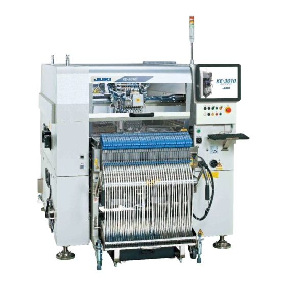
High-Speed Chip Shooter
KE-3010
High-Speed Flexible Mounter
KE-3020V/3020VR
MAINTENANCE GUIDE
JUKI CORPORATION
CUSTOMER SUPPORT DEPARTMENT
ELECTRONIC ASSEMBLY SYSTEMS BUSINESS UNIT
Table of
Contents
Previous
Page
Next
Page
1
2
3
4
5
Advertisement
Table of Contents
Need help?
Do you have a question about the KE-3010 and is the answer not in the manual?
Ask a question
Questions and answers
Subscribe to Our Youtube Channel
Related Manuals for JUKI KE-3010
Industrial Equipment JUKI KE-750 Setup Manual
(59 pages)
Industrial Equipment JUKI KE-760 Setup Manual
(59 pages)
Industrial Equipment JUKI KE-2070 Operation Manual
High-speed chip shooter, high-speed flexible mounter (43 pages)
Industrial Equipment JUKI KE-1070 Maintenance Manual
High-speed chip scooter (100 pages)
Industrial Equipment JUKI KE-2070 Manual
High-speed flexible mounter ms parameter (30 pages)
Industrial Equipment JUKI KE-3020V Maintenance Manual
High-speed chip shooter, high-speed flexible mounter (414 pages)
Industrial Equipment JUKI KE-2000 Series Installation Manual
(52 pages)
Industrial Equipment JUKI KE-2010 Installation Manual
(52 pages)
Industrial Equipment JUKI KE-2020 Installation Manual
(52 pages)
Industrial Equipment JUKI KE-2050 Maintenance Manual
High speed modular mounter (290 pages)
Industrial Equipment JUKI KE-2060 Maintenance Manual
High speed modular mounter (290 pages)
Industrial Equipment JUKI KE-2060R Maintenance Manual
High speed modular mounter (290 pages)
Industrial Equipment JUKI KE-1080 Maintenance Manual
High-speed chip scooter (100 pages)
Industrial Equipment JUKI KE-2080M Manual
High-speed flexible mounter ms parameter (30 pages)
Industrial Equipment JUKI FX-3R Maintenance Manual
High-speed modular mounter (251 pages)
Industrial Equipment JUKI AMS-221F Instruction Manual
Pneumatic type cassette chuck device (17 pages)
This manual is also suitable for:
Ke-3020v
Ke-3020vr
Table of Contents
Save PDF
Print
Rename the bookmark
Delete bookmark?
Delete from my manuals?
Login
Sign In
OR
Sign in with Facebook
Sign in with Google
Upload manual
Upload from disk
Upload from URL


Need help?
Do you have a question about the KE-3010 and is the answer not in the manual?
Questions and answers