Sign In
Upload
Download
Table of Contents
Contents
Add to my manuals
Delete from my manuals
Share
URL of this page:
HTML Link:
Bookmark this page
Add
Manual will be automatically added to "My Manuals"
Print this page
×
Bookmark added
×
Added to my manuals
Manuals
Brands
JUKI Manuals
Industrial Equipment
KE-2070
Manual
JUKI KE-2070 Manual
High-speed flexible mounter ms parameter
Hide thumbs
Also See for KE-2070
:
Operation manual
(43 pages)
,
Maintenance manual
(100 pages)
1
2
3
Table Of Contents
4
5
6
7
8
9
10
11
12
13
14
15
16
17
18
19
20
21
22
23
24
25
26
27
28
29
30
page
of
30
Go
/
30
Contents
Table of Contents
Bookmarks
Table of Contents
Table of Contents
Overview
Definition
Starting up and Exiting the MS Parameter
Configuration
MS Parameter Storage Locations
Basic Operation
Control Menu
Start up
XY Move
Z Move
Conveyor Control
Light Map
Light Setting
Nozzle up Cylinder
Square Adjustment
Origin Rough Adjustment
XY Axis Correction Coefficient
Advertisement
Quick Links
1
Table of Contents
2
Overview
3
Definition
4
Configuration
5
Ms Parameter Storage Locations
6
Basic Operation
7
Nozzle up Cylinder
8
Origin Rough Adjustment
Download this manual
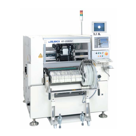
High-Speed Flexible Mounter
KE-2070/KE-2080
MS PARAMETER
JUKI CORPORATION
SMT CENTER CUSTOMER SERVICE DEPT.
ELECTRONIC ASSEMBLY & TEST SYSTEMS DIV.
Table of
Contents
Previous
Page
Next
Page
1
2
3
4
5
Advertisement
Table of Contents
Need help?
Do you have a question about the KE-2070 and is the answer not in the manual?
Ask a question
Questions and answers
Related Manuals for JUKI KE-2070
Industrial Equipment JUKI KE-1070 Maintenance Manual
High-speed chip scooter (100 pages)
Industrial Equipment JUKI KE-2070 Operation Manual
High-speed chip shooter, high-speed flexible mounter (43 pages)
Industrial Equipment JUKI KE-750 Setup Manual
(59 pages)
Industrial Equipment JUKI KE-760 Setup Manual
(59 pages)
Industrial Equipment JUKI KE-3010 Maintenance Manual
High-speed chip shooter, high-speed flexible mounter (414 pages)
Industrial Equipment JUKI KE-3020V Maintenance Manual
High-speed chip shooter, high-speed flexible mounter (414 pages)
Industrial Equipment JUKI KE-2000 Series Installation Manual
(52 pages)
Industrial Equipment JUKI KE-2010 Installation Manual
(52 pages)
Industrial Equipment JUKI KE-2020 Installation Manual
(52 pages)
Industrial Equipment JUKI KE-2050 Maintenance Manual
High speed modular mounter (290 pages)
Industrial Equipment JUKI KE-2060 Maintenance Manual
High speed modular mounter (290 pages)
Industrial Equipment JUKI KE-2060R Maintenance Manual
High speed modular mounter (290 pages)
Industrial Equipment JUKI KE-1080 Maintenance Manual
High-speed chip scooter (100 pages)
Industrial Equipment JUKI KE-2080M Manual
High-speed flexible mounter ms parameter (30 pages)
Industrial Equipment JUKI TR6SNR Maintenance Manual
Matrix tray changer (126 pages)
Industrial Equipment JUKI JX-100 Operation Manual
Flexible compact mounter (41 pages)
This manual is also suitable for:
Ke-2080
Ke-2080m
Table of Contents
Print
Rename the bookmark
Delete bookmark?
Delete from my manuals?
Login
Sign In
OR
Sign in with Facebook
Sign in with Google
Upload manual
Upload from disk
Upload from URL


Need help?
Do you have a question about the KE-2070 and is the answer not in the manual?
Questions and answers