
Related Manuals for JUKI FX-3R


Summary of Contents for JUKI FX-3R
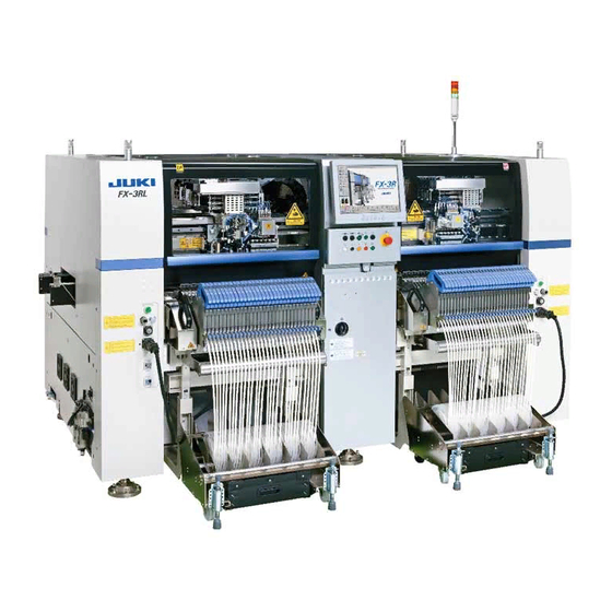
- Page 1 High-Speed Modular Mounter FX-3R MAINTENANCE GUIDE JUKI CORPORATION CUSTOMER SUPPORT DEPARTMENT ELECTRONIC ASSEMBLY SYSTEMS BUSINESS UNIT...
- Page 2 This manual is prepared with extreme care. However, if you have any question or find any error or omission in writing, contact our dealer or JUKI Corporation. JUKI Corporation shall disclaim all the responsibility for any trouble resulting from the user's abnormal operation regardless of Item (3).
-
Page 3: Table Of Contents
FX-3R Maintenance Guide X-Y UNIT....................1-1 1-1. Replacing the Magnescale ..................1-1 1-1-1. X-Axis Magnescale Affixing Position..................1-2 1-1-2. Y-Axis Magnescale Affixing Position..................1-3 1-1-3. Clearance of the Magnescale ....................1-4 1-1-4. Re-obtaining the Parameters after Replacement of the Magnescale........1-4 1-2. - Page 4 FX-3R Maintenance Guide 3-4-1. Replacing the HMS Head ....................3-9 3-4-2. Replacing the Amplifier ......................3-9 3-4-3. Sticking the Label....................... 3-10 3-4-4. Adjusting the HMS Height ....................3-10 3-5. Replacing the Head Board ...................3-11 3-5-1. Replacing the Head Main Board ..................3-11 3-6.
- Page 5 FX-3R Maintenance Guide 5-12. Replacing the Support Table ENC................5-17 5-13. Replacing the Backup Stopper (for EN Type Only) ..........5-18 5-14. Auto PWB Width Adjustment ................5-21 5-14-1. Replacing the AWC Motor....................5-21 5-14-2. Replacing the AWC Origin Sensor..................5-22 5-14-3. Replacing the Transport Stopper Interference Sensor............5-22 5-15.
- Page 6 12-2-2. Setting Up the BIOS......................12-6 12-2-3. Setting Up the Network (This setup is required when communicating with the IS.) ..12-11 12-2-4. Installing the FX-3R System Programs and Flexline DB ..........12-21 12-2-5. Upgrading the FX-3R System Version ................12-32 12-3.
- Page 7 FX-3R Maintenance Guide 13-4-2. CPU Board (40107372) ....................13-17 13-4-3. Position Board (40044540) ....................13-18 13-4-4. cPCI-8994 Board (40048003) ..................13-19 13-4-5. ETHER-MAIN Board (40048066)..................13-20 13-4-6. IP-X5 Board Assembly (40047528).................. 13-21 13-4-7. MOUSE/KEYBOARD Selector (40003281)..............13-22 13-4-8. SUPERIMPOSE Board (40048082)................. 13-24 13-4-9.
- Page 8 FX-3R Maintenance Guide 15-3. Replacing the Movable Cutter Blade (Bottom Blade) of the Tape Cutter....15-10 15-4. Replacing the Fixed Cutter Blade (Upper Blade) of the Tape Cutter ....15-12 15-5. Grease up......................15-13 [16] FX-3R JIG LISTS ..................16-1 Rev. 1.00...
-
Page 9: X-Y Unit
FX-3R Maintenance Guide To prevent any trouble caused by accidental machine start, always shut-down the power before starting the maintenance and adjustment work. The XY-axis uses a very strong magnet. • Do not put any metallic object close to the magnet surface. Once the... -
Page 10: X-Axis Magnescale Affixing Position
FX-3R Maintenance Guide 1-1-1. X-Axis Magnescale Affixing Position (1) Affix the magnescale while guiding it using the X_MSC install jig. The affixing starting line for the LF/RF is indicated by the mark-off line on the left side when viewed from the front and that for the LR/RR is indicated by the mark-off line on the left when viewed from the rear. -
Page 11: Y-Axis Magnescale Affixing Position
FX-3R Maintenance Guide 1-1-2. Y-Axis Magnescale Affixing Position (1) Affix the magnescale while aligning the center portion with the top surface of the Y-frame C and its side surface with the rail side surface of the Y-frame S. Specification value: Magnescale affixing position (Displacement in the direction parallel with the head movement) ±... -
Page 12: Clearance Of The Magnescale
FX-3R Maintenance Guide 1-1-3. Clearance of the Magnescale (1) Loosen the screws fixing the sensor and put the clearance jig with a thickness of 0.25 mm in the clearance between the magnescale and sensor head. (2) Tighten the set screws of the sensor head to remove the clearance jig with a thickness of 0.25±0.1 mm. -
Page 13: Replacing The Limit Sensor And Origin Near Sensor
FX-3R Maintenance Guide 1-2. Replacing the Limit Sensor and Origin Near Sensor (1) When replacing only the sensor, it is not necessary to adjust the position. (2) When replacing the sensor together with the bracket, it is necessary to adjust the position. -
Page 14: Replacing The Y +Limit Sensor And Yb-Near Sensor
FX-3R Maintenance Guide 1-2-2. Replacing the Y +Limit Sensor and YB-Near Sensor (1) When the distance between each rubber stopper and the Y linear base becomes 5 mm, make the adjustment so that each limit sensor is turned ON, and then secure each limit sensor with the screws. -
Page 15: Replacing The X-Axis Interference Sensor (Y-C Sensor)
FX-3R Maintenance Guide 1-2-3. Replacing the X-axis Interference Sensor (Y-C Sensor) (1) When the distance between each rubber stopper and the Y linear base becomes 5 mm, make the adjustment so that each limit sensor is turned ON, and then secure each limit sensor with the screws. -
Page 16: Replacing The Cable Bear
FX-3R Maintenance Guide 1-3. Replacing the Cable Bear 1-3-1. Replacing the X-Axis Cable Bear (1) Remove the screws and hexagon nuts fixing the X-cable bear. (2) Open the flap of the X-cable bear, disconnect the cables, and replace the cable bear. -
Page 17: Replacing The Y-Axis Cable Bear
FX-3R Maintenance Guide 1-3-2. Replacing the Y-Axis Cable Bear (1) Remove the screws and hexagon nuts fixing the Y-cable bear. (2) Open the flap of the Y-cable bear, disconnect the cables, and replace the cable bear. (3) Apply the grease evenly to four surfaces inside the cable bear. -
Page 18: Replacing The Roller Lubrication Part
FX-3R Maintenance Guide 1-4. Replacing the Roller Lubrication Part (1) Remove the screws that secure the lubrication unit. Lubrication unit Fixing screw Scraper (2) Insert a precision screwdriver (−) into the portion indicated by an arrow shown in the Fig. on the right to detach the lubrication part from the bracket. -
Page 19: Head Unit
FX-3R Maintenance Guide To prevent any trouble caused by accidental machine start, always shut-down the power before starting the maintenance and adjustment work. The XY-axis uses a very strong magnet. • Do not put any metallic object close to the magnet surface. Once the... - Page 20 FX-3R Maintenance Guide 17) Assemble the head main stay. First, push the head main stay against the bottom of the head main base and assemble them. After that, adjust the height levels of the stay stands L・R and Z-power connector base, and then assemble them.
- Page 21 FX-3R Maintenance Guide SL4042591SC × 4 pcs. Head cable guide Wind direction Head fan Fan guard SL6041492TN × 4 pcs. SL6040892TN × 2 pcs. Upper side: SL6040892TN × 5 pcs. Head core base Head main stay Stay stand R (Opposite side: L) SL6041092TN ×...
- Page 22 FX-3R Maintenance Guide ZT-driver board Right side (Same as the left side) ZT-driver support SL6041492TN × 6 pcs. (one side) SL6040892TN × 4 pcs. Z-motor power cable Z-power connector base Rev. 1.00...
- Page 23 FX-3R Maintenance Guide Solenoid valve SV support A Head cover SL6030692TN × 2 pcs. SL6030692TN × 4 pcs. XM base Head unit SL6052092TN × 6 pcs. Rev. 1.00...
- Page 24 FX-3R Maintenance Guide [Connection destinations of θ-motor cable connectors to be connected to ZT-driver PCB] ∗ Each connector is described by relevant head No. ∗ Connect the θ-motor power cables and θ-motor encoder cables while referring to the Figure below.
-
Page 25: Replacing The Motor
FX-3R Maintenance Guide 2-2. Replacing the Motor 2-2-1. Replacing the Z-Motor After the Z motor has been replaced, it is absolutely necessary to re-input the MS parameters related to the Z-axis home position adjustment, Z-axis height, and laser. (For details of input items, see section 2-7.) - Page 26 FX-3R Maintenance Guide After the Z-axis motor has been assembled, obtain the PWB top surface height of the MS parameter. If this value does not fall between −2 and +2mm, readjust the positional relationship of the Z-motor axis and the ball screw, obtain the MS parameter again, and check to make sure that the PWB top surface height falls between −2 and +2mm.
-
Page 27: Replacing The Θ-Motor
FX-3R Maintenance Guide 2-2-2. Replacing the θ-Motor After the θ-motor has been replaced, it is absolutely necessary to re-input the MS parameters related to the axis home. (For details of input items, see section 2-7.) Disconnect the motor cables from the 40044533 servo amplifier board. -
Page 28: Replacing The Laser Sensor (Lnc60)
FX-3R Maintenance Guide 2-3. Replacing the Laser Sensor (LNC60) After the LNC60 has been replaced, it is absolutely necessary to re-input the MS parameters related to the laser. (See section 2-7.) Disconnect the connectors (encoder and SL6041692TN IEEE1394) and remove the mounting screws SEMS cap bolt with (3 pcs.) to detach the LNC60. -
Page 29: Replacing The Head Up Cylinder
FX-3R Maintenance Guide 2-4. Replacing the Head Up Cylinder Turn the finger valve to stop the air supply 40046524 and disconnect the air tubes. Air cylinder Remove the head up springs from both ends, and then remove the nut from the... -
Page 30: Replacing The Belts
FX-3R Maintenance Guide 2-5. Replacing the Belts 2-5-1. Replacing the Timing Belt Z After the timing belt Z has been replaced, it is absolutely necessary to re-input the MS parameters related to the Z-axis home position adjustment, Z-axis height, and laser. (For details of input items, see section 2-7.) -
Page 31: Replacing The Z-Slide Shaft
FX-3R Maintenance Guide 2-6. Replacing the Z-Slide Shaft When the Z-slide shaft has been replaced, it is necessary to input the MS parameters related to the θ-axis and Z-axis home position adjustment, Z-axis height, and laser again. (For details about input items, see section 2-7.) (1) Remove the hollow set screw (×1) from the lower portion of the coupling. -
Page 32: Readjustment After Replacement Of Head Unit
FX-3R Maintenance Guide 2-7. Readjustment After Replacement of Head Unit Table 2-7-1 List of Readjustment Items After Replacement of Head Unit Laser ID No. Component speed Mounting general Laser offset Head offset setup measurement offset Head unit assembly Z-motor θ-motor... -
Page 33: Parts Around The Head
FX-3R Maintenance Guide To prevent any trouble caused by accidental machine start, always shut-down the power before starting the maintenance and adjustment work. The XY-axis uses a very strong magnet. • Do not put any metallic object close to the magnet surface. Once the... - Page 34 FX-3R Maintenance Guide Tightening torque: 0.15±0.02 N⋅m 40046835 Round head screw (×2) 40068170 Solenoid valve Solenoid valve B 40068169 Solenoid valve V SV cover Cable guide SL6030692TN SL6030692TN SL6030692TN SEMS cap bolt with washer SEMS cap bolt with washer SEMS cap bolt with washer M3×6...
-
Page 35: Replacing The Filter
FX-3R Maintenance Guide 3-2. Replacing the Filter Before replacing the filter, always shut-down the main compressed air. <Replacing the head filter> Remove the cap bolts (×2) and cap bolts (×2) to detach the filter box U. (O-ring is mounted under the filter box U. Carefully handle this O-ring so that it is not lost.) Take out the filter and replace it with a new one. -
Page 36: Replacing The Bad Mark Sensor
FX-3R Maintenance Guide 3-3. Replacing the Bad Mark Sensor 3-3-1. Sensor Assembly Remove the SEMS cap bolts (×2) to detach the BMR lens bracket A (B). (The following Figure shows the BM lens bracket A (for RR head).) Remove the nut... -
Page 37: Adjusting The Sensor Height
FX-3R Maintenance Guide 3-3-2. Adjusting the Sensor Height Move the bad mark sensor to a point above the calibration block. Loosen the SEMS cap bolts at two places and move SEMS cap the BMR lens bracket so that the distance between the bolt M3×6... -
Page 38: Assembling The Fiber Unit To The Amplifier
FX-3R Maintenance Guide 3-3-4. Assembling the Fiber Unit to the Amplifier Open the case cover and flip down the one-touch lock lever. Make the projection faced toward the side where there is no LED and insert the fiber into the amplifier approx. -
Page 39: Amplifier Setting
FX-3R Maintenance Guide 3-3-5. Amplifier Setting Use as it is the amplifier in the factory-settings. Turn on the power supply to make sure that the status shown in the following figure is provided. L = Light ON operation T = Teaching mode... -
Page 40: Manual Setting Method For The F70R Fiber Sensor Amplifier
FX-3R Maintenance Guide 3-3-6. Manual Setting Method for the F70R Fiber Sensor Amplifier The amplifier setting method is different from the factory-set status. Set this amplifier manually. - Setting the operation mode Operation mode Sensor function Mode switch - Selecting the sensor function (teaching mode setting method) Switch the sensor mode switch from [RUN] to [SELECT]. -
Page 41: Replacing The Hms
FX-3R Maintenance Guide 3-4. Replacing the HMS 3-4-1. Replacing the HMS Head Remove the cap bolts (×2) to detach the HMS head. (The following Figure shows the HMS head for the LF and RR heads.) Reassemble the parts and components in the reverse order of disassembly. In the same manner as described above, detach the HMS head from the LR and RF heads. -
Page 42: Sticking The Label
FX-3R Maintenance Guide 3-4-3. Sticking the Label After the label sticking surface has been degreased, stick the label. (The following Figure shows the LF and RR heads.) The LR and RF heads have the cable running direction opposite to that of the LF and RR heads. -
Page 43: Replacing The Head Board
FX-3R Maintenance Guide 3-5. Replacing the Head Board 3-5-1. Replacing the Head Main Board Remove the round screws (×6) and clamps (×2) to detach the main cover. Disconnect various connectors and remove the SEMS cap bolts (×6) to detach the head main board. -
Page 44: Replacing The Zt-Driver Board
FX-3R Maintenance Guide 3-6. Replacing the ZT-Driver Board 3-6-1. Replacing the ZT-Driver Board Refer to section 2-1, “Replacing the Head Unit”, and steps 1) to 6), 14), and 16) in “Adjustment after replacement” of Chapter 2. Remove the SEMS cap bolts (×8) from the ZT-driver support to detach the ZT-driver board. -
Page 45: Occ Assembly
FX-3R Maintenance Guide To prevent any trouble caused by accidental machine start, always DANGER shut-down the power before starting the maintenance and adjustment work. OCC ASSEMBLY 4-1. Replacing the OCC Assembly Remove the SEMS cap bolts to detach the lens assembly. -
Page 46: Replacing The Ccd Camera And Lens
FX-3R Maintenance Guide 4-2. Replacing the CCD Camera and Lens Detach the lens assembly from the XM base A (B) using the procedure described in section 4-1, Replacing the OCC Assembly. Remove the SEMS cap bolts (×2) and SEMS cap bolts (×2) securing the CCD camera and... -
Page 47: Replacing The Occ Coaxial/Angle Light Board Assemblies
FX-3R Maintenance Guide 4-3. Replacing the OCC Coaxial/Angle Light Board Assemblies Detach the light assembly from the XM base using the procedure described in section 4-1, Replacing the OCC Assembly. Remove the round head screws (×2) to replace the OCC coaxial light board assembly. -
Page 48: Replacing The Lens Filter
FX-3R Maintenance Guide 4-4. Replacing the Lens Filter Detach the light assembly from the XM base using the procedure described in "Replacing the OCC Assembly". Remove the SEMS cap bolt (×1), collar (×1) and shoulder screws (×2) to detach the light filter U support, lens filter and guide plate. - Page 49 FX-3R Maintenance Guide ∗ Adjusting the polarizing filter Put a white ceramic board on the calibration block and move the camera above the board. Loosen the setscrew. Turn the light filter U support and secure it when the screen is at the brightest level.
-
Page 50: Adjusting The Focus
FX-3R Maintenance Guide 4-5. Adjusting the Focus <Procedure> 1) Mount the OCC focus adjustment jig on the calibration block. 2) Move the OCC camera to a position above the OCC focus adjustment jig. (Manual movement) 3) Turn on the light with the standard light selected and start up [MS parameters]-[Check Adjustment]-[OCC Focus Adjustment]. -
Page 51: Adjusting The Occ Light Quantity
FX-3R Maintenance Guide OCC focus adjustment jig Line drawing direction 40069017 Set the light value to a level, at which the OCC focus adjustment jig vertical lines of the focus adjustment jig can be seen, to adjust the light quantity. -
Page 52: Replacing The Solder Recognition Light Board
FX-3R Maintenance Guide 4-7. Replacing the Solder Recognition Light Board <Procedure> 1) Remove the brazier head screws to detach the PRISM BASE, OCC angle light board, and board spacers. 2) Reassemble the components in the reverse order of disassembly. 3) After the solder recognition light has been replaced, adjust the OCC light. (See 4-8, List of Readjustment Items after Replacement.) -
Page 53: Readjustment After Replacement Of Occ Unit
FX-3R Maintenance Guide 4-8. Readjustment After Replacement of OCC Unit : Mandatory : Check −: Unnecessary ∗: Optional Table 4-8-1 List of Readjustment Items after Replacement OCC lens OCC light Light board Lens filter assembly assembly assembly OCC focus adjustment ―... -
Page 54: Board Transport Unit
FX-3R Maintenance Guide To prevent any trouble caused by accidental machine start, always DANGER shut-down the power before starting the maintenance and adjustment work. BOARD TRANSPORT UNIT 5-1. Replacing the Transport Belt Loosen the transport belt tension adjustment pulley. (Locations indicated by arrows in the... -
Page 55: Replacing The Transport Pulley
FX-3R Maintenance Guide 5-2. Replacing the Transport Pulley Two kinds of transport pulleys are available. If the mounting position is changed or the pulley is mounted incorrectly, this may cause incorrect pulley rotation or incorrect alignment of the transport belt, resulting in wear on the belt. -
Page 56: Replacing The Station, In, Out, And Joint Motors
FX-3R Maintenance Guide 5-3. Replacing the STATION, IN, OUT, and JOINT Motors Disconnect the connector of the motor relay cable. Loosen the screws fixing the motor bracket to detach the drive belt from the motor pulley Loosen the motor fixing screws and detach the motor Reassemble the parts and components in the reverse order of disassembly. -
Page 57: Replacing The In And Out Sensors
FX-3R Maintenance Guide 5-4. Replacing the IN and OUT Sensors Bind the cables A and B with binding bands, taking care that they are not pulled or loosened excessively during adjustment of sensor position. Left-side sensor Right-side sensor Figure 5-4-1 IN and OUT Sensors <Adjusting the sensitivity>... -
Page 58: Replacing The Wait, Stop, And C-Out Sensors
FX-3R Maintenance Guide 5-5. Replacing the WAIT, STOP, and C-OUT Sensors Sensor emitting area Sensor receiving area L-STATION R-STATION WAIT-R WAIT-L STOP-R STOP-L Amplifier COUT-R COUT-L WAIT-L WAIT-R STOP-R COUT-R STOP-L COUT-L Figure 5-5-1 Placement of Sensors (Left → Right Transport) 5-5-1. - Page 59 FX-3R Maintenance Guide [List of Replacement Parts] Table 5-5-2-1 WAIT/STOP/C-OUT Sensors Part No. Part name Remarks L specification 40047772 WAIT-L SENSOR ASM For transport unit L 40047774 STOP-L SENSOR ASM Fiber unit is an 40047773 COUT-L SENSOR ASM accessory of the...
-
Page 60: Adjusting The Sensitivity Of The Wait/Stop/C-Out Sensor
FX-3R Maintenance Guide 5-5-3. Adjusting the Sensitivity of the WAIT/STOP/C-OUT Sensor L specification <Changing the output> The output change-over setting is changed from LO (output is turned ON when the light is received) to DO (output is turned ON when the light is interrupted). - Page 61 FX-3R Maintenance Guide XL specification Main digital display (Red) RUN indicator 2 CH Sub-digital display (Green) RUN indicator 1 CH (Orange) (Orange) Operation key Lock lever SET/RUN change-over switch Channel change-over switch Figure 5-5-3-5 Sensor Amplifier with XL Specification <Setting procedure>...
- Page 62 FX-3R Maintenance Guide <Power tuning procedure> Change the SET/RUN change-over switch to the “RUN” Change to the RUN mode. mode. Figure 5-5-3-13 RUN Mode Set the auto width to “610 mm”. Keep the square button of the operation key pressed for 3 sec.
-
Page 63: Replacing The Stopper Cylinder
FX-3R Maintenance Guide 5-6. Replacing the Stopper Cylinder Remove the hexagon nut . The parts , and can then be removed. Remove the hexagon nut securing the cylinder. (Tool: Single-ended wrench, 11-size) Detach the speed controller from the cylinder. (At this time, check what side the speed controller has been mounted.) -
Page 64: Replacing The Support Table Home Position Sensor (Bu Home Position Sensor)
FX-3R Maintenance Guide 5-7. Replacing the Support Table Home Position Sensor (BU Home Position Sensor) Detach the sensor from the sensor bracket. Adjust the distance between the sensor and sensor dog to 1 mm. For tie-band 40046962 BU sensor bracket... -
Page 65: Replacing The Pusher Y Cylinder (Outer Shape Reference)
FX-3R Maintenance Guide 5-9. Replacing the Pusher Y Cylinder (Outer Shape Reference) Remove the parts to detach the cylinder. As the cylinder is detached, the spring is also then removed. Detach the speed controller from the cylinder. (At this time, check what side the speed controller has been mounted.) -
Page 66: Replacing The Centering Pin (Optional)
FX-3R Maintenance Guide 5-10. Replacing the Centering Pin (Optional) Loosen the screws of the guide block A and guide block B to detach the centering pin together with the guide blocks. At this time, also detach the T-PIN sensor (together with its bracket) from the reference side. -
Page 67: Replacing The Support Table Motor (Bu Motor)
FX-3R Maintenance Guide 5-11. Replacing the Support Table Motor (BU Motor) Remove the support table as described below. 1. Stretch the transport width as much as possible. 2. Remove 12 (∗) pan head screws from the support table to detach the table. -
Page 68: Adjusting The Gap Between Torque Supporter And Support Motor
FX-3R Maintenance Guide 5-11-1. Adjusting the Gap between Torque Supporter and Support Motor The gap between the torque supporter and support table motor must be adjusted to 1.1 mm. Figure 5-11-1-1 Motor and Torque Supporter 5-11-2. Adjusting the Tension of the Support Table Driving Timing Belt... - Page 69 FX-3R Maintenance Guide <Adjustment Procedure> Select [Manual Control] → [Transport Control] to set the support table to a position of −27mm. Based on the lowest point of four measured points, turn the adjustment screw in the down direction (screw tightening direction) to make the adjustment so that the difference among four measured points is 0.02mm or less.
-
Page 70: Replacing The Support Table Enc
FX-3R Maintenance Guide 5-12. Replacing the Support Table ENC Detach the support table in the same manner as described in 5-11, Replacing the support table Motor. Loosen the screw , and move the tension support assembly in the arrow direction to... -
Page 71: Replacing The Backup Stopper (For En Type Only)
FX-3R Maintenance Guide 5-13. Replacing the Backup Stopper (for EN Type Only) Loosen the BU stopper bracket set screw with the air turned ON to adjust the crosswise position of the BU stopper. Loosen the air cylinder set screw and make the adjustment so... - Page 72 FX-3R Maintenance Guide For details about how to replace the parts and connect the cables and piping inside the solenoid valve assembly, see Figure 5-13-2. [For transport unit L] [For transport unit R] Figure 5-13-2 Solenoid Valve Assembly L Specification 43mm...
- Page 73 FX-3R Maintenance Guide [List of Replacement Parts] Table 5-13-2 Reference for PWB Positioning Hole Part No. Part name Part No. Part name 1∗ PV150209000 5-PORT SOLENOID VALVE 7∗ PV150209000 5-PORT SOLENOID VALVE PV150209300 5-PORT SOLENOID VALVE PV150209300 5-PORT SOLENOID VALVE...
-
Page 74: Auto Pwb Width Adjustment
FX-3R Maintenance Guide 5-14. Auto PWB Width Adjustment 5-14-1. Replacing the AWC Motor Disconnect the connectors of the motor relay cable. Loosen the set screws on the motor bracket to detach the drive belt from the motor pulley Loosen the motor set screws... -
Page 75: Replacing The Awc Origin Sensor
FX-3R Maintenance Guide 5-14-2. Replacing the AWC Origin Sensor Loosen the screw . Detach the AWC origin sensor from the AWC origin sensor bracket replace it with a new one. Assemble the AWC origin sensor so that the clearance between the AWC sensor dog the AWC origin sensor becomes 1 mm. -
Page 76: Replacing The Barcode Reader (On-Demand Production, Option For Scs)
FX-3R Maintenance Guide 5-15. Replacing the Barcode Reader (On-Demand Production, Option for SCS) (1) Functions The barcode reader of the transport unit reads the 1D-barcode of the PWB and transmits the results to the cPCI-8994 PCB through the RS232C. (2) Meaning of LED... - Page 77 FX-3R Maintenance Guide (3) Replacement procedure The barcode reader (HX006100000) has been assembled to the PWB transport inlet as shown in the Figure below. (This Figure shows the left → right transport machine. For the right → left transport machine, the barcode reader is assembled to a position opposite to that shown in this Figure.)
- Page 78 FX-3R Maintenance Guide 3) Disconnect the BARCODE READER relay connector. (The relay connector is connected to the relay cable at a position close to that shown in the Figure below.) The black line shows the cable route for the left → right transport while the blue line shows that for the right →...
-
Page 79: Cal Block
FX-3R Maintenance Guide To prevent any trouble caused by accidental machine start, always DANGER shut-down the power before starting the maintenance and adjustment work. CAL BLOCK 6-1. Replacing the CAL Board Assembly (1) Disconnect the cables from the CAL board. -
Page 80: Atc
FX-3R Maintenance Guide To prevent any trouble caused by accidental machine start, always DANGER shut-down the power before starting the maintenance and adjustment work. After the ATC base has been replaced, it is necessary to obtain “ATC Offset” of the MS parameters again. -
Page 81: Replacing The Atc Open And Close Sensors
FX-3R Maintenance Guide Adjust the sensor dog position When opened: Open the slide plate and secure the dog at a position where the dog is further moved 1mm after the LED goes off. When closed: Close the plate. The plate must be stopped at a position where it is further moved 1mm after the LED is lit. -
Page 82: Adjusting The Speed Controller
FX-3R Maintenance Guide 7-3. Adjusting the Speed Controller Rotate the knob of the speed controller to adjust the opening/closing time of the slide plate to the standard adjustment value. (As a guide, rotate the knob about two and a half turns from the fully closed position.) After adjustment, fix the knob. -
Page 83: Feeder Bank, Replacement Table And Electric Bank (Optional)
FX-3R Maintenance Guide To prevent any trouble caused by accidental machine start, always DANGER shut-down the power before starting the maintenance and adjustment work. FEEDER BANK, REPLACEMENT TABLE AND ELECTRIC BANK (OPTIONAL) 8-1. Common Parts and Units for Mechanical Feeder and Electric Feeder 8-1-1. -
Page 84: Adjusting The Speed Controller Of The Bank-Up Cylinder (Optional Replacement Table)
FX-3R Maintenance Guide 8-1-2. Adjusting the Speed Controller of the Bank-Up Cylinder (Optional Replacement Table) For the speed controllers of the right side cylinder, adjust those of the fixed and left side cylinders. The speed controllers have been set so that... -
Page 85: Replacing The Selector Switch (Optional Replacement Table)
FX-3R Maintenance Guide 8-1-4. Replacing the Selector Switch (Optional Replacement Table) Shut-down the main compressed air to the main unit (with the hand valve). Turn the selector switch cap counterclockwise to detach the selector switch from the cover. Mount the half-union and silencer on a new selector switch and secure the selector switch to the cover with the cap. -
Page 86: Replacing The Cables And Connectors Of Replacement Table (For Intelli Trolley)
FX-3R Maintenance Guide 8-1-6. Replacing the Cables and Connectors of Replacement Table (For Intelli trolley) Replacing the connector (HK065120060) Before replacing the connector, disconnect the cable connected to both ends of the connector. Connector HK065120060 Portion A Figure 8-1-6-1 Replacement Table when Viewed from Mounter... - Page 87 FX-3R Maintenance Guide Replacing the cable (RFID JOINT CABLE ASM: 40079659) Before replacing the cable, disconnect the cable connection from the antenna and relay connector. Disconnect the cable from the cable securing materials (cable band and cable clamp). After the cable has been replaced, secure the cable and connect it to the connector in the original manner.
-
Page 88: Replacing The Antenna Of The Replacement Table (For Intelli Trolley)
FX-3R Maintenance Guide 8-1-7. Replacing the Antenna of the Replacement Table (For Intelli trolley) Disconnect the cable from the connector of the antenna array. Antenna array 40073664 RFID JOINT CABLE ASM 40079659 Figure 8-1-7-1 Replacement Table when Viewed from the Front (Feeder Insertion Side) Remove the screws (6 pcs.) securing the antenna array. - Page 89 FX-3R Maintenance Guide When mounting the antenna array, mount it so that the positional relationship is as follows. Note that it is not allowed to reuse the conductive tape (HX002680000). Antenna array 40073664 Tightening direction Conductive tape HX002680000 Shield bracket 60...
-
Page 90: Bank And Replacement Table For Mechanical Feeder
FX-3R Maintenance Guide 8-2. Bank and Replacement Table for Mechanical Feeder 8-2-1. Overall Drawing 40047264 Bank lifter RS 40047265 Bank lifter LS 40063859 Drive cylinder E2708729000 Driver bracket (30) 40047249 Drive bracket Figure 8-2-1-1 Overall Drawing Rev. 1.00... -
Page 91: 8-2.2. Replacing The Drive Cylinder
FX-3R Maintenance Guide 8-2.2. Replacing the Drive Cylinder Turn OFF the power to the main unit completely before starting the replacement work. Shut-down the main pressure air to the main unit (with the hand valve). If the machine is equipped with an optional replacement table, disconnect the air tube and move the replacement table outside the main unit. -
Page 92: Adjusting The Speed Controller Of The Drive Cylinder
FX-3R Maintenance Guide 8-2-3. Adjusting the Speed Controller of the Drive Cylinder The following describes how to adjust the up speed of the drive cylinder. Detach the drive cylinders to be adjusted from the driver bracket. Connect the air tube and connector. -
Page 93: Replacing The Bank Pcb
FX-3R Maintenance Guide 8-2-5. Replacing the Bank PCB Remove the mounting screws to detach the front panel. Disconnect the connectors (cables) from the mechanical bank PCB. Remove the round head screws (8 pcs.) to detach the mechanical bank PCB and replace it with a new one. -
Page 94: Replacement Table For Electric Feeder
FX-3R Maintenance Guide 8-3. Replacement Table for Electric Feeder To prevent any trouble caused by accidental machine start, always DANGER shut-down the power before starting the maintenance and adjustment work. 8-3-1. Overall Drawing (Replacement Table for ETF) 40084666 40084911 E_Trolley cover R... - Page 95 FX-3R Maintenance Guide 40084914 Bank PCB box assembly Figure 8-3-1-2 Overall Drawing (From Obliquely downward View Field) 8-13 Rev. 1.00...
-
Page 96: Overall Drawing (Lifter Unit)
FX-3R Maintenance Guide 8-3-2. Overall Drawing (Lifter Unit) 40063873 Lifter LL assembly 40063872 Lifter LR assembly PA630850100 Air cylinder PV010505000 Mechanical valve Figure 8-3-2-1 Overall drawing (Lifter Unit) 8-14 Rev. 1.00... -
Page 97: Replacing The Bank Pcb
FX-3R Maintenance Guide 8-3-3. Replacing the Bank PCB Remove the mounting bolts (hexagon socket head cap bolt with washer, M3 L=8) to detach the front panel. Disconnect the connectors (cables) from the electric bank PCB. Remove the PCB mounting screws (round head screw with washer, M3 L=8) to replace the PCB. -
Page 98: Replacing The Connector Cable
FX-3R Maintenance Guide 8-3-4. Replacing the Connector Cable Remove the connector mounting screws to detach the connector from the FDC bracket. Detach the front panel. (See Figure 8-3-3.) Disconnect the connectors from the electric bank PCB and replace the cables. -
Page 99: Replacing The Connector For Off-Line Setup
FX-3R Maintenance Guide 8-3-5. Replacing the Connector for Off-line Setup Disconnect the connector for the off-line setup from the E trolley cover R. Disconnect the connector connecting the cable of the connector for the off-line setup and the relay cable to the electric bank PCB. After that, replace the connector for the off-line setup. -
Page 100: Replacing The Etf Incorrect Insertion Detection Sensor
FX-3R Maintenance Guide 8-3-6. Replacing the ETF Incorrect Insertion Detection Sensor In the FX-3R, the sensors are arranged as shown in the Figure below. To remove the sensor together with the bracket, the sensor height needs to be adjusted. To replace only the sensor, start the work from step 4). - Page 101 FX-3R Maintenance Guide Adjust the height of the sensor you have replaced. Adjust the top surface of the EFDS bracket to a height of 128 ± 0.1 mm from the top surface of the bracket. However, the height difference of the left and right EFDS brackets that become a pair (light receiving and light emitting) must be 0.1 mm or less.
- Page 102 FX-3R Maintenance Guide Adjust the potentiometer. Adjust the potentiometer after the sensor mounting position, mounting position in the Y-direction (sensor is secured to the center of the oval hole in the sensor BR), and optical axis have been adjusted. Potentiometer...
-
Page 103: Electric Fixed Bank (Optional)
FX-3R Maintenance Guide 8-4. Electric Fixed Bank (Optional) To prevent any trouble caused by accidental machine start, always DANGER shut-down the power before starting the maintenance and adjustment work. 8-4-1. Overall Drawing 40095345 Fixed bank unit for ETF 40084841 EF setup cable 1 bracket... - Page 104 FX-3R Maintenance Guide 40095349 Bank PCB box assembly (EO) Figure 8-4-1-2 Overall Drawing (From Obliquely downward View Field) 8-22 Rev. 1.00...
-
Page 105: Replacing The Outer Bank Pcb And Connector Cable
FX-3R Maintenance Guide 8-4-2. Replacing the Outer Bank PCB and Connector Cable The bank PCB and connector cable are replaced in the same manner as described for the replacement table for ETF. To do so, see the sections below. Replacing the bank PCB → 8-3-3 Replacing the connector cable →... -
Page 106: Pneumatic Units
FX-3R Maintenance Guide To prevent any trouble caused by accidental machine start, always DANGER shut-down the power before starting the maintenance and adjustment work. PNEUMATIC UNITS 9-1. Replacing the Digital Pressure Switch (Positive Pressure) Close the hand valve at the lower left portion of the main unit. - Page 107 FX-3R Maintenance Guide <Setting Procedure> [LED] panel [SET] button [ ] button [ ] button Figure 9-1-1-1 Digital Pressure Switch Setting the display mode and hysteresis mode Keep the button pressed for 2 sec. or longer. The display will become .
-
Page 108: Replacing The Filter Element
FX-3R Maintenance Guide 9-2. Replacing the Filter Element Turn the filter element main unit 45( clockwise or counterclockwise to pull it out downward while lowering the slide part. When replacing the filter element B on the air filter side, turn the resin part fixing the filter element B counterclockwise to detach it. -
Page 109: Replacing The Digital Pressure Switch (Negative Pressure)
FX-3R Maintenance Guide 9-3. Replacing the Digital Pressure Switch (Negative Pressure) Make sure that the vacuum pump is not functioning. Remove the screws (2 locations) to open the cover SB_A (open/close cover). Disconnect φ6-air tube and connector from the digital pressure switch. - Page 110 FX-3R Maintenance Guide <Setting Procedure> [LED] panel [SET] button [ ] button [ ] button Figure 9-3-1-1 Digital Pressure Switch Setting the display mode and hysteresis mode Keep the button pressed for 2 sec. or longer. The display will become .
- Page 111 FX-3R Maintenance Guide 9-4. Replacing the Vacuum Pump Parts The reference replacement timing for the consumable parts listed below is one year after starting of the operation. Replace or clean the consumable parts while referring to the procedure below. All parts that need to be replaced are included in the consumable part set (part No.
- Page 112 FX-3R Maintenance Guide Open the cover of the terminal box and disconnect the cables from the terminal block. Figure 9-4-2 Disconnecting the Cables Loosen the hexagon socket head cap bolts (M6 × L16) fixing the handle with an Allen wrench having a width between across flats of 5 mm.
- Page 113 FX-3R Maintenance Guide <Detaching the head cover> Loosen four hexagon socket head cap bolts (M6 × L30) fixing the head cover with an Allen wrench, and then remove the hexagon socket head cap bolts. Figure 9-4-5 Removing the Head Cover Set Screws Detach the head cover.
- Page 114 FX-3R Maintenance Guide <Detaching the support plate, cup packing, and suction valve interference prevention rubber> Put a mark on the support plate with an oil felt pen so that it meets the mark on the casing. Figure 9-4-10 Putting a Mark Loosen four countersunk head screws of the support plate.
- Page 115 FX-3R Maintenance Guide <Detaching/replacing the cylinder detailed parts> Loosen the round head screws (M3 × L5) fixing the exhaust valve support plate. Detach the exhaust valve support plate, exhaust valve backup, and exhaust valve. Figure 9-4-14 Removing the Round Head Screws Loosen the round head screws (M3 ×...
-
Page 116: Switches
FX-3R Maintenance Guide To prevent any trouble caused by accidental machine start, always DANGER shut-down the power before starting the maintenance and adjustment work. [10] SWITCHES 10-1. Replacing the Push-Button Switch Servo free On-line switch Start switch switch Keyboard setting... -
Page 117: Replacing The Emergency Stop Switch
FX-3R Maintenance Guide Detach the switch panels from the front and rear sides. (Front, screws at 2 locations, Inside of cover, screws at 2 locations) Detach the operation board. To detach the switch, remove the root part (mounting nut) of the switch from the back of the cover and pull out the case from the cover surface. -
Page 118: Replacing The Cover Open Switch
FX-3R Maintenance Guide 10-3. Replacing the Cover Open Switch 10-3-1. Switch Main Unit Disconnect the connector of the switch from the relay connector. Cut the tie-up band and remove the set screws (SL6042042TN) to replace the switch main unit. Reassemble the components in the reverse order of disassembly. -
Page 119: Operation Key
FX-3R Maintenance Guide 10-3-2. Operation Key Remove two mounting screws to replace the SAFETY_SWITCH_KEY SAFETY_SWITCH_KEY SL6041042TN SEMS cap bolt with washer M4×10 Figure 10-3-2-1 Operation Key 10-4 Rev. 1.00... -
Page 120: Replacing The Push-Button Switch (Ce Marking Machine)
FX-3R Maintenance Guide 10-4. Replacing the Push-Button Switch (CE Marking Machine) On-line switch Start switch Maintenance key switch Keyboard Origin return Stop Single cycle setting switch switch switch switch Figure 10-4-1 Switch Names on Front Operation Panel Start switch Keyboard... - Page 121 FX-3R Maintenance Guide Detach the switch panels from the front and rear sides. (Front, screws at 2 locations, Inside of cover, screws at 2 locations) Detach the operation board. To detach the switch, remove the root part (mounting nut) of the switch from the back of the cover and pull out the case from the cover surface.
-
Page 122: Replacing And Adjusting The Feeder Float Sensor
[11] REPLACING AND ADJUSTING THE FEEDER FLOAT SENSOR (1) In the FX-3R, the sensors are arranged as shown in the Figure below. If the sensor is detached together with the bracket, it becomes necessary to adjust the sensor height. - Page 123 FX-3R Maintenance Guide Replace the sensor in the detached bracket assembly with a new one. FSD bracket assembly (front left portion) SL4031481SC SEMS cap bolt M3×14 EA9500B0100 Tie-up band FSD bracket 40001312 OCC shim C E2157729000 FSD spacer Sensitivity adjustment side...
- Page 124 FX-3R Maintenance Guide FSD bracket assembly (rear left portion) SL4031481SC SEMS cap bolt M3×14 EA9500B0100 FSD bracket Tie-up band 40001312 OCC shim C E2157729000 FSD spacer Sensitivity adjustment side Check LED of check LED 40070400 40070397 Feeder float sensor (RR)
- Page 125 FX-3R Maintenance Guide Adjust the height of a newly mounted sensor. Adjust the height of the top surface of the FSD bracket to 126.6±0.1 mm from the top surface of the feeder bank, and secure it. However, adjust the height of the FSD bracket with a set of left and right sensors (light receiving and light emission) so that a difference in height is 0.1 mm or less.
- Page 126 FX-3R Maintenance Guide Adjust the volume (only the feeder float sensor). Adjust the volume after the sensor mounting height, mounting position in the Y-direction (sensor is secured to the center of the oval hole in the sensor bracket), and light-axis have been adjusted.
- Page 127 FX-3R Maintenance Guide Adjusting the feeder float sensor on the transport side Turn the volume on the light emission side counterclockwise to the minimum position to put the sensor in the shut-down state. Gradually turn the volume clockwise toward the maximum position and stop turning when both the red and green lamps on the light receiving side are lit.
- Page 128 FX-3R Maintenance Guide Check that a shielding object with a height of 35.6 mm from the bank support and bank connection surface does not turn ON the sensor and that a shielding object with a height of 36.0 mm turns ON the sensor.
- Page 129 FX-3R Maintenance Guide Adjusting the feeder float sensor outside the machine Turn the volume on the light emission side counterclockwise to the minimum position to put the sensor in the shut-down state. Gradually turn the volume clockwise toward the maximum position and stop turning when both the red and green lamps on the light receiving side are lit.
-
Page 130: Other Units
FX-3R Maintenance Guide To prevent any trouble caused by accidental machine start, always DANGER shut-down the power before starting the maintenance and adjustment work. [12] OTHER UNITS 12-1. LCD Monitor 12-1-1. Replacing the LCD Monitor Remove the shoulder screws and thumbscrews... -
Page 131: Setting Up The Touch Panel (Tecnart, Tm150-Jda03)
FX-3R Maintenance Guide 12-1-2. Setting Up the Touch Panel (TECNART, TM150-JDA03) After the LCD monitor has been replaced, it is necessary to set up the touch panel. Check the [MENU] and [-] buttons on the front of the LCD monitor. - Page 132 FX-3R Maintenance Guide Next, press the [MENU] button. [+] is shown at the lower right corner of the screen. Touch its center portion. [+] is shown at the lower left corner of the screen. Touch its center portion. [+] is shown at the upper right corner of the screen.
-
Page 133: Replacing The System Disk
12-2. Replacing the System Disk In the FX-3R, the system disk consists of one large capacity SSD and its inside is partitioned to C drive and D drive. The C drive contains Windows or operating system, such as RTX. The D drive contains the FX-3R system programs, parameters, and production program files. - Page 134 FX-3R Maintenance Guide 12-2-1-2. Replacing the SSD The SSD is installed on the control support. 1) Remove the SEMS cap bolts to detach the overall SSD from the bracket while carefully checking the IDE connector status. 2) Remove the SEMS cap bolts...
-
Page 135: Setting Up The Bios
FX-3R Maintenance Guide 12-2-2. Setting Up the BIOS After the SSD has been replaced, check the BIOS. If the settings are different from those described in <Setting Method>, change the settings appropriately. In addition, if the CPU board is replaced, it is absolutely necessary to change the BIOS. - Page 136 FX-3R Maintenance Guide Set the floppy disk drive. Select the “Main” menu screen with the [←] or [→] key. Move the cursor (highlighted portion) to “Legacy Diskette A:” with the [↑] or [↓] key, and press the <ENTER> key. Select “Disabled”, and press the <ENTER>...
- Page 137 FX-3R Maintenance Guide Set “PnP Configuration”. Set “PCI IRQ” on this screen. Figure 12-2-2-1-4 BIOS Screen (PnP Configuration Screen) Move the cursor with the [↑] or [↓] key and press the <+> or <−> key, or the <ENTER> key. Change the setting with the [↑] or [↓] key. So, change the following items.
- Page 138 FX-3R Maintenance Guide Set “Boot priority order”. Select the “Boot” menu screen with the [←] or [→] key. Set “Boot priority order” to the order shown in the Fig. below while referring to the operating procedures. Figure 12-2-2-1-5 BIOS Screen (Boot Screen) ・...
- Page 139 FX-3R Maintenance Guide Exit the BIOS setting. Display the “Exit” menu screen with the [←] or [→] key. Phoenix TrustedCore (tm) Setup Utility Main Advanced Security Boot Exit Item Specific Help Exit Saving Changes Exit Discarding Changes Load Setup Defaults...
-
Page 140: Setting Up The Network (This Setup Is Required When Communicating With The Is.)
FX-3R Maintenance Guide 12-2-3. Setting Up the Network (This setup is required when communicating with the IS.) To use the communication between the FX-3R and the IS, it is absolutely necessary to set up the network. <Setting procedures> Setting up the TCP/IP... - Page 141 FX-3R Maintenance Guide The “Network connection ” dialog box appears on the screen. Select the [Local Area Connection] icon on the dialog box stated in step 3), and then click the [Properties] command with the right button to select it.
- Page 142 FX-3R Maintenance Guide The “Internet Protocol (TCP/IP) (Properties)” dialog appears on the screen. Check the “Use the following IP address” radio button. Set the “IP address,” “Subnet mask”. If your company determines the rules about IP address setup, you must follow the instructions given by the network administrator of your company.
- Page 143 FX-3R Maintenance Guide 12-2-3-2. Setting Up a Shared Folder You may set up a shared folder for the network communication. Create a folder named “D:¥machine¥Prg” under the D drive and make this Prg folder shared. Start up Explorer. Select the [drive D], and select the commands from the menu bar;...
- Page 144 FX-3R Maintenance Guide The folder named “machine” is then created under the D drive. In the same manner as described above, create “prg” folder under the machine folder. Click the created “Prg” folder with the right button, and select the [Sharing and Security] or [Properties] command.
- Page 145 FX-3R Maintenance Guide Click the [Permissions] button on the screen above to display the “Permissions for prg” dialog box. Check to see if “Everyone” is set to “Full Control” by checking its check box. Note) “Full Control” is allowed for the access privilege described above by default when the network is shared on Windows NT.
- Page 146 FX-3R Maintenance Guide 12-2-3-3. Registering a User You may register a user name and password in the FX-3R, which you must input to start up the PC (personal computer) where the IS has been installed. Check the user name and password, which are used to start up the PC on the IS.
- Page 147 FX-3R Maintenance Guide When you select “Create a new account,” the screen that allows you to set a user name appears on the screen. Enter a user name, and click the [Next] button. The screen that allows you to set the user type appears on the screen. Select the “Computer...
- Page 148 FX-3R Maintenance Guide Select the user account you set. The screen that allows you to change the account settings appears on the screen. Select the item “Create a password.” 12-19 Rev. 1.00...
- Page 149 FX-3R Maintenance Guide The password-creating screen appears. Be sure to enter the same password in both [Type a new Password] and [Type the new Password again to confirm] fields, and click the [Create password] button. After you have finished all necessary settings, perform the update operation of the “C”-drive.
-
Page 150: Installing The Fx-3R System Programs And Flexline Db
FX-3R Maintenance Guide 12-2-4. Installing the FX-3R System Programs and Flexline DB The FX-3R system disks are composed of FX-3R main unit system disks and FlexlineDB system disks. You must always install the system program and FlexlineDB in that order. - Page 151 FX-3R Maintenance Guide The “Welcome to the InstallShield Wizard” screen will appear. Clicking the [Next] button will move to step 6). The “Confirmation” screen for the License Agreement will appear. Check on [I accept the terms in the license agreement] and click the [Next] button to move to step 7).
- Page 152 FX-3R Maintenance Guide The “START INSTALLATION” confirmation dialog box will appear. Click the [Install] button to move to step 8). The “Setup Type” selection screen will appear. Clicking the [OK] button will start the installation. The progress status is shown using the progress bar during installation.
- Page 153 FX-3R Maintenance Guide 10) When the installation is completed, the “InstallShield Wizard Completed” screen will appear. Click the [Finish] button to complete the installation. 12-24 Rev. 1.00...
- Page 154 FX-3R Maintenance Guide 12-2-4-2. Installing the FlexlineDB Prepare the USB or other media containing the FlexlineDB installation files. Click the [Start] button of Windows and run Explorer from Programs in the Start menu. Select “Setup.exe” from the FlexlineDB installation disk prepared in step 1).
- Page 155 FX-3R Maintenance Guide Since it is necessary to change the installation destination, click the [Browse...] button. The “Choose Folder” screen will appear. Change the default installation destination path from “C:¥Flexline¥FlexDB” to “D:¥Flexline¥FlexDB” and click the [OK] button. If any installation destination directory does not exist, the “Setup” screen will appear, prompting you to confirm the directory creation.
- Page 156 FX-3R Maintenance Guide When the installation is completed, the “Setup Complete” screen will appear. Check on [No, I will restart my computer later.] and click the [Finish] button. (The system is restarted after the C-drive update operation has been completed.) 12-27 Rev.
- Page 157 FX-3R Maintenance Guide 12-2-4-3. Updating the C-drive This system uses the C-drive write-protect function called “EWF”. If the system is installed or if the setting, such as network setting is changed, it is necessary to update the C-drive. Click the [Start] button of Windows and run Command Prompt from Programs in the Start menu.
- Page 158 FX-3R Maintenance Guide 12-2-4-4. Loading the Backup Data to the SSD (Restoring the backup data) Always start the home position return of the machine after the backup CAUTION data has been restored. Failure to do so may cause system runaway.
- Page 159 FX-3R Maintenance Guide 12-2-4-5. Changing the OS Language (Perform this operation only when the language needs to be changed.) When changing the OS language, the data is written into the C-drive. Therefore, update the C-drive before changing the language. (The OS language change operation automatically shut down the OS. Therefore, update the C-drive first.)
- Page 160 FX-3R Maintenance Guide Select a desired language you want to change and click the [OK] button. The “Safe Position” setup dialog box will appear. Click the [OK] button. The “System” message dialog box will appear. Click the [OK] button. (When performing this operation, the OS is then shut down automatically.) Subsequently, the OS is run with the language you have specified.
-
Page 161: Upgrading The Fx-3R System Version
FX-3R Maintenance Guide 12-2-5. Upgrading the FX-3R System Version The following describes the upgrading steps to install the FX-3R system with a new version onto the FX-3R system with any existing version. Prepare the USB memory or other media containing the system program installation files. - Page 162 FX-3R Maintenance Guide The “Welcome to the InstallShield Wizard” screen will appear. Clicking the [Next] button will move to step 6). The “Confirmation” screen for the License Agreement will appear. Check on [I accept the terms in the license agreement] and click the [Next] button to move to step 7).
- Page 163 FX-3R Maintenance Guide The “START INSTALLATION” confirmation dialog box will appear. Click the [Install] button to move to step 8). The “Specification of an installation option” screen will appear, prompting you to select whether to initialize the Mech Control Parameters and whether to back up the existing software.
- Page 164 FX-3R Maintenance Guide Appendix: About mechanical control parameters The mechanical control parameters are an aggregate of threshold value data. The following shows the major setting data Speed data for head operation Speed data for X/Y-axis operation Speed data for support table operation R.P.M.
- Page 165 FX-3R Maintenance Guide 10) The progress status is shown using the progress bar during installation. 11) When the installation is completed, the “InstallShield Wizard Completed” screen will appear. Click the [Finish] button to complete the installation. 12) Follow the steps stated in section 12-2-4-2, Installing the FlexlineDB, to install the FlexlineDB suitable for the system version.
-
Page 166: Hub-Box (Rfid Applicable Option)
FX-3R Maintenance Guide 12-3. HUB-BOX (RFID Applicable Option) (1) Functions This hub-box provides the switching hub function and the communication function with the RFID antenna. The RFID read results are transmitted to the CPU_BOARD through the HUB_BOX. (2) Meaning of LED... - Page 167 FX-3R Maintenance Guide (3) Replacement procedure 1) Replacing the MPC and HUB The MPC and HUB are assembled into the HUB BOX mounted at the position shown below. First, disconnect the cables from the HUB-BOX. HUB-BOX mounting position Front of machine Figure 12-3-1 Top View of Machine Remove the cover set screws from the HUB BOX to detach the cover.
- Page 168 FX-3R Maintenance Guide <Replacing the MPC> Disconnect the power connector and Ethernet cable from the MPC. Remove the fixing base set screws Remove the screws securing the MPC to replace the MPC. After the MPC has been replaced, reassemble the components in the reverse order of disassembly.
- Page 169 FX-3R Maintenance Guide When mounting the cover again, assemble the cable as shown in the Figure so that it does not block the cover window. Make sure that the LED lamps can be seen through the window. Cover window Figure 12-3-3 Cover Window 12-40 Rev.
-
Page 170: Electrical Components
FX-3R Maintenance Guide To prevent any trouble caused by accidental machine start, always DANGER shut-down the power before starting the maintenance and adjustment work. [13] ELECTRICAL COMPONENTS 13-1. Layout of Electrical Components Figure 13-1-1 shows the front view and Figure 13-1-2 shows the rear view. -
Page 171: Layout Of Top Of Base Frame
FX-3R Maintenance Guide 13-2. Layout of Top of Base Frame Figure 13-2-1 shows the base frame top view. LCD monitor Head unit Transformer YL-LF-axis motor YR-LF-axis motor YL-LR-axis motor YR-LR-axis motor YL-RF-axis motor YR-RF-axis motor YL-RR-axis motor YR-RR-axis motor X-LF-axis motor... -
Page 172: Power Supply Unit
FX-3R Maintenance Guide 13-3. Power Supply Unit 13-3-1. Structure of Power Supply Unit Two power supply units are mounted on the left and right at the rear of the machine. Figure 13-3-1-2-1 and Figure 13-3-1-2-2 show the structure drawings of the power supply unit. - Page 173 FX-3R Maintenance Guide 13-3-1-2. Block Diagram of the Power Supply Unit (Standard specifications) [Top view] PSU front cover [Front view] Figure 13-3-1-2-1 Block Diagram of the Power Supply Unit ∗ The above Figure shows the power supply unit with the PSU front cover shifted left.
- Page 174 FX-3R Maintenance Guide (EN specifications) [Top view] PSU front cover [Front view] Figure 13-3-1-2-2 Block Diagram of the Power Supply Unit (EN) ∗ The above Figure shows the power supply unit with the PSU front cover shifted left. 13-5 Rev. 1.00...
- Page 175 FX-3R Maintenance Guide Table 13-3-1-2-1 Power Supply Unit (Parts List) Parts No. Name Qty. Remarks HA00524000E Circuit protector (12A) HA00524000F Circuit protector (4A) CP8 (EN specification only) HA00524000G Circuit protector (20A) HA00527000A Circuit protector (40A) HA00527000C Circuit protector (25A) CP12...
- Page 176 FX-3R Maintenance Guide 13-3-1-3. Connection Diagram for the Power Supply Unit Figure 13-3-1-3-1 Connection Diagram for the Power Supply Unit (1/3) 13-7 Rev. 1.00...
- Page 177 FX-3R Maintenance Guide Figure 13-3-1-3-2 Connection Diagram for the Power Supply Unit (2/3) 13-8 Rev. 1.00...
- Page 178 FX-3R Maintenance Guide Figure 13-3-1-3-3 Connection Diagram for the Power Supply Unit (3/3) 13-9 Rev. 1.00...
- Page 179 FX-3R Maintenance Guide Figure 13-3-1-3-4 Connection Diagram for the Power Supply Unit (EN) (1/3) 13-10 Rev. 1.00...
- Page 180 FX-3R Maintenance Guide Figure 13-3-1-3-5 Connection Diagram for the Power Supply Unit (EN) (2/3) 13-11 Rev. 1.00...
- Page 181 FX-3R Maintenance Guide Figure 13-3-1-3-6 Connection Diagram for the Power Supply Unit (EN) (3/3) 13-12 Rev. 1.00...
- Page 182 FX-3R Maintenance Guide Figure 13-3-1-3-7 Connection Diagram for the Z/θ Power Supply Board 13-13 Rev. 1.00...
- Page 183 FX-3R Maintenance Guide Figure 13-3-1-3-8 Connection Diagram for the Power Supply Board 13-14 Rev. 1.00...
- Page 184 FX-3R Maintenance Guide 13-3-1-4. Rear Fan of Power Supply Unit The air flow direction of the left rear fan of the power supply unit differs from that of the right rear fan as follows. • Right fan Exhaust direction • Left fan...
-
Page 185: Control Unit
Figure 13-4-1-1 shows the board layout drawing of the control unit. Check that the boards are mounted correctly while referring to these figures. POS2 POS1 Figure 13-4-1-1 Board Layout Drawing (FX-3R) Table 13-4-1-1 Boards Used for Control Unit Part No. Part name... -
Page 186: Cpu Board (40107372)
FX-3R Maintenance Guide 13-4-2. CPU Board (40107372) [Functions] This is a circuit board that controls the equipment totally. This circuit board is connected to other circuit boards by the Compact PCI (hereafter referred to as “cPCI”) bus. [DIP switch settings] This CPU board is used with the dip switch settings made before shipment. -
Page 187: Position Board (40044540)
The emergency stop switch is detected to stop the XY-axis and Zθ-axis. [Switch settings] Since the FX-3R uses two position boards, the settings may vary depending on the position board, which has been replaced. The settings are shown below. ( portions show the switch positions.) -
Page 188: Cpci-8994 Board (40048003)
FX-3R Maintenance Guide 13-4-4. cPCI-8994 Board (40048003) [Functions] This cPCI-8994 board is a communication board with the LNC60, a laser sensor. The cPCI-8994 board performs the communication between the LNC60 and CPU board through the IEEE1394a-2000 communication standards (also called “FireWire 400”). -
Page 189: Ether-Main Board (40048066)
FX-3R Maintenance Guide 13-4-5. ETHER-MAIN Board (40048066) [Functions] This ETHER-MAIN board is a host board used to communicate with the ETHER-SLAVE board through the Ethernet. The board is connected to the Compact PCI (hereafter referred to as “cPCI”) bus so as to access each peripheral I/O from the CPU board. -
Page 190: Ip-X5 Board Assembly (40047528)
FX-3R Maintenance Guide 13-4-6. IP-X5 Board Assembly (40047528) [Functions] This IP-X5 board is an image processing board that processes image data, such as board mark and IC mark captured by the OCC camera to calculate values necessary for correction of the board position and/or part position. - Page 191 FX-3R Maintenance Guide 13-4-7. MOUSE/KEYBOARD Selector (40003281) [Functions] This MOUSE/KEYBOARD selector is intended to switch between the keyboard and mouse console. [DIP switch settings] The DIP switches have been set properly at the delivery of the machine. When setting the board in the control unit, check the DIP switch settings.
-
Page 192: Mouse/Keyboard Selector (40003281)
FX-3R Maintenance Guide [Replacement procedure] Before starting the replacement work, always turn OFF the main power, main circuit breaker, and main switch. Remove the bolts (SL6061292, 2 pcs.) to detach the MOUSE/KEYBOARD SELECTOR from the MK_SELECTOR_BRACKET located on the right side of the control box and replace it with a new one. -
Page 193: Superimpose Board (40048082)
FX-3R Maintenance Guide 13-4-8. SUPERIMPOSE Board (40048082) [Functions] This SUPERIMPOSE board controls up to two superimpose screens from the CPU board through the RS-232C. Additionally, this board also captures the touch panel signals through the RS-232C. [DIP switch settings] Always set the slide switch (SW2) as follows. - Page 194 FX-3R Maintenance Guide [Replacement procedure] Before starting the replacement work, always turn OFF the main power, main circuit breaker, and main switch. The SUPERIMPOSE board is located on the right of the control box. Therefore, take out the control box and replace the SUPERIMPOSE board.
-
Page 195: Atx Power Supply (40048006)
FX-3R Maintenance Guide 13-4-9. ATX Power Supply (40048006) To avoid serious personal injury caused by electric shock, always turn OFF the main switch completely. Make sure that the main circuit breaker and main switch of the WARNING main unit are turned OFF. - Page 196 FX-3R Maintenance Guide Remove SL4030691SC (2 pcs.) and inch screws (40048047) (4 pcs.) from the ATX bracket (40063463). After the connectors have been disconnected from the ATX bracket, the ATX power supply can then be detached. Replace the detached ATX power supply with a new one and reassemble the parts and components in the reverse order of disassembly.
-
Page 197: Battery Unit (40048007)
FX-3R Maintenance Guide 13-4-10. Battery Unit (40048007) To avoid serious personal injury caused by electric shock, always turn OFF the main switch completely. Make sure that the main circuit breaker and main switch of the WARNING main unit are turned OFF. - Page 198 FX-3R Maintenance Guide [Replacement procedure] Before starting the replacement work, always turn OFF the main power, main circuit breaker, and main switch. The battery unit is located on the left in front of the base frame center and below the ATX power supply (40048006).
-
Page 199: X-Y Unit
FX-3R Maintenance Guide 13-5. X-Y Unit The X-Y unit is composed of AC servo amplifier that drives the X/Y-axes and a magnescale that detects the movement position. 13-5-1. Structure of X-Y Unit For the AC servo amplifiers, four AC servo amplifiers that drive the X-axis and eight AC servo amplifiers that drive the Y-axis (twelve amplifiers in total) are mounted. - Page 200 FX-3R Maintenance Guide [Adjustment items after replacement] When replacing the servo amplifier, it is necessary to set the axis selection with the rotary switch (SW1) on the servo amplifier of each axis. Open the front cover of the servo amplifier and turn the rotary switch (SW1) for the axis selection so that the arrow mark indicates the following set value.
-
Page 201: Z-Θ Unit
FX-3R Maintenance Guide 13-6. Z-θ Unit The Z-θ unit is composed of an AC servo amplifier that drives the Z/θ-axes. 13-6-1. Structure of Z-θ Unit In the AC servo amplifier for the Z-θ unit, one driver can drive 4 axes. Therefore, 3 drivers are installed in FX-3. -
Page 202: Led Indications
FX-3R Maintenance Guide 13-6-2. LED Indications Nine LEDs are mounted on the Zθ-servo amplifier. These LEDs show the status of each axis as described below. The following shows the correspondence among each axis and LEDs. Table 13-6-2-1 Zθ-Driver LEDs LED name... -
Page 203: Transport Unit
FX-3R Maintenance Guide 13-7. Transport Unit 13-7-1. Structure of Transport Unit Table 13-7-1-1 shows the structure drawing of the transport unit. The BASE-CARRY board is mounted at the front right portion under the base frame and the driver for the stepping motor (for transport, auto PWB width adjustment, and backup) is mounted at both the front left and right portions. - Page 204 FX-3R Maintenance Guide Transport direction: Sensor layout for L→R IN BUFFER L-STATION JOINT BUFFER R-STATION OUT BUFFER IN/OUT-L WAIT-L STOP-L COUT-L WAIT-R STOP-R COUT-R IN/OUT-R Transport direction: Sensor layout for R→L IN BUFFER L-STATION JOINT BUFFER R-STATION OUT BUFFER IN/OUT-L...
- Page 205 FX-3R Maintenance Guide [Connections of transport motor] The following Table shows each mounting position and connection cable from the left to the right when viewed from the front of the machine. Table 13-7-1-1 Connections of Transport Motor • L specification...
- Page 206 FX-3R Maintenance Guide [Backup related cable assemblies] The backup related cable assemblies may vary depending on the ST/EN specifications. Connect them as shown in the table. Table 13-7-1-2 Backup Related Cable Assemblies • L specification Applicable cable Connection destination Operation specifications Part No.
- Page 207 FX-3R Maintenance Guide • XL specification Applicable cable Connection destination Operation specifications Part No. Part name Name of destination Connector No. 40002241 BU LOCK SENS ASM 40047916, 40047926 CN446 EN only 40047849 SV WIRE ASM 40047847, 40047848 ST only EN only...
- Page 208 FX-3R Maintenance Guide [Auto width adjustment related cable assemblies] The auto width adjustment related cable assemblies may vary depending on the ST/EN specifications. Connect them as shown in the table. Table 13-7-1-3 Auto Width Adjustment Related Cable Assemblies • L specification...
- Page 209 FX-3R Maintenance Guide [BASE-CARRY board connection cable assemblies] Table 13-7-1-4 BASE-CARRY Board Connection Cable Assemblies • L specification Applicable cable CARRY board connection Remarks Connector Part No. Part name destination −−−−− −−−−−−−−−−−−−−−−−−−−−−−−− −−−−− Not used −−−−− −−−−−−−−−−−−−−−−−−−−−−−−− −−−−− Not used −−−−−...
- Page 210 FX-3R Maintenance Guide • XL specification Applicable cable CARRY board connection Remarks Connector Part No. Part name destination −−−−− −−−−−−−−−−−−−−−−−−−−−−−−− −−−−− Not used −−−−− −−−−−−−−−−−−−−−−−−−−−−−−− −−−−− Not used −−−−− −−−−−−−−−−−−−−−−−−−−−−−−− −−−−− Not used −−−−− −−−−−−−−−−−−−−−−−−−−−−−−− −−−−− Not used −−−−− −−−−−−−−−−−−−−−−−−−−−−−−−...
- Page 211 FX-3R Maintenance Guide [Connections to sensor block connectors] SBL1 SBL2 SBR2 SBR1 装置正面側 Front of machine Figure 13-7-1-3 Sensor Block Connector Positions Table 13-7-1-5 Sensor Block Connection Cable Assemblies • L specification Applicable cable Sensor block Remarks Connector connection Part No.
- Page 212 FX-3R Maintenance Guide • XL specification Applicable cable Sensor block connection Remarks Connector Part No. Part name destination 40047910 IN SENS CABLE ASM SBL1-1 SBL1-S1 40089929 BU PIN-L SENS CABLE ASM SBL1-2 SBL1-S2 SBL1-3 SBL1-S3 40047912 WAIT-L SENS CABLE ASM...
-
Page 213: Adjusting The Base-Carry Board (40047559)
FX-3R Maintenance Guide 13-7-2. Adjusting the BASE-CARRY Board (40047559) The jumper switches and DIP switches on the BASE-CARRY board assembly used in the transport unit have already been set at delivery. However, check that they are set as shown below before setting the BASE-CARRY board assembly in the transport unit. - Page 214 FX-3R Maintenance Guide 13-7-3-2. Setting the Stepping Motor Driver for Support Table/Auto Width Adjustment <Adjustment Procedure for Machines not Applicable to EN> Set the rotary switches to the values in the table below. Rotate the rotary switch so that the...
- Page 215 FX-3R Maintenance Guide <Adjustment Procedure for Machines Applicable to EN> Set the rotary switches to the values in the table below. Switch Settings STOP (For support table) STOP (For auto width adjustment) Set the DIP switches to the values in the table below.
-
Page 216: Head Unit
FX-3R Maintenance Guide 13-8. Head Unit 13-8-1. Adjusting the Boards of the Head Unit 13-8-1-1. Adjusting the Head Main Board Assembly See “Head Vacuum Level and Temperature Sensor Output Level” on page 1-10 for the QA table. 13-8-1-1-1. Switch Settings The switches have already been set corresponding to the status of the board assembly. - Page 217 FX-3R Maintenance Guide 13-8-1-1-4. LED Indications The following Table shows the meanings of the LEDs mounted on the HEAD MAIN PCB ASM. Lighting conditions LD4 (Note) Ether (ch2) Speed 100Mbps: Lit 10Mbps: Unlit LD5 (Note) Ether (ch2) Full Dup/Col Full-duplex: Lit Collision occurs.: Flashing...
-
Page 218: Covers
FX-3R Maintenance Guide 13-9. Covers 13-9-1. Structure of Operation Unit The operation unit is composed of the following four kinds of boards. 40047520 Operation board front assembly 40047542 Operation board rear assembly For CE marking machines 40047543 Operation board front assembly (EN) - Page 219 FX-3R Maintenance Guide Operation board (EN) jumper switch settings Check W1, W2, and W3. • Jumper switch setting (front) Open Short Open Open Open Open Short Open Short Short Open Short Mount receptacles at the ■ portions of the straight headers W1, W2, and W3 to make them short-circuited.
-
Page 220: Mounting Switches Onto The Operation Switchboard
FX-3R Maintenance Guide 13-9-3. Mounting Switches onto the Operation Switchboard Mount push-button switches such as start switch or stop switch in the sockets on the operation switchboard as shown below in compliance with the specifications. 1) Configuration (1) ST front... - Page 221 FX-3R Maintenance Guide (2) ST rear SW15 SW16 SW11 SW13 SW18 LEFT FEEDER RIGHT FEEDER ONLINE START SERVO FREE EMERGENCY CONSOLE CHANGE ORIGIN CYCLE STOP [Option] SW17 SW12 SW14 Figure 13-9-3-2 Operation Switches (ST Rear) Table 13-9-3-2 List of Operation Switch Replacement Parts (ST Rear)
- Page 222 FX-3R Maintenance Guide (3) EN front SW10 LEFT FEEDER RIGHT FEEDER ONLINE START SERVO FREE EMERGENCY CONSOLE CHANGE ORIGIN CYCLE MAINTENANCE KEY STOP [Option] Figure 13-9-3-3 Operation Switches (EN Front) Table 13-9-3-3 List of Operation Switch Replacement Parts (EN Front)
- Page 223 FX-3R Maintenance Guide (4) EN rear SW14 SW15 SW11 SW17 LEFT FEEDER RIGHT FEEDER ONLINE START SERVO FREE EMERGENCY CONSOLE CHANGE ORIGIN CYCLE STOP [Option] SW16 SW12 SW13 Figure 13-9-3-4 Operation Switches (EN Rear) Table 13-9-3-4 List of Operation Switch Replacement Parts (EN Rear)
- Page 224 FX-3R Maintenance Guide 2) Mounting switches Lenses +24V LEDs Bezel Green, red, yellow Green, orange With/without cover Projection shall face leftward. Switch actuator <Procedure> (1) ONLINE, ORIGIN, START, STOP, SERVOFREE, CYCLE switches • Parts used Lens for flat (HA005520010, HA00552001A, HA00552001B)
- Page 225 FX-3R Maintenance Guide The above Photo shows the back side of the operation panel of the machine with the ST specifications. When assembling the operation switches (1) and (2), make the convex part of the switch faced rightward when viewed from the back side of the operation panel as shown in the Photo.
- Page 226 FX-3R Maintenance Guide (2) Maintenance key switch Bezel Switch key supplied with the machine Bezel for key switch Key switch actuator • Parts used Key cover (HA00535003A), Key switch actuator (HA005350020), Bezel (HA005520020) <Assembly procedure> Fit the bezel (black) into the cover panel.
-
Page 227: Replacing The Fuse Of The Ac Input Unit
FX-3R Maintenance Guide 13-10. Replacing the Fuse of the AC Input Unit (Note) Before starting the fuse replacement work, always turn OFF the main power of the machine completely. If the fuse of the AC input unit is blown up, follow the steps below to replace the fuse. -
Page 228: Other Boards
FX-3R Maintenance Guide 13-11. Other Boards 13-11-1. XY-RELAY Board (40047558) [Functions] This XY-RELAY board relays the signals coming from the limit sensor and emergency stop switch of each axis to input them to the position board, etc. [Jumper switch settings] portion shows the switch set position and receptacle mounting position. - Page 229 FX-3R Maintenance Guide [Meaning of LED] Part No. 40047558 Color Meaning Status Orange +3.3V power supply Normal: Lit +3.3V power supply for Ether Slave Orange Normal: Lit Orange +5V power supply Normal: Lit Green YL (LF)_Phase A Not used: (Linear scale A-phase signal H/L: Lit/Off)
-
Page 230: Feeder Board (40047560)
FX-3R Maintenance Guide 13-11-2. FEEDER Board (40047560) [Functions] One board is arranged for each of the left and right stations, two boards in total. ATC open/close (WRITE) and its check sensor Feeder rise sensor, feeder detection sensor Bank up sensor is detected. -
Page 231: Adjusting The Dial Of The Vacuum Pump Electromagnetic Switch
FX-3R Maintenance Guide 13-12. Adjusting the Dial of the Vacuum Pump Electromagnetic Switch (Thermal Protector) [Functions] The temperature and current are monitored to prevent the over-current from flowing to the vacuum pump caused by the electromagnetic switch (thermal protector) in the noise filter assembly. -
Page 232: Feeder Position Indicator (Fpi)
FX-3R Maintenance Guide To prevent any trouble caused by accidental machine start, always DANGER shut-down the power before starting the maintenance and adjustment work. [14] FEEDER POSITION INDICATOR (FPI) 14-1. Detaching the FPI (Front) from the Machine Main Unit As shown in the Figure below, the FPI bracket assembly is secured to the FPI bracket L/R with the SEMS cap bolts (M6 ×... - Page 233 FX-3R Maintenance Guide Structure of components inside FPI (Front) The following Figure shows the structure drawing of the LF. The FPI cable running direction is reversed in the structure drawing of the LR. E6066729000 FPIカバーU30 1ヶ FPI cover U30, 1 pc.
- Page 234 FX-3R Maintenance Guide Structure of components inside FPI (Rear) The following Figure shows the structure drawing of the LR. The FPI cable running direction is reversed in the structure drawing of the RR. 40047371 E6066729000 FPIブラケット 1ヶ FPIカバーU30 1ヶ FPI bracket, 1 pc.
-
Page 235: Tape Cutter (Optional)
FX-3R Maintenance Guide To prevent any trouble caused by accidental machine start, always DANGER shut-down the power before starting the maintenance and adjustment work. Only service engineers who have received the replacement WARNING education at the SMT training center are allowed to replace the movable cutter blade and fixed cutter blade. -
Page 236: Tape Cutter For Electric Fixed Bank Specification
FX-3R Maintenance Guide 15-1-1. Tape Cutter for Electric Fixed Bank Specification The lower discharge guide shape of the cutter for the electric fixed bank specification is different from that for the replacement table specification. Tape cutter for electric fixed bank specification... -
Page 237: Replacing The Tape Cutter Main Unit
FX-3R Maintenance Guide 15-2. Replacing the Tape Cutter Main Unit With the cutter blade closed, close the finger valve to shut down the air to the machine main unit. Disconnect the air tube from the air cylinder and the cable connector from the solenoid valve. - Page 238 FX-3R Maintenance Guide Solenoid valve Mechanical valve Manual switch Air tube connection Solenoid valve connector connection Figure 15-2-1 Disconnection of Air Tube and Solenoid Valve Connector 15-4 Rev. 1.00...
- Page 239 FX-3R Maintenance Guide Upper discharge guide SM3030552TN Round screw, M3 L = 5 SL6061292TN Hexagon socket head cap bolt with washer M6 L = 12 Figure 15-2-2 Detachment of Upper Discharge Guide Cutter main unit SM3040652TN Round screw, M4 L = 6...
- Page 240 FX-3R Maintenance Guide SL6062092TN Hexagon socket head cap bolt with washer Cutter main unit M6 L = 20 40084698 Spacer B 40084697 Spacer A Figure 15-2-4 Detachment of Cutter Main Unit 15-6 Rev. 1.00...
- Page 241 FX-3R Maintenance Guide Bank down No interference Bank up Push all the way. 2 ± 0.5mm Figure 15-2-5 Adjustment of Upper Discharge Guide 15-7 Rev. 1.00...
-
Page 242: Assembling And Adjusting The Lower Discharge Guide
FX-3R Maintenance Guide 15-2-1. Assembling and Adjusting the Lower Discharge Guide Assemble the bottom cover angle to the bottom of the cutter base and adjust the clearance in the Z-direction between the bottom discharge guide and the bottom of the cutter base to 0.1 to 0.5 mm. - Page 243 FX-3R Maintenance Guide Fixed electric bank is mounted. 1) Assemble the bottom discharge guide (EO) to the main unit bottom cover (cover FB_A), adjust the clearance in the Y-direction between the bottom discharge guide and the opening in the cutter base to 0 to 0.5 mm, and adjust the clearance in the Z-direction between the bottom discharge guide and the bottom of the cutter base to 0 to 0.3 mm.
-
Page 244: Replacing The Movable Cutter Blade (Bottom Blade) Of The Tape Cutter
FX-3R Maintenance Guide 15-3. Replacing the Movable Cutter Blade (Bottom Blade) of the Tape Cutter ∗ Replace the movable cutter blade after the cutter main unit has been detached from the FX-3 main unit. 1) Detach the cylinder cover. 2) Remove the stop plug from the upper surface of the cutter cover. - Page 245 FX-3R Maintenance Guide Movable cutter blade Fixed cutter blade SM6041402TN Hexagon socket head • SM6085002TN: Hexagon socket head cap bolt cap bolt • WS0820002KN: Spring washer M8 M4 × 0.7, L = 14 Figure 15-3-2 Detachment of Movable Cutter Blade...
-
Page 246: Replacing The Fixed Cutter Blade (Upper Blade) Of The Tape Cutter
FX-3R Maintenance Guide 15-4. Replacing the Fixed Cutter Blade (Upper Blade) of the Tape Cutter ∗ Replace the fixed cutter blade after the cutter main unit has been detached from the FX-3 main unit. 1) Detach the cutter cover and cylinder cover. (See 15-3.) 2) Put the movable cutter blade in the closed status. -
Page 247: Grease Up
FX-3R Maintenance Guide 15-5. Grease up Use Alvania grease for all grease up locations. 1) Apply the grease to areas of 10 mm from both ends of the polished surface on the bottom of the upper blade (See the figure below). -
Page 248: Fx-3R Jig Lists
FX-3R Maintenance Guide [16] FX-3R JIG LISTS Part No. Part name Purpose Figure Remarks 40046647 JIG NOZZLE Laser offset For LNC60 E51907290A0 CAL piece V Head offset Common for KE2000 series and KE700 series 40069017 OCC_FOCUS_ OCC camera focus adjustment Newly set for FX-3. - Page 249 For adjustment of magnet scale T 0.25mm detector head T 0.35mm T 0.45mm 40108676 X-frame support X-frame support part for roller Newly set for FX-3R. replacement 40108677 Roller support jig YS-linear base support part for Newly set for FX-3R. rail replacement 16-2...
- Page 250 ◆ Revision record Rev. Date Revised locations Revision contents Remarks May 2011 First edition...
- Page 251 ELECTRONIC ASSEMBLY SYSTEMS BUSINESS UNIT 2-11-1, Tsurumaki, Tama-shi, Tokyo 206-8551, JAPAN PHONE: 81-42-357-2299 FAX: 81-42-357-2297 http://www.juki.co.jp/ Copyright © 2011 JUKI CORPORATION The specification and appearance may be changed without notice. All rights reserved throughout the world. 2011.05 Printed in Japan...
Need help?
Do you have a question about the FX-3R and is the answer not in the manual?
Questions and answers