
Related Manuals for JUKI KE-2060


Summarization of Contents
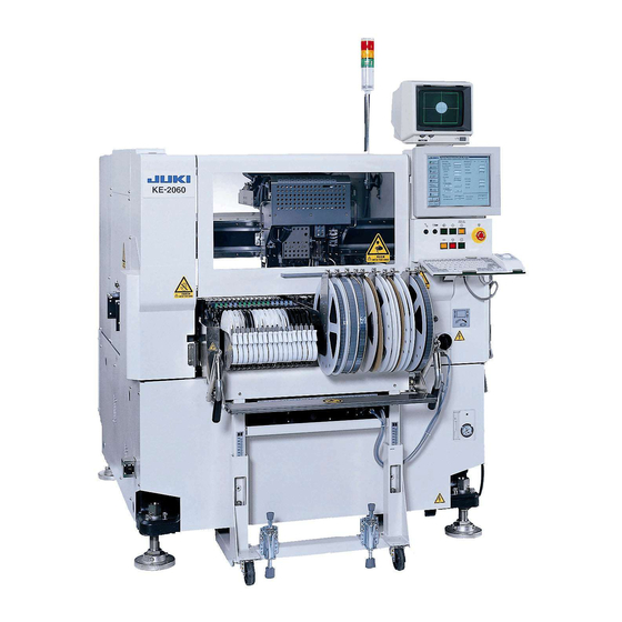
High-Speed Modular Mounter Maintenance Guide
X-Y UNIT
Procedures for replacing and adjusting components within the X-Y unit, including belts and pulleys.
HEAD UNIT
Maintenance and replacement procedures for various head unit components like motors, sensors, and belts.
PARTS AROUND THE HEAD
Covers replacement and adjustment of parts located around the head unit, such as ejector and HMS.
OCC Assembly
Procedures for replacing and adjusting OCC assembly components like cameras, lenses, and light boards.
BOARD TRANSPORT UNIT
Maintenance and replacement procedures for the board transport unit, including belts, motors, and sensors.
CAL BLOCK
Procedures for replacing components related to the CAL BLOCK, such as board assemblies and ejectors.
ATC
Maintenance and adjustment procedures for the ATC unit, including air cylinders and speed controllers.
VCS
Procedures for replacing VCS components like CCD cameras, lenses, and light boards.
FEEDER BANK AND REPLACEMENT TABLE (OPTIONAL)
Maintenance and adjustment of feeder bank and replacement table components, including cylinders and sensors.
PNEUMATIC UNITS
Procedures for replacing pneumatic unit components like pressure detection cables and filter elements.
SWITCHES
Procedures for replacing various switches, including push-button, emergency stop, and cover open switches.
REPLACING AND ADJUSTING THE FEEDER FLOAT SENSOR
Guides for replacing and adjusting the feeder float sensor, including height and light axis alignment.
OTHER UNITS
Procedures for replacing various other units, including CRT, FDD, CD-ROM, LCD, and HDD.
ELECTRICAL COMPONENTS
Layout and structure of electrical components, including control unit and power supply unit diagrams.
AUTO BOARD WIDTH ADJUSTMENT
Procedures for assembling and adjusting the auto board width adjustment components.
FEEDER POSITION INDICATOR
Procedures for detaching the FPI (Front and Rear) from the machine main unit.
KE2000/2000R JIG LISTS
A list of jigs used for KE2000/2000R series, including part numbers and purposes.
Need help?
Do you have a question about the KE-2060 and is the answer not in the manual?
Questions and answers