Table of Contents
Advertisement
Advertisement
Table of Contents

Subscribe to Our Youtube Channel
Related Manuals for TDT RZ2


Summary of Contents for TDT RZ2
- Page 1 ystem anual Updated: 5/8/18...
- Page 2 The information contained in this document is provided “as is,” and is subject to being changed, without notice. TDT shall not be liable for errors or damages in connection with the furnishing, use, or performance of this document or of any information contained herein.
-
Page 3: Table Of Contents
System 3 Manual Table of Contents Part 1: RZ Z‐Series Processors RZ2 BioAmp Processor .............................1 ‐ 3 RZ5D BioAmp Processor..........................1 ‐ 17 RZ5P Fiber Photometry Processor ......................1 ‐ 27 RZ6 Multi I/O Processor ..........................1 ‐ 35 RZ5 BioAmp Processor ..........................1 ‐ 51 RZ‐UDP Communications Interface......................1 ‐ 63 Part 2: Data Streamers RS4 Data Streamer.............................2 ‐ 3 PO8e Streaming Interface for the RZ ...................... 2 ‐ 27 Part 3: RX Processors RX8 Multi I/O Processor ..........................3 ‐ 3 RX6 Multifunction Processor........................3 ‐ 13 RX5 Pentusa Base Station ..........................3 ‐ 25 RX7 Stimulator Base Station........................3 ‐ 35 Part 4: RP Processors RP2.1 Real‐Time Processor ..........................4 ‐ 3 RA16BA Medusa Base Station........................4 ‐ 9 RV8 Barracuda Processor ..........................4 ‐ 13 Part 5: RM Mobile Processors RM1/RM2 Mobile Processors.........................5 ‐ 3... - Page 4 System 3 RA8GA Adjustable Gain PreAmp........................ 6 ‐ 89 Headstage Connection Guide ........................6 ‐ 93 TB32 32‐Channel Digitizer.......................... 6 ‐ 97 PZ5‐BAT External Charger ........................6 ‐ 101 PZ‐BAT External Battery Pack for the PZ Amplifiers ..............6 ‐ 105 Part 7: Stimulus Isolator IZ2/IZ2H Stimulator............................7 ‐ 3 IZ2M/IZ2MH Stimulator..........................7 ‐ 21 MS4/MS16 Stimulus Isolator ........................7 ‐ 33 Part 8: Video Processor RV2 Video Processor............................8 ‐ 3 RVMap Software for RV2..........................8 ‐ 21 Part 9: MicroElectrode Array Interface MZ60 MicroElectrode Array Interface .......................9 ‐ 3 Part 10: High Impedance Headstages ZIF‐Clip® Analog Headstages ........................10 ‐ 3 ZIF‐Clip® ZD Digital Headstages ......................10 ‐ 13 ZIF‐Clip® ZCD Digital Headstages......................10 ‐ 21 ZIF‐Clip® Headstage Holders ........................10 ‐ 29 Acute (Non‐ZIF) Headstages........................10 ‐ 33 Chronic (Non‐ZIF) Headstages.........................10 ‐ 41 ECoG Headstages............................10 ‐ 45 SH16 Switchable Headstages ........................10 ‐ 47 Part 11: Low Impedance Headstages Low Impedance Headstages........................
- Page 5 System 3 Part 14: Attenuator PA5 Programmable Attenuator......................... 14 ‐ 3 Part 15: Commutators ACO32/ACO64 Motorized Commutators....................15 ‐ 3 Part 16: Transducers and Amplifiers MF1 Multi‐Field Magnetic Speakers......................16 ‐ 3 EC1/ES1 Electrostatic Speaker ........................16 ‐ 9 ED1 Electrostatic Speaker Driver ......................16 ‐ 15 HB7 Headphone Buffer ..........................16 ‐ 17 MA3 Microphone Amplifier........................16 ‐ 21 MS2 Monitor Speaker ..........................16 ‐ 25 SA1 Stereo Amplifier ............................16 ‐ 27 SA8 Eight Channel Power Amplifier ....................16 ‐ 29 FLYSYS FlashLamp System ........................16 ‐ 33 CF1/FF1 Magnetic Speakers ........................16 ‐ 37 Part 17: Subject Interface RBOX Response Box ............................17 ‐ 3 HTI3 Head Tracker Interface ........................17 ‐ 9 BBOX Button Box ............................17 ‐ 17 BH32 Behavioral Cage Controller......................17 ‐ 25 Part 18: Signal Handling FB128 Neural Simulator ..........................
- Page 6 System 3 Part 21: System 3 Utilities zBUSmon Interface Testing Software ..................... 21 ‐ 3 Corpus System 3 Hardware Emulator ....................21 ‐ 11 Part 22: Computer Workstation WS4/WS8 High Performance Computer Workstation ..............22 ‐ 3...
-
Page 7: Part 1: Rz Z-Series Processors
Part 1: RZ Z‐Series Processors... - Page 8 System 3...
-
Page 9: Rz2 Bioamp Processor
256 channels at sampling rates up to ~25 kHz and 128 channels at sampling rates up to ~50 kHz. The RZ2 also features 16 channels of analog I/O, 24 bits of digital I/O, two Legacy optical inputs for Medusa PreAmps, and an onboard LCD for system status display. - Page 10 Software Control Synapse software controls the RZ2 and provides users a high level interface for device configuration. Device programming is implemented with circuit files developed using TDT's RP Visual Design Studio (RPvdsEx). Circuits are loaded to the processor through TDT run- time applications or custom applications.
- Page 11 System 3 Touch to Display: DSP #1 Details Firmware Version: Model: RZ2 Bioamp Processor DSP Type: Quad Core DSP Sample Rate: 12 kHz (24414.0625 Hz) Time Slice: Component Usage: 0 of 768 Max Core Cycle Use: Optical Config: None Memory Usage: XM =>...
- Page 12 Note: Older versions of the RZ2 have a selection knob that allows the user to highlight a section of the screen. To display more detailed information, rotate the knob to select a system component and then push the knob to show the information view.
- Page 13 System 3 RZ2 Multi‐DSP Architecture Functional Diagram As shown in the diagram above, the RZ2 architecture consists of three functional blocks: The DSPs Each DSP in the DSP Block is connected to a local interface to the four data buses: two buses that connect...
- Page 14 DSP and the Data Pipe Bus. Distributing Data Across DSPs For the best performance, processing tasks must be efficiently distributed across the available DSPs. That means transferring data across DSPs. The RZ2 architecture provides three data buses for this type of data handling. The Data Pipe Bus The Data Pipe bus is optimized for handling high count multi-channel data streams and efficiently transfers up to 256 channels of data between DSPs.
- Page 15 As with other devices, your expected sustained RZ-to-Host PC data rate should not exceed 1/2 to 2/3 of the rated data transfer speed. For the RZ2 device this is 160 Mbits/second (Mbps) so your designs should have a sustained data rate of no...
- Page 16 1-10 System 3 more than ~100 Mbps. When the RZ2 is processing, the current data transfer rate (Mbps) is displayed in the top right corner of the LCD Screen. This maximum rate may be further limited by your PC’s ability to store the data to disk.
- Page 17 .000833 Onboard Analog I/O The RZ2 is equipped with eight channels of 16-bit PCM D/A and eight channels of 16-bit PCM A/D. All 16 channels can be accessed via front panel BNCs marked Port D and Port E or via a 25-pin analog I/O connector. See “RZ2 Technical Specifications”...
- Page 18 (A, B, and C) as described in the chart below. All digital I/O lines are accessed via the 25-pin connector on the front of the RZ2 and ports A and C are available through BNC connectors on the front panel.
- Page 19 See “RZ-UDP Communications Interface” on page 1-63, for more information. Note: If the RZ2 has 4 optical DSP cards (see below) installed, the UDP Serial port is not available. Specialized DSP/Optical Interface Boards (Optional) The RZ standard DSP boards can be replaced with specialized DSP boards which include an optical interface for communication and control of RZ compatible devices, such as the IZ2 Stimulator and RS4 Data Streamer.
- Page 20 Legacy (Medusa) Up to four, one per QZDSP_Opt or Specialty DSP card Add-on Specialty (Optional) upgrade. 8 programmable bits: 3.3 V, 25 mA max load Digital I/O 2 programmable bytes (16 bits): 5.0 V, 35 mA max load RZ2 BioAmp Processor...
- Page 21 DB25 Analog I/O Pinout Analog In Analog Out AGND Name Description Name Description Not Used Not Used AGND Analog Ground Analog Input Channels Analog Input (Port D) Channels (Port D) Analog Output Channels Analog Output (Port E) Channels (Port E) RZ2 BioAmp Processor...
- Page 22 Bits 0, 2, 4 and 6 Digital I/O Bits 1, 3, 5 and 7 Port B Word Addressable Port B Digital I/O Word Addressable Bits 0, 2, 4 and 6 Digital I/O Bits 1, 3, 5 and 7 RZ2 BioAmp Processor...
-
Page 23: Rz5D Bioamp Processor
Data can be input from a PZ amplifier or digital headstage manifold at a sampling rate of up to ~50 kHz. The RZ5D also supports microstimulation applications. The RZ5D can be used with TDT’s IZ2 stimulus isolator for up to 128 channels of stimulation and switching headstages (SH16-Z) to comprise a complete microstimulation system. - Page 24 Software Control TDT Synapse software controls the RZ5D and provides users a high level interface for device configuration. Device programming is implemented with circuit files developed using TDT's RP Visual Design Studio (RPvdsEx). Circuits are loaded to the processor through TDT run-time applications or custom applications.
- Page 25 System 3 1-19 As shown in the diagram above, the RZ5D architecture consists of three functional blocks: The DSPs Each DSP in the DSP Block is connected to a local interface to the three data buses: two buses that connect each DSP to the other functional blocks and one that handles data transfer between the DSPs (as described further in “Distributing Data Across DSPs”...
- Page 26 1-20 System 3 In RPvdsEx data is transferred across the zHop bus using paired zHop components, including zHopIn, zHopOut, MCzHopIn, MCzHopOut, and MCzHopPick. Up to 126 pairs can be used in a single RPvdsEx circuit. Bus Related Delays The zHop bus introduces a two sample delay However, this delay is taken care of for the user in Synapse and in OpenEx (when Timing and Data Saving macros are used).
- Page 27 System 3 1-21 Note: When burning new microcode or if the firmware on the RZ5D is blank, the VFD screen will report a cycle usage of 99% and the processor status lights will flash red. Status Indicators Description Cyc: cycle usage (note: limited to 2 digits; ex: 110 displayed as 10) for QZDSPs, the highest core cycle usage is shown Bus%: percentage of internal device's bus capacity used...
- Page 28 1-22 System 3 IZ Stimulator Port The output port labeled IZ can be used to transfer microstimulation waveforms to the IZ2 Stimulator and/or to control an attached SH16-Z switching headstage. This port can output up to 128 channels of stimulation at a maximum sampling rate of ~50 kHz.
- Page 29 System 3 1-23 RPvdsEx Manual See the “Digital I/O Circuit Design” section of the for more information on programming the digital I/O. Digital I/O Description DB25 BNCs Notes Byte A bits 0 - 7 byte addressable Byte B bits 0 - 7 byte addressable Byte C bits 0 - 7...
- Page 30 1-24 System 3 Digital I/O These LEDs indicate the state of the 8 bit-addressable I/O of byte C. Light Pattern Description Dim Green Bit is configured for output and is currently a logical low (0) Solid Green Bit is configured for output and is currently a logical high (1) Dim Red Bit is configured for input and is currently a logical low (0) Solid Red...
- Page 31 System 3 1-25 82 dB (20 Hz - 20 kHz at 9.9 V) S/N (typical) 10 Ohms Output Impedance 4 channels, 16-bit PCM Up to 48828.125 Hz Sample Rate DC - 7.5 kHz (3 dB corner, 2nd order, 12 dB per Frequency Response octave) +/- 10.0 Volts...
- Page 32 1-26 System 3 DB25 Analog I/O Pinout Analog Out Analog Out AGND Name Description Name Description Not Used Not Used AGND Analog Ground Analog Input Channels Analog Input Channels Not Used Not Used Analog Output Channels Analog Output Channels Not Used Not Used DB25 Digital I/O Pinout Byte B Byte A...
-
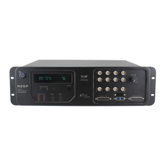
Page 33: Rz5P Fiber Photometry Processor
Software Control The RZ5P is intended for use with TDT’s Synapse software. When custom control is required, see the RZ5D BioAmp Processor section in this manual for details on developing circuits in the System 3’s RPvdsEx circuit design software. Note: PZ related macros should be moved to DSP-2 for the RZ5P. - Page 34 1-28 System 3 Fiber Photometry Connections On the front panel of the RZ5P, connect photo sensors to ADC BNCs 1 and 2 and connect light drivers to DAC BNCs 9 - 12. Fiber Photometry System Connection Diagram The Analog I/O DB25 connector can also be used for the connections. See “DB25 Analog I/O Pinout”...
- Page 35 System 3 1-29 The front panel VFD screen reports detailed information about the status of the system. The display includes two lines. The top line reports the system mode, Run!, Idle, or Reset, and displays heading labels for the second line. The second line reports the user’s choice of status indicators for each DSP followed by an aggregate value.
- Page 36 1-30 System 3 BNC connectors on the front panel labeled Digital. See “RZ5P Technical Specifications” on page 1-31, for the DB25 pinout and BNC channel mapping. Digital I/O Description DB25 BNCs Notes Byte A bits 0 - 7 byte addressable Byte B bits 0 - 7 byte addressable...
- Page 37 System 3 1-31 Light Pattern Description Dim Green Analog I/O channel signal voltage is less than +/-5 V Solid Green Analog I/O channel signal voltage is between +/-5 V to +/-9 V Solid Red Analog I/O channel clip warning (voltage greater than +/-9 V) UDP Ethernet Interface (Optional) The RZ UDP Ethernet interface is designed to transfer data to or from a PC.
- Page 38 1-32 System 3 BNC Channel Mapping Please note channel numbering begins at the top left block of BNCs for both analog and digital I/O and is printed on the face of the device to minimize miswiring. Maps to: Ch 1-4 Analog In Ch 9-12 Analog Out Port C...
- Page 39 System 3 1-33 DB25 Digital I/O Pinout Byte B Byte A Byte C Name Description Pin Name Description Byte C Byte C Bit Addressable Bit Addressable Digital I/O Digital I/O Bits 0, 2, 4, and 6 Bits 1, 3, 5, and 7 Digital I/O Ground Byte A Word Addressable Byte A...
- Page 40 1-34 System 3 RZ5P Fiber Photometry Processor...
-
Page 41: Rz6 Multi I/O Processor
1-35 RZ6 Multi I/O Processor RZ6 Overview The RZ6 Multi I/O Processor is a high sample rate processor with flexible input/ output capabilities. The RZ6 features up to four digital signal processors cards; any card can be either a single standard processor card (RZDSP) or a quad-core processor card (QZDSP). - Page 42 Software Control TDT Synapse or BioSigRZ software controls the RZ6 and provides users a high level interface for device configuration. Device programming is implemented with circuit files developed using TDT's RP Visual Design Studio (RPvdsEx). Circuits are loaded to the processor through TDT run-time applications or custom applications.
- Page 43 System 3 1-37 As shown in the diagram above, the RZ6 architecture consists of three functional blocks: The DSPs Each DSP in the DSP block is connected to three data buses: two buses that connect each DSP to the other functional blocks and one that handles data transfer between the DSPs (the zHop Bus).
- Page 44 1-38 System 3 Functional Signal Flow Diagrams The following diagrams illustrate how analog signals for channels A and B flow through the RZ6 and its modules. For more information on analog input and output see “Onboard Analog I/O and Optional Amplifier Input” on page 1-39. The diagram to the below depicts the analog input flow for the RZ6.
- Page 45 System 3 1-39 RZ6 Features Onboard Analog I/O and Optional Amplifier Input The RZ6 is equipped with onboard analog I/O and may also include a fiber optic port for Medusa preamplifier input. The following table provides a quick overview of the analog I/O and amplifier input features and how they must be accessed during circuit design. The RZ6 relies exclusively on macros for configuring analog and digital I/O and its fiber optic input RPvdsEx Manual port.
- Page 46 1-40 System 3 A and B Microphone Amplifier An onboard two channel amplifier provides gain for the onboard analog input signals (MIC-A, DIFF-A, In-A, and In-B). The switch located to the left of the gain control knob allows the current gain setting to be applied (if set to Amp) or bypassed completely (if set to Byp).
- Page 47 Analog Output via BNCs DAC channels A and B are output to BNCs labeled Out-A and Out-B after attenuation has been applied. These outputs use a stereo power amplifier to drive TDT’s MF1 multi- function speakers. Note: A single signal generated or input from any of the RZ6 analog inputs can be ganged to reduce the spectral variation in power of the transducer across all frequencies (see “D/A Power Output Diagram”...
- Page 48 4-pin, mini-DIN connectors is used to enable or disable output of DAC channels A and B. Note: The electrostatic speaker driver is designed to work exclusively with TDT’s electrostatic series speakers. Do NOT attempt to use any other speaker. Important! If the electrostatic speaker driver is not being used, make sure that the ON/OFF switch is in the OFF position to reduce noise on the RZ6.
- Page 49 System 3 1-43 (serial number < 2000) were limited to 8 bits. By default, all lines are configured as inputs. Data direction is configured using the RZ6_Control macro in RPvdsEx and may be controlled dynamically through the macro input port. For more information on using the RZ6_Control macro see the help provided in the macro's properties dialog box.
- Page 50 1-44 System 3 Important! The status lights flash when a DSP goes over the cycle usage limit, even if only for a cycle. This helps identify periodic overages caused by components in time slices. Front Panel VFD Screen The front panel VFD screen reports detailed information about the status of the system.
- Page 51 System 3 1-45 Light Pattern Description s Lit Input is ≤ -6 dB down from max input voltage Input is between -6 dB and -12 dB down from max input voltage Input is between -12 dB and -25 dB down from max input voltage Input is between -25 dB and -50 dB down from max input voltage Digital I/O LED Indicators...
- Page 52 1-46 System 3 +/- 10.0 Volts, 175 mA max load Voltage Out 115 dB (20 Hz - 80 kHz at 5 Vrms) S/N (typical) -90 dB (1 kHz output at 5 Vrms) THD (typical) 31 (Serial numbers > 2000) Sample Delay 47 (Serial numbers <...
- Page 53 System 3 1-47 115 dB (20 Hz to 80 kHz) Signal Noise < 0.02% at 1 Watt from 50 Hz to 100 kHz 20 μV rms Noise Floor 10 kOhm Input Impedance 1 Ohm Output Impedance 0.5 Ohm ganged 2 channels Headphone Output 1 Ohm Output Impedance...
- Page 54 1-48 System 3 DB25 Digital I/O Pinout Name Description Name Description Byte C Byte C Bit Addressable digital Bit Addressable digital Bits 0, 2, 4, and 6 Bits 1, 3, 5, and 7 Digital I/O Ground Byte A Word addressable digital Byte A Word addressable digital Bits 0, 2, 4, and 6 Bits 1, 3, 5, and 7...
- Page 55 System 3 1-49 Digital I/O – DB9 Connector Pinout Note: Serial numbers < 2000 only. Pins Name Description Name Description Digital I/O Ground 0, 2, 4, 6 Digital I/O bits 1, 2, 3, 5, 7 Ground RZ6 Multi I/O Processor...
- Page 56 1-50 System 3 RZ6 Multi I/O Processor...
-
Page 57: Rz5 Bioamp Processor
Data can be input from two Medusa preamplifiers at a sampling rate of ~25 kHz. The RZ5 also supports microstimulation applications. The RZ5 can be used with one of TDT's stimulus isolators (MS16 or MS4) to comprise a complete microstimulation system. For more information, see “MS4/MS16 Stimulus Isolator” on page 7-33. - Page 58 1-52 System 3 time applications or custom applications. This manual includes device specific information needed during circuit design. For circuit design techniques and a complete reference of the RPvdsEx circuit components, see “MultiProcessor Circuit Design” and RPvdsEx Manual “Multi-Channel Circuit Design” in the RZ5 Architecture The RZ5 processor utilizes a multi-bus architecture and offers three dedicated, data buses for fast, efficient data handling.
- Page 59 System 3 1-53 The zBus Interface The zBus Interface provides a connection to the PC. Data and host PC control commands are transferred to and from the DSP Block through the zBus Interface Bus, allowing for large high-speed data reads and writes without interfering with other system processing.
- Page 60 1-54 System 3 LED will be lit dim green if the cycle usage on a DSP is 0%. If the demands on a DSP exceed 99% of its capacity on any given cycle, the corresponding LED will flash red (~1 time per second). Front Panel VFD Screen The front panel VFD screen reports detailed information about the status of the system.
- Page 61 System 3 1-55 The following table provides a quick overview of the amplifier and analog I/O features and how they must be accessed during circuit design. When the RZ5_AmpIn_MC and RZ5_AmpIn macros are not used, reference the table and be sure to use the appropriate component, channel offset, scale factor and so forth.
- Page 62 1-56 System 3 Fiber Oversampling (acquisition only) The fiber optic cable that carries the signals to the fiber optic input ports on the RZ5 has a transfer rate limitation of 6.25 Mbits/s. With 16 channels of data and 16 bits per sample, this limitation translates to a maximum sampling rate of ~25 kHz. However, the need may arise to run a circuit at a higher sampling rate while still acquiring data via a fiber optic port.
- Page 63 System 3 1-57 Double-click the macro to access the settings on the Digital I/O tab. The RZ5_Control macro also offers a Direction Control Mode parameter that enables the macro inputs and allows the user to control data direction dynamically. For more information on using the RZ5_Control macro see the help provided in the macro's properties dialog box.
- Page 64 1-58 System 3 Analog I/O ‐ A Inputs and DAC Outputs A and DAC LED indicators are labeled and located to the right of the byte C LED indicators. Light Pattern Description Analog I/O channel signal voltage is less than +/-100 mV Analog I/O channel signal voltage is less than +/-5 V Dim Green Solid Green Analog I/O channel signal voltage is between +/-5 V to +/-9 V...
- Page 65 System 3 1-59 RZ5 Technical Specifications Note: Technical Specifications for amplifier A/D converters are found under the preamplifier's technical specifications. 400 MHz DSPs, 2.4 GFLOPS peak per DSP One or Two 64 MB SDRAM per DSP Memory 4 channels, 16-bit PCM Up to 48828.125 Hz* Sample Rate DC - 0.44*Fs (Fs = sample rate) Frequency Response...
- Page 66 1-60 System 3 Maps to: Ch 1-4 Analog In Ch 9-12 Analog Out Port C Bits 0-3 Digital I/O DB25 Analog I/O Pinout Analog Out Analog Out AGND Name Description Name Description Not Used Not Used AGND Analog Ground Analog Input Channels Analog Input Channels Analog Output Channels Analog Output Channels RZ5 BioAmp Processor...
- Page 67 System 3 1-61 DB25 Digital I/O Pinout Byte B Byte A Byte C Name Description Name Description Byte C Byte C Bit Addressable Bit Addressable Digital I/O Digital I/O Bits 0, 2, 4, and 6 Bits 1, 3, 5, and 7 Digital I/O Ground Byte A Word Addressable Byte A...
- Page 68 1-62 System 3 RZ5 BioAmp Processor...
-
Page 69: Rz-Udp Communications Interface
1-63 RZ‐UDP Communications Interface RZ2 Processor Back side with RZ‐UDP Installed RZ‐UDP Overview The RZ Communications Interface (RZ-UDP-20) is an optional interface for RZ processor devices that includes a UDP Ethernet connection and a serial port connection. The serial port can support baud rates up to 115200. The port is a standard 9-pin RS232 connection located on the back of the RZ. - Page 70 UDP object. See the Synapse manual for more information. The TDT drivers installation provides the UDP test application here: C:\TDT\RPvdsEx\Examples\RZ UDP\ For RPvdsEx circuit design, two macros designed for the UDP Ethernet interface and...
- Page 71 System 3 1-65 information. Status LEDs The UDP Ethernet interface provides several status indicators which are located on the back of the RZ processor. These status indicators are used to denote a proper connection to a network, activity or network traffic, or UDP activity such as sending or receiving packets.
- Page 72 1-66 System 3 Network Address All network devices utilize a network address commonly referred to as the “IP address”. The IP address is a unique address given to any networked device and consists of four hexadecimal values that are used to locate a device from within a network.
- Page 73 System 3 1-67 Class Start Default Subnet Mask Class C 192.0.0.0 223.255.255.255 255.255.255.0 Class A defined networks contain a broad range of possible values since the subnet mask allows for 24 bits or 16,777,214 addresses per network. A Class C network contains 8 bits of IP addresses per network and so, allows up to 256 possibilities.
- Page 74 1-68 System 3 Manual In manual mode the IP address is selected by the client (manually by the user or any other means) and the DHCP protocol messages are used to inform the server that the address has been allocated. The UDP Protocol UDP or “User Datagram Protocol”...
- Page 75 UDP Ethernet interface will use this standard NetBIOS Name structure: TDT_UDP_MD_XXXX the model of the device, e.g. '2' for an RZ2, '5' for an RZ5, '6' for an RZ6, 'D' for an RZ5D the number of RZ processor DSPs...
- Page 76 1-70 System 3 Configuring the UDP through the Web Interface Every RZ UDP interface contains a minimal web server which is used to configure the UDP and serial interfaces. Configuration options can be set here if no DHCP server is available. If a DHCP server exists, the NetBIOS name associated with the dynamically assigned IP address can be configured here.
- Page 77 System 3 1-71 Note: Any server pages that modify the device configuration require a username and password. Default Username: admin Default Password: pw To change the Username and Password: Click the Authentication link on the left side of the UDP server web page. You will be prompted to enter the current username and password.
- Page 78 1-72 System 3 Current Network Value Current IP settings are displayed in this area. Settings for configuring the static IP address, subnet mask, gateway address, and MAC address are located in the “Network Settings” area. Network Settings This area contains settings for configuring the UDP interface in the event that no DHCP server is detected.
- Page 79 \ / : * ? " ; | - Note: A reset circuit is provided with the TDT driver installation and can be found in: C:/TDT/RPvdsEx/Support/ Running this circuit on the device with the UDP interface will reset the NetBIOS name to the factory default setting described on “NetBIOS Name”...
- Page 80 1-74 System 3 8. Click OK. The UDP interface connection should now be recognized by the PC. Cycle power on the RZ device, the IP address of the RZ will be 10.1.0.100. To initialize the PC for a direct connection in Windows XP: Physically connect the UDP interface and the PC via an Ethernet crossover cable.
- Page 81 System 3 1-75 7. Click OK. The UDP interface connection should now be recognized by the PC. Cycle power on the RZ device, the IP address of the RZ will be 10.1.0.100. Serial Configuration The Serial Configuration page on the web interface contains settings for configuring the serial interface.
- Page 82 1-76 System 3 Parameters The user can enable/disable the serial port, specify the baud rate, and select from a list of preset values. Data Type Big vs Little Endian If the device attached to the RS232 connection sends the lower byte before the upper byte, set this to Little Endian. Otherwise, use Big Endian. 8 vs 16 vs 24 vs 32 bit words This field specifies the length of the data words that the device attached to the RS232 connection is sending.
- Page 83 System 3 1-77 sequence of bytes at the beginning of each frame. The user can enter a decimal value or any ASCII character in single quotes (e.g. ‘A’). The ‘*’ character is reserved as a wilard character that will match anything. Note: If the received data/headers do not match the expected format, they are discarded and all synchronization information is reset.
- Page 84 1-78 System 3 4 byte header + (16 channels x 4 bytes) = 68 bytes. Header Format The packet header precedes a new packet and stores information about the packet and its intended command for the UDP interface. The structure for the packet header is shown below.
- Page 85 System 3 1-79 packet size) set in the macro setup properties dialog. The macro accepts a multi- channel data stream as well as a logic input that tells the macro to send out a packet. An output labeled “Busy” indicates if the macro is currently in the process of sending out a packet.
- Page 86 1-80 System 3 Receiving Scalar Data Construct When data is received, the NewPack signal will output a logic high (1) for one sample denoting that a packet header has been found. As data is being received, the Busy signal will output logic high (1). The Busy signal will then remain high until the entire packet has been received.
- Page 87 System 3 1-81 RZ_Serial_Rec Macro The RZ_Serial_Rec macro is used to receive serial data from the RS232 connection and can also be triggered to send preset commands over the RS232 connection. The number of channels received by the hardware is set in the web configuration. Make sure the packet size set in the macro is at least as large as the value set in the web configuration, otherwise some channels will have missing or incorrect data.
- Page 88 RZ multi-processor device. The UDP Test Application was written in MSVC++ to illustrate the portability of the UDP Ethernet interface. The UDP Test Application is installed to: C:\TDT\RPvdsEx\Examples\RZ UDP\ Running the Application Once the application is running, connecting to a UDP interface and sending, or receiving packets from an RZ processor is extremely easy.
- Page 89 System 3 1-83 To load an existing packet configuration: Select Open from the File menu. 2. Browse to the desired *.hex file and click the Open button. The specified *.hex file will now display any packet information. To save a packet configuration: Select Save or Save As from the File menu.
- Page 90 1-84 System 3 To send a data packet to the RZ processor: Double-click anywhere in the Test Application packet window. Right-click to bring up a selection dialog box and select New Packet. This prompts a dialog box where values can be edited. 2.
- Page 91 System 3 1-85 4. Click the Send All button to send all data packets to the RZ processor. Send an individual packet by right-clicking on the desired packet and selecting Send Packet from the Packet Dialog menu. The status bar displays that the packet was sent to the RZ processor. Data packets are received through RPvdsEx using the RZ_UDP_Rec macro.
- Page 92 1-86 System 3 The Test Application runs separate threads for sending and receiving data so it is possible to listen (wait for a data packet to be received) while sending, connecting to a device, or disconnecting from a device. Writing a Custom Software Application The Test Application is designed to be used as a diagnostic tool for the UDP Ethernet Interface.
- Page 93 System 3 1-87 # configure the header. Notice that it includes the header # information followed by the command 2 (set remote IP) # and 0 (no data packets for header). packet = struct.pack('4B', 0x55, 0xAA, CMD_SET_REMOTE_IP, # Sends the packet to the UDP interface, setting the remote IP # address of the UDP interface to the host PC sock.send(packet)
- Page 94 1-88 System 3 packet = struct.pack(">%di" % len(data), *(i for i in data)) # send the data packet to the UDP interface. print 'sending packet', count, '...' sock.send(header + packet) count += 1 # slow it down for demonstration purposes time.sleep(.2) UDP Interface Performance The UDP interface is a 10Mb Ethernet interface, but the usable bandwidth is...
- Page 95 System 3 1-89 Typical RZ Transmission Performance with the RZUDP‐20 Table The table below displays the expected throughput for different numbers of packets sent or received per second depending on the number of channels transmitted on an RZ processor. Number of Channels Packets Sent/Received (32-bit Words) per Second Technical Specifications ...
- Page 96 1-90 System 3 RZ-UDP Communications Interface...
-
Page 97: Part 2: Data Streamers
Part 2: Data Streamers... - Page 98 System 3...
-
Page 99: Rs4 Data Streamer
Data is transferred to the RS4 through its streaming ports located on the back panel of the device. A special version of the RZ2 provides matching ports used to connect and stream data to the RS4. These ports ensure fast and reliable data transfer from the RZ2 and are color coded for correct wiring. - Page 100 Design Studio (RPvdsEx) on the RZ2 processor through TDT run-time applications such as OpenEx or custom applications. A single RPvdsEx storage macro is provided to configure the RZ2 to send data to the RS4. Once connected to the RZ2, a properly configured RS4 will automatically store the data it receives.
- Page 101 Recording Sessions When an RZ2 begins streaming data to the RS4, a recording period or session is initiated. A session is defined as any length of continuous streaming data sent to an RS4 streaming port. Each streaming port on the RS4 can initiate a session and sessions may run concurrently.
- Page 102 System 3 Setting‐Up Your Hardware Basic setup for the RS4 Data Streamer includes connection to one or more RZ2 BioAmp Processors. Optionally, an Ethernet connection for direct connection to a PC or network is supported. Connect the RZ2 as illustrated in the following diagram.
- Page 103 System 3 Configuring the RS4 Default configuration settings allow the RS4 to begin streaming data immediately. The RS4 supports the DHCP (Dynamic Host Configuration) protocol for automatic configuration of network parameters. Once connected to an active network, the RS4 will attempt to lease an IP address. The DHCP Protocol DHCP or “Dynamic Host Configuration Protocol”...
- Page 104 System 3 2. Touch the Configure Manually check box and click OK to accept the default value. Using Windows 7 To access the RS4 file system through a PC, running Windows 7: 3. You will have to configure the PC TCP/IP settings. Open Control Panel then double-click Network and Sharing Center.
- Page 105 System 3 a. Press the Ports tab on the RS4 interface. b. The device address is displayed at the top of the page to the right of Device Name field. 11. Enter the device address as shown in a windows address bar to access the RS4 file system.
- Page 106 2-10 System 3 6. Click OK. The RS4 can now be accessed by the PC. 7. Obtain the RS4 device address. Press the Ports tab on the RS4 interface. The device address is displayed at the top of the page to the right of Device Name field.
- Page 107 These features allow single and multi-channel data to be copied and pasted directly into any OpenEx Data Tank folder. Naming Convention When connected to an active network, TDT’s OpenEx software sends information to the RS4 via a broadcast UDP packet allowing it to properly name the streaming data sent to the RS4.
- Page 108 2-12 System 3 For example, if you are recording channel 1 for the event wavA on Block-3 from DemoTank2 the RS4 will store in the following location and format: \data\DemoTank2\Block-3\DemoTank-Block-3_wavA_ch1.sev Without the OpenEx network information the RS4 falls back to the default data format: \data\Event name-year-month-day-hour-minute-second\unnamed.sev Note:...
- Page 109 RS4 (“Storage Tab” on page 2-15 for more information on deleting data). After moving, the data can be processed using one of TDT’s Data Tank applications (such as OpenExplorer). To access the data using these applications simply select the associated block then select the event name (in this case Block-1 and wavA).
- Page 110 2-14 System 3 Note: If the RS4 becomes unresponsive and fails to shutdown normally, you can shut the device down by holding the power button for longer than five seconds. This will force the device to shutdown. After a forced shutdown, the RS4 may perform a file system check.
- Page 111 System 3 2-15 Rate: Displays the approximate current data transfer rate in kB/s. This rate incorporates overheads in the data transfer protocol and may differ slightly from the data rate calculated by the macro. Amount Saved: Displays the amount of data saved to the storage array during the current recording session.
- Page 112 2-16 System 3 Local Storage: Data items stored on the RS4 storage array are populated in the local storage list. Multiple items may be selected using press and drag techniques. Select All: Press to select all items in the list. Deselect All: Press to deselect all items in the list.
- Page 113 System 3 2-17 Status Tab The Status tab provides system information such as processor usage rates, core temperatures, fan speeds, device IP address, array reformat progress, memory buffer allocation, and communication errors. Log information can also be retrieved from this tab. System: Displays important system status information.
- Page 114 You can stop the disk check at any time by pressing the Check button again. TDT recommends performing a disk check on a mirrored configuration every 7-30 days. Data Ports: Displays storage information for all installed memory buffers and any communication errors present.
- Page 115 System 3 2-19 Note: Individual comments can be saved as well. Use standard drag techniques to highlight the desired comment(s) and click Save to write the selection to the log.txt file. Config Tab The Config tab provides options for reformatting the currently installed storage array, updating the RS4 firmware, and rebooting the system.
- Page 116 Update Firmware: Press to update the RS4 firmware. Firmware is downloaded from the TDT server and automatically installed on the RS4. Connection to a network that has Internet connectivity is required to retrieve any updates.
- Page 117 It does NOT display available space on the media. Note: TDT recommends that you do not attempt to copy or move files using the USB ports while a recording session is active. Device Status LEDs The device status LEDs report streaming or network activity.
- Page 118 To enable, simply ensure that the switch is in the “1” position and attempt to power on the RS4. If the device does not power up after verifying that the power supply is enabled contact TDT. Can’t Access the RS4 Storage Array...
- Page 119 TDT recommends removing unnecessary data remaining on the storage array. RS4 Is Not Correctly Naming Data When connected to an active network, TDT’s OpenEx software sends information to the RS4 via a broadcast UDP packet allowing it to properly name the streaming data sent to the RS4. If the RS4 is powered on before connecting the necessary network cables it may default to the basic naming format: \data\Event name-year-month-day-hour-minute-second\unnamed.sev...
- Page 120 Communication errors may result from wiring errors between the RZ2 and RS4. Cycling power on the RZ2(s) may fix the issue. Refer to the “RS4 to RZ2 Connection Diagram” on page 2-6 for a proper wiring example. If the wiring is correct this may indicate a bad fiber optic cable that will need to be replaced.
- Page 121 Data in these scenarios are most likely recoverable. If you encounter this issue contact TDT. You may attempt to recover the data by accessing the RS4 file system to move the data to a local PC prior to reformatting the array.
- Page 122 2-26 System 3 RS4 Data Streamer...
-
Page 123: Po8E Streaming Interface For The Rz
(PO8e) for real-time processing in custom applications. The PO8e card can be in the same computer as the TDT system, or in a dedicated computer. The RZ connects to the PO8e card via a special DSP (RZDSP-U). This DSP has an interface located on the back panel of the RZ processor and connects to the PO8e via orange fiber optic cables provided with the system. - Page 124 2-28 System 3 For RPvdsEx circuit design, the TDT drivers installs the PO8e circuit macro here: C:\TDT\RPvdsEx\Macros\Device\PO8e_Streamer\ The PO8eStreaming libraries and examples can be found in: C:\TDT\RPvdsEx\Examples\PO8e\ PO8e Hardware Requirements Basic requirements include a paired fiber optic cable, an RZ processor equipped with the RZDSP-U card.
- Page 125 System 3 2-29 Sending Data Construct Data is sent whenever the “Send” input receives a rising trigger (logic high (1)). Up to 256 channels can be sent on each Send signal. This occurs in one sample period. If the number of channels is greater than 256, data is sent in blocks and grouped together on the PO8e card’s buffer.
- Page 126 2-30 System 3 A typical PO8e access session for a client consists of five main steps: Run the circuit on the RZ device that streams to the PO8e card. 2. Call connectToCard to get a pointer to an available PO8e card. 3.
- Page 127 System 3 2-31 Returns: Pointer to PO8e instance. Sample Code This code sample creates a PO8e object pointing to the first card identified in the system. PO8e *card = PO8e::connectToCard(0); void *card = connectToCard(0); releaseCard Description: Free the PO8e card objects through this interface. It is done this way to ensure that in Windows the objects are freed from the correct heap context.
- Page 128 2-32 System 3 stopCollecting Description: Call this to stop collecting a data stream from the PO8e card. C++ prototype: void stopCollecting(); C prototype: void stopCollecting(void* card); Sample Code Description: This code sample stops data collection on a PO8e object. card->stopCollecting(); stopCollecting(card);...
- Page 129 System 3 2-33 size_t numSamples = card- >samplesReady(&stopped); if (stopped) PO8e::releaseCard(card); bool stopped; numSamples = samplesReady(card, &stopped); if (stopped) releaseCard(card); readChannel Description: Copy the data buffered for an individual channel. Note that this call does NOT advance the data pointer. Use calls to flushBufferedData to discard the data copied using this function.
- Page 130 2-34 System 3 The data will be grouped by channel and the number of samples returned applies to all channels. The user is responsible for ensuring that the buffer is large enough to hold nSamples * numChannels() * dataSampleSize() bytes. The optional offsets array should be nSamples long and will be populated with the data offset of each block.
- Page 131 System 3 2-35 Hardware Information Retrieval numChannels Description: Counts the number of channels in the current stream. This value is set in the Stream_Remote_MC macro. Changing the number of channels mid-stream triggers an error condition. C++ prototype: numChannels(); C prototype: numChannels(void* card); Returns: Number of channels in the current data stream.
- Page 132 = card->getLastError(); nChannels = getLastError(card); Examples The example files below are installed with the TDT drivers package. Files: C:\TDT\RPvdsEx\Examples\PO8e\PO8eTest.rcx, PO8eTest.exe, PO8e.h Hardware: RZ2 Real-Time Processor Overview: PO8eTest.exe connects to any PO8e card(s) in the PC, waits for a stream then displays the data rate that each PO8e card is receiving.
-
Page 133: Part 3: Rx Processors
Part 3: RX Processors... - Page 134 System 3...
-
Page 135: Rx8 Multi I/O Processor
Software Control Software control is implemented with circuit files developed using TDT's RP Visual Design Studio (RPvdsEx). Circuits are loaded to the processor through TDT run- time applications or custom applications. This manual includes device specific information needed during circuit design. - Page 136 System 3 RX Architecture Each RX multiprocessor device is equipped with either two or five digital signal processors (DSPs). The multi-DSP architecture allows processing tasks to be distributed across multiple processors and enables data to be transferred to the PC quickly and efficiently. The DSPs include one master and one or four auxiliary DSP(s).
- Page 137 System 3 Components such as MCzHopIn and MCzHopOut can be used for multi-channel signals while components such as zHopIn, zHopOut, and MCzHopPick are used with single-channel signals. Up to 126 pairs can be used in a single RPvdsEx circuit. Bus Related Delays The zHop Bus introduces a single sample delay.
- Page 138 System 3 Status Indicators Cyc: cycle usage Ovr: processor cycle overages Bus%: percentage of internal device's bus capacity used I/O%: percentage of data transfer capacity used Important! The status lights will flash (~3 times a second) to alert the user when a device goes over the cycle usage limit, even if only for a particular cycle.
- Page 139 System 3 Note: Block C can only be configured with outputs. Channel Numbers Starting with block A and ending with block C, channels are numbered sequentially from 1 to 24. The channel numbering is independent of whether the analog I/O board is an input or output. For example: The analog I/O of an RX8 that has four A/D’s in the first two slots of Block A and four D/A’s in the first two slots of Bank C, would be accessed with the A/D’s...
- Page 140 CAUTION!: The first eight bits of bit-addressable digital I/O on RX devices are unbuffered. When used as inputs, overvoltages on these lines can cause severe damage to the system. TDT recommends when sending digital signals into the device, never send a signal with amplitude greater than five volts into any digital input.
- Page 141 System 3 6. When the configuration is complete, click OK to return to the Set Hardware Parameters dialog box. Bit # Description Each of these bits controls the configuration of one of the eight addressable bits as inputs or outputs. Setting the bit to one will configure that bit as an output.
- Page 142 3-10 System 3 Sigma-Delta converters support a more limited set of sampling rates as shown in the table below. When using Sigma-Delta converters, the user must ensure a valid sampling rate is set for the device. Note: The Check Realizable button in the device set-up dialog in RPvdsEx is used to calculate the true sampling rate of the system when an arbitrary sampling rate is used.
- Page 143 †Note: See “Realizable Sampling Rates for the RX8” on page 3-9 for a list of supported sampling rates. Note: zBus chasis (ZB1PS) required for power and communication. DB25 Connector Pinouts TDT Recommends accessing the RX8 I/O via a PP24 patch panel. RX8 Multi I/O Processor...
- Page 144 3-12 System 3 Analog I/O Name Description Name Description Analog I/O Channels Analog I/O Channels Input or Output Input or Output Depending Depending on Custom on Custom Configuration Configuration AGND Analog Ground Analog I/O Channels Input or Output Depending on Custom Configuration Analog Outputs Analog Outputs...
-
Page 145: Rx6 Multifunction Processor
Software Control Software control is implemented with circuit files developed using TDT's RP Visual Design Studio (RPvdsEx). Circuits are loaded to the processor through TDT run- time applications or custom applications. This manual includes device specific information needed during circuit design. - Page 146 3-14 System 3 distributed across multiple processors and enables data to be transferred to the PC quickly and efficiently. The DSPs include one master and one or four auxiliary DSP(s). 128 MB SDRAM of system memory is shared by all DSPs. When designing circuits the maximum number of components for each RX DSP is 256.
- Page 147 System 3 3-15 Components such as MCzHopIn and MCzHopOut can be used for multi-channel signals while components such as zHopIn, zHopOut, and MCzHopPick are used with single-channel signals. Up to 126 pairs can be used in a single RPvdsEx circuit. Bus Related Delays ...
- Page 148 3-16 System 3 Status Indicators Cyc: cycle usage Ovr: processor cycle overages Bus%: percentage of internal device's bus capacity used I/O%: percentage of data transfer capacity used Important! The status lights will flash (~3 times a second) to alert the user when a device goes over the cycle usage limit, even if only for a particular cycle.
- Page 149 Using the Bits Lights to Display Amplifier Status Note: Because clip warning and amplifier status are always displayed using the Amp lights (located directly to the right of each fiber optic port), TDT recommends using the Bits lights for other applications. See “Amp Status and Clip Warning Lights ”...
- Page 150 CAUTION!: The first eight bits of bit-addressable digital I/O on RX devices are unbuffered. When used as inputs, overvoltages on these lines can cause severe damage to the system. TDT recommends when sending digital signals into the device, never send a signal with amplitude greater than five volts into any digital input.
- Page 151 System 3 3-19 3. Click Modify to display the Edit I/O Setup Control dialog box. In this dialog box, a series of check boxes are used to create a bitmask that is used to program all bits. 4. To enable the check boxes, delete Und from the Decimal Value box. 5.
- Page 152 3-20 System 3 information about amplifier status or act as activity lights for any of the other four bytes of digital I/O. Bit Flags Bits set to 1 Bit Lights Used For … None Logical level lights for bit-addressable I/O lines Amplifier Clip Warning/Power Status display Enable logical level lights for byte A 12, 14...
- Page 153 System 3 3-21 Standard Actual/Arbitrary Optical/AMP Audio A Audio DAC Digital I/O Rate Rate (Hz) Input 19531.25 25 kHz 24414.06 27901.79 32552.08 39062.50 50 kHz 48828.13 55803.57 65104.17 78125.00 100 kHz 97656.25 111607.14 130208.33 156250.00 200 kHz 195312.50 223214.29 260416.67 312500.00 400 kHz 390625.00...
- Page 154 3-22 System 3 -92 dB (1 kHz output at 5 Vrms) THD (typical) 43 samples Sample Delay 2 channels, 24-bit sigma-delta Up to 260.4166 kHz Sample Rate DC – 109 kHz Frequency Response +/- 10.0 Volts Voltage In 105 dB (20 Hz - 20 kHz at 10 V) S/N (typical) -95 dB (1 kHz input at 5 Vrms) THD (typical)
- Page 155 System 3 3-23 DB25 Connector Pinout TDT recommends the PP24 patch panel for accessing the RX6 I/O. Digital I/O Name Description Name Description Bit Addressable digital I/O Bit Addressable digital I/O Bits 0, 2, 4, and 6 Bits 1, 3, 5, and 7...
- Page 156 3-24 System 3 RX6 Multifunction Processor...
-
Page 157: Rx5 Pentusa Base Station
Software Control Software control is implemented with circuit files developed using TDT's RP Visual Design Studio (RPvdsEx). Circuits are loaded to the processor through TDT run- time applications or custom applications. This manual includes device specific information needed during circuit design. - Page 158 3-26 System 3 distributed across multiple processors and enables data to be transferred to the PC quickly and efficiently. The DSPs include one master and one or four auxiliary DSP(s). 128 MB SDRAM of system memory is shared by all DSPs. When designing circuits the maximum number of components for each RX DSP is 256.
- Page 159 System 3 3-27 Components such as MCzHopIn and MCzHopOut can be used for multi-channel signals while components such as zHopIn, zHopOut, and MCzHopPick are used with single-channel signals. Up to 126 pairs can be used in a single RPvdsEx circuit. Bus Related Delays The zHop Bus introduces a single sample delay.
- Page 160 3-28 System 3 booting status (Booting DSP) or alert the user when the device's microcode needs to be reprogrammed (Firmware Blank). Status Indicators Cyc: cycle usage Ovr: processor cycle overages Bus%: percentage of internal device's bus capacity used I/O%: percentage of data transfer capacity used Important! The status lights will flash (~3 times a second) to alert the user when a device goes over the cycle usage limit, even if only for a particular cycle.
- Page 161 Using the Bits Lights to Display Amplifier Status Note: Because clip warning and amplifier status are always displayed using the Amp lights (located directly to the right of each fiber optic port), TDT recommends using the Bits lights for other applications. See “Amp Status and Clip Warning Lights ”...
- Page 162 CAUTION!: The first eight bits of bit-addressable digital I/O on RX devices are unbuffered. When used as inputs, overvoltages on these lines can cause severe damage to the system. TDT recommends when sending digital signals into the device, never send a signal with amplitude greater than five volts into any digital input.
- Page 163 System 3 3-31 3. Click Modify to display the Edit I/O Setup Control dialog box. In this dialog box, a series of check boxes are used to create a bitmask that is used to program all bits. 4. To enable the check boxes, delete Und from the Decimal Value box. 5.
- Page 164 3-32 System 3 Bit Flags Bits set to 1 Bit Lights Used For … None Logical level lights for bit-addressable I/O lines Amplifier Clip Warning/Power Status display Enable logical level lights for byte A 12, 14 Enable logical level lights for byte B 13, 14 Enable logical level lights for byte C 12, 13, 14...
- Page 165 40 bits programmable (8 bits bit-addressable and a 32 Digital I/O bit word, addressable as 4 bytes) Note: zBus chasis (ZB1PS) required for power and communication. DB25 Connector Pinouts TDT recommends the PP24 patch panel for accessing the RX5 I/O. RX5 Pentusa Base Station...
- Page 166 3-34 System 3 Multi I/O Name Description Name Description Analog Output Channels AGND Analog Ground Digital I/O Ground Byte C Word addressable Byte C digital I/O Word addressable Bits 0, 2, 4, and 6 digital I/O Bits 1, 3, 5, and 7 Byte D Word addressable Byte D...
-
Page 167: Rx7 Stimulator Base Station
Software Control Software control is implemented with circuit files developed using TDT's RP Visual Design Studio (RPvdsEx). Circuits are loaded to the processor through TDT run- time applications or custom applications. This manual includes device specific information needed during circuit design. - Page 168 3-36 System 3 RX Architecture Each RX multiprocessor device is equipped with either two or five digital signal processors (DSPs). The multi-DSP architecture allows processing tasks to be distributed across multiple processors and enables data to be transferred to the PC quickly and efficiently.
- Page 169 System 3 3-37 Distributing Data Across DSPs In RPvdsEx data can be transferred between each of the auxiliary DSPs as well as the master DSP using zHop components. Components such as MCzHopIn and MCzHopOut can be used for multi-channel signals while components such as zHopIn, zHopOut, and MCzHopPick are used with single-channel signals.
- Page 170 3-38 System 3 The front panel VFD screen reports detailed information about the status of the system. The display includes two lines. The top line reports the system mode, Run! or Idle, and displays heading labels for the second line. The second line reports the user’s choice of status indicators for each DSP followed by an aggregate value.
- Page 171 System 3 3-39 However, the need may arise to run a circuit at a higher sampling rate while still acquiring data via a fiber optic port. The first two fiber optic ports on an RX device can oversample the digitized signals that have already been sampled up to 4X or ~100 kHz.
- Page 172 Note: Because clip warning and amplifier status are always displayed using the Amp lights (located directly to the right of each fiber optic port), TDT recommends using the Bits lights for other applications. See “Amp Status and Clip Warning Lights ” on page 3-39, for more information.
- Page 173 System 3 3-41 Configuring the Programmable I/O Lines Each of the eight bit-addressable lines can be independently configured as inputs or outputs. The digital I/O lines can be configured as inputs or outputs in groups of eight bits – that is as byte A, byte B, byte C, and byte D. Note, however, that the bytes must be addressed as if part of a word, not as individual bytes.
- Page 174 3-42 System 3 Bit # Description Setting the bit to one will disable the D/A upsampler. Bit Codes for Controlling the Bit Lights (Boxes 12‐14) By default, check boxes 12 –14 in the Edit I/O Setup Control dialog box (previous diagram) are cleared to create the bit code 000. This configures the eight front panel Bits lights to act as activity lights (glow when high) for the eight bit addressable digital I/O lines.
- Page 175 System 3 3-43 Note: Specifications for the stimulus isolator D/As and the preamplifiers A/D are found under the technical specifications for those devices. 100 MHz Sharc ADSP 21161, 600 MFLOPS Peak Two or Five 128 MB SDRAM (Shared) Memory 4 channels, 16-bit PCM Up to 97.65625 kHz (8X upsampled to 200 kHz default Sample Rate operation)*...
- Page 176 3-44 System 3 DB25 Connector Pinouts Multi I/O Name Description Name Description AGND Analog Ground Analog Output Channels Digital I/O Ground Byte C Word addressable Byte C digital I/O Word addressable Bits 0, 2, 4, and 6 digital I/O Bits 1, 3, 5, and 7 Byte D Word addressable Byte D...
-
Page 177: Part 4: Rp Processors
Part 4: RP Processors... - Page 178 System 3...
-
Page 179: Rp2.1 Real-Time Processor
Software Control Software control is implemented with circuit files developed using TDT's RP Visual Design Studio (RPvdsEx). Circuits are loaded to the processor through TDT run- time applications or custom applications. This manual includes device specific information needed during circuit design. - Page 180 System 3 eight bits of I/O can be used within the processing chain in a variety of ways including implementing triggers, timing trigger responses, and lighting LEDs. The first four bits of the digital inputs and digital outputs as well as the Trigger/Enable input are mapped to LED indicators on the front panel of the RP2.
- Page 181 System 3 A, while the RP2-5 has a 50 kHz (25 kHz BW) A/D and D/A. Both devices allow for user programmable sampling rates from the specified maximum down to 6.25 kHz. A special calibration program is used to calibrate the RP2's analog I/O offering very small gain and DC offset errors.
- Page 182 Not Used Force Used to reset the RP2.1 Note: TDT recommends the PP16 Patch Panel for accessing digital I/O. Important!: Force is used to reset the RP2.1, including deleting the device's microcode. It has no function in data acquisition or manipulation.
- Page 183 System 3 7. Remove the short from pins 12 and 13, and click the Program Device! button. Do not use your computer until the device reprogramming is complete (approximately five minutes). RP2.1 Real-Time Processor...
- Page 184 System 3 RP2.1 Real-Time Processor...
-
Page 185: Ra16Ba Medusa Base Station
Software Control Software control is implemented with circuit files developed using TDT's RP Visual Design Studio (RPvdsEx). Circuits are loaded to the processor through TDT run- time applications or custom applications. This manual includes device specific information needed during circuit design. - Page 186 4-10 System 3 on when there is a connection to an amplifier and the amplifier is on. Error The error light blinks when there is a communication error between the base station and the amplifier. Clip The clip light is a warning light and flashes when any channel on the connected amplifier produces a voltage approaching the maximum input of the amplifier.
- Page 187 System 3 4-11 Sampling Rate Considerations There are no onboard analog-to-digital converters (As) on the Medusa base station. When acquiring data, a preamplifier does this conversion. Since the fiber optic connection from a preamplifier to the base station has a transfer rate limitation of ~25 kHz, circuits utilizing this data acquisition must use a sample rate of ~25 kHz or less.
- Page 188 Input Impedance 20 Ohm Output Impedance DB25 Analog/Digital I/O Connector Pin Out Name Description Name Description Analog Output Channels Analog Output Channels Ground Digital Output Bits Digital Output Bits Note: TDT recommends the PP16 patch panel for accessing the Digital I/O. RA16BA Medusa Base Station...
-
Page 189: Rv8 Barracuda Processor
Software Control Software control is implemented with circuit files developed using TDT's RP Visual Design Studio (RPvdsEx). Circuits are loaded to the processor through TDT run- time applications or custom applications. This manual includes device specific information needed during circuit design. - Page 190 4-14 System 3 ten microseconds. For each digital input a unique time stamp is recorded for that sample period. TimeStamp Diagram Fast Digital‐Analog Converters The Barracuda ships with PCM DAC's with up to 500 kHz sample rate. The fast DAC's can be used for high frequency presentations. In addition the Barracuda's PCM DAC's give users precise control over voltage outputs for microelectrode stimulation.
- Page 191 A 25-pin connector gives access to all 24 channels of digital I/O. The pin outs for the connector are shown in “Barracuda Technical Specifications” on page 4-21. TDT provides the PP16 with 24 connectors to give users easy access to all the digital output channels of the Barracuda.
- Page 192 4-16 System 3 Bandwidth and Timing Standard Sample Rates are in powers of two from 6 kHz to 400 kHz. The actual sample rate is given in the box to the right. Arbitrary Sample Rate can be from 10 Hz to 500,000 Hz. In the Arbitrary Sample Rate box type a number between 10 Hz and 500,000 Hz.
- Page 193 System 3 4-17 Enabled Name Function Number Value DoCount Sets up system to run under trigger mode. AutoClr Clears the DAC out buffers after a trigger event. TickOut Sends a pulse at the beginning of each tick period on Digital Out 7. Pulse length is 40 nanoseconds. ClkOut Sends pulses at 1/2 the clock frequency (25 MHz).
- Page 194 4-18 System 3 2. Determine the number of samples that the circuit runs. The Barracuda can play out over 4 Gsamples (4*109 samples) on one trigger. Sample Counter (Low 16) sets the sample number between 0 and 65535 Sample Counter (High 16) sets it between 65536 and a large number. For example, to play out 80000 samples the Sample Counter (High 16) would be set to 1 (65,536) and Sample Counter (Low 16) to 14,464.
- Page 195 System 3 4-19 Trigger Mode The first circuit requires three additional components: LinGate gates the output on and off, Schmitt opens and closes the gate and Src (Soft1) starts the Schmitt trigger. The second circuit requires that the Barracuda be controlled from the trigger mode.
- Page 196 4-20 System 3 sample period in seconds that you require and then divide by 1/(sample period). These circuits work only with the Barracuda. If the circuit is run on a different RP module it will give the following error: RP Control Object files (RCO) will produce similar problems. If you attempt to run an RCO file (compiled RPvdsEx files for use with ActiveX controls and turn-key software programs) that has an arbitrary sample rate on another RP device the same error will occur.
- Page 197 System 3 4-21 ActiveX The Barracuda uses two additional ActiveX methods SetDevCfg and GetDevCfg. Detailed information about them is included in the ActiveX help. Barracuda Technical Specifications 50 MHz Sharc 21065, 150 MFLOPS 32MB SDRAM Memory 16 bits + 1 TRIG input Digital Inputs 8 bits Digital Outputs...
- Page 198 4-22 System 3 DB25 Connector Pin Out Name Description Name Description Digital Output Channels Digital Output Channels Ground Digital Input Channels Digital Input Channels Di10 Di11 Di12 Di13 Di14 Di15 Option I/O DB9 Connector Pin Out Name Description AGND Analog Ground Analog Channels RV8 Barracuda Processor...
-
Page 199: Part 5: Rm Mobile Processors
Part 5: RM Mobile Processors... - Page 200 System 3...
-
Page 201: Rm1/Rm2 Mobile Processors
(input range of 6-9 Volts). Software Control Software control is implemented with circuit files developed using TDT's RP Visual Design Studio (RPvdsEx). Circuits are loaded to the processor through TDT run- time applications or custom applications. This manual includes device specific information needed during circuit design. - Page 202 System 3 RM1/RM2 Processor Hardware The RM1 Real-time Mini Processor and RM2 Mobile Processor combine a signal processor, a power supply, and a computer interface in one small form factor. The RM consists of an Analog Devices Sharc floating point DSP with surrounding analog and digital interface circuits and 32 MB of memory for data storage and retrieval.
- Page 203 System 3 Power The power light indicates that the device is connected to a power supply. The power may be supplied by an external power supply or by a computer (powered on) via the USB interface. Comm (Communication) The communication light blinks when the device is sending or receiving information to or from the PC.
- Page 204 A battery with an output range of 6-9 volts, such as a motorcycle battery, could also be used to power the device. TDT recommends separate external power sources when using multiple RM devices. Mobile Processors Digital Input/Output The Mobile Processors are equipped with 8 bits of programmable digital input/output, accessed via the Digital I/O 9 pin connector on the back panel.
- Page 205 System 3 Note: The digital lines drive about 25 milliamps. Configuring the Programmable I/O Lines All 8 digital lines are independently configurable as inputs or outputs. By default, bits 0-3 are configured as inputs and bits 4-7 are configured as outputs. In RPvdsEx, bits 0-7 in the bit configuration register control the configuration of the eight addressable bits as inputs or outputs.
- Page 206 System 3 Note: Modifying any of the bits will change the default configuration (by default, bits 0-3 are inputs and bits 4-7 are outputs). 6. When the configuration is complete, click OK to return to the Set Hardware Parameters dialog box. Using the RM2 Fiber Optic Port The RM2 Fiber Optic Port can be used with a Medusa or Loggerhead preamplifier;...
- Page 207 System 3 RM2 Acquisition Channel Input The channels from the preamplifier to the RM2 are mapped so that the system can acquire from both the high quality analog inputs and the preamplifier. For acquisition channels across the fiber optic connection, channel numbers are offset by 16. Channel one from the preamp maps to channel 16 of the RM2, channel two maps to 17, and so forth.
- Page 208 5-10 System 3 RM2 Fiber Optic Inputs up to 16 channels Input 24.414 kHz max Sampling Rate Digital I/O DB9 Female Connector Pin Out Name Description Ground Digital Input/Output Channels RM1/RM2 Mobile Processors...
-
Page 209: Part 6: Preamplifiers
Part 6: Preamplifiers... - Page 210 System 3...
-
Page 211: Pz5 Neurodigitizer
128 channels. amplifier board Analog input boards oversample the signal with very fast instrumentation grade converters. TDT’s custom hybrid A/D circuit yields 28 bits of resolution and unparalleled dynamic range. Optional DC coupling offers zero phase distortion across the signal bandwidth. Sampling rate... - Page 212 Configuration information is also sent from the RZ to the PZ5 neurodigitizer across the fiber optic connection. The PZ5 can connect to the ‘PZ’ fiber optic input on an RZ2 or RZ5D base station, or directly to an RZDSP_P card on any RZ base station.
- Page 213 System 3 Logical Amplifiers Though each bank has its own ground and reference, a single ground and reference can also be defined and shared across all banks of the logical amplifier. See Reference Modes for analog input banks below. Two Possible Logical Amplifier Configurations for a PZ5‐64 64 Channel NeuroDigitizer (all analog input) Digital boards can be configured individually or grouped to share a single ground and use common filter settings and sampling rate.
- Page 214 System 3 Local In Local reference mode, each bank of channels in a logical amplifier uses its own reference input (pin 5) as the reference for that bank. Shared In Shared mode, the reference (pin 5) of the first bank of the logical amplifier acts as a reference for all banks in the logical amplifier.
- Page 215 System 3 Sampling Rate and Onboard Filters The sampling rate of each logical amplifier is adjustable (max 50 kHz, min 750 Hz) and should be set to a value appropriate for the signal of interest. Reducing the sampling rate when acquiring low-frequency analog signals yields higher bit resolution and improved signal-to-noise.
- Page 216 System 3 Ch2 minus Ch1 and so on. The output for any logical amplifier in impedance checking mode is the channel impedance, in kW. Important! If connecting to an RZDSP_P card, the PZ5_Control macro must be assigned to the DSP slot occupied by the RZDSP_P card. If connecting to an RZ5D the macro must be running on DSP-3.
- Page 217 System 3 Hardware Setup TDT recommends fully charging the PZ5 neurodigitizer before use. The PZ5 battery charger connects to the round female connector located on the back panel. Important! To avoid introducing EMF noise, DO NOT connect the charger to the PZ5 while collecting data.
- Page 218 6-10 System 3 Digital signals are input via Intan connectors on the PZ5 back panel. Powering ON/OFF To turn the neurodigitizer on, move the toggle switch located on the back panel of the PZ5 to the ON position. Using the PZ5 Front Panel Display The front panel display is a touchscreen interface for impedance checking and waveform preview and can be used for on the fly device configuration.
- Page 219 System 3 6-11 2. In the Target field, select a target impedance value. 3. Set the probe signal frequency from the drop-down list. 4. For analog input channels, touch the Next button to cycle through each probing option for the selected logical amplifier type. “Probing Options” on page 6-20.
- Page 220 6-12 System 3 Waveform Display Screen The Waveform Display screen is displayed by touching the Preview icon on an existing logical amplifier on the Main Configuration Option screen. The plot label includes the logical amplifier number, amp type, and voltage and time scales. The displayed waveform is decimated for plotting and high pass filtered so all channels can be shown on the same voltage scale.
- Page 221 System 3 6-13 To return to the Main Configuration screen: • Swipe three fingers across the screen in any direction. The touchscreen interface can also be used to configure logical amplifiers when the PZ5_Control is not used or for on the fly device configuration. Typical Steps to Configure a Logical Amplifier Using the ...
- Page 222 6-14 System 3 5. Touch the OK button. The Configuration Options screen is displayed. 6. Make any desired changes to the default settings then touch the OK button to save the selections and return to the Main Configuration screen. The logical amplifier is configured and a representative diagram is added to the screen.
- Page 223 System 3 6-15 All logical amplifiers that have been defined are represented on the right side of the screen and labeled in logical order from bottom to top. For example, 2:EMG is the second logical amplifier and is configured for EMG recordings. In the illustration above, this would correspond to the back panel input connector labeled ‘B’.
- Page 224 6-16 System 3 On the Amp Type Selection screen, users can set the number of channels in a logical amplifier or touch a configuration icon on the left side of the screen to select one of four amp types, each with configuration presets displayed to the right. These configuration options can be changed after the Amp Type is selected.
- Page 225 System 3 6-17 Configuration Options Screen The Configuration Options screen is displayed after selecting the Amp Type when adding a new logical amplifier or it can be displayed by touching the configuration icon on an existing logical amplifier on the Main Configuration Option screen.
- Page 226 6-18 System 3 OK Button Save amp selections and return to Main Configuration screen. Cancel Button Return to Main Configuration screen without making changes. Digital Input Configuration Amp Type Button The area at the top of the screen displays the Digital Banks drop-down list. Select the desired number of banks (boards) to include in this logical amplifier. To return to the Main configuration screen: •...
- Page 227 System 3 6-19 PZ5 Sampling Rate LP Auto Filter 12 kHz 5 kHz 25 kHz 10 kHz Delete Button Delete amp configuration and return to Main Configuration screen. OK Button Save selections and return to Main Configuration screen. Cancel Button Return to Main Configuration screen without making changes. Impedance Checking Screen The Impedance Checking Screen is displayed by touching the Test icon on an...
- Page 228 6-20 System 3 software v1.1.1 and above. The frequency is fixed at 140Hz in prior versions. Probing (Analog input amps only) Select the set of connections to measure. The available options in this list change depending on the logical amp referencing mode. See Probing Options below.
- Page 229 Estimated time of battery life remaining. OK Button Close Battery Status display. Note: The Battery Level is also mirrored on the RZ2 LCD display. System Setup Screen The System Setup screen is displayed by touching the PZ5 logo on the top-left of the Main Configuration screen.
- Page 230 6-22 System 3 Done Button Return to the Main Configuration window. System Configure Screen The System Configure screen is displayed by touching Config on the System Setup screen. Settings include: Boot Amp Select the default logical amplifier settings when the PZ5 is first powered on.
- Page 231 Password protected settings for TDT use only at this time. System Update Screen The system updater connects to a TDT server to download the latest PZ5 software and automatically update the device. This requires an active and configured Internet connection. The PZ5 provides two options for network connection: WiFi and Ethernet.
- Page 232 6-24 System 3 Wireless Networks Screen The Wireless Networks screen is displayed by touching WiFi on the System Setup screen. Available networks that have been used or previously configured are displayed in the main area of the screen. Selecting a network from the list displays network information and enables the user to connect to the network, forget the network, or cancel configuration of the network.
- Page 233 When contact is made, a ground loop is formed that temporarily adds extra noise to the system. Grounding this metal surface directly to the TDT hardware removes this ground loop at the cost of raising the overall noise floor a small amount.
- Page 234 6-26 System 3 Charging the Batteries Operate the neurodigitizer with the charging cable disconnected. An external battery pack (PZ-BAT) or external charger and extra battery is available to provide longer battery life for extended recording sessions. See “PZ-BAT External Battery Pack for the PZ Amplifiers”...
- Page 235 System 3 6-27 5 meters standard, cable lengths up to 20 meters** Fiber Optic Cable If longer cable lengths are required, contact TDT. 100 Mbps Ethernet Port *Note: If recording at ~50 kHz on 128 channels, see “PZ5 Software Control” on page 6-7, for more information.
- Page 236 6-28 System 3 Pinout Diagrams Local, None or Shared Reference Mode Name Description Name Description Analog Input Channels Positive Voltage (+2.5V) Ground Ground Negative Voltage (-2.5V) Ref* Reference* Headstage Detect Headstage Detect Analog Input Channels Analog Input Channels See notes below Not Used ^Note: In Local reference mode, Pin 13 is AltRef. Otherwise, Pin 13 is Ground. * In Shared reference mode, only Pin 5 of the first bank of the logical amplifier is connected.
- Page 237 A8(-) Ground Not Used Note: Contact TDT technical support (386-462-9622 or support@tdt.com) before attempting to make any custom connections. Digital Connectors The digital input connector is a self-aligning 12-pin Omnetics PZN-12 polarized nano connector that mates directly to an Intan RHD2000 SPI interface cable.
- Page 238 6-30 System 3 PZ5 NeuroDigitizer...
-
Page 239: Pz5M Medically Isolated Neurodigitizer
Single Unit signals. It is available with 256 channels (PZ5M-256) or 512 channels (PZM-512). By oversampling the signal with very fast instrumentation grade converters, TDT’s custom hybrid A/D circuit yields 28 bits of resolution and unparalleled dynamic range. Optional DC coupling offers zero phase distortion across the signal bandwidth. - Page 240 The connection to the processor can be made in a number of ways, including using the standard PZ Amp Port for the device (RZ2 shown below) and a RZDSP-P port mounted in the back panel of an RZ device. Note: The front panel optic port on the RZ5D is an RZDSP-P port.
- Page 241 System 3 6-33 Standard Built-In Port RZDSP-P Card Port System Connection Diagram for PZ5M‐512 with RZ2 Connecting Headstages and Electrodes Signals are input via multiple mini-DB80 connectors on the PZ5M back panel. For high impedance recordings, most users will connect to the input connectors on the PZ5M back panel using a DB80-DB26 adapter (shown below) or a connection manifold.
- Page 242 6-34 System 3 To power off onboard battery operation: • Press and release the front panel power button. It may take a minute for the lights to go out. The neurodigitizer uses mains power for charging. To charge the neurodigitizer: Ensure the power connector on the neurodigitizer back panel is connected to a mains power outlet, using the provided AC power cable.
- Page 243 System 3 6-35 Logical amplifier configurations can be defined using the PZ5M_Control macro (recommended) (see “PZ5M Software Control” on page 6-36) or the front panel interface (see “Using the PZ5M Front Panel Display” on page 6-37). If using the PZ5M_Control macro, the front panel configuration will be overwritten by information in the macro when the circuit is run.
- Page 244 6-36 System 3 The Signal/Reference Diagram The PZ5M touchscreen interface uses representative diagrams to enable users to identify the configuration of the amplifier at a glance. The table below explains the parts of the diagram and what each represents. Sampling Rate and Onboard Filters The sampling rate of each logical amplifier is adjustable (max 50 kHz, min 750 Hz) and should be set to a value appropriate for the signal of interest and the number of channels.
- Page 245 Only the logical amplifier configuration specified by the Primary input is sent to the PZ5M-512. Use Direct Input. If connecting to the back panel PZ input port on an RZ2, Use Direct Input must be set to No. In all other cases Use Direct Input must be set to Yes.
- Page 246 6-38 System 3 is complete, the Main Configuration screen is displayed. When the processing circuit is run on the controlling RZ device, the logical amplifier configuration defined in the PZ5M_Control macro is applied. To test the impedance of your hardware set-up: 3.
- Page 247 System 3 6-39 2. To return to the Main Configuration screen from the Waveform Display screen, swipe three fingers across the screen in any direction. Waveform Display Screen The Waveform Display screen is displayed by touching the Preview icon on an existing logical amplifier on the Main Configuration Option screen. The plot label includes the logical amplifier number, amp type, and voltage and time scales.
- Page 248 6-40 System 3 To view more or fewer channels: • Swipe down or up on the right side of the screen. (C) To change the time scale: • Swipe left or right on the bottom of the screen. (D) To return to the Main Configuration screen: •...
- Page 249 System 3 6-41 The text to the center right of the screen displays the default configuration information. 3. Touch the arrow next to Channels to display the drop-down list. 4. To configure the number of channels in the logical amplifier, touch the desired number in the list.
- Page 250 6-42 System 3 Main Configuration Screen The Main Configuration screen provides a touchscreen interface for configuring logical amplifiers and previewing waveforms in real-time. It also provides access to the PZ5M settings, such as the screen auto lock and auto sleep features, as well as tools for viewing system information, such as LED indicators, and updating the device software.
- Page 251 System 3 6-43 Teal Not configured Gray Warning: A red outline indicates the bank is configured as part of a logical amplifier but no headstage is currently detected on that bank. Amp Type Selection Screen The Amp Type Selection screen is displayed by touching the Plus Sign icon on the Main Configuration screen or by touching the Amp Type button on...
- Page 252 6-44 System 3 Options include: Select the number of channels in the logical amplifier (by Channels Drop-Down List banks of 16 channels). Amp Types Icon Label Defaults Electromyography Referencing: Diff (true differential) Coupling: AC Sample Rate: 750Hz Electroencephalography Referencing: Shared Coupling: AC Sample Rate: 750Hz Local Field Potentials...
- Page 253 System 3 6-45 To return to the Amp Type Selection screen: • Touch the Amp Type button. Each Amp Type includes preset values for each setting. The Configuration Options screen enables users to modify these settings. Settings include: Coupling Choose AC or DC. AC coupling implements a high pass filter with ~ 0.4 Hz cutoff frequency.
- Page 254 6-46 System 3 A limited set of channels are visible at any one time. Swipe vertically on the touchscreen to scroll the visible channels. Settings include: Target Select the target impedance from a drop down list (1 KW- 100 K). This is used to color the impedance value text during/after probing.
- Page 255 System 3 6-47 (see “Pinout Diagrams” on page 6-53. Ref and AltRef impedance values are displayed on the top row. This is the default reference mode for the SU amp type. Shared Reference Mode Input If the reference mode is Shared, the options are for all the input channels, for the reference channel, and to test the ground impedance.
- Page 256 6-48 System 3 Settings include: Boot Amp Select the default logical amplifier settings when the PZ5M is first powered on. None – boots with no logical amplifiers specified. PZ2 – all banks configured as one Single Unit amplifier. PZ3 – all banks configured as one EEG amplifier. PZ3 Diff –...
- Page 257 Password protected settings for TDT use only at this time. System Update Screen The system updater connects to a TDT server to download the latest PZ5M software and automatically update the device. This requires an active and configured Internet connection. The PZ5M provides two options for network connection: Wifi and Ethernet.
- Page 258 6-50 System 3 Wireless Networks Screen The Wireless Networks screen is displayed by touching Wifi on the System Setup screen. Available networks that have been used or previously configured are displayed in the main area of the screen. Selecting a network from the list displays network information and enables the user to connect to the network, forget the network, or cancel configuration of the network.
- Page 259 System 3 6-51 PZ5M Features Power Status LEDs A battery power button located above the front panel touchscreen interface turns on/ off battery power and the adjacent row of small LEDs reports power type and level. The first LED (from left) indicates whether the devices is being powered from mains or batter power.
- Page 260 When contact is made, a ground loop is formed that temporarily adds extra noise to the system. Grounding this metal surface directly to the TDT hardware removes this ground loop at the cost of raising the overall noise floor a small amount.
- Page 261 Up to 512 status/clip warning Indicator LEDs 5 meters standard (2), cable lengths up to 20 meters Fiber Optic Cable Note: If longer cable lengths are required, contact TDT. 100 Mbps Ethernet Port 240 Wh 20 hours to fully charge...
- Page 262 6-54 System 3 32 channels coming from the headstage connected to the mini-DB80. Channels numbers should be incremented according to connection position. The left and right row on each connector is electrically separate, but represents a single block of channels that can be defined as a logical amplifier or as part of a larger logical amplifier.
- Page 263 System 3 6-55 Name Description Name Description Analog Input Channels Analog Input (1-32) Channels (33-64) Headstage Detect Headstage Detect Headstage Detect Headstage Detect Not Used Not Used Refa Reference Refb Reference Not Used Not Used Not Used Not Used Positive Voltage Positive Voltage Negative Voltage Negative Voltage...
- Page 264 Positive Voltage Negative Voltage Negative Voltage Note: Contact TDT technical support (386-462-9622 or support@tdt.com) before attempting to make any custom connections. Special Note: Recording 128 Channels or more at 50 kHz (rare) Due to the PZ5M's high bit resolution and DC recording capabilities, data should always be stored as 32-bit floating point. However, the bandwidth of the system is limited by the optical interface when streaming high channel counts at high speed.
- Page 265 System 3 6-57 Stream_Store_MC2 if writing into a data tank, and Stream_Server_MC or Stream_Remote_MC if streaming to an RS4 or PO8e. The configuration options are available in the macro properties dialog and can be accessed by double-clicking the macro in the RPvdsEx circuit diagram, then clicking the Store Format button on the Options tab.
- Page 266 6-58 System 3 PZ5M Medically Isolated NeuroDigitizer...
-
Page 267: Pz2 Preamp
Recorded signals are digitized, amplified, and transmitted to the RZ2 base station via a single fiber optic connection for further processing. In addition, configuration information is sent from the RZ2 to the PZ2 preamplifier across the fiber optic connection. A standard configuration for neurophysiology recordings includes electrodes (chronic or acute), one or more Z-Series high impedance headstages, a PZ2 preamplifier, and an RZ2 base station. - Page 268 This design helps to increase battery life. PZ2 Software Control The preamplifier’s hardware operation (power options and indicator LEDs) can be configured using the PZ2_Control macro within the RPvdsEx control circuits running on the RZ2 base station. PZ2 PreAmp...
- Page 269 PZ2_Control macro) the LED for the corresponding channel is lit green. Note: The LED Indicators are also mirrored on the RZ2 LCD display. Display Button The Display button located on the front panel of the PZ2 toggles the clip warning and activity display LEDs between software control and standard operation.
- Page 270 To increase battery life, individual banks of channels will only power up when a headstage is connected to the corresponding input. The PZ2_Control macro can also be added to the circuit running on the RZ2 to further specify how PZ2 channel banks are powered. When a headstage is connected, banks may be powered on or off statically through the Power Control options within the macro or dynamically by using the PZ2_Control macro inputs.
- Page 271 System 3 6-63 last LED will flash red. TDT recommends charging the battery before this flashing low-voltage indicator comes on. While charging, the Level LEDs will flash green. Status Description 8 Green Fully Charged 1 Green, 7 Unlit Low Voltage...
- Page 272 *Note: When sampling at a rate of 48.828 kHz the PZ2 preamplifier is limited to a maximum of 128 channels. **Note: If longer cable lengths are required, contact TDT. Input Connectors PZ2 Preamplifiers have up to 16, 26-pin headstage connectors on the back of the unit.
- Page 273 Ground Negative Voltage (-1.5V) Reference Headstage Detect Headstage Detect Analog Input Channels Analog Input Channels Ground Not Used Note: TDT technical support (386-462-9622 or support@tdt.com) before attempting to make any custom connections to pins 6, 18, or 19. PZ2 PreAmp...
- Page 274 6-66 System 3 PZ2 PreAmp...
-
Page 275: Pz3 Low Impedance Amplifier
All digitized signals are sent via a single fiber optic connection to the RZ2 base station for further processing. The RZ2 also sends amplifier configuration information to the PZ3 across the fiber optics. The diagram below illustrates this flow of data and control information through the system. - Page 276 The PZ3’s impedance checking and a high voltage range features can be used in both true and shared differential modes. It is also important to note that in the various modes of operation, the RZ2 processor may use the alternate channels to report information such as impedance values or RMS.
- Page 277 PZ3 back panel. A break out box or connector(s) are required for electrode connection. TDT provides a version of our LI-CONN connector for the PZ3: the LI-CONN-Z for Shared Differential mode. It features standard 1.5 mm safety connectors and provides easy connections between electrodes and the amplifier.
- Page 278 6-70 System 3 PZ3_Control Macro The PZ3 Control macro should be added to your RPvdsEx circuit to configure all hardware features of the PZ3 amplifier. Inputs are available on the macro for enabling/disabling the LED clip status lights, enabling Impedance mode for electrode (+) channels, enabling Impedance mode for alternate indifferent (-) channels, and dynamic power control for channel banks.
- Page 279 6-71 PZ3_ChanMap Macro In the data stream on the RZ2, the odd numbered channels are the recording channels and the even numbered channels can report impedance measurements or RMS values. The PZ3_ChanMap should be added to your RPvdsEx circuit along with the RZ2_Input_MC macro to remap the data stream.
- Page 280 6-72 System 3 parameter inputs allow toggling of clipping LEDs and toggling (+) or (-) channel impedance measurements. PZ3 Operation RCX control circuits running on the base station must include PZ3 specific macros to configure the amplifier’s mode of operation; Shared Differential or Individual Differential and other configuration options such as input range and clip warning display.
- Page 281 When contact is made, a ground loop is formed that temporarily adds extra noise to the system. Grounding this metal surface directly to the TDT hardware removes this ground loop at the cost of raising the overall noise floor a small amount.
- Page 282 15kW) specified by the user (set using the PZ3_Control macro). The LEDs on the PZ3 (and in the PZ3 display on the RZ2 LCD) will light green when the electrode impedance is less than or equal to the target impedance or red when electrode impedance is greater than the target impedance value.
- Page 283 See “PZ-BAT External Battery Pack for the PZ Amplifiers” on page 6-105. PZ3‐RZ2 Channel Data Charts The following charts show what data the user can expect to be available on the RZ2 for each channel depending on whether the amplifier is in a recording mode or in PZ3 Low Impedance Amplifier...
- Page 284 Please note that this does not necessarily reflect how the hardware channels are used on the PZ3. The RZ2 interprets input from the PZ3 then makes the data available as described below. To further simplify circuit design, the PZ3_ChanMap macro can be used to build separate multichannel data streams for waveform data and impedance values.
- Page 285 Up to 128 status or clip warning, battery life, active battery bank Indicator LEDs See figures below Input referred noise 5 meters standard, cable lengths up to 20 meters* Fiber Optic Cable *Note: If longer cable lengths are required, contact TDT. PZ3 Low Impedance Amplifier...
- Page 286 6-78 System 3 Input Connectors PZ3 amplifiers have up to 16 26-pin headstage connectors on the back of the unit. The PZ3 channels are marked next to the respective connector on the amplifier. Pinout Diagram Note: There are 8 (+) channels and 8 (-) channels per DB26 connector. Subsequent banks are indexed by an additional 8 channels.
-
Page 287: Pz4 Digital Headstage Manifold
PZ4 Overview The PZ4 is a high channel count manifold for transmitting extracellular recordings acquired with TDT’s ZCD digital headstages to an RZ base station for processing. This device supports sampling rates up to ~25 kHz. The PZ4 manifold is available with 1, 2 or 4 digital headstage connections for a variety of channel counts. - Page 288 System 3 Hardware Set‐up The PZ4 can connect to any RZ with a PZ port. This includes an RZ2, any RZ with an RZDSP-P card or any RZ5D. The diagram below illustrates the connections necessary for PZ4 manifold operation for an RZ2 and an RZ5D.
- Page 289 When contact is made, a ground loop is formed that temporarily adds extra noise to the system. Grounding this metal surface directly to the TDT hardware removes this ground loop at the cost of raising the overall noise floor a small amount.
- Page 290 LED will be lit. If the voltage is allowed to drop further, the last LED will flash red. TDT recommends charging the battery before this flashing low-voltage indicator comes on. While charging, the Battery Status LEDs will flash red and green.
-
Page 291: Ra16Pa/Ra4Pa Medusa Preamps
6-83 RA16PA/RA4PA Medusa PreAmps Medusa Overview The Medusa Preamplifiers are low noise digital bioamplifiers and are available with either PCM or Sigma-Delta As. The system amplifies and digitizes up to 16-channels of analog signal at a 24.414 kHz sampling rate. The amplified digital signal is sent to the base station via a noiseless fiber optic connector. - Page 292 6-84 System 3 when the data is displayed or acquired (for example, adding a SampDelay to the RPvdsEx circuit). Clip Warning Lights When the input to a channel is greater than -3db from the preamplifier's maximum voltage input, a light on the top of the amplifier is illuminated. The first column of lights corresponds to channels 1-8 and the second column corresponds to channels 9-16.
- Page 293 30 hours is required, an external battery pack can be connected to the voltage inputs of the charger. TDT recommends a 6 (minimum) to 9 Volt (maximum) battery, such as lead acid batteries used for motorized wheel chairs. Contact TDT for more information.
- Page 294 18 to pin 17. TDT Use Only TDT Use Only Pins 6, and 19 are for Pins 6, and 19 are for TDT use TDT use only and only and should not be used. should not be used. Analog Input Channel...
- Page 295 System 3 6-87 Note: Grounds (pins 13, 15, 16) are tied together. 4‐Channel Pinout A 4-Channel connector is found only on models shipped before January 2002. Note: Pins 7 & 8, tied together. Name Description Analog Input Channel Number Reference Pin Positive Voltage Headstage Power Source...
- Page 296 6-88 System 3 RA16PA/RA4PA Medusa PreAmps...
-
Page 297: Ra8Ga Adjustable Gain Preamp
6-89 RA8GA Adjustable Gain PreAmp RA8GA Overview The RA8GA was designed to acquire and digitize multi-channel data from a variety of analog voltage sources such as eye-trackers, amplifiers (including grass, axon, and WPI amplifiers), PH meters, and temperature sensors. The RA8GA digitizes up to eight channels at acquisition rates of 6, 12, or 25 kHz. All channels have a variable group gain setting of 10 Volts, 1 Volt, or 100 millivolts. - Page 298 6-90 System 3 voltage ranges. Max input lights located to the left of the button, indicate the current selection. To Base The To Base connector is used to connect the device to the base station (such as RA16BA, RX5, or RX7) using a fiber optic cable pair. One end of the fiber optic cable connects to the device using this connection pair and the other end connects to the input on the base station.
- Page 299 System 3 6-91 RA8GA Gain Settings Gain Voltage RPvdsEx Scale Factor +/-10 V 1700 +/- 1 V 10.0 +/- 0.1 V Accounting for Gain Settings in RPvdsEx The output from a RA8GA generates a floating-point value of between +/- 6 mVolts (i.e. the voltage value of the RA16PA). A scale factor must be used in order for the acquired signal to display the correct voltage.
- Page 300 6-92 System 3 6, 12, or 25 kHz A/D Sample Rate < -70 dB (DC - Nyquist) Cross Talk 10 kOhm Input Impedance < 5 mV at +/- 10 V Offset < 3 mV at +/- 1 V and +/- 100 mV Analog Input Pinout Diagram Name Description...
-
Page 301: Headstage Connection Guide
6-93 Headstage Connection Guide Overview Ground and Reference placement is important in all headstage configurations. They determine the operation of the headstage and can, if incorrectly wired, produce undesired results. Important! High channel count recordings (implemented either with PZ or multiple Medusa preamplifiers) may be implemented using multiple headstages. - Page 302 6-94 System 3 Single Headstage Configurations Single Headstage with a Shared Ground and Reference When using a single headstage with a shared ground and reference, the ground and reference pins of the headstage should be tied together. A ground is used and attached to a skull screw. All recordings will reference this connection.
- Page 303 System 3 6-95 Multiple Headstages with a Single Ground and Multiple References This configuration uses multiple differential headstages each with their own separate references. Notice that all the headstages’ ground pin are tied together. This is a multiple differential configuration. Multiple Headstages with a Shared Ground and different Ground/Reference configurations When using multiple electrodes with a shared ground and separate reference, all headstages’...
- Page 304 6-96 System 3 Correct Configuration These headstages are correctly sharing a single node for ground. All headstages will be able to reference the same ground and will eliminate unnecessary noise artifacts from the recordings. Headstage Connection Guide...
-
Page 305: Tb32 32-Channel Digitizer
6-97 TB32 32‐Channel Digitizer TB32 Overview The TB32 32 channel digitizer interfaces directly with Triangle BioSystems, Inc. (TBSI) wireless headstage and receiver allowing up to 31-channels of recording from a free moving subject. TBSI’s wireless headstage captures the analog signals and wirelessly transmits them up to 3 meters from the subject to the TBSI receiver. - Page 306 6-98 System 3 TB32 Features Analog Acquisition Channels The TB32 acquires signals using 16-bit sigma-delta As, which provide superior conversion quality and extended useful bandwidths, at the cost of an inherent fixed group delay. Each converter has a two-pole anti-aliasing filter (12 dB per Octave) at 4.5 kHz.
- Page 307 A 6 Volt battery charger is included with the digitizer. The charger tip is center negative. The Li-ion battery supplied with the system cannot be removed. If battery life longer than 20 hours is required, contact TDT for more information. TB32 Digitizer Technical Specifications 31-channels: 16-bit sigma-delta...
- Page 308 6-100 System 3 Pinout Diagrams Name Description Name Description Ground Analog input channels Analog input channels 1,3,5,7,9,11,13,15,17,19,2 2,4,6,8,10,12,14,16,18, 1,23,25,27,29,31 20,22,24,26,28,30 Not Used Ground Not Used Note: No connections should be made to pins 17, 18, 19, and 37. TB32 32-Channel Digitizer...
-
Page 309: Pz5-Bat External Charger
6-101 PZ5‐BAT External Charger PZ5‐BAT Overview The PZ5-BAT is an external battery charger for the PZ5 NeuroDigitizer’s 32 Amp- hour Lithium ion, user serviceable, battery pack. The PZ5-BAT unit is comprised of an off the shelf, programmable charger that has been pre-programmed for use with the PZ5 battery pack and a custom connector cable. - Page 310 6-102 System 3 2. The connector between the batter pack and the device will be immediately visible. Press down on the tab to release the connection then gently pull the battery pack free from the device. To charge the battery: Power on the charger by plugging it in to AC power with the provided cable.
- Page 311 System 3 6-103 To install a battery pack: Connect the pack’s cable to the PZ5 cable. The connectors are keyed to prevent miswiring and snap in place when securely connected. 2. Gently slide the battery into the unit. Ensure that the cable is tucked inside the opening.
- Page 312 6-104 System 3 2. Verify the display reads “LiPo CHARGE” on the first line and then “3.5A” and “3.7V(1S)” on the second line. 3. If the display does not read 3.5A, then press the ENTER (Start) button to change the charge rate. Press the ‘+’ plus or ‘-’ minus Status buttons to adjust the value to 3.5A.
-
Page 313: Pz-Bat External Battery Pack For The Pz Amplifiers
6-105 PZ‐BAT External Battery Pack for the PZ Amplifiers PZ‐BAT Overview An external battery pack is available for use with the PZ amplifier. Ideal for long recording sessions, the PZ-BAT provides 42 AmpHours and requires 8-10 hours to charge to 95% capacity and 14 hours to fully charge. - Page 314 6-106 System 3 40 hrs 34 hrs 21 hr internal 6V, 3A power supply Charger: Note: All time values are typical. PZ-BAT External Battery Pack for the PZ Amplifiers...
-
Page 315: Part 7: Stimulus Isolator
Part 7: Stimulus Isolator... - Page 316 System 3...
-
Page 317: Iz2/Iz2H Stimulator
IZ2/IZ2H Stimulator IZ2 Overview The IZ2 Stimulator converts digital waveforms into analog waveforms as part of a computer-controlled neural microstimulator system that delivers user-defined stimuli through up to 128 electrodes. The IZ2 can output either a voltage-controlled waveform or a current-controlled waveform and provides feedback of the actual voltages delivered to the electrodes. - Page 318 System 3 Stimulation control waveforms for each electrode channel are first defined on the RZ base station and digitally transmitted over a fiber optic cable to the battery powered stimulator. On the stimulator, specialized circuitry for each electrode channel generates an analog voltage waveform.
- Page 319 2. Connect the stimulator to the base station using the provided fiber optic cable. If using an RZ2 or RZ6 base station, connect the fiber optic cable from the IZ2 fiber optic port labeled ‘Fiber’ to the fiber optic port labeled ‘To IZ2’...
- Page 320 6. Connect the DB26 output connectors on the stimulator to the stimulating electrodes using your preferred method such as direct wiring or a custom pass through connector (available from TDT). See “IZ2 Stimulator Technical Specifications” on page 7-13, for pinouts.
- Page 321 12. Wait at least five minutes to ensure the IZ2 is at calibrated temperature. The IZ2 stimulation circuitry is heat sensitive and is calibrated at TDT after it has warmed up and reached temperature equilibrium. 13. Initiate your recording session in Synapse or OpenEx. By default, your protocol design should have zero current output and all IZ2 channels should be in the ‘Open’...
- Page 322 System 3 Do’s and Don’ts Always follow the system power up sequence described above. Always monitor indicator lights and electrode voltages to verify proper device operation. Always connect only the channels needed for stimulation, extra connections are a path for inadvertent current. Always have your default system state programmed for zero current delivery and all output relays open.
- Page 323 System 3 Stim Lights The Stim Lights are located on the front plate of the IZ2/IZ2H and are labeled by channel number. Each LED indicates the voltage at the corresponding electrode site. The Stim Light will turn green when a channel has greater than +/- 150 mV at the output and will turn red when a channel output is beyond +/- 10 V.
- Page 324 7-10 System 3 male banana to alligator clip cable. These cables also include ferrite beads to remove any potential RF noise that might travel through the cable. For best results position the ferrite bead close to the source of the RF noise. An IZ2 Battery Interconnect cable with a ferrite bead is also included for use when using the external ground.
- Page 325 System 3 7-11 Signal Resolution Signal resolution is dependent on the sampling rate used. PCM D/A converters allow users to generate precise pulsed signals, including square waves with durations of only 1 sample. When using the maximum sampling rate of ~200kHz, the sample period is 5.12 microseconds.
- Page 326 7-12 System 3 +/- 150mV (which is likely to be the case), this will light the LED status light on an open channel. Similarly, if you hold one channel to 0 uA (Fill Value set to ‘Zero’ in the Injector gizmo) and stimulate through another nearby channel, the voltage on the channel held at 0 uA must rise so that no current flows across the electrode.
- Page 327 System 3 7-13 IZ2 Stimulator Technical Specifications Includes specifications for the IZ2-32, IZ2-64, IZ2-128 and IZ2H-16. 16 (IZ2H-16), 32 (IZ2-32), 64 (IZ2-64) or 128 Stimulus Output Channels (IZ2-128) PCM DACs IZ2H-16: Up to 195.3125 kHz^ IZ2-32: Up to 195.3125 kHz^ Sampling rate IZ2-64: Up to 97.65625 kHz^ IZ2-128: Up to 48.828125 kHz^ +/- 12 V in voltage-controlled mode Stimulus Output Voltage...
- Page 328 7-14 System 3 5k load, 3 mA stim, 50 kHz sampling rate. Slew rate: ~ 1.6 V/us Devices SN < 2018: ~0.21V/us 1k load, 3mA stim, 50kHz sampling rate. Slew rate: ~0.38V/us 5k load, 12V stim, 50kHz sampling rate. Slew rate: ~2.0V/us Devices SN < 2018: ~ 0.16V/us Note: Changes to the device improved the slew for IZH-16s, SN 2018 and greater. IZ2/IZ2H Stimulator...
- Page 329 Digital Strobe Analog Output Channels Ground Ground Digital Data Digital Clock Headstage Detect Headstage Detect Analog Output Channels Analog Output Channels +20 V -20 V Note: See this tech note before attempting to make any custom connections. http://www.tdt.com/technotes/#0896.htm IZ2/IZ2H Stimulator...
- Page 330 -20 V Note: See this tech note before attempting to make any custom connections. http://www.tdt.com/technotes/#0896.htm LZ48M Battery Reference The LZ48M battery pack powers both the stimulation and the IZ2 stimulator logic circuitry. The LZ48M has built in protection circuitry to prevent over-current faults.
- Page 331 When the battery is fully charged, all four LEDs will be lit green. When the battery voltage is low, only one green LED will be lit. If the voltage drops further, the last LED will flash red. TDT recommends charging the battery before this flashing low- voltage indicator comes on.
- Page 332 LEDs will be lit green. When the battery voltage is low, only one green LED will be lit. If the voltage drops further, the last LED will flash red. TDT recommends charging the battery before this flashing low-voltage indicator comes on. While charging, the Status LEDs will flash.
- Page 333 System 3 7-19 The LZ48 Battery pack should be stored at normal room temperatures. Temperature extremes can affect the operation of the batteries. Battery packs stored for longer than two months should be tested prior to use. IZ2/IZ2H Stimulator...
- Page 334 7-20 System 3 IZ2/IZ2H Stimulator...
-
Page 335: Iz2M/Iz2Mh Stimulator
7-21 IZ2M/IZ2MH Stimulator IZ2M/IZ2MH Overview As part of a computer-controlled neural stimulator system, the IZ2M/IZ2MH outputs constant-current stimulation across multichannel electrodes and provides feedback of actual voltages delivered to the electrode. The stimulator converts user-defined digital waveforms to analog current and provides high precision electrical stimulus control. With up to 64 channels, the IZ2MH delivers a maximum of 3 mAmps(300 μAmps for the IZ2M) of current per electrode up to 12 V on up to ten electrodes simultaneously. - Page 336 7-22 System 3 The driving voltage is adjusted according to Ohm’s law (V=IR), where I is the desired stimulation current and R is the electrode impedance. Eight analog-to-digital (A/D) converters read the output voltage and send that information back to the RZ for monitoring.
- Page 337 8 channels and send that information back to the RZ for monitoring. Hardware Set‐up To connect the system hardware: Ensure that the TDT drivers, PC interface, and RZ and zBus devices are installed, setup, and configured according to the installation guide provided with your system. Connect to RZ Base Station Connect the stimulator to the base station using the provided duplex fiber optic cable.
- Page 338 Arming Sequence Before the stimulator can be armed the RZ2 must be connected to the stimulator and powered on. If the stimulation circuit is loaded and running, it MUST not be actively sending stimulus signals on any channels.
- Page 339 System 3 7-25 When all safety checks have passed both the blue (mains power) and yellow (Ready) LEDs will be lit (no flashing). The device is ready to arm. Step two. ARM—hold down the Start/Stop button for 3 seconds. When the red LED flashes the Start/Stop button may be released and the red (Armed) LED will remain lit.
- Page 340 7-26 System 3 *The Blue LED is primarily used to indicate power on/off and safety ok/fault. However, when the IZ2M/IZ2MH is actively stimulating (no faults) it also indicates temperature deviation from optimal by blinking off (short off duration) with the frequency of the off blink indicating the number of degrees off from optimal.
- Page 341 Software Control Operation of the stimulator system is controlled via an RPvdsEx circuit that runs on IZ2_Control the connected RZ base station. TDT recommends using the macro (pictured below) in your control circuit. This macro simplifies control of stimulator signal outputs and bank monitoring.
- Page 342 7-28 System 3 Signal Resolution Signal resolution is dependent on the sampling rate used. PCM D/A converters allow users to generate precise pulsed signals, including square waves with durations of only 1 sample. Designing the Stimulus Signal The stimulator system offers flexible stimulus delivery capable of generating complex patterns of pulses or arbitrary waveforms.
- Page 343 System 3 7-29 port of the IZ2_Control macro. The IZ2_Control macro is configured for Current Stim Mode with the High Current Range option enabled for the IZ2MH. Double-clicking the StimScales DataTable component prompts the Data Table dialog which allows you to adjust individual scale factors for each channel. Data Table Dialog Ensure no more than ten channels are non-zero.
- Page 344 7-30 System 3 Summing a large constant value with the signal will switch that channel into Open mode. The values in the Config DataTable must be outside the maximum stimulation range. A value of +10000 is sufficient to open a channel. A value of 0 in the Config data table will have no effect on the output signal.
- Page 345 Analog Output Ground Channels Ground Reserved Reserved Headstage Detect Headstage Detect Analog Output Analog Output Channels Channels Reserved Reserved Note: Contact TDT technical support (386-462-9622 or support@tdt.com)before attempting to make any custom connections to pins 6, 18, or 19. IZ2M/IZ2MH Stimulator...
- Page 346 7-32 System 3 IZ2M/IZ2MH Stimulator...
-
Page 347: Ms4/Ms16 Stimulus Isolator
7-33 MS4/MS16 Stimulus Isolator MS4/MS16 Overview The MS4/MS16 Stimulus Isolator converts digital waveforms into analog current waveforms as part of a computer controlled neural microstimulator system that delivers user-defined current waveforms through multichannel electrodes. The MicroStimulator System A typical system consists of an RZ5 or RX7 processor base station (RX7 must be housed in a zBus Device Caddie with power supply and interface module), an MS4 or MS16 Stimulus Isolator, ACC16 AC Coupler (Optional) and NC48 or HV250 Battery Pack. - Page 348 7-34 System 3 The final analog current output from the isolator is adjusted to match the stimulation control waveform by adjusting the isolator’s driving voltage according to Ohm’s law where: V=IR. That is, the driving voltage is adjusted for the stimulation control waveform level and the electrode impedance.
- Page 349 See “Designing the Stimulus Signal” on page 7-39, for more information. Stimulus Isolator Batteries Power for stimulation is supplied by one of TDT's battery packs. Power requirements are determined by the amount of current needed for stimulation and the impedance of the electrode being used. When using a high impedance electrode (approximately 1 MOhm), the HV250 Battery Pack will most likely be required.
- Page 350 SH16 switching headstage, or a custom pass through connector (available from TDT). See “MS4/MS16 Stimulus Isolator Technical Specifications” on page 7-49, for pinouts. 7. Power on the base station, then power on the stimulus isolator using the power switch on the isolator’s back panel.
- Page 351 System 3 7-37 setting any channel in a bank to both Stimulate and Reference mode turns off that entire bank of channels. An ACC16 AC Coupler is supplied with all MS4/MS16 modules and may be connected directly to the Stim Output connector to block any DC current bias present on the Stim Output lines (this problem primarily affects researchers using electrodes with impedance of more than ~100 kOhms) when set in stimulate mode.
- Page 352 Software Control Operation of the MicroStimulator system is controlled via an RPvdsEx circuit loaded and run on the connected base station processor (RZ5 or RX7). TDT recommends using the MS16_Control Macro (pictured below) in your control circuits. This macro simplifies setup of stimulus and reference channels, stimulus signal output, and power conservation.
- Page 353 Poke component to control the system. This component writes to special memory locations on System 3 devices and is intended primarily for TDT use. While both methods are described here, keep in mind that the Poke component should be used with caution.
- Page 354 7-40 System 3 When using components that output a logical signal, such as a PulseTrain, the output range can be defined when the output is converted to the desired data type. In the figure below the PulseTrain component sends out a standard TTL signal with a fixed duration.
- Page 355 System 3 7-41 In the example correction circuit above: • The value for “correction” represents the results of the calculation above. • The value for “desired uAmps” represents the desired amplitude of the stim- ulus signal. • The values for the “Limit” component should be set based on the actual limits of your systems.
- Page 356 7-42 System 3 Setting Multiple Channels for Stimulation or Local Reference To configure multiple reference channels, the Channel Select Method on the Setup tab of the macros properties box must be set to With Chan Mask. In this mode, StimChan and RefChan inputs accept an integer value channel mask representative of the desired channels (shown in the table below).
- Page 357 Delivering the Stimulation The stimulus delivery segment of the circuit can be handled within the MS16_Control macro or external to the macro using the Poke component. TDT recommends using the MS16_Control macro whenever possible. The Poke component should be used with caution; however, it is necessary for some tasks, including simultaneous stimulation on multiple channels.
- Page 358 7-44 System 3 Note: To conserve the life of the stimulus isolator's onboard and external batteries, remember to power down unused bank of channels on the MS16_Control macro's Power Control tab. Simultaneous Stimulation on Multiple Channels and/or Local Reference Mode The MS16_Control macro’s StimSignal is disabled whenever the local reference mode is used or when a channel mask is used to set multiple stimulation channels.
- Page 359 System 3 7-45 Summary: Simultaneous Stimulation on Multiple Channels The example below shows a more complete picture, with the MS16_Control macro turn on used to set or multiple channels using the ChanMask hop, “Setting Multiple Channels for Stimulation or Local Reference” on page 7-42, and the Poke used to write the signal value to the MS4/MS16 memory location for channels one and two with the RZ5.
- Page 360 7-46 System 3 Integer Value” on page 7-44. for more information. The table below maps the output channels of the RZ5 and RX7 to their poke address. Poke Waveform To Poke Waveform To Isolator Output Address Isolator Output Address Channel Channel Global Reference Enable Global reference uses the analog ground to complete the stimulation circuit.
- Page 361 System 3 7-47 The table below maps channel numbers to mask values: Channel # Channel Mask Channel # Channel Mask 1024 2048 4096 8192 16384 32768 For example: If channels 1 (channel mask 1), 2 (channel mask 2), and 3 (channel mask 4) are desired, use a channel mask of 7 (1 + 2 + 4 = 7).
- Page 362 7-48 System 3 See “SH16 Switchable Headstages” on page 10-47, for more information about controlling the headstage. Working with the MS16 MilliAmp Mode The MS16 can be modified at the factory to deliver stimuli in the +/- 1 mA range. If your device has this modification, please note the following important differences in operation.
- Page 363 System 3 7-49 When using the RX7, the high current mode can be set by sending a value of 214 to memory address 9. Therefore, poking 214 to address 9 turns on high current mode and turns off the global reference; while poking 215 to address 9 turns on high current mode and turns on the global reference.
- Page 364 7-50 System 3 Name Description Name Description Analog Channels Not Used Ch 1-4 Reference Not Used Analog Channels Analog Channels Ch 5, 7, 9, 11, 13, Ch 6, 8, 10, 12, and 15 and 14, 16 Not Used Note: Channels 5 - 16 not available on the MS4. Control Output Connector This connector provides access to control or relay output channels.
- Page 365 System 3 7-51 Name Description Name Description Not Used Not Used DGND Digital Ground Digital Outputs Bits 0, 2, 4, 6, Digital Output 8, 10, 12, and 14 Bits 1, 3, 5, 7, 9, 11, 13, and 15 Battery Reference The stimulus isolator uses an onboard Lithium-Ion battery for general device operation.
- Page 366 7-52 System 3 alert the user of a low voltage condition. To extend the life of the battery, we recommend enabling only the desired channels for stimulation. WARNING! The HV250 is a high-voltage power source, capable of delivering up to 250 Volts DC at high amperages. Shorting the device can cause damage to the device and injury to the user.
- Page 367 The stimulus output channels drive a current signal that ranges from 0-100 microAmps. The maximum voltage output from the MicroStimulator system using the TDT NC48 battery is the 24 volts and the maximum voltage output using the TDT HV250 battery is 125 Volts. The actual voltage output depends on the current waveform specified and the impedance of your electrodes, that is, V = ZI where V=Volts, Z = impedance and I = current.
- Page 368 7-54 System 3 MS4/MS16 Stimulus Isolator...
-
Page 369: Part 8: Video Processor
Part 8: Video Processor... - Page 370 System 3...
-
Page 371: Rv2 Video Processor
Communication to the RV2 is provided through a touch screen user interface independent from the TDT system. Firmware updates for the RV2 interface are available online through the TDT web server. See “Config” on page 8-15, for more information. RV2 Video Processor... - Page 372 RV2 is used to enable/disable the power supply. Software Control Software control is implemented with circuit files developed using TDT's RP Visual Design Studio (RPvdsEx) on the RZ processor through TDT’s OpenEx software package. A single RPvdsEx macro is provided to configure the RZ to send trigger information to the RV2 and receive frame and positional information.
- Page 373 System 3 Recording Sessions When OpenWorkbench is set to ‘Record’ mode and a Video_Access macro is present in the circuit, Workbench sends a UDP packet over the network to find RV2s. If Workbench doesn’t receive a response within five seconds an error message is displayed and recording begins without video storage.
- Page 374 System 3 In the diagram above, a single RZ connects to the RV2. The fiber optic cables are color coded to prevent wiring errors. The RV2 Video Processor connects to one RZ processor via orange fiber optic cables from the back of the RV2 to the dedicated RV2 port on the back of the RZ (labeled ‘To RV2’).
- Page 375 System 3 IP Address: 10.1.0.42 Netmask: 255.255.255.0 You can configure the IP address manually through the touchscreen interface. See “To enable manual configuration:” below or “Status” on page 8-14. Dynamic mode In dynamic mode a client is provided with a temporary IP address for a given length of time.
- Page 376 System 3 6. In the item list, select Internet Protocol (TCP/IP) or if there are multiples, select Internet Protocol (TCP/IPv4). 7. Click the Properties button. 8. Select Use the following IP address and enter these values: IP address: 10.1.0.x, where x can be any value from 1 to 254 except 42. Subnet mask: 255.255.255.0 Default gateway: Leave empty 9.
- Page 377 System 3 Using Windows XP To access the RV2 file system through a PC: You will have to configure the PC TCP/IP settings. Open Control Panel then double-click Network Connections. 2. Right-click the desired connection (this is usually a Local Area Connection) and select Properties.
- Page 378 (tracking.txt) that contains the results of the tracking algorithm. The tracking.txt file contains a list of frame numbers and tracked point information for each frame. The total number of points may exceed the 8 tracked target limit of the RZ2 RV2 Video Processor...
- Page 379 Live tab of the RV2 interface. Naming Convention When connected to an active network, TDT’s OpenEx software sends information to the RV2 via a broadcast UDP packet allowing it to properly name the video file recorded on the RV2. This allows you to easily match up the video with data stored in the tank.
- Page 380 8-12 System 3 Live The Live tab shows the current image captured by the camera, allows changes to the camera settings, and allows the user to choose the current tracking configuration. Device Name: The NetBIOS name of the device. Firmware Version: The currently installed firmware version number.
- Page 381 As Frames/As Time: Switch the Video Stats units from time to frames. Synchronized playback: When tank data is accessed by a TDT application (such as OpenExplorer or OpenScope) the application will detect epoch event names that begin with ‘Vid’. When...
- Page 382 8-14 System 3 Status The Status tab provides system information such as processor usage rates, core temperatures, fan speeds, device IP address, array reformat progress, memory buffer allocation, and communication errors. Log information can also be retrieved from this tab. System: Displays important system status information.
- Page 383 System 3 8-15 Storage Array: Displays information about the state of the current storage array. Active and mounted: Storage array is available and ready to store data. Active and not mounted:A support storage array is available but is not configured to store data. Array was not found!: The system did not detect a supported storage array.
- Page 384 Update Firmware: Press to update the RV2 firmware. Firmware is downloaded from the TDT server and automatically installed on the RV2. Connection to a DHCP enabled network that has Internet connectivity is required to retrieve any updates.
- Page 385 System 3 8-17 Reboot System: Click to reboot the system. Device Status LEDs The device status LEDs report streaming or network activity. The following tables display the status LED indicators. Video Status Information No video camera is detected. Video camera has been found Network Status Information...
- Page 386 To enable, simply ensure that the switch is in the “1” position and attempt to power on the RV2. If the device does not power up after verifying that the power supply is enabled contact TDT. RV2 Video Processor...
- Page 387 RV2. During this time, the Playback tab will be grayed out and you will be unable to record to the RV2. The Status tab. TDT recommends removing unnecessary data remaining on the storage array.
- Page 388 8-20 System 3 RV2 Video Processor...
-
Page 389: Rvmap Software For Rv2
RVMap Overview The RVMap application provides a simple visual interface to define regions and targets for video tracking. RVMap is installed with TDT drivers, version 72 or greater. See “Setting-Up Your Hardware” on page 8-5, for information on setting up the RV2 video processor, VGAC camera, and RZ recording system. - Page 390 8-22 System 3 Window The main workspace window displays an image from a camera or loaded file. Click- and-drag tools are used to define regions and targets on a map overlaying the image. Menus and Toolbars A comprehensive set of menus and toolbars provides access to commands and tools. Frequently-used commands are available via toolbar buttons.
- Page 391 System 3 8-23 3. Select the image file and click Open. Loading Images from the RV2 RVMap can auto-detect the RV2 and then retrieve a snapshot from a connected camera. Before loading an image from an RV2, ensure the RV2 is on and connected to the PC or network and then connect and position the camera over the experiment space, preferably with the targets visible.
- Page 392 8-24 System 3 Defining Regions RVMap allows users to define up to eight active regions and one void region. Active regions are numbered one to eight and the corresponding region number will be included in the returned data when a target is found in that region. A void region can be used to eliminate areas of the image which are outside the experiment space.
- Page 393 System 3 8-25 Modifying a Region To move a region: • Click and drag the region to the desired location. To change the region number: Regions are numbered and identified on screen using colors. Right-click the region to be changed. 2. Click Change Region on the shortcut menu. Change Region Type 3.
- Page 394 8-26 System 3 Regions Note: Selected regions can also be changed using the menu. To edit the vertices: Hold down CTRL and double-click a region. The regions outline will be wider and the vertices will be selectable. 2. You can now move, add, or remove a vertex. •...
- Page 395 System 3 8-27 3. Ensure the Target Type is set to Fixed. 4. In the Target Radius box, type a new value to define the target radius (in pixels) or adjust the value using the adjacent arrow buttons. 5. In the Color drop-down list, select the desired color or IR/BW for infrared or white light tracking.
- Page 396 8-28 System 3 Relative Targets Once a Fixed target has been placed, a Relative target can be placed. An arc segment around the Fixed target determines a search area for the Relative target. To place a relative target: Click the Target button on the Region toolbar. 2.
- Page 397 System 3 8-29 Parents 6. Under , select the desired target from the Primary and Secondary (if there are more than two targets already) drop down lists. 7. Select or clear the Return checkbox to determine if data from this target will be returned to the RZ for real-time analysis and/or storage.
- Page 398 8-30 System 3 Reference Targets Reference targets can be created after one or more Parent targets have been place. Parents References can be placed with one or two Primary Parent When only a target is defined, the distance and angle (relative to 0, Reference Primary i.e.
- Page 399 System 3 8-31 6. Click OK. Saving Configurations The configuration is saved to an RVMap file (*.rvm). To save the map file: Click the File menu and click Save As. 2. Browse to the desired location, type a name in the File name box, and click Save.
- Page 400 8-32 System 3 To open the Scale/Offset Objects dialog: • Click the File menu and click Scale/Offset Objects. Offset Click arrows to offset (move) the map in the indicated direction. Scale Choose among the options then click the arrows to adjust the size of the map.
- Page 401 System 3 8-33 Reference Points and Range The units/scaling of the workplace and all X, Y coordinate values returned by the Reference Points tracking algorithm are determined by the following image window red star blue star By default, the red star and blue star Reference Points are positioned, respectively, in the bottom left and top right corners of the image.
- Page 402 8-34 System 3 Track Specifications The Track Specifications area of the Settings dialog box displays details of the current map configurations and can be used to edit and/or enter configurations in a text format. An example is displayed in the commented text (the lines begin with '#') to provide some description of the structure.
- Page 403 System 3 8-35 Settings Launch the Settings Window and allow the user to define range, camera, and track specifications. Exit Manual Mode If RV2 is manual mode and is NOT recording, a command to exit manual mode is sent. The RV2 will display the message: Remote RvMap User Exited Manual Control.
- Page 404 8-36 System 3 Targets Enable click drawing tool to place a new target. Window Menu New Window Not currently used. Cascade Not currently used. Tile Not currently used. Arrange Icons Not currently used. Zoom 50% Display the image in the main window at 50%. Zoom 100% Display the image in the main window at 100% (scale 1:1).
- Page 405 System 3 8-37 Show/Hide Regions Toggle the region image overlay on or off. Edit Vertices Enable click-and-drag editing for a selected region. Drag Vertices to change the shape of the image. CTRL+click to add/remove vertices along region boundary. Change Regions Launch the Change Region Type dialog box and enable the user to change the region label for a selected region.
- Page 406 8-38 System 3 RVMap Software for RV2...
-
Page 407: Part 9: Microelectrode Array Interface
Part 9: MicroElectrode Array Interface... - Page 408 System 3...
-
Page 409: Mz60 Microelectrode Array Interface
The MEA System A typical system consists of an RZ2 processor, a PZ5 digitizer and the MZ60 MEA interface. An optional stimulus generation device may also be used and controlled by the RZ2 processor as part of an integrated solution. The diagram below illustrates the function of the components in the system. - Page 410 System 3 transferred to the PC for data storage. A PZ2 amplifier may be substituted for the PZ5 in some cases. A single RZ2 and PZ5 system is capable of interfacing with up to two MZ60’s. Stimulation can be delivered to any of the MZ60's electrode sites while the RZ2 processor simultaneously records from non-stimulus channels and may be provided by the RZ2 processor or an optional stimulus device.
- Page 411 3. Attach each of the labeled Mini-DB26 connectors to the corresponding channel bank connector on the PZ5 digitizer. 4. Connect the PZ5 digitizer to the RZ2 processor using the provided fiber optic cable. The fiber optic wires are keyed and color coded to reduce connection errors.
- Page 412 Troubleshooting This section is provided to address common issues that may be encountered when using the MZ60 MEA Interface. If you need assistance beyond the scope of this guide, contact tech support at 1.386.462.9622 or support@tdt.com. MZ60 MicroElectrode Array Interface...
- Page 413 System 3 General Tips When recording signals make sure that the PZ5 digitizer is not connected to the charger as this will induce mains interference in your recordings. Make sure there are no power strips or AC power sources anywhere near the MZ60 setup.
- Page 414 System 3 MEA Connector Pinouts Stimulate/Record Switching Banks A DIP-switch bank is located on each of the four sides of the MZ60 and toggles between stimulate or record modes for 15 electrode sites. Stimulating inputs accept 0.75 mm male pins. Pinouts are shown looking into the connector and reflect the digitizer channels assuming the MZ60 is used with a PZ5-64 in Local, None, or Shared reference mode.
-
Page 415: Part 10: High Impedance Headstages
Part 10: High Impedance Headstages... - Page 416 System 3...
-
Page 417: Zif-Clip® Analog Headstages
RA16PA with the use of an adapter. Analog signal are buffered inside the headstage and digitized on the preamplifier/neurodigitizer for transfer to a base station processor, such as the RZ2 or RZ5. By default, ground and reference are separate on all ZIF-Clip® headstages yielding a differential configuration. - Page 418 10-4 System 3 ZIF‐Clip® Passive Headstages ZIF-Clip passive headstages contain no active electronics. They provide passive cabling in 16, 32, 64, 96, 128 channel ZIF-Clip form factors. Part Numbers: ZC16-P – 16 channel ZIF-Clip® passive headstage ZC32-P – 32 channel ZIF-Clip® passive headstage ZC64-P –...
- Page 419 System 3 10-5 Connect probes and adapters to the headstage as described below. Firmly press and hold the back to open the headstage. Align the notch guide of connector to the black square guide of the fully opened headstage then move headstage into position.
- Page 420 Headstages to NeuroDigitizer Connection Headstage Voltage Range When using a TDT preamplifier the voltage input range of the preamplifier (PZ5, PZ2, RA16PA) is typically lower than the headstage and must be considered the effective range of the system. Also keep in mind that the output range of the headstage varies depending on the power supply provided by the preamplifier.
- Page 421 System 3 10-7 lists the input voltage ranges for the ZIF-Clip® standard headstage for either +/- 1.5V or +/- 2.5V power sources. Headstage input range when Headstage input range when using +/- 1.5V DC power source using +/- 2.5V DC power source ZIF-Clip®...
- Page 422 10-8 System 3 Important! When using multiple headstages, ensure that a single ground is used for all headstages. This will avoid unnecessary noise contamination in recordings. See “Headstage Connection Guide” on page 6-93, for more information. ZIF‐Clip® Headstage Pinouts If you are interested in using a third party electrode see “ZIF-Clip® Headstage Adapters”...
- Page 423 System 3 10-9 Hirose Connectors: ZC16 - DF30FC-20DS-0.4V x 1 ZC32 - DF30FC-20DS-0.4V x 2 64‐Channel Headstage Pinouts Images are not to scale. Pinouts are looking through the headstage shell (or into a matching board connector). All board dimensions are in millimeters and are identical for both sides, board thickness is 0.75 mm, and connectors are centered as shown.
- Page 424 10-10 System 3 96‐Channel Headstage Pinouts Images are not to scale. Pinouts are looking through the headstage shell (or into a matching board connector). All board dimensions are in millimeters and are identical for both sides, board thickness is 0.75 mm, and connectors are centered as shown. Right Square Guide Left...
- Page 425 System 3 10-11 See Hirose specification for recommended footprint. Hirose Connectors: ZC96 - DF30FC-50DS-0.4V x 2 128‐Channel Headstage Pinouts Images are not to scale. Pinouts are looking through the headstage shell (or into a matching board connector). All board dimensions are in millimeters and are identical for both sides, board thickness is 0.75 mm, and connectors are centered as shown.
- Page 426 10-12 System 3 G Common/Ground Connection R Reference Connection See Hirose specification for recommended footprint. Hirose Connectors: ZC128 - DF30FC-34DS-0.4V x 4 ZIF-Clip® Analog Headstages...
-
Page 427: Zif-Clip® Zd Digital Headstages
10-13 ZIF‐Clip® ZD Digital Headstages ZIF‐Clip® ZD Overview ZD ZIF-Clip® digital headstages use Intan RHD2000 amplifier chips to digitize physiological recordings directly inside the headstage. Digitized signals are routed to a PZ5 with a digital input board for transfer to an RZ base station. A single PZ5 digital input board can support up to 96 channels via a direct connection to any of the ZD headstage form factors(32, 64, or 96 channels). - Page 428 10-14 System 3 ZD64 64 – channel Digital ZIF-Clip® headstage ZD96 96 – channel Digital ZIF-Clip® headstage ZD-CBL – channel Digital ZIF-Clip® headstage cable Adapter and Probe Connection The headstage has sensitive electronics. Always ground yourself before handling. ZIF-Clip® headstages are designed to automatically position the high density connectors on the headstage and probe (or adapter).
- Page 429 System 3 10-15 Align the notch guide of connector to the black square guide of the fully opened headstage then move headstage into position. WARNING! The ZIF-Clip® headstage must be held in the fully open position while being slid into position. The headstage should only be closed when fully engaged.
- Page 430 Input referred noise with amplifier bandwidth 1300 Mohm, 10Hz Input Impedance 13 Mohm, 1kHz TDT recommends using less than 2 Mohm electrodes Up to 96 channels, 16-bit successive-approximation Up to 24414.0625 Hz A/D Sample Rate +/- 5 mV Maximum Voltage In 3 dB: 0.1 Hz –...
- Page 431 System 3 10-17 Dimensions (Approx.) Headstage Length Length Width Thickness Thickness Open Closed Open Closed ZD32 16.107 mm 16.050 mm 10.500 mm 8.137 mm 7.400 mm ZD64 16.446 mm 16.497 mm 15.500 mm 12.760 mm 10.400 mm ZD96 17.469 mm 17.562 mm 19.000 mm 12.577 mm...
- Page 432 10-18 System 3 ZIF‐Clip® Headstage Pinouts If you are interested in using a third party electrode see “ZIF-Clip® Headstage Adapters” on page 12-3. If there is no adapter offered for the desired electrode, the following diagrams show the headstage pinouts (channel connections to the amplifier) and board dimensions for connectors to match ZIF-Clip®...
- Page 433 System 3 10-19 64‐Channel Headstage Pinouts Images are not to scale. Pinouts are looking through the headstage shell (or into a matching board connector). All board dimensions are in millimeters and are identical for both sides, board thickness is 0.75 mm, and connectors are centered as shown. G Common/Ground Connection R Reference Connection Right...
- Page 434 10-20 System 3 96‐Channel Headstage Pinouts Images are not to scale. Pinouts are looking through the headstage shell (or into a matching board connector). All board dimensions are in millimeters and are identical for both sides, board thickness is 0.75 mm, and connectors are centered as shown. G Common/Ground Connection R Reference Connection Right...
-
Page 435: Zif-Clip® Zcd Digital Headstages
10-21 ZIF‐Clip® ZCD Digital Headstages ZCD Digital Headstages ZIF‐Clip® ZCD Overview ZIF-Clip® digital headstages use an Intan amplifier chip to digitize physiological recordings directly inside the clip. Digitized signals are routed to a PZ4 headstage manifold through a single cable for transfer to an RZ base station. The ZIF-Clip®... - Page 436 10-22 System 3 Adapter and Probe Connection The headstage has sensitive electronics. Always ground yourself before handling. ZIF-Clip® headstages are designed to automatically position the high density connectors on the headstage and probe (or adapter). ZIF‐Clip® Connection (Analog Headstage Pictured) Connect probes and adapters to the headstage as described below. Firmly press and hold the back to open the headstage.
- Page 437 30-8000 Hz Unity (1x) Headstage Gain 1300 Mohm, 10Hz Input Impedance 13 Mohm, 1kHz TDT recommends using less than 2 Mohm electrodes Up to 96 channels, 16-bit PCM Up to 24414.0625 Hz A/D Sample Rate +/- 5 mV Maximum Voltage In 0.3 Hz to 7.5 kHz(3dB)
- Page 438 10-24 System 3 3rd order low-pass (-18 dB per octave) Anti-Aliasing Filter < 1% Distortion (typical) -75 dB Channel Cross Talk Dimensions (Approx.) Headstage Length Length Width Thickness Thickness Open Closed Open Closed ZCD32 16.107 mm 16.050 mm 10.500 mm 8.137 mm 7.400 mm ZCD64...
- Page 439 System 3 10-25 G Common/Ground Connection R Reference Connection Right Left Square Guide Note: The 16-channel headstage does not have any pins connected on the right side of the headstage; the Hirose connector is there for mechanical support. See Hirose specification for recommended footprint.
- Page 440 10-26 System 3 G Common/Ground Connection R Reference Connection Right Left Square Guide See Hirose specification for recommended footprint. Hirose Connectors: ZCD64 - DF30FC-34DS-0.4V x 2 96‐Channel Headstage Pinouts Images are not to scale. Pinouts are looking through the headstage shell (or into a matching board connector).
- Page 441 System 3 10-27 G Common/Ground Connection R Reference Connection Right Left Square Guide See Hirose specification for recommended footprint. Hirose Connectors: ZCD96 - DF30FC-50DS-0.4V x 2 ZIF-Clip® ZCD Digital Headstages...
- Page 442 10-28 System 3 ZIF-Clip® ZCD Digital Headstages...
-
Page 443: Zif-Clip® Headstage Holders
10-29 ZIF‐Clip® Headstage Holders The ZIF-Clip® headstage holders securely hold your analog or digital ZIF-Clip headstages during electrode insertion and can be used with most micromanipulators. The headstage holders, including the stabilizing rod, are approximately 4.5” in length. The stabilizing rod is 3” in length and has a 3/32” diameter. An aluminum lock pin ensures the ZIF-Clip does not open during insertion. - Page 444 10-30 System 3 Finally, secure the lock pin to the headstage holder. Gently slide the headstage onto the holder (with probe or adapter already connected). Position the headstage holder between the cables of the ZIF-Clip® headstage. The headstage should be completely secured in the holder.
- Page 445 System 3 10-31 Using the ZCD‐ROD32 The ZCD-ROD32 has a unique design that requires a different insertion procedure. To use the headstage holder: Set the ZCD32 headstage inside the base (or U) of the holder and slide it forward until it is stopped by the interior flange (Image 1-4). 2.
- Page 446 10-32 System 3 Holder Dimensions Z‐ROD Dimensions (for analog and digital headstages) 16/32-channel 64-channel 96-channel 128-channel Form Factor ZC16 / ZC32 ZC64 / ZD64 ZC96 / ZD96 ZC128 4.10 mm Height (9.62 mm with lock pin) 9 mm 14 mm 17.50 mm 24 mm Inner Width 13 mm 18 mm 21.50 mm 28 mm...
-
Page 447: Acute (Non-Zif) Headstages
Headstage Voltage Range When using a TDT preamplifier the voltage input range of the preamplifier is typically lower than the headstage and must be considered the effective range of the system. Check the specifications of your amplifier for voltage range. Also keep in mind that the range of the headstage varies depending on the power supply provided by the preamplifier. - Page 448 10-34 System 3 Technical Specifications WARNING! When using multiple headstages ensure that all ground pins are connected to a single common node. See “Headstage Connection Guide” on page 6-93, for more information. rms 3 μV bandwidth 300-3000 Hz Input Referred Noise rms 6 μV bandwidth 30-8000 Hz Unity (1x) Headstage Gain...
- Page 449 Headstage Voltage Range When using a TDT preamplifier the voltage input range of the preamplifier is typically lower than the headstage and must be considered the effective range of the system. Check the specifications of your amplifier for voltage range. Also keep in mind that the range of the headstage varies depending on the power supply provided by the preamplifier.
- Page 450 10-36 System 3 Technical Specifications WARNING! When using multiple headstages ensure that all ground pins are connected to a single common node. See “Headstage Connection Guide” on page 6-93, for more information. rms 3 μV bandwidth 300-3000 Hz Input Referred Noise rms 6 μV bandwidth 30-8000 Hz Unity (1x) Headstage Gain...
- Page 451 The 16 channel acute headstage has an 18-pin DIP connector that can be used with standard high impedance metal electrodes. The pinout of the RA16AC matches the wiring of NeuroNexus electrodes to allow for direct connection to the headstage. TDT recommends connecting electrodes to an 18-pin socket and then connecting the socket to the headstage to protect the headstage from unnecessary wear and tear.
- Page 452 Check the specifications of your amplifier for voltage range. Also keep in mind that the range of the headstage varies depending on the power supply provided by the preamplifier. TDT preamplifiers supply +/- 1.5 V, but third party preamplifiers may vary. TDT recommends using preamplifiers which deliver +/- 2.5 V or less.
- Page 453 Headstage Voltage Range When using a TDT preamplifier the voltage input range of the preamplifier is typically lower than the headstage and must be considered the effective range of the system. Check the specifications of your amplifier for voltage range. Also keep in mind that the range of the headstage varies depending on the power supply provided by the preamplifier.
- Page 454 10-40 System 3 Pinout Diagram The numbers in the above diagram show the channel connections to the amplifier. The electrode connector accepts 0.76 mm diameter male pins. The RA4AC1/RA4AC4 is also provided with a 6- pin male connector with flying leads. When connecting to the headstage, note that the silver (looking into connections) dots marking channel 1 line up.
-
Page 455: Chronic (Non-Zif) Headstages
The headstages have sensitive electronics. Always ground yourself before handling. Headstage Voltage Range When using a TDT preamplifier the voltage input range of the preamplifier is typically lower than the headstage and must be considered the effective range of the system. Check the specifications of your amplifier for voltage range. Also keep in mind that the range of the headstage varies depending on the power supply provided by the preamplifier. - Page 456 10-42System 3 Technical Specifications rms 3 μV bandwidth 300-3000 Hz Input Referred Noise rms 6 μV bandwidth 30-8000 Hz Unity (1x) Headstage Gain Ohms Input Impedance Omnetics 36 socket female dual row nano connector Connector (.025"/.64mm) with 4 guide posts Pinout P=Guide Pins R=Reference G=Ground Looking into connector, numbers reflect preamplifier channels.
- Page 457 The headstages have sensitive electronics. Always ground yourself before handling. Headstage Voltage Range When using a TDT preamplifier the voltage input range of the preamplifier is typically lower than the headstage and must be considered the effective range of the system. Check the specifications of your amplifier for voltage range. Also keep in mind that the range of the headstage varies depending on the power supply provided by the preamplifier.
- Page 458 10-44System 3 Technical Specifications rms 3 μV bandwidth 300-3000 Hz Input Referred Noise rms 6 μV bandwidth 30-8000 Hz Unity (1x) Headstage Gain Ohms Input Impedance Omnetics 18 socket female dual row nano connector Connector (.025"/.64mm) with 2 guide posts Pinout The numbers on the pinout diagram above show the channel connections to the amplifier.
-
Page 459: Ecog Headstages
Headstage Voltage Range When using a TDT preamplifier the voltage input range of the preamplifier is typically lower than the headstage and must be considered the effective range of the system. Check the specifications of your amplifier for voltage range. Also keep in mind that the range of the headstage varies depending on the power supply provided by the preamplifier. - Page 460 10-46 System 3 V or less. Check the preamplifier voltage input and power supply specifications and headstage gain to determine the voltage range of the system. The table below lists the input voltage ranges for the 16 channel ECoG headstages for either a +/- 1.5 V or +/- 2.5 V power source.
-
Page 461: Sh16 Switchable Headstages
10-47 SH16 Switchable Headstages SH16 ‐ Switchable Acute Headstage The SH16/SH16-Z/SH16-IZ is a 16 channel acute headstage containing recording circuitry that can be bypassed for selected channels and connected to the stimulus isolator. It features high voltage, low leakage solid-state relays to allow for remote switching. Note: The SH16 provides unity gain (1x) for its recording channels. - Page 462 The pinout of the SH16 matches the wiring of NeuroNexus electrodes, allowing direct connection to the headstage. TDT recommends connecting electrodes to an 18-pin DIP socket and then connecting the socket to the headstage to protect the headstage from unnecessary wear and tear.
- Page 463 System 3 10-49 Setup parameters determine which channels are used for stimulation and whether the headstage will be operated in single ended or differential mode. See the Help text in the macro’s properties dialog box for more information about this macro. Note: The SH16/SH16-Z requires at least 10ms in order to initialize its control bits for use.
- Page 464 10-50 System 3 connection of a given channel to the Stimulus Isolator. Bit 16 controls the ground and bit 17 controls the record reference line. Bits 18-23 are not used and are always sent as zeros. By default, all channels are set in the record mode (disconnected from the stimulator).
- Page 465 System 3 10-51 [1:5,0] [1:6,0] [1:7,0] iScaleAdd iCompare EdgeDetect Headstage_Ch HS_Enable SF=-1 Edge=Ri si ng Shft=0 T est=NE [1:2,0] ShortDelay Nms=1 {>Data} The third segment of the chain uses a pulse train to send the 24-bit pattern serially (MSB first) to the headstage. After all 24 bits have been sent; the data is latched to the relays.
- Page 466 10-52 System 3 Headstage Relay Register [1:5,0] [1:6,0] [1:7,0] FromBits Poke Rst=0 N=248 Addr=51 Bit0 b0=0 Bit0 is the load pulse for loading data Bit1 b1=0 b2=0 Bit1 is the serial data line Bit2 b3=0 b4=0 b5=0 Bit2 is the serial clock for the data A poke component is used to send the resulting value to memory address 51 on the RZ5 processor or memory address 3 on the RX7.
- Page 467 System 3 10-53 DB25 Pinout Connections for use with Medusa PreAmps Name Description Name Description Analog Input Channel Positive Voltage Number Ch 1-4 Ground Ground Negative Voltage Reference Pin Not Used Not Used Not Used Analog Input Channel Analog Input Channel Number Ch 5, 7, 9, Number Ch 6, 8, 10, 12, 11, 13, and 15 14, and 16 Not Used...
- Page 468 10-54 System 3 Headstage Pinout The numbers in the diagram to the right refer to the channel connections to the preamp connector or stimulator connector. “G” on the diagram to the right is connected to the reference pin (Ref) on the stimulator connector and can also connect to the ground pin (GND) of the preamp...
- Page 469 System 3 10-55 Note: The global reference (Ref) is connected to the SH16/SH16-Z ground pin (G of headstage pinout). Name Description Name Description Stimulator Channels Not Used Ch 1-4 Reference Not Used Stimulator Channels Stimulator Channels Ch 5, 7, 9, 11, 13, Ch 6, 8, 10, 12, 14, and 15 and 16...
- Page 470 10-56 System 3 SH16‐IZ ‐ 16 Channel Switchable Acute Headstage The SH16-IZ is a 16 channel acute headstage containing programmable relays that connect selected channels to the IZ2 stimulator and leave unselected channels connected to the PZ2. It features high voltage, low leakage solid-state relays to allow for remote switching.
- Page 471 The pinout of the SH16-IZ matches the wiring of NeuroNexus electrodes, allowing direct connection to the headstage. TDT recommends connecting electrodes to an 18-pin DIP socket and then connecting the socket to the headstage to protect the headstage from unnecessary wear and tear.
- Page 472 10-58 System 3 Multiple SH16-IZs can be used with a single IZ2. The MonBank input determines which SH16-IZ is updated when the StimChan value is changed. See the Help text in the IZ2_Control macro’s properties dialog boxes for more information about this macro. Note: The SH16-IZ Headstage requires at least 10 ms to initialize its control bits for use.
- Page 473 System 3 10-59 Name Description Name Description Analog Input Channel Positive Voltage Number Ch 1-4 Ground Ground Negative Voltage Reference Pin Not Used Not Used Not Used Analog Input Channel Analog Input Channel Number Ch 5, 7, 9, Number Ch 6, 8, 10, 11, 13, and 15 12, 14, and 16 Not Used...
- Page 474 10-60 System 3 SH16 Switchable Headstages...
-
Page 475: Low Impedance Headstages
Part 11: Low Impedance Headstages... - Page 476 System 3...
- Page 477 Reference Headstage Voltage Range When using a TDT preamplifier the voltage input range of the preamplifier is typically lower than the headstage and must be considered the effective range of the system. Check the specifications of your amplifier for voltage range. Also keep in mind that the range of the headstage varies depending on the power supply provided by the preamplifier.
- Page 478 11-4 System 3 The table below lists the input voltage ranges for the RA4LI headstage for either a +/- 1.5 V or +/- 2.5 V power source. Headstage input range when using +/- Headstage input range when using +/- 1.5 V power source 2.5 V power source +/- 33 mV +/- 80 mV...
- Page 479 Headstage Voltage Range When using a TDT preamplifier the voltage input range of the preamplifier is typically lower than the headstage and must be considered the effective range of the system. Check the specifications of your amplifier for voltage range.
- Page 480 Headstage Voltage Range When using a TDT preamplifier the voltage input range of the preamplifier is typically lower than the headstage and must be considered the effective range of the system. Check the specifications of your amplifier for voltage range.
- Page 481 System 3 11-7 Headstage Technical Specifications WARNING! When using multiple headstages ensure that all ground pins are connected to a single common node. See “Headstage Connection Guide” on page 6-93, for more information. rms 0.1 μ V bandwidth 300-3000 Hz Input Referred Noise 0.3 μ...
- Page 482 11-8 System 3 Pinout Diagram Note: Pins 1, 21-24 and 39 are not connected. Name Description Name Description Not Used AGND Analog Ground Analog Input AGND Differential Input Differential Input Analog Input Analog Input Differential Input Analog Input Differential Input Differential Input Analog Input AGND Analog Ground...
-
Page 483: Part 12: Adapters And Connectors
Part 12: Adapters and Connectors... - Page 484 System 3...
-
Page 485: Zif-Clip® Headstage Adapters
12-3 ZIF‐Clip® Headstage Adapters ZIF-Clip® headstage adapters are available for use with a variety of electrode styles. When using adapters, keep in mind that standard operation (differential vs single- ended) may vary for acute and chronic preparations. Carefully note and understand the use of the ground (G) and reference (R) connections provided on each adapter. - Page 486 12-4 System 3 ZCA‐OMN16 ZIF‐Clip® Headstage to Chronic Probe (16 Channels) The ZCA-OMN16 adapter connects a 16-channel chronic Omnetics based probe to a 16-channel ZIF-Clip® headstage. Ground and reference pins may be tied together for single-ended operation. Pinouts are looking into the connector and reflect the preamplifier channels ZCA‐OMN32 ZIF‐Clip® Headstage to Chronic Probe (32 Channels) The ZCA-OMN32 adapter connects a 32-channel chronic Omnetics based probe to a 32-channel ZIF-Clip®...
- Page 487 System 3 12-5 ZCA32‐FLEX‐OMN (Side A shown) The standard cable length is two inches. The reference pins on each connector are shared on the PCB. A jumper location on the PCB can be used to short ground and reference together. Pinouts are looking into the connector and reflect the preamplifier channels ZCA64‐FLEX‐OMN ZIF‐Clip® Headstage to Chronic Probe (2 x 32 Channels) The ZCA64-FLEX-OMN adapter connects two 32-channel chronic Omnetics based probe to a 64-channel ZIF-Clip®...
- Page 488 12-6 System 3 Side B pinouts are looking into the connector and reflect the preamplifier channels ZCA‐NN32 ZIF‐Clip® Headstage to 32 Channel Acute Probe) The ZCA-NN32 adapter connects a 32-channel acute NeuroNexus probe to a 32- channel ZIF-Clip® headstage. Note: X (Ref) is a reference pin that is connected from the adapter to the probe only. See the jumper configuration below for more information. Pinouts are looking into the connector and reflect the preamplifier channels.
- Page 489 System 3 12-7 ZCA‐EIB16 Pinout and Dimensions Diagram ZCA‐EIB32 ZIF‐Clip® Headstage to Electrode Interface Board (32 Channels) The ZCA-EIB32 adapter allows the user to connect 32 channels of electrode wire to a 32-channel ZIF-Clip® headstage plus ground and reference. Wires can be soldered to holes or connected using EIB pins, such as the large EIB tapered pins available from NeuraLynx.
- Page 490 12-8 System 3 ZCA‐EIB32 Pinout and Dimensions Diagram ZCA‐NN64 ZIF‐Clip® Headstage to 64 Channel Acute Probe) The ZCA-NN64 adapter connects a 64-channel acute NeuroNexus probe to a 64- channel ZIF-Clip® headstage. Important! The pinout below is for the ZC64 analog headstages only. If you are using a ZD64 digital headstage, please refer to the ZD64 headstage section of this manual for its pinout.
- Page 491 System 3 12-9 Pinouts are looking into the connector and reflect the preamplifier channels. Jumper Configuration The following table describes the jumper configurations for both the ZCA-NN32 and ZCA-NN64. Jumper Connections Operation Shorts headstage Ground and Reference inputs together, yielding single-ended amplification of signals relative to ground. X (Ref) Shorts headstage Reference input to the pin labeled X (a low impedance site on the probe) yielding differential amplification of signals relative to the voltage of the X...
- Page 492 12-10 System 3 Pinouts are looking into the connector and reflect the preamplifier channels. Gray Matter Microdrive (SC60-1) ZCA-GM60 Adapter ZCA‐GM60 Connection Diagram ZIF-Clip® Headstage Adapters...
- Page 493 System 3 12-11 ZCA‐OMN96 ZIF‐Clip® Headstage to 96‐Channel Omnetics Probe The ZCA-OMN96 adapter connects a 96-channel chronic omnetics connector to a 96-channel ZIF-Clip® headstage. For single-ended operation, tie Com (ground) and IND (indifferent reference) together. Pinouts are looking into the connector and reflect the preamplifier channels. Use jumper to choose which reference (R1, R2, R3) to use for all channels. Only one reference may be selected.
- Page 494 12-12 System 3 Pinouts are looking into the connector and reflect the preamplifier channels. Headstage Adapter CerePort Plug ZCA‐CK96A Connection Diagram. A four-pin header located on the backside of the adapter is provided for access to two probe reference pins. These pins are separate references and are connected internally to the adapter. Connecting a jumper between the headstage reference pins (Ind) and either of the probe reference pins (Ref1 or Ref2) connects the headstage reference to the desired probe...
- Page 495 System 3 12-13 Jumper Configuration The following table describes the jumper configurations for the ZCA-CK96A. Jumper Connections Operation Headstage Ground and Reference separated and Ref , Ref pins are not used, yielding differential amplification of signals relative to the voltage of the Reference (Ind). An external connection for the headstage reference (Ind) must be used for differential amplification.
- Page 496 12-14 System 3 Shorts headstage Reference input (IND) to the pin labeled (a low impedance site on the probe) yielding differential amplification of signals relative to the voltage of the site. Shorts headstage Reference input (IND) to the pin labeled (a low impedance site on the probe) yielding differential amplification of signals relative to the voltage of the site.
- Page 497 System 3 12-15 Pinouts are looking into the connector and reflect the preamplifier channels. ZIF-Clip® Headstage Adapters...
- Page 498 12-16 System 3 ZCA‐UP24 24‐Channel Plextrode® U‐Probe to ZIF‐Clip headstage The ZCA-UP24 adapter connects a 24-channel acute Plextrode® U-Probe connector to a 32-channel ZIF-Clip® headstage. The adapter includes mounting holes for attachment to a micromanipulator. Configuration for single-ended or differential operation is provided on the electrode. Refer to the Plextrode documentation for jumper configurations.
- Page 499 System 3 12-17 ZCA‐MIL32 ZIF‐Clip® Headstage to Mill‐Max con‐ nector (32 Channels) The ZCA-MIL32 adapter connects a 32-channel Mill-Max based probe to a 32- channel ZIF-Clip® headstage. By default, the inputs are single ended, with Reference (R) and Ground (G) tied together. A jumper is provided to give the user the option of making the inputs differential.
- Page 500 12-18 System 3 ZCA‐VD8 ZIF‐Clip® Headstage to Versa Drive con‐ nector (32 Channels) The ZCA-VD8 adapter connects a Versa Drive (Versa-8 Optical) via two Mill-Max connectors to a 32-channel ZIF-Clip® headstage. 18-Socket Mill-Max Connectors Match notch to ensure correct orientation. Pinouts are looking through the connector and reflect the preamplifier channels. Mill-Max Connector Specifications: Pitch: 0.050" (1.27 mm) Row Spacing: 0.050"...
-
Page 501: Probe Adapters
Probe Adapters Adapters Overview Each TDT headstage is designed for use with a particular style of probe. Probe adapters allow each headstage to be used with a wider variety of probes. When using adapters, keep in mind that standard operation (differential vs single ended) varies for acute and chronic preparations and headstages are designed accordingly. - Page 502 CH‐AC Chronic Headstage to Acute Probe (16 Channels) The CH-AC adapter connects a 16-channel acute probe to a TDT chronic headstage (RA16CH). Reference and ground are tied together by default on the chronic headstage so in general only one pin connection is necessary. A jumper is provided on the RA16CH for differential operation.
- Page 503 See “RA16CH/LP16CH/LP16CH-ZNF - 16 Channel Chronic Headstage” on page 10-42, for more information. Pinouts are looking into the connector and reflect the preamplifier channels. TDT probe adapters are designed for specific TDT headstage to probe connections. If you are using a third party headstage, please contact TDT support for assistance. Important! When using these adapters with NeuroNexus probes, keep in mind that there are several versions of each of the probes.
- Page 504 12-22 System 3 Important! The corresponding channels from each probe connection are tied together, so that channel 1 of the Chronic connector, the OmCon connector, and the Acute connector are all tied to channel 1 of the nanoZ™ connector. See pinouts below for more detail.
- Page 505 The nanoZ-ZCA32 K1 connector is used to connect the nanoZ™ to a 32-channel chronic probe, such as a TDT 32-channel ZIF-Clip® microwire array. The nanoZ-ZCA64 K1 and K2 connectors are used to connect the nanoZ™ to a 64- channel chronic probe, such as a TDT 64-channel ZIF-Clip® microwire array. Probe Adapters...
- Page 506 12-24 System 3 See “ZIF-Clip® Analog Headstages” on page 10-3, for more information on ZIF- Clip® connectors. Connecting the Adapter to the nanoZ™ After configuring the nanoZ™ impedance tester as directed in the nanoZ™ User Manual, connect the adapter so that both nanoZ™ Samtec connectors (as shown below).
-
Page 507: Splitters
The S-BOX is a 32-channel passive signal splitter for use with the PZ3 Low Impedance Amplifier. The splitter provides a simple and effective means of routing low impedance biological signals to both a TDT acquisition system and a parallel recording system. - Page 508 12-26 System 3 DB37 Pinout Name Description Name Description Analog input channels Analog input channels 1,3,5,7,9,11,13,15,17,19 2,4,6,8,10,12,14,16,18, ,21,23,25,27,29,31 20,22,24,26,28,30,32 Not Used Not Used Reference Ground Note: No connections should be made to pins 17, 18, and 36. Splitters...
- Page 509 The S-BOX_PZ5 is a 32-channel passive signal splitter for use with the PZ5 Amplifier. The splitter provides a simple and effective means of routing low impedance biological signals to both a TDT acquisition system and a parallel recording system. Two DB26 connectors provide direct connection to a PZ5 amplifier and a single DB37 provides a parallel output connection.
- Page 510 The connectors are labeled alphabetically from bottom to top. The PZ5 can be operated in four different modes. The pinout reflects numbering when using None or Shared Reference Mode. Contact TDT if differential recording is required. Local, None or Shared Reference Mode Splitters...
- Page 511 System 3 12-29 Note: There are 16 channels per DB26 connector. Bank A is shown. Channels in Bank B are incremented by an additional 16 channels. Name Description Name Description Analog Output Channels Not Used Ground Not Used Reference Not Used Analog Output Channels Analog Output Channels Ground...
- Page 512 12-30 System 3 Splitters...
-
Page 513: Connectors
12-31 Connectors LI‐CONN ‐ Low Impedance Connectors A set of multi-channel low impedance connectors (LI-CONN) for the RA16LI is available for users who do not require a direct connection between the electrodes and the headstage. The LI-CONN uses standard 1.5 mm safety connectors to ensure proper connection between electrodes and the preamplifier. - Page 514 12-32 System 3 DB80‐I64 PZ5M to I Cable Adapter (64 Channel) The DB80-I64 adapter connects a standard I connection to a single PZ5M DB80 input connector. Ground and reference are available via standard 1.5 mm touch proof inputs on the polymer bracket. The light-weight bracket reduces tangling near the subject.
-
Page 515: Preamplifier Adapters
12-33 Preamplifier Adapters Each TDT headstage is designed for use with either a Legacy or Z-Series preamplifier. Preamplifier adapters allow TDT headstages to be used with a variety of preamplifiers by converting the type of preamplifier connector. DBF‐MiniDBM Low Impedance Headstage to PZ Preamplifier (16‐channels) This adapter connects a low impedance headstage (RA4LI or RA16LI) to a PZ preamplifier. - Page 516 External Power Source Connector and a Single PLX‐ZCA Adapter Board External Power Source In order to power TDT headstages when using this adapter, an external power source is required. Each external power source includes four connectors and can power up to four PLX-ZCA adapter boards. The external power source uses two 1.5 V D batteries and is enabled through a simple ON/OFF switch.
- Page 517 (such as a a Xltek EMU128FS). The SB64 uses standard 1.5 mm safety connectors for Ground and Reference (REF) connections. Front panel numbering of the DB37 connectors corresponds to TDT amplifier channels. Use caution to avoid miswiring. Female Mini-DB80 Female DB37 Connectors Connect to:...
- Page 518 12-36 System 3 Pinout Diagrams (1‐32) DB37 Connector Ground Analog Channels Reference Name Description Name Description Analog input Analog input channels channels 1,3,5,7,9,11,13,1 2,4,6,8,10,12,14, 5,17,19,21,23,25 16,18,20,22,24,2 ,27,29,31 6,28,30,32 Not Used Not Used Reference Ground Note: No connections should be made to pins 17, 18, and 36. (33‐64) DB37 Connector Increment above channel numbers by 32.
-
Page 519: Part 13: Microwire Arrays
Part 13: Microwire Arrays... - Page 520 System 3...
-
Page 521: Zif-Clip® Based Microwire Arrays
When determining insertion spacing between two or more arrays, be sure to consider the headstage dimensions to ensure sufficient clearance. Note: This section provides information specific to TDT arrays. For more general information see “Suggestions for Microwire Insertion” on page 13-11. Connecting to a Headstage A notch at the base of the array facilitates proper connection to the ZIF-Clip®... - Page 522 System 3 Grounding the Electrode The images below show the possible connections made for reference or ground wires. These wires are attached at TDT. Caution! The ZIF resin (no-aluminum shroud) microwire arrays can be damaged by extreme heat. Use caution when soldering.
- Page 523 The following diagrams illustrate the site map configurations for 16, 32, and 64 channel ZIF-Clip® based microwire arrays. Site numbers reflect the site map or channel output to a TDT amplifier from the ZIF-Clip® based microwire array (when connected with a ZIF-Clip® headstage).
- Page 524 13-6 System 3 64 Channel ZIF‐Clip® Microwire Array (looking into array) ZIF-Clip® Based Microwire Arrays...
- Page 525 System 3 13-7 ZCAP ‐ Aluminum ZIF‐Clip® Cap Part Number: ZCAP, ZL-CAP The ZIF-Clip® Caps are made of high quality aluminum and are designed to protect the ZIF-Clip® micro connector from potential damage in the absence of the ZIF-Clip® headstage. They can be used with both ZIF-Clip® probe adapters and microwire arrays. The ZCAPn Standard Cap The ZCAP fits directly over all resin form factor ZIF-Clip®...
- Page 526 13-8 System 3 ZIF-Clip® Based Microwire Arrays...
-
Page 527: Omnetics Based Microwire Arrays
13-9 Omnetics Based Microwire Arrays Part Numbers: OMN1010, OMN1005, OMN1020, OMN1030 Standard 50 μm polyimide-insulated tungsten microwire gives the arrays excellent recording characteristics and the rigidity of tungsten facilitates insertion. The standard OMN1010 array consists of sixteen channels configured in two rows of eight electrodes each and are typically accessed via our RA16CH 16-channel headstages. - Page 528 13-10 System 3 Specifications might vary based on custom order: Specification Default Options n Rows X n Electrodes Max channels = 32 Metal Tungsten Wire Diameter 50 μm 33 μm Insulation Polyimide Electrode Spacing 250 μm 175 μm, 350 μm, 500 μm Row Separation 500 μm 1000 μm, 1500 μm, 2000 μm...
-
Page 529: Suggestions For Microwire Insertion
13-11 Suggestions for Microwire Insertion I. General Procedures: The following are general suggestions for insertion of TDT microwire arrays and may not comply with your animal care and use guidelines. Investigators should consult officials at their respective institutions to determine the regulations governing animal care and use in their laboratory. - Page 530 13-12 System 3 We first prepare the subject and perform a craniotomy above the implantation site following the methods of Cooley and Vanderwolf (2004). Implant several skull screws as described in this reference to help bond the dental acrylic and array to the skull.
- Page 531 System 3 13-13 Suggestions for Microwire Insertion...
- Page 532 13-14 System 3 Suggestions for Microwire Insertion...
-
Page 533: Zdrive Microdrives With Zif-Clip® Microwire Arrays
13-15 zDrive Microdrives with ZIF‐Clip® Microwire Arrays The zDrive microdrive combines lab-informed design with patented ZIF-Clip® easy and secure microwire connection. Lightweight and compact, the microdrive comes pre-assembled with electrode and ready for surgical implantation. Electrodes can be advanced and retracted through up to 10 mm of neural tissue in 50 – 100 μm increments. - Page 534 Head-Mounted Microdrive with 16-Channel Flex ZIF-Clip Microwire Array zDrive-32: Head-Mounted Microdrive with 32-Channel Flex ZIF-Clip Microwire Array Note: The TDT zDrive Microdrives with ZIF-Clip® Arrays were developed in partnership with Scuola Internazionale Superiore di Studi Avanzati. zDrive Microdrives with ZIF-Clip® Microwire Arrays...
-
Page 535: Procedure For Zdrive Implantation And Maintenance
13-17 Procedure for zDrive Implantation and Maintenance Note: The zDrive Microdrives with ZIF-Clip® Arrays were developed in partnership with Scuola Internazionale Superiore di Studi Avanzati (SISSA). Acknowledgments: This document is based on practical experience at the Diamond LAB SISSA and was written with the help of Diamond lab researchers; especially Dr. - Page 536 13-18 System 3 supplies; including screws, bonding agents, and cleaning supplies are provided along with a description of the most effective methods. Please read the entire document before attempting this procedure. Important! Investigators should consult officials at their respective institutions to determine the regulations governing animal care and use in their laboratory.
- Page 537 System 3 13-19 Two of these screws will be used for ground and reference signals. We recommend using the screw closer to the craniotomy as reference and the farther one as ground. To ensure the most reliable connection for the ground and reference wires, solder each wire to a screw rather than simply wrapping them around.
- Page 538 13-20 System 3 the wires to the screws before fixing them to the skull. Later in Step 8, ground and reference wires from the microdrive are soldered to these wires. The screws must pierce the skull but shouldn’t be completely tightened. Leave some space under the screw head so the cement can grip the screw and skull.
- Page 539 System 3 13-21 At the end of Step 3, the skull should match the image below: Step 4 – Prepare the surface. Carefully cut and remove dura mater over the craniotomy. The remaining pia mater, even though it is usually considered not to be resistant to penetration, nevertheless presents a challenge to the entry of the microelectrode arrays.
- Page 540 13-22 System 3 This is crucial as it prevents the cyanoacrylate adhesive from spreading into the penetration site and it limits the adhesive to the edges of the craniotomy. Step 5 – Prepare the microdrive. Ensure your microdrive is in the upper (fully retracted) position by turning the set screw clockwise, then fasten it to the “surgery cup”...
- Page 541 System 3 13-23 Step 7 – Pack the electrode site. Cut gelfoam (Spongostan Dental MS0005, from Ethicon) into small pieces approximatively 0.5 mm x 0.5 mm. Make a greasy antibiotic by smashing antibiotic pills (such as Bimixin: neomycin sulphate + bacitracin) into a powder and mixing it into a sterile petroleum-based cream.
- Page 542 13-24 System 3 Remove the head and the back, and save only the crimping part, then use it to carefully crimp together the two wires. Applying too much force will cut the wire; applying too little will result in a poor and noisy connection. Step 9 – Apply cement. ...
- Page 543 System 3 13-25 Step 10 – Post‐surgery care. Two days after the surgery, inject a sterile saline solution inside the microdrive through the “cleaning holes” under the removable cup to remove any traces of ECF. Pump in a clean solution through one needle and suck out the dirty solution using the other.
- Page 544 13-26 System 3 Step 2 – Researcher B. While the animal is drinking, use a piece of paper to clean the screw hole. Step 3 – Researcher B. After cleaning the hole, it will be possible to see the orientation of the screw. This will help you estimate the portion of turn that has been applied. Every full counterclockwise turn corresponds to moving the electrode 0.250 mm deeper.
-
Page 545: Part 14: Attenuator
Part 14: Attenuator... - Page 546 System 3...
-
Page 547: Pa5 Programmable Attenuator
100 kHz in frequency. The device is fully programmable; however, simple manual operation is also available using front panel controls. When used programmatically, the module may be controlled via TDT's ActiveX Controls, as well as any programming environment that supports ActiveX or programs that allow scripts for implementing ActiveX controls, such as Microsoft Access and Excel. - Page 548 14-4 System 3 Features Display Displays the current level of attenuation being applied to the signal or displays the manual operations menu. During manual operation it is used to set up user-defined attenuation parameters and to obtain descriptions for menu items. See “PA5 Display Icons”...
- Page 549 System 3 14-5 For a definition of each menu item: • Turn the Select knob until the name of the menu appears on the display, then press and hold down the Select knob. A description of the menu function will scroll across the display. To exit a menu without changing settings: •...
- Page 550 14-6 System 3 4. To exit any menu without saving parameter changes, press and release the ESC button before the settings are saved. About UserAtten Mode Parameters UserAtten StpSize Mode, the user may set parameters such as step size ( Update AbsMin update mode ( ), and minimum attenuation ( ).
- Page 551 System 3 14-7 PA5 Top Level Menu Command Description Atten Sets attenuation from 0.0 to 120.0 dB in 0.1 dB increments. The default setting is 0.0 dB. When Atten is in use, the letter "A" appears on the left side of the display, while the attenuation level appears on the right side of the display.
- Page 552 14-8 System 3 PA5 Top Level Menu Command Description Load PS Loads one of four preset UserAtt configurations from non-volatile memory. See Save PS (Below). The default is 1 and its range is 1 to 4. Save PS Saves the current UserAtt configuration in one of four non-volatile memory buffers.
- Page 553 System 3 14-9 UserOps 6. To exit the menu, press and release the ESC button again. Example 1: Adding Speaker Calibration Attenuation A user wishes to equilibrate the level of stimuli applied to two different loudspeakers. Speaker #2 is 7.3 dB louder at the frequency of interest than speaker #1. This example requires the use of two PA5 programmable attenuators.
- Page 554 14-10 System 3 Setting a Reference Value The Reference parameter is used to display the intensity of the output signal. This parameter can be used only when the strength of the input signal is known. This serves to “flip” the scale, displaying larger numbers for smaller attenuation values. When in use, a letter “R”...
- Page 555 System 3 14-11 Saving Preset Configurations WARNING: This procedure overwrites the contents of the selected preset location. Be certain that the existing configuration is not needed before continuing. UserOps Before a configuration can be saved, it must be set up via the menu.
- Page 556 14-12 System 3 PA5 Display Icons Menu Level Icons Display Description Single Box: indicates a top-level menu. Double Box: indicates a second-level menu. Attenuation Mode Icons Display Description A: Normal Attenuation Mode U: User Attenuation Mode U+: User Attenuation Mode. Base attenuation value set. R: User Attenuation Mode. Reference level set. R+: User Attenuation Mode.
- Page 557 System 3 14-13 PA5 Technical Specifications ±10V peak Input Signal Range – 200 kHz Frequency Range 0.0 to 120.0 dB Attenuation Range 0.1 dB Attenuation Resolution 0.05 dB Attenuation Accuracy < 0.04 dB (20Hz to 80 kHz) Spectral Variation < 10 mV Offset 113 dB (20 Hz to 80 kHz at 9.9 V) Signal/Noise...
- Page 558 14-14 System 3 PA5 Programmable Attenuator...
-
Page 559: Part 15: Commutators
Part 15: Commutators... - Page 560 System 3...
-
Page 561: Aco32/Aco64 Motorized Commutators
15-3 ACO32/ACO64 Motorized Commutators Overview The ACO32 and ACO64 (Active Commutator with Optogenetic stimulation) are motorized commutators that actively track rotation on a headstage cable connected to an awake, behaving subject. They spin the motor to compensate, eliminating turn- induced torque at the subject’s end of the cable. The commutator is typically used for systems acquiring neural recordings from up to 32 or 64 channels when using a PZ5 analog amplifier or up to 256 channels or 512 channels when using ZD digital headstages and a PZ5 digital amplifier. - Page 562 15-4 System 3 Power and Interface The ACO32 has a rechargeable 1950 mAh Li-ion Battery. The ACO64 has a 3900 mAh battery. A 6-9 V, 3A, center negative adapter (one provided) charges the device. Low battery status is reported only by a decrease in rotational speed. ACx Models Earlier versions of the commutator were designed for use with the Medusa RA16PA preamps.
- Page 563 System 3 15-5 Note: The motor in the ACO32 commutator is attached to a plate designed to allow it to be disengaged for testing and troubleshooting noise issues. The plate may slide out of normal position during shipping or anytime the commutator is turned upside down. If the motor is not engaged, you can turn the bottom section of the rotating shaft, but the rest of the shaft does not follow.
- Page 564 15-6 System 3 ACO64 The ACO64 commutator (shown below with FORJ) is analogous to the ACO32 and also typically mounted above the subject. A PZ preamplifier is connected to the DB26 connectors marked A, B, C, and D on the face of the commutator. A headstage (with splice connector) and a splice-to-splice adapter are connected to the interface receptacles on the connector module.
- Page 565 System 3 15-7 Note: The motor in the ACO64 commutator does not disengage like the ACO32. The ACO64 has an additional hardware mount on the bottom, below the headstage receptacles, facing the subject. ACx Setup Notes Dimensions and form factor for ACx commutators not pictured. Before using the AC32 and AC64 commutators, adjust the wire harness to ensure it is balanced.
- Page 566 When contact is made, a ground loop is formed that temporarily adds extra noise to the system. Grounding this metal surface directly to the TDT hardware removes this ground loop at the cost of raising the overall noise floor a small amount.
- Page 567 System 3 15-9 • to commutator receptacle • to amplifier connection cable. Channel numbers correspond to the amplifier bank of channels to which the cable is connected. For example, if the A connector is connected to Bank A on the PZ5 preamplifier, channels are numbered 1 –...
- Page 568 15-10 System 3 2. Use the hex driver to remove two screws securing the encoder clamping plates. 3. Carefully pull the FORJ away from the commutator face until the fiber is free. 4. Disconnect the fiber from the joint. 5. Replace the fiber. To install the FORJ: Insert metal cannula end of fiber into center of gear inside of ACO32.
- Page 569 System 3 15-11 2. Slowly push fiber through hole until the end appears among the wires on the other side of the ACO32. 3. Using a pair of tweezers, carefully pull the end of the fiber and insert it into the hole next to the encoder.
- Page 570 (e.g. fluid delivery system). Contact TDT for more details or assistance. Change Kits TDT provides two kits for users removing or adding a FORJ after initial purchase. If you purchased the ACO32 or ACO64 without a FORJ and then add one, use the kit below to mount the new optics to the ACO32 or ACO64 faceplate.
- Page 571 System 3 15-13 If you purchased the ACO32 or ACO64 with a FORJ and wish to remove it, use the kit below to cover the opening where the FORJ was previously mounted. Note: the two configurations use different screws, so be sure to save all screws. Replacing the Optical Fiber (ACO64) The FORJ assembly can be removed and re-installed by the user to replace the optical fiber.
- Page 572 15-14 System 3 3. Carefully pull the FORJ away from the commutator face until the fiber is free. 4. Disconnect the fiber from the joint. 5. Replace the fiber. To install one optical fiber in the FORJ: Insert metal cannula end of the fiber into center of gear inside the ACO64. 2.
- Page 573 System 3 15-15 3. Insert and guide the fiber through a hole in the encoder cover, then pull through. 4. Secure the two encoder clamping shells back onto the ACO64 shaft by inserting and tightening the two screws. 5. The plate should be just below the body of the ACO64 and the encoder body should sit snugly inside the lip of the clamping plates.
- Page 574 15-16 System 3 ACO Technical Specifications ACO32: with PZ2 or PZ5: up to 32 analog channels with PZ5: up to 256 digital channels ACO64: with PZ2 or PZ5: up to 64 analog channels Channels: with PZ5: up to 512 digital channels AC16: 16 AC32: 32 AC64: 64 120 dB (20 Hz to 25 kHz)
- Page 575 System 3 15-17 Interface Receptacles The interface receptacle diagram shows how the pins on each receptacle map to the pins on the associated DB26 connector on the face of the commutator. See pinouts below for the appropriate model. Diagram reflects pin numbers (not channel numbers). ACO32 and ACO64 Amplifier Connectors Pinout Connectors are labeled A and B on ACO32 and A, B, C, D on ACO64. Electrode channels below are relative to the electrode/headstage connected to the corresponding interface receptacle.
- Page 576 15-18 System 3 Important! When using digital headstages and PZ4, channel mapping is handled by the PZ4 and channels will be ordered consecutively beginning with Connector A (if connected). AC16 and AC32 A and B Connector Pinout Name Description Name Description Electrode Channels Positive Voltage Ground Ground Negative Voltage Reference Not Used...
- Page 577 System 3 15-19 AC64 1 ‐ 4 Connector Pinout Name Description Name Description Electrode Channels Positive Voltage Ground Ground Negative Voltage Reference Headstage Detect Headstage Detect Headstage Detect Electrode Channels Electrode Channels Ground Not Used Note: Electrode channel numbers relative to the connected bank of preamplifier channels. Important! Connectors 2, 3, and 4 share common GND, V+, and V-.
- Page 578 15-20 System 3 ACO32/ACO64 Motorized Commutators...
-
Page 579: Part 16: Transducers And Amplifiers
Part 16: Transducers and Amplifiers... - Page 580 System 3...
-
Page 581: Mf1 Multi-Field Magnetic Speakers
BioSigRZ installation (stored, by default, at C:\TDT\BioSigRZ\TCF). The speakers can be driven directly from the RZ6 or using either TDT’s SA1 or SA8 stereo amplifiers. The speaker input carries both bias and signal voltages from the stereo amplifier. - Page 582 16-4 System 3 Part Numbers: MF1-M—Mono MF1-S—Dual (two speakers) Multi‐Field Configurations The MF1 speaker is comprised of the free-field speaker and a closed-field adapter, a tapered tip, and line filter for closed-field use. An RCA to BNC adapter and stand are also provided. Using the MF1 for Free Field Operation The MF1 main speaker component can be used for free-field sound production.
- Page 583 System 3 16-5 To configure the MF1 for closed-field: Ensure black o-ring is in place on back of CF adapter, as shown. Attach the CF adapter to the front of the speaker using three of the provided 1/4 x 4-40 hex screws. 2.
- Page 584 16-6 System 3 Closed‐Field Speaker Design Considerations When using the closed-field configuration for experiments, the provided PVC tubing will transfer the signal best when it is kept straight. Note that the speaker performance is dependent on the coupling system used and the ear of the subject. All speaker configurations should be calibrated to your specific configuration.
- Page 585 System 3 16-7 Free field measurements typical at 10 cm using +/‐ 1V input. Closed field measurements typical for approx 0.1cc eartip coupler using +/‐ 1V input. MF1 Multi-Field Magnetic Speakers...
- Page 586 16-8 System 3 MF1 Multi-Field Magnetic Speakers...
-
Page 587: Ec1/Es1 Electrostatic Speaker
16-9 EC1/ES1 Electrostatic Speaker Overview TDT Electrostatic Speakers (Patent No. US 6,842,964 B1) are designed specifically for ultrasonic signal production. The electrostatic design offers a thin, flexible membrane with an extremely low moving mass. Unlike conventional speakers, these speakers distribute the driving signal homogeneously over the surface of the membrane. - Page 588 Maximizing the Life of the Speakers The TDT electrostatic speakers are designed to operate with input signals between 4 and 110 kHz. Playing signals below 4 kHz causes a large amount of harmonic distortion that degrades the operation of the speakers over time, causing a decreased power output across all frequencies.
- Page 589 If there is damage to the copper shield around the components next to the connector or debris clogging the speaker holes, contact TDT for an RMA for repair. CAUTION! NEVER attempt to clean the holes in the baseplate of the speaker.
- Page 590 16-12 System 3 Harmonic Distortion at 4 V Peak Noise as well as harmonic distortion is measured. Lower signal levels (e.g. above 75 kHz shown above) have higher THD+noise because of lower signal to noise ratios. When measured at higher signal levels, the THD above 75 kHz is actually <3% up to 110 kHz.
- Page 591 Modifying the EC1 or ES1 can result in unexpected changes in the transfer function. All modifications to the EC1 or ES1 should be performed by TDT. If you need to be 30-60 dB lower than specifications, or if you have one of these devices, contact TDT for assistance.
- Page 592 16-14 System 3 EC1/ES1 Electrostatic Speaker...
-
Page 593: Ed1 Electrostatic Speaker Driver
ES series speakers and is powered off the zBus. The ED1 is a TDT System 3 device, and receives power from the zBus. It's two input BNCs accept input signals up to 10 Vpeak. The front panel gain control can be used to the control overall signal level of both channels from 0 to -27 dB in 3 dB steps. - Page 594 16-16 System 3 ED1 Technical Specifications +/- 10 V peak into ED1 Input Signal Range 0 dB to -27 dB on both channels, in 3 dB steps Gain 10 kOhm Input Impedance 1 kOhm Output Impedance Note: For further information, see “EC1/ES1 Electrostatic Speaker” on page 16-9, ED1 Pinouts ED1 Electrostatic Speaker Driver...
-
Page 595: Hb7 Headphone Buffer
16-17 HB7 Headphone Buffer Overview The HB7 headphone buffer is used to amplify signals for headphones. The HB7 is a two channel device. The outputs include both a stereo headphone jack and Left and Right BNC connectors. The output level can be controlled with a Gain knob, and there is a Differential switch that allows the LEFT input to be output to the Left and Right outputs resulting in an additional 6 dB of gain. - Page 596 16-18 System 3 AC/DC Switch The AC/DC switch can be used to switch from DC coupling to AC coupling mode. In AC coupling mode, a 0.5Hz high pass filter is applied to the signals. DIFF Switch The DIFF switch will switch to a differential output mode that gives 6 dB of additional gain when connected to a speaker.
- Page 597 System 3 16-19 HB7 Headphone Buffer...
- Page 598 16-20 System 3 HB7 Headphone Buffer...
-
Page 599: Ma3 Microphone Amplifier
16-21 MA3 Microphone Amplifier MA3 Overview The MA3 is a two-channel microphone amplifier for auditory scientists. This high- quality low-cost system is designed for use with both ¼” audio jack microphones and balanced XLR inputs for optimum impedance and noise characteristics. The MA3 is able provide a bias voltage for microphones that require it. - Page 600 16-22 System 3 Outputs Two BNC outputs give easy connection to any TDT System 3 device. The maximum voltage output is +/- 10 Volts. Clip lights indicate and overvoltage on the signal output. MA3 Technical Specification +/- 10 V peak Input Signal Range...
- Page 601 System 3 16-23 Frequency Response Diagram MA3 Microphone Amplifier...
- Page 602 16-24 System 3 MA3 Microphone Amplifier...
-
Page 603: Ms2 Monitor Speaker
16-25 MS2 Monitor Speaker MS2 Overview The MS2 Monitor Speaker is used as an audio monitor for signals up to ± 10 V. The MS2 output level is controlled manually using a 1-turn potentiometer on the front panel interface. Maximum output is greater than 90 dB SPL at 10 cm. The frequency response ranges from 300Hz to 20 kHz. - Page 604 16-26 System 3 MS2 Monitor Speaker...
-
Page 605: Sa1 Stereo Amplifier
16-27 SA1 Stereo Amplifier SA1 Overview The SA1 is a power amplifier for the zBus that delivers up to 3 watts of power to speakers. It has excellent channel separation combined with low noise and distortion. The frequency response is flat from 50 hertz to 200 kilohertz. Gain can be varied over a 27 dB range in 3 dB increments. - Page 606 16-28 System 3 Ganged Output Mode A ganged output mode gives 6 dB of additional gain when connected to a speaker. Split the signal to the input; send one to the IN-1 and the other to IN-2. Take the outputs from OUT-1 and OUT-2 and combine them to boost the gain. SA1 Technical Specifications ±...
-
Page 607: Sa8 Eight Channel Power Amplifier
16-29 SA8 Eight Channel Power Amplifier SA8 Overview The SA8 is an eight-channel power amplifier that delivers up to 1.5 watts of power per speaker to up to eight speakers. The unit features high channel separation with low cross talk combined with low noise and distortion. The gain for all eight channels can be set to 0, -6, -10 or –13 dB. - Page 608 16-30 System 3 Gain The gain is controlled by two toggle switches on the front panel of the SA8. The following table describes the selectable gain values. Front Panel Diagram Left Toggle Right Toggle dB Gain Down Down Down Down Mapping SA8 Output to PP16 Connectors The picture below maps the SA8 signal out connection to the PP16.
- Page 609 System 3 16-31 Analog Input Pinout Diagram Name Description Name Description Analog Input Channels Analog Input Channels Ground Analog Output Pinout Diagram Name Description Name Description Analog Output Analog Output Channels Channels Group 1 Group 1 Analog Output Channels Group 2 SA8 Eight Channel Power Amplifier...
- Page 610 16-32 System 3 SA8 Eight Channel Power Amplifier...
-
Page 611: Flysys Flashlamp System
16-33 FLYSYS FlashLamp System Overview The Flashlamp System includes a high intensity photic stimulator, lamp driver, and liquid light guide optic. Ideal for standard ERG, Visual Evoked Potential, and Visual Neurophysiology applications, the system features rapid flash rates, variable intensity control, high output, and a spectral range from UV to near infrared. - Page 612 The Flashdrive LS1130 output will drive the standard LS1130 flashlamp that ships with the FLSYS. The MVS7000 output can be used to control other flashlamps. Important! Contact TDT for assistance before using any other flashlamps with the FD1. FLYSYS FlashLamp System...
- Page 613 System 3 16-35 Flash Intensity To calculate the flash intensity, use the following equation: J=1/2(0.50 μF) (Vref*100)^2 FLYSYS Technical Specifications Includes FD1 Flash Lamp Driver, LS1130 Flashlamp, and FO1 Liquid Light Guide. 0.1 - 200 Hz Flash Rate 10 μsec Flash Duration TTL (5V max) Trigger 0.235 Joules Flash Intensity (max)
- Page 614 16-36 System 3 FLYSYS FlashLamp System...
-
Page 615: Cf1/Ff1 Magnetic Speakers
CF1/FF1 Magnetic Speakers Overview TDT Magnetic Speakers offer high output and fidelity over a bandwidth from 1 – 50 kHz. These broadband speakers have more power at lower frequencies than our electrostatic speakers, making them well suited for laboratory species with lower frequency hearing. - Page 616 Unlike the closed-field model the free-field model’s speaker is exposed and should be carefully handled. Sharp objects could puncture the speaker membrane causing damage to the unit. If there is damage to the BNC connector or the speaker housing, contact TDT for an RMA for repair. Closed Field Speaker Design Considerations All speaker configurations should be calibrated to your specific configuration.
- Page 617 System 3 16-39 test the device under experimental conditions to ensure it meets their requirements. Technical Specifications measured under specific controlled conditions are provided for comparison purposes. Technical Specifications FF1 Technical Specifications 500 Hz High Pass Crossover Frequency ~550 Grams Weight 7.62 cm outside diameter x 3.81 cm deep Dimensions 108 dB SPL at 10 cm from 1 kHz to 50 kHz Typical Output (+/- 1 V peak input)
- Page 618 16-40 System 3 CF1 Technical Specifications 500 Hz High Pass Crossover Frequency ~590 Grams Weight 7.62 cm outside diameter x 8.89 cm deep Dimensions 120 dB SPL from 1 kHz to 40 kHz Typical Output (+/- 1 V peak input) <= 1% from 1kHz to 40 kHz Closed‐field Frequency Response ...
-
Page 619: Part 17: Subject Interface
Part 17: Subject Interface... - Page 620 System 3...
-
Page 621: Rbox Response Box
The RBOX is intended for use as part of a TDT system with a compatible real-time processor providing control and response acquisition. There are several versions of the RBOX, each customized for a particular processor. - Page 622 ‘1’ means that no button is pressed and a logic low or ‘0’ indicates a button press. Contact TDT for assistance with custom button or LED configurations. Configuring an RM Processor for the RBOX4 The RBOX4 uses the ground connection (pin 1) and the 8 bits of digital I/O on an RM-series processor Digital I/O port.
- Page 623 System 3 17-5 5. To enable the check boxes, delete Und from the Decimal Value box and enter 240. This configures Bits 4 through 7 as outputs. 6. When the configuration is complete, click OK to return to the Set Hardware Parameters dialog box.
- Page 624 17-6 System 3 5. To enable the check boxes, delete Und from the Decimal Value box and enter 240. This configures Bits 4 through 7 as outputs. 6. When the configuration is complete, click OK to return to the Set Hardware Parameters dialog box.
- Page 625 System 3 17-7 Response Box Technical Specifications RBOX, RBOX_RX6, and RBOX_RZ6 Specifications Response Box for RP2.1, RXn, and RZ6. Buttons LEDs 25-pin Note: RBOX_RZ6, serial numbers <2000, use a DB9 Connection Connector. See “RBOX4 DB9 Connector Pinout” on page 17-8. Cable Length RBOX Response Box...
- Page 626 17-8 System 3 RBOX DB25 Pinout Pins Name Description Pins Name Description Ground Not Used Not Used Button Bit 0 Button Bit 1 Button Bit 2 Button Bit 3 Not Used Not Used LED Bit 0 LED Bit 1 LED Bit 2 LED Bit 3 Not Used Not Used...
-
Page 627: Hti3 Head Tracker Interface
17-9 HTI3 Head Tracker Interface Overview The HTI3 is an interface between your System 3 processor and either the Polhemus FASTRAK® or Ascension Flock of Birds® or miniBIRD® motion trackers and can acquire X, Y, and Z coordinates as well as azimuth, elevation, and roll (AER) data from two receivers/sensors. - Page 628 17-10 System 3 Note: The XYZ space is absolute distance from the transmitter while the AER information is relative to the boresight point. The raw HTI3 output signals must be scaled to achieve the appropriate signal range before the data can be used. Special processing must be implemented in RPvdsEx to perform the necessary scaling and to reduce redundancy in the data.
- Page 629 Motion tracker signals are acquired via a fiber optic cable connecting the HTI3 to a base station. The most common signals input via the fiber optic port are biological signals amplified using one of the TDT preamplifiers; so all signals input through one HTI3 Head Tracker Interface...
- Page 630 17-12 System 3 of these ports are automatically scaled accordingly. When the fiber optic inputs are used to acquire signals from other devices, such as the HTI3, the signals must be scaled according to the signal characteristics of the specific device. With the HTI interface, the signal from each channel must be scaled by 114.35.
- Page 631 System 3 17-13 on all devices. The iterate function duplicates the construct 16 times, with an input signal from channel ‘x’ scaled by 114.35 and then sent to a hop out. Iterate: x =1 to 16 by 1 [1...,2-01...] ScaleAdd Ch={x} chan{x} SF=114.35...
- Page 632 17-14 System 3 [1:1,0] PulseTrain2 decimate nPer=60 nPulse=-1 Enab=Yes Rst=Run PLate=0 PCount=0 The PulseTrain2 component sends out a pulse every 60 samples. The output from the PulseTrain2 is sent to the Trigger line on a latch. Therefore the output from the latch is updated once every 60 samples.
- Page 633 System 3 17-15 Using the HTI3 with HRTF Filters One great advantage of the HTI3 setup is that users can connect the device to an RX6 Multifunction Processor. With the RX6 system, a virtual 3D audio environment can be generated. The following circuit uses the Azimuth and Elevation information to change the perception of a signal input.
- Page 634 17-16 System 3 To Tracker ‐ DB9 Pinout for Ascension Flock of Birds® Name Description Name Description Not Used Not Used Receive Serial Receive Line Transmit Serial Transmit Line Not Used Ground To Tracker ‐ DB9 Pinout for Polhemus FASTRAK® Name Description Name Description Not Used Not Used Transmit Serial Transmit Line Receive Serial Receive Line Not Used Ground HTI3 Head Tracker Interface...
-
Page 635: Bbox Button Box
Data can be latched and then read from specialized RPvdsEx circuits using ActiveX and Matlab, or other programming languages. RPvdsEx circuits designed for button box control can be used with all TDT software. Connecting the Button Box to the RP2.1 or RV8 The button box is controlled using the RP2.1 or RV8 processor. The button box connects from the DB25 connector (Control) directly to the digital input/output port on the RP2.1 or RV8 with the supplied ribbon cable. - Page 636 17-18 System 3 RP2.1 to BBOX Connection Power Requirements The button box is supplied with a 3.3 Volt lithium-ion battery pack. This high current battery should provide up to 24 hours of continuous use per charge. The lithium-ion battery charges in under three hours with the supplied 9 Volt battery charger. The ON/OFF switch, the power connection for the battery charger, and a power indicator light are found on the back of the button box.
- Page 637 System 3 17-19 BBox Organization of Buttons Note: The button box power supply must be turned on for the buttons to operate. Many of the circuits shown below, as well as some MATLAB examples for use with ActiveX controls, are included with RPvdsEx (RPvdsEX|Examples|ButtonBox). A simple circuit for acquiring button presses...
- Page 638 Schmitt that turns on the first LED for 100 milliseconds. Button box circuits can be incorporated in to all TDT System 3 software. For information on using the button box with other applications please see that application's documentation.
- Page 639 System 3 17-21 Controlling the LEDs Their are several methods to control LEDs. The button box may have up to four LEDs for each button and each LED can be turned on and off independently of any other. Using the LEDs involves two steps: 1) designating the LED to turn on or off and 2) turning the LED on and off.
- Page 640 System 3 To follow along with this example: • Open the LED1 RPvdsEx file in the ButtonBox example folder (TDT|RPvd- sEX|Examples|ButtonBox). To designating and turn on/off an LED and button: To set the color or position of the LED (0 = Top, 1 = Left, 2 = Right, 3 = Bottom), click the green up and down arrows on the DataTable labeled Color.
- Page 641 Column Select Lines LED Position Select Lines To learn more about this example, open the LED2 RPvdsEx file in the ButtonBox example folder (TDT|RPvdsEX|Examples|ButtonBox). Using a WordOut with a DataTable/ParTag for on/off actions... The following example uses the WordOut component similarly to the way the WordIn is used in the button press example. As before, a DataTable is used to determine which LED to light.
- Page 642 17-24 System 3 Note: See the Bit Pattern Table for a review of how each bit position is used. This example is found in the LED3 RPvdsEx file in the ButtonBox example folder (TDT|RPvdsEX|Examples|ButtonBox). BBOX Button Box...
-
Page 643: Bh32 Behavioral Cage Controller
LAN to control several behavioral boxes or can be directly linked to a TDT RZ device for integration with neural recordings. The device provides the end user with 32 I/O lines in banks of eight. - Page 644 At the most basic the TDT BH32 system can replace existing devices such as the Med Associates, Colburn or Lafayette systems that interface to a standard operant or behavioral box with input and output lines, where the output lines drive feeders, lick meters and other devices that require more than a digital trigger.
- Page 645 TDT provides a default set up that uses standard Molex pins, an External power source to drive high current and high voltage devices (such as feeders, water delivery systems, foot shock systems, etc) or to accept inputs from such devices.
- Page 646 255.0.0.0 Gateway: 10.1.0.1 In either case, dynamic or static, the interface IP address is associated with a unique NetBIOS name set by TDT. NetBIOS Name All BH32 devices will use this standard NetBIOS Name structure: TDT_BHC_32_XXXX XXXX = last 4 digits of the BH32 device serial number.
- Page 647 System 3 17-29 on the PC Ethernet interface. In such cases, the IP address of the BH32 must be used instead. Configuration through the Web Interface Every BH32 contains a minimal web server which is used for configuration and monitoring. Options can be set here if no DHCP server is available. If a DHCP server exists, the NetBIOS name associated with the dynamically assigned IP address can be configured using the BH32 server.
- Page 648 17-30 System 3 Firmware Version Stack Version and Build Date refer to the version of software running on the BH32. Username and Password Server pages that modify the device configuration, such as the Setup and Network Configuration pages, can only be accessed using a username and password. The default values are displayed in the Welcome message.
- Page 649 System 3 17-31 Controller Configuration Note: This page may require authentication. See “Username and Password” above, for more information. The Controller Configuration Page is used to configure properties of the BH32 hardware, including the Device Number, RS232 Baud Rate, and the behavior of individual banks when accessed via the DB25 connectors on the back panel.
- Page 650 17-32 System 3 To make changes to the configuration: • Type or select the desired values then click the Save Config button. The Save Config button saves the current configuration settings and performs a soft reset of the BH32 interface to load the settings. To restore the default values: •...
- Page 651 System 3 17-33 To Change the Host name (NetBIOS name): • Type the desired host name in the Host Name box and click the Save Config button. Note: The Host name can be no greater than 15 characters long and cannot contain spaces or the following characters: \ / : * ? "...
- Page 652 17-34 System 3 BH32 Circuit Design To communicate with an RZ device, the BH32 must first be paired with the RZ device. See “RZ Configuration” on page 17-30, for more information. Once paired, there are several circuit macros available to access the BH32 using the UDP interface on an RZ device.
- Page 653 System 3 17-35 An incoming UDP packet is de-serialized and sent to the macro outputs. The “NewPack” output goes high (1) for one sample when a new packet header has been received. The “Busy” outputs are high (1) while the macro is de-serializing a packet.
- Page 654 17-36 System 3 6. (7 bit) Message number – See “Messages” below, for available commands. 7. (32 bits) Reserved word – See individual message details. 8. (0+ bits) Data word(s) – See individual message details. Messages Messages with a device number of -1 (0xFFFF) will be processed by all BH32s | 0x55AB00 | 0x1| precedes all of the following messages.
- Page 655 Group 0b0000110 Pin Number 64-bit timestamp(s) GET_SET_NETCONFIG Currently for internal TDT use only. GET_SET_SERIAL Currently for internal TDT use only. GET_SET_POLL When period is non-zero, the BH32 will send a POLL_EVENT message to Reply IP Address at the specified period. Set period to 0 to stop sending POLL_EVENT messages.
- Page 656 17-38 System 3 Name Number Description GET_SET_RZ_IP If the RZ IP Address is non-zero, the BH32 will enter RZ_CONTROLLER state. In this state, the BH32 will: Multicast a GET_SET_TRIGGER message on the network to every BH32 device in its same group, with its own IP Address as the reply address and 0xFFFFFFFF as the Trigger Mask Send a SET_REMOTE_IP packet to the RZ IP Address Enter a special TRIGGER state...
- Page 657 System 3 17-39 DB25 Digital IO Pinout Name Description Name Description Bank C Bank C Bits 1, 3, 5, and 7 Bits 2, 4, 6, and 8 Digital I/O Ground Bank A Bits 1, 3, 5, and 7 Bank A Bits 2, 4, 6, and 8 Bank B Bits 1, 3, 5, and 7 Bank B...
- Page 658 17-40 System 3 DB25 Digital IO‐2 Pinout Name Description Name Description Bank A Bank D Bit 7 Bits 1, 3, 5, and 7 Bank A Bits 2, 4, 6, and 8 Bank B Bits 1, 3, 5, and 7 Bank B Bits 2, 4, 6, and 8 Bank D Bits 1, 2, 3, 4, and Bank D Bit 8...
-
Page 659: Part 18: Signal Handling
Part 18: Signal Handling... - Page 660 System 3...
-
Page 661: Fb128 Neural Simulator
18-3 FB128 Neural Simulator Overview The FB128 Neural Simulator is a tool for testing experimental paradigms during the design phase and debugging problems when they arise. The compact, battery operated device simulates neurological waveforms or sine waves that can be output directly to a ZIF-Clip® headstage. Neurological simulations consist of an LFP component and spike components. - Page 662 18-4 System 3 The simulator can operate in eight different modes and includes an inhibitory/ excitatory option for even more output variations. The simulation modes are listed on the face of the module and LEDs indicate which is active. Operational buttons or switches, a TTL input, and a charger input are positioned on one end of the module and output connectors for headstage connection are positioned on the other.
- Page 663 System 3 18-5 To cycle through the operating modes: • Press the Mode button. The active mode is indicated by a lit LED on the face of the module. Modes of Operation NORMAL Neurological waveforms, including spike waveforms and LFP. Wave Pictured waveforms were generated by the FB128 and plotted in OpenWorkbench with the following settings: Wave Filter Settings: High Pass: 300 Hz, Low Pass: 5000 Hz LFPx Filter Settings: High Pass: 0 Hz, Low Pass: 300 Hz...
- Page 664 18-6 System 3 LFPx Filter Settings: High Pass: 0 Hz, Low Pass: 300 Hz LFP ONLY NORMAL with spikes scaled to zero. Wave Pictured waveforms were generated by the FB128 and plotted in OpenWorkbench with the following settings: Wave Filter Settings: High Pass: 300 Hz, Low Pass: 5000 Hz LFPx Filter Settings: High Pass: 0 Hz, Low Pass: 300 Hz TETRODE Neurological LFP waveforms with spikes—where spikes on each...
- Page 665 Note: To better view Tetrode mode (as pictured above) the channels must be re-mapped. The map for each ZIF-Clip® headstage is included in FB128Tetrode.rcx, which is bundled in the RPvdsEx zipped examples on the TDT Website at: http:// www.tdt.com/files/examples/RPvdsExExamples.zip. SYNC 100 Hz Neurological LFP waveforms with spikes on all channels firing synchronously at 100 Hz fixed rate.
- Page 666 18-8 System 3 connector. When using the Sync input, the mode change can be time stamped from software. The time stamps can be helpful in testing event-related spike changes and verifying that histogram plots are working correctly. The external triggering and time stamp must be implemented via RPvdsEx at this time.
-
Page 667: Pp24 Patch Panel
18-9 PP24 Patch Panel Overview The PP24 Patch Panel provides front panel, BNC connections for easy access to the digital and analog inputs and outputs of the RX and RZ processors. Note: The PP16 Patch Panel is recommended for use with devices such as the If using the RP2.1 or RA16BA processors, Power Multiplexer (PM2R), or Power Amplifier (SA8). - Page 668 18-10 System 3 Mapping the Inputs and Outputs for Each Device The PP24 consists of 3 banks of BNC connectors, Bank A, B, and C. Each of the banks is labeled 1-8 within the set and each BNC is also numbered as part of the entire group from 1 – 24. The following table shows the configuration of the BNC connectors for each I/O connector of the RX and RZ devices.
- Page 669 System 3 18-11 A1-A8 B1-B8 C1-C8 Bit Addressable Digital I/O Digital I/O, Byte A Digital I/O, Byte B Channels 0-7 Channels 0-7 Channels 8-15 The diagram below maps the RX5 or RX7 Multi I/O connections to the PP24. A1-A8 B1-B8 C1-C8 Analog Outputs Digital I/O, Byte C...
- Page 670 Analog I/O Block A Analog I/O Block B Analog Output Block C Channels 1-8 Channels 9-16 Channels 17-24 Mapping RZ2 I/O Note: The PP24 is mounted below the RZ2. The diagram below maps the RZ2 Digital I/O connection to the PP24. PP24 Patch Panel...
- Page 671 Bit Addressable Digital I/O Digital I/O, Port A Digital I/O, Port B Channels 0-7 Channels 0-7 Channels 0-7 The diagram below maps the RZ2 Analog I/O connection to the PP24. A1-A8 B1-B8 C1-C8 Analog Input, Port D Analog Output, Port E...
- Page 672 18-14 System 3 The diagram below maps the RZ5 or RZ5D Analog I/O connection to the PP24. A1-A8, B5-B8, C5-C8 B1-B4 C1-C4 Not Used Analog Input Analog Output Channels 1-4 Channels 9-12 Mapping RZ6 I/O Note: The PP24 is mounted below the RZ6. The diagram below maps the RZ6 Digital I/O connection to the PP24.
-
Page 673: Pp16 Patch Panel
18-15 PP16 Patch Panel The PP16 Patch Panel provides convenient BNC connections for easy access to the digital and analog inputs and outputs of a variety of System 3 devices. Originally designed for use with the RP2 Real-time Processor, RA16 Medusa Base Station, and RV8 Barracuda;... - Page 674 18-16 System 3 Mapping the Inputs and Outputs for Each Device Each device has a unique input and output configuration. The table below shows the configuration of the BNC connectors. Device & Connector A1-A8 B1-B8 C1-C8 RP2, RP2.1 Digital Inputs Digital Outputs C1=Trigger Digital I/O Channels 1-8 Channels 1-8 C2=Volt out (3.3v) Connector...
- Page 675 System 3 18-17 The PP16 can also be used with the RX and RZ devices, however, the PP24 is recommended. Device & Connector A1-A8 B1-B8 C1-C8 RX5, RX6, RX7, Bit Addressable Digital I/O, Byte A Digital I/O, Byte B Digital I/O Channels 0-7 Channels 8-15 Digital I/O Connector...
- Page 676 DB25 connector. The PP16 is configured to accommodate 24 of the 32 inputs, outputs, and channels on the Barracuda, at any given time. TDT ships a special cable that connects between the DB9 connector and the RV8. Connect the analog ground on the back of the PP16 to produce adequate signal quality.
- Page 677 System 3 18-19 Installed RV8 Barracuda Processor Option DOUT ARMED DIP-Switches TRIG RUNNING Digital I/O Option I/O Press switches toward arrow FREERUN Connectors labeled PP16 A7 A8 B3 B4 B5 B6 B7 B8 C3 C4 C5 Analog Channels 1-8 Digital Out 0-7 Digital In 0-7 RV8 Optional I/O to PP16 Connection Diagram Mapping RA8GA ...
- Page 678 18-20 System 3 Connect to the ETM1 ETM1 to PP16 Connection The connector labeled J1 is used to connect the ETM1 to a PP16. Plug one end of a serial DB25 male-female cable into the J1 connector and plug the other end into the RA16 port of the PP16. Channels 1 - 8 and 9 - 16 of the headstages can be accessed through the patch panel BNCs labeled A1-A8 and B1 - B8, respectively.
-
Page 679: Pm2Relay Power Multiplexer
18-21 PM2Relay Power Multiplexer PM2R Overview The PM2Relay (PM2R) is a 16 channel multiplexer for delivering powered and unpowered signals to a device. When coupled to a power amplifier such as the SA1, the PM2R can transfer several watts of power to standard four ohm and eight ohm speakers. - Page 680 The male DB25 connector on the left is the interface to the RP2. A blue ribbon connector is used to directly connect the RP2 and the PM2R. The PM2R uses all the bit outputs from the RP2. If you require additional bit outs, TDT recommends purchasing an RV8.
- Page 681 System 3 18-23 The chart below shows the bit ID, its integer value, and its function. Bit Number Integer Value Function Least significant bit of channel number Bit 2 of channel number Bit 3 of channel number Most significant bit of channel number Least significant bit of device number Most significant bit of device number Turns on the channel of the specified device...
- Page 682 18-24 System 3 Name Description Name Description Ground Not Used Not Used Digital Input Channels Digital Input Channels Not Used Not Used Ground Signal Output ‐ DB25 Pinout Analog Output Diagram Name Description Name Description SGND Signal Ground Not Used Not Used Analog Output Channels Analog Output Channels Not Used Not Used...
- Page 683 System 3 18-25 PM2R ‐ Controlling Signal Presentation The circuits described here use typical techniques for controlling the signal presentation when using a PM2R. These circuits have been designed as tutorials and will need to be modified to meet the needs of the individual researcher. Controlling the PM2R with BitOuts: In this example several BitOuts are used to control the PM2R (via an RP2.1) from within RPvdsEx.
- Page 684 18-26 System 3 Controlling the PM2R with WordOut: In this example a WordOut is used to control the PM2R (via an RP2.1) from within RPvdsEx. This simplified format decreases cycle usage. An additional iScaleAdd is required because the BitOut and WordOut components function differently and should not be used in the same circuit.
-
Page 685: Sm5 Signal Mixer
18-27 SM5 Signal Mixer SM5 Overview The SM5 is a three-channel signal mixer. The relative contribution of the three inputs to the final output can be adjusted using a variable gain for two of the inputs. In addition, the signal on the two adjustable channels can be inverted before addition. - Page 686 18-28 System 3 Clipping The variable weighting provides a great deal of flexibility in input and output signals. However, care should be taken to avoid clipping any signal component. The SM5 output signal = (Ka*A) + (Kb*B) + C is limited to ±10V peak. In addition, the raw inputs, A, B, and C, as well as the weighted inputs, Ka*A, and Kb*B, are limited to ±10V peak.
-
Page 687: Etm1 Experiment Test Module
18-29 ETM1 Experiment Test Module Overview The Experiment Test Module (ETM1) allows you to design and test experimental protocols before running critical experiments and can be used to input signals into either the chronic (RA16CH) or acute (RA16AC) headstages from the analog outputs of the Medusa (RA16BA) or Barracuda Processor (RV8). The ETM1 also accepts signals via the Patch Panel (PP16). - Page 688 18-30 System 3 Chronic Headstage connected to ETM1 Acute Headstage connected to ETM1 Connecting the Signal Source The connectors labeled J1, J2 and J3 are used to connect the ETM1 to signal sources. The first eight-headstage channels (1-8) are wired to connector J2. The other eight-headstage channels (9-16) are wired to connector J3. All 16 channels are wired to connector J1.
- Page 689 System 3 18-31 ETM1 Technical Specifications Should not exceed the maximum input for your amplifier Maximum Input (such as 4V for the RA16PA) Flat from 500 - 20,000 Hz Frequency Response 20 Hz Highpass Filter (Fc) 70 dB S/N (typical) 0.01% for 1 kHz input at 1 V peak-to-peak THD (Typical) <...
- Page 690 18-32 System 3 J2 DB25 Pinout Analog input channels 1-8. Typically used to input signals from the RA16BA or the RV8. Note: Female pin-in shown. Name Description Name Description Analog Input Channels Analog Input Channels Ground Not Used Not Used J3 DB25 Pinout Analog input channels 9- 16.
-
Page 691: Part 19: Pc Interfaces
Part 19: PC Interfaces... - Page 692 19-2 System 3...
-
Page 693: Interface Transfer Rates
19-3 Interface Transfer Rates Transfer rates depend on a number of factors, including the device accessed the type of transfer, and cycle usage. The table below includes typical transfer rates for the Optibit and USB interfaces at a 50% cycle usage with RP/RX and RZ devices. All values are MB/s. Interface Transfer Type RP/RX... - Page 694 19-4 System 3 Cycle Usage and Large Transfers The following graphs show how the cycle usage affects the transfer rate for large transfers with the Optibit, Gigabit, and USB 2.0 interfaces with an RX device. The data was collected using a buffer size of 1,000,000 for the Read Tag and Write Tag commands.
-
Page 695: Po5/Po5E Optibit Interface
19-5 PO5/PO5e Optibit Interface PO5 (left) and PO5e (right) Optibit Overview The Optibit system (Optical Gigabit) is designed for users that require high-speed real-time control of System 3 devices or precise system-wide device synchronization. The Optibit interface consists of a PCI card (PO5) or PCIe card (PO5e) that must be installed in the computer and one or more Optibit-to-zBus interface modules (FO5) that mount in the rear slot of a zBus device chassis or is built into RZ Processors. - Page 696 Identified The Identified LED lights when a software signal sent from the PC is recognized by the interface. This takes place when launching TDT software such as zBusMon, RPvdsEx or loading an OpenEx project. Activity The Activity LED is lit when data is being sent to or from the TDT hardware.
- Page 697 System 3 19-7 Dimensions PO5e PO5/PO5e Optibit Interface...
- Page 698 19-8 System 3 Technical Specifications for the PO5e PC Interface: Standard Cable Length 5 meters (longer cables available on request) Computer Interface PCIe card, size 1x or larger, full height PO5/PO5e Optibit Interface...
-
Page 699: Uz3 Usb 3.0 Interface For Optibit
19-9 UZ3 USB 3.0 Interface for Optibit UZ3 Interface UZ3 Overview The UZ3 is a fiber optic interface to a high speed USB 3.0 port on your laptop or PC. It can connect to one or more Optibit-to-zBus interface modules (FO5) that mount in the rear slot of a zBus device chassis or is built into RZ Processors. A USB Type C-C cable and C-A adapter are included. - Page 700 19-10 System 3 UZ3 USB 3.0 Interface for Optibit...
-
Page 701: Uz2 Usb 2.0 Interface
The UZ2 connects to your computer with standard USB 2.0 A to B cables (provided with each module). Interface drivers are bundled with the TDT Drivers and will be installed when the device is connected to the host computer for the first time. The UZ2 can be safely connected or unconnected while the computer is running. - Page 702 Depending on your operating system, the PC might beep to indicate that the device driver has been loaded. A second set of drivers will be loaded and the devices will reboot. The TDT hardware is queried to determine the logical order of the devices and zBus chassis. Important! If the zBus is accessed during step three, the devices will fail to ID.
-
Page 703: Lo5 Expresscard To Zbus Interface
19-13 LO5 ExpressCard to zBus Interface LO5 Overview The LO5 ExpressCard to zBus Interface model provides a means of controlling System 3 devices from a laptop (or any computer with an ExpressCard slot) and offers performance comparable to the Optibit system (Optical Gigabit). The entire interface system consists of a 34mm (26 pin) ExpressCard that is attached with a cable to a free standing fiber optic interface module. - Page 704 19-14 System 3 LO5 ExpressCard to zBus Interface...
-
Page 705: Gigabit Interface
PCI expansion cards, the low profile bracket is not compatible with standard cards. Gigabit Anomalies and Tech Notes The PI5 is not compatible with the WindowsXP and 2000 Standby and Hibernate features. We recommend configuring PC Power Options to never use these modes for any PC used to run TDT applications. Gigabit Interface... - Page 706 Windows Explorer choose Tools|Folder Options, then choose View|Hidden Files and Folders, and select Make Visible. When data is being transferred from the TDT hardware to the computer, CPU usage on the computer goes up to 100%. The computer is still usable (can ran other programs, etc.) despite the high CPU usage, however, other programs that are...
-
Page 707: Part 20: The Zbus And Power Supply
Part 20: The zBus and Power Supply... - Page 708 20-2 System 3...
-
Page 709: Zb1Ps - Powered Zbus Device Chassis
ZB1PS ‐ Powered zBus Device Chassis Overview zBus is TDT's high-speed, low-noise bus for System 3 modules. The bus is integrated into a device chassis, which serves as a rack mountable housing for most modular devices in the System 3 line. As seen in the functional diagram below, the bus distributes communication and power throughout the system. - Page 710 20-4 System 3 Power Supply The ZB1PS chassis features an onboard, switchable (115V/220V) power source. The power supply is integrated into the chassis and cannot be removed. A small fan is located inside of the power supply and provides cooling while the power supply is active.
- Page 711 System 3 20-5 The Indicator Light A front panel switch turns on the chassis power supply and includes an indicator light. The power switch's green LED will illuminate when the chassis is switched on. The light will flash rapidly when it receives a command from software and slowly to indicate a communications error (check all cable connections).
- Page 712 20-6 System 3 ZB1PS Technical Specifications Chassis Height Standard 19” (482.6 mm) rack mount Width Power Supply (Integrated) HI to earth ground 230 V max Maximum Working Voltage LO to earth ground 230 V max 115/230 V, 50/60 Hz, 40 VA AC Main Voltage Rating CAT II Installation Category...
-
Page 713: Zb1 Device Caddie And Ps25F Power Supply
ZB1 Device Caddie and PS25F Power Supply The ZB1 and PS25F are TDT’s legacy zBus chassis and power supply. The ZB1 device chassis is similar to the newer ZB1PS; however, it does not have onboard power and must be used in conjunction with the PS25F. - Page 714 20-8 System 3 ZB1 Device Caddie and PS25F Power Supply...
- Page 715 Part 21: System 3 Utilities...
- Page 716 21-2 System 3...
-
Page 717: Zbusmon Interface Testing Software
System 3. It is also be used to update the microcode firmware on programmable devices. This program is installed in the C:\TDT\zDrv3 directory by default and a shortcut is added to the Desktop and to the TDT Sys3 Directory in the Start menu. - Page 718 The Flush zBus! button flushes interface line of commands or data. Transfer Test The Transfer Test button tests communication between the TDT modules and the PC. This will test data transfer both to and from the PC. A progress bar is displayed indicating how much time is remaining in the test.
- Page 719 System 3 21-5 Show Version Check Box When the Show Version box is checked, the version numbers of the PC to zBus interface firmware are displayed in the hardware diagram (see figure below). The FO5/PO5 interface shows v10. The RZ interface shows v15. Do not worry if these numbers don’t match.
- Page 720 The zBUSmon DSP version list is displayed including the type of DSP (DSP for regular DSPs; DSPI, DSPP, DSPS, or DSPV for optical DSPs). Note: Only optical DSPs built or reprogrammed by TDT after 12/18/12 will display the correct DSP type.
- Page 721 For processor devices, the version number shown should be the same as the version number of the TDT Drivers installed on the PC (Note: this does not apply to the PA5, which is fixed at v30).
- Page 722 21-8 System 3 If the automatic update process detects an RX device, a message will be displayed. Press and hold the Mode button on the front panel of the RX device and then click Retry. Release the Mode button when the front panel of the RX device displays Firmware: BLANK or Firmware: Burning.
- Page 723 System 3 21-9 2. Click Program {device name} on the shortcut menu. The System3 Device Programmer window is opened. In this window you can choose the desired microcode file. 3. Next to uCode File, click the Browse button. The default location for .dxe files is opened and you can select the desired file for the selected device or browse to an alternate location.
- Page 724 21-10 System 3 4. Once you have selected the desired file, click Open. The Open window is closed and the selected file appears in the uCode File box. 5. For all devices except RX-Series Processors, click Program Device!. For RX-Series Processors only, press and hold the Mode button on the front panel of the device then click Program Device!.
-
Page 725: Corpus System 3 Hardware Emulator
System 3 hardware without the physical hardware connected. The Corpus version is synchronized with the TDT driver package releases. Corpus is available in TDT Drivers v86 and above. Corpus is free to all TDT customers and is automatically installed with TDT Drivers. - Page 726 The System 3 devices that are supported by Corpus are listed below. Device Name Corpus Emulation Support RZ2/RZ5x Fully supported, but some hardware features not simulated or emulated Fully supported, excluding audio features Can generate simulated neural signals, but not all device features fully emulated Fully simulated, packets will be sent and received via host computer’s...
- Page 727 If a user’s file is too large, Corpus will not load any of the data and instead provide a message in the loading dialog box. Learn More About Corpus TDT support offers a suit of Synapse-based instructional videos, which includes one dedicated to Corpus, on their website found here: http://www.tdt.com/synapse- video-training.html...
- Page 728 21-14 System 3 Corpus System 3 Hardware Emulator...
- Page 729 Part 22: Computer Workstation...
- Page 730 22-2 System 3...
-
Page 731: Ws4/Ws8 High Performance Computer Workstation
The TDT WS computer workstations are rack-mountable and purpose-built for research applications, experiment control and data analysis. Each WS is equipped with a TDT PO5 Optibit interface and 240 GB Solid State Drive (SSD) with preinstalled TDT software, and 64-bit Windows 7® or Windows 10® for fast system booting, reliable operation, and easy set-up. - Page 732 Use the provided duplex fiber optic patch cables (orange) to connect the WS’s factory installed, Optibit optical interface card to a TDT processor device. The fiber optic ports on each device and the patch cables are color-coded and use key and notch connectors to ensure correct wiring.
- Page 733 RAM Usage System Hard Drive (C:) The system hard drive is pre-loaded with Windows 7® or Windows 10® and TDT Software. It is labeled as the C: drive and is accessible from the front panel. This is a removable drive, but must be in place for system operation. A blue LED indicates connection and a purple LED indicates when the drive is being accessed.
- Page 734 22-6 System 3 Video Support The WS-8 and WS-4 each include a high-performance video card. The WS-8 card supports up to two monitors, with a ‘primary’ port that must always be used and a second port to be used for a second monitor. One or two DVI cables are provided. Important! Standard video connections are disabled when the video card is in use.
- Page 735 Das Keyboard Model S Professional Click Pressure Point Keyboard Mechanical Keyboard with two port USB hub Mad Catz R.A.T.3 Optical Gaming Mouse Mouse 64-bit Windows 7® Professional or Windows 10® Operating System TDT Drivers, RPvdsEx, and other TDT software as requested Software WS4/WS8 High Performance Computer Workstation...
- Page 736 Network P05 card TDT Interface PCIe x4, half-length Open Slot Microsoft USB Keyboard and Mouse Keyboard/Mouse 64-bit Windows 7® Professional or Windows 10® Operating System TDT Drivers, RPvdsEx, and other TDT software as requested Software WS4/WS8 High Performance Computer Workstation...
Need help?
Do you have a question about the RZ2 and is the answer not in the manual?
Questions and answers