Table of Contents
Advertisement
Quick Links
Advertisement
Table of Contents

Related Manuals for TDT ACO32

Summary of Contents for TDT ACO32
- Page 1 ACO32/ACO64 Motorized Commutators Hardware Reference Updated 2022-10-31...
- Page 2 The information contained in this document is provided "as is," and is subject to being changed, without notice. TDT shall not be liable for errors or damages in connection with the furnishing, use, or performance of this document or of any information contained herein.
-
Page 3: Table Of Contents
Manual Rotational Buttons Inhibit BNC External Ground Headstage Connections Amplifier Connections Fiber Optic Rotary Joint Replacing the Optical Fiber (ACO32) Change Kits Replacing the Optical Fiber (ACO64) ACO Technical Specifications ACO32 Dimensions ACO64 Dimensions Interface Receptacles ACO32 and ACO64 Amplifier Connector Pinout... -
Page 4: Aco32/Aco64 Motorized Commutators
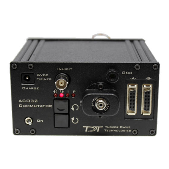
ACO32/ACO64 Motorized Commutators Overview The ACO32 and ACO64 (Active Commutator with Optogenetic stimulation) are motorized commutators that actively track rotation on a headstage cable connected to an awake, behaving subject. They spin the motor to compensate, eliminating turn-induced torque at the subject's end of the cable. -
Page 5: Power And Interface
FORJ - Fiber Optic Rotary Joint and Fiber Optic Cable Power and Interface The ACO32 has a rechargeable 1950 mAh Li-ion Battery. The ACO64 has a 3900 mAh battery. A 6-9 V, 3A, center negative adapter (one provided) charges the device. Low battery status is reported only by a decrease in rotational speed. -
Page 6: Aco64 Hardware Setup
ACO32/ACO64 Motorized Commutators | 6 Note The motor in the ACO32 commutator is attached to a plate designed to allow it to be disengaged for testing and troubleshooting noise issues. The plate may slide out of normal position during shipping or anytime the commutator is turned upside down. -
Page 7: Features
When contact is made, a ground loop is formed that temporarily adds extra noise to the system. Grounding this metal surface directly to the TDT hardware removes this ground loop at the cost of raising the overall noise floor a small amount. -
Page 8: Headstage Connections
Two or four interface receptacles are positioned on the rotary interface module. The receptacles are labeled to correspond to the DB26 connectors on the face. The ACO32 uses 'A' and 'B' labels, the ACO64 uses 1 to 4 silver marks on the receptacles. TDT offers headstages... -
Page 9: Amplifier Connections
ACO32/ACO64 Motorized Commutators | 9 The diagram above shows the ACO32 connection for the A subset of channels: • from headstage (with SPL16 analog or SPL16-D digital connectors) • to splice-to-splice connector • to commutator receptacle • to amplifier connection cable. - Page 10 Carefully pull the FORJ away from the commutator face until the fiber is free. Disconnect the fiber from the joint. Replace the fiber. To install the FORJ: Insert metal cannula end of fiber into center of gear inside of ACO32.
- Page 11 ACO32/ACO64 Motorized Commutators | 11 Slowly push fiber through hole until the end appears among the wires on the other side of the ACO32. Using a pair of tweezers, carefully pull the end of the fiber and insert it into the hole next to the encoder.
- Page 12 Connect the FC/PC connector end of the fiber to (the smaller section of) the fiber optic rotary joint. Slowly pull all of the excess fiber through the ACO32 until the FC/PC connector is inside the ACO32 and the fiber optic rotary joint plate can be attached to the ACO32 plate.
-
Page 13: Change Kits
If you purchased the ACO32 or ACO64 without a FORJ and then add one, use the kit below to mount the new optics to the ACO32 or ACO64 faceplate. If you purchased the ACO32 or ACO64 with a FORJ and wish to remove it, use the kit below to cover the opening where the FORJ was previously mounted. -
Page 14: Replacing The Optical Fiber (Aco64)
ACO32/ACO64 Motorized Commutators | 14 Note The two configurations use different screws, so be sure to save all screws. Replacing the Optical Fiber (ACO64) The FORJ assembly can be removed and re-installed by the user to replace the optical fiber. - Page 15 ACO32/ACO64 Motorized Commutators | 15 Disconnect the fiber from the joint. Replace the fiber. To install one optical fiber in the FORJ: Insert metal cannula end of the fiber into center of gear inside the ACO64. Slowly push fiber through hole until the end appears among the wires on the other side of the ACO64.
- Page 16 ACO32/ACO64 Motorized Commutators | 16 Secure the two encoder clamping shells back onto the ACO64 shaft by inserting and tightening the two screws. The plate should be just below the body of the ACO64 and the encoder body should sit snugly inside the lip of the clamping plates.
-
Page 17: Aco Technical Specifications
ACO32/ACO64 Motorized Commutators | 17 ACO Technical Specifications Channels ACO32 with analog PZ5 or PZA: up to 32 analog channels ACO32 with digital PZ5 or PZD: up to 256 digital channels ACO64 with analog PZ5 or PZA: up to 64 analog channels... -
Page 18: Aco32 Dimensions
ACO32/ACO64 Motorized Commutators | 18 ACO32 Dimensions... -
Page 19: Aco64 Dimensions
ACO32/ACO64 Motorized Commutators | 19 ACO64 Dimensions Interface Receptacles The interface receptacle diagram shows how the pins on each receptacle map to the pins on the associated DB26 connector on the face of the commutator. See pinouts below for the... -
Page 20: Aco32 And Aco64 Amplifier Connector Pinout
For information on making custom connections to the commutator, see Tech Note TN0896. ACO32 and ACO64 Amplifier Connector Pinout Connectors are labeled A and B on ACO32 and A, B, C, D on ACO64. Electrode channels below are relative to the electrode/headstage connected to the corresponding interface receptacle. - Page 21 When mapping channel numbers for recording purposes, the preamplifier connections must be taken into account. The first channel as labeled above is relative to the amplifier bank of channel numbers connected. If connector 'B' on the ACO32 is connected to Bank B on the preamplifier, E1 is channel 17. Important When using digital headstages and a PZ5 or PZD, channel mapping is handled by the PZ5 or PZD and channels will be ordered consecutively beginning with Connector 'A' on the commutator.
Need help?
Do you have a question about the ACO32 and is the answer not in the manual?
Questions and answers