TDT PZ5 Hardware Reference Manual
Neurodigitizer
Hide thumbs
Also See for PZ5:
- Manual (736 pages) ,
- Quick set-up manual and fast facts manual (2 pages)
Table of Contents
Advertisement
Quick Links
Advertisement
Table of Contents

Related Manuals for TDT PZ5


Summary of Contents for TDT PZ5
- Page 1 PZ5 NeuroDigitizer Hardware Reference Updated 2021-04-19...
- Page 2 The information contained in this document is provided "as is," and is subject to being changed, without notice. TDT shall not be liable for errors or damages in connection with the furnishing, use, or performance of this document or of any information contained herein.
-
Page 3: Table Of Contents
Physical Amplifier Logical Amplifiers Analog Recording Reference Modes Sampling Rate and Onboard Filters Sampling Rate and Digital Input Channels Amp Type Presets PZ5 Software Control Recording 128 Channels at 50 kHz PZ5 Touchscreen Impedance Checking Screen Waveform Display Screen Manual Configuration... -
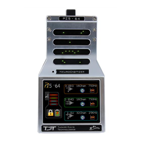
Page 4: Pz5 Neurodigitizer
The PZ5 is available in 32, 64, 96, or 128 analog channel models. The PZ5 is also available with 2 or 4 digital inputs and models that combine 32 or 64 analog input channels with 2 or 4 digital... -
Page 5: System Hardware
PZ5 NeuroDigitizer | 5 inputs. The PZ5 can support a total of up to 128 analog channels or up to 256 digital channels or up to 256 mixed channel types. The total number of channels is generally reduced to 128 at higher sampling rates, up to 50kHz. -
Page 6: Hardware Setup
To avoid introducing EMF noise, DO NOT connect the charger to the PZ5 while collecting data. A 5-meter paired fiber optic cable is included to connect the PZ5 to the base station. The connectors are color coded and keyed to ensure proper connections. -
Page 7: Connecting Headstages And Electrodes
Diagrams. Digital signals are input via Intan connectors on the PZ5 back panel. Powering ON/OFF To turn the PZ5 on, move the toggle switch located on the back panel of the PZ5 to the ON position. Physical Amplifier All PZ5 analog input channels are organized into groups of 16 channel banks, with each bank corresponding to a rear panel headstage connector (labeled alphabetically from bottom to top) and a front panel LED display. -
Page 8: Logical Amplifiers
Reference Modes for analog input banks. Two Possible Logical Amplifier Configurations for a PZ5-0-64 64 Channel (all analog input) Digital boards can be configured individually or grouped to share a single ground and use common filter settings and sampling rate. -
Page 9: Analog Recording Reference Modes
Logical amplifier configurations can be defined using the front panel interface (see Touchscreen), in Synapse, or in RPvdsEx using the PZ5_Control macro. The PZ5-0-32 model can have a maximum of two logical amplifiers configured. All other PZ5s can have a maximum of four logical amplifiers. -
Page 10: Sampling Rate And Onboard Filters
At 50 kHz the native channel numbers per board are 1-20 and 33-52. These channel numbers are then offset by the number of channels existing in the lower banks of the PZ5. Also see Input Connectors. -
Page 11: Amp Type Presets
Referencing: Local Coupling: AC Sample Rate: 25kHz The PZ5 touchscreen interface uses representative diagrams to enable users to identify the configuration of the amplifier at a glance. The table below explains the parts of the diagram and what each represents. -
Page 12: Pz5 Software Control
PZ5 NeuroDigitizer | 12 PZ5 Signal/Reference Diagram PZ5 Software Control All PZ5 configuration and control of data acquisition is managed through Synapse. The PZ5 object configures the analog and digital headstage recording inputs. Please see the Synapse Manual for more information. -
Page 13: Recording 128 Channels At 50 Khz
PZ5 NeuroDigitizer | 13 Recording 128 Channels at 50 kHz Due to the PZ5's high bit resolution and recording capabilities, data should always be stored as 32-bit floating point. However, when storing 128 channels at 50 kHz sampling rate, you must use the Short (16 bits) format due to bandwidth constraints. -
Page 14: Impedance Checking Screen
Impedance Checking Screen Important The impedance checking feature of the PZ5 can and should only be used with a passive headstage or direct connection to the electrodes. Enter the Impedance Checking screen by touching this icon on an existing logical amplifier on the Main Configuration screen. - Page 15 Set the probe signal frequency from a drop down list. The frequency is adjustable from 35 Hz, 70 Hz, 140 Hz, 280 Hz, 560 Hz, 1120 Hz, and 2240 Hz. This feature is only selectable in daughter board firmware v1.3 and above, and PZ5 software v1.1.1 and above. The frequency is fixed at 140 Hz in prior versions.
-
Page 16: Waveform Display Screen
PZ5 NeuroDigitizer | 16 Waveform Display Screen Enter the Waveform Display screen by touching this icon on an existing logical amplifier on the Main Configuration Option screen. The displayed waveform is decimated for plotting and high pass filtered so all channels can be shown on the same voltage scale. -
Page 17: Manual Configuration
To return to the Main Configuration screen, swipe three fingers across the screen in any direction. Manual Configuration The logical amplifier configuration defined in Synapse is sent to the PZ5 and applied when the recording begins. However, the touchscreen interface can also be used to configure logical amplifiers on-the-fly. -
Page 18: Configuration Options Screen
Ext. Ground Press 'More' button to access this. Set to Yes to connect this logical amplifier ground to the external ground plug on the physical PZ5 device. Caution: When using multiple sub-amps make sure they aren't all sharing the External Ground... -
Page 19: Battery Status
Level % battery life remaining. Endurance Estimated time of battery life remaining Note The Battery Level is also mirrored on the RZ2 LCD display when the PZ5 is connected to the PZ Amplifier port on the back of the RZ2. -
Page 20: System Setup Screen
PZ5 NeuroDigitizer | 20 System Setup Screen The System Setup screen is displayed by touching the PZ5 logo on the top-left of the Main Configuration screen. Button Description Config Open the System Configure screen Update Update onboard software over the Internet... -
Page 21: System Info Screen
Does not overwrite any existing logical amplifier configuration on boot. For example, if you configure the logical amplifiers in Synapse before the PZ5 boots then the PZ5 will NOT overwrite that configuration. If the PZ5 boots and NO logical amplifiers are configured it will behave the same as Last. -
Page 22: System Update Screen
The System Update screen is displayed by touching Update on the System Setup screen. Important The update process can take up to an hour to complete. Make sure the PZ5 battery charger is plugged in during the update. Wireless Networks Screen The Wireless Networks screen is displayed by touching WiFi on the System Setup screen. -
Page 23: Pz5 Features
Green: Activity Red: Clip Warning Note The LED indicators are also mirrored on the RZ2 LCD display when the PZ5 is connected to the PZ Amplifier port on the back of the RZ2. Clip Warning Analog clipping occurs when the input signal is too large. When the input to a channel is within 3 dB of the PZ5's maximum voltage input range the LED for the corresponding channel is lit red to indicate that clipping may occur. -
Page 24: External Ground
A banana jack located on the back of the PZ5 provides connection to common ground. Any logical amplifier configured through the PZ5 touchscreen has this shorted by default. The PZ5 gizmo in Synapse allow you to float that ground connection on individual sub-amplifiers. -
Page 25: Charging The Batteries
PZ5 NeuroDigitizer | 25 Charging the Batteries Operate the PZ5 with the charging cable disconnected. An external battery pack (PZ-BAT) or external charger and extra battery (PZ5-BAT) is available for longer battery life and extended recording sessions. See PZ-BAT and PZ5-BAT. -
Page 26: Digital Inputs
750 Hz Digital Inputs RHD2000 series amplifier boards and SPI interface cables are available from Intan Technologies. They are also used in TDT's ZD and OD Intan-based Digitizing headstages. Important The specifications below are dependent on the amplifier board. See... -
Page 27: General
100 Mbps Input Connectors The PZ5 has up to eight 26-pin headstage connectors (analog) or up to four 12-pin Omnetics nano connectors (digital) on the back of the unit. The connectors are labeled alphabetically from bottom to top. Each connector carries signal for one bank of channels with ground and reference. -
Page 28: Pinout Diagrams
PZ5 NeuroDigitizer | 28 Pinout Diagrams Local, None or Shared Reference Mode Name Description Name Description Analog Input Channels Positive Voltage (+2.5V) Ground Ground Negative Voltage (-2.5V) Ref* Reference* Headstage Detect Headstage Detect Analog Input Channels Analog Input Channels See notes below... - Page 29 PZ5 NeuroDigitizer | 29 Note There are 8 (+) channels and 8 (-) channels per DB26 connector. Subsequent banks are indexed by an additional 8 channels. Name Description Name Description A1(+) Analog Input Channel Positive Voltage (+2.5V) A1(-) Differential Analog Input Channel...
Need help?
Do you have a question about the PZ5 and is the answer not in the manual?
Questions and answers