Table of Contents
Advertisement
Quick Links
Advertisement
Table of Contents

Related Manuals for TDT RZ6


Summary of Contents for TDT RZ6
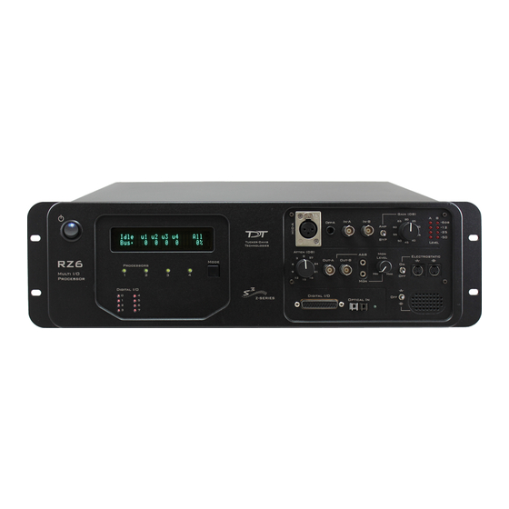
- Page 1 RZ6 Multi I/O Processor Hardware Reference Updated 2021-09-15...
- Page 2 The information contained in this document is provided "as is," and is subject to being changed, without notice. TDT shall not be liable for errors or damages in connection with the furnishing, use, or performance of this document or of any information contained herein.
-
Page 3: Table Of Contents
Table of Contents | 3 Table of Contents RZ6 Multi I/O Processor RZ6 Overview Power and Communication Software Control RZ6 Architecture Bus Related Delays Functional Signal Flow Diagrams RZ6 Features DSP Status Lights Front Panel Display Screen Onboard Analog I/O and Optional Amplifier Input... -
Page 4: Rz6 Multi I/O Processor
Sharc DSP; quad-core processor cards use four Sharc DSPs cores with the potential to more than double the power of the RZ6. All cards are networked on a multiprocessor architecture that features efficient onboard communication and memory access. -
Page 5: Power And Communication
RZ2 to the PC. Connectors on the back panel are color coded for correct wiring. The RZ6's integrated power supply is shipped from TDT configured for the end user's regional voltage setting (110 V or 220 V). If you need to change the voltage setting:... -
Page 6: Software Control
TDT's Synapse BioSigRZ software controls the RZ6 and provides users a high level interface for device configuration. If using RPvdsEx to design circuits for the RZ6, see the Legacy System 3 Manual for information on what macros to use. RZ6 Architecture The RZ6 processor uses a multi-bus architecture and offers three dedicated, data buses for fast, efficient data handling. -
Page 7: Bus Related Delays
RZ6 Multi I/O Processor | 7 As shown in the diagram above, the RZ6 architecture consists of three functional blocks: The DSPs Each DSP in the DSP Block is connected to a local interface to the three data buses: two buses that connect each DSP to the other functional blocks and one that handles data transfer between the DSPs. - Page 8 RZ6 Multi I/O Processor | 8 RZ6 Analog Input Flow Diagram Input signals for channel A are input either through the XLR input (Mic-A), the audio jack input (Diff-A), or BNC (In-A). Input signals for channel B are input through the BNC (In-B).
-
Page 9: Rz6 Features
RZ6 Multi I/O Processor | 9 Finally, if the electrostatic speaker driver is enabled via its switch, located on the front panel, signals A and B are output from the mini-DIN ports located on the RZ6 front panel. RZ6 Features... -
Page 10: Onboard Analog I/O And Optional Amplifier Input
Note: Eight solid bars denote that the signal on ADC A or B is clipping. Onboard Analog I/O and Optional Amplifier Input The RZ6 is equipped with onboard analog I/O and attenuators. It may also include a fiber optic port for Medusa preamplifier input. -
Page 11: A And B Microphone Amplifier
RZ6 Multi I/O Processor | 11 Channel B uses only the BNC labeled In-B: Important Use only one input for channel A at a time. Attempting to input signals from multiple sources will produce an erroneous signal. A and B Microphone Amplifier An onboard two channel amplifier provides gain for the onboard analog input signals (MIC-A, DIFF-A, In-A, and In-B). -
Page 12: Fiber Optic Port - Optional
RZ6 can oversample the digitized signals up to 8X or ~200 kHz. This will allow the RZ6 to run a DSP chain at ~200 kHz and still sample data acquired through an optically connected preamplifier. -
Page 13: Manual Attenuator
These outputs use a stereo power amplifier to drive TDT's MF1 multi-function speakers. A single signal generated or input from any of the RZ6 analog inputs can be ganged to reduce the spectral variation in power of the transducer across all frequencies. -
Page 14: Monitor Speaker
Note All outputs use stereo power amplifiers Monitor Speaker The RZ6 is equipped with an onboard monitor speaker, provided for audio monitoring of a single channel. A switch located directly to the left of the monitor speaker is used to select between DAC channels A and B or to disable the monitor speaker. -
Page 15: Digital I/O
(A, B, and C) as described in the chart below. All digital I/O lines are accessed via the 25- pin connector on the front of the RZ6. Earlier versions (serial number < 2000) were limited to 8 bits. See RZ6 Technical Specifications for the DB25 pinout. -
Page 16: Led Indicators
Bit is configured for input and is currently a logical high (1) Analog Input - ADC LED Indicators The ADC LED indicators are labeled and located at the top right of the RZ6 front panel. The LEDs indicate the level of the signals on ADC channels A and B. -
Page 17: Rz6 Technical Specifications
Medusa preamplifier is correctly synced with the RZ6. RZ6 Technical Specifications Note The RZ6 can be equipped with a fiber optic input port and used with a four channel Medusa preamplifier. See the preamplifier's technical specifications for A/D converters. Up to four standard DSPs and/or quad-core (QZDSP) DSP: 400 MHz DSPs, 2.4 GFLOPS peak per DSP... - Page 18 RZ6 Multi I/O Processor | 18 2 channels, 24-bit sigma-delta Sample Rate Up to 195312.50 Hz Frequency Response DC - 0.44*Fs (Fs = sample rate) Voltage In ± 10.0 V S/N (typical) 115 dB (20 Hz - 80 kHz at 5 V RMS)
-
Page 19: D/A Db Rolloff Diagram
For further information on speaker specifications, see ES1/EC1 Technical Specifications MF1 Technical Specifications. D/A dB Rolloff Diagram This graph shows the dB rolloff for the RZ6 with varying sampling frequencies for the D/A. The sample delay remains constant for varying frequencies. DB25 Digital I/O Pinout... - Page 20 RZ6 Multi I/O Processor | 20 Name Description Name Description Port C Bit Addressable Port C Bit Addressable Digital I/O Ground Port A Word Addressable Port A Word Addressable Port B Word Addressable Port B Word Addressable If using a PP24 Patch Panel, see PP24 to RZ6 Digital I/O.
Need help?
Do you have a question about the RZ6 and is the answer not in the manual?
Questions and answers