Advertisement
Quick Links
Fast Facts
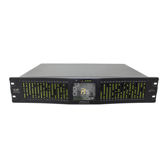
The PZ5M NeuroDigitizer
This fast fact sheet provides basic information for the PZ5M. See the
System 3 Manual for more information.
LED Channel Indicators
Hardware Setup. Use the provided paired fiber optic
cable to connect the PZ5M to the RZ processor, as
shown below. The connectors are color coded and
keyed to ensure proper connections. The PZ5M-512 is
shown below. If using the PZ5M-256, connect only to
the primary connection on the RZ2 (located adjacent to
the zBUS connection).
PZ Input
Software Configuration. Logical amplifiers can be
configured on the Synapse, PZ5 options page. The table
below lists default settings for each analog input amp
type.
The table below lists default settings for each amp type.
Referencing
EMG
Diff (true differential) AC
EEG
Shared
LFP
Shared
SU
Local
Power Status LEDs
Touch Screen
DSP-P
Coupling
Sample Rate
750 Hz
AC
750 Hz
AC
3 kHz
AC
25 kHz
Using the Front Panel Display. The front panel touch
screen display (icons shown below) can be used for
impedance testing, waveform preview, and on-the-fly
device configuration.
Open System Setup screen to access wifi
and device information.
Lock/Unlock configuration settings.
Create a new logical amplifier. If all banks
are configured, the green plus sign is not
displayed.
Toggle LED indicators off/on.
Touch the icon in the logical amp
configuration
Amp
Configuration
to display the desired screen for the
corresponding logical amplifier.
Caution: Touch screen logical amp
Test
Impedance
configuration settings are overwritten at
run time when using the PZ5M_Control
macro.
Preview
Waveform
Banks are color coded to indicate current
configuration.
Configuration
EMG
EEG
LFP
SU
Not configured
Warning. A red outline indicates that the bank is
configured as part of a logical amplifier but no headstage
is currently detected on that bank.
area
(shown
Color Codes
Green
Brown
Purple
Teal
Gray
below)
Advertisement

Related Manuals for TDT synapse PZ5M NeuroDigitizer


Summary of Contents for TDT synapse PZ5M NeuroDigitizer
- Page 1 Fast Facts The PZ5M NeuroDigitizer This fast fact sheet provides basic information for the PZ5M. See the System 3 Manual for more information. Using the Front Panel Display. The front panel touch screen display (icons shown below) can be used for Power Status LEDs impedance testing, waveform preview, and on-the-fly device configuration.
- Page 2 None: Input the input channels Sort. Display channels with the largest variation from the target impedance at the top of the screen. Auto. Cycle through probing options each second. support@tdt.com Next. Advance to the next probing option set. www.tdt.com...
Need help?
Do you have a question about the synapse PZ5M NeuroDigitizer and is the answer not in the manual?
Questions and answers