Table of Contents
Advertisement
Quick Links
-7-Series AC Servo Drive
7C
-
SERVOPACK
Product Manual
Model: SGD7C-AMAA
MANUAL NO. SIEP S800002 04B
Basic Information on
SERVOPACKs
Installation
Wiring and Connections
Preparations
Device-Specific Settings
Trial Operation
Creating User Programs
Tuning
Monitoring
Maintenance
Parameter Lists
Functions of the
Controller Section
1
2
3
4
5
6
7
8
9
10
11
12
Advertisement
Table of Contents
Troubleshooting

Subscribe to Our Youtube Channel
Related Manuals for YASKAWA SGD7C-***AMAA***


Summary of Contents for YASKAWA SGD7C-***AMAA***
- Page 1 -7-Series AC Servo Drive SERVOPACK Product Manual Model: SGD7C-AMAA Basic Information on SERVOPACKs Installation Wiring and Connections Preparations Device-Specific Settings Trial Operation Creating User Programs Tuning Monitoring Maintenance Parameter Lists Functions of the Controller Section MANUAL NO. SIEP S800002 04B...
- Page 2 Yaskawa. No patent liability is assumed with respect to the use of the informa- tion contained herein. Moreover, because Yaskawa is constantly striving to improve its high-quality products, the information contained in this manual is sub- ject to change without notice.
- Page 3 About this Manual This manual provides information required to select Σ-7C SERVOPACKs for Σ-7-Series AC Servo Drives, and to design, perform trial operation of, tune, operate, and maintain the Servo Drives. Read this manual carefully to ensure the correct usage of Σ-7-Series AC Servo Drives. Keep this manual in a safe place so that it can be referred to whenever necessary.
- Page 4 Related Documents The relationships between the documents that are related to the Servo Drives are shown in the fol- lowing figure. The numbers in the figure correspond to the numbers in the table on the following pages. Refer to these documents as required. y tem Component Machine Controller...
- Page 5 Classification Document Name Document No. Description Describes the features and applica- Machine Controller and tion examples for combinations of Machine Controller and AC Servo Drive KAEP S800001 22 MP3000-Series Machine Control- Servo Drive Σ Solutions Catalog lers and -7-Series AC Servo General Catalog Drives.
- Page 6 Continued from previous page. Classification Document Name Document No. Description Σ -7-Series AC Servo Drive Provides detailed information for Σ Σ Σ -7S and -7W SERVOPACK TOMP C710828 00 the safe usage of -7-Series Safety Precautions SERVOPACKs. Σ Σ -V-Series/ -V-Series for Large-Capacity Models/ Provides detailed information for...
- Page 7 Continued from previous page. Classification Document Name Document No. Description Σ -7-Series AC Servo Drive Σ -7S SERVOPACK with SIEP S800001 28 MECHATROLINK-III Communications References Product Manual Σ -7-Series AC Servo Drive Σ -7S SERVOPACK with SIEP S800001 27 MECHATROLINK-II Communications References Product Manual Σ...
- Page 8 Continued from previous page. Classification Document Name Document No. Description Σ -7-Series AC Servo Drive Σ -7S SERVOPACK with SIEP S800001 84 FT/EX Specification for Index- ing Application Product Manual Σ -7-Series AC Servo Drive Σ -7S SERVOPACK with SIEP S800001 89 FT/EX Specification for Track- ing Application Product Manual...
- Page 9 Continued from previous page. Classification Document Name Document No. Description Σ -7-Series AC Servo Drive SIEP S800001 36 Rotary Servomotor Product Manual Σ Provide detailed information on -7-Series AC Servo Drive Σ -7-Series SIEP S800001 37 selecting, installing, and connecting Linear Servomotor Servomotor Σ...
- Page 10 Continued from previous page. Classification Document Name Document No. Description Machine Controller MP2000/MP3000 Series Describes in detail how to operate Engineering Tool SIEP C880761 03 MPE720 version 7. MPE720 Version 7 User’s Manual Σ Describes the operating proce- -7-Series AC Servo Drive Σ...
- Page 11 Using this Manual Technical Terms Used in This Manual The following terms are used in this manual. Term Meaning Α Σ-7-Series Rotary Servomotor, Direct Drive Servomotor, or Linear Servomotor. Servomotor A generic term used for a Σ-7-Series Rotary Servomotor (SGMMV, SGM7J, SGM7A, SGM7P, Rotary Servomotor or SGM7G) or a Direct Drive Servomotor (SGM7E, SGM7F, SGMCV or SGMCS).
- Page 12 Notation Used in this Manual Notation for Reverse Signals The names of reverse signals (i.e., ones that are valid when low) are written with a forward slash (/) before the signal abbreviation. Notation Example BK is written as /BK. ...
- Page 13 Notation Example Notation Example for Pn002 Digit Notation Numeric Value Notation n . 0 0 0 0 Notation Meaning Notation Meaning Pn002 = Pn002 = Indicate the fir t digit from Indicate that the fir t digit from the right in Pn002. the right in Pn002 i et to 1.
- Page 14 Safety Precautions Safety Information To prevent personal injury and equipment damage in advance, the following signal words are used to indicate safety precautions in this document. The signal words are used to classify the hazards and the degree of damage or injury that may occur if a product is used incorrectly. Information marked as shown below is important for safety.
- Page 15 Safety Precautions That Must Always Be Observed General Precautions DANGER Read and understand this manual to ensure the safe usage of the SERVOPACK. Keep this manual in a safe, convenient place so that it can be referred to whenever necessary. Make sure that it is delivered to the final user of the SERVOPACK.
- Page 16 NOTICE Do not attempt to use a SERVOPACK or Servomotor that is damaged or that has missing parts. Install external emergency stop circuits that shut OFF the power supply and stop operation immediately when an error occurs. In locations with poor power supply conditions, install the necessary protective devices (such as AC reactors) to ensure that the input power is supplied within the specified voltage range.
- Page 17 NOTICE Do not hold onto the front cover or connectors when you move a SERVOPACK. There is a risk of the SERVOPACK falling. The SERVOPACK or Servomotor is a precision device. Do not drop it or subject it to strong shock.
- Page 18 NOTICE Do not install or store the SERVOPACK in any of the following locations. • Locations that are subject to direct sunlight • Locations that are subject to ambient temperatures that exceed SERVOPACK specifications • Locations that are subject to relative humidities that exceed SERVOPACK specifications •...
- Page 19 CAUTION Wait for at least six minutes after turning OFF the power supply and then make sure that the CHARGE indicator is not lit before starting wiring or inspection work. Do not touch the power supply terminals while the CHARGE lamp is lit because high voltage may still remain in the SER- VOPACK even after turning OFF the power supply.
- Page 20 Whenever possible, use the Cables specified by Yaskawa. If you use any other cables, confirm the rated current and application environment of your model and use the wiring materials specified by Yaskawa or equivalent materials. Securely tighten cable connector lock screws and lock mechanisms.
- Page 21 Operation Precautions WARNING Before starting operation with a machine connected, change the settings of the switches and parameters to match the machine. Unexpected machine operation, failure, or personal injury may occur if operation is started before appropriate settings are made. ...
- Page 22 CAUTION Design the system to ensure safety even when problems, such as signal line disconnection, occur. For example, the P-OT and N-OT signals are set in the default settings to operate on the safe side if there is a signal line disconnection. Do not change the polarity of this type of signal. ...
- Page 23 CAUTION Always check to confirm the paths of axes when any of the following axis movement instruc- tions are used in programs to ensure that the system operates safely. • Positioning (MOV) • Linear Interpolation (MVS) • Circular Interpolation (MCC or MCW) •...
- Page 24 CAUTION The Move on Machine Coordinates (MVM) instruction temporarily performs positioning to a coordinate position in the machine coordinate system. Therefore, unexpected operation may occur if the instruction is executed without confirming the origin position in the machine coordi- nate system first.
- Page 25 NOTICE Discharge all static electricity from your body before you operate any of the buttons or switches inside the front cover of the SERVOPACK. There is a risk of equipment damage. Troubleshooting Precautions DANGER If the safety device (molded-case circuit breaker or fuse) installed in the power supply line oper- ates, remove the cause before you supply power to the SERVOPACK again.
- Page 26 We will update the manual number of the manual and issue revisions when changes are made. Any and all quality guarantees provided by Yaskawa are null and void if the customer modifies the SERVOPACK in any way. Yaskawa disavows any responsibility for damages or losses that are caused by modified SERVOPACKs.
- Page 27 • Events for which Yaskawa is not responsible, such as natural or human-made disasters Limitations of Liability • Yaskawa shall in no event be responsible for any damage or loss of opportunity to the customer that arises due to failure of the delivered product.
- Page 28 • It is the customer’s responsibility to confirm conformity with any standards, codes, or regulations that apply if the Yaskawa product is used in combination with any other products. • The customer must confirm that the Yaskawa product is suitable for the systems, machines, and equipment used by the customer.
- Page 29 Compliance with UL Standards and EU Directives Certification marks for the standards for which the product has been certified by certification bod- ies are shown on the nameplate. Products that do not have the marks are not certified for the stan- dards.
- Page 30 European Directives Product Model EU Directive Harmonized Standards Machinery Directive EN ISO13849-1: 2015 2006/42/EC EN 55011 group 1, class A EN 61000-6-2 EMC Directive EN 61000-6-4 2014/30/EU EN 61800-3 (Category C2, SERVOPACKs SGD7C Second environment) Low Voltage Directive EN 50178 2014/35/EU EN 61800-5-1 RoHS Directive...
-
Page 31: Table Of Contents
Contents About this Manual..........iii Outline of Manual . - Page 32 1.13 Functions ......... 1-42 1.13.1 Servo Section Functions.
- Page 33 Servo Section I/O Signal Connections ....3-34 3.6.1 I/O Signal Connector (CN1) Names and Functions ....3-34 3.6.2 I/O Signal Connector (CN1) Pin Layout .
- Page 34 Precautions When Setting the Parameters ....5-12 5.2.1 Precautions When Setting Circuit Numbers ......5-12 5.2.2 Precautions When Setting Module Configuration Definitions .
- Page 35 5.17 Setting the Origin of the Absolute Encoder ....5-46 5.17.1 Absolute Encoder Origin Offset ....... . . 5-46 5.17.2 Setting the Origin of the Absolute Linear Encoder .
- Page 36 Trial Operation Flow of Trial Operation ....... . 6-2 6.1.1 Flow of Trial Operation for Rotary Servomotors .
- Page 37 Debugging Ladder Programs ......7-56 7.6.1 Ladder Program Runtime Monitoring ......7-56 7.6.2 Register List Panes .
- Page 38 Estimating the Moment of Inertia ..... . . 8-16 8.5.1 Outline ........... .8-16 8.5.2 Restrictions .
- Page 39 8.13 Manual Tuning ........8-73 8.13.1 Tuning the Servo Gains .
- Page 40 Functions of the Controller Section 12.1 Data Logging ........12-3 12.1.1 Operating Procedure .
- Page 41 Basic Information on SERVOPACKs This chapter provides an overview of the SERVOPACKs and gives the SERVOPACK specifications. The Σ-7-Series Σ-7C SERVOPACKs ..1-3 Part Names ......1-5 Interpreting the Nameplate .
- Page 42 Interpreting the Displays and Indicators . . 1-30 1.8.1 Servo Section ......1-30 1.8.2 Controller Section ..... . .1-32 Interpreting Switch Labels .
-
Page 43: The Σ-7-Series Σ-7C Servopacks
1.1 The Σ-7-Series Σ-7C SERVOPACKs The Σ-7-Series Σ-7C SERVOPACKs The Σ-7-Series SERVOPACKs are designed for applications that require frequent high-speed and high-precision positioning. The SERVOPACK will make the most of machine performance in the shortest time possible, thus contributing to improving productivity. The following three types of Σ-7-Series SERVOPACKs are available. - Page 44 1.1 The Σ-7-Series Σ-7C SERVOPACKs Easier Maintenance • The battery-free Controller Section eliminates the need for regular battery replacement and reduces costs. • Protection has been improved for outputs from the Controller Section. A conceptual diagram of an Σ-7C SERVOPACK is provided below. Σ-7C ERVOPACK Controller ection ervo ection...
-
Page 45: Part Names
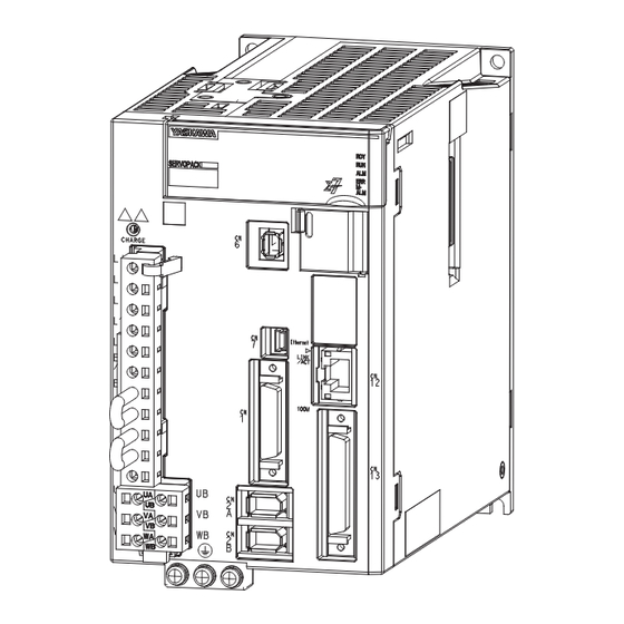
1.2 Part Names Part Names ERVOPACK with the Front Cover Open Main circuit terminal 17 17 20 20 (on ide of ERVOPACK) 21 21 18 18 19 19 22 22 11 11 With the Front Cover Open 12 12 24 24 14 14 15 15 25 25... - Page 46 1.2 Part Names Continued from previous page. Name Description Reference Servo Section Display for Axis A Displays the servo status with a seven-segment display. page 1-30 Servo Section Display for Axis B Controller Section Displays Show the execution or error status of the CPU. page 1-33 Controller Section Status Show the status of the CPU.
-
Page 47: Interpreting The Nameplate
1.3 Interpreting the Nameplate Interpreting the Nameplate The following basic information is provided on the nameplate. Protection cla ERVOPACK model urrounding air temperature BTO information Order number erial number... -
Page 48: Model Designations
1.4 Model Designations 1.4.1 Interpreting SERVOPACK Model Numbers Model Designations 1.4.1 Interpreting SERVOPACK Model Numbers GD7C - 1R6 1 t+2nd+ rd digit 5th+6th digit 8th+9th+10th digit 4th digit 7th digit Σ-7- erie Σ-7C ERVOPACK Maximum Applicable Interface * 1 t+2nd+ rd digit 5th+6th digit Motor Capacity per Axi pecification... -
Page 49: Interpreting Servomotor Model Numbers
1.4 Model Designations 1.4.2 Interpreting Servomotor Model Numbers 1.4.2 Interpreting Servomotor Model Numbers This section outlines the model numbers of Σ-7-Series Servomotors. Refer to the following manuals for details. Σ-7-Series Rotary Servomotor Product Manual (Manual No.: SIEP S800001 36) Σ-7-Series Linear Servomotor Product Manual (Manual No.: SIEP S800001 37) Σ-7-Series Direct Drive Servomotor Product Manual (Manual No.: SIEP S800001 38) Rotary Servomotors - 01... - Page 50 1.4 Model Designations 1.4.2 Interpreting Servomotor Model Numbers Linear Servomotors 0 A 050 C P 1 t digit 2nd digit rd digit on erie Σ-7- erie erie ervomotor 2nd digit Moving Coil/Magnetic Way Code pecification 1 t digit ervomotor Type Moving Coil pecification...
-
Page 51: Ratings And Specifications
1.5 Ratings and Specifications 1.5.1 Ratings Ratings and Specifications This section gives the ratings and specifications of SERVOPACKs. 1.5.1 Ratings Three-Phase, 200 VAC SGD7C- 1R6A 2R8A 5R5A 7R6A Maximum Applicable Motor Capacity per Axis [kW] 0.75 Continuous Output Current per Axis [Arms] Instantaneous Maximum Output Current per Axis [Arms] 16.9 17.0... -
Page 52: Servopack Overload Protection Characteristics
Note: The above overload protection characteristics do not mean that you can perform continuous duty operation with an output of 100% or higher. For a Yaskawa-specified combination of SERVOPACK and Servomotor, maintain the effective torque within the continuous duty zone of the torque-motor speed characteristic of the Servomotor. -
Page 53: General Specifications
Note: The above overload protection characteristics do not mean that you can perform continuous duty operation with an output of 100% or higher. For a Yaskawa-specified combination of SERVOPACK and Servomotor, maintain the effective torque within the continuous duty zone of the torque-motor speed characteristic of the Servomotor. -
Page 54: Servo Section Specifications
1.5 Ratings and Specifications 1.5.4 Servo Section Specifications 1.5.4 Servo Section Specifications Item Specification 1:5000 (At the rated torque, the lower limit of the speed control range Speed Control Range must not cause the Servomotor to stop.) ±0.01% of rated speed max. (for a load fluctuation of 0% to 100%) 0% of rated speed max. -
Page 55: Controller Section Specifications
1.5 Ratings and Specifications 1.5.5 Controller Section Specifications Continued from previous page. Item Specification Overcurrent, overvoltage, undervoltage, overload, regeneration error, Protective Functions etc. Utility Functions Gain adjustment, alarm history, jogging, origin search, etc. Applicable Option Modules None The coefficient of speed fluctuation for load fluctuation is defined as follows: No-load motor peed −... - Page 56 1.5 Ratings and Specifications 1.5.5 Controller Section Specifications Continued from previous page. Item Specification Remarks 0.5 ms to 32.0 ms Refer to the following section for details. H Scan (in 0.25-ms incre- 4.3.5 Setting the Scan Times on page 4- ments) 2.0 ms to 300 ms Scan Time...
- Page 57 1.5 Ratings and Specifications 1.5.5 Controller Section Specifications Continued from previous page. Item Specification Remarks − S Registers 64 Kwords − M Registers 1 Mword − G Registers 2 Mwords − I/O Registers 64 Kwords Registers − Motion Registers 32 Kwords −...
- Page 58 1.5 Ratings and Specifications 1.5.5 Controller Section Specifications Communications Function Module Specifications Item Specification Remarks Abbreviation 218IFD − Transmission Interface 10Base-T/100Base-TX Com- Number of Communications Ports (Con- − nectors) Items TCP/UDP/IP/ARP/ICMP/ − Transmission Protocols IGMP Maximum Number of Communications 20 + 2 (I/O message commu- −...
- Page 59 1.5 Ratings and Specifications 1.5.5 Controller Section Specifications Motion Control Function Module Specifications Module Item Specification Number of Controlled Axes Reference Update Cycle 500 μs to 32.0 ms (High-Speed Scan Cycle Per- formed by the CPU) Registers for two axes are assigned from the registers for each circuit.
- Page 60 1.5 Ratings and Specifications 1.5.5 Controller Section Specifications M-EXECUTOR Function Module Specifications Registerable Programs Program Type Number of Registered Programs Motion Programs Startup Interrupt Not possible. Sequence Programs H scan L scan The combined total of motion programs and sequence programs must not exceed 32. ...
- Page 61 − neously Open Files Formatting Not supported. Use a formatted USB memory device. Recommended USB Memory Device The following USB memory device is recommended. It can be purchased from Yaskawa. Model Specification Manufacturer SFU24096D1BP1TO-C-QT-111-CAP 4-GB USB memory Swissbit Japan Inc.
- Page 62 1.5 Ratings and Specifications 1.5.5 Controller Section Specifications Counter Function Module Specifications The following table gives the specifications of Counter Function Module. The Counter Function Module uses a pulse input on one channel. Item Specification Number of Inputs 1 (phase A, B, or Z input) Phases A and B: 5-V differential input, not isolated, maxi- mum frequency: 4 MHz Input Circuits...
- Page 63 1.5 Ratings and Specifications 1.5.5 Controller Section Specifications System Register Specifications This section shows the overall structure of the system registers. Register Contents Reference Addresses SW00000 to System Service Registers 12.10 System Service Registers on page 12-78 SW00029 SW00030 to System Status SW00049 SW00050 to...
- Page 64 1.5 Ratings and Specifications 1.5.5 Controller Section Specifications Continued from previous page. Register Contents Reference Addresses SW09216 to Reserved. SW09559 SW09560 to Expansion System I/O Error Status SW10627 SW10628 to Reserved. SW13699 SW13700 to Expanded Unit and Module Information SW14259 SW14260 to Reserved.
-
Page 65: Block Diagrams
1.6 Block Diagrams 1.6.1 SGD7C-1R6A and -2R8A Block Diagrams Internal block diagrams for the Servo Section are provided below. 1.6.1 SGD7C-1R6A and -2R8A ervomotor for axi A Vari tor Main circuit power − CHARGE upply Dynamic brake circuit Voltage Relay drive en or Dynamic brake circuit... -
Page 66: Sgd7C-5R5A And -7R6A
1.6 Block Diagrams 1.6.2 SGD7C-5R5A and -7R6A 1.6.2 SGD7C-5R5A and -7R6A ervomotor for axi A Vari tor Main circuit power − CHARGE upply Dynamic brake circuit Voltage Relay drive en or Dynamic brake circuit Gate drive Gate drive Voltage Current Current Temperature Gate drive... -
Page 67: External Dimensions
1.7 External Dimensions 1.7.1 Front Cover Dimensions and Connector Specifications External Dimensions 1.7.1 Front Cover Dimensions and Connector Specifications The front cover dimensions and panel connector section are the same for all models. Refer to the following figures and table. •... -
Page 68: Servopack External Dimensions
1.7 External Dimensions 1.7.2 SERVOPACK External Dimensions 1.7.2 SERVOPACK External Dimensions Base-Mounted SERVOPACKs • Three-phase, 200 VAC: SGD7C-1R6A and -2R8A 4 × M4 Exterior et of terminal 90 ±0.5 (26) 17 (mounting pitch) Ground terminal (76) (180) × M4 crew Mounting Hole Diagram Approx. - Page 69 1.7 External Dimensions 1.7.2 SERVOPACK External Dimensions Rack-Mounted SERVOPACKs Hardware Option Code: 001 • Three-phase, 200 VAC: SGD7C-1R6A and -2R8A 4 x M4 Exterior et of terminal 50 ±0.5 (mounting pitch) (26) 17 24.5 Ground terminal (76) Mounting Hole Diagram ×...
-
Page 70: Interpreting The Displays And Indicators
1.8 Interpreting the Displays and Indicators 1.8.1 Servo Section Interpreting the Displays and Indicators This section describes how to interpret the displays and the indicators on the SERVOPACK. 1.8.1 Servo Section Servo Section Indicators The indicators on the Servo Section give the status of the main circuit power supply and the control power supply. - Page 71 1.8 Interpreting the Displays and Indicators 1.8.1 Servo Section Color Display Description and Status Lit: The control power supply is ON. Status of the /TGON (Rotation Detection Output) Signal • Lit: The Servomotor speed is faster than the specified value. •...
-
Page 72: Controller Section
1.8 Interpreting the Displays and Indicators 1.8.2 Controller Section 1.8.2 Controller Section Controller Section Indicators There are three types of indicators on the Controller Section. Status Indicators These indicators show the status of the CPU. Indicator Color Status When Lit* Name Green Operation is normal. - Page 73 1.8 Interpreting the Displays and Indicators 1.8.2 Controller Section Ethernet Status Indicators These indicators show the status of Ethernet communications. Indicator Color Status When Not Lit, Lit, or Flashing Name Lit: Ethernet link established. LINK/ACT Yellow Flashing: Ethernet communications activity. Not lit: 10 M connection 100M Green...
-
Page 74: Interpreting Switch Labels
1.9 Interpreting Switch Labels Interpreting Switch Labels This section describes how to interpret the switch labels on the SERVOPACK. There are two types of switches in the Controller Section. DIP Switches: Mode Switches These switches are primarily used to set the operating mode of the CPU. Switch Status Operating Mode... - Page 75 1.9 Interpreting Switch Labels STOP/SAVE Switch Use this switch when you remove the USB memory device or batch-save data to the USB memory. With the Cover Open TOP/ AVE witch • Lightly press this switch to prepare the USB memory device for removal. The USB memory device can be safely removed when the USB status indicator changes from flashing to not lit.
-
Page 76: Examples Of Standard Connections Between Servopacks And Peripheral Devices
Direct Drive ervomotor for axi B External Regenerative Resistors are not provided by Yaskawa. The power supply for the holding brake is not provided by Yaskawa. Select a power supply based on the hold- ing brake specifications. If you use a 24-V brake, install a separate power supply for the 24-VDC power supply from other power sup- plies, such as the one for the I/O signals of the CN1 or CN13 connector. - Page 77 Linear Encoder Cable Cable Cable Linear Linear encoder encoder ervomotor ervomotor ervomotor Linear ervomotor for axi A Linear ervomotor for axi B Up to 8 tation , including I/O External Regenerative Resistors are not provided by Yaskawa. 1-37...
-
Page 78: Combinations Of Servopacks And Servomotors
1.11 Combinations of SERVOPACKs and Servomotors 1.11.1 Combinations of Rotary Servomotors and SERVOPACKs 1.11 Combinations of SERVOPACKs and Servomotors 1.11.1 Combinations of Rotary Servomotors and SERVOPACKs SERVOPACK Model Rotary Servomotor Model Capacity SGD7C- SGMMV SGMMV-A1A 10 W 1R6A*, 2R8A* (Low Inertia, Ultra- SGMMV-A2A 20 W small Capacity) -
Page 79: Combinations Of Direct Drive Servomotors And Servopacks
1.11 Combinations of SERVOPACKs and Servomotors 1.11.2 Combinations of Direct Drive Servomotors and SERVOPACKs 1.11.2 Combinations of Direct Drive Servomotors and SERVO- PACKs Instanta- SERVOPACK Rated neous Maxi- Model Direct Drive Servomotor Model Torque mum Torque [Nm] SGD7C- [Nm] SGM7E-02B SGM7E-05B SGM7E-07B SGM7E-04C... -
Page 80: Combinations Of Linear Servomotors And Servopacks
1.11 Combinations of SERVOPACKs and Servomotors 1.11.3 Combinations of Linear Servomotors and SERVOPACKs AC Servo Drives Σ-7 Series (Manual No.: KAEP S800001 23) 1.11.3 Combinations of Linear Servomotors and SERVOPACKs Instanta- SERVOPACK Rated neous Maxi- Models Linear Servomotor Model Force mum Force SGD7C- SGLGW-30A050C... -
Page 81: Installable Option Modules
1.12 Installable Option Modules 1.12 Installable Option Modules You can connect an Option Unit to a SERVOPACK to install an MP2000-Series Option Module. The following table lists the Option Modules that you can install. Module Abbreviation 260IF-01 217IF-01 and 265IF-01 Communications Modules 218IF-01, 218IF-02, 261IF-01, 262IF-01, 263IF-01, and 264IF-01... -
Page 82: Functions
1.13 Functions 1.13.1 Servo Section Functions 1.13 Functions 1.13.1 Servo Section Functions This section lists the functions of the Servo Section. Refer to the reference pages for details on the functions. • Functions Related to the Machine Function Reference Power Supply Type Settings for the Main Circuit and Control Circuit page 5-13 Automatic Detection of Connected Motor page 5-15... - Page 83 1.13 Functions 1.13.1 Servo Section Functions Refer to the following manual for details. Σ Σ -7-Series -7C SERVOPACK Troubleshooting Manual (Manual No.: SIEP S800002 07) • Functions to Achieve Optimum Motions Function Reference Tuning-less Function page 8-12 Autotuning without a Host Reference page 8-23 Autotuning with a Host Reference page 8-34...
-
Page 84: Controller Section Functions
1.13 Functions 1.13.2 Controller Section Functions 1.13.2 Controller Section Functions The following table lists the functions of the Controller Section. Refer to the reference pages for details on the functions. Function Reference Refer to the following sections for details. 7.1.1 Ladder Programs on page 7-3 7.2 Creating Ladder Programs on page 7-38 Ladder Programs Refer to the following manual for details. - Page 85 Installation The chapter provides information on installing SERVO- PACKs in the required locations. Installation Precautions ....2-2 Mounting Types and Orientations ..2-3 Mounting Hole Dimensions .
-
Page 86: Installation Precautions
2.1 Installation Precautions Installation Precautions Refer to the following section for the ambient installation conditions. 1.5.3 General Specifications on page 1-13 Installation Near Sources of Heat Implement measures to prevent temperature increases caused by radiant or convection heat from heat sources so that the temperature around the SERVOPACK meets the surrounding air conditions. -
Page 87: Mounting Types And Orientations
2.2 Mounting Types and Orientations Mounting Types and Orientations The SERVOPACKs are available in base-mounted and rack-mounted models. Regardless of the mounting type, mount the SERVOPACK vertically, as shown in the following figures. Also, mount the SERVOPACK so that the front panel is facing toward the operator. Note: Prepare three or four mounting holes for the SERVOPACK and mount it securely in the mounting holes. -
Page 88: Mounting Hole Dimensions
2.3 Mounting Hole Dimensions Mounting Hole Dimensions Use mounting holes to securely mount the SERVOPACK to the mounting surface. Note: To mount the SERVOPACK, you will need to prepare a screwdriver that is longer than the depth of the SER- VOPACK. -
Page 89: Mounting Interval
2.4 Mounting Interval 2.4.1 Installing One SERVOPACK in a Control Panel Mounting Interval 2.4.1 Installing One SERVOPACK in a Control Panel Provide the following spaces around the SERVOPACK. 40 mm min. 0 mm min. 0 mm min. 40 mm min.* For this dimension, ignore items protruding from the main body of the SERVOPACK. -
Page 90: Monitoring The Installation Environment
2.5 Monitoring the Installation Environment Monitoring the Installation Environment You can use the SERVOPACK Installation Environment Monitor parameter to check the operat- ing conditions of the SERVOPACK in the installation environment. You can access the SERVOPACK Installation Environment Monitor with the following menu command on the SigmaWin+: Life Monitor −... -
Page 91: Derating Specifications
2.6 Derating Specifications Derating Specifications If you use the SERVOPACK at an altitude of 1,000 m to 2,000 m, you must apply the derating rates given in the following graph. • SGD7C-1R6A, -2R8A, -5R5A, and -7R6A 100% 1000 m 2000 m Altitude... -
Page 92: Emc Installation Conditions
The EMC installation conditions that are given here are the conditions that were used to pass testing criteria at Yaskawa. The EMC level may change under other conditions, such as the actual installation structure and wiring conditions. These Yaskawa products are designed to be built into equipment. - Page 93 2.7 EMC Installation Conditions • Single-Phase, 200 VAC hield box Brake power upply Brake power upply ERVOPACK Brake UA, VA, and WA Power upply: Noi e L1 and L2 ingle-phe e, 200 VAC ervomotor filter Encoder L1C and L2C CN2A urge ab orber Clamp...
-
Page 94: Installing Option Modules
2.8 Installing Option Modules Installing Option Modules You can mount one Option Module on the SERVOPACK. First connect the Optional Unit to the SERVOPACK, and then mount the Option Module. Refer to the following manual for details on mounting the Option Module. Σ... -
Page 95: Wiring And Connections
Wiring and Connections This chapter provides information on wiring and connecting SERVOPACKs to power supplies and peripheral devices. Wiring Precautions ....3-3 3.1.1 General Precautions . - Page 96 3.6.4 I/O Circuits ......3-39 Controller Section I/O Signal Connections . 3-41 3.7.1 I/O Signal Connector (CN13) Names and Pin Layout .
-
Page 97: Wiring Precautions
3.1 Wiring Precautions 3.1.1 General Precautions Wiring Precautions 3.1.1 General Precautions DANGER Do not change any wiring while power is being supplied. There is a risk of electric shock or injury. WARNING Wiring and inspections must be performed only by qualified engineers. There is a risk of electric shock or SERVOPACK failure. - Page 98 3.1 Wiring Precautions 3.1.1 General Precautions CAUTION Wait for at least six minutes after turning OFF the power supply and then make sure that the CHARGE indicator is not lit before starting wiring or inspection work. Do not touch the power supply terminals while the CHARGE lamp is lit because high voltage may still remain in the SERVOPACK even after turning OFF the power supply.
- Page 99 Whenever possible, use the Cables specified by Yaskawa. If you use any other cables, confirm the rated current and application environment of your model and use the wiring materials specified by Yaskawa or equivalent materials. Securely tighten cable connector lock screws and lock mechanisms.
-
Page 100: Countermeasures Against Noise
To ensure safe, stable application of the servo system, observe the following precautions when wiring. • Use the cables specified by Yaskawa. Design and arrange the system so that each cable is as short as possible. Refer to the following catalog or manual for information on the specified cables. - Page 101 3.1 Wiring Precautions 3.1.2 Countermeasures against Noise Noise Filters You must attach Noise Filters in appropriate places to protect the SERVOPACK from the adverse effects of noise. The following is an example of wiring for countermeasures against noise. ERVOPACK Noi e Filter *3 ervomotor UA/UB VA/VB...
- Page 102 3.1 Wiring Precautions 3.1.2 Countermeasures against Noise • Separate the Noise Filter ground wire from the output lines. Do not place the Noise Filter ground wire, output lines, and other signal lines in the same duct or bundle them together. ×...
-
Page 103: Grounding
3.1 Wiring Precautions 3.1.3 Grounding 3.1.3 Grounding Implement grounding measures as described in this section. Implementing suitable grounding measures will also help prevent malfunctions, which can be caused by noise. Observe the following precautions when wiring the ground cable. • Ground the SERVOPACK to a resistance of 100 Ω... -
Page 104: Basic Wiring Diagrams
3.2 Basic Wiring Diagrams Basic Wiring Diagrams This section provides the basic wiring diagrams. Refer to the reference sections given in the diagrams for details. ERVOPACK Motor Main circuit UA/UB terminal terminal VA/VB WA/WB 1FLT 3.4 Wiring Servomo- tors on page 3-13 CN2A/CN2B PG5V PG0V... - Page 105 Connect these when using an absolute encoder. If the Encoder Cable with a Battery Case is connected, do not connect a backup battery. The 24-VDC power supply is not provided by Yaskawa. Use a 24-VDC power supply with double insulation or reinforced insulation.
-
Page 106: Flow Of Wiring And Connections
3.3 Flow of Wiring and Connections Flow of Wiring and Connections The flow of wiring and connections is described below. Connect the SERVOPACK to the Servomotor. Connect the motor cable, the encoder cable, and the ground terminals. Refer to the following section for details. 3.4 Wiring Servomotors on page 3-13 Wire the power supplies to the SERVOPACK. -
Page 107: Wiring Servomotors
3.4 Wiring Servomotors 3.4.1 Terminal Symbols and Terminal Names Wiring Servomotors 3.4.1 Terminal Symbols and Terminal Names The SERVOPACK terminals or connectors that are required to connect the SERVOPACK to a Servomotor are given below. Terminal/Con- nector Sym- Terminal/Connector Name Remarks bols UA, VA, and... -
Page 108: Wiring The Servopack To The Encoder
3.4 Wiring Servomotors 3.4.3 Wiring the SERVOPACK to the Encoder 3.4.3 Wiring the SERVOPACK to the Encoder When Using an Absolute Encoder If you use an absolute encoder, use an Encoder Cable with a JUSP-BA01-E Battery Case or install a battery on the host controller. Refer to the following section for the battery replacement procedure. - Page 109 The absolute encoder pin numbers for wiring the connector depend on the Servomotor that you use. represents a shielded twisted-pair cable. • When Installing a Battery on the Encoder Cable Use the Encoder Cable with a Battery Case that is specified by Yaskawa. Refer to the following manual for details. Σ...
- Page 110 3.4 Wiring Servomotors 3.4.3 Wiring the SERVOPACK to the Encoder When Using an Incremental Encoder ERVOPACK Incremental encoder CN2A PG5V PG0V Connector hell ( hell) hield Incremental encoder CN2B PG5V PG0V Connector hell ( hell) hield The encoder pin numbers for wiring the connector depend on the Servomotor that you use. represents a shielded twisted-pair cable.
- Page 111 3.4 Wiring Servomotors 3.4.3 Wiring the SERVOPACK to the Encoder When Using an Absolute Linear Encoder The wiring depends on the manufacturer of the linear encoder. Connections to Absolute Linear Encoder from Mitutoyo Corporation Ab olute Linear Encoder from Mitutoyo Corporation ERVOPACK CN2A PG5V...
- Page 112 3.4 Wiring Servomotors 3.4.3 Wiring the SERVOPACK to the Encoder Connections to Absolute Linear Encoder from Magnescale Co., Ltd. SR77, SR87, SQ47, and SQ57 Ab olute Linear Encoder from Magne cale Co., Ltd. ERVOPACK CN2A PG5V PG0V Connector Connector hell hell hield...
- Page 113 3.4 Wiring Servomotors 3.4.3 Wiring the SERVOPACK to the Encoder When Using an Incremental Linear Encoder The wiring depends on the manufacturer of the linear encoder. Connections to Linear Encoder from Heidenhain Corporation Linear Encoder from Heidenhain Corporation erial Converter Unit ERVOPACK CN2A / IN...
- Page 114 3.4 Wiring Servomotors 3.4.3 Wiring the SERVOPACK to the Encoder Connections to Linear Encoder from Renishaw PLC Linear Encoder erial Converter Unit from Reni haw PLC ERVOPACK CN2A / IN /REF PG5V PG0V Connector Connector hell hell Connector hield Connector hell hell...
- Page 115 3.4 Wiring Servomotors 3.4.3 Wiring the SERVOPACK to the Encoder Connections to Linear Encoder from Magnescale Co., Ltd. If you use a linear encoder from Magnescale Co., Ltd., the wiring will depend on the model of the linear encoder. ...
- Page 116 3.4 Wiring Servomotors 3.4.3 Wiring the SERVOPACK to the Encoder SL700, SL710, SL720, SL730, and SQ10 • PL101-RY, MQ10-FLA, or MQ10-GLA Interpolator The following table gives the Linear Encoder and Interpolator combinations. Linear Encoder Model Interpolator Model SL700, SL710, SL720, and PL101-RY SL730 MQ10-FLA...
- Page 117 3.4 Wiring Servomotors 3.4.3 Wiring the SERVOPACK to the Encoder SL700, SL710, SL720, and SL730 • MJ620-T13 Interpolator Linear encoder Interpolator ERVOPACK Head CN2A Cable from Magne cale Co., Ltd. 12, 14, 16 PG0V +5 V Connector Connector hell External power upply hell hield...
-
Page 118: Wiring The Servopack To The Holding Brake
3.4 Wiring Servomotors 3.4.4 Wiring the SERVOPACK to the Holding Brake 3.4.4 Wiring the SERVOPACK to the Holding Brake • If you use a Rotary Servomotor, select a Surge Absorber according to the brake current and brake power supply. Refer to the following manual for details. Σ... - Page 119 3.4 Wiring Servomotors 3.4.4 Wiring the SERVOPACK to the Holding Brake ervomotor with ERVOPACK Holding Brake for axi A Power upply CN2A +24 V BK-RY1 urge (/BK_A+) Ab orber ervomotor with (/BK_A-) Holding Brake for axi B CN2B +24 V BK-RY2 (/BK_B+) urge...
-
Page 120: Wiring The Power Supply To The Servopack
3.5 Wiring the Power Supply to the SERVOPACK 3.5.1 Terminal Symbols and Terminal Names Wiring the Power Supply to the SERVOPACK Refer to the following manual or catalog for information on cables and peripheral devices. Σ AC Servo Drives -7 Series (Catalog No.: KAEP S800001 23) Σ... -
Page 121: Wiring Procedure For Main Circuit Connector
3.5 Wiring the Power Supply to the SERVOPACK 3.5.2 Wiring Procedure for Main Circuit Connector You can use a single-phase, 200-VAC power supply input with the following models. • SGD7C-1R6A, -2R8A, and -5R5A If you use a single-phase, 200-VAC power supply input for the SERVOPACK’s main circuit power supply, set parameter Pn00B to n.1... -
Page 122: Power On Sequence
3.5 Wiring the Power Supply to the SERVOPACK 3.5.3 Power ON Sequence Open the wire insertion hole on the terminal connector with the tool. There are the fol- lowing two ways to open the insertion hole. Use either method. ... -
Page 123: Power Supply Wiring Diagrams
3.5 Wiring the Power Supply to the SERVOPACK 3.5.4 Power Supply Wiring Diagrams WARNING Even after you turn OFF the power supply, a high residual voltage may still remain in the SERVOPACK. To prevent electric shock, do not touch the power supply terminals after you turn OFF the power. - Page 124 3.5 Wiring the Power Supply to the SERVOPACK 3.5.4 Power Supply Wiring Diagrams • Wiring Example for Single-Phase, 200-VAC Power Supply Input The following diagram shows the wiring to stop both Servomotors when there is an alarm for one axis. ERVOPACK 1FLT +24 V...
- Page 125 3.5 Wiring the Power Supply to the SERVOPACK 3.5.4 Power Supply Wiring Diagrams Using More Than One SERVOPACK Connect the ALM (Servo Alarm Output) signal for these SERVOPACKs in series to operate the alarm detection relay (1RY). When a SERVOPACK alarm is activated, the ALM signal transistor turns OFF. The following diagram shows the wiring to stop all of the Servomotors when there is an alarm for any one SERVOPACK.
-
Page 126: Wiring Regenerative Resistors
3.5 Wiring the Power Supply to the SERVOPACK 3.5.5 Wiring Regenerative Resistors 3.5.5 Wiring Regenerative Resistors This section describes how to connect External Regenerative Resistors. Refer to the following manual to select the capacity of a Regenerative Resistor. Σ -7-Series Peripheral Device Selection Manual (Manual No.: SIEP S800001 32) WARNING ... -
Page 127: Wiring Reactors For Harmonic Suppression
3.5 Wiring the Power Supply to the SERVOPACK 3.5.6 Wiring Reactors for Harmonic Suppression 3.5.6 Wiring Reactors for Harmonic Suppression You can connect a reactor for harmonic suppression to the SERVOPACK when power supply harmonic suppression is required. Refer to the following manual for details on reactors for har- monic suppression. -
Page 128: Servo Section I/O Signal Connections
Sequence Input Signal +24VIN Allowable voltage range: 24 VDC – Power Supply Input ±20% (The 24-V power supply is not provided by Yaskawa.) BAT_A+ Connecting pin for the absolute Battery for Absolute encoder backup battery. Encoder (+) BAT_B+... - Page 129 3.6 Servo Section I/O Signal Connections 3.6.1 I/O Signal Connector (CN1) Names and Functions Output Signals Default settings are given in parentheses. Signal Pin No. Name Function Reference ALM_A+ Turns OFF (opens) when an error is ALM_A- detected. Servo Alarm Output page 5-56 •...
-
Page 130: I/O Signal Connector (Cn1) Pin Layout
3.6 Servo Section I/O Signal Connections 3.6.2 I/O Signal Connector (CN1) Pin Layout 3.6.2 I/O Signal Connector (CN1) Pin Layout The following figure gives the pin layout of the I/O signal connector (CN1) for the default set- tings. Sequen ce Input Servo Signal ALM_... -
Page 131: I/O Signal Wiring Examples
Connect these when using an absolute encoder. If the Encoder Cable with a Battery Case is connected, do not connect a backup battery. The 24-VDC power supply is not provided by Yaskawa. Use a 24-VDC power supply with double insulation or reinforced insulation. - Page 132 Connect hield to connector hell. Frame ground The 24-VDC power supply is not provided by Yaskawa. Use a 24-VDC power supply with double insulation or reinforced insulation. Note: 1. You can use parameter settings to change some of the I/O signal allocations. Refer to the following section for details.
-
Page 133: I/O Circuits
3.6 Servo Section I/O Signal Connections 3.6.4 I/O Circuits 3.6.4 I/O Circuits Sequence Input Circuits Photocoupler Input Circuits This section describes CN1 connector terminals 1 and 3 to 14. Example for Relay Circuits Examples for Open-Collector Circuits ERVOPACK ERVOPACK Ω... - Page 134 3.6 Servo Section I/O Signal Connections 3.6.4 I/O Circuits Sequence Output Circuits Incorrect wiring or incorrect voltage application to the output circuits may cause short-circuit fail- ures. If a short-circuit failure occurs as a result of any of these causes, the holding brake will not work. Important This could damage the machine or cause an accident that may result in death or injury.
-
Page 135: Controller Section I/O Signal Connections
3.7 Controller Section I/O Signal Connections 3.7.1 I/O Signal Connector (CN13) Names and Pin Layout Controller Section I/O Signal Connections 3.7.1 I/O Signal Connector (CN13) Names and Pin Layout Phase- Phase-B A Pulse 26 PB+ Pulse (+) Phase-A Phase-B 27 PB- Pulse (-) Pulse (-) Pulse... -
Page 136: I/O Circuits
3.7 Controller Section I/O Signal Connections 3.7.2 I/O Circuits 3.7.2 I/O Circuits Digital Input Circuits CN13-17 to CN13-24 and CN13-42 to CN13-49 are used for the digital inputs. Details on the digital input circuits are shown in the following figure. Sink Circuits Source Circuits ERVOPACK... - Page 137 3.7 Controller Section I/O Signal Connections 3.7.2 I/O Circuits Pulse Input Circuits CN13-1 to CN13-3 and CN13-26 to CN13-28 are used for the pulse inputs. Details on the pulse input circuits are shown in the following figure. ERVOPACK Pul e generator Pha e A +5 V 26 PB+...
-
Page 138: Connecting Mechatrolink Communications Cables
3.8 Connecting MECHATROLINK Communications Cables Connecting MECHATROLINK Communications Cables Connect the MECHATROLINK-III Communications Cable to the CN6 connector. Note: The length of the cable between stations (L1, L2, ... Ln) must be 50 m or less. Use the following procedure to remove the MECHATROLINK-III Communications Cable con- nectors from the SERVOPACK. -
Page 139: Connecting The Other Connectors
Refer to the following manual for the operating procedures for the SigmaWin+. AC Servo Drive Engineering Tool SigmaWin+ Operation Manual (Manual No.: SIET S800001 34) Use the cable specified by Yaskawa. If you use any other cable, noise resistance may be low and normal operation may not be possible. -
Page 140: Ethernet Connector (Cn12)
3.9 Connecting the Other Connectors 3.9.3 Ethernet Connector (CN12) If you want to use a USB memory device for an extended period of time, lock the cover as shown in the following figure and then use the enclosed cable tie to secure the USB memory device into place. -
Page 141: Preparations
Preparations This chapter describes the Engineering Tool and the SER- VOPACK setting procedure that are necessary to make device-specific settings. Starting the Engineering Tools ..4-2 4.1.1 Engineering Tools ......4-2 4.1.2 Installation . -
Page 142: Starting The Engineering Tools
4.1 Starting the Engineering Tools 4.1.1 Engineering Tools Starting the Engineering Tools 4.1.1 Engineering Tools There are two different Engineering Tools used to operate SERVOPACKs: the MPE720 and Sig- maWin+. Applications The following tables lists the applications of the MPE720 and SigmaWin+. Select the Engineer- ing Tool that best fits your needs. -
Page 143: Installation
Insert the MPE720 DVD-ROM into the PC. The installer will start. If the software does not start automatically, execute the SETUP.EXE file in the root directory of Information the DVD-ROM. Click the Install Button. The YASKAWA MPE720 Ver.7 - InstallShield Wizard Dialog Box will be displayed. - Page 144 4.1 Starting the Engineering Tools 4.1.2 Installation Click the Next Button. Enter the user name, company name, and serial number (on the DVD-ROM package), and then click the Next Button.
- Page 145 4.1 Starting the Engineering Tools 4.1.2 Installation Specify the destination for the MPE720 installation. To use the default installation loca- tion, click the Next Button. Click the Install Button.
- Page 146 4.1 Starting the Engineering Tools 4.1.2 Installation Click the Finish Button. The YASKAWA Engineering Tool Install Launcher Dialog Box will be displayed. Click OK Button.
- Page 147 4.1 Starting the Engineering Tools 4.1.2 Installation The YASKAWA SigmaWin+ Ver.7 - InstallShield Wizard Dialog Box will be displayed. Click the Next Button. The License Agreement will be displayed.
- Page 148 4.1 Starting the Engineering Tools 4.1.2 Installation Check the contents of the License Agreement, and then select the accept the terms of the license agreement Option. Click the Next Button.
- Page 149 4.1 Starting the Engineering Tools 4.1.2 Installation Specify the destination for the SigmaWin+ installation. To use the default installation location, click the Next Button. Click the Install Button.
- Page 150 4.1 Starting the Engineering Tools 4.1.2 Installation Click the Finish Button. This concludes the installation of the MPE720 and SigmaWin+ in your computer. 4-10...
-
Page 151: Offline Startup
4.1 Starting the Engineering Tools 4.1.3 Offline Startup 4.1.3 Offline Startup This section describes how to start the MPE720 and SigmaWin+ Engineering Tools. MPE720 The method for starting the MPE720 is described below. Double-click the MPE720 Ver.7 Icon on the desktop. If there is no icon on the Desktop, then select All Programs −... - Page 152 4.1 Starting the Engineering Tools 4.1.3 Offline Startup Click Start SigmaWin+ offline. Click on your SERVOPACK. The selected SERVOPACK model will be displayed for the Selected SERVOPACK Model in the dia- log box. 4-12...
- Page 153 4.1 Starting the Engineering Tools 4.1.3 Offline Startup Click the Voltage, Capacity, and Version Tab, and then specify the voltage, capacity, and version of the SERVOPACK. Item Description SERVOPACK volt- Select the voltage and capacity of the SERVOPACK from the SERVO- ages and capacities PACK list.
- Page 154 4.1 Starting the Engineering Tools 4.1.3 Offline Startup Click the Add Button. The selected SERVOPACK will be placed offline, and displayed in the workspace in the Main Window. Using the Icon in the Function List Dialog Box of the MPE720 Double-click the axis to operate on the Module Configuration Definition Tab Page of the MPE720.
- Page 155 4.1 Starting the Engineering Tools 4.1.3 Offline Startup Double-click the Servo Tuning Icon. The SigmaWin+ will start. The SERVOPACK will be connected offline in the same way as when you use the desk- top icon to start the SigmaWin+. Refer to the following section for details. ...
-
Page 156: Project Files
4.2 Project Files 4.2.1 What Are Project Files? Project Files 4.2.1 What Are Project Files? The contents of project files depends on the operation tool. This section describes project files for the MPE720 and SigmaWin+. MPE720 MPE720 project files include the information listed below. •... -
Page 157: Creating A Project File
4.2 Project Files 4.2.2 Creating a Project File 4.2.2 Creating a Project File The procedure for creating a project file depends on the operation tool. This section provides the procedures for creating project files for the MPE720 and SigmaWin+. MPE720 Use the following procedure to create a MPE720 project file. - Page 158 4.2 Project Files 4.2.2 Creating a Project File Enter the name of the project file to create. (1) File name Note: The file name cannot contain any of the following characters: / \ :* " < > | (2) Save as type Select Project File (*.YMW7).
- Page 159 4.2 Project Files 4.2.2 Creating a Project File SigmaWin+ Use the following procedure to create a SigmaWin+ project file. Click the Home Button in the SigmaWin+ Main Window. The Home Window will be displayed. Click the Save Button. Click Save As. 4-19...
- Page 160 4.2 Project Files 4.2.2 Creating a Project File Enter the location and file name for the project file, and then click the Save Button. This concludes the procedure to create a project file. 4-20...
-
Page 161: Self Configuration
4.3 Self Configuration 4.3.1 Self Configuration Self Configuration 4.3.1 Self Configuration Self configuration is a feature that automatically recognizes all the Option Modules that are installed in the SERVOPACK and all the slave devices that are connected via the MECHA- TROLINK connector (such as Servo Drives), and creates the module configuration definition files based on that information. - Page 162 4.3 Self Configuration 4.3.1 Self Configuration Operating Procedures This section describes the operating methods for self configuration. • Refer to the following section when you perform self configuration for the first time after con- necting the devices. Self Configuration Using the DIP Switch on page 4-22 •...
- Page 163 4.3 Self Configuration 4.3.1 Self Configuration 1. INIT Pin on the DIP Switch and RAM Data If the power supply is turned OFF and ON again when the INIT pin on the DIP switches is turned ON, the data in RAM will be cleared. Important Important If the power supply is turned OFF and ON again when the INIT pin is turned OFF, the data from...
- Page 164 4.3 Self Configuration 4.3.1 Self Configuration Power Interruptions after Self Configuration After performing self configuration, turn OFF the power supply to the SERVOPACK only after the definition data is saved to the flash memory of the SERVOPACK. Important Important If by chance, the power supply is turned OFF before the data is saved, perform self configuration again.
- Page 165 4.3 Self Configuration 4.3.1 Self Configuration Click the Module Button. Click the All modules Button. The MC-Configurator Dialog Box will be displayed. Click the OK Button. Self configuration will be executed. Self Configuration of Specified Modules Before performing this procedure, turn ON the power supply to the devices that perform MECHATROLINK communications.
- Page 166 4.3 Self Configuration 4.3.1 Self Configuration Click the Module Configuration Button on the My Tool View of the Start Tab Page. The Module Configuration Definition Tab Page will be displayed. In the Function Module/Slave Column, select the Modules to configure using self con- figuration.
- Page 167 4.3 Self Configuration 4.3.1 Self Configuration Definition Information Updated by Self Configuration The definition information that is updated by self configuration is described below. This procedure will not update any of the definitions that were made for existing devices and Information Function Modules.
- Page 168 4.3 Self Configuration 4.3.1 Self Configuration MECHATROLINK Transmission Definition Item Settings after Self Configuration Master/Slave Master My Station Address 0×0001 250 μs Transmission Cycle Message Communications Enabled Number of Retry to Slaves Number of Connection Slave Synchronous Function Disabled ...
-
Page 169: Confirming Definition Information Updated By Self Configuration
4.3 Self Configuration 4.3.2 Confirming Definition Information Updated by Self Configuration 4.3.2 Confirming Definition Information Updated by Self Con- figuration Confirm the results of the assignments to the slave devices (MECHATROLINK-connected devices, such as SERVOPACKs or distributed I/O) in the definition information during self con- figuration. - Page 170 4.3 Self Configuration 4.3.2 Confirming Definition Information Updated by Self Configuration Module Configuration Definition Tab Page Details The following table describes the items that are displayed in the Module Configuration Defini- tion Tab Page. ...
-
Page 171: Confirming The Detailed Definitions Of The Function Modules
4.3 Self Configuration 4.3.3 Confirming the Detailed Definitions of the Function Modules Precautions When Setting the Parameters • Always save all settings to the flash memory after changing them. • When changing the settings, be careful not to set register numbers that overlap with other Important Modules. - Page 172 4.3 Self Configuration 4.3.3 Confirming the Detailed Definitions of the Function Modules Preparing for Connection to the Host Device We recommend that you use an Ethernet connection to connect the SERVOPACK to the host device. The following section describes how to easily connect to the host device with the MPE720. “Host device”...
- Page 173 4.3 Self Configuration 4.3.3 Confirming the Detailed Definitions of the Function Modules Select the communications protocol type from the list, and click the OK Button. This concludes the setting procedure. Refer to the following manual for details. MP3000 Series Communications User’s Manual (Manual No.: SIEP C880725 12) Double-click the row for the SVD on the Module Configuration Definition Tab Page to display the SVD Detail Dialog Box.
- Page 174 4.3 Self Configuration 4.3.3 Confirming the Detailed Definitions of the Function Modules SVC4 Double-click the row for the SVC4 on the Module Configuration Definition Tab Page to display the MECHATROLINK Detail Definition Dialog Box. The MECHATROLINK Detail Definition Dialog Box has four tabs: Transmission Parameters, Link Assignment, I/O Map, and Status.
- Page 175 4.3 Self Configuration 4.3.3 Confirming the Detailed Definitions of the Function Modules Link Assignment Tab Page The Link Assignment Tab Page displays the assignment settings for all slave devices that were detected during self-configuration (MECHATROLINK-connected devices, such as SERVO- PACKs or distributed I/O). ...
- Page 176 The following figure shows an example of how to set extended addresses. et the extended addre order tarting from 00h: 01h, 02h, etc. VENDOR Set the vendor name of the device. • Settings: Yaskawa Electric Co. or ∗∗∗∗ Vendor 4-36...
- Page 177 4.3 Self Configuration 4.3.3 Confirming the Detailed Definitions of the Function Modules DEVICE Sets the slave model. • Link Assignment Model Details The relationship between the model displayed under DEVICE and its corresponding profile is shown below. If you manually assign a link, be sure that the actual device connected to the SVC4 is the same as the one that is displayed under DEVICE on the Link Assignment Tab Page.
- Page 178 4.3 Self Configuration 4.3.3 Confirming the Detailed Definitions of the Function Modules SIZE Set the input and output sizes in words. These settings are disabled if the profile is set to Standard Servo. • Setting range: 0 to 32 ...
- Page 179 4.3 Self Configuration 4.3.3 Confirming the Detailed Definitions of the Function Modules Click the Device Select Icon. The SVD Definition Tab Page for the motion parameters of the selected axis will be displayed. Fixed Parameter Setting The values of the fixed parameters depend on the Servomotor that is controlled by the SERVO- PACK, and also on the machine that is driven by the Servomotor.
- Page 180 4.3 Self Configuration 4.3.3 Confirming the Detailed Definitions of the Function Modules Setting the Setting Parameters The values of these parameters are normally set from a ladder program. However, values for setting parameters that do not need to be set from a ladder program can be specified on this tab page and saved from here.
- Page 181 4.3 Self Configuration 4.3.3 Confirming the Detailed Definitions of the Function Modules Setting the SERVOPACK Parameters The settings of the parameters can be prepared inside the CPU of the SERVOPACK while it is offline. When the SERVOPACK is connected, you can transfer these values to the SERVOPACK in one batch.
-
Page 182: Parameters Written During Self Configuration
4.3 Self Configuration 4.3.4 Parameters Written during Self Configuration 4.3.4 Parameters Written during Self Configuration The SERVOPACK parameters are written to the SERVOPACK EEPROM or RAM during self- configuration as shown below. The Servo Section parameters are also written to the Controller Section’s setting parameters. -
Page 183: Setting The Scan Times
4.3 Self Configuration 4.3.5 Setting the Scan Times 4.3.5 Setting the Scan Times This section describes how to set the scan times for the high-speed and low-speed scans. Select Setup − Scan Time Setting from the item tree of the Environment Setting Dialog Box. −... - Page 184 4.3 Self Configuration 4.3.5 Setting the Scan Times High-speed Scan Time Setting Restrictions This section describes the restrictions on the setting of the high-speed scan time. Restrictions Imposed by the MECHATROLINK-III Transmission Cycle of the Built-in SVD Module The high-speed scan of the CPU in the Controller Section is synchronized with the MECHA- TROLINK-III transmission cycle of the SVC4 Function Module.
- Page 185 4.3 Self Configuration 4.3.5 Setting the Scan Times Example: High-speed Scan = 0.5 ms 0.5 m High- peed can Ba ic cycle (0.5 m ) Reference i ued at Reference i ued at Reference i ued at MP2000 Option Module y tem ervice regi ter...
-
Page 186: Going Online With A Servopack
4.4 Going Online with a SERVOPACK 4.4.1 Preparing the Ethernet Connection Going Online with a SERVOPACK 4.4.1 Preparing the Ethernet Connection When you connect a SERVOPACK and the Engineering Tool to Ethernet, you must set the IP address of your computer. After you set the IP address for the computer, you will not need to set it again for any future connections. -
Page 187: Placing The Mpe720 Online
4.4 Going Online with a SERVOPACK 4.4.2 Placing the MPE720 Online This concludes setting the IP address. Click the OK Button to close the dialog box. 4.4.2 Placing the MPE720 Online Use the following procedure to place the MPE720 online. A SERVOPACK in which a project is already created can be easily placed online by using a project link connection. - Page 188 4.4 Going Online with a SERVOPACK 4.4.2 Placing the MPE720 Online After the MPE720 starts, select Communications Setting. Select the IP address that is set for the PC, such as Ethernet (IP:192.168.1.2), from the list of communications ports. Click the Search Button, select the SERVOPACK, and then click the Connection Button. 4-48...
- Page 189 4.4 Going Online with a SERVOPACK 4.4.2 Placing the MPE720 Online The connection was successfully established if the MPE720 window appears with “Online” displayed in it. Verify going online here. 4-49...
- Page 190 4.4 Going Online with a SERVOPACK 4.4.2 Placing the MPE720 Online Placing a SERVOPACK Online Using a Project Link Connec- tion This section gives the procedure to create a project link connection. A project link connection refers to connecting the MPE720 that has an open project file to the SERVOPACK.
-
Page 191: Placing The Sigmawin+ Online
4.4 Going Online with a SERVOPACK 4.4.3 Placing the SigmaWin+ Online 4.4.3 Placing the SigmaWin+ Online There are the following two methods to use the SigmaWin+ to go online with a SERVOPACK. • Connecting with Ethernet • Connecting with USB Connecting with Ethernet Use the following procedure to place a SERVOPACK online using an Ethernet connection. - Page 192 4.4 Going Online with a SERVOPACK 4.4.3 Placing the SigmaWin+ Online Click Ethernet Connection, and then click the Communications Settings Button. Set the network used by the PC. Item Description Network adapter Select your network adapter from the Network adapter Box. Enter the IP address.
- Page 193 4.4 Going Online with a SERVOPACK 4.4.3 Placing the SigmaWin+ Online If the Backup the above information when the settings are made Check Box is selected, Information the following dialog box will be displayed when the SigmaWin+ is closed. Select the Restore the backup network settings before exiting SigmaWin+ Option and then click the OK Button to restore the network settings to their previous settings.
- Page 194 4.4 Going Online with a SERVOPACK 4.4.3 Placing the SigmaWin+ Online Select the Machine Controller to connect and click the Connect Button. The IP address of the selected Machine Controller will be displayed. Click the Search for SERVOPACKs Button. A search will be made for the SERVOPACKs that are connected to the selected SERVOPACK with a Built-in Controller.
- Page 195 4.4 Going Online with a SERVOPACK 4.4.3 Placing the SigmaWin+ Online Select the Connect Target Check Box for SERVOPACK to connect to and click the Con- nect Button. The selected SERVOPACK will be placed online and displayed in the Main Window. 4-55...
- Page 196 4.4 Going Online with a SERVOPACK 4.4.3 Placing the SigmaWin+ Online Connecting with USB Use the following procedure to place a SERVOPACK online using a USB connection. Use a USB cable to connect the USB connector on the SERVOPACK to a USB connec- tor on the PC.
- Page 197 4.4 Going Online with a SERVOPACK 4.4.3 Placing the SigmaWin+ Online Select the Connect Check Box for the SERVOPACK to connect to and click the Connect Button. The selected SERVOPACK will be placed online and displayed in the Main Window. 4-57...
-
Page 198: Device-Specific Settings
Device-Specific Settings This chapter describes the procedure for making device- specific settings for the Servo Drive. Manipulating Parameters (Pn) ..5-5 5.1.1 Parameter Classification ....5-5 5.1.2 Notation for Parameters . - Page 199 Polarity Sensor Setting ....5-24 5.10 Polarity Detection ....5-25 5.10.1 Restrictions .
- Page 200 5.19 I/O Signal Allocations ....5-50 5.19.1 Input Signal Allocations ....5-50 5.19.2 Output Signal Allocations .
- Page 201 5.28 Forcing the Motor to Stop ... . . 5-87 5.28.1 FSTP (Forced Stop Input) Signal ... .5-87 5.28.2 Stopping Method Selection for Forced Stops . .5-87 5.28.3 Resetting Method for Forced Stops .
-
Page 202: Manipulating Parameters (Pn)
5.1 Manipulating Parameters (Pn) 5.1.1 Parameter Classification Manipulating Parameters (Pn This section describes the classifications, notation, and setting methods for the parameters given in this manual. 5.1.1 Parameter Classification There are the following two types of SERVOPACK parameters. Classification Meaning Parameters for the basic settings that are Setup Parameters... -
Page 203: Notation For Parameters
5.1 Manipulating Parameters (Pn) 5.1.2 Notation for Parameters 5.1.2 Notation for Parameters There are two types of notation used for parameters that depend on whether the parameter requires a numeric setting (parameter for numeric setting) or requires the selection of a function (parameter for selecting a function). -
Page 204: Parameter Setting Methods
5.1 Manipulating Parameters (Pn) 5.1.3 Parameter Setting Methods 5.1.3 Parameter Setting Methods You can use the SigmaWin+ to set parameters. Use the following procedure to set the parameters. Click the Servo Drive Button in the workspace of the Main Window of the Sig- maWin+. -
Page 205: Write Prohibition Setting For Parameters
5.1 Manipulating Parameters (Pn) 5.1.4 Write Prohibition Setting for Parameters Select Edited Parameters in the Write to Servo Group. The edited parameters are written to the SERVOPACK and the backgrounds of the cells change to white. Click the OK Button. To enable the change to the settings, turn the power supply to the SERVOPACK OFF and ON again. - Page 206 5.1 Manipulating Parameters (Pn) 5.1.4 Write Prohibition Setting for Parameters Operating Procedure Use the following procedure to prohibit or permit writing parameter settings. Click the Servo Drive Button in the workspace of the Main Window of the Sig- maWin+. Select Write Prohibition Setting in the Menu Dialog Box. The Write Prohibition Setting Dialog Box will be displayed.
- Page 207 5.1 Manipulating Parameters (Pn) 5.1.5 Initializing Parameter Settings Restrictions If you prohibit writing parameter settings, you will no longer be able to execute some functions. Refer to the following table. Button in Menu Dialog Function When Writing Is Prohibited Reference Origin Search Cannot be executed.
- Page 208 5.1 Manipulating Parameters (Pn) 5.1.5 Initializing Parameter Settings Click the Servo Drive Button in the workspace of the Main Window of the Sig- maWin+. Select Edit Parameters in the Menu Dialog Box. The Edit Parameters Dialog Box will be displayed. Select any parameter of the axis to initialize.
- Page 209 5.2 Precautions When Setting the Parameters 5.2.1 Precautions When Setting Circuit Numbers Precautions When Setting the Parameters Observe the following precautions when making settings for the SERVOPACK. 5.2.1 Precautions When Setting Circuit Numbers When you assign circuit numbers to the Motion Control and Communications Function Mod- ules, you must assign numbers within the following ranges.
-
Page 210: Power Supply Type Settings For The Main Circuit And Control Circuit
5.3 Power Supply Type Settings for the Main Circuit and Control Circuit 5.3.1 AC Power Supply Input/DC Power Supply Input Setting Power Supply Type Settings for the Main Circuit and Control Circuit A SERVOPACK can be operated on either an AC power supply input or DC power supply input to the main and control circuits. -
Page 211: Single-Phase Ac Power Supply Input/Three-Phase Ac Power Supply Input Setting
5.3 Power Supply Type Settings for the Main Circuit and Control Circuit 5.3.2 Single-phase AC Power Supply Input/Three-phase AC Power Supply Input Setting 5.3.2 Single-phase AC Power Supply Input/Three-phase AC Power Supply Input Setting Some models of three-phase 200-VAC SERVOPACKs can also operate on a single-phase 200- VAC power supply. -
Page 212: Automatic Detection Of Connected Motor
5.4 Automatic Detection of Connected Motor Automatic Detection of Connected Motor You can use a SERVOPACK to operate either a Rotary Servomotor or a Linear Servomotor. If you connect the Servomotor encoder to the CN2A or CN2B connector on the SERVOPACK, the SERVOPACK will automatically determine which type of Servomotor is connected. -
Page 213: Motor Direction Setting
5.5 Motor Direction Setting Motor Direction Setting You can reverse the direction of Servomotor rotation by changing the setting of Pn000 = X (Direction Selection) without changing the polarity of the speed or position reference. • Rotary Servomotors The default setting for forward rotation is counterclockwise (CCW) as viewed from the load end of the Servomotor. -
Page 214: Setting The Linear Encoder Pitch
5.6 Setting the Linear Encoder Pitch Setting the Linear Encoder Pitch If you connect a linear encoder to the SERVOPACK through a Serial Converter Unit, you must set the scale pitch of the linear encoder in Pn282. If a Serial Converter Unit is not connected, you do not need to set Pn282. Serial Converter Unit The Serial Converter Unit converts the signal from the linear encoder into a form that can be read by the SERVOPACK. -
Page 215: Writing Linear Servomotor Parameters
5.7 Writing Linear Servomotor Parameters Writing Linear Servomotor Parameters If you connect a linear encoder to the SERVOPACK without going through a Serial Converter Unit, you must use the SigmaWin+ to write the motor parameters to the linear encoder. The motor parameters contain the information that is required by the SERVOPACK to operate the Linear Servomotor. - Page 216 5.7 Writing Linear Servomotor Parameters Click the OK Button. Click the Cancel Button to cancel writing the motor parameters to the linear encoder. The Main Win- dow will return. If the write is completed normally, the Motor Parameter Scale Write - File Select Dialog Box will be displayed.
- Page 217 5.7 Writing Linear Servomotor Parameters Confirm that the motor parameter file information that is displayed is suitable for your Servomotor, and then click the Next Button. Displays an exterior view of the Servomotor. Click the image to enlarge it. Click the Cancel Button to cancel writing the motor parameters to the linear encoder. The Main Win- dow will return.
- Page 218 5.7 Writing Linear Servomotor Parameters Click the Yes Button. Click the No Button to cancel writing the motor parameters to the linear encoder. If you click the Yes Button, writing the motor parameter scale will start. Click the Complete Button. Click the OK Button.
-
Page 219: Selecting The Phase Sequence For A Linear Servomotor
5.8 Selecting the Phase Sequence for a Linear Servomotor Selecting the Phase Sequence for a Linear Servomotor You must select the phase sequence of the Linear Servomotor so that the forward direction of the Linear Servomotor is the same as the encoder’s count-up direction. ... - Page 220 5.8 Selecting the Phase Sequence for a Linear Servomotor If the correct value is not displayed for the feedback pulse counter, the following condi- Information tions may exist. Check the situation and correct any problems. • The linear encoder pitch is not correct. If the scale pitch that is set in Pn282 does not agree with the actual scale pitch, the expected number of feedback pulses will not be returned.
-
Page 221: Polarity Sensor Setting
5.9 Polarity Sensor Setting Polarity Sensor Setting The polarity sensor detects the polarity of the Servomotor. You must set a parameter to specify whether the Linear Servomotor that is connected to the SERVOPACK has a polarity sensor. Specify whether there is a polarity sensor in Pn080 = n. X (Polarity Sensor Selection). -
Page 222: Polarity Detection
5.10 Polarity Detection 5.10.1 Restrictions 5.10 Polarity Detection If you use a Linear Servomotor that does not have a polarity sensor, then you must detect the polarity. Detecting the polarity means that the position of the electrical phase angle on the electrical angle coordinates of the Servomotor is detected. -
Page 223: Using The Servo On Command To Perform Polarity Detection
5.10 Polarity Detection 5.10.2 Using the Servo ON Command to Perform Polarity Detection Preparations Always check the following before you execute polarity detection. • Not using a polarity sensor must be specified (Pn080 = n. • The servo must be OFF for both axis A and axis B. •... - Page 224 5.10 Polarity Detection 5.10.3 Using a Tool Function to Perform Polarity Detection Click the Continue Button. Click the Cancel Button to cancel polarity detection. The Main Window will return. Click the Start Button. Polarity detection will be executed. This concludes the polarity detection procedure. 5-27...
-
Page 225: Overtravel Function And Settings
5.11 Overtravel Function and Settings 5.11.1 Overtravel Signals 5.11 Overtravel Function and Settings Overtravel is a function of the SERVOPACK that forces the Servomotor to stop in response to a signal input from a limit switch that is activated when a moving part of the machine exceeds the safe range of movement. -
Page 226: Setting To Enable/Disable Overtravel
5.11 Overtravel Function and Settings 5.11.2 Setting to Enable/Disable Overtravel 5.11.2 Setting to Enable/Disable Overtravel You can use Pn50A = n.X (P-OT (Forward Drive Prohibit) Signal Allocation) and Pn50B = X (N-OT (Reverse Drive Prohibit) Signal Allocation) to enable and disable the overtravel function. - Page 227 5.11 Overtravel Function and Settings 5.11.3 Motor Stopping Method for Overtravel Stopping the Servomotor by Setting Emergency Stop Torque To stop the Servomotor by setting emergency stop torque, set Pn406 (Emergency Stop Torque). If Pn001 = n. is set to 1 or 2, the Servomotor will be decelerated to a stop using the torque set in Pn406 as the maximum torque.
-
Page 228: Overtravel Warnings
5.11 Overtravel Function and Settings 5.11.4 Overtravel Warnings 5.11.4 Overtravel Warnings You can set the system to detect an A.9A0 warning (Overtravel) if overtravel occurs while the servo is ON. This allows the SERVOPACK to notify the Controller Section with a warning even when the overtravel signal is input only momentarily. -
Page 229: Holding Brake
5.12 Holding Brake 5.12.1 Brake Operating Sequence 5.12 Holding Brake A holding brake is used to hold the position of the moving part of the machine when the SER- VOPACK is turned OFF so that moving part does not move due to gravity or an external force. You can use the brake that is built into a Servomotor with a Brake, or you can provide one on the machine. -
Page 230: Bk (Brake Output) Signal
5.12 Holding Brake 5.12.2 /BK (Brake Output) Signal Brake Release Brake Operation Model Voltage Delay Time [ms] Delay Time [ms] SGM7J-A5 to -04 SGM7J-06 and -08 SGM7A-A5 to -04 SGM7A-06 and -08 24 VDC SGM7P-01 SGM7P-02 and -04 SGM7P-08 SGM7G-03 to -09 Linear Servomotors: The times required to brake depend on the brake that you use. -
Page 231: Is Stopped
5.12 Holding Brake 5.12.3 Output Timing of /BK (Brake Output) Signal When the Servomotor Is Stopped • Axis B Connector Pin No. When Classifica- Parameter Meaning Enabled tion + Pin − Pin − − The /BK signal is not used. ... - Page 232 5.12 Holding Brake 5.12.4 Output Timing of /BK (Brake Output) Signal When the Servomotor Is Operating • Rotary Servomotors Brake Reference Output Speed Level Torque peed Po ition Setting Range Setting Unit Default Setting When Enabled Classification Pn507 0 to 10,000 Immediately Setup 1 min...
-
Page 233: Motor Stopping Methods For Servo Off And Alarms
5.13 Motor Stopping Methods for Servo OFF and Alarms 5.13.1 Stopping Method for Servo OFF 5.13 Motor Stopping Methods for Servo OFF and Alarms You can use the following methods to stop the Servomotor when the servo is turned OFF or an alarm occurs. -
Page 234: Servomotor Stopping Method For Alarms
5.13 Motor Stopping Methods for Servo OFF and Alarms 5.13.2 Servomotor Stopping Method for Alarms 5.13.2 Servomotor Stopping Method for Alarms There are two types of alarms, group 1 (Gr. 1) alarms and group 2 (Gr. 2) alarms. A different parameter is used to set the stopping method for alarms for each alarm type. - Page 235 5.13 Motor Stopping Methods for Servo OFF and Alarms 5.13.2 Servomotor Stopping Method for Alarms The following table shows the combinations of the parameter settings and the resulting stop- ping methods. Parameter Status after Servomotor Stop- When Classifi- Servomo- ping Method Enabled cation Pn00B...
-
Page 236: Motor Overload Detection Level
5.14 Motor Overload Detection Level 5.14.1 Detection Timing for Overload Warnings (A.910) 5.14 Motor Overload Detection Level The motor overload detection level is the threshold used to detect overload alarms and over- load warnings when the Servomotor is subjected to a continuous load that exceeds the Servo- motor ratings. -
Page 237: Detection Timing For Overload Alarms (A.720)
5.14 Motor Overload Detection Level 5.14.2 Detection Timing for Overload Alarms (A.720) 5.14.2 Detection Timing for Overload Alarms (A.720) If Servomotor heat dissipation is insufficient (e.g., if the heat sink is too small), you can lower the overload alarm detection level to help prevent overheating. To reduce the overload alarm detection level, change the setting of Pn52C (Base Current Der- ating at Motor Overload Detection). -
Page 238: Electronic Gear Settings
5.15 Electronic Gear Settings 5.15 Electronic Gear Settings The minimum unit of the position data that is used to move a load is called the reference unit. The reference unit is used to give travel amounts, not in pulses, but rather in distances or other physical units (such as μm or °) that are easier to understand. -
Page 239: Electronic Gear Ratio Settings
5.15 Electronic Gear Settings 5.15.1 Electronic Gear Ratio Settings 5.15.1 Electronic Gear Ratio Settings Make the electronic gear settings in the Controller Section. Refer to the following manual for details. Σ-7-Series Σ-7C SERVOPACK Motion Control User’s Manual (Manual No.: SIEP S800002 03) 5-42... -
Page 240: Resetting The Absolute Encoder
5.16 Resetting the Absolute Encoder 5.16.1 Precautions on Resetting 5.16 Resetting the Absolute Encoder In a system that uses an absolute encoder, the multiturn data must be reset at startup. An alarm related to the absolute encoder (A.810 or A.820) will occur when the absolute encoder must be reset, such as when the power supply is turned ON. -
Page 241: Operating Procedure
5.16 Resetting the Absolute Encoder 5.16.3 Operating Procedure 5.16.3 Operating Procedure Use the following procedure to reset the absolute encoder. Confirm that the servo is OFF. Click the Servo Drive Button in the workspace of the Main Window of the Sig- maWin+. - Page 242 5.16 Resetting the Absolute Encoder 5.16.3 Operating Procedure Click the OK Button. The absolute encoder will be reset. When Resetting Fails If you attempted to reset the absolute encoder when the servo was ON in the SERVOPACK, the fol- lowing dialog box will be displayed and processing will be canceled. Click the OK Button.
-
Page 243: Setting The Origin Of The Absolute Encoder
5.17 Setting the Origin of the Absolute Encoder 5.17.1 Absolute Encoder Origin Offset 5.17 Setting the Origin of the Absolute Encoder 5.17.1 Absolute Encoder Origin Offset The origin offset of the absolute encoder is a correction that is used to set the origin of the machine coordinate system in addition to the origin of the absolute encoder. - Page 244 5.17 Setting the Origin of the Absolute Encoder 5.17.2 Setting the Origin of the Absolute Linear Encoder Operating Procedure Use the following procedure to set the origin of an absolute linear encoder. Click the Servo Drive Button in the workspace of the Main Window of the Sig- maWin+.
- Page 245 5.17 Setting the Origin of the Absolute Encoder 5.17.2 Setting the Origin of the Absolute Linear Encoder Click the OK Button. Turn the power supply to the SERVOPACK OFF and ON again. If you use a Linear Servomotor that does not have a polarity sensor, perform polarity detection.
-
Page 246: Setting The Regenerative Resistor Capacity
20% = 20 W). Note: 1. An A.320 alarm will be displayed if the setting is not suitable. 2. The default setting of 0 specifies that the SERVOPACK’s built-in regenerative resistor or Yaskawa’s Regen- erative Resistor Unit is being used. -
Page 247: I/O Signal Allocations
5.19 I/O Signal Allocations 5.19.1 Input Signal Allocations 5.19 I/O Signal Allocations Functions are allocated to the pins on the I/O signal connector (CN1) in advance. You can change the allocations and the polarity for some of the connector pins. Function allocations and polarity settings are made with parameters. - Page 248 5.19 I/O Signal Allocations 5.19.1 Input Signal Allocations Relationship between Parameter Settings, Allocated Pins, and Polari- ties The following table shows the relationship between the input signal parameter settings, the pins on the I/O signal connector (CN1), and polarities. Pin No.
- Page 249 5.19 I/O Signal Allocations 5.19.1 Input Signal Allocations Multi-Axis Input Signal Allocations The input signals that you can allocate to the pins on the I/O signal connector (CN1) and the related parameters are given in the following table. Input Signal Input Signal Name Parameter P-OT...
-
Page 250: Output Signal Allocations
5.19 I/O Signal Allocations 5.19.2 Output Signal Allocations 5.19.2 Output Signal Allocations You can allocate the desired output signals to pins 23 to 32 on the I/O signal connector (CN1). The parameters that you use to allocate signals depend on whether you use Σ-7S-compatible I/O signal allocations (Pn50A = n.1) or multi-axis I/O signal allocations (Pn50A = n.2). - Page 251 5.19 I/O Signal Allocations 5.19.2 Output Signal Allocations CN1 Pin No. Output Signal Name Output Disabled Axis A: Axis B: Axis A: Axis B: and Parameter Signal (Not Used) 23 and 24 25 and 26 27 and 28 29 and 30 Positioning Comple- tion Output /COIN...
- Page 252 5.19 I/O Signal Allocations 5.19.2 Output Signal Allocations Multi-Axis Output Signal Allocations The output signals that you can allocate to the pins on the I/O signal connector (CN1) and the related parameters are given in the following table. Output Signal Output Signal Name Parameter /COIN...
-
Page 253: Alm (Servo Alarm Output) Signal
5.19 I/O Signal Allocations 5.19.3 ALM (Servo Alarm Output) Signal 5.19.3 ALM (Servo Alarm Output) Signal This signal is output when the SERVOPACK detects an error. Configure an external circuit so that this alarm output turns OFF the main circuit power supply to the SERVOPACK whenever an error occurs. -
Page 254: Tgon (Rotation Detection Output) Signal
5.19 I/O Signal Allocations 5.19.5 /TGON (Rotation Detection Output) Signal 5.19.5 /TGON (Rotation Detection Output) Signal The /TGON signal indicates that the Servomotor is operating. This signal is output when the shaft of the Servomotor rotates at the setting of Pn502 (Rotation Detection Level) or faster or the setting of Pn581 (Zero Speed Level) or faster. -
Page 255: S-Rdy (Servo Ready Output) Signal
5.19 I/O Signal Allocations 5.19.6 /S-RDY (Servo Ready Output) Signal 5.19.6 /S-RDY (Servo Ready Output) Signal The /S-RDY (Servo Ready) signal turns ON when the servo can be turned ON in the SVD. The /S-RDY signal is turned ON under the following conditions. •... - Page 256 5.19 I/O Signal Allocations 5.19.7 /V-CMP (Speed Coincidence Detection Output) Signal You can set the speed detection width for the /V-CMP signal in Pn503 (Speed Coincidence Detection Signal Output Width) for a Rotary Servomotor or in Pn582 (Speed Coincidence Detection Signal Output Width) for a Linear Servomotor. •...
-
Page 257: Coin (Positioning Completion Output) Signal
5.19 I/O Signal Allocations 5.19.8 /COIN (Positioning Completion Output) Signal 5.19.8 /COIN (Positioning Completion Output) Signal The /COIN (Positioning Completion Output) signal indicates that Servomotor positioning has been completed during position control. The /COIN signal is output when the difference between the reference position output by the SVD and the current position of the Servomotor (i.e., the position deviation as given by the value of the deviation counter) is equal to or less than the setting of the positioning completion width (Pn522). - Page 258 5.19 I/O Signal Allocations 5.19.8 /COIN (Positioning Completion Output) Signal Setting the Output Timing of the /COIN (Positioning Com- pletion Output) Signal You can add a reference input condition to the output conditions for the /COIN signal to change the signal output timing. If the position deviation is always low and a narrow positioning completion width is used, change the setting of Pn207 = n.X...
-
Page 259: Near (Near Output) Signal
5.19 I/O Signal Allocations 5.19.9 /NEAR (Near Output) Signal 5.19.9 /NEAR (Near Output) Signal The /NEAR (Near Output) signal indicates when positioning completion is being approached. The host controller receives the NEAR signal before it receives the /COIN (Positioning Comple- tion Output) signal, it can start preparations for the operating sequence to use after positioning has been completed. -
Page 260: Speed Limit During Torque Control
5.19 I/O Signal Allocations 5.19.10 Speed Limit during Torque Control 5.19.10 Speed Limit during Torque Control You can limit the speed of the Servomotor to protect the machine. When you use a Servomotor for torque control, the Servomotor is controlled to output the specified torque, but the motor speed is not controlled. - Page 261 5.19 I/O Signal Allocations 5.19.10 Speed Limit during Torque Control Selecting the Speed Limit The smaller of the external speed limit and internal speed limit will be used. Internal Speed Limiting Set the speed limit for the motor in Pn407 (Speed Limit during Torque Control) or Pn480 (Speed Limit during Force Control).
-
Page 262: Operation For Momentary Power Interruptions
5.20 Operation for Momentary Power Interruptions 5.20 Operation for Momentary Power Interruptions Even if the main power supply to the SERVOPACK is interrupted momentarily, power supply to the motor (servo ON status) will be maintained for the time set in Pn509 (Momentary Power Interruption Hold Time). -
Page 263: Semi F47 Function
5.21 SEMI F47 Function 5.21 SEMI F47 Function The SEMI F47 function detects an A.971 warning (Undervoltage) and limits the output current if the DC main circuit power supply voltage to the SERVOPACK drops to a specified value or lower because the power was momentarily interrupted or the main circuit power supply voltage was temporarily reduced. - Page 264 5.21 SEMI F47 Function Execution with the Servo Section (Pn008 = n. The torque is limited in the Servo Section in response to an Undervoltage warning. The Servo Section controls the torque limit for the set time after the Undervoltage warning is cleared.
-
Page 265: Setting The Motor Maximum Speed
5.22 Setting the Motor Maximum Speed 5.22 Setting the Motor Maximum Speed You can set the maximum speed of the Servomotor with the following parameter. • Rotary Servomotors Torque Maximum Motor Speed peed Po ition Setting Range Setting Unit Default Setting When Enabled Classification Pn316... -
Page 266: Selecting The Torque Limits
5.23 Selecting the Torque Limits 5.23.1 Internal Torque Limits 5.23 Selecting the Torque Limits You can limit the torque that is output by the Servomotor. There are four different ways to limit the torque. These are described in the following table. Limit Method Outline Control Method... -
Page 267: External Torque Limits
5.23 Selecting the Torque Limits 5.23.2 External Torque Limits • Linear Servomotors Force Forward Force Limit peed Po ition Pn483 Setting Range Setting Unit Default Setting When Enabled Classification 0 to 800 Immediately Setup Reverse Force Limit Force peed Po ition Pn484 Setting Range Setting Unit... - Page 268 5.23 Selecting the Torque Limits 5.23.2 External Torque Limits Note: You must allocate the /P-CL and /N-CL signals to use them. The parameters that you use depend on the allo- cation method. Allocation Method Parameters to Use • Pn50A = n. ...
- Page 269 5.23 Selecting the Torque Limits 5.23.2 External Torque Limits Changes in the Output Torque for External Torque Limits The following table shows the changes in the output torque when the internal torque limit is set to 800%. • Rotary Servomotors ...
-
Page 270: Clt (Torque Limit Detection Output) Signal
5.23 Selecting the Torque Limits 5.23.3 /CLT (Torque Limit Detection Output) Signal 5.23.3 /CLT (Torque Limit Detection Output) Signal This section describes the /CLT signal, which indicates the status of limiting the motor output torque. Type Signal Connector Pin No. Signal Status Meaning The motor output torque is being... -
Page 271: Absolute Encoders
5.24 Absolute Encoders 5.24.1 Connecting an Absolute Encoder 5.24 Absolute Encoders The absolute encoder records the current position of the stop position even when the power supply is OFF. With a system that uses an absolute encoder, the Controller Section can monitor the current position. -
Page 272: Structure Of The Position Data Of The Absolute Encoder
5.24 Absolute Encoders 5.24.2 Structure of the Position Data of the Absolute Encoder 5.24.2 Structure of the Position Data of the Absolute Encoder The position data of the absolute encoder is the position coordinate from the origin of the absolute encoder. The position data from the absolute encoder contains the following two items. -
Page 273: Multiturn Limit Disagreement Alarm (A.cc0)
5.24 Absolute Encoders 5.24.5 Multiturn Limit Disagreement Alarm (A.CC0) Number of table rotation Multiturn etting of Pn205 = 99 data Number of rotation Multiturn Limit peed Po ition Torque Classifica- Pn205 Setting Range Setting Unit Default Setting When Enabled tion 0 to 65,535 1 rev 65535... - Page 274 5.24 Absolute Encoders 5.24.5 Multiturn Limit Disagreement Alarm (A.CC0) Operating Procedure Use the following procedure to adjust the multiturn limit setting. Click the Servo Drive Button in the workspace of the Main Window of the Sig- maWin+. Select Multiturn Limit Setting in the Menu Dialog Box. The Multiturn Limit Setting Dialog Box will be displayed.
- Page 275 5.24 Absolute Encoders 5.24.5 Multiturn Limit Disagreement Alarm (A.CC0) Turn the power supply to the SERVOPACK OFF and ON again. An A.CC0 alarm (Multiturn Limit Disagreement) will occur because setting the multiturn limit in the Servomotor is not yet completed even though the setting has been changed in the SERVOPACK. Select Multiturn Limit Setting in the Menu Dialog Box.
-
Page 276: Absolute Linear Encoders
5.25 Absolute Linear Encoders 5.25.1 Connecting an Absolute Linear Encoder 5.25 Absolute Linear Encoders The absolute linear encoder records the current position of the stop position even when the power supply is OFF. With a system that uses an absolute linear encoder, the Controller Section can monitor the cur- rent position. -
Page 277: Initializing The Vibration Detection Level
5.26 Initializing the Vibration Detection Level 5.26.1 Preparations 5.26 Initializing the Vibration Detection Level You can detect machine vibration during operation to automatically adjust the settings of Pn312 or Pn384 (Vibration Detection Level) to detect A.520 alarms (Vibration Alarm) and A.911 warnings (Vibration Warning) more precisely. -
Page 278: Operating Procedure
5.26 Initializing the Vibration Detection Level 5.26.2 Operating Procedure 5.26.2 Operating Procedure Use the following procedure to initialize the vibration detection level. Click the Servo Drive Button in the workspace of the Main Window of the Sig- maWin+. Select Initialize Vibration Detection Level in the Menu Dialog Box. The Initialize Vibration Detection Level Dialog Box will be displayed. -
Page 279: Related Parameters
5.26 Initializing the Vibration Detection Level 5.26.3 Related Parameters This concludes the procedure to initialize the vibration detection level. 5.26.3 Related Parameters The following three items are given in the following table. • Parameters Related to this Function These are the parameters that are used or referenced when this function is executed. •... -
Page 280: Adjusting The Motor Current Detection Signal Offset
5.27 Adjusting the Motor Current Detection Signal Offset 5.27.1 Automatic Adjustment 5.27 Adjusting the Motor Current Detection Signal Offset The motor current detection signal offset is used to reduce ripple in the torque. You can adjust the motor current detection signal offset either automatically or manually. 5.27.1 Automatic Adjustment Perform this adjustment only if highly accurate adjustment is required to reduce torque ripple. -
Page 281: Manual Adjustment
5.27 Adjusting the Motor Current Detection Signal Offset 5.27.2 Manual Adjustment Click the Automatic Adjustment Tab in the Adjust the Motor Current Detection Offset Dialog Box. Click the Adjust Button. The value that results from automatic adjustment will be displayed in the New Box. This concludes the procedure to automatically adjust the motor current detection signal offset. - Page 282 5.27 Adjusting the Motor Current Detection Signal Offset 5.27.2 Manual Adjustment Preparations Always check the following before you manually adjust the motor current detection signal off- set. • The parameters must not be write prohibited. Operating Procedure Use the following procedure to manually adjust the motor current detection signal offset. Operate the Servomotor at approximately 100 min Click the Servo Drive Button in the workspace of the Main Window of the Sig-...
- Page 283 5.27 Adjusting the Motor Current Detection Signal Offset 5.27.2 Manual Adjustment Repeat steps 6 to 9 until the torque ripple cannot be decreased any further regardless of whether you increase or decrease the offsets. Reduce the amount by which you change the offsets each time and repeat steps 6 to 9. This concludes the procedure to manually adjust the motor current detection signal offset.
-
Page 284: Forcing The Motor To Stop
5.28 Forcing the Motor to Stop 5.28.1 FSTP (Forced Stop Input) Signal 5.28 Forcing the Motor to Stop You can force the Servomotor to stop for a signal from the host controller or an external device. To force the motor to stop, you must allocate the FSTP (Forced Stop Input) signal in Pn516 = n.X. - Page 285 5.28 Forcing the Motor to Stop 5.28.2 Stopping Method Selection for Forced Stops Stopping the Servomotor by Setting Emergency Stop Torque (Pn406) To stop the Servomotor by setting emergency stop torque, set Pn406 (Emergency Stop Torque). If Pn001 = n. is set to 1 or 2, the Servomotor will be decelerated to a stop using the torque set in Pn406 as the maximum torque.
-
Page 286: Resetting Method For Forced Stops
5.28 Forcing the Motor to Stop 5.28.3 Resetting Method for Forced Stops 5.28.3 Resetting Method for Forced Stops This section describes the resetting method to use after stopping operation for an FSTP (Forced Stop Input) signal. If the FSTP (Forced Stop Input) signal is OFF and the servo ON command is input from the SVD, the forced stop state will be maintained even after the FSTP signal is turned ON. -
Page 287: Trial Operation
Trial Operation This chapter describes the flow of trial operations and the operating procedures. Flow of Trial Operation ....6-2 6.1.1 Flow of Trial Operation for Rotary Servomotors . -
Page 288: Flow Of Trial Operation
6.1 Flow of Trial Operation 6.1.1 Flow of Trial Operation for Rotary Servomotors Flow of Trial Operation 6.1.1 Flow of Trial Operation for Rotary Servomotors The procedure for trial operation is given below. • Preparations for Trial Operation Step Description Reference Installation Install the Servomotor and SERVOPACK... -
Page 289: Flow Of Trial Operation For Linear Servomotors
6.1 Flow of Trial Operation 6.1.2 Flow of Trial Operation for Linear Servomotors Continued from previous page. Step Description Reference Trial Operation with the Servomotor Connected to the Machine CN1To ho t controller To power upply 6.5 Trial Operation with the Servomotor Connected To peripheral device to the Machine on page 6-11 ecure the motor flange to the machine,... - Page 290 6.1 Flow of Trial Operation 6.1.2 Flow of Trial Operation for Linear Servomotors • Trial Operation Step Description Reference Trial Operation for the Servomotor without a Load To power upply 6.3 Trial Operation for Servomotor without Load on page 6-6 Trial Operation with the SVD To power upply...
-
Page 291: Inspections And Confirmations Before Trial Operation
6.2 Inspections and Confirmations before Trial Operation Inspections and Confirmations before Trial Operation To ensure safe and correct trial operation, check the following items before you start trial oper- ation. • Make sure that the SERVOPACK and Servomotor are installed, wired, and connected cor- rectly. -
Page 292: Trial Operation For Servomotor Without Load
6.3 Trial Operation for Servomotor without Load 6.3.1 Preparations Trial Operation for Servomotor without Load You use jogging for trial operation of the Servomotor without a load. Jogging is used to check the operation of the Servomotor without connecting the SERVOPACK to the host controller. -
Page 293: Operating Procedure
6.3 Trial Operation for Servomotor without Load 6.3.2 Operating Procedure • Linear Servomotors Force Jogging Speed peed Po ition Pn383 Setting Range Setting Unit Default Setting When Enabled Classification 0 to 10,000 1 mm/s Immediately Setup Soft Start Acceleration Time peed Pn305 Setting Range... - Page 294 6.3 Trial Operation for Servomotor without Load 6.3.2 Operating Procedure Click the Forward Button or the Reverse Button. Jogging will be performed only while you hold down the mouse button. After you finish jogging, turn the power supply to the SERVOPACK OFF and ON again. This concludes the jogging procedure.
-
Page 295: Trial Operation With The Svd
6.4 Trial Operation with the SVD Trial Operation with the SVD This section gives an example of trial operation with the SVD Function Module in the Controller Section. Refer to the following manual for details on the SVD. Σ-7-Series Σ-7C SERVOPACK Motion Control User’s Manual (Manual No.: SIEP S800002 03) Confirm that the wiring is correct, and then connect the I/O signal connector (CN1 con- nector). - Page 296 6.4 Trial Operation with the SVD Set the following items, which are necessary for trial operation. Setting Reference Electronic Gear Settings 5.15 Electronic Gear Settings on page 5-41 Motor Direction Selection 5.5 Motor Direction Setting on page 5-16 Overtravel 5.11 Overtravel Function and Settings on page 5-28 Save the settings that you made in step 5 in the SERVOPACK.
-
Page 297: Trial Operation With The Servomotor Connected To The Machine
6.5 Trial Operation with the Servomotor Connected to the Machine 6.5.1 Precautions Trial Operation with the Servomotor Connected to the Machine This section provides the procedure for trial operation with both the machine and Servomotor. 6.5.1 Precautions WARNING Operating mistakes that occur after the Servomotor is connected to the machine may not only damage the machine, but they may also cause accidents resulting in personal injury. -
Page 298: Operating Procedure
6.5 Trial Operation with the Servomotor Connected to the Machine 6.5.3 Operating Procedure 6.5.3 Operating Procedure Enable the overtravel signals. 5.11.2 Setting to Enable/Disable Overtravel on page 5-29 Make the settings for the protective functions, such as for overtravel and the brake. 5.11 Overtravel Function and Settings on page 5-28 5.12 Holding Brake on page 5-32 Turn OFF the power supplies to the SERVOPACK. -
Page 299: Convenient Function To Use During Trial Operation
6.6 Convenient Function to Use during Trial Operation 6.6.1 Program Jogging Convenient Function to Use during Trial Operation This section describes some convenient operations that you can use during trial operation. Use them as required. 6.6.1 Program Jogging You can use program jogging to perform continuous operation with a preset operation pattern, travel distance, travel speed, acceleration/deceleration time, waiting time, and number of movements. - Page 300 6.6 Convenient Function to Use during Trial Operation 6.6.1 Program Jogging Continued from previous page. Setting Setting Operation Pattern of Pn530 Number of movement (Pn5 6) peed 0 (Waiting time → Travel peed Travel Travel Travel Rotary ervomotor: Pn5 di tance di tance di tance Reverse by...
- Page 301 6.6 Convenient Function to Use during Trial Operation 6.6.1 Program Jogging Continued from previous page. Setting Setting Operation Pattern of Pn530 Number of movement (Pn5 6) (Waiting time → Reverse by Acceleration/ deceleration travel dis- Waiting time (Pn5 4) Waiting tance →...
- Page 302 6.6 Convenient Function to Use during Trial Operation 6.6.1 Program Jogging • Direct Drive Servomotors Torque Program Jogging-Related Selections peed Po ition Pn530 Setting Range Setting Unit Default Setting When Enabled Classification − 0000h to 0005h 0000h Immediately Setup Torque Program Jogging Travel Distance peed Po ition...
- Page 303 6.6 Convenient Function to Use during Trial Operation 6.6.1 Program Jogging Operating Procedure Use the following procedure for a program jog operation. Click the Servo Drive Button in the workspace of the Main Window of the Sig- maWin+. Select JOG Program in the Menu Dialog Box. The Jog Program Dialog Box will be displayed.
-
Page 304: Origin Search
6.6 Convenient Function to Use during Trial Operation 6.6.2 Origin Search Click the Servo ON Button and then the Execute Button. The program jogging operation will be executed. CAUTION Be aware of the following points if you cancel the program jogging operation while the Ser- vomotor is operating. - Page 305 6.6 Convenient Function to Use during Trial Operation 6.6.2 Origin Search Preparations Always check the following before you execute an origin search. • The parameters must not be write prohibited. • The main circuit power supply must be ON. • There must be no alarms. •...
-
Page 306: Test Without A Motor
6.6 Convenient Function to Use during Trial Operation 6.6.3 Test without a Motor This concludes the origin search procedure. 6.6.3 Test without a Motor A test without a motor is used to check the operation of the host controller and peripheral devices by simulating the operation of the Servomotor in the SERVOPACK, i.e., without actually operating a Servomotor. - Page 307 6.6 Convenient Function to Use during Trial Operation 6.6.3 Test without a Motor Motor Information and Encoder Information The motor and encoder information is used during tests without a motor. The source of the information depends on the device connection status. •...
- Page 308 6.6 Convenient Function to Use during Trial Operation 6.6.3 Test without a Motor • Related Parameters When Parameter Meaning Classification Enabled When an encoder is not connected, start as SERVOPACK for Rotary Servomotor. (default setting) Pn000 After restart Setup When an encoder is not connected, start as ...
- Page 309 6.6 Convenient Function to Use during Trial Operation 6.6.3 Test without a Motor Restrictions The following functions cannot be used during the test without a motor. • Regeneration and dynamic brake operation • Brake output signal Refer to the following section for information on confirming the brake output signal. 9.2.3 I/O Signal Monitor on page 9-5 •...
-
Page 310: Creating User Programs
Creating User Programs The chapter describes how to create user programs for the Controller Section. User Program Types and Execution Timing . . 7-3 7.1.1 Ladder Programs ......7-3 7.1.2 Motion Programs . - Page 311 Debugging Ladder Programs ..7-56 7.6.1 Ladder Program Runtime Monitoring ..7-56 7.6.2 Register List Panes ..... .7-56 7.6.3 Watch Panes .
-
Page 312: User Program Types And Execution Timing
7.1 User Program Types and Execution Timing 7.1.1 Ladder Programs User Program Types and Execution Timing There are three types of user programs: • Ladder programs • Motion programs • Sequence programs This section describes these programs. 7.1.1 Ladder Programs Ladder programs are managed as drawings (ladder diagrams) that are identified by their draw- ing numbers (DWG numbers). - Page 313 7.1 User Program Types and Execution Timing 7.1.1 Ladder Programs Hierarchical Configuration There are four types of ladder drawings: parent drawings, child drawings, grandchild drawings, and operation error drawings. • Parent Drawings These drawings are automatically executed by the system program when the execution con- ditions are met.
- Page 314 7.1 User Program Types and Execution Timing 7.1.1 Ladder Programs The breakdown of the number of ladder drawings in each category is given in the following table. Number of Drawings Drawings DWG.A DWG.I DWG.H DWG.L Parent Drawings Operation Error Draw- ings Child Drawings Total of 62 max.
- Page 315 7.1 User Program Types and Execution Timing 7.1.1 Ladder Programs Execution Processing of Drawings The drawings are executed by calling them from the top to the bottom, following the hierarchy of the drawings. The following figure illustrates the execution processing of a high-speed scan drawing (DWG.H).
- Page 316 7.1 User Program Types and Execution Timing 7.1.1 Ladder Programs Scheduling the Execution of High-speed and Low-speed Scan Process Drawings High-speed scan process drawings (DWG.H) and low-speed scan process drawings (DWG.L) cannot be executed at the same time. DWG.L drawings are executed during the idle time of DWG.H drawings.
- Page 317 7.1 User Program Types and Execution Timing 7.1.1 Ladder Programs Maximum Value: The maximum processing time for the scan is displayed. You can set the maximum value. The setting is retained until it is exceeded. Enter the high-speed scan time in the Setting Value Box under High-speed Scan. Enter the low-speed scan time in the Setting Value Box under Low-speed Scan.
- Page 318 7.1 User Program Types and Execution Timing 7.1.1 Ladder Programs • DWG.A, DWG.I, and DWG.L drawings do not have operation mode settings. Example Information • The more often the following instructions are used, the greater the effect that the optimiza- tion will have on DWG.H processing.
- Page 319 7.1 User Program Types and Execution Timing 7.1.1 Ladder Programs Function Functions are executed when they are called from a parent, child, or grandchild drawing with the FUNC instruction. Functions can be freely called from any drawing. The same function can be called simultane- ously from different types of drawings or different levels of drawings.
-
Page 320: Motion Programs
7.1 User Program Types and Execution Timing 7.1.2 Motion Programs 7.1.2 Motion Programs A motion program is a program that is written in a text-based motion language. There are two types of motion programs. Classification Designation Method Features Number of Programs •... - Page 321 7.1 User Program Types and Execution Timing 7.1.2 Motion Programs Motion Program Execution Motion programs are called with an MSEE instruction from a ladder program in an H drawing. You can also register the motion program in the M-EXECUTOR (Motion Executor) to call it. Information Refer to the following section for details.
- Page 322 7.1 User Program Types and Execution Timing 7.1.2 Motion Programs Specifying Motion Programs There are two methods that you can use to specify motion programs. • Calling the motion program by specifying it directly • Calling the motion program by specifying it indirectly These two methods are described below.
- Page 323 7.1 User Program Types and Execution Timing 7.1.2 Motion Programs Work Registers Work registers are used to set and monitor motion programs. The first work register for a motion program that is called with an MSEE instruction is specified in the MSEE instruction in the ladder program. The following figure shows the structure of the work registers.
- Page 324 7.1 User Program Types and Execution Timing 7.1.2 Motion Programs Control Signals To control the execution of a motion program, you must input program control signals (Request for Start of Programmed Operation, or Request for Stop of Program, etc.). The following table describes the control signals for motion programs.
- Page 325 7.1 User Program Types and Execution Timing 7.1.2 Motion Programs • Request for Pause Control ignal: Reque t for tart of Programmed Operation Control ignal: Reque t for Pau e of Program tatu flag: Program Executing 1 can* tatu flag: Program Pau ed Axi operation: Pul e di tribution Status flags related to control signal input are updated after one scan.
- Page 326 7.1 User Program Types and Execution Timing 7.1.2 Motion Programs 1. If the Request for Stop of Program control signal is turned ON while the axis is being con- trolled for a motion language instruction, an alarm will occur. 2. If the Request for Stop of Program control signal is turned ON while the axis is being con- Important trolled for an interpolation motion language instruction, the axes will stop immediately.
- Page 327 7.1 User Program Types and Execution Timing 7.1.2 Motion Programs Using the Work Registers The work registers for motion program are used differently depending on whether the motion program is called from a ladder program using an MSEE instruction, or the motion program is registered in the M-EXECUTOR program execution definitions.
- Page 328 7.1 User Program Types and Execution Timing 7.1.2 Motion Programs Ladder Program Example 7-19...
- Page 329 7.1 User Program Types and Execution Timing 7.1.2 Motion Programs Monitoring the Execution Information on the Motion Pro- gram with S Registers You can monitor execution information on the motion program with the S registers (SW03200 to SW05119 and SW08192 to SW09215). The execution information is monitored differently, depending on whether the motion program is called from a ladder program with an MSEE instruction, or the motion program is registered in the M-EXECUTOR program execution definitions.
- Page 330 7.1 User Program Types and Execution Timing 7.1.2 Motion Programs Register Ranges for Motion Program Execution Information W0 200 Number of Program U ing Work Number 1 W0 201 Number of Program U ing Work Number 2 W0 202 Number of Program U ing Work Number W0 20 Number of Program U ing Work Number 4...
- Page 331 7.1 User Program Types and Execution Timing 7.1.2 Motion Programs Contents of Work n Program Information Work n Program Information Program tatu Program Control ignal Active Program Number Current Block Number Parallel Fork 0 Information Alarm Code Parallel Fork 1 Information Parallel Fork 2 Information Parallel Fork Information...
-
Page 332: Sequence Programs
7.1 User Program Types and Execution Timing 7.1.3 Sequence Programs 7.1.3 Sequence Programs A sequence program is written in a text-based motion language. There are two types of sequence programs. Classification Designation Method Features Number of Programs Main programs are called from You can create up to 512 ... - Page 333 7.1 User Program Types and Execution Timing 7.1.3 Sequence Programs Specifying Sequence Programs Sequence programs must be specified directly. Indirect designations cannot be used. Specify the program number of the sequence program to execute (SPM). equence Program PM001 M-EXECUTOR Program Execution Definition IF MW000<...
-
Page 334: The M-Executor Function Module
7.1 User Program Types and Execution Timing 7.1.4 The M-EXECUTOR Function Module 7.1.4 The M-EXECUTOR Function Module This section describes the functionality of the M-EXECUTOR Motion Program Executor. The M-EXECUTOR Function Module is a software module that executes motion and sequence programs. -
Page 335: Registers
7.1 User Program Types and Execution Timing 7.1.5 Registers 7.1.5 Registers Registers are areas that store data within the SERVOPACK. Variables are registers with labels (variable names). There are two kinds of registers: global registers that are shared between all programs, and local registers that are used only by a specific program. - Page 336 7.1 User Program Types and Execution Timing 7.1.5 Registers Motion Program Conceptual Diagram Motion program equence program ubprogram ubprogram (MPM001) ( PM00 ) (MP 002) ( P 004) M EE MP 002; EE P 004; D regi ter D regi ter D regi ter D regi ter (DW00000 to DW000 1)
- Page 337 7.1 User Program Types and Execution Timing 7.1.5 Registers Continued from previous page. Designation Type Name Usable Range Description Methods GBnnnnnnnh, GWnnnnnnn, GLnnnnnnn, GW0000000 to These registers are used as interfaces G registers GQnnnnnnn, GW2097151 between programs. GFnnnnnnn, GDnnnnnnn, GAnnnnnnn, IW00000 to IW07FFF, IBhhhhhh,...
- Page 338 7.1 User Program Types and Execution Timing 7.1.5 Registers Local Registers Local registers are valid within only one specific program. The local registers in other programs cannot be accessed. You specify the usable range from the MPE720. Designation Type Name Description Features...
- Page 339 7.1 User Program Types and Execution Timing 7.1.5 Registers Local Registers within a User Function In addition to # registers and D registers, there are local registers that can be used only within individual user functions. Type Name Designation Methods Description These registers are used for inputs to functions.
- Page 340 7.1 User Program Types and Execution Timing 7.1.5 Registers Precautions When Using Local Registers within a User Function When you call a user function, consider what values could be in the local registers, and perform initialization as needed. Name Precautions If input values are not set, the values will be uncertain.
- Page 341 7.1 User Program Types and Execution Timing 7.1.5 Registers Data Types There are various data types that you can use depending on the purpose of the application: bit, integer, double-length integer, quadruple-length integer, real number, double-precision real number, and address. Symbol Data Types Range of Values...
- Page 342 7.1 User Program Types and Execution Timing 7.1.5 Registers Data Type and Regi ter De ignation An extra digit that pecifie the bit ( ) i appended to the end of the regi ter addre (0000100). One word i allocated for each regi ter addre . Integer data [MB0000100 ] Bit data...
- Page 343 7.1 User Program Types and Execution Timing 7.1.5 Registers Precautions for Operations Using Different Data Types If you perform an operation using different data types, be aware that the results will be different depending on the data type of the storage register, as described below. •...
- Page 344 7.1 User Program Types and Execution Timing 7.1.5 Registers The data is little endian, as shown in the following example. Information • MB00001006 MB00001006 MW0000100 • MW0000100 = 1234h MW0000100 12 4h • ML0000100 = 12345678h MW0000100 5678h ML0000100 MW0000101 12 4h •...
- Page 345 7.1 User Program Types and Execution Timing 7.1.5 Registers Attaching an Index to a Double-Length Integer or a Real Number Register Using an index is the same as adding the value of i or j to the register address. For example, if j = 1, ML0000000j is the same as ML0000001.
- Page 346 7.1 User Program Types and Execution Timing 7.1.5 Registers Array Registers ([ ]) Array registers are used to modify register addresses. They are used to handle register addresses as variables. As with indices, an offset can be added to the register address. ...
-
Page 347: Creating Ladder Programs
7.2 Creating Ladder Programs Creating Ladder Programs Use the following procedure to create a ladder program. The following example shows how to create a high-speed program, but low-speed and Information startup programs can be created in essentially the same way. −... - Page 348 7.2 Creating Ladder Programs Enter the ladder program. Ladder programs are entered by inserting rungs, then instructions, and finally parameters for the instructions. Refer to the following section for details. Ladder Program Creation Example on page 7-39 While displaying the ladder program, select Compile − Compile from the menu bar to compile the program.
- Page 349 7.2 Creating Ladder Programs • Double-click at the location at which to insert the NO Contact instruction, and select A: NO Con- tact from the list. • Select the location at which to insert the NO Contact instruction, and click the NO Contact Button.
- Page 350 7.2 Creating Ladder Programs To insert a comment, right-click the tab with the row number, and select Insert Rung Com- Information ment. Repeat steps 1 to 4 until you have entered the entire ladder program. The following example shows a ladder program and its timing chart. <Ladder Program Example>...
-
Page 351: Creating Motion Programs
7.3 Creating Motion Programs 7.3.1 Creating a Group Definition Creating Motion Programs This section describes how to create motion main programs and motion subprograms. 7.3.1 Creating a Group Definition Before creating a motion program, we have to group the axes together as required by the machine configuration. -
Page 352: Creating A Motion Main Program
7.3 Creating Motion Programs 7.3.2 Creating a Motion Main Program Click the OK Button. Refer to the following manuals for details on group definitions. Σ-7-Series Σ-7C SERVOPACK Motion Control User’s Manual (Manual No.: SIEP S800002 03) 7.3.2 Creating a Motion Main Program Use the following procedure to create a motion main program. - Page 353 7.3 Creating Motion Programs 7.3.2 Creating a Motion Main Program Edit the motion program. Use the instruction input assistance feature to insert an INC instruction and a MOV instruction into the motion program. The motion instruction assistance feature is used by right-clicking on the Edit Motion Program Tab Page.
-
Page 354: Creating A Motion Subprogram
7.3 Creating Motion Programs 7.3.3 Creating a Motion Subprogram 7.3.3 Creating a Motion Subprogram Use the following procedure to create a motion subprogram. Display the Edit Motion Program Tab Page. Expand the tree structure in the Motion Pane. Right-click Sub program, and select New. Click the OK Button. - Page 355 7.3 Creating Motion Programs 7.3.3 Creating a Motion Subprogram Select Compile − Compile from the menu bar to compile the program. When the compilation is finished, the motion subprogram will be saved automatically. If an error occurs during compilation, the motion subprogram will not be saved. Important 7-46...
-
Page 356: Creating A Sequence Program
7.4 Creating a Sequence Program 7.4.1 Creating a Sequence Main Program Creating a Sequence Program This section describes how to create sequence main programs and sequence subprograms. 7.4.1 Creating a Sequence Main Program Use the following procedure to create a sequence main program. Display the Edit Motion Program Tab Page. -
Page 357: Creating A Sequence Subprogram
7.4 Creating a Sequence Program 7.4.2 Creating a Sequence Subprogram Select Compile − Compile from the menu bar to compile the program. When the compilation is finished, the sequence program will be saved automatically. If an error occurs during compilation, the sequence program will not be saved. Important 7.4.2 Creating a Sequence Subprogram... - Page 358 7.4 Creating a Sequence Program 7.4.2 Creating a Sequence Subprogram Enter the sequence program. Click the Save Icon ( ) on the toolbar of the MPE720 Window to compile the pro- gram. When the compilation is completed, the sequence program is saved automati- cally.
-
Page 359: Transferring Data With The Mpe720
7.5 Transferring Data with the MPE720 Transferring Data with the MPE720 You can transfer data to read, write, and compare data between the external memory (MPE720 or USB) and the SERVOPACK, and save the RAM data in the SERVOPACK to flash memory. You can transfer the following data. -
Page 360: Writing Parameters To The Servopack
7.5 Transferring Data with the MPE720 7.5.1 Writing Parameters to the SERVOPACK The following figure illustrates data transfers for MPE720. Data Transfer Conceptual Diagram Writing into the ERVOPACK and aving to Fla h When you perform a Write into Controller MPE720 operation from the Transfer Dialog Box, the data of the open project fie (or of another... -
Page 361: Writing Into A Project File
7.5 Transferring Data with the MPE720 7.5.2 Writing into a Project File 7.5.2 Writing into a Project File You can write the data from the currently open project file to another project file. You can write to a project file only when the SERVOPACK is offline. Important Use the following procedure to write the data. -
Page 362: Reading From The Servopack
7.5 Transferring Data with the MPE720 7.5.3 Reading from the SERVOPACK When the Project File Is Open and the SERVOPACK Is Online Select Online − Write into Controller from the menu bar. Alternatively, you can select Transfer − Write into Controller from the Launcher. The Transfer Program - Write into Controller Dialog Box will be displayed. -
Page 363: Saving To Flash Memory
7.5 Transferring Data with the MPE720 7.5.5 Saving to Flash Memory Click the Batch Button or the Individual Button, and then the Start Button. If you click the Batch Button, use the check boxes to indicate the data to transfer: System Configu- ration, Program, Register, and/or Comment. -
Page 364: Comparing To The Servopack
7.5 Transferring Data with the MPE720 7.5.6 Comparing to the SERVOPACK Do not turn OFF the power supply to the SERVOPACK until saving the data to flash memory has been completed. If you turn OFF the power supply to the SERVOPACK while data is being saved to Important flash memory, the data will be lost. -
Page 365: Debugging Ladder Programs
7.6 Debugging Ladder Programs 7.6.1 Ladder Program Runtime Monitoring Debugging Ladder Programs This section describes debugging with MPE 720. 7.6.1 Ladder Program Runtime Monitoring You can monitor the execution status of each instruction. Using runtime monitoring requires a connection to the SERVOPACK. Instructions where the relay output is ON are displayed in blue. - Page 366 7.6 Debugging Ladder Programs 7.6.2 Register List Panes Enter the address of the register to display in the Register Box. When displaying a list of D registers, enter the program number as shown below. When you press the Enter Key, the register map will be displayed. The specified register will be displayed in the top row.
- Page 367 7.6 Debugging Ladder Programs 7.6.2 Register List Panes Number of registers displayed in one row You can set the number of registers displayed in a row to between 1 and 16 either by direct numeric input or by selection from a list. For bit registers, the number is always 16 and cannot be changed.
-
Page 368: Watch Panes
7.6 Debugging Ladder Programs 7.6.3 Watch Panes 7.6.3 Watch Panes You can monitor the values and comments of the specified S, I, O, M, C, D, and G registers on the Watch 1, 2, and 3 Panes. Realtime monitoring is possible if the SERVOPACK is online. You can edit the values. -
Page 369: Searching And Replacing In Programs
7.6 Debugging Ladder Programs 7.6.4 Searching and Replacing in Programs If the SERVOPACK is online, any changes in the data immediately affect the operation of the Information SERVOPACK. 7.6.4 Searching and Replacing in Programs You can search for variables, instructions, and comments in a specified program. You can also search for and replace registers and register comments. - Page 370 7.6 Debugging Ladder Programs 7.6.4 Searching and Replacing in Programs Comment Tab Page: Allows you to search for object comments, rung comments, program com- ments, and expression comments. • Use wild cards Check Box: Select this check box to use wildcard characters (* and ?) in the search string.
-
Page 371: Searching And Replacing In Project Files
7.6 Debugging Ladder Programs 7.6.5 Searching and Replacing in Project Files Comment Tab Page: Allows you to search for object comments, rung comments, program com- ments, and expression comments. • Use wild cards Check Box: Select this check box to use wildcard characters (* and ?) in the search string. - Page 372 7.6 Debugging Ladder Programs 7.6.5 Searching and Replacing in Project Files Specify the address of the variable to search for and the name of the program to search. Note: 1. You can also enter the variable by copying it from the Variables Pane. 2.
-
Page 373: Cross Reference Panes
7.6 Debugging Ladder Programs 7.6.6 Cross Reference Panes Address Tab Page: Allows you to replace registers that meet the specified criteria. Note: The following wildcard (*) combinations can also be used in the Target Program Box: *, H*, L*, I*, A*, F*, MPM*, MPS* Start the search/replace operation. - Page 374 7.6 Debugging Ladder Programs 7.6.6 Cross Reference Panes If the value of a register is different from its setting, it means that the value of the register may have been overwritten somewhere in the program. In this case, you can search for the registers using cross references.
- Page 375 7.6 Debugging Ladder Programs 7.6.6 Cross Reference Panes Check Box Search Method A search is not performed for redundant addresses. Clear the selection of this check box to not display the results in a list when you search the following instructions for a variable with a different data type, such as ML00000.
-
Page 376: Checking For Multiple Coils
7.6 Debugging Ladder Programs 7.6.7 Checking for Multiple Coils 7.6.7 Checking for Multiple Coils You can check for multiple coils (different coils that use the same register) in the entire ladder program, and display the search results. When you use a project link connection, the data in the project file is used. Sometimes the dis- played results do not match the data in the linked SERVOPACK. - Page 377 7.6 Debugging Ladder Programs 7.6.8 Forcing Coils ON and OFF Changing the Forced ON/OFF Status from the Force Coil List Pane The Force Coil List Pane lists the ON/OFF status of the forced coils in the ladder program. You can also change and cancel the ON, OFF, or canceled status of the forced coils in the entire ladder program.
- Page 378 7.6 Debugging Ladder Programs 7.6.8 Forcing Coils ON and OFF Names and Descriptions of the Force Coil List Pane Items The Force Coil List Pane consists of a list where the forced coils are displayed, and a toolbar that is used to search and repeat searches for forced coils, and to change the forced status of coils.
-
Page 379: Viewing A Called Program
7.6 Debugging Ladder Programs 7.6.9 Viewing a Called Program Execution Step This column displays the execution step numbers of the coils that were found. Check Boxes The coils with selected check boxes will be subject to forcing operations (ON, OFF, or Can- cel). -
Page 380: Debugging A Motion Or A Sequence Program
7.7 Debugging a Motion or a Sequence Program Debugging a Motion or a Sequence Program This section describes how to execute programs in Debug Operation Mode. The Debug Operation Mode allows you to monitor the line of the motion or sequence program that is currently being executed. -
Page 381: Tab
7.7 Debugging a Motion or a Sequence Program 7.7.1 Tab Page Items 7.7.1 Tab Page Items Current Program Line The program line that is currently being executed is displayed in blue. If an alarm has occurred in the motion program, the line will be displayed in red. Refer to the following manual for details on motion program alarms. -
Page 382: Monitoring Program Execution
7.7 Debugging a Motion or a Sequence Program 7.7.2 Monitoring Program Execution 7.7.2 Monitoring Program Execution You can monitor the lines of the program that are currently being executed to debug the pro- gram more easily. You can use the Drive Control Panel to monitor the execution and debug the program. There are two modes for debugging and monitoring: Debug Operation Mode and Normal Oper- ation Mode. -
Page 383: Register List Panes
7.7 Debugging a Motion or a Sequence Program 7.7.3 Register List Panes Monitoring Programs That Are Being Edited If you edit the program while it is executed in monitoring mode, the Block Monitor Tab Page will change in the following way: •... -
Page 384: Searching And Replacing In Project Files
7.7 Debugging a Motion or a Sequence Program 7.7.6 Searching and Replacing in Project Files 7.7.6 Searching and Replacing in Project Files You can search and replace text in the same way as you can for ladder programs. Refer to the following section for details. -
Page 385: Monitoring Motion Alarms
7.7 Debugging a Motion or a Sequence Program 7.7.9 Monitoring Motion Alarms 7.7.9 Monitoring Motion Alarms Use this dialog box to check any alarms that occur during motion program execution. Name Description ... - Page 386 7.7 Debugging a Motion or a Sequence Program 7.7.9 Monitoring Motion Alarms Checking Alarm Codes When a motion program alarm occurs (i.e., when status bit 8 (Active Program Alarm) turns ON), the cause of the alarm is reported in the alarm code. The motion program alarm codes can be checked using the Error Information Dialog Box or the S registers.
- Page 387 7.7 Debugging a Motion or a Sequence Program 7.7.9 Monitoring Motion Alarms The Error Information Dialog Box will be displayed. Registry Number If the alarm occurred in a motion program that was registered in the M-EXECUTOR program execution definitions, then this box will show the M-EXECUTOR registration number.
-
Page 388: Alarm Code Details
7.7 Debugging a Motion or a Sequence Program 7.7.10 Alarm Code Details Block Number This column displays the numbers of the blocks where the alarms occurred. Double-click the block number to jump to the program where the alarms occurred. The block numbers are displayed in the Edit Motion Program Tab Page. - Page 389 7.7 Debugging a Motion or a Sequence Program 7.7.10 Alarm Code Details Continued from previous page. Alarm Alarm Name Alarm Description Corrective Action Code The interpolation feed speed has No interpolation never been set. (If you set it once, fur- Set the feed speed using the inter- 0012h feed speed setting...
- Page 390 7.7 Debugging a Motion or a Sequence Program 7.7.10 Alarm Code Details Continued from previous page. Alarm Alarm Name Alarm Description Corrective Action Code The address setting in an IAC/IDC/ T address out of Correct the setting in the IAC/IDC/ 001Eh FMX instruction exceeds the setting range...
-
Page 391: Monitoring Machine Operation
7.8 Monitoring Machine Operation 7.8.1 Axis Monitor Monitoring Machine Operation This section describes how to monitor a machine that is connected to the SERVOPACK. 7.8.1 Axis Monitor You can continuously monitor the operating status for each axis that is connected to the SER- VOPACK. -
Page 392: Alarm Monitor
7.8 Monitoring Machine Operation 7.8.1 Axis Monitor Names and Functions of the Axis Monitor Tab Page Items The following figure shows the items that are displayed on the Axis Monitor Tab Page. Item Function Toolbar Use the toolbar to update the display or stop the monitor. Circuit and axis display Displays the circuit number and the axis name. - Page 393 7.8 Monitoring Machine Operation 7.8.1 Axis Monitor Circuit and Axis Display This area displays the circuit number of the Module that is connected to the SERVOPACK, the name of the Motion Control Function Module (SVD, SVC4, or SVR4), and the name of the axis connected to the Motion Control Function Module.
- Page 394 7.8 Monitoring Machine Operation 7.8.1 Axis Monitor Setting and Displaying Monitor Parameters You can check the contents of the monitor parameters that are displayed in the Module Config- uration Definition Tab Page. You can monitor up to eight monitor parameters at the same time. You can set the parameters to monitor by selecting them from the list, or by entering I/O motion registers directly.
-
Page 395: Alarm Monitor
7.8 Monitoring Machine Operation 7.8.2 Alarm Monitor 7.8.2 Alarm Monitor The Alarm Monitor monitors all axes that are connected to the SERVOPACK. This tab page dis- plays the alarm and warning status of each axis. Starting the Alarm Monitor Select Axis configuration − Alarm monitor in the System Pane of MPE720. And then, double- click Alarm monitor. - Page 396 7.8 Monitoring Machine Operation 7.8.2 Alarm Monitor Names and Functions of the Alarm Monitor Tab Page Items This tab page displays the warning and alarm status by circuit. The Alarm Monitor Tab Page can display up to eight axes in one horizontal row. In offline mode, all monitor data are displayed as −−−−−.
- Page 397 7.8 Monitoring Machine Operation 7.8.2 Alarm Monitor Status If an alarm or a warning occurs, the alarm or warning status will be shown on the Alarm Monitor Tab Page in the following way: Icon Name Function No Alarm No alarm or warning has occurred. Alarm Occurred An alarm has occurred.
- Page 398 7.8 Monitoring Machine Operation 7.8.2 Alarm Monitor Select the name of the alarm or warning where the status indicator shows Occurred, and click the Help Button. The manual will open, and details on the selected alarm or warning will be displayed. If both an alarm and a warning occurred, the manual related to the alarm will be dis- Information played.
-
Page 399: Realtime Tracing
7.8 Monitoring Machine Operation 7.8.3 Realtime Tracing 7.8.3 Realtime Tracing Realtime tracing gets the register data from the SERVOPACK and displays it in a graph. The results can be used to analyze the data movements and the timing scan by scan. There are various register data that you can get from the SERVOPACK, including speed and torque data, and bit information. -
Page 400: Xy Trace
7.8 Monitoring Machine Operation 7.8.3 Realtime Tracing The following dialog box will be displayed. Item Description Real-Time Trace This button displays up to 64 points of trace data in realtime. Trace Manager This button displays up to 64 points of trace data in a graph. This button displays the position data of two orthogonal axes in a 2- ... - Page 401 7.8 Monitoring Machine Operation 7.8.3 Realtime Tracing Names and Functions of the Real-Time Trace Tab Page Items Trend Graph Graph Toolbar page 7-98 page 7-92 This graph displays the trace The Graph Toolbar contains but- data. You can use the Graph tons to analyze the trace data.
- Page 402 7.8 Monitoring Machine Operation 7.8.3 Realtime Tracing Continued from previous page. Icon Function Click the Cursor C Icon to display cursor C, and then move it on the graph to display the values. Click the Cursor D Icon to display cursor D, and then move it on the graph to display the values.
- Page 403 7.8 Monitoring Machine Operation 7.8.3 Realtime Tracing Item Description Displays a list of the registers that will be traced. Right-click in the Trace Target List to display the pop-up menu to select or deselect registers. Trace Target List Add to Trace adds the selected register to the Trace Target List. Clear deselects multiple registers that were selected by using the Shift or the Ctrl Keys.
- Page 404 7.8 Monitoring Machine Operation 7.8.3 Realtime Tracing Item Description Use this box to specify a name or comment for the trace. You can use up Trace Name to 32 characters. Use these options to set the data sampling conditions. ...
- Page 405 7.8 Monitoring Machine Operation 7.8.3 Realtime Tracing • Edge ON or Edge OFF Use these options to sample the data before and after a specified bit changes from OFF to ON or from ON to OFF. Edge ON: Edge OFF: ...
- Page 406 7.8 Monitoring Machine Operation 7.8.3 Realtime Tracing • Details Use this setting to specify a register for triggering the trace. Item Description Use this option to specify the register (Bit, Word, Float, or Long) to use to trigger ...
- Page 407 7.8 Monitoring Machine Operation 7.8.3 Realtime Tracing Starting and Stopping Traces Function Description Use this button to start the trace. The data that is sampled will be displayed in real- time. Start Trace If the Program Option was selected in the Sampling & Trigger Setting Dialog Box, the trace cannot be started manually.
- Page 408 7.8 Monitoring Machine Operation 7.8.3 Realtime Tracing Cursors Display Function These boxes display the values of the cursor positions. This box displays the horizontal distance between the positions of cursor − A and cursor B.
- Page 409 7.8 Monitoring Machine Operation 7.8.3 Realtime Tracing Scrollbar Slide the scrollbar to the left and right to display the graph. Split Graph Displays You can group the trace data by data type and assign a separate graph for each group, creat- ing a split display.
- Page 410 7.8 Monitoring Machine Operation 7.8.3 Realtime Tracing Changing the Graph Unit If the trace data has more than one unit, you can change the unit for the vertical axis of the graph. When you do that, the scale of the vertical axis will change according to the axis information (unit and decimal digits), and the waveforms will be displayed accordingly.
- Page 411 7.8 Monitoring Machine Operation 7.8.3 Realtime Tracing Trace List The Trace List displays the traced data, the trace data that was read from external files, and a history of the trace data. You can use this information to check the waveforms, the displayed graphs, and details on the traced data.
- Page 412 7.8 Monitoring Machine Operation 7.8.3 Realtime Tracing Displaying Measurement Information You can view the trace definition information of monitor data and history data that you set as sampling and trigger setting information. This allows you to view and reuse the trace definitions from past measurements. Select Trace Data −...
- Page 413 7.8 Monitoring Machine Operation 7.8.3 Realtime Tracing The following dialog box will be displayed. Display Function Trace name This box displays the name of the trace and the file. Use these buttons to move the waveforms of the specified trace ...
- Page 414 7.8 Monitoring Machine Operation 7.8.3 Realtime Tracing Analyzing the Trace Data You can use the trace data editing and zooming features to analyze the trace data. Analyzing the I/O Registers and the M Registers This section describes how to analyze the differences between settings and actual values. Display the trace data to analyze on the graph.
- Page 415 7.8 Monitoring Machine Operation 7.8.3 Realtime Tracing Comparison to Data Sampled in the Past This section describes how to compare trace data that was read from the SERVOPACK to trace data that was sampled in the past. If you read trace data from an external file into the File & History Data in the Trace List Pane, the trace data waveform will be displayed as shown in the following figure.
- Page 416 7.8 Monitoring Machine Operation 7.8.3 Realtime Tracing Reading Trace Data This section describes how to read saved trace data. Trace definition files (.dat) and CSV files (.csv) can be read. Select File − Open External File from the menu bar. The Open Dialog Box will be displayed. Select the saved CSV file or trace definition file to open.
- Page 417 7.8 Monitoring Machine Operation 7.8.3 Realtime Tracing Saving the Trace Data This section describes how to save the trace data into a CSV file or a trace definition file. Data can be analyzed if it is saved into a CSV or a trace definition file. Select File −...
- Page 418 7.8 Monitoring Machine Operation 7.8.3 Realtime Tracing List View You can display the graph data in a list. You can display the trace data and the history data in a list. Select Trace Data − List View from the menu bar. When you select List View, the trace data that is displayed in the graph will be displayed as a list.
- Page 419 7.8 Monitoring Machine Operation 7.8.3 Realtime Tracing 7-110...
- Page 420 7.8 Monitoring Machine Operation 7.8.3 Realtime Tracing Copying a Graph You can place a screen capture of the graph on the clipboard. Select Graph − Copy Graph from the menu bar. Alternatively, click the Copy Graph Icon on the Graph Toolbar. The screen capture of the graph will be placed on the clipboard. 7-111...
-
Page 421: Xy Trace
7.8 Monitoring Machine Operation 7.8.4 XY Trace 7.8.4 XY Trace An XY trace gets the position data (target position and feedback position) of the X and Y axes in every scan and displays them on a 2-dimensional plane graph, allowing for visual analysis of the paths that the two axes take. - Page 422 7.8 Monitoring Machine Operation 7.8.4 XY Trace Item Description Trace Manager This button displays up to 16 points of trace data in a graph. This button displays the position data of two orthogonal axes in a 2- XY Trace dimensional graph.
- Page 423 7.8 Monitoring Machine Operation 7.8.4 XY Trace Trace Execution Toolbar Trace Data Settings Use this button to select the axes and the trace targets. Click the Trace Data Setting Button to display the following dialog box: ...
-
Page 424: Tuning
Tuning This chapter describes the flow of tuning that uses Sig- maWin+, details on tuning functions, and related operating procedures. Overview and Flow of Tuning ... 8-4 8.1.1 Tuning Functions ......8-5 8.1.2 Diagnostic Tools . - Page 425 Autotuning without Host Reference ..8-23 8.6.1 Outline ....... .8-23 8.6.2 Restrictions .
- Page 426 8.12 Additional Adjustment Function ..8-64 8.12.1 Gain Switching ......8-64 8.12.2 Friction Compensation .
-
Page 427: Overview And Flow Of Tuning
8.1 Overview and Flow of Tuning Overview and Flow of Tuning Tuning is performed to optimize response by adjusting the servo gains in the SERVOPACK with the SigmaWin+. The servo gains are set using a combination of parameters, such as parameters for the speed loop gain, position loop gain, filters, friction compensation, and moment of inertia ratio. -
Page 428: Tuning Functions
8.1 Overview and Flow of Tuning 8.1.1 Tuning Functions 8.1.1 Tuning Functions The following table provides an overview of the tuning functions. Applicable Con- Tuning Function Outline Reference trol Methods This automatic adjustment function is designed to enable stable operation without servo tuning. This function can be used to obtain a stable Speed control or Tuning-less Function... -
Page 429: Diagnostic Tools
8.1 Overview and Flow of Tuning 8.1.2 Diagnostic Tools 8.1.2 Diagnostic Tools You can use the following tools to measure the frequency characteristics of the machine and set notch filters. Applicable Con- Diagnostic Tool Outline Reference trol Methods The machine is subjected to vibration to detect Speed control, Mechanical Analysis resonance frequencies. -
Page 430: Monitoring Methods
8.2 Monitoring Methods Monitoring Methods You can use data tracing on the SigmaWin+ to monitor data. If you perform custom tuning or manual tuning, always use the above functions to monitor the machine operating status and SERVOPACK signal waveform while you adjust the servo gains. Check the adjustment results with the following response waveforms. -
Page 431: Precautions To Ensure Safe Tuning
8.3 Precautions to Ensure Safe Tuning 8.3.1 Overtravel Settings Precautions to Ensure Safe Tuning CAUTION Observe the following precautions when you perform tuning. • Do not touch the rotating parts of the motor when the servo is ON. • Before starting the Servomotor, make sure that an emergency stop can be performed at any time. - Page 432 8.3 Precautions to Ensure Safe Tuning 8.3.3 Setting the Position Deviation Overflow Alarm Level Position Deviation Overflow Alarm Level (Pn520) [setting unit: reference units] • Rotary Servomotors Maximum motor peed [min-1] Encoder Re olution Pn210 Pn520 > × × × (1.2 to 2) Pn102 [0.1/ ]/10 Pn20E...
-
Page 433: Vibration Detection Level Setting
8.3 Precautions to Ensure Safe Tuning 8.3.4 Vibration Detection Level Setting Related Warnings Warning Num- Warning Name Meaning This warning occurs if the position deviation exceeds the specified Position Deviation A.900 × Pn520 Pn51E Overflow percentage 8.3.4 Vibration Detection Level Setting You can set the vibration detection level (Pn312) to more accurately detect A.520 alarms (Vibration Alarm) and A.911 warnings (Vibration) when vibration is detected during machine operation. -
Page 434: Setting The Position Deviation Overflow Alarm Level At Servo On
8.3 Precautions to Ensure Safe Tuning 8.3.5 Setting the Position Deviation Overflow Alarm Level at Servo ON Related Alarms Alarm Num- Alarm Name Alarm Description Position Deviation This alarm occurs if the servo is turned ON after the position devia- A.d01 Overflow Alarm at tion exceeded the setting of Pn526 (Position Deviation Overflow... -
Page 435: Tuning-Less Function
8.4 Tuning-less Function 8.4.1 Application Restrictions Tuning-less Function The tuning-less function performs autotuning to obtain a stable response regardless of the type of machine or changes in the load. Autotuning is started when the servo is turned ON. CAUTION The tuning-less function is disabled during torque control. ... -
Page 436: Operating Procedure
8.4 Tuning-less Function 8.4.2 Operating Procedure 8.4.2 Operating Procedure The tuning-less function is enabled in the default settings. No specific procedure is required. You can use the following parameter to enable or disable the tuning-less function. Parameter Meaning When Enabled Classification ... -
Page 437: Troubleshooting Alarms
8.4 Tuning-less Function 8.4.3 Troubleshooting Alarms Click the ▲ or ▼ Button to adjust the response level setting. Increase the response level setting to increase the response. Decrease the response level setting to suppress vibra- tion. The default response level setting is 4. Response Level Description Remarks... -
Page 438: Parameters Disabled By Tuning-Less Function
8.4 Tuning-less Function 8.4.4 Parameters Disabled by Tuning-less Function 8.4.4 Parameters Disabled by Tuning-less Function When the tuning-less function is enabled (Pn170 = n. 1) (default setting), the parameters in the following table are disabled. Item Parameter Name Parameter Number Speed Loop Gain Pn100 Second Speed Loop Gain... -
Page 439: Estimating The Moment Of Inertia
8.5 Estimating the Moment of Inertia 8.5.1 Outline Estimating the Moment of Inertia This section describes how the moment of inertia is calculated. The moment of inertia ratio that is calculated here is used in other tuning functions. You can also estimate the moment of inertia during autotuning without a host reference. -
Page 440: Operating Procedure
8.5 Estimating the Moment of Inertia 8.5.3 Operating Procedure • When proportional control is used Note: If you specify calculating the moment of inertia, an error will occur if you use the Speed Loop P/PI Switch Bit 01 bit 3) to change between P and PI control during moment of inertia estimation. •... - Page 441 8.5 Estimating the Moment of Inertia 8.5.3 Operating Procedure Click the Execute Button. Click the Execute Button. Set the conditions as required. 8-18...
- Page 442 8.5 Estimating the Moment of Inertia 8.5.3 Operating Procedure Speed Loop Setting Area Make the speed loop settings in this area. If the speed loop response is too bad, it will not be possible to measure the moment of inertia ratio accurately.
- Page 443 8.5 Estimating the Moment of Inertia 8.5.3 Operating Procedure When Measurement Is Not Correct Information Estimating the moment of inertia ratio cannot be performed correctly if the torque limit is activated. Adjust the limits or reduce the acceleration rate in the reference selection so that the torque limit is not activated.
- Page 444 8.5 Estimating the Moment of Inertia 8.5.3 Operating Procedure Click the Forward Button. The shaft will rotate in the forward direction and the measurement will start. After the measurement and data transfer have been completed, the Reverse Button will be displayed in color. Click the Reverse Button.
- Page 445 8.5 Estimating the Moment of Inertia 8.5.3 Operating Procedure Click the Writing Results Button. Identified Moment of Inertia Ratio Box The moment of inertia ratio that was found with operation and measurements is dis- played here.
-
Page 446: Autotuning Without Host Reference
8.6 Autotuning without Host Reference 8.6.1 Outline Autotuning without Host Reference This section describes autotuning without a host reference. • Autotuning without a host reference performs adjustments based on the setting of the speed loop gain (Pn100). Therefore, precise adjustments cannot be made if there is vibration when adjustments are started. -
Page 447: Restrictions
8.6 Autotuning without Host Reference 8.6.2 Restrictions Rated motor Travel peed × 2/ peed Reference Time t Rated motor Re pon e peed × 2/ Rated motor torque: Approx. 100% Travel di tance ERVOPACK Time t ervomotor Rated motor torque: Note: Execute moment of inertia e timation after jogging to Approx. -
Page 448: Operating Procedure
8.6 Autotuning without Host Reference 8.6.3 Operating Procedure Preparations Always check the following before you execute autotuning without a host reference. • The main circuit power supply must be ON. • There must be no overtravel. • The servo must be OFF. •... - Page 449 8.6 Autotuning without Host Reference 8.6.3 Operating Procedure Click the Execute Button. Select the No Reference Input Option in the Autotuning Area and then click the Auto- tuning Button. When the following dialog box is displayed, click the OK Button and then confirm that the Information correct moment of inertia ratio is set in Pn103 (Moment of Inertia Ratio).
- Page 450 8.6 Autotuning without Host Reference 8.6.3 Operating Procedure Set the conditions in the Switching the load moment of inertia (load mass) identifica- tion Box, the Mode selection Box, the Mechanism selection Box, and the Distance Box, and then click the Next Button. •...
- Page 451 8.6 Autotuning without Host Reference 8.6.3 Operating Procedure Click the Servo ON Button. Click the Start tuning Button. Confirm safety around moving parts and click the Yes Button. The Servomotor will start operating and tuning will be executed. Vibration that occurs during tuning will be detected automatically and suitable settings will be made for that vibration.
-
Page 452: Troubleshooting Problems In Autotuning Without A Host Reference
8.6 Autotuning without Host Reference 8.6.4 Troubleshooting Problems in Autotuning without a Host Reference When tuning has been completed, click the Finish Button. The results of tuning will be set in the parameters and you will return to the Tuning Dialog Box. This concludes the procedure to perform autotuning without a host reference. -
Page 453: Automatically Adjusted Function Setting
8.6 Autotuning without Host Reference 8.6.5 Automatically Adjusted Function Setting Continued from previous page. Error Description Cause Corrective Action The positioning com- Positioning was not com- • Increase the setting of the positioning completion pletion width is too nar- pleted within approximately width (Pn522). - Page 454 8.6 Autotuning without Host Reference 8.6.5 Automatically Adjusted Function Setting Parameter Function When Enabled Classification Do not adjust the first stage notch filter auto- matically during execution of autotuning with- out a host reference, autotuning with a host reference, and custom tuning. Adjust the first stage notch filter automatically ...
- Page 455 8.6 Autotuning without Host Reference 8.6.5 Automatically Adjusted Function Setting Friction Compensation Friction compensation compensates for changes in the following conditions. • Changes in the viscous resistance of the lubricant, such as grease, on the sliding parts of the machine •...
-
Page 456: Related Parameters
8.6 Autotuning without Host Reference 8.6.6 Related Parameters 8.6.6 Related Parameters The following parameters are automatically adjusted or used as reference when you execute autotuning without a host reference. Do not change the settings while autotuning without a host reference is being executed. Automatic Parameter Name... -
Page 457: Autotuning With A Host Reference
8.7 Autotuning with a Host Reference 8.7.1 Outline Autotuning with a Host Reference This section describes autotuning with a host reference. Autotuning with a host reference makes adjustments based on the set speed loop gain (Pn100). Therefore, precise adjustments cannot be made if there is vibration when adjustments are started. -
Page 458: Operating Procedure
8.7 Autotuning with a Host Reference 8.7.3 Operating Procedure • When the time required to stop is 10 ms or less • When the rigidity of the machine is low and vibration occurs when positioning is performed • When the position integration function is used •... - Page 459 8.7 Autotuning with a Host Reference 8.7.3 Operating Procedure Click the Execute Button. Select the Position Reference Input Option in the Autotuning Area and then click the Autotuning Button. When the following dialog box is displayed, click the OK Button and then confirm that the Information correct moment of inertia ratio is set in Pn103 (Moment of Inertia Ratio).
- Page 460 8.7 Autotuning with a Host Reference 8.7.3 Operating Procedure Set the conditions in the Mode selection Box and the Mechanism selection Box, and then click the Next Button. If you select the Start tuning using the default settings Check Box in the Tuning parameters Box, the tuning parameters will be returned to the default settings before tuning is started.
- Page 461 8.7 Autotuning with a Host Reference 8.7.3 Operating Procedure Input the correct moment of inertia ratio and click the Next Button. Turn ON the servo, enter a reference from the SVD, and then click the Start tuning But- ton. Confirm safety around moving parts and click the Yes Button. The Servomotor will start operating and tuning will be executed.
-
Page 462: Troubleshooting Problems In Autotuning With A Host Reference
8.7 Autotuning with a Host Reference 8.7.4 Troubleshooting Problems in Autotuning with a Host Reference When tuning has been completed, click the Finish Button. The results of tuning will be set in the parameters and you will return to the Tuning Dialog Box. This concludes the procedure to perform autotuning with a host reference. -
Page 463: Automatically Adjusted Function Setting
8.7 Autotuning with a Host Reference 8.7.5 Automatically Adjusted Function Setting 8.7.5 Automatically Adjusted Function Setting These function settings are the same as for autotuning without a host reference. Refer to the following section. 8.6.5 Automatically Adjusted Function Setting on page 8-30 8.7.6 Related Parameters The following parameters are automatically adjusted or used as reference when you execute... -
Page 464: Custom Tuning
8.8 Custom Tuning 8.8.1 Outline Custom Tuning This section describes custom tuning. 8.8.1 Outline You can use custom tuning to manually adjust the servo during operation using a speed or position reference input from the SVD. You can use it to fine-tune adjustments that were made with autotuning. -
Page 465: Operating Procedure
8.8 Custom Tuning 8.8.3 Operating Procedure 8.8.3 Operating Procedure Use the following procedure to perform custom tuning. WARNING Before you execute custom tuning, check the information provided in the SigmaWin+ oper- ating manual. Observe the following precautions. • Make sure that you can perform an emergency stop at any time. When custom tuning is started, several parameters will be overwritten with the recommended settings, which may greatly affect the response before and after execution. - Page 466 8.8 Custom Tuning 8.8.3 Operating Procedure Click the Advanced adjustment Button. When the following dialog box is displayed, click the OK Button and then confirm that the Information correct moment of inertia ratio is set in Pn103 (Moment of Inertia Ratio). Click the Custom tuning Button.
- Page 467 8.8 Custom Tuning 8.8.3 Operating Procedure Set the Tuning mode Box and Mechanism selection Box, and then click the Next But- ton. Tuning mode Box Mode Selection Description This setting gives priority to stability and preventing overshooting. In addi- 0: Set servo gains tion to gain adjustment, notch filters with priority given and anti-resonance control (except...
- Page 468 8.8 Custom Tuning 8.8.3 Operating Procedure Turn ON the servo, enter a reference from the SVD, and then click the Start tuning But- ton. Tuning Mode 0 or 1 Tuning Mode 2 or 3 Use the ▲ and ▼ Buttons to change the tuning level. Click the Back Button during tuning to restore the setting to its original value.
- Page 469 8.8 Custom Tuning 8.8.3 Operating Procedure When the adjustment has been completed, click the Completed Button. The values that were changed will be saved in the SERVOPACK and you will return to the Tuning Dia- log Box. This concludes the procedure to set up custom tuning. Vibration Suppression Functions ...
-
Page 470: Automatically Adjusted Function Setting
8.8 Custom Tuning 8.8.4 Automatically Adjusted Function Setting • Vib Detect Button While the notch filter or anti-resonance control adjustment automatic setting function is enabled, you can click the Vib Detect Button to manually detect vibration. When you click the Vib Detect Button, the SERVOPACK will detect vibration at that time, and set the notch filter frequency (stage 1 or 2) or anti-resonance control frequency that is effective for the detected vibration. -
Page 471: Related Parameters
8.8 Custom Tuning 8.8.6 Related Parameters Continued from previous page. Step Measurement Display Examples Operation The graph shows overshooting that occurred when the feedforward level was increased even more after step 3. In this state, overshooting occurs, but the positioning settling time is shorter. -
Page 472: Anti-Resonance Control Adjustment
8.9 Anti-resonance Control Adjustment 8.9.1 Outline Anti-resonance Control Adjustment This section describes anti-resonance control. 8.9.1 Outline Anti-resonance control increases the effectiveness of vibration suppression after custom tun- ing. Anti-resonance control is effective for suppression of continuous vibration frequencies from 100 to 1,000 Hz that occur when the control gain is increased. -
Page 473: Operating Procedure
8.9 Anti-resonance Control Adjustment 8.9.3 Operating Procedure 8.9.3 Operating Procedure To adjust anti-resonance control, an operation reference is input, and the adjustment is exe- cuted while vibration is occurring. The following methods can be used to adjust anti-resonance control. • To automatically detect the vibration frequency •... - Page 474 8.9 Anti-resonance Control Adjustment 8.9.3 Operating Procedure If you do not know the vibration frequency, click the Auto Detect Button. If you know the vibration frequency, click the Manual Set Button. To Automatically Detect the Vibration Fre- To Manually Set the Vibration Frequency quency The frequency will be set manually.
-
Page 475: Related Parameters
8.9 Anti-resonance Control Adjustment 8.9.4 Related Parameters 8.9.4 Related Parameters The following parameters are automatically adjusted or used as reference when you adjust anti- resonance control. Do not change the settings while anti-resonance control is being adjusted. Automatic Parameter Name Changes Pn160 Anti-Resonance Control-Related Selections... - Page 476 8.9 Anti-resonance Control Adjustment 8.9.5 Suppressing Different Vibration Frequencies with Anti-resonance Control Continued from previous page. Torque Anti-Resonance Filter Time Constant 2 Correction peed Po ition Pn165 Setting Range Setting Unit Default Setting When Enabled Classification -1,000 to 1,000 0.01 ms Immediately Tuning Torque...
-
Page 477: Vibration Suppression
8.10 Vibration Suppression 8.10.1 Outline 8.10 Vibration Suppression This section describes vibration suppression. 8.10.1 Outline You can use vibration suppression to suppress transient vibration at a low frequency from 1 Hz to 100 Hz, which is generated mainly when the machine vibrates during positioning. This is effective for vibration frequencies for which notch filters and anti-resonance control adjustment are not effective. -
Page 478: Preparations
8.10 Vibration Suppression 8.10.2 Preparations The vibration frequencies that are automatically detected may vary somewhat with each posi- Information tioning operation. Perform positioning several times and make adjustments while checking the effect of vibration suppression. 8.10.2 Preparations Always check the following before you execute vibration suppression. •... - Page 479 8.10 Vibration Suppression 8.10.3 Operating Procedure Click the Set Button. No settings related to vibration suppression are changed during operation. If the Servomotor does not stop within approximately 10 seconds after changing the setting, an update timeout will occur. The setting will be automatically returned to the previous value. Important If the vibration is not eliminated, use the ▲...
-
Page 480: Setting Combined Functions
8.10 Vibration Suppression 8.10.4 Setting Combined Functions 8.10.4 Setting Combined Functions You can also use the feedforward function when you execute vibration suppression. In the default settings, feedforward (Pn109), the speed feedforward input (VFF), and the torque feedforward input (TFF) are disabled. To use the speed feedforward input (VFF), the torque feedforward input (TFF), and model fol- lowing control from the SVD in the system, set Pn140 to n.1... -
Page 481: Speed Ripple Compensation
8.11 Speed Ripple Compensation 8.11.1 Outline 8.11 Speed Ripple Compensation This section describes speed ripple compensation. 8.11.1 Outline Speed ripple compensation reduces the amount of ripple in the motor speed due to torque rip- ple or cogging torque. You can enable speed ripple compensation to achieve smoother opera- tion. - Page 482 8.11 Speed Ripple Compensation 8.11.2 Setting Up Speed Ripple Compensation Operating Procedure Use the following procedure to set up speed ripple compensation. Click the Servo Drive Button in the workspace of the Main Window of the Sig- maWin+. Select Ripple Compensation in the Menu Dialog Box. The Ripple Compensation Dialog Box will be displayed.
- Page 483 8.11 Speed Ripple Compensation 8.11.2 Setting Up Speed Ripple Compensation Enter the jogging speed in the Input value Box and click the OK Button. Click the Servo ON Button. Click the Forward Button or the Reverse Button. Measurement operation is started. The Servomotor shaft will rotate at the preset jogging speed while you hold down the Forward or Reverse Button and the speed ripple will be measured.
- Page 484 8.11 Speed Ripple Compensation 8.11.2 Setting Up Speed Ripple Compensation If the measurement time (i.e., the jogging time) for the speed ripple is too short, speed ripple measurement will not be completed. The following dialog box will be displayed if speed ripple measurement was not completed.
-
Page 485: Setting Parameters
8.11 Speed Ripple Compensation 8.11.3 Setting Parameters 8.11.3 Setting Parameters The function is enabled when you perform the operating procedure on page 8-59. To cancel speed ripple compensation, use Pn423 = n. 0 (Disable speed ripple compensation) to dis- able it. - Page 486 8.11 Speed Ripple Compensation 8.11.3 Setting Parameters Speed Ripple Compensation Warnings The speed ripple compensation value is specific to each Servomotor. If you replace the Servo- motor while speed ripple compensation is enabled, an A.942 warning (Speed Ripple Compen- sation Information Disagreement) will occur to warn you. You can use any of the following methods to clear A.942.
-
Page 487: Additional Adjustment Function
8.12 Additional Adjustment Function 8.12.1 Gain Switching 8.12 Additional Adjustment Function This section describes the functions that you can use to make adjustments after you perform autotuning without a host reference, autotuning with a host reference, and custom tuning. Function Applicable Control Methods Reference Position control, speed control, or... - Page 488 8.12 Additional Adjustment Function 8.12.1 Gain Switching Manual Gain Switching With manual gain switching, you use OW 01 (Switch Gain) to change between gain set- tings 1 and gain settings 2. Type Command Name Value Meaning Changes the gain settings to gain settings 1. ...
- Page 489 8.12 Additional Adjustment Function 8.12.1 Gain Switching Relationship between the Waiting Times and Switching Times for Gain Switching In this example, an ON /COIN (Positioning Completion Output) signal is set as condition A for automatic gain switching. The position loop gain is changed from the value in Pn102 (Position Loop Gain) to the value in Pn106 (Second Position Loop Gain).
- Page 490 8.12 Additional Adjustment Function 8.12.1 Gain Switching Related Parameters Speed Loop Gain peed Po ition Pn100 Setting Range Setting Unit Default Setting When Enabled Classification 10 to 20,000 0.1 Hz Immediately Tuning Speed Loop Integral Time Constant peed Po ition Pn101 Setting Range Setting Unit...
-
Page 491: Friction Compensation
8.12 Additional Adjustment Function 8.12.2 Friction Compensation Parameters Related to Automatic Gain Switching Gain Switching Time 1 Po ition Classifica- Pn131 Setting Range Setting Unit Default Setting When Enabled tion 0 to 65,535 1 ms Immediately Tuning Gain Switching Time 2 Po ition Classifica- Pn132... - Page 492 8.12 Additional Adjustment Function 8.12.2 Friction Compensation Operating Procedure for Friction Compensation Use the following procedure to perform friction compensation. CAUTION Before you execute friction compensation, set the moment of inertia ratio (Pn103) as accu- rately as possible. If the setting greatly differs from the actual moment of inertia, vibration may occur.
-
Page 493: Gravity Compensation
8.12 Additional Adjustment Function 8.12.3 Gravity Compensation 8.12.3 Gravity Compensation When the Servomotor is used with a vertical axis, gravity compensation prevents the moving part from falling due to the machine’s own weight when the brake is released. SERVOPACKs with software version 0022 or higher support gravity compensation. ervomotor Holding brake When the brake i relea ed, the gravity... -
Page 494: Current Control Mode Selection
8.12 Additional Adjustment Function 8.12.4 Current Control Mode Selection Operating Procedure for Gravity Compensation Use the following procedure to perform gravity compensation. Set Pn475 to n. 1 (Enable gravity compensation). To enable changes to the settings, turn the power supply to the SERVOPACK OFF and ON again. -
Page 495: Speed Detection Method Selection
8.12 Additional Adjustment Function 8.12.6 Speed Detection Method Selection 8.12.6 Speed Detection Method Selection You can use the speed detection method selection to ensure smooth Servomotor speed changes during operation. To ensure smooth motor speed changes during operation, set ... -
Page 496: Manual Tuning
8.13 Manual Tuning 8.13.1 Tuning the Servo Gains 8.13 Manual Tuning This section describes manual tuning. 8.13.1 Tuning the Servo Gains Servo Gains Po ition control loop peed control loop ervomotor peed peed peed pattern Reference Reference peed control Current Po ition loop Deviation Power... - Page 497 8.13 Manual Tuning 8.13.1 Tuning the Servo Gains Precautions Vibration may occur while you are tuning the servo gains. We recommend that you enable vibration alarms (Pn310 = n. 2) to detect vibration. Refer to the following section for infor- mation on vibration detection.
- Page 498 8.13 Manual Tuning 8.13.1 Tuning the Servo Gains Position Loop Gain The position loop gain determines the response characteristic of the position loop in the SER- VOPACK. If you can increase the setting of the position loop gain, the response characteristic will improve and the positioning time will be shortened.
- Page 499 8.13 Manual Tuning 8.13.1 Tuning the Servo Gains Torque Reference Filter As shown in the following diagram, the torque reference filter contains a first order lag filter and notch filters arranged in series, and each filter operates independently. ...
- Page 500 8.13 Manual Tuning 8.13.1 Tuning the Servo Gains Notch filter The notch filter can eliminate specific frequency elements generated by the vibration of sources such as resonance of the shaft of a ball screw. The notch filter puts a notch in the gain curve at the specific vibration frequency (called the notch frequency).
- Page 501 8.13 Manual Tuning 8.13.1 Tuning the Servo Gains You can enable or disable the notch filter with Pn408 and Pn416. Parameter Meaning When Enabled Classification Disable first stage notch filter. (default setting) Enable first stage notch filter. Pn408 ...
- Page 502 8.13 Manual Tuning 8.13.1 Tuning the Servo Gains Continued from previous page. Torque Fourth Stage Notch Filter Depth peed Po ition Pn41C Setting Range Setting Unit Default Setting When Enabled Classification 0 to 1,000 0.001 Immediately Tuning Torque Fifth Stage Notch Filter Frequency peed Po ition Pn41D...
- Page 503 8.13 Manual Tuning 8.13.1 Tuning the Servo Gains When Pn10B = n.0 (PI Control) Guidelines are given below for gain settings 1. The same guidelines apply to gain settings 2 (Pn104, Pn105, Pn106, and Pn412). • Speed Loop Gain (Pn100 [Hz]) and Position Loop Gain (Pn102 [/s]) ≤...
- Page 504 8.13 Manual Tuning 8.13.1 Tuning the Servo Gains Model Following Control You can use model following control to improve response characteristic and shorten position- ing time. You can use model following control only with position control. Normally, the parameters that are used for model following control are automatically set along with the servo gains by executing autotuning or custom tuning.
- Page 505 8.13 Manual Tuning 8.13.1 Tuning the Servo Gains Related Parameters Next we will describe the following parameters that are used for model following control. • Pn140 (Model Following Control-Related Selections) • Pn141 (Model Following Control Gain) • Pn143 (Model Following Control Bias in the Forward Direction) •...
- Page 506 8.13 Manual Tuning 8.13.1 Tuning the Servo Gains Model Following Control Bias in the Forward Direction and Model Following Control Bias in the Reverse Direction If the response is different for forward and reverse operation, use the following parameters for fine-tuning.
-
Page 507: Compatible Adjustment Functions
8.13 Manual Tuning 8.13.2 Compatible Adjustment Functions 8.13.2 Compatible Adjustment Functions The compatible adjustment functions are used together with manual tuning. You can use these functions to improve adjustment results. These functions allow you to use the same functions as for Σ-III-Series SERVOPACKs to adjust Σ-7-Series SERVOPACKs. Feedforward The feedforward function applies feedforward compensation to position control to shorten the positioning time. - Page 508 8.13 Manual Tuning 8.13.2 Compatible Adjustment Functions Related Parameters Select the switching condition for mode switching with Pn10B = n. Parameter That Sets the Level Mode Switching When Parameter Classification Selection Enabled Rotary Ser- Linear Ser- vomotor vomotor Use the internal ...
- Page 509 8.13 Manual Tuning 8.13.2 Compatible Adjustment Functions Using the Torque Reference as the Mode Switching Condition (Default Setting) When the torque reference equals or exceeds the torque set for the mode switching level for torque reference (Pn10C), the speed loop is changed to proportional control. The default setting for the torque reference level is 200%.
- Page 510 8.13 Manual Tuning 8.13.2 Compatible Adjustment Functions • Linear Servomotors When the speed reference equals or exceeds the acceleration rate set for the mode switching level for acceleration (Pn182), the speed loop is changed to proportional control. peed Reference Motor peed peed Time Motor acceleration...
-
Page 511: Diagnostic Tools
8.14 Diagnostic Tools 8.14.1 Mechanical Analysis 8.14 Diagnostic Tools 8.14.1 Mechanical Analysis Overview You can connect the SERVOPACK to a computer to measure the frequency characteristics of the machine. This allows you to measure the frequency characteristics of the machine without using a measuring instrument. - Page 512 8.14 Diagnostic Tools 8.14.1 Mechanical Analysis Frequency Characteristics The Servomotor is used to cause the machine to vibrate and the frequency characteristics from the torque to the motor speed are measured to determine the machine characteristics. For a normal machine, the resonance frequencies are clear when the frequency characteristics are plotted on graphs with the gain and phase (Bode plots).
-
Page 513: Easy Fft
8.14 Diagnostic Tools 8.14.2 Easy FFT 8.14.2 Easy FFT The machine is made to vibrate and a resonance frequency is detected from the generated vibration to set notch filters according to the detected resonance frequencies. This is used to eliminate high-frequency vibration and noise. During execution of Easy FFT, a frequency waveform reference is sent from the SERVOPACK to the Servomotor to automatically cause the shaft to rotate multiple times within 1/4th of a rota- tion, thus causing the machine to vibrate. - Page 514 8.14 Diagnostic Tools 8.14.2 Easy FFT Operating Procedure Use the following procedure for Easy FFT. Click the Servo Drive Button in the workspace of the Main Window of the Sig- maWin+. Select Easy FFT in the Menu Dialog Box. The EasyFFT Dialog Box will be displayed. Click the Cancel Button to cancel Easy FFT.
- Page 515 8.14 Diagnostic Tools 8.14.2 Easy FFT Select the instruction (reference) amplitude and the rotation direction in the Measure- ment condition Area, and then click the Start Button. The Servomotor shaft will rotate and measurements will start. When measurements have been completed, the measurement results will be displayed. Check the results in the Measurement result Area and then click the Measurement complete Button.
- Page 516 8.14 Diagnostic Tools 8.14.2 Easy FFT Click the Result Writing Button if you want to set the measurement results in the param- eters. This concludes the procedure to set up Easy FFT. Related Parameters The following parameters are automatically adjusted or used as reference when you execute Easy FFT.
-
Page 517: Maintenance
Monitoring This chapter provides information on monitoring SERVO- PACK product information and SERVOPACK status. Monitoring Product Information ..9-2 9.1.1 Items That You Can Monitor ....9-2 9.1.2 Operating Procedure . -
Page 518: Monitoring Product Information
9.1 Monitoring Product Information 9.1.1 Items That You Can Monitor Monitoring Product Information 9.1.1 Items That You Can Monitor The items that you can monitor on the Product Information Dialog Box in the SigmaWin+ are listed below. Monitor Items • SERVOPACK model •... -
Page 519: Monitoring Servopack Status
9.2 Monitoring SERVOPACK Status 9.2.1 Servo Drive Status Monitoring SERVOPACK Status 9.2.1 Servo Drive Status Use the following procedure to display the Servo Drive status. • Start the SigmaWin+. The Servo Drive status will be automatically displayed when you go online with a SERVOPACK. - Page 520 9.2 Monitoring SERVOPACK Status 9.2.2 Monitoring Status and Operations • Motion Monitor Monitor Items • Current Alarm State • Motor Speed • Power Consumption • Speed Reference • Consumed Power • Internal Torque Reference • Cumulative Power Consumption • Angle of Rotation 1 •...
-
Page 521: I/O Signal Monitor
9.2 Monitoring SERVOPACK Status 9.2.3 I/O Signal Monitor 9.2.3 I/O Signal Monitor Use the following procedure to check I/O signals. Click the Servo Drive Button in the workspace of the Main Window of the Sig- maWin+. Select Wiring Check in the Menu Dialog Box. The Wiring Check Dialog Box will be displayed. -
Page 522: Monitoring Machine Operation Status And Signal Waveforms
9.3 Monitoring Machine Operation Status and Signal Waveforms 9.3.1 Items That You Can Monitor Monitoring Machine Operation Status and Signal Waveforms 9.3.1 Items That You Can Monitor You can use the SigmaWin+ or a measuring instrument to monitor the shaded items in the fol- lowing block diagram. -
Page 523: Operating Procedure
9.3 Monitoring Machine Operation Status and Signal Waveforms 9.3.2 Operating Procedure 9.3.2 Operating Procedure This section describes how to trace data with the SigmaWin+. Refer to the following manual for detailed operating procedures for the SigmaWin+. AC Servo Drive Engineering Tool SigmaWin+ Operation Manual (Manual No.: SIET S800001 34) Click the Servo Drive Button in the workspace of the Main Window of the Sig- maWin+. - Page 524 9.3 Monitoring Machine Operation Status and Signal Waveforms 9.3.2 Operating Procedure • I/O Tracing Trace Objects • P-OT (Forward Drive Prohibit Input Signal) • ALM (Servo Alarm Output Signal) • N-OT (Reverse Drive Prohibit Input Signal) • /COIN (Positioning Completion Out- •...
-
Page 525: Monitoring Product Life
9.4 Monitoring Product Life 9.4.1 Items That You Can Monitor Monitoring Product Life 9.4.1 Items That You Can Monitor Monitor Item Description The operating status of the SERVOPACK in terms of the installation environment is displayed. SERVOPACK Installa- Implement one or more of the following actions if the monitor value exceeds 100%. tion Environment •... -
Page 526: Operating Procedure
9.4 Monitoring Product Life 9.4.2 Operating Procedure 9.4.2 Operating Procedure Use the following procedure to display the installation environment and service life prediction monitor dialog boxes. Click the Servo Drive Button in the workspace of the Main Window of the Sig- maWin+. - Page 527 9.4 Monitoring Product Life 9.4.3 Preventative Maintenance /PM (Preventative Maintenance Output) Signal The /PM (Preventative Maintenance Output) signal is output when any of the following service life prediction values reaches 10% or less: SERVOPACK built-in fan life, capacitor life, inrush current limiting circuit life, and dynamic brake circuit life.
-
Page 528: Alarm Tracing
9.5 Alarm Tracing 9.5.1 Data for Which Alarm Tracing Is Performed Alarm Tracing Alarm tracing records data in the SERVOPACK from before and after an alarm occurs. This data helps you to isolate the cause of the alarm. You can display the data recorded in the SERVOPACK as a trace waveform on the SigmaWin+. •... - Page 529 Maintenance This chapter describes inspections and part replacement. 10.1 Inspections and Part Replacement ..10-2 10.1.1 Inspections ......10-2 10.1.2 Guidelines for Part Replacement .
-
Page 530: Inspections And Part Replacement
After an examination of the part in question, we will determine whether the part should be replaced. The parameters of any SERVOPACKs that are sent to Yaskawa for part replacement are reset to the factory settings before they are returned to you. Always keep a record of the parameter set- tings. -
Page 531: Replacing The Battery
10.1 Inspections and Part Replacement 10.1.3 Replacing the Battery 10.1.3 Replacing the Battery If the battery voltage drops to approximately 2.7 V or less, an A.830 alarm (Encoder Battery Alarm) or an A.930 warning (Absolute Encoder Battery Error) will be displayed. If this alarm or warning is displayed, the battery must be replaced. - Page 532 10.1 Inspections and Part Replacement 10.1.3 Replacing the Battery Battery Replacement Procedure Turn ON only the control power supply to the SERVOPACK. If you remove the Battery or disconnect the Encoder Cable while the control power supply to the SERVOPACK is OFF, the absolute encoder data will be lost. Important Open the cover of the Battery Case.
-
Page 533: Parameter Lists
Parameter Lists This chapter provides information on the parameters. 11.1 List of Servo Parameters ....11-2 11.1.1 Interpreting the Parameter Lists ... . 11-2 11.1.2 List of Servo Parameters . -
Page 534: List Of Servo Parameters
11.1 List of Servo Parameters 11.1.1 Interpreting the Parameter Lists 11.1 List of Servo Parameters 11.1.1 Interpreting the Parameter Lists The type of ervomotor to which the parameter applie . All: The parameter i u ed for both Rotary ervomotor and Linear ervomotor . Rotary: The parameter i u ed for only Rotary ervomotor . -
Page 535: List Of Servo Parameters
11.1 List of Servo Parameters 11.1.2 List of Servo Parameters 11.1.2 List of Servo Parameters The following table lists the parameters. Note: Do not change the following parameters from their default settings. • Reserved parameters • Parameters not given in this manual •... - Page 536 11.1 List of Servo Parameters 11.1.2 List of Servo Parameters Continued from previous page. Parameter Setting Setting Default Applicable When Classi- Refer- Name Range Unit Setting Motors Enabled fication ence Application Function 0000h to After – 0011h – Setup – Selections 2 4213h restart...
- Page 537 11.1 List of Servo Parameters 11.1.2 List of Servo Parameters Continued from previous page. Parameter Setting Setting Default Applicable When Classi- Refer- Name Range Unit Setting Motors Enabled fication ence Application Function 0000h to After – – 0001h Setup Selections A 0044h restart Motor Stopping Method for Group 2 Alarms...
- Page 538 11.1 List of Servo Parameters 11.1.2 List of Servo Parameters Continued from previous page. Parameter Setting Setting Default Applicable When Classi- Refer- Name Range Unit Setting Motors Enabled fication ence Application Function 0000h to After page – 0000h – Setup Selections C 0131h restart...
- Page 539 11.1 List of Servo Parameters 11.1.2 List of Servo Parameters Continued from previous page. Parameter Setting Setting Default Applicable When Classi- Refer- Name Range Unit Setting Motors Enabled fication ence Application Function 0000h to After – 0000h Linear Setup – Selections 80 1111h restart...
- Page 540 11.1 List of Servo Parameters 11.1.2 List of Servo Parameters Continued from previous page. Parameter Setting Setting Default Applicable When Classi- Refer- Name Range Unit Setting Motors Enabled fication ence Gain Application Selec- 0000h to – 0000h – Setup – tions 5334h When...
- Page 541 11.1 List of Servo Parameters 11.1.2 List of Servo Parameters Continued from previous page. Parameter Setting Setting Default Applicable When Classi- Refer- Name Range Unit Setting Motors Enabled fication ence Automatic Gain Switch- 0000h to Immedi- page – 0000h Tuning ing Selections 1 0052h ately...
- Page 542 11.1 List of Servo Parameters 11.1.2 List of Servo Parameters Continued from previous page. Parameter Setting Setting Default Applicable When Classi- Refer- Name Range Unit Setting Motors Enabled fication ence Model Following Con- Immedi- page Pn144 trol Bias in the Reverse 0 to 10,000 0.1% 1000...
- Page 543 11.1 List of Servo Parameters 11.1.2 List of Servo Parameters Continued from previous page. Parameter Setting Setting Default Applicable When Classi- Refer- Name Range Unit Setting Motors Enabled fication ence Anti-Resonance Filter -1,000 to Immedi- page Pn164 Time Constant 1 Cor- 0.01 ms Tuning 1,000...
- Page 544 11.1 List of Servo Parameters 11.1.2 List of Servo Parameters Continued from previous page. Parameter Setting Setting Default Applicable When Classi- Refer- Name Range Unit Setting Motors Enabled fication ence 0.1 ref- Backlash Compensation -500,000 to Immedi- − Pn231 erence Setup 500,000 ately...
- Page 545 11.1 List of Servo Parameters 11.1.2 List of Servo Parameters Continued from previous page. Parameter Setting Setting Default Applicable When Classi- Refer- Name Range Unit Setting Motors Enabled fication ence Speed Limit during Immedi- page Pn407 0 to 10,000 10000 Rotary Setup 1 min...
- Page 546 11.1 List of Servo Parameters 11.1.2 List of Servo Parameters Continued from previous page. Parameter Setting Setting Default Applicable When Classi- Refer- Name Range Unit Setting Motors Enabled fication ence Torque-Related Func- 0000h to Immedi- page – 0000h Setup tion Selections 2 1111h ately 8-77...
- Page 547 11.1 List of Servo Parameters 11.1.2 List of Servo Parameters Continued from previous page. Parameter Setting Setting Default Applicable When Classi- Refer- Name Range Unit Setting Motors Enabled fication ence Torque Feedforward Immedi- Pn426 Average Movement 0 to 5,100 0.1 ms Setup –...
- Page 548 11.1 List of Servo Parameters 11.1.2 List of Servo Parameters Continued from previous page. Parameter Setting Setting Default Applicable When Classi- Refer- Name Range Unit Setting Motors Enabled fication ence Speed Coincidence Immedi- page Pn503 Detection Signal Output 0 to 100 Rotary Setup 1 min...
- Page 549 11.1 List of Servo Parameters 11.1.2 List of Servo Parameters Continued from previous page. Parameter Setting Setting Default Applicable When Classi- Refer- Name Range Unit Setting Motors Enabled fication ence Input Signal Selections 0000h to After – 8881h Setup – FFFFh restart N-OT (Reverse Drive Prohibit) Signal Allocation...
- Page 550 11.1 List of Servo Parameters 11.1.2 List of Servo Parameters Continued from previous page. Parameter Setting Setting Default Applicable When Classi- Refer- Name Range Unit Setting Motors Enabled fication ence /P-CL (Forward External Torque Limit Input) Signal Allocation Reference Axis A: Active when CN1-3 input signal is ON (closed). Axis B: Active when CN1-9 input signal is ON (closed).
- Page 551 11.1 List of Servo Parameters 11.1.2 List of Servo Parameters Continued from previous page. Parameter Setting Setting Default Applicable When Classi- Refer- Name Range Unit Setting Motors Enabled fication ence Output Signal Selec- 0000h to After – 0000h Setup – tions 1 6666h restart...
- Page 552 11.1 List of Servo Parameters 11.1.2 List of Servo Parameters Continued from previous page. Parameter Setting Setting Default Applicable When Classi- Refer- Name Range Unit Setting Motors Enabled fication ence Output Signal Selec- 0000h to After – 0000h Setup – tions 3 0666h restart...
- Page 553 11.1 List of Servo Parameters 11.1.2 List of Servo Parameters Continued from previous page. Parameter Setting Setting Default Applicable When Classi- Refer- Name Range Unit Setting Motors Enabled fication ence Input Signal Selections 0000h to After page – 5432h Setup FFFFh restart 5-50...
- Page 554 11.1 List of Servo Parameters 11.1.2 List of Servo Parameters Continued from previous page. Parameter Setting Setting Default Applicable When Classi- Refer- Name Range Unit Setting Motors Enabled fication ence Output Signal Inverse 0000h to After page – 0000h Setup Settings 1111h restart...
- Page 555 11.1 List of Servo Parameters 11.1.2 List of Servo Parameters Continued from previous page. Parameter Setting Setting Default Applicable When Classi- Refer- Name Range Unit Setting Motors Enabled fication ence Input Signal Selections 0000h to After – 8888h Setup – FFFFh restart FSTP (Forced Stop Input) Signal Allocation...
- Page 556 11.1 List of Servo Parameters 11.1.2 List of Servo Parameters Continued from previous page. Parameter Setting Setting Default Applicable When Classi- Refer- Name Range Unit Setting Motors Enabled fication ence Base Current Derating After page Pn52C at Motor Overload 10 to 100 Setup restart 5-40...
- Page 557 11.1 List of Servo Parameters 11.1.2 List of Servo Parameters Continued from previous page. Parameter Setting Setting Default Applicable When Classi- Refer- Name Range Unit Setting Motors Enabled fication ence Program Jogging Move- Immedi- page Pn585 1 to 10,000 1 mm/s Linear Setup ment Speed...
- Page 558 11.1 List of Servo Parameters 11.1.2 List of Servo Parameters Continued from previous page. Parameter Setting Setting Default Applicable When Classi- Refer- Name Range Unit Setting Motors Enabled fication ence Axis A: page N-OT (Reverse Drive 0000h to 1004h, After 5-29, Prohibit) Signal Alloca- –...
- Page 559 11.1 List of Servo Parameters 11.1.2 List of Servo Parameters Continued from previous page. Parameter Setting Setting Default Applicable When Classi- Refer- Name Range Unit Setting Motors Enabled fication ence Axis A: /EXT1 (External Latch 0000h to 1006h, After Input 1) Signal Alloca- –...
- Page 560 11.1 List of Servo Parameters 11.1.2 List of Servo Parameters Continued from previous page. Parameter Setting Setting Default Applicable When Classi- Refer- Name Range Unit Setting Motors Enabled fication ence Axis A: /EXT3 (External Latch 0000h to 1008h, After Input 3) Signal Alloca- –...
- Page 561 11.1 List of Servo Parameters 11.1.2 List of Servo Parameters Continued from previous page. Parameter Setting Setting Default Applicable When Classi- Refer- Name Range Unit Setting Motors Enabled fication ence page /P-CL (Forward Exter- 0000h to After 5-52, nal Torque Limit Input) –...
- Page 562 11.1 List of Servo Parameters 11.1.2 List of Servo Parameters Continued from previous page. Parameter Setting Setting Default Applicable When Classi- Refer- Name Range Unit Setting Motors Enabled fication ence page /COIN (Positioning 0000h to After 5-55, Completion Output) Sig- –...
- Page 563 11.1 List of Servo Parameters 11.1.2 List of Servo Parameters Continued from previous page. Parameter Setting Setting Default Applicable When Classi- Refer- Name Range Unit Setting Motors Enabled fication ence page /S-RDY (Servo Ready) 0000h to After 5-55, – 0000h Setup Signal Allocation 2039h...
- Page 564 11.1 List of Servo Parameters 11.1.2 List of Servo Parameters Continued from previous page. Parameter Setting Setting Default Applicable When Classi- Refer- Name Range Unit Setting Motors Enabled fication ence Axis A: /BK (Brake Output) Sig- 0000h to 1023h, After page –...
- Page 565 11.1 List of Servo Parameters 11.1.2 List of Servo Parameters Continued from previous page. Parameter Setting Setting Default Applicable When Classi- Refer- Name Range Unit Setting Motors Enabled fication ence /PM (Preventative Main- 0000h to After page tenance Output) Signal –...
- Page 566 11.1 List of Servo Parameters 11.1.2 List of Servo Parameters Continued from previous page. Parameter Setting Setting Default Applicable When Classi- Refer- Name Range Unit Setting Motors Enabled fication ence Communications Con- 0000h to Immedi- – 1040h Setup – trols 1FF3h ately MECHATROLINK Communications Check Mask for Debugging...
- Page 567 11.1 List of Servo Parameters 11.1.2 List of Servo Parameters Continued from previous page. Parameter Setting Setting Default Applicable When Classi- Refer- Name Range Unit Setting Motors Enabled fication ence -2,147,483,648 1 refer- Immedi- Pn820 Forward Latching Area ence Setup ately 2,147,483,647 unit...
- Page 568 11.1 List of Servo Parameters 11.1.2 List of Servo Parameters Continued from previous page. Parameter Setting Setting Default Applicable When Classi- Refer- Name Range Unit Setting Motors Enabled fication ence Setting Monitor Applicable Motors Communications Module Only Previous value of latched feedback position (LPOS1) [reference 0080h units] Previous value of latched feedback position (LPOS2) [reference...
- Page 569 11.1 List of Servo Parameters 11.1.2 List of Servo Parameters Continued from previous page. Parameter Setting Setting Default Applicable When Classi- Refer- Name Range Unit Setting Motors Enabled fication ence Latch Sequence 5 to 8 0000h to Immedi- – 0000h Setup Settings 3333h...
- Page 570 11.1 List of Servo Parameters 11.1.2 List of Servo Parameters Continued from previous page. Parameter Setting Setting Default Applicable When Classi- Refer- Name Range Unit Setting Motors Enabled fication ence Input Signal Monitor 0000h to Immedi- – 0000h Setup Allocations 2 1717h ately Input Signal Monitor Allocation for CN1-5...
- Page 571 11.1 List of Servo Parameters 11.1.2 List of Servo Parameters Continued from previous page. Parameter Setting Setting Default Applicable When Classi- Refer- Name Range Unit Setting Motors Enabled fication ence Input Signal Monitor 0000h to Immedi- – 0000h Setup Allocations 5 1717h ately Input Signal Monitor Allocation for CN1-11...
- Page 572 11.1 List of Servo Parameters 11.1.2 List of Servo Parameters Continued from previous page. Parameter Setting Setting Default Applicable When Classi- Refer- Name Range Unit Setting Motors Enabled fication ence Output Signal Monitor 0000h to Immedi- – 0000h Setup Allocations 1 1717h ately Output Signal Monitor Allocation for CN1-23 and CN1-24...
- Page 573 11.1 List of Servo Parameters 11.1.2 List of Servo Parameters Continued from previous page. Parameter Setting Setting Default Applicable When Classi- Refer- Name Range Unit Setting Motors Enabled fication ence Reserved parameter (Do Pn883 – – – – – – –...
-
Page 574: Controller Section Parameters
11.2 Controller Section Parameters 11.2 Controller Section Parameters The Controller Section has the following types of parameters. • Fixed parameters • Setting parameters • Monitor parameters Collectively, these three types of parameters are called motion parameters. Refer to the following manual for details on motion parameters. Σ-7-Series Σ-7C SERVOPACK Motion Control User’s Manual (Manual No.: SIEP S800002 03) 11-42... -
Page 575: Functions Of The Controller Section
Functions of the Controller Section This chapter describes the functions of the Controller Sec- tion. 12.1 Data Logging ..... . . 12-3 12.1.1 Operating Procedure . - Page 576 12.7 IO16 Function Module ....12-49 12.7.1 What Is the IO16 Function Module? ..12-49 12.7.2 Setting Procedure for the IO16 Function Module .
-
Page 577: Data Logging
12.1 Data Logging 12.1.1 Operating Procedure 12.1 Data Logging Data logging saves the values of specified registers in a log file according to the preset trigger timing and conditions. The data is stored in the RAM in the CPU or on the USB memory device. Data Storage Location Merits Demerits... - Page 578 12.1 Data Logging 12.1.1 Operating Procedure The Logging 1 Dialog Box will be displayed. Click the Format Button. The Format Dialog Box will be displayed. Set the format. 12-4...
- Page 579 12.1 Data Logging 12.1.1 Operating Procedure Select the storage location. Selection Description In the built-in Writes the sampled data to the built-in RAM disk in the CPU. RAM disc USB memory Writes the sampled data to the USB memory device in the CPU. FTP server Writes the sampled data to the FTP server connected to Ethernet.
- Page 580 12.1 Data Logging 12.1.1 Operating Procedure Select whether to add date information to the folder name. • To omit date information, clear the selection of the check box. • To add date information, select the check box and select the date format from the list. Selection Description Adds the year to the specified folder name.
- Page 581 12.1 Data Logging 12.1.1 Operating Procedure The File Output Dialog Box closes. Click the Logging target Button in the Logging 1 Dialog Box. The Logging Target Dialog Box will be displayed. Add the registers to log. Item Description Displays a list of the registers that can be selected for logging.
- Page 582 12.1 Data Logging 12.1.1 Operating Procedure Refer to the following table for the data size for each data type. Information Data Type Data Size B: Bit 1 word W: Integer 1 word L: Double-length integer 2 words Q: Quadruple-length integer 4 words F: Single-precision real number 2 words...
- Page 583 12.1 Data Logging 12.1.1 Operating Procedure Set the data sampling rate. Selection Description Samples data synchronized with the high-speed scan. High-speed Scan Data is sampled immediately after completing execution of the DWG.H ladder program. Samples data synchronized with the low-speed scan. Low-speed Scan Data is sampled immediately after completing execution of the DWG.L ladder program.
- Page 584 12.1 Data Logging 12.1.1 Operating Procedure Continued from previous page. Item Description Select one of the following operators. Selection Description Condition is met when the left register value is greater > than the right register value. Condition is met when the left register value is less <...
-
Page 585: Scan Setting Guidelines
12.1 Data Logging 12.1.2 Scan Setting Guidelines Click the OK Button. The Sampling and Trigger Dialog Box closes. Click the Start Button in the Logging 1 Dialog Box. Logging starts. While logging is in progress, the following items are displayed in the Logging 1 Dialog Box. - Page 586 12.1 Data Logging 12.1.2 Scan Setting Guidelines This timing chart illustrates the logging process when performed synchronously with the scan. A: can cycle B: Current can time High- peed DWG.H or Logging Logging (file writing) Logging Logging (file writing) DWG.H DWG.L (data ampling) (data ampling)
-
Page 587: Monitoring The Logging Execution Status
12.1 Data Logging 12.1.3 Monitoring the Logging Execution Status This timing chart illustrates the logging process when performed asynchronously with the scan. High- peed can cycle Current high- peed can time Thi proce ample target data and load it into a logging buffer. Logging Logging (data... -
Page 588: Analyzing Log Data
12.1 Data Logging 12.1.5 Analyzing Log Data 12.1.5 Analyzing Log Data This section describes how the log data is formatted when viewed on a PC. CSV File Format This example shows how log data that is stored in the CSV format appears when it is opened in Microsoft Excel. - Page 589 12.1 Data Logging 12.1.5 Analyzing Log Data Binary File Format This example shows how log data that was stored in the binary format appears when it is opened in a text editor. Header The header is given in ASCII characters. Item Description Corresponding Item in MPE720...
- Page 590 12.1 Data Logging 12.1.5 Analyzing Log Data The following example shows how the register data is given for the settings and con- Example ditions listed below. File Details to Output • Data No. and DATE/TIME are selected. Target Register to Log •...
-
Page 591: Usb Memory
12.2 USB Memory 12.2.1 Operating Procedure 12.2 USB Memory You can transfer user application data between the RAM in the CPU and the USB memory device. Operation Outline Reference Loads all of the user application data that is saved in the USB memory Batch Loading from USB Memory Device Batch load device to the CPU’s non-volatile mem-... - Page 592 12.2 USB Memory 12.2.1 Operating Procedure Turn ON the control power supply to the SERVOPACK. The batch load operation starts. If the load operation fails, an error code will be displayed on the display on the Controller Information Section. Refer to the following manual to troubleshoot the problem, then perform the batch save again.
-
Page 593: Alarm History File
12.2 USB Memory 12.2.2 Alarm History File Press the STOP/SAVE switch. Confirm that the USB status indicator changes from flashing to not lit and then remove the USB memory. The hierarchy of the folders in which the application data was saved will be as shown Information below. -
Page 594: File Transfer
12.3 File Transfer 12.3.1 FTP Server 12.3 File Transfer Both an FTP server and FTP client are provided for file transfers. The features of both of these are given in the following table. Use them as best suited to your system. - Page 595 12.3 File Transfer 12.3.1 FTP Server Folder Structure This section describes the folder structure of the FTP server. tore log data. tore batch tran fer data for the U B memory device. tore data from an Import or Export in truction. tore log data.
- Page 596 12.3 File Transfer 12.3.1 FTP Server Select Security − User Registration. • Adding a New FTP Account Click the New Button. The User Registration Dialog Box will be displayed. • Changing the Settings of an Existing FTP Account Select the user name for the FTP account to be changed and click the Modified Button. The User Registration Dialog Box will be displayed.
- Page 597 12.3 File Transfer 12.3.1 FTP Server Item Description Remarks This is the name that the FTP client on • You can enter up to 16 characters. User Name the remote device must use to log in • The string is case sensitive. to perform a file transfer.
- Page 598 12.3 File Transfer 12.3.1 FTP Server Accessing the FTP Server This section describes how to access the FTP server from a Windows PC. Enter the address in the address bar. The address structure is as follows: ftp://U ER-A:U ER-A@192.168.1.1 IP addre of ERVOPACK Pa word U er Name...
-
Page 599: Ftp Client
12.3 File Transfer 12.3.2 FTP Client 12.3.2 FTP Client The FTP client is provided so that you can transfer data between the RAM in the CPU or the USB memory device and a remote device capable of acting as an FTP server. No special programming is required to get the log data in the application in the device that pro- vides the FTP server. - Page 600 12.3 File Transfer 12.3.2 FTP Client Click the FTP client settings Button on the My Tool View. The Environment Setting Dialog Box will be displayed. You can set up to 20 FTP servers. Double-click the row for each ID. The FTP Server Details Dialog Box will be displayed. Refer to the following section for details on the settings.
- Page 601 12.3 File Transfer 12.3.2 FTP Client In the Format Dialog Box for the logging 1 or logging 2 settings, select the FTP server Option for the saving destination and select the ID number that you set in the FTP Server Details Dialog Box. Note: 1.
- Page 602 12.3 File Transfer 12.3.2 FTP Client Details on the FTP Server Details Dialog Box The contents of the FTP Server Details Dialog Box are described in the following table. Item Description Remarks...
- Page 603 12.3 File Transfer 12.3.2 FTP Client Precautions • Logging Overruns FTP transfers are performed as part of the logging function. Logging data is not possible during FTP transfers. Adjust the amount of data to log and the timing so that logging over- runs do not occur.
-
Page 604: Calendar
12.4 Calendar 12.4 Calendar The calendar is used to manage dates and times in the CPU. If the calendar has been set, the date and time will be automatically recorded when an alarm occurs. The calendar is backed up by an EDLC (electronic double-layer capacitor). This allows it to maintain the correct time even if the power to the SERVOPACK is turned OFF. -
Page 605: Maintenance Monitoring
12.5 Maintenance Monitoring 12.5.1 Maintenance Data 12.5 Maintenance Monitoring You can use maintenance monitoring to monitor maintenance data in the SERVOPACK. If you use maintenance monitoring at the same time as the SigmaWin+, both the SigmaWin+ Information and maintenance monitoring may become slower. 12.5.1 Maintenance Data The maintenance data that you can monitor are listed in the following table. - Page 606 12.5 Maintenance Monitoring 12.5.2 Setting Procedure The Maintenance Monitor Settings Dialog Box will be displayed. Set the maintenance monitor data. Monitored device Monitor data size Monitor data unit First address of system registers to which to output the monitor data ...
- Page 607 12.5 Maintenance Monitoring 12.5.2 Setting Procedure Continued from previous page. Num- Monitored Selection Description ber of Unit Device Words Motor installation envi- The temperature environment load status in the SERVOPACK ronment Servomotor is displayed. Total operating time The total operating time of the SERVOPACK is SERVOPACK 100 ms (servo)
- Page 608 12.5 Maintenance Monitoring 12.5.2 Setting Procedure Click the Allocate Axis Button. The Axis Selection Dialog Box will be displayed. Select the axis to assign. • Maximum number of assigned axes: 16/group Click the OK Button. Monitoring will be started. 12-34...
-
Page 609: Confirmation Method
12.5 Maintenance Monitoring 12.5.3 Confirmation Method 12.5.3 Confirmation Method System Registers The monitored data is stored in system registers. The ranges of the system registers that you can use for maintenance monitoring are given in the following table. is the first address of the system register that is displayed on the Maintenance Mon- Information itor Setting Dialog Box. - Page 610 12.5 Maintenance Monitoring 12.5.3 Confirmation Method Continued from previous page. System Register Item Additional Information + 48 Circuit No. + 49 Axis 12 Axis No. Same as above. + 50 Monitor Value + 52 Circuit No. ...
-
Page 611: Security Functions
12.6 Security Functions 12.6.1 Project File Security 12.6 Security Functions 12.6.1 Project File Security This section describes the security features for project files. Setting a Project Password You can set a password for the project file that is currently open. If you forget the password that you set, there is no way to recover it and it will be impossible to open the password-protected project file. - Page 612 12.6 Security Functions 12.6.1 Project File Security Deleting a Password Clear the When the project is opened, the password is input Check Box to delete the pass- word that you set previously. When you try to open a password-protected project file, the Security Dialog Box will be dis- Information played.
- Page 613 12.6 Security Functions 12.6.1 Project File Security User Management You can register and change the name of users who can open a project file. You can make this setting when the project file is open, or when the SERVOPACK is online. If the setting is performed while the SERVOPACK is online, the setting will provide access and writing privileges to the SERVOPACK.
- Page 614 12.6 Security Functions 12.6.1 Project File Security User Name Enter from 1 to 16 alphanumeric characters. Password Enter from 1 to 16 alphanumeric characters. Select the reading and writing privilege levels for the user from 0 to 7. User Privilege Higher numbers represent higher levels of privileges.
-
Page 615: Program Security
12.6 Security Functions 12.6.2 Program Security 12.6.2 Program Security You can set separate passwords for ladder programs and motion programs. A lock mark is dis- played for each password-protected program. To edit a password-protected program, you must first enter the password. The purpose of this password is to control access for editing. - Page 616 12.6 Security Functions 12.6.2 Program Security Changing a Password In the Ladder Pane, right-click on the program for which you want to change the pass- word. Select Set the Password from the pop-up menu. The Program Password Dialog Box will be displayed. Enter the current password in the Current Password Box.
- Page 617 12.6 Security Functions 12.6.2 Program Security Opening a Password-Protected Ladder Program When you attempt to open a password-protected ladder program (i.e., one with a pad- lock icon next to its name), the Program Password Dialog Box will be displayed. Enter the current password in the Program Password Box, and then click the OK But- ton.
-
Page 618: Online Security
12.6 Security Functions 12.6.3 Online Security 12.6.3 Online Security Online security refers to limiting the ability to read data from the SERVOPACK. You can set security keys (i.e., a password) and privilege levels for programs to restrict the abil- ity to read the program data from the SERVOPACK or to open the programs to users who have at least the specified level of privilege. - Page 619 12.6 Security Functions 12.6.3 Online Security Setting Online Security This section describes how to set restrictions on reading the data from the SERVOPACK. Use the following procedure to set online security. With the SERVOPACK online, select Online − Online Security Setting from the menu bar.
- Page 620 12.6 Security Functions 12.6.3 Online Security Changing Online Security This section describes how to change the online security settings. Use the following procedure to change the current file reading restriction and restriction privi- lege settings. With the SERVOPACK online, select Online − Online Security Setting from the menu bar.
- Page 621 12.6 Security Functions 12.6.3 Online Security Enter the current security key in the Security Key Box, and then click the Set to None Button. The following confirmation message will be displayed. Click the OK Button. Click the Close Button to close the Security Setting Dialog Box. Save to flash memory, if necessary.
- Page 622 12.6 Security Functions 12.6.3 Online Security Click the OK Button. Click the Close Button to close the Security Setting Dialog Box. Save to flash memory, if necessary. Unlocking Online Security Temporarily This section describes how to temporarily unlock the online security settings. Use the following procedure to temporarily unlock the security that was set for the SERVO- PACK.
-
Page 623: Io16 Function Module
12.7 IO16 Function Module 12.7.1 What Is the IO16 Function Module? 12.7 IO16 Function Module 12.7.1 What Is the IO16 Function Module? The IO16 Function Module provides 16 digital inputs (DI), 16 digital outputs (DO), and 16 sink outputs. These inputs and outputs are performed in a fixed cycle for each high-speed and low- speed scan in the Controller Section. - Page 624 12.7 IO16 Function Module 12.7.2 Setting Procedure for the IO16 Function Module Double-click the IO16 Cell. The Detail - [Local I/O] Dialog Box will be displayed. Make the settings for discrete inputs, discrete outputs, and interrupt inputs. ...
- Page 625 12.7 IO16 Function Module 12.7.2 Setting Procedure for the IO16 Function Module Click the Filter Setting Button. Set the time constants of the digital filters for the input terminals. Click the OK Button. If you have changed the local I/O definitions, select File - Save from the main menu of the MPE720 to save the new definitions.
-
Page 626: Counter Function Module
12.8 Counter Function Module 12.8.1 What Is the Counter Function Module? 12.8 Counter Function Module 12.8.1 What Is the Counter Function Module? The application methods of the Counter Function Module are determined according to the set- tings in fixed parameters and output registers. The Counter Function Module reports counter status and the count in input registers The following figure gives the flow of data in the Counter Function Module. - Page 627 12.8 Counter Function Module 12.8.1 What Is the Counter Function Module? Continued from previous page. Pulse Counting Method Polarity Increment (Forward) Decrement (Reverse) Pul e A Pul e A Positive logic HIGH Pul e B Pul e B Signed with multiplier of 2* Pul e A Pul e A Negative logic...
- Page 628 12.8 Counter Function Module 12.8.1 What Is the Counter Function Module? Pulse Counting Pulse counting is used to read the pulse A/B input signals and increment (forward) or decre- ment (reverse) the count. A time graph that illustrates pulse counting for different operating modes is provided below. 2,147,48 ,647 (max.) Count pre et 1 Count pre et 2...
- Page 629 12.8 Counter Function Module 12.8.1 What Is the Counter Function Module? Completion Timing of the Count Presets The completion timing of presetting the count is illustrated in the following figure. Pre et Reque t Bit turned ON. can cycle T Calculating Pre et 00 Bit1) Pre et Completed Bit turn ON.
- Page 630 12.8 Counter Function Module 12.8.1 What Is the Counter Function Module? Coincidence Detection and Coincidence Interrupts Coincidence detection and coincidence interrupts are used to output an external output signal (Coincidence Output signal) and to output an interrupt signal to the CPU when the current count coincides with the preset value of an output register (Agreed Detection Value (Coinci- dence Detection Set Value): OL04).
- Page 631 12.8 Counter Function Module 12.8.1 What Is the Counter Function Module? PI Latching PI latching is used to record (i.e., latch) the current count at the moment (i.e., on the rising edge detection point) when an external signal is input to the recording register (IL06) as PI latch- ing data.
-
Page 632: Electronic Gear
12.8 Counter Function Module 12.8.2 Electronic Gear Axis Type There are two types of axes: finite-length axes that reset the current count to a specified value, and infinite-length axes that do not reset the current count. An infinite-length axis is used to reset the current count every rotation, such as when using a conveyor belt. - Page 633 12.8 Counter Function Module 12.8.2 Electronic Gear Electronic Gear Settings Use the following procedure to set the electronic gear. Check the following machine specifications. Electronic Gear-related Elements • Gear ratio Ball crew pitch • Ball screw pitch • Pulley diameter, etc. Gear ratio Set fixed parameter No.
- Page 634 12.8 Counter Function Module 12.8.2 Electronic Gear Set fixed parameter No. 11 (Encoder Gear Ratio) and fixed parameter No. 12 (Machine Gear Ratio). For a machine configuration in which the load shaft rotates n times when the encoder shaft has rotated m times, make the settings shown below (setting range: 1 to 65,535 (rotations)).
- Page 635 12.8 Counter Function Module 12.8.2 Electronic Gear Precautions When Using the Electronic Gear When you use the electronic gear, make sure that IL08 (After Convert Increment Pulse) does not exceed the double-length integer range (-2,147,483,648 to 2,147,483,647). If the range is exceeded, the parameters (IL08 (After Convert Increment Pulse), IL0A (Current Count Value After Converts), and IL0C (PL Latch Value After Converts)) of the Counter Function Module, which are handled as double-length integers, may not be reported correctly.
-
Page 636: Setting Up The Counter Function Module
12.8 Counter Function Module 12.8.3 Setting Up the Counter Function Module 12.8.3 Setting Up the Counter Function Module Use the following procedure to make the settings for the Counter Function Module. Use the MPE720 to make the settings for the Counter Function Module. Displaying the Setting Dialog Box Click the Module Configuration Button from the Start Tab Page in the MPE720. - Page 637 12.8 Counter Function Module 12.8.3 Setting Up the Counter Function Module Fixed Parameter Settings Use the Fixed Parameter Set Tab Page in the Detail − [Counter Module] Dialog Box to set the following parameters. Self configuration must be performed before setting the fixed parameters. Refer to the following section for details on self configuration.
- Page 638 12.8 Counter Function Module 12.8.3 Setting Up the Counter Function Module Continued from previous page. Default Set- Name Description and Selections Size ting Set the number of digits below the decimal point for the minimum reference unit to a value from 0 to 5.
- Page 639 12.8 Counter Function Module 12.8.3 Setting Up the Counter Function Module I/O Data Settings Use the I/O Data Set Tab Page in the Detail - [Counter Module] Dialog Box to make the settings for the I/O data. The I/O Data Set Tab Page is divided between the In Data Group and the Out Data Group.
- Page 640 12.8 Counter Function Module 12.8.3 Setting Up the Counter Function Module Continued from previous page. Register Name Description Range Unit Size Address Displays the value calculated by converting the number of incre- mental pulses to reference units. After Convert This value will be the same as the Refer- -2,147,483,648 to ...
- Page 641 12.8 Counter Function Module 12.8.3 Setting Up the Counter Function Module Output Data Settings The Out Data Group settings are described below. Abbreviations for data are give in parenthe- ses in the Name column. Register Name Description Range Unit Size Address Count Disable...
-
Page 642: The M-Executor Function Module
12.9 The M-EXECUTOR Function Module 12.9 The M-EXECUTOR Function Module This section describes how to use the M-EXECUTOR Function Module. Refer to the following section for an introduction to the M-EXECUTOR Function Module. 7.1.4 The M-EXECUTOR Function Module on page 7-25 Procedure et the detailed etting for the M-EXECUTOR Function Module Detail Set-... - Page 643 12.9 The M-EXECUTOR Function Module M-EXECUTOR Function Module Detail Settings The detailed settings for the M-EXECUTOR Function Module are performed on the Module Configuration Definition Tab Page and the Detail Dialog Box. This section provides the procedures to display this tab page and dialog box, and describes their contents.
- Page 644 12.9 The M-EXECUTOR Function Module Continued from previous page. Item Display/Setting Item Editing Not used. Disabled Not possible “−−−−” is always displayed. Displays the range of registers that is used as the I/O area. • Setting range: 00000h to 07FFFh ...
- Page 645 12.9 The M-EXECUTOR Function Module Program Definition Tab Page Register the motion or sequence programs to execute. This section describes the items that are displayed on the Program Definition Tab Page. ...
- Page 646 12.9 The M-EXECUTOR Function Module Setting Set the program designation method. The designation method can be different for each program. Designa- Motion Pro- Sequence tion Description grams Programs Method The program is specified with the program number. Direct Possible Possible Examples: MPM001 or SPM002 The program is specified by specifying a register that...
- Page 647 12.9 The M-EXECUTOR Function Module Allocation Control Register Tab Page This tab page is used to assign registers. This section describes the items that are displayed on the Allocation Control Register Tab Page. ...
- Page 648 12.9 The M-EXECUTOR Function Module Note: You can set bit-type I, O, S, M, or C registers (except motion registers) in the Allocation Contact interlock Column. The allocated interlock contact is used to interlock motion programmed operation. If you assign a register, always assign an interlock contact. Important ...
- Page 649 12.9 The M-EXECUTOR Function Module Registering Program Execution This section gives the procedure to register the execution of programs. Display the program to register for execution. Click the Task Allocation ( ) Icon. The Task Allocation Dialog Box will be displayed. You can also use the Task Allocation Dialog Box to change the settings.
- Page 650 12.9 The M-EXECUTOR Function Module Execution Scheduling Programs that are registered in the M-EXECUTOR Function Module are executed in the order of their priority levels (execution types). Programs that are registered in the M-EXECUTOR Function Module are executed immediately before processing the ladder programs. Power turned ON.
- Page 651 12.9 The M-EXECUTOR Function Module The following is an execution example. • M-EXECUTOR Program Execution Definitions Sequence Program Execution Example Example The following figure shows an example of the sequence programs registered in the M-EXEC- UTOR Function Module. Execution Timing This section describes the execution timing of programs in the above example.
-
Page 652: System Service Registers
12.10 System Service Registers 12.10 System Service Registers This section provides detailed descriptions of the System Service Registers. Refer to the following section for information on the overall structure of system registers. System Register Specifications on page 1-23 Refer to the following manual for details on alarm-related registers. Σ... - Page 653 12.10 System Service Registers • DWG.H Only Operation starts when the high-speed scan starts. Register Address Name Remarks 1 can SB000010 1-Scan Flicker Relay 1 can SB000011 0.5-s Flicker Relay SB000012 1.0-s Flicker Relay SB000013 2.0-s Flicker Relay SW00001 SB000014 0.5-s Sampling Relay 1 can SB000015...
- Page 654 12.10 System Service Registers • DWG.L Only Operation starts when the low-speed scan starts. Register Address Name Remarks 1 can SB000030 1-Scan Flicker Relay 1 can SB000031 0.5-s Flicker Relay SB000032 1.0-s Flicker Relay SB000033 2.0-s Flicker Relay SB000034 0.5-s Sampling Relay 1 can SB000035 1.0-s Sampling Relay...
- Page 655 12.10 System Service Registers • Scan Execution Status Register Address Name Remarks SW00004 High-Speed Scan Setting High-speed scan setting (0.1 ms) Current High-Speed Scan SW00005 Current high-speed scan time (0.1 ms) Time Maximum High-Speed Scan SW00006 Maximum high-speed scan time (0.1 ms) Time SW00007 High-Speed Scan Setting 2...
-
Page 656: Option Base Unit
12.11 Option Base Unit 12.11.1 Specifications 12.11 Option Base Unit 12.11.1 Specifications The specifications of the Option Base Unit are listed in the following table. Item Specification Model JEPMC-OP3C01-E Number of Slots Applicable Modules MP2000-series Option Modules Input Voltage 24 VDC Allowable Input Voltage 19.2 to 28.8 VDC Range... -
Page 657: Appearance And Part Names
12.11 Option Base Unit 12.11.3 Appearance and Part Names Continued from previous page. Type Abbreviation Model Number Description 16 inputs, 16 sink outputs, LIO-01 JAPMC-IO2300-E 1 pulse-train input 16 inputs, 16 source outputs, LIO-02 JAPMC-IO2301-E 1 pulse-train input LIO-04 JAPMC-IO2303-E 32 inputs, 32 sink outputs LIO-05 JAPMC-IO2304-E... -
Page 658: Connecting An Option Base Unit
12.11 Option Base Unit 12.11.4 Connecting an Option Base Unit 12.11.4 Connecting an Option Base Unit Use the following procedure to connect an Option Base Unit. Remove the connector covers from the SERVOPACK and the Option Base Unit. Connector cover Remove the two insulating seals from the SERVOPACK. -
Page 659: Installing An Option Module
12.11 Option Base Unit 12.11.6 Installing an Option Module Insert the cores of the cable all the way into the openings in the plug and then tighten the screws to a tightening torque of approximately 0.2 to 0.25 Nm. 24 VDC Connect the wires as shown in the following diagram. -
Page 660: Replacing An Option Module
12.11 Option Base Unit 12.11.7 Replacing an Option Module Place the hole on the bottom of the panel of the Option Module onto the tab on the bot- tom of the Unit. Next, hook the hole at the top of the panel of the Option Module onto the tab on the Unit. - Page 661 12.11 Option Base Unit 12.11.7 Replacing an Option Module Pull the top of the Option Module panel toward you and remove it. A notch on the Option Module will be visible from the gap of the panel. Hook the round knob on the tool into the notch in the Option Module.
-
Page 662: External Dimensions
12.11 Option Base Unit 12.11.8 External Dimensions 12.11.8 External Dimensions The dimensions of the Option Base Unit are given in the following figure. (8.6) (7.4) 174.9 Approx. ma : 0.4 kg Unit: mm 12-88... - Page 663 Index Index battery - - - - - - - - - - - - - - - - - - - - - - - 10-3 replacement - - - - - - - - - - - - - - - - - - - - - - - - - - - - - - - 7-32 - - - - - - - - - - - - - - - - - 5-32 brake operation delay time Symbols...
- Page 664 Index - - - - - - - - - - - - - - - - - - - - - - - - 8-41 - - - - - - - - - - - - - - - - - - - - - - - - - 12-20 custom tuning FTP server - - - - - - - - - - - - - - - - - - - - - - - - - - - - - - 5-16...
- Page 665 Index - - - - - - - - - - - - - -7-25 M-EXECUTOR Function Module - - - - - - - - - - - - - - - - - - - - - - -1-20 parameters specifications - - - - - - - - - - - - - - - - - - - - - - - - 5-5...
- Page 666 Index - - - - - - - - - - - - - - - - - - - - - - - - - - 7-56 - - - - -8-8 register list setting the position deviation overflow alarm level - - - - - - - - - - - - - - - - - - - - - - - - - - - 7-26 setting the position deviation overflow alarm level registers...
- Page 667 Index - - - - - - - - - - - - - - - - - - - - - 7-3 user program types - - - - - - - - - - - - - - - - - - - - - 7-3 ladder programs - - - - - - - - - - - - - - - - - - - - -7-11 motion programs...
- Page 668 Revision History The revision dates and numbers of the revised manuals are given on the bottom of the back cover. MANUAL NO. SIEP S800002 04A <0>-1 WEB revision number Revision number Published in Japan February 2017 Date of publication Date of Rev.
- Page 669 Phone: +81-4-2962-5151 Fax: +81-4-2962-6138 http://www.yaskawa.co.jp YASKAWA AMERICA, INC. 2121, Norman Drive South, Waukegan, IL 60085, U.S.A. Phone: +1-800-YASKAWA (927-5292) or +1-847-887-7000 Fax: +1-847-887-7310 http://www.yaskawa.com YASKAWA ELÉTRICO DO BRASIL LTDA. 777, Avenida Piraporinha, Diadema, São Paulo, 09950-000, Brasil Phone: +55-11-3585-1100 Fax: +55-11-3585-1187 http://www.yaskawa.com.br...
Need help?
Do you have a question about the SGD7C-***AMAA*** and is the answer not in the manual?
Questions and answers