Table of Contents
Advertisement
-7-Series AC Servo Drive
-7W/
-7C SERVOPACK with
Hardware Option Specifications
HWBB Function
Product Manual
Model: SGD7W- 700
SGD7C- 700
MANUAL NO. SIEP S800001 72B
Basic Information on
SERVOPACKs
Selecting a SERVOPACK
SERVOPACK Installation
Wiring and Connecting
SERVOPACKs
Safety Functions
Maintenance
Appendices
1
2
3
4
5
6
7
Advertisement
Table of Contents
Troubleshooting

Related Manuals for YASKAWA SERVOPACK Sigma 7W Series


Summary of Contents for YASKAWA SERVOPACK Sigma 7W Series
- Page 1 -7-Series AC Servo Drive -7W/ -7C SERVOPACK with Hardware Option Specifications HWBB Function Product Manual Model: SGD7W- 700 SGD7C- 700 Basic Information on SERVOPACKs Selecting a SERVOPACK SERVOPACK Installation Wiring and Connecting SERVOPACKs Safety Functions Maintenance Appendices MANUAL NO.
- Page 2 Yaskawa. No patent liability is assumed with respect to the use of the informa- tion contained herein. Moreover, because Yaskawa is constantly striving to improve its high-quality products, the information contained in this manual is sub- ject to change without notice.
-
Page 3: About This Manual
About this Manual This manual describes the following two types of SERVOPACKs that are equipped with the HWBB safety function. • Σ-7-Series AC Servo Drive Σ-7W SERVOPACK with MECHATROLINK-III Communications Refer- ences HWBB Option Specifications (SGD7W-700) • Σ-7-Series AC Servo Drive Σ-7C SERVOPACKs (SGD7C-700) It describes the specifications of Σ-7W/Σ-7C SERVOPACKs that are different from the Σ-7W/Σ-7C SERVOPACKs that do not have the HWBB function. - Page 4 Continued from previous page. Σ-7W SERVOPACK Σ-7C SERVOPACK with MECHATROLINK-III This Communications Refer- Product Manual Item Manual ences Product Manual (Manual No.: (Manual No.: SIEP S800002 04) SIEP S800001 29) − Ratings 2.1.1 1.5.1 SERVOPACK Overload Protec- − Ratings and 2.1.2 1.5.2 tion Characteris-...
- Page 5 Continued from previous page. Σ-7W SERVOPACK Σ-7C SERVOPACK with MECHATROLINK-III This Communications Refer- Product Manual Item Manual ences Product Manual (Manual No.: (Manual No.: SIEP S800002 04) SIEP S800001 29) − Inspections and Part Replacement 10.1 10.1 Alarms Related to −...
-
Page 6: Related Documents
Related Documents The relationships between the documents that are related to the Servo Drives are shown in the following figure. The numbers in the figure correspond to the numbers in the table on the following pages. Refer to these documents as required. y tem Component Machine Controller... - Page 7 Classification Document Name Document No. Description Describes the features and applica- Machine Controller and tion examples for combinations of Machine Controller and AC Servo Drive KAEP S800001 22 MP3000-Series Machine Control- Servo Drive lers and Σ-7-Series AC Servo Solutions Catalog General Catalog Drives.
- Page 8 Continued from previous page. Classification Document Name Document No. Description Σ-7-Series AC Servo Drive Provides detailed information for Σ-7S and Σ-7W SERVOPACK the safe usage of Σ-7-Series TOMP C710828 00 Safety Precautions SERVOPACKs. Σ-V-Series/Σ-V-Series for Large-Capacity Models/ Provides detailed information for Σ-7-Series TOBP C720829 00 the safe usage of Option Modules.
- Page 9 Continued from previous page. Classification Document Name Document No. Description Σ-7-Series AC Servo Drive Σ-7S SERVOPACK with MECHATROLINK-III SIEP S800001 28 Communications References Product Manual Σ-7-Series AC Servo Drive Σ-7S SERVOPACK with MECHATROLINK-II SIEP S800001 27 Communications References Product Manual Σ-7-Series AC Servo Drive Σ-7S SERVOPACK with Analog Voltage/Pulse Train...
- Page 10 Continued from previous page. Classification Document Name Document No. Description AC Servo Drives Σ-V-Series/Σ-V-Series Provides details information for Large-Capacity Models/ SIEP C720829 06 required for the design and mainte- Option Module Σ-7-Series nance of a Safety Module. User’s Manual User’s Manual Safety Module AC Servo Drive Provides detailed information for...
- Page 11 Continued from previous page. Classification Document Name Document No. Description Machine Controller MP2000/MP3000 Series Describes in detail how to operate Engineering Tool SIEP C880761 03 MPE720 version 7. MPE720 Version 7 User’s Manual Σ-7-Series AC Servo Drive Describes the operating proce- Σ-7-Series Digital Operator SIEP S800001 33...
-
Page 12: Using This Manual
Using This Manual Technical Terms Used in This Manual The following terms are used in this manual. Term Meaning A Σ-7-Series Rotary Servomotor, Direct Drive Servomotor, or Linear Servomotor. Servomotor A generic term used for a Σ-7-Series Rotary Servomotor (SGMMV, SGM7J, SGM7A, SGM7P, Rotary Servomotor or SGM7G) or a Direct Drive Servomotor (SGMCV or SGMCS). - Page 13 Differences in Terms for Rotary Servomotors and Linear Servomotors There are differences in the terms that are used for Rotary Servomotors and Linear Servomotors. This manual primarily describes Rotary Servomotors. If you are using a Linear Servomotor, you need to interpret the terms as given in the following table. Rotary Servomotors Linear Servomotors torque...
-
Page 14: Safety Precautions
Safety Precautions Safety Information To prevent personal injury and equipment damage in advance, the following signal words are used to indicate safety precautions in this document. The signal words are used to classify the hazards and the degree of damage or injury that may occur if a product is used incorrectly. Information marked as shown below is important for safety. - Page 15 Safety Precautions That Must Always Be Observed General Precautions DANGER Read and understand this manual to ensure the safe usage of the product. Keep this manual in a safe, convenient place so that it can be referred to whenever necessary. Make sure that it is delivered to the final user of the product.
- Page 16 NOTICE Do not attempt to use a SERVOPACK or Servomotor that is damaged or that has missing parts. Install external emergency stop circuits that shut OFF the power supply and stops operation immediately when an error occurs. In locations with poor power supply conditions, install the necessary protective devices (such as AC reactors) to ensure that the input power is supplied within the specified voltage range.
- Page 17 NOTICE Do not hold onto the front cover or connectors when you move a SERVOPACK. There is a risk of the SERVOPACK falling. A SERVOPACK or Servomotor is a precision device. Do not drop it or subject it to strong shock. There is a risk of failure or damage.
- Page 18 NOTICE Do not install or store the product in any of the following locations. • Locations that are subject to direct sunlight • Locations that are subject to ambient temperatures that exceed product specifications • Locations that are subject to relative humidities that exceed product specifications •...
- Page 19 CAUTION Wait for six minutes after turning OFF the power supply and then make sure that the CHARGE indicator is not lit before starting wiring or inspection work. Do not touch the power supply ter- minals while the CHARGE lamp is lit after turning OFF the power supply because high voltage may still remain in the SERVOPACK.
- Page 20 Whenever possible, use the Cables specified by Yaskawa. If you use any other cables, confirm the rated current and application environment of your model and use the wiring materials specified by Yaskawa or equivalent materials. Securely tighten cable connector screws and lock mechanisms.
- Page 21 CAUTION Design the system to ensure safety even when problems, such as broken signal lines, occur. For example, the P-OT and N-OT signals are set in the default settings to operate on the safe side if a signal line breaks. Do not change the polarity of this type of signal. ...
- Page 22 CAUTION Always check to confirm the paths of axes when any of the following axis movement instruc- tions are used in programs to ensure that the system operates safely. • Positioning (MOV) • Linear Interpolation (MVS) • Circular Interpolation (MCC or MCW) •...
- Page 23 CAUTION The Move on Machine Coordinates (MVM) instruction temporarily performs positioning to a coordinate position in the machine coordinate system. Therefore, unexpected operation may occur if the instruction is executed without confirming the origin position in the machine coordi- nate system first.
- Page 24 NOTICE Discharge all static electricity from your body before you operate any of the buttons or switches inside the front cover of the SERVOPACK. There is a risk of equipment damage. Troubleshooting Precautions DANGER If the safety device (molded-case circuit breaker or fuse) installed in the power supply line oper- ates, remove the cause before you supply power to the SERVOPACK again.
- Page 25 We will update the document number of the document and issue revisions when changes are made. Any and all quality guarantees provided by Yaskawa are null and void if the customer modifies the product in any way. Yaskawa disavows any responsibility for damages or losses that are...
-
Page 26: Warranty
• Events for which Yaskawa is not responsible, such as natural or human-made disasters Limitations of Liability • Yaskawa shall in no event be responsible for any damage or loss of opportunity to the customer that arises due to failure of the delivered product. - Page 27 • It is the customer’s responsibility to confirm conformity with any standards, codes, or regulations that apply if the Yaskawa product is used in combination with any other products. • The customer must confirm that the Yaskawa product is suitable for the systems, machines, and equipment used by the customer.
-
Page 28: Compliance With Ul Standards, Eu Directives, And Other Safety Standards
Compliance with UL Standards, EU Directives, and Other Safety Standards Certification marks for the standards for which the product has been certified by certification bodies are shown on nameplate. Products that do not have the marks are not certified for the standards. ... - Page 29 Safety Parameters Item Standards Performance Level IEC 61508 SIL3 Safety Integrity Level IEC 62061 SILCL3 IEC 61508 PFH = 4.04×10 [1/h] Probability of Dangerous Failure per Hour IEC 62061 (4.04% of SIL3) Performance Level EN ISO 13849-1 PLe (Category 3) Mean Time to Dangerous Failure of Each Channel EN ISO 13849-1 MTTFd: High Average Diagnostic Coverage...
-
Page 30: Table Of Contents
Contents About this Manual ..........iii Finding Information . - Page 31 Wiring and Connecting SERVOPACKs Wiring and Connecting SERVOPACKs ....4-2 Basic Wiring Diagrams ....... . 4-5 Σ-7W .
- Page 32 Appendices Interpreting Panel Displays ......7-2 7.1.1 Panel Display during the HWBB State ......7-2 Corresponding SERVOPACK and SigmaWin+ Function Names .
- Page 33 Basic Information on SERVOPACKs This chapter provides basic information on SERVOPACKs that have the HWBB function. SERVOPACKs with HWBB Function ..1-2 Interpreting the Nameplate ... . . 1-3 Part Names .
-
Page 34: Servopacks With Hwbb Function
1.1 SERVOPACKs with HWBB Function SERVOPACKs with HWBB Function Some SERVOPACKs are equipped with an HWBB function. Refer to the following chapter for details on the HWBB function. Chapter 5 Safety Functions... -
Page 35: Interpreting The Nameplate
1.2 Interpreting the Nameplate Interpreting the Nameplate The following basic information is provided on the nameplate. Degree of protection ERVOPACK model urrounding air temperature BTO information Order number erial number... -
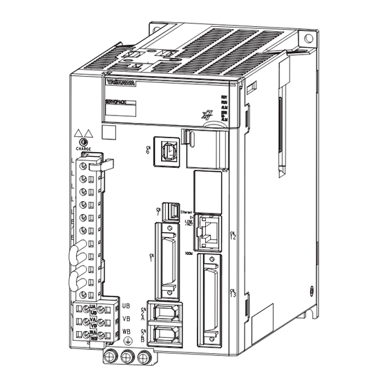
Page 36: Part Names
1.3 Part Names 1.3.1 Σ-7W Part Names The part names of the SERVOPACK are given below. Parts that are indicated by are unique to the SERVOPACKs with the HWBB function. Σ -7W 1.3.1 With Front Cover Open Main circuit terminal (on ide of ERVOPACK) Bottom of the ERVOPACK... -
Page 37: Σ-7C
1.3 Part Names 1.3.2 Σ-7C Continued from previous page. Name Description Reference Rotary Switches (S1 and S2) Used to set the MECHATROLINK station address. Lights when the control power is being supplied. – L1, L2 Lights during MECHATROLINK communications. – Lights when the SERVOPACK normally receives a CON- –... - Page 38 1.3 Part Names 1.3.2 Σ-7C Continued from previous page. Name Description Reference Servomotor Terminals (Axis These terminals are used to connect the main circuit cable A: UA, VA, and WA; Axis B: – (power line) to the Servomotor. UB, VB, and WB) The ground terminal helps prevent electric shock.
-
Page 39: Model Designations
1.4 Model Designations 1.4.1 Σ-7W Model Designations Σ -7W 1.4.1 GD7W - 1R6 14th 5th+6th 1 t+2nd+ rd 8th+9th+10th 11th+12th+1 th Σ-7- erie digit digit digit digit digit digit digit Σ-7W ERVOPACK Hardware Option Maximum Applicable 1 t+2nd+ rd digit 8th+9th+10th digit 4th digit Voltage... -
Page 40: Σ-7C
1.4 Model Designations 1.4.2 Σ-7C Σ -7C 1.4.2 GD7C - 1R6 1 t+2nd+ rd digit 5th+6th digit 8th+9th+10th digit 4th digit 7th digit Σ-7- erie Σ-7C ERVOPACK Maximum Applicable Interface *3 1 t+2nd+ rd digit 5th+6th digit Motor Capacity per Axi pecification Voltage Code... -
Page 41: Selecting A Servopack
Selecting a SERVOPACK This chapter provides information required to select SERVOPACKs, such as general specifications, block dia- grams, connector specifications, external dimensions, and connection examples. General Specifications ....2-2 Σ-7W . -
Page 42: General Specifications
2.1 General Specifications 2.1.1 Σ-7W General Specifications This section gives the general specifications of SERVOPACKs. Specifications that are indicated by are unique to the SERVOPACKs with the HWBB func- tion. Σ -7W 2.1.1 Item Specification Control Method IGBT-based PWM control, sine wave current drive Serial encoder: 20 bits or 24 bits (incremental encoder/absolute With Rotary encoder) - Page 43 2.1 General Specifications 2.1.1 Σ-7W Continued from previous page. Item Specification Linear Servomotor Number of input points: 2 Overheat Protection Input voltage range: 0 V to +5 V Signal Input Allowable voltage range: 24 VDC ±20% Number of input points: 12 Input method: Sink inputs or source inputs Input Input Signals...
- Page 44 2.1 General Specifications 2.1.1 Σ-7W Continued from previous page. Item Specification Position, speed, or torque control with MECHATROLINK-III communi- Performance cations Reference MECHATROLINK-III commands (sequence, motion, data setting, data Method Reference Input access, monitoring, adjustment, etc.) MECHATROLINK-III standard servo profile Profile Rotary switch (S1 and S2) positions: 16 MECHATROLINK-III Communica-...
-
Page 45: Σ-7C
2.1 General Specifications 2.1.2 Σ-7C Σ -7C 2.1.2 This section gives the general specifications of Σ-7C SERVOPACKs and the specifications of the Servo Section. Refer to the following manual for the specifications of the Controller Section. Σ Σ -7-Series -7C SERVOPACK Product Manual (Manual No.: SIEP S800002 04) General Specifications Item Specification... - Page 46 2.1 General Specifications 2.1.2 Σ-7C Continued from previous page. Item Specification Linear Servomotor Number of input points: 2 Overheat Protection Input voltage range (0 V to 5 V) Signal Input Allowable voltage range: 24 VDC ±20% Number of input points: 12 Input method: Sink inputs or source inputs Input Signals: Input...
-
Page 47: Block Diagrams
2.2 Block Diagrams 2.2.1 SGD7W-1R6A and -2R8A Block Diagrams This section gives the block diagrams of SERVOPACKs with the HWBB function. For the Σ-7C SERVOPACKs, a block diagram is given for the Servo Section only. Parts that are indicated by are unique to the SERVOPACKs with the HWBB function. -
Page 48: Sgd7W-5R5A And -7R6A
2.2 Block Diagrams 2.2.2 SGD7W-5R5A and -7R6A 2.2.2 SGD7W-5R5A and -7R6A ervomotor for axi A Vari tor Main circuit − power CHARGE upply Dynamic brake circuit Voltage Relay drive en or Dynamic brake circuit Gate drive Gate drive Voltage Current Current Temperature Gate drive... -
Page 49: Sgd7C-1R6A And -2R8A
2.2 Block Diagrams 2.2.3 SGD7C-1R6A and -2R8A 2.2.3 SGD7C-1R6A and -2R8A ervomotor for axi A Vari tor Main circuit power − CHARGE upply Dynamic brake circuit Voltage Relay drive en or Dynamic brake circuit Gate drive Gate drive Voltage Current Current Temperature Gate drive... -
Page 50: Sgd7C-5R5A And -7R6A
2.2 Block Diagrams 2.2.4 SGD7C-5R5A and -7R6A 2.2.4 SGD7C-5R5A and -7R6A ervomotor for axi A Vari tor Main circuit power − CHARGE upply Dynamic brake circuit Voltage Relay drive en or Dynamic brake circuit Gate drive Gate drive Voltage Current Current Temperature Gate drive... -
Page 51: External Dimensions
2.3 External Dimensions 2.3.1 Front Cover Dimensions and Connector Specifications External Dimensions 2.3.1 Front Cover Dimensions and Connector Specifications This section gives the front cover dimensions and connector specifications. Parts that are indi- cated by are unique to the SERVOPACKs with the HWBB function. Σ... - Page 52 2.3 External Dimensions 2.3.1 Front Cover Dimensions and Connector Specifications Σ The front cover dimensions and panel connector section are the same for all models. Refer to the following figures and table. • Front Cover Dimensions (12) Front cover CN12 CN2A CN2B •...
-
Page 53: Servopack External Dimensions
2.3 External Dimensions 2.3.2 SERVOPACK External Dimensions 2.3.2 SERVOPACK External Dimensions Σ • Three-phase, 200 VAC: SGD7W-1R6A and -2R8A ×M4 Exterior 60 ±0.5 (26) (mounting pitch) Ground terminal (76) × M4 Mounting Hole Diagram Approx. ma : 1.6 kg Unit: mm •... - Page 54 2.3 External Dimensions 2.3.2 SERVOPACK External Dimensions Σ • Three-phase, 200 VAC: SGD7C-1R6A and -2R8A 4 × M4 Exterior 90 ±0.5 (26) 17 (mounting pitch) Ground terminal (76) (180) × M4 crew Mounting Hole Diagram Approx. ma : 2.0 kg Unit: mm •...
-
Page 55: Examples Of Standard Connections Between Servopacks And Peripheral Devices
External Regenerative Resistors are not provided by Yaskawa. The power supply for the holding brake is not provided by Yaskawa. Select a power supply based on the hold- ing brake specifications. If you use a 24-V brake, install a separate power supply for the 24-VDC power supply from other power supplies, such as the one for the I/O signals of the CN1 connector. -
Page 56: 2.4.1 Σ-7W
Converter Unit erial Converter Unit Linear Encoder Cable Linear Encoder Cable en or Cable en or Cable Linear encoder Linear encoder Linear ervomotor for axi A Linear ervomotor for axi B External Regenerative Resistors are not provided by Yaskawa. 2-16... -
Page 57: Σ-7C
Direct Drive ervomotor for axi B External Regenerative Resistors are not provided by Yaskawa. The power supply for the holding brake is not provided by Yaskawa. Select a power supply based on the hold- ing brake specifications. If you use a 24-V brake, install a separate power supply for the 24-VDC power supply from other power sup- plies, such as the one for the I/O signals of the CN1 or CN13 connector. - Page 58 Cable Linear Encoder Cable Cable Cable Linear Linear encoder encoder ervomotor ervomotor ervomotor Linear ervomotor for axi B Linear ervomotor for axi A Up to 8 tation , including I/O External Regenerative Resistors are not provided by Yaskawa. 2-18...
-
Page 59: Servopack Installation
SERVOPACK Installation This chapter provides the EMC installation conditions for SERVOPACKs that have the HWBB function. EMC Installation Conditions ... . 3-2 Σ-7W ........3-2 3.1.1 Σ-7C . -
Page 60: Emc Installation Conditions
The EMC installation conditions that are given here are the conditions that were used to pass testing criteria at Yaskawa. The EMC level may change under other conditions, such as the actual installation structure and wiring conditions. These Yaskawa products are designed to be built into equipment. -
Page 61: Σ-7C
3.1 EMC Installation Conditions 3.1.2 Σ-7C Continued from previous page. Symbol Cable Name Specification Motor Main Circuit Cable for axis B Shielded cable Encoder Cable for axis B Shielded cable Main Circuit Power Cable Shielded cable MECHATROLINK-III Communications Cable Shielded cable ... - Page 62 3.1 EMC Installation Conditions 3.1.2 Σ-7C Continued from previous page. Code Cable Name Specification Motor Main Circuit Cable for axis B Shielded cable Encoder Cable for axis B Shielded cable Main Circuit Power Cable Shielded cable MECHATROLINK-III Communications Cable Shielded cable ...
-
Page 63: Wiring And Connecting Servopacks
Wiring and Connecting SERVOPACKs This chapter provides information on wiring and connecting SERVOPACKs to power supplies and peripheral devices. Wiring and Connecting SERVOPACKs ..4-2 Basic Wiring Diagrams ....4-5 Σ-7W . -
Page 64: Wiring And Connecting Servopacks
4.1 Wiring and Connecting SERVOPACKs Wiring and Connecting SERVOPACKs DANGER Do not change any wiring while power is being supplied. There is a risk of electric shock or injury. WARNING Wiring and inspections must be performed only by qualified engineers. There is a risk of electric shock or product failure. - Page 65 Whenever possible, use the Cables specified by Yaskawa. If you use any other cables, confirm the rated current and application environment of your model and use the wiring materials specified by Yaskawa or equivalent materials. Securely tighten cable connector screws and lock mechanisms.
- Page 66 To ensure safe, stable application of the servo system, observe the following precautions when wiring. • Use the cables specified by Yaskawa. Design and arrange the system so that each cable is as short as possible. Refer to the following manual for information on the specified cables.
-
Page 67: Basic Wiring Diagrams
Connect these when using an absolute encoder. If the Encoder Cable with a Battery Case is connected, do not connect a backup battery. The 24-VDC power supply is not provided by Yaskawa. Use a 24-VDC power supply with double insulation or reinforced insulation. -
Page 68: Σ-7C
4.2 Basic Wiring Diagrams 4.2.2 Σ-7C Refer to the following chapter for details. Chapter 5 Safety Functions If you do not use the safety function, insert the Safety Jumper Connector (provided as an accessory) into CN8 when you use the SERVOPACK. Note: 1. - Page 69 Connect these when using an absolute encoder. If the Encoder Cable with a Battery Case is connected, do not connect a backup battery. The 24-VDC power supply is not provided by Yaskawa. Use a 24-VDC power supply with double insulation or reinforced insulation.
-
Page 70: Connecting The Hwbb Function Signal
4.3 Connecting the HWBB Function Signal 4.3.1 Safety Function Connector (CN8) Pin Arrangement Connecting the HWBB Function Signal This section describes the wiring that is required to use the HWBB function. Refer to the following chapter for details on the HWBB function. Chapter 5 Safety Functions 4.3.1 Safety Function Connector (CN8) Pin Arrangement... - Page 71 4.3 Connecting the HWBB Function Signal 4.3.2 I/O Circuits Input (HWBB) Signal Specifications Connector Type Signal Status Meaning Pin No. Does not activate the HWBB function (normal ON (closed) operation). CN8-4 /HWBB1 CN8-3 Activates the HWBB function (motor current shut- OFF (open) OFF request).
- Page 72 Safety Functions This chapter provides details on the HWBB function as a safety function of the SERVOPACKs. Introduction to the HWBB Function ..5-2 5.1.1 What Is the HWBB Function? ....5-2 5.1.2 Precautions for the HWBB Function .
-
Page 73: Introduction To The Hwbb Function
5.1 Introduction to the HWBB Function 5.1.1 What Is the HWBB Function? Introduction to the HWBB Function 5.1.1 What Is the HWBB Function? An HWBB function is built into the SERVOPACK to reduce the risks associated with using the machine by protecting workers from the hazards of moving machine parts and otherwise increasing the safety of machine operation. -
Page 74: Hwbb Function
5.2 HWBB Function HWBB Function The HWBB function uses a hardwired circuit to shut off the current to the motors. The drive signals to the Power Module that controls the motor current are controlled by the cir- cuits that are independently connected to the two input signal channels to turn OFF the Power Module and shut OFF the motor current. -
Page 75: Risk Assessment
5.2 HWBB Function 5.2.1 Risk Assessment 5.2.1 Risk Assessment When using the HWBB function, you must perform a risk assessment of the servo system in advance to confirm that the safety level of the standards is satisfied. Refer to the following sec- tion for details on the standards. - Page 76 5.2 HWBB Function 5.2.2 HWBB State • When HWBB Function Operates after Servo OFF (Power Not Supplied to Motor) /HWBB1 (normal operation) (motor current hut-OFF reque t) /HWBB2 MECHATROLINK-III Motion command V_OFF MON command command for axi A and other command command and other command V_ON command...
- Page 77 5.2 HWBB Function 5.2.2 HWBB State • When HWBB Function Operates While Power Is Supplied to Servomotor /HWBB1 (normal operation) (motor current hut-OFF reque t) /HWBB2 MECHATROLINK-III Motion command MON command command for axi A and other command and other command V_ON command tatu for axi A E TP command...
-
Page 78: Resetting The Hwbb State
5.2 HWBB Function 5.2.3 Resetting the HWBB State 5.2.3 Resetting the HWBB State The following examples use the Σ-7W SERVOPACK with MECHATROLINK-III commands. If you use a Σ-7C SERVOPACK, you will need to use Controller Section commands instead of MECHA- TROLINK-III commands. -
Page 79: Related Commands
5.2 HWBB Function 5.2.4 Related Commands If the /HWBB1 and /HWBB2 signals are OFF and the SV_ON (Servo ON: 31 hex) command is received, the HWBB state will be maintained even after the /HWBB1 and /HWBB2 signals are turned ON. Send the SV_OFF (Servo OFF: 32 hex) command for axis A and axis B to place the SERVOPACK in the BB state and then send the SV_ON (Servo ON: 31 hex) command. -
Page 80: Detecting Errors In Hwbb Signal
5.2 HWBB Function 5.2.5 Detecting Errors in HWBB Signal 5.2.5 Detecting Errors in HWBB Signal If only the /HWBB1 or the /HWBB2 signal is input, an A.Eb1 alarm (Safety Function Signal Input Timing Error) will occur unless the other signal is input within 10 seconds. This makes it possi- ble to detect failures, such as disconnection of an HWBB signal. -
Page 81: Operation Without A Host Controller
5.2 HWBB Function 5.2.8 Operation without a Host Controller 5.2.8 Operation without a Host Controller The HWBB function will operate even for operation without a host controller. However, if the HWBB function operates during execution of the following functions, leave the execution mode for the function and then enter it again to restart operation. -
Page 82: Bk (Brake Output) Signal
5.2 HWBB Function 5.2.10 /BK (Brake Output) Signal 5.2.10 /BK (Brake Output) Signal If the HWBB function operates when the /HWBB1 or /HWBB2 signal is OFF, the /BK (Brake) signal will turn OFF. At that time, the setting in Pn506 (Brake Reference - Servo OFF Delay Time) will be disabled. -
Page 83: Edm1 (External Device Monitor)
5.3 EDM1 (External Device Monitor) 5.3.1 EDM1 Output Signal Specifications EDM1 (External Device Monitor) The EDM1 (External Device Monitor) signal is used to monitor failures in the HWBB function. Connect the monitor signal as a feedback signal, e.g., to the Safety Unit. Note: To meet performance level e (PLe) in EN ISO 13849-1 and SIL3 in IEC 61508, the EDM1 signal must be mon- itored by the host controller. -
Page 84: Hwbb Function Application Example
5.4 HWBB Function Application Example 5.4.1 Connection Example HWBB Function Application Example This section provides examples of using the HWBB function. 5.4.1 Connection Example In the following example, a Safety Unit is used as the host controller and the HWBB function operates when the guard is opened. -
Page 85: Procedure
5.4 HWBB Function Application Example 5.4.3 Procedure 5.4.3 Procedure Request is received to open the guard. If the motor is operating, a stop command is received from the host controller, the motor stops, and the servo is turned OFF. The guard is opened. The /HWBB1 and /HWBB2 signals turn OFF and the HWBB function operates. -
Page 86: Validating The Hwbb Function
5.5 Validating the HWBB Function Validating the HWBB Function When you commission the system or perform maintenance or SERVOPACK replacement, you must always perform the following validation test on the HWBB function after completing the wiring. (It is recommended that you keep the confirmation results as a record.) •... -
Page 87: Connecting The Safety Function Device
5.6 Connecting the Safety Function Device Connecting the Safety Function Device This section describes how to connect the SERVOPACK to a safety function device. Use a pair of pliers or a similar tool to remove the Safety Jumper Connector from the connector for the safety function device (CN8). -
Page 88: Maintenance
Maintenance This chapter provides information on the meaning of, causes of, and corrections for alarms that are related to the HWBB function. Alarm Displays ..... . 6-2 6.1.1 Alarms Related to the HWBB Function . -
Page 89: Alarm Displays
6.1 Alarm Displays 6.1.1 Alarms Related to the HWBB Function Alarm Displays If an error occurs in the SERVOPACK, an alarm number will be displayed on the panel display or SigmaWin+. When an alarm is displayed on the panel display, the display will change in the following order. Example: Alarm A.E60 Status Not lit. -
Page 90: Troubleshooting Alarms Related To The Hwbb Function
6.1.2 Troubleshooting Alarms Related to the HWBB Function The following table describes troubleshooting alarms that are related to the HWBB function. Contact your Yaskawa representative if you cannot solve a problem with the corrections given in the table. Alarm Number:... -
Page 91: Troubleshooting Based On The Operation And Conditions Of The Servomotor
6.2 Troubleshooting Based on the Operation and Conditions of the Servomotor Troubleshooting Based on the Operation and Conditions of the Servomotor This section provides troubleshooting information related to the HWBB function based on the operation and conditions of the Servomotor, including causes and corrections. Refer to the following manual for your SERVOPACK for information on the causes of and cor- rections for other problems. -
Page 92: Appendices
Appendices This appendices provide information on interpreting panel displays that are unique to the HWBB function, and tables of corresponding SERVOPACK and SigmaWin+ function names. Interpreting Panel Displays ... . . 7-2 7.1.1 Panel Display during the HWBB State . -
Page 93: Interpreting Panel Displays
7.1 Interpreting Panel Displays 7.1.1 Panel Display during the HWBB State Interpreting Panel Displays You can check the Servo Drive status on the panel display of the SERVOPACK. Also, if an alarm or warning occurs, the alarm or warning number will be displayed. This section describes the panel displays during the HWBB state. -
Page 94: Corresponding Servopack And Sigmawin+ Function Names
7.2 Corresponding SERVOPACK and SigmaWin+ Function Names 7.2.1 Corresponding SERVOPACK Monitor Display Function Names Corresponding SERVOPACK and SigmaWin+ Function Names The following table gives the corresponding monitor display names between the SERVOPACK and SigmaWin+ that are related to the HWBB function. Refer to the following manual for the the compatibility with other monitor display names. -
Page 95: Index
Index Index - - - - - - - - - - - - - - - - - - - - - - - - - - - xii Servo Drive - - - - - - - - - - - - - - - - - - - - - - - - - - - - xii servo lock - - - - - - - - - - - - - - - - - - - - - - - - - - - - xii servo OFF... -
Page 96: Revision History
Revision History The revision dates and numbers of the revised manuals are given on the bottom of the back cover. MANUAL NO. SIEP S800001 72B <1> Revision number Published in Japan July 2016 Date of publication Date of Rev. Section Revised Contents Publication Front cover... - Page 97 Phone 81-4-2962-5151 Fax 81-4-2962-6138 http://www.yaskawa.co.jp YASKAWA AMERICA, INC. 2121, Norman Drive South, Waukegan, IL 60085, U.S.A. Phone 1-800-YASKAWA (927-5292) or 1-847-887-7000 Fax 1-847-887-7310 http://www.yaskawa.com YASKAWA ELÉTRICO DO BRASIL LTDA. 777, Avenida Piraporinha, Diadema, São Paulo, 09950-000, Brasil Phone 55-11-3585-1100 Fax 55-11-3585-1187 http://www.yaskawa.com.br...
Need help?
Do you have a question about the SERVOPACK Sigma 7W Series and is the answer not in the manual?
Questions and answers