Table of Contents
Advertisement
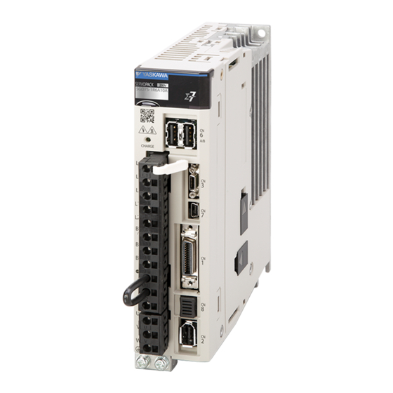
-7-Series AC Servo Drive
-7S SERVOPACK with
FT/EX Specification for
Transfer and Alignment Application
with Special Motor, SGM7D Motor
Product Manual
Model: SGD7S-20AF84
SGD7S-30AF84
MANUAL NO. SIEP S800002 28C
Basic Information on SERVOPACKs
SERVOPACK Ratings and Specifications
Triggers at Preset Positions
Rotational Coordinate System
Maintenance
Parameter Lists
1
2
3
4
5
6
Advertisement
Table of Contents
Troubleshooting


Need help?
Do you have a question about the Sigma-7-Series and is the answer not in the manual?
Questions and answers