
Related Manuals for Teledyne Sierra M6-2


Summary of Contents for Teledyne Sierra M6-2
- Page 1 Sierra M6-2 SAS/SATA Protocol Analyzer User Manual For software version 5.80 Generated: March 3, 2015, 10:54...
- Page 2 Teledyne LeCroy Teledyne LeCroy Protocol Solutions Group Trademarks and Servicemarks: Teledyne LeCroy, Teledyne LeCroy Protocol Solutions Group, CATC, SAS/SATA Protocol Suite, SASTracer, SATracer, SAS‐ Trainer, SATrainer, SASTracker and Avalanche are trademarks of Teledyne LeCroy. Microsoft, Windows, Windows 2000,Windows XP, Windows Vista and Windows 7 are registered trademarks of Microsoft Inc. Intel and Pentium are registered trademarks of Intel Corporation. All other trademarks and registered trademarks are property of their respective owners. THE SPECIFICATIONS AND INFORMATION REGARDING THE PRODUCTS IN THIS MANUAL ARE SUBJECT TO CHANGE WITHOUT NOTICE. ALL INFORMATION, EXAMPLES AND RECOMMENDATIONS IN THIS MANUAL ARE BELIEVED TO BE ACCURATE BUT ARE REPRESENTED WITHOUT WARRANTY OF ANY KIND, EXPRESS OR IMPLIED. USERS ARE FULLY RESPONSIBLE FOR THEIR APPLICATION OF ANY PRODUCTS. THE SOFTWARE LICENSE AND LIMITED WARRANTY FOR THE ACCOMPANYING PRODUCT ARE SET FORTH IN INFORMATION THAT SHIPPED WITH THE PRODUCT AND ARE INCORPORATED HEREIN BY THIS REFERENCE. IF YOU ARE UNABLE TO LOCATE THE SOFTWARE LICENSE OR LIMITED WARRANTY, CONTACT TELEDYNE LECROY FOR A COPY. © 2012 Teledyne LeCroy, Inc. All rights reserved. This document may be printed and reproduced without additional permission, but all copies should contain this copy‐ right notice. WEEE Program Teledyne LeCroy 3385 Scott Blvd. Santa Clara, CA 95054 TEL: 800‐909‐7112 (USA and Canada) TEL: 408‐653‐1260 (worldwide) Sierra M6‐2 SAS/SATA Protocol Analyzer User Manual...
-
Page 3: Table Of Contents
Contents Chapter 1: Introduction..................17 1.1 Analyzer Overview........................ 17 1.2 Features..........................18 1.3 Receiving Your Analyzer ...................... 18 1.4 Unpacking the Analyzer ....................... 19 1.5 Analyzer Features......................... 19 1.6 LEDs............................19 1.6.1 Status and Configuration Display ......................20 1.6.2 Temperature and Humidity........................20 1.7 Installing Your Analyzer ....................... - Page 4 1.18 Protocol Analyzer Initiator Emulator or Host Emulator ..........39 1.19 Performance Analyzer......................40 1.20 Target Emulator or Device Emulator................. 40 1.21 Teledyne LeCroy SAS/SATA Protocol Suite Menu Options and Toolbars..... 40 1.21.1 File ................................41 1.21.2 Setup ................................. 41 1.21.3 Session ..............................
- Page 5 Contents Teledyne LeCroy 2.5.7 Export Paired SAS Address Report ......................61 2.5.8 Trace Properties............................62 2.5.9 Edit Comment............................. 62 2.6 Projects..........................63 New Default Project ..........................63 Last Project............................63 2.6.1 Project File Types ............................63 2.6.2 Example Projects ............................64 2.6.3 Run an Example Analysis Project ......................
- Page 6 Teledyne LeCroy Contents Bus Condition............................87 Symbol ..............................87 Primitive ............................... 88 ATA Command ............................ 90 ATAPI ..............................91 Data Pattern ............................92 Training Sequence ..........................93 Protocol Errors............................ 94 STP Frame ............................95 Address Frame (SAS only)......................... 96 SMP Frame (SAS only) ........................97 SSP Frame (SAS only) ........................
- Page 7 Contents Teledyne LeCroy Ports Configuration .......................... 112 Port Configuration and Projects...................... 114 MUX Setting (SAS only)........................115 2.6.20 Add a Project Note ..........................116 2.7 Advanced Mode (User-Defined) ..................117 2.7.1 Working in Advanced Mode ........................117 State Number for Complex Trigger Sequences ................119 Setting Trigger Conditions.......................
- Page 8 Teledyne LeCroy Contents 2.9.5 Initiator Setting Tab (SAS only) ......................161 2.9.6 Host Setting Tab (SATA) ......................... 166 2.9.7 Project Settings............................172 2.9.8 Creating a Data Block ..........................172 Naming a Data Block ........................174 Editing a Data Block ......................... 174 Creating and Editing Data Blocks as Text ..................
- Page 9 Contents Teledyne LeCroy Chapter 3: Display Manipulation ...............221 3.1 Viewer Display ........................221 3.1.1 Scrolling..............................221 3.1.2 Quick View ..............................222 3.1.3 Using the Viewer Display ........................223 3.2 Trace Properties........................223 3.3 Analysis ..........................224 3.3.1 Show Analysis Toolbar ........................... 224 3.3.2 Decoding Assignments ...........................
- Page 10 Teledyne LeCroy Contents SSP Transport Report (SAS)......................251 SMP Transport Report (SAS) ......................252 SCSI Command Report (SAS)......................253 SMP Command Report (SAS) ......................253 Task Command Report (SAS) ......................253 SAS Address Report (SAS) ......................254 Lanes Report (SAS) .......................... 254 Read/Write Command Report (SAS) ....................
- Page 11 Contents Teledyne LeCroy 3.8 Navigation + View Toolbar ....................282 3.8.1 Go To Menu .............................. 283 Locate Cursors..........................283 Go to Time Stamp ..........................284 Bookmarks............................284 Editing a Bookmark .......................... 285 Finding a Bookmark.......................... 285 Bookmark Description........................286 Set Time Stamp Origin........................287 3.8.2 Filtering ..............................
- Page 12 Teledyne LeCroy Contents 3.8.9 Show/Hide Ports ............................305 Single Port ............................305 Multiple Ports ............................ 305 3.9 Packet View Toolbar ......................305 3.9.1 CATC Navigation View ..........................307 3.9.2 Spec View ..............................308 3.9.3 Decode Icons............................309 3.9.4 Customize Display ........................... 310 Rename Port ............................
- Page 13 External Trig In Setting........................337 3.21 Update Device ........................337 3.22 User-Defined Decoding ....................339 3.23 Help Menu.......................... 340 3.23.1 Tell Teledyne LeCroy ..........................340 3.23.2 Help Topics............................. 340 3.23.3 VSE Help Topics ............................ 340 3.23.4 Update License ............................340 3.23.5 Display License Information .........................
- Page 14 Teledyne LeCroy Contents 4.2.2 Menus................................ 370 File ..............................370 Setup ..............................370 View ..............................370 Configuration............................. 370 Tools..............................371 Help ..............................371 4.2.3 Main Library.............................. 371 4.2.4 File Library..............................371 4.2.5 Device Ports ............................. 372 Using the Device Ports Dialog ......................372 4.3 Port Configuration for InFusion ..................
- Page 15 Contents Teledyne LeCroy 4.9.6 Example 6: Using Timers ........................410 4.10 Creating a Sequence ......................412 4.10.1 Example 7: Creating Two Sequences and Global Rules ..............413 4.11 Example 8: Creating a Sequence With Many States #1..........419 4.12 Example 9: Creating a Sequence With Many States #2..........422 4.13 Downloading Scenarios ....................
- Page 16 Teledyne LeCroy Contents 5.7.4 Placing Global Settings in the Generation Block.................. 448 5.8 Primitive and Frame Definitions..................450 5.8.1 Special Conditions for Frames ....................... 450 5.8.2 Primitives Decl.inc File ..........................451 5.8.3 Address FramesDecl.inc File ........................451 5.8.4 SSPFrames.inc File..........................451 5.8.5 SMPFrames.inc File ..........................
- Page 17 Contents Teledyne LeCroy 5.13.8 Procedure Definition..........................472 5.14 Sierra Trainer Generation Commands ................472 5.14.1 General Commands ..........................472 5.14.2 SATA Commands........................... 475 5.14.3 Primitive Commands ..........................475 5.14.4 Primitive Category ..........................478 5.14.5 Wait Commands ............................. 479 5.14.6 Wait Command Groups ........................485 5.14.7 Predefined Constants ..........................
- Page 18 6.6 Role definition format......................519 6.7 END_OF_FILE definition ....................519 6.8 Example Pattern Generator File ..................520 Appendix B: China Restriction of Hazardous Substances Table ....521 7.1 WAN Operation ........................522 Appendix C: How to Contact Teledyne LeCroy..........523 Index:........................525 Sierra M6‐2 SAS/SATA Protocol Analyzer User Manual...
-
Page 19: Chapter 1: Introduction
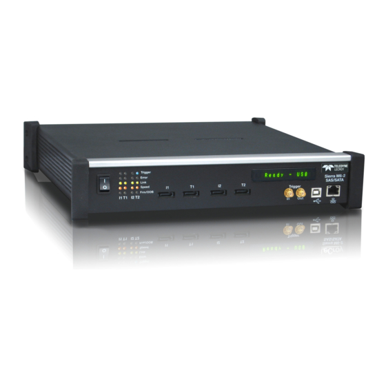
Chapter 1 Introduction This manual describes installation and operation of the Teledyne LeCroy Sierra M6‐2™ Protocol Analyzer and includes examples of typical applications. Figure 1.1: Teledyne LeCroy Sierra M6-2 Protocol Analyzer Analyzer Overview The Sierra M6‐2 SAS/SATA Protocol Analyzer is a serial bus analyzer, supports host and device emulation, generates traffic, and provides error injection functionality. The SAS analyzer software performs serial bus analysis for Serial Attached SCSI (SAS) data transfers, as well as Serial ATA (SATA) data transfers through STP data transfers. The SATA analyzer software performs serial bus analysis for Serial ATA (SATA) data transfers. The Sierra M6‐2 Analyzer helps Hardware, Firmware, Design, and Application Engineers troubleshoot and diagnose SAS and SATA problems within their product. The analyzer supports the following: Capture, triggering, and filtering of Serial Attached SCSI packets or Serial ATA packets Generation of bus traffic as a SAS Initiator Emulator or a SATA Host Emulator, while monitoring and analyzing results SAS target emulation and SATA device emulation ... -
Page 20: Features
Teledyne LeCroy Features The analyzer provides for bi‐directional trigger and capture of commands, primitives, patterns and all bus conditions. You can capture all frames and/or exclude traffic. The InFusion™ Error Injector and Traffic Modifier is an error injector and traffic modification tool that allows you to verify real‐world fault handling. The Trainer is a traffic generator that can emulate a SAS initiator/target or SATA host/ device. The Sierra M6‐2 Analyzer has a USB port and an Ethernet port to connect to a computer. You can cascade analyzer units for higher port counts. The analyzer allows you to select frames to include and exclude for capture. Capturing can be triggered based on a specific event or manually. The Sierra M6‐2 Analyzer provides a full range of views and statistical reports. Features 6 Gb/s SAS/SATA protocol analysis or error injection Native PHY for fast lock time Easy mode triggering Cascade up to 8 analyzers Sync with Teledyne LeCroy Sierra and STX family products CrossSync Control Panel Hardware filtering Automatic error detection Comprehensive decoding of SAS and SATA data traffic Logical and chronological traffic displays Statistical reporting Trace memory of 4 GB or 8 GB GbE & USB 2.0 host interfaces ... -
Page 21: Unpacking The Analyzer
Unpacking the Analyzer Teledyne LeCroy 1 Sierra M6‐2 Getting Started manual Unpacking the Analyzer Inspect the received shipping container for any damage. Unpack the container and account for each of the system components listed on the accompanying packing list. Visually inspect each component for absence of damage. In the event of damage, notify the shipper and Teledyne LeCroy Corporation. Retain all shipping materials for shipper’s inspection. Analyzer Features The Analyzer has the following features: Power Switch (0/1) Trigger, Error, Link, Speed, and Frame/OOB LEDs (see next page) Port 1 Initiator/Host SATA connector Port 1 Target/Device SATA connector Port 2 Initiator/Host SATA connector Port 2 Target/Device SATA connector Status and Configuration LCD Display External Trigger Input and Output USB port for host connectivity Gigabit Ethernet port for network connectivity Power In (on back) Expansion In/Out data ports and Clock In/Out connectors (on back) Figure 1.2: Front Panel LEDs Each link is supported by LEDs with the following functionality:... -
Page 22: Status And Configuration Display
Teledyne LeCroy Installing Your Analyzer 6.0G Yellow This LED is illuminated when a link is established. This LED illuminates when an error occurs. Blue This LED is illuminated when a trigger occurs. Figure 1.3: LEDs 1.6.1 Status and Configuration Display The Analyzer front LCD display indicates the configuration and status of operations. For example, during initialization, the LCD panel displays boot status messages. 1.6.2 Temperature and Humidity The hardware should operate flawlessly in the following temperature ranges: Operating 0 °C to 55 °C (32 °F to 131 °F) Non‐Operating ‐20 °C to 80 °C (‐4 °F to 176 °F) The hardware should operate in the following humidity range: 10% to 90% RH (non‐condensing) Installing Your Analyzer 1.7.1 Software Installation The SAS and SATA software works on systems using the Windows® XP, Windows 7 (x86, x64) Windows 8 (x86, x64), Windows Server 2003, Windows Server 2008 and Windows Server 2012 R2 operating systems. 64‐bit Windows OS is recommended because it allows using more RAM memory. Other Operating Systems limit the RAM to 3GB. -
Page 23: System Restart
Hardware Setup Teledyne LeCroy 4. Select components for installation. 5. Click Next to complete the installation. System restart You must restart your computer before you can use your Analyzer software. Error Message If you get an error message during installation of the drivers for Window, consult your system administrator. Your system may allow only administrator‐level users to copy such driver files. Hardware Setup 1.8.1 Separate Systems When using the analyzer, it is recommended to use a system to generate bus traffic and a second system to run the software, to avoid characterization of traffic generated by the analyzer. 1.8.2 Connecting in General Note: You must install the software before connecting the analyzer to the host machine for the first time. To set up the analyzer: 1. Plug the power adapter into the unit, and then plug the power adapter into a 100V– 240V, 50Hz–60Hz, power outlet. Turn on the Power switch. At power on, the analyzer will go through initialization as shown on the LCD display. 2. Connect the USB cable between the Sierra M6‐2 USB port and a USB port on the host machine. The host machine operating system detects the analyzer and driver files. (See “Connecting via Ethernet” on page 36 for Ethernet connectivity.) 3. -
Page 24: Cables To Use
Teledyne LeCroy Hardware Setup Figure 1.4: Analyzer Connections 1.8.3 Cables to Use When using Sierra as a Host Emulator, connect from Target to hard drives using a SATA cable. When using Sierra as a Device Emulator, connect from Initiator to HBAs using a SATA cable. Sierra M6‐2 SAS/SATA Protocol Analyzer User Manual... -
Page 25: Expandability
Expandability Teledyne LeCroy Figure 1.5: Sierra M6-2 Connected as an Analyzer Expandability You can expand by: Cascading with STX SYNC Expansion Cards Cascading with CATC SYNC Expansion Cards Using the Power Expansion Card You can remove expansion cards with two simple tools. Sierra M6‐2 SAS/SATA Protocol Analyzer User Manual... -
Page 26: Cascading With Stx Sync Expansion Cards
Teledyne LeCroy Expandability Cascading and Memory Size For example, you have two units. The first one has 2 GB memory. The second one has 4 GB memory. The system shows the entire memory as 6 GB. If you set buffer size to 6 GB, the system programs the first board for 2 GB and the second board for 4 GB. You can consider this ratio when you set buffer size to any value. For example, if you set buffer size to 2 GB, the system programs the first board for (2*2)/6 GB and the second board for (2*4)/6 GB. Any unit that has more memory will have larger buffer size. 1.9.1 Cascading with STX SYNC Expansion Cards You can use cascading of analyzer units for higher port count, by daisy chaining the units through the provided Expansion and Clock In/Out interfaces on the analyzer back. Connect “Out” connectors to “In” connectors of the next unit in the chain, for both Signal and Clock interfaces. You must provide external hubs for connecting the host machine to these units using USB or Ethernet. You can cascade up to eight units. Use the STX SYNC Expansion Cards to sequentially trigger the State Machine in Advanced mode. If you mix Sierra M6‐4, Sierra M6‐2, and STX A6‐4 analyzers/emulators, put Sierra boards first, then STX. Note: Because chain connections for cascading boards cause delay of signals, traffic on different boards is not completely time synchronized, with about one DWORD difference between ... - Page 27 Expandability Teledyne LeCroy Note: The Self Test, SAS Verification Test, SATA Compliance Test and Update License functions only work on unit 1 when the analyzers are set up in cascading mode. Figure 1.7: Cascading Correct way to connect: The black color pin of the ribbon wire is connected the same way between 2 connectors. Cascading works correctly in this case. Black color pin of ribbon wire Figure 1.8: Cascading Correctly...
-
Page 28: Select Device
Teledyne LeCroy Expandability Incorrect way to connect: The black color pin of the ribbon wire is connected in a different way between the 2 connectors. Cascading works incorrectly in this case, the boxes are connected but no traces are captured. - Page 29 Expandability Teledyne LeCroy Figure 1.11: Connecting to All SAS Devices. The Select Device dialog allows connecting and disconnecting analyzers on the fly, without restarting the application. The new Device List (introduced in version 4.10) mandates using updated firmware in order to detect the analyzer over Ethernet. Thus, the analyzer must be updated over USB before it can be used remotely over Ethernet.
- Page 30 Teledyne LeCroy Expandability Figure 1.12: Select Device Dialog. Note: Click Refresh Device List to display all the devices on the network. The Select Device dialog displays the following buttons: Set Alias Name Click Set Alias Name to display the Set device alias name dialog as shown below.
- Page 31 Expandability Teledyne LeCroy Add Device... Click Add Device to add a device with a static IP address. Figure 1.14: Add Device with Static IP Dialog. Force Add/Connect Attempt Use this option if the application's Ping function fails (the button in the upper‐right corner), but you're sure the address is correct and you still want to attempt the connection.
- Page 32 Teledyne LeCroy Expandability Figure 1.16: Select Adapter Dialog Refresh Device List Click Refresh Device List to refresh the device list. To connect to a device, select a device which is Ready to Connect and click the Connect button on the right. The Connection Properties dialog is displayed (see the following screen capture).
-
Page 33: Cascading With Catc Sync Expansion Card
Expandability Teledyne LeCroy Figure 1.18: Select Device Dialog Displaying Unit 1 and Unit 2 Chained Note: When using STX Sync cards, you need to manually specify the order of the chained units. To match your unit sequence to the address for each unit in the Select Device dialog, click the pull down tab under the Order heading (on the right side) and select unit numbers: 1 for Unit 1, 2 for Unit 2, and so on. -
Page 34: Power Expansion Card 2 (Part Number: Acc-Exp-005-X)
Teledyne LeCroy Expandability Holes in the Expansion Card You can turn the card on or off through the software during SATA Compliance or SAS Verification tests. You can turn the card on or off through the BusEngine by user‐emulation scripts during Emulation. -
Page 35: Removing Expansion Cards
You can remove both expansion cards using two tools: Standard (flat blade) 3/16” screwdriver Teledyne LeCroy Extraction Tool (part number 230‐0160‐00) To remove an expansion card, follow these steps: 1. Unplug the system from AC power and turn the system so the expansion port is facing you. - Page 36 Teledyne LeCroy Expandability Holes in the Expansion Card 2. Insert the extraction‐tool prongs into the holes in the expansion card panel. Note: If the prongs do not slip easily into the holes, use a small nail file or similar device to remove paint from the prongs.
- Page 37 Expandability Teledyne LeCroy Sierra M6‐2 SAS/SATA Protocol Analyzer User Manual...
-
Page 38: Connecting Via Ethernet
Teledyne LeCroy Connecting via Ethernet 5. Using the extraction tool as a handle, gently wriggle the expansion card forward about 1/8”. 6. Repeat steps 4 and 5 approximately three times, until the card is free from the retaining screws and you can remove the card from the system. -
Page 39: Connecting Over Different Subnets
1.16 Using the Software The Sierra M6‐2 application has the Teledyne LeCroy SAS/SATA Protocol Suite. The Teledyne LeCroy SAS/SATA Protocol Suite can be a: Protocol Analyzer: Captures data, triggers on events, and saves. Easy Mode ... - Page 40 Teledyne LeCroy Using the Software tocol Analysis” on page 49). Jammer: The InFusion™ Error Injector and Traffic Modifier is an error injector and traffic modification tool that allows you to verify real‐world fault handling (see “InFusion Overview” on page 367).
-
Page 41: Getting Started With The Protocol Analyzer
Getting Started with the Protocol Analyzer Teledyne LeCroy Figure 1.20: Window Dialog 1.17 Getting Started with the Protocol Analyzer To use the software for protocol analysis, first select File > New > SAS Protocol Analyzer for a new SAS project, File > New > SATA Protocol Analyzer for a new SATA project or File ... -
Page 42: Performance Analyzer
Activate/Deactivate (Active) device button. or select Project Setup > Active Device. If you change Target Emulator settings, Deactivate and then Activate Device. 1.21 Teledyne LeCroy SAS/SATA Protocol Suite Menu Options and Toolbars This section lists all the SAS/SATA Protocol Suite application menu options and the toolbars. -
Page 43: File
Teledyne LeCroy SAS/SATA Protocol Suite Menu Options and Toolbars Teledyne LeCroy 1.21.1 File The File menu options allows you to perform common tasks such as open, close, save, export, print, send files and exit the application (see Figure 1.21 on page 41). -
Page 44: Session
Teledyne LeCroy Teledyne LeCroy SAS/SATA Protocol Suite Menu Options and Toolbars Set Port Alias (see “Set Port Alias” on page 322) Set SAS Address Alias (see “SAS Address Alias (SAS only)” on page 323) Figure 1.22: Setup Menu Option 1.21.3 Session... -
Page 45: Viewing Captured Data
Teledyne LeCroy SAS/SATA Protocol Suite Menu Options and Toolbars Teledyne LeCroy Figure 1.23: SAS/SATA Analysis Menu 1.21.5 Viewing Captured Data Captured data can be displayed in several views. Select Analysis from the drop‐down menu to access the different views (see “Analysis”... -
Page 46: Navigation
Teledyne LeCroy Teledyne LeCroy SAS/SATA Protocol Suite Menu Options and Toolbars cation script over the trace Power Tracker View: Displays power statistics 1.21.6 Navigation The Navigation menu has the following options to navigate through the application (see the following screen capture). - Page 47 Teledyne LeCroy SAS/SATA Protocol Suite Menu Options and Toolbars Teledyne LeCroy Figure 1.25: View Menu Option Zoom In (refer to “Navigation + View Toolbar” on page 282) Zoom Out (refer to “Navigation + View Toolbar” on page 282) ...
-
Page 48: Window
Teledyne LeCroy Teledyne LeCroy SAS/SATA Protocol Suite Menu Options and Toolbars 1.21.8 Window The Window menu has the following options: Cascade: Displays all open windows in an overlapping arrangement. Tile Horizontal: Displays all open windows in a above‐below arrangement. ... -
Page 49: Port Status
1.23 InFusion The Teledyne LeCroy InFusion™ Error Injector and Traffic Modifier is an error injector and traffic modification tool for traffic passing through the Jammer. It allows you to verify real‐ world fault handling for Serial Attached SCSI (SAS) and Serial ATA (SATA) systems. Click on... - Page 50 Teledyne LeCroy Trainer Click on the Trainer icon to invoke the Teledyne LeCroy SAS or SATA Trainer, “Sierra Trainer Traffic Generation” on page 435. You can toggle between the Trainer and Analyzer panes by using the Alt+Tab keys, the Windows Task Bar or by pressing the respective toolbar button in each pane.
-
Page 51: Chapter 2: Protocol Analysis
Chapter 2 Protocol Analysis A default analyzer project is created automatically when the application starts. An analyzer project contains all the settings for capturing, triggering and memory usage. A project can be saved as a *.sac files for later use. Easy Mode (Pre-Defined Setups) After you install the Analyzer software (see “Software Installation”... - Page 52 Teledyne LeCroy Main Window Project Tree display What analyzer triggers on Capture memory settings Collapse All button hides details in Project Tree Expand All button expands collapsed Project Tree Figure 2.27: SAS: New Analysis Project Dialog The New Project dialog opens with default settings to capture Everything on the bus and to Trigger On on Snapshot.
-
Page 53: Project Tree
Project Tree Teledyne LeCroy SAS vs. SATA: SATA Dialog does not show “Exclude RRDY” or “Exclude NOTIFY”. SATA Dialog replaces “Exclude SATA_CONT” with “Exclude CONT” and “Exclude SATA_SYNC” with “Exclude SYNC”. Project Tree The Project Tree on the right side of the main window displays a comprehensive tree structured overview of the project. -
Page 54: Sas/Sata Software Menus And Toolbars
Teledyne LeCroy SAS/SATA Software Menus and Toolbars Exclude RRDY (SAS only) Check this to exclude RRDY primitives from the data capture. Exclude NOTIFY (SAS only) Check this to exclude NOTIFY primitives from the data capture. Exclude Idle Check this to exclude Idles from the data capture. -
Page 55: Sata Main Toolbar
Start Recording Teledyne LeCroy 2.4.2 SATA Main Toolbar The following figure displays the SATA main toolbar. Open Project File Start Device Emulator Launch Trainer Stop Recording Open Find Device Dialog Manual Trigger Launch Jammer Start Recording Abort Capturing Without Saving Sample File... - Page 56 Teledyne LeCroy Start Recording Show/Hide Layers buttons Show/Hide Port Data X,Y,T Cursors Layer ID with different colors Link Layer Transport Layer command interpretation Data direction arrows Relative time display (Between two sequential packets on the same layer and port) Source and destination addresses in SCSI commands not shown in this capture Figure 2.31: SAS: Typical Packet View.
-
Page 57: Launch Jammer
CrossSync Control Panel The CrossSync Control Panel allows you to select analyzers for synchronization and manage the recording process. It supports a wide combination of Teledyne LeCroy’s flagship analyzers including PCI Express, USB, DDR, Serial ATA (SATA), Serial Attached SCSI (SAS), Fibre Channel (FC) and Ethernet. -
Page 58: Save Workspace
Teledyne LeCroy Start Recording Figure 2.32: Launching CrossSync from the SAS/SATA Protocol Suite Application Please refer to the CrossSync Control Panel User Manual for more information. 2.5.4 Save Workspace Viewing parameters can be saved in a workspace as a .wss file. After you open a trace and select views, you can save the viewing parameters in a workspace file. -
Page 59: Exporting
Start Recording Teledyne LeCroy Figure 2.33: Save As Dialog You can limit the range of the saved file. You can save: All Samples Range between selected cursors Range between selected Idle, link, commands Range between bookmarks ... -
Page 60: Export To Text/Excel
Teledyne LeCroy Start Recording Export to Text/Excel From the File menu, you can export to Text/Excel, using the Export to Text/Excel. The Save as Text dialog displays. Figure 2.34: Save As Text Dialog. From the Save as type: drop‐down select Text Files.txt or Text Files Version 1.0 ... -
Page 61: Export To Initiator Emulator (Sas) Or Host Emulator (Sata)
Start Recording Teledyne LeCroy Export to Initiator Emulator (SAS) or Host Emulator (SATA) From the File menu, you can Export to Initiator Emulator (SAS) or Export to Host Emulator (SATA), using the Extract Sample File dialog (see following figures). Figure 2.35: Export to Initiator Emulator (SATA) Dialog. -
Page 62: Export To Trainer
Teledyne LeCroy Start Recording You can limit the range of the saved file. You can save: All Trace Range between selected cursors Range between SCSI Commands or Transport You can export SCSI Commands, Task Management, FIS, ATA Commands, Device Sleep, SSP Frames, SMP Frames, SMP Commands, or STP Frames. -
Page 63: Export Read/Write Command Report
Start Recording Teledyne LeCroy trace. This may result in the closest match in terms of timing to the original trace, but may not work with other DUTs. You can use Auto Alignment (see “The Global Setting “AutoAlign”” on page 448). ... -
Page 64: Trace Properties
Teledyne LeCroy Start Recording Figure 2.38: Export Paired SAS Address Report Dialog. Check the box Export the whole payload (more than 32KB) to export the whole payload (more than 32KB). You can limit the data range of the saved file. You can save: All Packets ... -
Page 65: Projects
Projects Teledyne LeCroy Projects You can define a new project, starting with the default project definition, or modify the settings for the last project run. New Default Project To start a New project, select File > New on the main menu bar and choose Protocol Analyzer to open a new project with default settings that you can modify (see “Main Window”... -
Page 66: Example Projects
Teledyne LeCroy Projects *.wst SATA Workspace file (in the SATA System folder “PreDefined\Workspace” subfolder) 2.6.2 Example Projects The Analyzer includes example projects that you can use to perform an immediate analysis without any setup. The Analyzer system software has a pre‐defined folder (directory) structure for storing all files. - Page 67 Projects Teledyne LeCroy Figure 2.40: SAS: Sample Protocol Analysis Project SAS vs. SATA: For Pattern Parameters, SATA Dialog adds FIS, FIS Pattern, and ATA Command Pattern and does not have STP Frame, SSP Frame, SMP Frame, and Address Frame. 4. Click the Record button to execute the pre‐defined example.
-
Page 68: Patterns And Data Capture Setup
Teledyne LeCroy Projects Figure 2.41: SAS: Analyzer Trace Capture Display For details about the results display, see “Display Manipulation” on page 221 and see “Display Configuration” on page 318. 2.6.4 Patterns and Data Capture Setup You can refine data capture by choosing Pattern and then selecting specific patterns for capture. -
Page 69: Choose A Parameter
Projects Teledyne LeCroy Figure 2.42: SAS: Choosing Capture Patterns SAS vs. SATA: SATA Dialog replaces “Exclude SATA_CONT” with “Exclude CONT” and “Exclude SATA_SYNC” with “Exclude SYNC”. SAS: The SAS Parameters window displays the following pattern capture categories: STP Frame Address Frame ... -
Page 70: Pre And Post Trigger Data Capture
Teledyne LeCroy Projects When you check this box, the Primitive category appears in the Parameter window, and the window enables the Exclude Idle checkbox. Figure 2.43: SAS: Exclude Patterns Checked SAS vs. SATA: SATA Dialog replaces “Exclude SATA_CONT” with “Exclude CONT” and “Exclude SATA_SYNC” with “Exclude SYNC”. SATA Dialog has “ Exclude Dev Slp Packets”. -
Page 71: Defining Patterns
Projects Teledyne LeCroy Figure 2.44: SAS: Post-trigger Capture Dialog Enabled SAS vs. SATA: SATA Dialog replaces “Exclude SATA_CONT” with “Exclude CONT” and “Exclude SATA_SYNC” with “Exclude SYNC”. SATA Dialog has different Pattern Parameters (see “Patterns and Data Capture Setup” on page 66). 2.6.8 Defining Patterns To select an item for capture, either highlight the category and click the Add>>... -
Page 72: Primitive
Teledyne LeCroy Projects Primitive Double‐click Primitive (available only if you check Exclude Patterns) to open the Primitive selection dialog. Port ID Figure 2.45: SAS: Primitive Dialog SAS vs. SATA: SATA Dialog has no radio buttons and has different drop‐down options. Click the down arrow next to the Primitive drop‐down list box, choose a Primitive to exclude, and click OK. -
Page 73: Protocol Errors
Projects Teledyne LeCroy SAS vs. SATA: SATA Dialog shows Port at the top and does not show SSP or STP. Define the data pattern for capture or exclusion from capture and click OK. Note: When entering the data pattern in the “Data” section of this screen, if you are reading the data pattern from a recorded trace, you must reverse the order of the bytes listed for each DWORD entered. -
Page 74: Protocol Error Descriptions
Teledyne LeCroy Projects Protocol Error Descriptions SMP Response Time Limit: is outside the specification requirements. Code Violation: Wrong 10b symbol detected. Disparity Error: Wrong disparity detected. ALIGN Error: ALIGN primitive frequency is outside the specification requirements. STP Signaling Latency Error [SAS only] or FIS Signaling Latency Error [SATA only]: DWORD difference between HOLD and HOLDA is greater than entered value in the HOLD/ HOLDA Response Timeout field. -
Page 75: Stp Frame
Projects Teledyne LeCroy 2.6.10 STP Frame Double‐click STP Frame to open the STP Frame Type dialog (Figure 2.48 on page 73). Figure 2.48: FIS Patterns Dialog Click the down arrow next to the FIS Type drop‐down list box, choose a FIS type to capture or exclude, and click OK. -
Page 76: Smp Frame (Sas Only)
Teledyne LeCroy Projects Figure 2.49: SAS: Address Frame Type Pattern Dialog SAS vs. SATA: Not available in SATA. Click the down arrow next to the Address Frame Types list box and choose an address frame type. 2.6.12 SMP Frame (SAS only) Double‐click SMP Frame to open the SMP Frame Pattern dialog. -
Page 77: Ssp Frame (Sas Only)
Projects Teledyne LeCroy 2.6.13 SSP Frame (SAS only) Double‐click SSP Frame to open the SSP Frame Pattern dialog. Figure 2.51: SAS: SSP Frame Type Dialog SAS vs. SATA: Not available in SATA. Click the down arrow next to the SSP Frame Type list box and choose an SSP Frame type. -
Page 78: Available Fis Types
Teledyne LeCroy Projects Available FIS Types Register Host to Device Register Device to Host Set Device Bit DMA Activate DMA Setup BIST PIO Setup Data Any Type 2.6.15 STP Frame Pattern Double‐click STP Pattern to open the STP Pattern selection dialog. -
Page 79: Register Host To Device
Projects Teledyne LeCroy Register Host to Device Figure 2.54: Register Host to Device Register Device to Host Figure 2.55: Register Device to Host Sierra M6‐2 SAS/SATA Protocol Analyzer User Manual... -
Page 80: Set Device Bits
Teledyne LeCroy Projects Set Device Bits Figure 2.56: Set Device Bits DMA Activate Figure 2.57: DMA Activate Sierra M6‐2 SAS/SATA Protocol Analyzer User Manual... -
Page 81: Dma Setup
Projects Teledyne LeCroy DMA Setup Figure 2.58: DMA Setup BIST Figure 2.59: BIST Sierra M6‐2 SAS/SATA Protocol Analyzer User Manual... -
Page 82: Pio Setup
Teledyne LeCroy Projects PIO Setup Figure 2.60: PIO Setup Data Figure 2.61: Data Sierra M6‐2 SAS/SATA Protocol Analyzer User Manual... -
Page 83: Vendor
Projects Teledyne LeCroy Vendor Vendor is for FIS Pattern. Figure 2.62: Vendor 2.6.16 Trigger Setup The Trigger tab in the analysis project dialog allows you to specify when the analyzer completes a data capture. Three trigger modes are available: Don’t care (Snapshot) is the default ... -
Page 84: Snapshot Mode
Teledyne LeCroy Projects Snapshot Mode To trigger immediately on any pattern, check the Don’t care (Snapshot) button. Figure 2.63: Default Trigger Selected Manual Trigger Mode To perform a manual trigger, check the Manual Trig radio button. In the Manual Trigger mode, the analyzer captures bus traffic continually from when you use the Manual Trigger until you click the Stop Recording button (on the analyzer toolbar), which triggers... - Page 85 Projects Teledyne LeCroy Figure 2.64: SAS: Select Patterns for Trigger The SAS Parameters window displays the following trigger pattern categories: Timer Timeout External/Manual Trigger Device Sleep Bus Condition Symbol Primitive STP Frame ATA Command ...
-
Page 86: Choosing A Parameter
Teledyne LeCroy Projects Count field enabled Count field disabled Figure 2.65: Count Field Dialog The SATA Parameters window displays the following trigger pattern categories: Timer Timeout External/Manual Trigger Device Sleep Bus Condition Symbol Primitive ... -
Page 87: Triggering On A Timer
Projects Teledyne LeCroy To remove an item, highlight it in the Project Tree, then click the <<Remove button. Triggering on a Timer Triggering based on a timer means that the trigger is activated when the timer expires. Other triggers can preempt the timed trigger while it is counting down the time. The timer starts when the project s started. -
Page 88: External/Manual Trigger
Teledyne LeCroy Projects "Start Events" starts the timer in Timeout Trigger and "End Events" triggers the analyzer (if first trigger mode is selected) or resets the trigger (if second trigger mode is selected). Repetitions of the Start Events are ignored until the End Event is encountered or the timer expires. -
Page 89: Bus Condition
Projects Teledyne LeCroy Bus Condition Double‐click Bus Condition in the Pattern window to open the Bus Conditions dialog. Port ID Figure 2.70: SAS: Bus Conditions Dialog SAS vs. SATA: SATA Dialog separates the COMINIT and COMRESET check boxes and replaces COMWAKE with Host COMWAKE and COMSAS with Device COMWAKE. -
Page 90: Primitive
Teledyne LeCroy Projects To choose a D symbol, click the D symbol option button and enter a Hex value. Primitive Double‐click Primitive in the Patterns window of the Trigger dialog to open the Primitive dialog. The radio buttons select a different subset of primitives from an approximate total of 88 that are available. - Page 91 Projects Teledyne LeCroy Figure 2.73: SAS: Primitive Selection Choices SAS vs. SATA: SATA Dialog has different choices. Primitive Traffic Speed Option (SATA only) You can change the speed for triggering as well as search by speed for Primitives. Figure 2.74: Primitive Dialog Sierra M6‐2 SAS/SATA Protocol Analyzer User Manual...
-
Page 92: Ata Command
Teledyne LeCroy Projects ATA Command Double‐click ATA Command in the Pattern window to open the ATA Command Pattern dialog. Figure 2.75: SAS: ATA Command Pattern Dialog SAS vs. SATA: SATA Dialog has different dropdown options. Choose a Command from the drop‐down list and click OK. -
Page 93: Atapi
Projects Teledyne LeCroy Choose a Command from the drop‐down list and click OK. Note: The command code and feature set are not the only parameters that describe an ATA command. For parameters such as LBA and sector count, use the ATA Command Pattern ... -
Page 94: Data Pattern
Teledyne LeCroy Projects Data Pattern Double‐click Data Pattern in the Pattern window to open the Data Pattern dialog. Figure 2.78: SAS: Data Pattern Dialog SAS vs. SATA: SATA Dialog shows Port at the top and does not show SSP or STP. Define the data pattern for triggering and click OK. -
Page 95: Training Sequence
Projects Teledyne LeCroy Training Sequence Double‐click Training Sequence in the Patterns window of the Trigger dialog to open the Training Sequence dialog. Figure 2.79: SAS: Training Sequence Dialog SAS vs. SATA: Not available in SATA. Define the training sequence for triggering and click OK. -
Page 96: Protocol Errors
Teledyne LeCroy Projects Protocol Errors Double‐click Protocol Errors in the Pattern window to open the Protocol Errors dialog. Figure 2.80: SAS: Protocol Errors Dialog SAS vs. SATA: SATA Dialog shows Port and does not show SSP, SMP, or STP radio buttons. Check the protocol error(s) to trigger on and click OK. -
Page 97: Stp Frame
Projects Teledyne LeCroy STP Frame Double‐click STP Frame in the Pattern window to open the FIS Pattern dialog. Figure 2.81: SATA: FIS Pattern Dialog SAS vs. SATA: Choose a FIS type from the drop‐down list and click OK. Sierra M6‐2 SAS/SATA Protocol Analyzer User Manual... -
Page 98: Address Frame (Sas Only)
Teledyne LeCroy Projects Address Frame (SAS only) Double‐click Address Frame in the Pattern window to open the Address Frame Type Pattern dialog. Figure 2.82: SAS: Address Frame Type Pattern Dialog SAS vs. SATA: Not available in SATA. Choose an Address Frame Type from the drop‐down list and click OK. -
Page 99: Smp Frame (Sas Only)
Projects Teledyne LeCroy SMP Frame (SAS only) Double‐click SMP Frame in the Pattern window to open the SMP Frame Pattern dialog. Figure 2.83: SAS: SMP Frame Pattern Dialog SAS vs. SATA: Not available in SATA. Choose a SMP Frame Type and Function from the drop‐down list and click OK. -
Page 100: Ssp Frame (Sas Only)
Teledyne LeCroy Projects SSP Frame (SAS only) Double‐click SSP Frame in the Pattern window to open the SSP Frame Type dialog. Figure 2.84: SAS: SMP Frame Type Dialog SAS vs. SATA: Not available in SATA. Choose a SSP Frame Type from the drop‐down list and click OK. -
Page 101: Scsi Command (Sas Only)
Projects Teledyne LeCroy SCSI Command (SAS only) Double‐click SCSI Command in the Pattern window to open the SCSI Command Pattern dialog. Figure 2.85: SAS: SCSI Command Pattern Dialog SAS vs. SATA: Not available in SATA. Choose a CDB from the drop‐down lis and click OK. -
Page 102: Fis (Frame Information Structure) (Sata Only)
Teledyne LeCroy Projects FIS (Frame Information Structure) (SATA only) Double‐click FIS to open the FIS Type selection dialog. Figure 2.86: SATA: FIS Type Dialog SAS vs. SATA: Not available in SAS. Choose a FIS Type from the drop‐down list boxand click OK. Repeat for additional types. -
Page 103: Fis Pattern (Sata Only)
Projects Teledyne LeCroy FIS Pattern (SATA only) Double‐click FIS Pattern to open the FIS Pattern selection dialog. Figure 2.87: SATA: FIS Pattern Dialog SAS vs. SATA: Not available in SAS. The FIS Pattern dialog opens with the default FIS Type Register Host to device. To choose another available FIS Type, click the down arrow next to the FIS Type list box. -
Page 104: Ata Command Pattern
Teledyne LeCroy Projects ATA Command Pattern Double‐click ATA Command to open the ATA Command Pattern selection dialog. Figure 2.89: SATA: ATA Command Pattern Dialog Choose an ATA command from the drop‐down list and click OK. Soft Reset (SATA only) Double‐click Soft Reset to open the Soft Reset dialog. -
Page 105: Sequential Trigger Mode
Projects Teledyne LeCroy Sequential Trigger Mode In Sequential Trigger mode, triggering occurs whenever the system detects a specific sequence of patterns. Defining the triggering patterns sets the sequence order. You must define at least two patterns to enable selection of Sequential Trigger mode. -
Page 106: Defining Patterns
Teledyne LeCroy Projects Defining Patterns The definition of patterns for the sequential trigger mode is identical to the Any Trigger mode, with the following exception: In sequential triggering mode, the definition dialogs for the triggering patterns enable the setting to count the number of occurrences. This allows you to specify the number of times that the pattern must occur before triggering or proceeding in the trigger sequence. -
Page 107: Pre-Trigger
Projects Teledyne LeCroy Pre-Trigger You can set the amount of data to capture before and after the trigger, as a percentage of pre‐trigger, between 1% and 99%. Position the pre‐trigger slider to a percentage. This feature allows the evaluation of bus activity leading up to and after the triggering event. -
Page 108: Memory Settings
Teledyne LeCroy Projects Figure 2.96: SAS: Setting Project Options SAS vs. SATA: For the ALIGN Transmission Period section, SATA Dialog shows options 256 and 258, and does not show 2048 or 2049. For Speed, SATA Dialog shows H1, D1 to H2, D2 and does not show I1, T1 to I2, T2. -
Page 109: Trace File Name
Projects Teledyne LeCroy In certain cases, when one port is recording traffic and filling up the memory much faster than another port, you might see traffic appearing only on one port for a while, and the other port's traffic will only appear later. This occurs as a function of the trigger position, and is normal, expected behavior of the analyzer. -
Page 110: Analyzer Settings
Teledyne LeCroy Projects Figure 2.97: Upload Manager Dialog The dialog displays the segments in the format Segment1, Segment2, and so on. Select segments by clicking the checkbox. You can also Select All or Deselect All segments. You can Upload segments for display, Save segments as sample files, and Delete segments. -
Page 111: Show Xxxx Value
Projects Teledyne LeCroy Show XXXX value Check this option to display XXXX values. Pack training sequence Checking this box allows hiding the details of the Training Sequence, which can take up large portions of the trace unless packed. ALIGN Transmission Period (differs for SAS and SATA) Choose the ALIGN Transmission Period for SSP and STP by clicking the corresponding option button, then open the Protocol Error Mask dialog. -
Page 112: Protocol Error Mask
Teledyne LeCroy Projects Figure 2.98: Protocol Errors Dialog Set the Saving Voltage/Current Time Interval duration. Check the applicable Voltage value that you want the Analyzer to save. See “Power Tracker View (SATA only)” on page 273 more information. Protocol Error Mask Click the Protocol Error Mask button to open the Protocol Error Mask dialog (see Figure 2.99 on page... -
Page 113: External Trig Out Setting
Projects Teledyne LeCroy this, the code violation is not triggered during the speed negotiation phase, but is triggered if the violation happens after the speed negotiation phase. External Trig Out Setting The Analyzer can send a Low or High external signal when a trigger occurs. Under Setup ... -
Page 114: External Trig In Setting
Teledyne LeCroy Projects Note: The minimum pulse width requirement is different for "high going" pulses and "low going" pulses. If you normally drive the Trig‐IN SMA with 0V and then give it a "high going" pulse, the minimum pulse width that reliably causes the trigger is 70 ns. - Page 115 Projects Teledyne LeCroy Figure 2.101: SAS: Select Port Configuration Dialog Port configuration depends on the application you run. To act as Analyzer, select the Analyzer port configuration. To activate a Target Emulator on a port, select the TargetEmulator port configuration.
-
Page 116: Port Configuration And Projects
Teledyne LeCroy Projects To activate the Initiator Emulator on a port and run the Analyzer on the same port, select InitiatorEmulator/Analyzer. To activate the InFusion on a port, select Jammer. To activate the Trainer on a port, select Trainer. -
Page 117: Mux Setting (Sas Only)
Projects Teledyne LeCroy Note: Ports 1 and 2 are a pair. Put related hardware on one pair. For example, put two analyzers on ports 1 and 2. Jammer can pair with one or two analyzers on a port. Jammer does not work with Trainer. -
Page 118: Add A Project Note
Teledyne LeCroy Projects The target emulator check box is not displayed at all until two or more emulator channels are selected. Figure 2.104: Target Emulator Check Box and Channel Speeds Note: Analyzer must detect MUX primitives from both host and device sides to capture traffic correctly in Muxing mode. -
Page 119: Advanced Mode (User-Defined)
Advanced Mode (User‐Defined) Teledyne LeCroy Advanced Mode (User-Defined) Advanced Mode expands Analysis capability by allowing you to program complex triggering and data capture projects. The Advanced Mode is a state machine with up to 23 different states. You can program each state individually to: Trigger on a different event or trigger unconditionally. - Page 120 Teledyne LeCroy Advanced Mode (User‐Defined) Figure 2.106: SAS: State Programming Dialog Figure 2.107: SATA: State Programming Dialog SAS vs. SATA: SATA Dialog removes Exclude ALIGN, Exclude RRDY, and Exclude NOTIFY. SATA Dialog replaces Exclude SATA_CONT with Exclude CONT and Exclude SATA_SYNC with Exclude SYNC.
-
Page 121: State Number For Complex Trigger Sequences
Advanced Mode (User‐Defined) Teledyne LeCroy SATA Dialog has patterns Bus Condition, Primitive, FIS, FIS Pattern, Data Pattern, and Protocol Errors and does not have STP Frame, SMP Frame, STP Frame, or Address Frame. Figure 2.108: SAS: Advanced Trigger with multiple branches State Number for Complex Trigger Sequences To follow the path of complex trigger sequences, you can display state numbers in a trace. - Page 122 Teledyne LeCroy Advanced Mode (User‐Defined) Figure 2.109: SAS: Choosing a Trigger Condition 2. Define each selected pattern in the same way as in Easy Mode, as described starting page 69. To use a timer, define it first. Note: You can set a timer for any If or Else If condition.
-
Page 123: Multi-Link Triggering
Advanced Mode (User‐Defined) Teledyne LeCroy 2.7.2 Multi-Link Triggering You can set different triggering for each link. To set different trigger conditions for a link, check the Multi Sequencer check box and select the link for setup from the Port drop‐ down list. Clicking the Make Same as Current button displays a warning: all sequencers will be changed to have same states as current sequencer. - Page 124 Teledyne LeCroy Advanced Mode (User‐Defined) resets the timer if the timer is already running. Depending on the configurable Trigger mode, the trigger is activated when the End Event(s) occur before the timer expires, or the timer expires before the End Event(s) occurs.
- Page 125 Advanced Mode (User‐Defined) Teledyne LeCroy Figure 2.114: State Machine with Multiple Patterns and Timer Elapse Figure 2.114: , the port detects HARD_RESET, which starts the Timer. When the timer expires, it jumps to another state. If a trigger occurs between timer start and end, the captured trace will have corrupt frames because of hardware queue overflow.
-
Page 126: Useful Key Sequences
Teledyne LeCroy Advanced Mode (User‐Defined) Figure 2.116 on page 124 shows the Timeout settings. Figure 2.116: Timeout Settings Timeout begins when the port detects the Start Event. Timer begins when the port detects the Hard RESET primitive. In the Trigger Mode window, set the Trigger to trigger when the port detects the End Event, before the Timeout occurs. -
Page 127: Project Settings
Project Settings Teledyne LeCroy Project Settings Prior to running the Advanced mode project, click the Settings tab. The options in the Settings dialog are the same as for the Easy Mode, described starting on page 105. SAS vs. SATA: For the ALIGN Transmission Period section, SATA Dialog shows options 256 and 258, and does not show 2048 or 2049. - Page 128 Teledyne LeCroy Emulation Figure 2.117: SAS: Initiator Emulator Program Dialog. SATA: Click the Host Emulator tab to program the Initiator or Emulator. Figure 2.118: SATA: Host Emulator Program Dialog SAS vs. SATA: SATA Dialog removes the SCSI, Task, and SMP buttons and replaces the Initiator Setting tab with the Host Setting tab.
-
Page 129: Add Program Lines
Emulation Teledyne LeCroy Number of Program Lines to add Add ATA Command Add SCSI Command Add Task Command Add SMP Command Insert Frame Insert Event Insert Instruction Delete Program Line Figure 2.119: SAS: Host Emulator Program Dialog. SATA: You can create a Host program using ATA, Frames, and/or Events. - Page 130 Teledyne LeCroy Emulation Figure 2.120: ATA Dropdown List. The following menu options are available: PIO In PIO Out DMA Queued ATAPI Smart (see below) Non‐Data Others User Defined Sierra M6‐2 SAS/SATA Protocol Analyzer User Manual...
-
Page 131: Adding A User-Defined Ata Command
Emulation Teledyne LeCroy Smart Commands (SATA only) To enable smart commands, click the Settings tab to open the Settings dialog, click the Advanced button to open the Advanced Target Setting dialog, go to the Miscellaneous Feature tab, check Support smart feature set, and check the specific features to enable them (see “Miscellaneous Features Tab”... -
Page 132: Adding A User-Defined Scsi Command (Sas Only)
Teledyne LeCroy Emulation Figure 2.122: SAS: SCSI Dropdown List The following menu options are available: MMC6 SBC3 SMC3 SPC4 SSC2 OSD2 ADC3 User Defined Adding a User-Defined SCSI Command (SAS only) Click the Insert SCSI Command button and choose User Defined. This enters an SCSI command line with editable fields to define your own custom command. -
Page 133: Adding A Task Command (Sas Only)
Emulation Teledyne LeCroy User‐defined SCSI commands are Non‐Data, Read from Block Device, Read from Non‐ Block Device, Write to Block Device, Write to Non‐Block Device, Bi‐Directional from Block, Skip_Write, and Skip_Read. Adding a TASK Command (SAS only) Click the Insert Task Command button and choose the command to insert. -
Page 134: Adding An Smp Command (Sas Only)
Teledyne LeCroy Emulation Adding an SMP Command (SAS only) Click the Insert SMP Command button and choose the command to insert. Figure 2.125: SAS: SMP Dropdown List The following menu options are available: Report General Report Manufacturer Information Read GPIO Register ... -
Page 135: Adding A Frame
Emulation Teledyne LeCroy Report expander route table list Configure general Enable disable zoning Write GPIO register Zone broadcast Zone lock Zone activate Zone unlock Configure zone manager password Configure zone phy information ... -
Page 136: Adding An Event
Teledyne LeCroy Emulation SATA: Click the Insert Frame button and choose the frame type to insert. Figure 2.127: SATA: Frame Dropdown List The following menu options are available: Self Test Host to Device DMA Setup Data User Defined ... -
Page 137: Power On
Emulation Teledyne LeCroy Figure 2.129: SATA: Event Dropdown List The following menu options are available for SATA events: Self Test Exit PM Request PM Response Wake Up Soft Reset OOB Signal Primitive Attach ... -
Page 138: Phy Setting Dialog
Teledyne LeCroy Emulation Figure 2.130: SAS/SATA: Power Sources Dialog PHY Setting Dialog Sierra M6‐4 and Sierra M6‐2 only: The PHY Setting & Change Speed command supports 1.5, 3, and 6 Gbps speed changing. You can run commands for different speeds, which is especially useful for device checking. The Analyzer should support the Auto‐Speed mode. - Page 139 Emulation Teledyne LeCroy To insert an instruction, click a command in the Initiator Emulator program where you want the instruction inserted, then click the Insert Instruction button, then choose the instruction to insert. Figure 2.132: Insert Instructions Dropdown List Start Loop Click the command at which to start the loop, and then insert the Loop Start instruction.
- Page 140 Teledyne LeCroy Emulation Add an If To insert a conditional jump to a previously labeled command, insert an If instruction. Choose a specialized condition for the If from the If flyout. Figure 2.136: If Then click the down arrow on the If Drop‐down combo box, choose the condition for the jump and then the down arrow on the Goto Drop‐down combo box, and choose the label...
- Page 141 Emulation Teledyne LeCroy Figure 2.138: Specify Patterns Add Wait for Any Frame Insert this instruction and set an expiration time and a label for the Goto. This instruction causes the Initiator program to go to the specified label if any frame occurs prior to the expiration time.
- Page 142 Teledyne LeCroy Emulation Figure 2.141: SATA: Wait for Power Management Insert Delay To delay program execution, insert a Delay instruction. Enter the delay value (in microseconds) in the number text box to define a delay. Figure 2.142: Delay Add Stop To define the end of the Initiator Emulator program, insert the Stop Initiator Exerciser instruction.
-
Page 143: Phy Reset Sequence And Identification
Emulation Teledyne LeCroy Figure 2.145: Instruction Insert Phy Reset Sequence and Identification The system performs this when required, by default, but you can perform it manually or on each run. Sample Host Emulator Program (SATA only) figure 2.146 shows a simple completed SATA Host Emulator program. -
Page 144: Sample Initiator Emulator Program (Sas Only)
Teledyne LeCroy Emulation Sample Initiator Emulator Program (SAS only) figure 2.147 shows a simple completed SAS Initiator Emulator program. Option button Figure 2.147: SAS: Sample Initiator Emulator Program Data Blocks For commands requiring data blocks, click the down arrow of the Payload Data drop‐down combo box and choose from a set of pre‐defined data blocks. - Page 145 Emulation Teledyne LeCroy Choosing Find New Device opens the Device Identifier dialog. Figure 2.149: SAS: Device Identifier Dialog SAS vs. SATA: SATA Dialog does not show Find section (All Info and SAS Address). SATA Dialog has devices D1 to D2 and does not show T1 to T2.
-
Page 146: Record And Play
Teledyne LeCroy Emulation Figure 2.150: SAS: Active SAS Addresses 3. To assign commands to an active address, right‐click an address and choose: Insert To Cursor assigns all commands up to the cursor to the chosen address. Insert: To All assigns all commands to the chosen address. - Page 147 Emulation Teledyne LeCroy Figure 2.151: SAS: Captured Trace Display With Cursors Set Sierra M6‐2 SAS/SATA Protocol Analyzer User Manual...
- Page 148 Teledyne LeCroy Emulation 3. Click File and then choose Export to Initiator Emulator or Export to Host Emulator. Figure 2.152: SAS: Export to Initiator Emulator This displays the Export to Initiator Emulator dialog. Figure 2.153: Export to Initiator Emulator Dialog 4. Select the SAS or SATA protocol radio button.
-
Page 149: Error And Command Settings
Emulation Teledyne LeCroy 6. Choose an export range and item, Command, or FIS, then click Export. 7. After the export action completes, open the exported *.sac or *.stc file. Figure 2.154: SATA: Host Emulator Program With the Exported Commands You can run this set of commands immediately, or you can modify it by inserting instructions and/or additional commands. - Page 150 Teledyne LeCroy Emulation Figure 2.155: SAS: Protocol Error and Command Settings for ATA Dialog Figure 2.156: SATA: Protocol Error and Command Settings for ATA Dialog Connection Rate Select the Connection Rate to allow a higher speed port to communicate with a lower speed port: Physical Rate, 1.5 G, 3, or 6.
- Page 151 Emulation Teledyne LeCroy Click the down arrow on the External Trigger out combo box to choose the external trigger level: High, Low, or No change on command execution. Retry Enter a value for the number of command retries when a command failed in the Retry text box.
-
Page 152: Outgoing Ata Frame Settings
Teledyne LeCroy Emulation Select the Close Sequence Type from the drop‐down list. Selecting Delay in sending allows you to specify the delay in sending Done, Close, or Break. Select the Close Connection Settings from the drop‐down lists. Outgoing Open Error Check Outgoing Open Error and then the enabled Error Settings button to display the Open Frame Setting dialog. - Page 153 Emulation Teledyne LeCroy area and then the enabled Settings button to display the Outgoing Frame Settings dialog (see Figure 2.160 on page 151). Figure 2.160: Outgoing Frame Settings Frame Type Error Check this to introduce a frame type error. Remove Frame from sequence Check this to remove frame from sequence.
- Page 154 Teledyne LeCroy Emulation Check these and specify Double or Omit by checking the corresponding option button. Sierra M6‐2 SAS/SATA Protocol Analyzer User Manual...
- Page 155 Emulation Teledyne LeCroy Insert Primitive Check Insert Primitive and then click the Type button to open the Primitive Type dialog and select the primitive type. Figure 2.161: Primitive Type Dialog Click the down arrow on the Primitive combo box, choose a primitive, then click OK.
-
Page 156: Incoming Ata Frame Settings
Teledyne LeCroy Emulation Incoming ATA Frame Settings Before selecting Incoming Frame Settings, select the Types Of Frames and the Frame Number on which to inject an error. Then check Incoming Frame in the Generate Error On area and then the enabled Settings button to display the Incoming Frame Settings dialog. -
Page 157: Scsi Error And Command Settings (Sas Only)
Emulation Teledyne LeCroy SCSI Error and Command Settings (SAS only) Figure 2.163: SAS: Protocol Error and Command Settings for SCSI Dialog Connection Rate Select the Connection Rate to allow a higher speed port to communicate with a lower speed port: Physical Rate, 1.5 G, 3, or 6. - Page 158 Teledyne LeCroy Emulation Close Connection Setting Checking Close Connection Settings enables the Error Settings button. Click this button to display the Close Connection Setting dialog. Figure 2.164: SAS: Close Connection Settings Select a Close Sequence Type from the drop‐down list. Check Delay in Sending to specify the delay in sending Done, Close, or Break.
-
Page 159: Outgoing Scsi Frame Settings
Emulation Teledyne LeCroy Incoming Open Primitive Response To set a response to an incoming Open frame, check Incoming Open Frame Response, select a Primitive, and enter a value for Delay. Figure 2.166: SAS: Open Primitive Response Enable First Burst Check the Enable First Burst box to specify to transfer the first burst data as defined by the First Burst Size field in the Advanced Initiator Setting dialog (see Figure 2.174 on... - Page 160 Teledyne LeCroy Emulation Figure 2.167: SAS: Outgoing Frame Setting Dialog SCSI Frame Type Error Check this to introduce a frame type error. Drop link for Check this to drop link for the specified milliseconds. Remove Frame from sequence Check this to remove frame from sequence. Delay in sending frame Check this to delay sending frame and enter a value for the delay.
-
Page 161: Incoming Scsi Frame Settings
Emulation Teledyne LeCroy Field of Frame Select Destroy, scroll through the available choices in the Field of Frame list box, and choose a field to destroy. Alternatively, you can select Specify Value to fill the chosen field with a pre‐defined value. Insert Frame You can insert a frame before or after the current frame. To insert a frame, check Insert ... -
Page 162: Fis Options (Sata Only)
Teledyne LeCroy Emulation FIS Options (SATA only) If you select Frame > Host to Device, Frame > DMA Setup, or Frame > Data, the system adds an FIS line. At the end of the line is an Options button that opens an Outgoing Frame Setting dialog. Figure 2.170: SATA: FIS Options Outgoing Frame Setting Dialog Frame Length Error... -
Page 163: Initiator Setting Tab (Sas Only)
Emulation Teledyne LeCroy 2.9.5 Initiator Setting Tab (SAS only) The Initiator Setting tab allows you to select the Port(s) for generating SAS traffic and to specify SAS Address, Data Frame Payload size, Frame Receive Timeout, Logical Block size, and ATA Command Execution Time out (see Figure 2.171 on page... - Page 164 Teledyne LeCroy Emulation Figure 2.172: SAS: PHY Setting Dialog Select the port speed settings (see “PHY Setting Dialog” on page 136). After you click OK, you can Enable Muxing On. Pattern Generator You can select a Pattern Generation file. Initiator Emulator You can run an Initiator Emulator while setting: Auto stop Exerciser when Analyzer stopped ...
- Page 165 Emulation Teledyne LeCroy Check Auto update “sector Count/Transfer Len” before running ‐ If you want to automatically calculate the sector count and transfer length per the payload data length. Keep this unchecked to use the values entered manually in the emulation script. Note: Checking this option will manipulate the emulation script with the calculated values, but unchecking it afterwards will NOT revert to the previous values.
- Page 166 Teledyne LeCroy Emulation Advanced Initiator Settings Click the Advanced button to display additional settable options (see Figure 2.174 on page 164): Align Transmission Period STP Initiator ALIGN Transmission Period Bus Inactivity Time Limit Maximum Connect Time Limit First Burst Size ...
- Page 167 Emulation Teledyne LeCroy OOB Signal Setting Tab Click the OOB Signal Setting tab in the Advanced Host Setting dialog to specify OOB parameters in the enabled editable fields. Figure 2.175: OOB Signal Setting Tab Timeouts Tab Click the Timeouts tab in the Advanced Host Setting dialog to specify timeouts for connection, CREDIT, ACK/NAK, ATA Command, OOB Signal and Identify frame.You can also...
-
Page 168: Host Setting Tab (Sata)
Teledyne LeCroy Emulation Speed Negotiation Tab Use the Speed Negotiation tab to inject errors during speed negotiation. Figure 2.177: Speed Negotiation Tab 2.9.6 Host Setting Tab (SATA) The Host Emulator Setting dialog allows you to select the Port(s) for exercising, choose to use the Host Emulator or Pattern generator and specify Host Emulator characteristics. - Page 169 Emulation Teledyne LeCroy Figure 2.178: SATA: Host Setting Tab Choose Host Emulator Port For each port, select a speed. Pattern Generator You can select a Pattern Generation file. To perform a capture with a Pattern Generator, enter a path to a pattern generator *.spg file in the File Name dialog. See “Creating a...
- Page 170 Teledyne LeCroy Emulation Check Autostop Analyzer when Exerciser Stopped to halt the Initiator Emulator when the Exerciser stops. If unchecked, the Exerciser continues to run even after the Exerciser stops. Check CONT Usage to enable the specification of Delay between getting HOLD to sending HOLDA, Data Frame Payload Size, and ATA Command Execution Timeout. Check Auto update “Sector Count” before running ‐ If you want to automatically calculate the sector count and transfer length per the payload data length.
- Page 171 Emulation Teledyne LeCroy Figure 2.180: SATA: Queue Settings Dialog Advanced Host Setting Dialog Click the Advanced button to display all settable options. Figure 2.181: SATA: Advanced Host Setting Dialog General Tab Settable options are: Set Align Transmission Period, Primitive Response Timeout and Await Align Timeout. Choose ATA Command timeout recovery action by checking the corresponding ...
- Page 172 Teledyne LeCroy Emulation OOB Signal Setting Tab Click the OOB Signal Setting tab in the Advanced Host Setting dialog to specify OOB parameters in the enabled editable fields. Figure 2.182: SATA: OOB Signal Setting Tab The Device Sleep function in the Host Emulator script has an option to select COMRESET or COMWAKE commands (see Figure 2.183 on page...
- Page 173 Emulation Teledyne LeCroy Figure 2.183: SATA: Selecting COMRESET or COMWAKE Command Asynchronous signal recovery Set the OOB Retry Interval Time, check the Asynchronous signal recovery option check box and enter a value for the time. Inter‐reset Delay Settings Enter a value for SATA port Selection T1 to specify the inter‐reset‐ assertion delay for the first event of the selection sequence and SATA port Selection T2 to specify the inter‐reset‐...
-
Page 174: Project Settings
Teledyne LeCroy Emulation Power Management Settings Click the Power Management Setting tab in the Advanced Host Setting dialog to specify the settings in the editable fields. Figure 2.184: SATA: Power Management Settings Set parameters for Host and/or Device initiated power management. 2.9.7 Project Settings Set project settings in the Project Settings tab (see “Project Settings”... - Page 175 Emulation Teledyne LeCroy Figure 2.185: Default Data Block Dialog Box To add another data block: 1. Click the New button in the Data Block dialog box. Figure 2.186: New Data Block Dialog Box Sierra M6‐2 SAS/SATA Protocol Analyzer User Manual...
-
Page 176: Naming A Data Block
Teledyne LeCroy Emulation 2. Choose the number of data columns (up to 16 data cells/row) and the cell length (up to 16 bytes/cell). This is a display function only. 3. Click either the Bin, Hex, or Ascii option button to choose a number format. - Page 177 Emulation Teledyne LeCroy Figure 2.189: Define Your Own Data Pattern Address The cell address starts at 0 for the first data entry and automatically increments to the next available address. You can set it to a previously defined address to modify its content or insert additional data.
- Page 178 Teledyne LeCroy Emulation Figure 2.190: Set Counter as Data Random Data Pattern To use a random data pattern, click the Random button, enter the number of times to repeat the pattern, and click OK. Figure 2.191: Choose a Random Pattern Walking Bit Pattern To use a walking bit pattern, click the Walking Bit button, then choose either a walking bit of “0”...
-
Page 179: Creating And Editing Data Blocks As Text
Emulation Teledyne LeCroy Figure 2.192: Define a Walking Bit Pattern Creating and Editing Data Blocks as Text ® You can create and edit data blocks using a text editor such as Windows Notepad. To create a data block in Notepad, launch Notepad. Enter a header consisting of [Item1, Item2, Item3, Item4, Item5] where: Item1 is the name of the Data Block. -
Page 180: Performance Analysis
Teledyne LeCroy Performance Analysis 2.10 Performance Analysis An Analyzer incorporates a real‐time Performance Analysis capability, to allow you to quickly measure performance parameters. You can select the format for the results display. You can set the Area and Column. You can use Bar, Line, or Pie charts with 3D and Grid enhancement options. - Page 181 Performance Analysis Teledyne LeCroy Figure 2.193: SAS/SATA: Performance Analysis Definition Dialog Note: When you use the Exerciser, channel 2 is not usable and is greyed out. Choose Protocol (SAS only) Check the protocol check box(es) to select the protocol category: SSP for SCSI Commands ...
-
Page 182: Define Performance
Teledyne LeCroy Performance Analysis Enter a SAS Source Address to include in the performance calculation. SAS Destination Address (SAS only) Enter a SAS Destination Address to include in the performance calculation. Define Performance Click the Performance Item check box in the Performance Items tab. Performance... - Page 183 Performance Analysis Teledyne LeCroy Figure 2.194: SAS: Settings Dialog Note: When you use the Exerciser, channel 2 is not usable and is greyed out. Sierra M6‐2 SAS/SATA Protocol Analyzer User Manual...
- Page 184 Teledyne LeCroy Performance Analysis Figure 2.195: SATA: Settings Dialog The settings dialog allows you to set the Analysis update interval and define the counter mode. 1. Choose the Update Interval in the range of 1 ms to 245 minutes. 2. Set the Counter Mode to either Cumulative or Instantaneous.
- Page 185 Performance Analysis Teledyne LeCroy To perform the Performance Analysis, click the Run Hardware button and wait for the real time analysis for the selected items to display. Figure 2.196: SAS: Performance Analysis Real Time Display Figure 2.197: SATA: Performance Analysis Results Display ...
-
Page 186: Run Hardware
Teledyne LeCroy Run Hardware Alternate Display Format You can display the result as 2D, 3D, and so on, by clicking the corresponding Graphics Setting on the Performance Analysis toolbar. Area Chart Columns and Bar Chart Line Chart Pie Chart Switch between 2D and 3D... - Page 187 Target and Device Emulation Teledyne LeCroy Figure 2.198: SAS: Target Emulation Project Pages Tab The Target Emulator pages open with default settings for each page. To change settings for your application: 1. Select a page in the Supported Pages box and set values for each of the enabled (white) Value fields.
-
Page 188: Words With Settable Bits
Teledyne LeCroy Target and Device Emulation SATA: To set up a Device Emulation, click File > New > SATA Device Emulator. The Device Emulation project opens with the Pages tab selected. Figure 2.199: SATA: Device Emulation Project Pages Tab The Device Emulator pages open with default settings for each page. To change settings for your application: 1. -
Page 189: Writable Buffer Size Field
Target and Device Emulation Teledyne LeCroy TABLE 2.1: Word Bit Numbers of Settable Bits 14, 9, 8, 3, 2 and 1 8, 5, 4, 3, 2 and 1 7, 5, 4, 3, 2 and 1 10, 1, 0 7, 6, 1, 0 10, 1, 0 7, 6, 1, 0 100‐103... - Page 190 Teledyne LeCroy Target and Device Emulation Figure 2.200: SAS: Setting General Errors SATA: In addition to specifying general errors, you can also set errors for ATA Commands and SATA Signature by clicking the corresponding icon in the Errors window. The error injection tab enables general errors or commands errors to be introduced at a fixed time after the device emulator has been activated.
-
Page 191: Setting General Errors
Target and Device Emulation Teledyne LeCroy 2.12.2 Setting General Errors Generate Periodic Error Generate Periodic Error allows you to inject periodic error on Command frame, FIS frame, stand alone primitive, and stand alone FIS. Check Generate Periodic Error and select the period unit of time, number of IO commands, or number of kilobytes transferred, by checking the corresponding option button. - Page 192 Teledyne LeCroy Target and Device Emulation Figure 2.203: SATA: Outgoing FIS of Command Error Setting Sierra M6‐2 SAS/SATA Protocol Analyzer User Manual...
- Page 193 Target and Device Emulation Teledyne LeCroy Frame Length Error Check Frame Length Error and choose the type of error to introduce. Under frame length: Data frame payload returned by the DE is 0 bytes. Set data frame length to xxxx DWORDs: Sets the frame length and not the pay‐...
- Page 194 Teledyne LeCroy Target and Device Emulation Click the down arrow on the Primitive list box, choose a primitive, enter a value for the number of primitives to send, and click OK. Drop link for ... ms Check and enter time value for which to drop the link.
-
Page 195: Identify Errors (Sas Only)
Target and Device Emulation Teledyne LeCroy Identify Errors (SAS only) Click the Identify icon in the Errors window to display the Identify Error Setting dialog. Figure 2.205: SAS: Identify Error Setting Dialog Sending Identify Frame Check the Send option button, then specify the number of Identify frames to send (and a delay, if needed). -
Page 196: Connection Management (Sas Only)
Teledyne LeCroy Target and Device Emulation 2.12.3 Connection Management (SAS only) Click the Connection Management icon in the Errors window to display the Connection Management Setting dialog. Figure 2.206: SAS: Connection Management Setting Dialog Open Connection Definition Incoming Frame Settings 1. In the Open Connection dialog, enter a value for the Incoming Open Frame Number ... -
Page 197: Close Connection Definition
Target and Device Emulation Teledyne LeCroy Figure 2.207: SAS: Open Frame Setting Close Connection Definition 1. In the Close Connection dialog, enter a value for the Erroneous Close Connection Number and the Number of Errors in the corresponding text box. 2. Click the down arrow next to the Close Sequence Type drop down list box, then choose a closing sequence. -
Page 198: Sas Commands Errors (Sas Only)
Teledyne LeCroy Target and Device Emulation 2.12.4 SAS Commands Errors (SAS only) Click the SAS Commands icon in the Errors window to display the Commands Error Setting dialog. Status Indication Figure 2.209: SAS: SAS Commands Error Setting Dialog 1. Click the SSP, SMP or Task option button to display the commands available for each of these categories in the Event Selection window. - Page 199 Target and Device Emulation Teledyne LeCroy If you set Repeat Error to 0, it means infinity, and the system injects error on the 2nd, 3rd, 4th, 6th, 7th, 8th, 10th, 11th, 12th, 14th, 15th, 16th, 18th, 19th, 20th, 22th, 23th, 24th, and so on commands.
-
Page 200: Outgoing Frame Settings
Teledyne LeCroy Target and Device Emulation Figure 2.210: Sense Key Codes 4. Set up Outgoing and Incoming frame errors. Note: Once you check the Generate Error On: check box for a command, a red status indication appears next to the command, indicating an error condition. - Page 201 Target and Device Emulation Teledyne LeCroy Figure 2.211: Outgoing Frame Setting Dialog Frame Type Error Check this to introduce a frame type error. Remove Frame from sequence Check this to remove frame from sequence. Delay in sending frame Check this to delay sending frame and enter a value for the delay.
- Page 202 Teledyne LeCroy Target and Device Emulation Insert Frame Check Insert Frame, click the down arrow on the Type combo box, and choose the frame type. Make sure that you have clicked More. Incoming Frame Settings Before selecting Incoming Frame Settings, select the Types Of Frames and the Frame Number on which to inject an error.
-
Page 203: Ata Commands Errors (Sata Only)
Target and Device Emulation Teledyne LeCroy 2.12.5 ATA Commands Errors (SATA only) Click the ATA Commands icon in the Errors window to display the ATA Commands Error Setting dialog. Status Indication Figure 2.213: SATA: Commands Error Setting Dialog To set errors for ATA commands: 1. -
Page 204: Outgoing Frame Settings
Teledyne LeCroy Target and Device Emulation 2.12.6 Outgoing Frame Settings Before selecting Outgoing Frame Settings, select the Types Of Frames and the Frame Number on which to inject an error. Then check Outgoing Frame in the Generate Error On area and then the enabled Settings button to display the Outgoing Frame Setting dialog. -
Page 205: Incoming Frame Settings
Target and Device Emulation Teledyne LeCroy SOF, EOF and CRC errors Check these and specify Double or Omit by checking the corresponding option button. Insert Primitive Check Insert Primitive to enable the Primitive Type dialog, select the primitive type and number of primitives, and click OK. -
Page 206: Sata Signature (Sata Only)
Teledyne LeCroy Target and Device Emulation Handshake Errors Check Handshake Errors to enable selection of error on handshake. Check NAK, CRC, or any other Primitive to send as an incoming frame response. Check No Handshake to send no response. Defer Handshake Errors Check Defer Handshake and enter a value for the time to defer the handshake. -
Page 207: Sata Signature Errors
Target and Device Emulation Teledyne LeCroy 2.12.9 SATA Signature Errors You can define errors to introduce when sending a SATA Signature. To define the errors, click the Error Setting button to open the SATA Signature Error Setting dialog. Figure 2.217: SATA: SATA Signature Error Setting Frame Length Error Choose the Frame Length Error type to introduce. -
Page 208: User-Defined Commands Tab
Teledyne LeCroy Target and Device Emulation 2.12.10 User-Defined Commands Tab To create command(s) specifically for your application, click the User Defined Commands tab to display the command definition dialog. Figure 2.218: SAS: Command Definition Dialog To define a command: 1. Enter an Operation Code and a Name in the corresponding text boxes. -
Page 209: Target Emulator Settings (Sas)
Target and Device Emulation Teledyne LeCroy 2.12.11 Target Emulator Settings (SAS) Click the Settings tab to display the Target Emulator Settings dialog. Figure 2.219: SAS: Target Emulator Settings Dialog The Settings page opens with a default set of values, which you can modify. To return to these values, click the Default Settings button. - Page 210 Teledyne LeCroy Target and Device Emulation nStartAddress: Specifies the start address of the Area. nEndAddress: Specifies the End address of the Area. eAreaType: Specifies the Area Type. This parameter should be in TrgEmulMediaAreaTypeEnum format. Its possible values are: typedef enum {eNORMAL_WRITABLE = 0, eCIRCULAR_WRITABLE = 1, eNONE_WRITABLE = 2} TrgEmulMediaAreaTypeEnum;...
- Page 211 Target and Device Emulation Teledyne LeCroy OOB Signal Setting Edit the default values displayed in the white editable fields. Figure 2.220: OOB Signal Setting Dialog Set Timeouts Click the Timeouts tab to display the Timeouts setting dialog. Figure 2.221: Timeout Setting Dialog Edit the default values displayed in the white editable fields and click OK.
- Page 212 Teledyne LeCroy Target and Device Emulation Set Speed Negotiating Error Click the Speed Negotiation tab to display the Speed Negotiation dialog. Figure 2.222: Speed Negotiating Error Setting Dialog Check a Speed Negotiation Error check box and choose a failure type by checking a corresponding option button.
-
Page 213: Notes Tab
Target and Device Emulation Teledyne LeCroy Power Management Setting Use the Power Management tab to manage power settings . Enter the relevant information in the Host Initiated Power Management and Device Initiated Power Management panes. Figure 2.223: Power Management 2.12.12 Notes Tab... - Page 214 Teledyne LeCroy Target and Device Emulation Figure 2.224: SATA: Device Emulator Settings PHY/Link layer settings Enter values for Align Transmission Period, Primitive Response Timeout, and Standby Timeout, Device send Align Time and Delay between getting HOLD to Sending HOLDA and specify a delay. Check CONT usage. Sierra M6‐2 SAS/SATA Protocol Analyzer User Manual...
- Page 215 Target and Device Emulation Teledyne LeCroy Delay Between Getting HOLD to Sending HOLDA To enable the Delay between getting HOLD to Sending HOLDA feature perform the following steps: 1. Enter the value in the Delay between getting HOLD to Sending HOLDA field in the Settings tab as shown in the figure above. 2. Select the Error Injection tab.
- Page 216 Teledyne LeCroy Target and Device Emulation Figure 2.226: SATA: Outgoing FRAME Error Setting Tab 6. Click the Delay in HOLD Response check box. 7. Click OK. Media Settings Enter a value for Average Access time to simulate Seek/Access time delay of a real device. Enter a Number of Areas. Define a Start and an End Address, click the down arrow under the Area Type and choose Normal Writable, Circular Writable, or Non Writable. ...
- Page 217 Target and Device Emulation Teledyne LeCroy Advanced Options Click the Advanced button to display the OOB Signal Setting, Power Management setting, Speed Negotiation, NCQ Command setting and Miscellaneous additional setting dialogs. OOB Signal Setting Edit the default values displayed in the white editable fields (see Figure 2.227 on...
- Page 218 Teledyne LeCroy Target and Device Emulation Figure 2.228: Timeouts Dialog Speed Negotiation Click the Speed Negotiation tab to display the Speed Negotiation dialog. Specify Speed Negotiating Error Option(s), Speed Negotiating Failure Option(s), Maximum TRAIN_DONE pattern during MTT and a Speed Negotiation Failure Type. Check Pause TRAIN scrambler on primitives Figure 2.229: Speed Negotiation Dialog Sierra M6‐2 SAS/SATA Protocol Analyzer User Manual...
- Page 219 Target and Device Emulation Teledyne LeCroy Power Management Settings Tab Start Target Emulator button or select Session > Start Target Emulator to start emulation. Figure 2.230: Power Management 1. In the Host Initialized Power Management area, choose whether to support the report in the Identify page. 2. Specify the response type for PMREQ_P and PMREQ_S, the delay, and Minimum ...
- Page 220 Teledyne LeCroy Target and Device Emulation NCQ Command Settings Tab Figure 2.231: NCQ Commands 1. To enable NCQ commands, check Support NCQ and specify Queue depth. 2. Optionally check Allow multiple command completion and enter values for Max time before sending SDP and Max number of command completions reported by one SDB. Sierra M6‐2 SAS/SATA Protocol Analyzer User Manual...
-
Page 221: Project Note
Target and Device Emulation Teledyne LeCroy Miscellaneous Features Tab The following screen capture shows the Miscellaneous Features tab in the Advanced Target Settings dialog. Figure 2.232: Miscellaneous Features 1. To enable Asynchronous notification, check the Support Asynchronous notification feature, and then specify the millisecond Asynchronous notification interval and the Maximum number of transmitted Asynchronous notifications. -
Page 222: Using The Power Expansion Card
Teledyne LeCroy Target and Device Emulation 2.12.16 Using the Power Expansion Card You can use the Power Expansion Card for Emulation. See “Using the Power Expansion Card” on page 2.12.17 Run Device Emulation Click the Activate Device button to start emulation. -
Page 223: Chapter 3: Display Manipulation
Chapter 3 Display Manipulation Viewer Display After data is captured (Recorded), the Viewer displays a sample file (.scs for SAS and .sts for SATA) in Packet View. Figure 3.1: SAS: Packet View of .scs Sample File. 3.1.1 Scrolling On Packet View / Spreadsheet View / Column View / Text View, with frame A selected: If you scroll with the mouse wheel or go up / down with keyboard arrow button, ... -
Page 224: Quick View
Teledyne LeCroy Viewer Display Figure 3.2: SATA: Packet View of .sts Sample File. 3.1.2 Quick View By default, the settings in Preferences enable Quick View. Quick View allows full access to the whole trace more quickly, especially when using a Gigabit Ethernet connection. -
Page 225: Using The Viewer Display
Trace Properties Teledyne LeCroy 3.1.3 Using the Viewer Display To configure the data viewer display, use the toolbars. You can display the same data in: Packet view Spreadsheet view Column view, with transactions grouped for each active port ... -
Page 226: Analysis
Teledyne LeCroy Analysis Figure 3.3: Trace Properties Dialog. Analysis The Analysis menu options allows you to see the trace in various views and switch views. 3.3.1 Show Analysis Toolbar To display the capture in any of the other available views you can make the selection on... -
Page 227: Decoding Assignments
Analysis Teledyne LeCroy Figure 3.5: SAS/SATA Analysis Menu. 3.3.2 Decoding Assignments The SAS/SATA Protocol Suite is designed to automatically assign SCSI decoding to a trace by using SBC3‐SPC4 for SSP based transactions and MMC6‐SPC4 for ATAPI/STP based transactions. To view the current decoding assignment for devices in the trace, click on the Decoding Assignments... - Page 228 Teledyne LeCroy Analysis In the Decoding Assignments window, the hashed address for all SCSI devices detected in the trace will appear in the Hash Destination SAS Address list. The supported specifications appear in the window on the right labeled SCSI Specs. The Assigned SCSI Specs scroll list displays the current assignment for each hashed address detected in the trace.
- Page 229 Analysis Teledyne LeCroy Figure 3.7: Decoding Assignments SATA To make changes to the default decoding, use the Preferences window to assign the specific SCSI specification for all future traces. By changing the default decoding in the Preferences window, the Search and Hide options will also reflect the correct decoded fields.
-
Page 230: Packet View
Figure 3.8: Preferences Window If a specific SCSI Spec does not appear in the SCSI Specs window, it may not be supported by the current release of the SAS / SATA Protocol Suite. Contact Teledyne LeCroy Technical Support to request additional decode development. -
Page 231: Packet View Metrics
Analysis Teledyne LeCroy 1. Right‐click on any command field in the trace. Select "Color of ..." option to set the color for the selected operation code field. 2. In the Preferences window, select the Packet View tab. select the "Based on Specific Command Type"... -
Page 232: Performance Reference Definitions
Teledyne LeCroy Analysis Figure 3.9: Packet View Metrics. The following additional information of the packet is displayed when the Metrics field is expanded. Refer to Figure 3.10 on page 230. Performance Reference Definitions Trp. No. ‐ Number of Transports The total number of transports that compose this exchange. -
Page 233: Copying Packets From A Trace To A Host Emulator Script
Analysis Teledyne LeCroy Copying Packets from a Trace to a Host Emulator Script This check mark in the illustration below shows packet (s) selected to copy. You can copy packet(s) from a trace and paste it into a host emulator script. That is why you can only mark packets that we support in emulator and host side packets. -
Page 234: Device Sleep (Devslp)
Teledyne LeCroy Analysis Device Sleep (DevSlp) The Device Sleep status is displayed throughout the trace by right‐clicking and selecting Device Sleep in Packet View. Figure 3.12: Right-click Device Sleep Menu. The trace now displays the Device Sleep fields of all the packets (see Figure 3.13 on... -
Page 235: Viewing Check Condition Sense Data
Analysis Teledyne LeCroy Viewing Check Condition Sense Data When a Check Condition error occurs, you can view decode data from it. This info is shown in Packet View. Under Transport layer, expand Info Unit, then expand Sense Data. In Column View, check the "show Field View in Column View" check box in SW settings, then display Field View while column View is open. -
Page 236: Go To Command / Go To Response
Teledyne LeCroy Analysis 3. Expand the Information Unit. Figure 3.17: Information unit. 4. Expand Sense Data. The hidden fields are revealed. Figure 3.18: Sense data. Figure 3.19: Sense data expanded. Go to Command / Go to Response The Go to Command / Go to Response feature can be used to scroll through a large data packet to find SCSI commands and responses. - Page 237 Analysis Teledyne LeCroy Figure 3.20: Goto Command / Goto Response Menu Clicking on Goto Command will take you to the Command Packet 1. See Figure 3.21 on page 235. Figure 3.21: Typical Goto Command Trace Clicking on Goto Response will take you to the Response Packet 35. See Figure 3.22 on...
-
Page 238: Changing The Default View
Teledyne LeCroy Analysis Figure 3.22: Goto Response Trace 3.3.4 Changing the Default View Perform the following steps to change the default view of all trace files to Packet View: 1. Open a trace file. 2. Select the Packet View. Close all other views. -
Page 239: Export As Text/Excel
Analysis Teledyne LeCroy Figure 3.23: SAS: Spreadsheet View. Figure 3.24: SATA: Spreadsheet View. Right‐click a column heading to go to Preferences, make all columns the same width, choose Time Stamp Format, or Goto a position. Right‐click a column heading to Hide or Show the column. To show the same columns permanently, select Setup > Preferences > Trace Viewer > As Previously Saved. -
Page 240: Change Format Of Logical Block Address (Lba)
Teledyne LeCroy Analysis Change Format of Logical Block Address (LBA) You can set different LBA formats in Packet View and Spreadsheet View. To change the LBA format, right‐click the LBA column to display the popup menu, select Format, and change the format to Decimal, Hexadecimal, or Binary. -
Page 241: Text View
Analysis Teledyne LeCroy mark, Begin, End) Goto within Packet (SOF, EOF, Next HOLD, Previous HOLD, Next HOLDA, Previous HOLDA, Next Align, Previous Align, Next R_IP, Previous R_IP) Set X‐Pointer Set Y‐Pointer Change Background Color Note: The Column View displays the CRC value. To see different formats (10b, 8b, scrambled, and so on), select a format by clicking its Tool menu button. -
Page 242: Identify Device Frame
Teledyne LeCroy Analysis Figure 3.27: SATA: Text View Note: The LBA and Tag Number value are shown in the All Lanes column. Identify Device Frame When in Text View, if a trace has an Identify Device frame (as shown in Figure 3.28 on... -
Page 243: Frame Inspector View
Analysis Teledyne LeCroy Double clicking in the Identify Device Frame (while in Text Mode) will pop up the Data Payload View. See Figure 3.29 on page 241. Figure 3.29: Data Payload View from Identify Device Frame in Text Mode 3.3.8... -
Page 244: Waveform Display
Teledyne LeCroy Analysis Field View: This view shows, when applicable, a hierarchical display of the selected Packet, with the relevant fields in each level. To open a Frame Inspector View of the current capture, select View > Frame Inspector View or click the button on the View Type toolbar. -
Page 245: Performance Reference Definitions
Analysis Teledyne LeCroy Figure 3.32: SATA: Waveform View Making a Timing Measurement Timing measurements are made with two timing cursors T1 and T2. Click the left mouse button in the gray bar on the top of the waveform display at a point for the T1 cursor, and the right mouse button at a point for the T2 cursor. -
Page 246: Statistical Report
Teledyne LeCroy Analysis Resp. Time ‐ Response Time The time taken to transmit this command on the link(s) from the beginning of the first frame in the command to the end of the last frame in the command. Pld. Bytes ‐ Payload Bytes The number of payload bytes this operation transferred. -
Page 247: Generating Statistical Read/Write Report
Analysis Teledyne LeCroy Generating Statistical Read/Write Report To create a statistical read/write page perform the following steps: 1. Click on the Setup > Preferences menu option. 2. Click on the Trace Viewer tab. 3. Check the box Create statistical report read/write page (see Figure 3.35 on page 244). -
Page 248: Report Between Cursors
Teledyne LeCroy Analysis Report between Cursors Click the option button next to the From cursor selection drop down list. Then click the From down arrow and choose the 1st cursor, click the To down arrow to choose the 2nd cursor, and click OK. The resulting report has only the capture between the cursors. -
Page 249: Statistical Report Content
Analysis Teledyne LeCroy Data‐Stat. Time ‐ Data to Status Time The time between the end of data transmission for this command and the Status frame. Thrpt MB/s‐ Data Throughput The payload divided by response time expressed in MB per second. Duration The time taken from the first DWord to the last DWord in a line. -
Page 250: Report Options
Teledyne LeCroy Analysis Note: Results are displayed only for items that have been captured in the sample. Report Options Some report categories offer options to display only specific items.These report categories incorporate drop‐down list boxes offering pre‐defined and custom options. For details see “Formatting the Statistical Report View”... -
Page 251: Bus Condition Report
Analysis Teledyne LeCroy Figure 3.40: Primitive Report Bus Condition Report To display the Bus Condition Report (see Figure 3.41 on page 249), click the Bus Condition tab. The Bus Condition Report displays information in the following columns. Bus Condition: All, Custom, Activity On, COMININT/COMRESET, COMSAS, COM‐... -
Page 252: Time Out Of Ata Command Report
Teledyne LeCroy Analysis Status: All, Custom, Incomplete, Normal Output Timeout: such as All, Custom, N/A, Yes and No (see “Time out of ATA Command Report” on page 250) Duration: All, Custom, or time unit Count: All, Custom, or a number of occurrences ... -
Page 253: Protocol Error Report
Analysis Teledyne LeCroy Protocol Error Report To display the Protocol Error Report, click the Protocol Error tab. The Protocol Error Report displays the report data in columns with the following information: Protocol Error: All, Custom, Code Violation, CRC Error, Disparity Error, Align‐ ... -
Page 254: Smp Transport Report (Sas)
Teledyne LeCroy Analysis Type: All, Custom, Command, Data, Response, XFER_RDY Direction: All, I‐>T, T‐>I, or Custom Duration: All, Custom, or time unit Count: All, Custom, or a number %: of total count Figure 3.46: SAS: SSP Transport Report... -
Page 255: Scsi Command Report (Sas)
Analysis Teledyne LeCroy SCSI Command Report (SAS) To display the SCSI Command Report, click the SCSI Command tab. The SCSI Command Report displays (see Figure 3.49 on page 253) the report data in columns with the following information: Command: All, Custom, Inquiry, Mode Sense6, Pause Resume, Play Audio 10, ... -
Page 256: Sas Address Report (Sas)
Teledyne LeCroy Analysis Function Status Direction: All, I‐>T, T‐>I, or Custom Duration: All, Custom, or time unit Count: All, Custom, or a number %: of total count Figure 3.51: SAS: TASK Command Report SAS Address Report (SAS) To display the SAS Address Report (see Figure 3.52 on page... -
Page 257: Read/Write Command Report (Sas)
Analysis Teledyne LeCroy Figure 3.53: SAS Lanes Report Read/Write Command Report (SAS) To display the Read/Write Command Report, click the Read/Write Command tab. You can enable or disable creation of this page under Preferences (see “Preferences” on page 326). The Read/Write Command report displays the report data in columns with the... -
Page 258: Performance Report (Sata)
Teledyne LeCroy Analysis Cmd Minimum Read (MB/S) Cmd Average Read (MB/S) Cmd Maximum Read (MB/S) Total Write Cmd Total Write (Bytes) Total Write Duration is the sum of all write commands duration. Cmd Minimum Write (MB/S) ... -
Page 259: Fis Report (Sata)
Analysis Teledyne LeCroy FIS Maximum Difference Time Figure 3.56: SATA: Performance Report FIS Report (SATA) To display the FIS Report (see Figure 3.57 on page 257), click the FIS tab. The FIS Report displays information in the following columns: FIS Type: All, Custom, Data, PIO Setup, Register Host To Device,... -
Page 260: Pm Statistic Report (Sata)
Teledyne LeCroy Analysis Count: All, Custom, or a number of occurrences %: of total count Figure 3.58: SATA: Queue Command Report PM Statistic Report (SATA) To display the PM Statistic Report (see Figure 3.59 on page 258), click the PM Statistic tab. -
Page 261: Read Write Command Report (Sata)
Analysis Teledyne LeCroy Partial Time / Slumber Time % Partial Time / Total Time % Slumber Time / Total Time % Figure 3.60: SATA: PM Performance Report Read Write Command Report (SATA) To display the Read/Write Command Report (see Figure 3.61 on page... -
Page 262: Export As Microsoft® Excel File
Teledyne LeCroy Analysis ® Export as Microsoft Excel file The Export to Excel button opens the Export to Excel dialog. Choose a folder in which to save the Excel file, choose an appropriate file name, and click Save. Save as Text file The Save as Text button opens the Export to Text dialog. Choose a folder in which to save the Text file, choose an appropriate file name, and click Save. -
Page 263: Report Display Settings
Analysis Teledyne LeCroy Report Display Settings The Setting button opens the Setting dialog. You can set up the report columns for display to suit a particular analysis need, eliminating the need to show/hide columns individually. Use the Setting dialog to configure the display for each page. -
Page 264: Link With Sample View
Teledyne LeCroy Analysis Link With Sample View When you select a type on any page of the Statistical Report, a set of navigation buttons allows you to examine each instance of that type in the Sample Viewer. The Jump to Previous button goes to the previous instance of the selected type in the Sample Viewer. - Page 265 Analysis Teledyne LeCroy Figure 3.65: SAS: Type Choosing Custom allows you to specify more than one item for display (see Figure 3.66 on page 263). Figure 3.66: SAS: Custom Filter Figure 3.67: SATA: FIS Type Choosing Custom allows you to specify more than one item for display (see Figure 3.68 on...
-
Page 266: Sorting Column Content
Teledyne LeCroy Analysis Figure 3.68: SATA: Custom Filter Check the items to display and click OK. Sorting Column Content To sort column content, click the heading for that column. Repeated clicking of the column heading sorts the column in ascending or descending order. -
Page 267: Histogram View
Analysis Teledyne LeCroy 3.3.13 Histogram View The Histogram View displays a histogram of frame‐type transfers. To display the Histogram View of the current capture, click View > Histogram View or click the button on the View Type toolbar. Figure 3.70: Histogram View Hide Frames You can customize the histogram by including only frame types that you want. -
Page 268: Pending Io Graph
Teledyne LeCroy Analysis Pending IO Graph The Tool menu has a Pending IO Graph command, with horizontal zoom, vertical zoom, click and drag zoom, graph area zoom, synchronize with trace view, fit to graph area and graph view. User Defined... -
Page 269: Zoom
Analysis Teledyne LeCroy Figure 3.75: SATA: Choosing a Primitive Check a Connection Type option radio button, if available, and click OK. Zoom You can Zoom from x1 to x256. 3.3.14 Bus Utilization View The Bus Utilization View displays information on pending IO. To display the Bus Utilization View of the current capture, click View > Bus Utilization View or click the... -
Page 270: Performance Reference Definitions
Teledyne LeCroy Analysis Hovering the mouse over the graph heading displays the graph legend: Go to ATA/SCSI Cmd. #: Jump to command. Synchronize with Trace View: Synchronize all open views to that location in the trace. Fit to Graph Area: Zoom to fit. Hide: Do not display the graph. -
Page 271: Data Report
Analysis Teledyne LeCroy 3.3.16 Data Report When a captured sample is in the Sample Viewer, the Data Report button is on the Viewer toolbar, and Data Report is in the Report menu. The data report displays all the data sent from the host to the device and from the device to the host. - Page 272 Teledyne LeCroy Analysis Figure 3.80: SAS: Data Report Statistics Data Payload View To display the Data Payload View (see Figure 3.81 on page 271), double‐click a data payload field in a Packet or Spreadsheet view, or right‐click a data payload field and select Open as Data View:...
- Page 273 Analysis Teledyne LeCroy Figure 3.81: Data Payload View Note: When showing truncated data in the Data Payload View, the truncation points are marked with a separator placed between payloads. You can get more information about the data exclusion using the tooltip over the separator.
-
Page 274: Compare Two Data Payloads
Teledyne LeCroy Analysis 3.3.17 Compare Two Data Payloads To compare two data payloads, select two different payload packets, one as reference. Right‐click a payload field in Packet View or a related frame in Text View or Spreadsheet View to display a menu, then select Set As Reference Data Payload. -
Page 275: Power Tracker View (Sata Only)
Power Tracker View (SATA only) Teledyne LeCroy Power Tracker View (SATA only) Click the Power Tracker View button on the Viewer toolbar or select Analysis > Power Tracker View. The Power Tracker View displays all the power, current and voltage information captured while recording a trace as well as the sample time. See “Power... -
Page 276: Sas Verification (Sas)
Teledyne LeCroy SAS Verification (SAS) The Zoom By H Drag button on the toolbar magnifies the area selected by horizontally dragging and selecting in the view. The Zoom By V Drag button on the toolbar magnifies the area selected by vertically dragging and selecting in the view. The Full Screen button on the toolbar Toggles between normal and full screen view. - Page 277 SAS Verification (SAS) Teledyne LeCroy Figure 3.84: Run Verification Scripts Dialog Speed Negotiation has Speed Negotiation Window Three and Train Speed Negotiation Window. The Link Layer has Link Reset, Connections, SSP Frames, Closing SSP Connections, Connections through Expanders, and Break.
-
Page 278: Compliance Test (Sata)
Teledyne LeCroy Compliance Test (SATA) 8. To save the failed test traces only, check the Save only failed test traces check box. 9. Enter a path and file name for Report file, or use the default file name and path: For Windows XP: C:\Program Files\LeCroy\SAS SATA Protocol Suite\User\SASVerification_Device1.rtf... - Page 279 Compliance Test (SATA) Teledyne LeCroy 1. Select Analysis on the main toolbar and choose Compliance Test to open the SATA Compliance Test dialog (see Figure 3.85 on page 277). Figure 3.85: Compliance Test Dialog The Phy Test and Digital Test groups are displayed in the left column. The Digital Tests...
-
Page 280: Running Verification Script Engine (Vse)
Teledyne LeCroy Running Verification Script Engine (VSE) 3. Select a Compliance Type: Device or Host 4. Select a Device Type: ATA or ATAPI 5. Enter a value for the Number of Runs to run a particular test more than once. 6. Enter the Capture Timeout value in seconds. ... - Page 281 Running Verification Script Engine (VSE) Teledyne LeCroy Note: You may write your own verification scripts to perform custom verification and analysis. For information on how to write a verification script, see the Verification Script Engine Reference Manual. To run a verification script over a trace: 1.
- Page 282 Teledyne LeCroy Running Verification Script Engine (VSE) 2. After choosing Settings from the drop‐down list or the button, the Settings dialog displays: Figure 3.87: Run Verification Scripts - Settings Dialog Choose the editor application: Notepad or other. Edit all selected scripts in one process: If the editor supports multiple documents, you can edit all scripts in the editor.
- Page 283 Running Verification Script Engine (VSE) Teledyne LeCroy 3. Click the Run scripts button after you select scripts to run. VSE starts running the selected verification scripts, shows script report information in the output windows, and presents the results of verifications in the script list: Figure 3.88: Run Verification Scripts Dialog...
-
Page 284: Navigation + View Toolbar
Teledyne LeCroy Navigation + View Toolbar Run verification script(s): Start running selected script(s). Edit script: Edit selected scripts in the editor application specified in Editor settings. Rename script: Allows you to rename the selected script. Remove script: Displays prompt for confirming removal of script. New script: Create a new script file using the template specified in Editor settings. -
Page 285: Go To Menu
Navigation + View Toolbar Teledyne LeCroy The Hide All Primitives button toggles the display to show/hide all primitives (see “Filtering” on page 287. Note: When capturing PM traces, you need the ability to filter the PM primitives so you can find commands quicker. -
Page 286: Go To Time Stamp
Teledyne LeCroy Navigation + View Toolbar Go to Time Stamp To locate a timestamp, click the Go To button and choose Timestamp (see the following screen capture.) Figure 3.91: Time Stamp Enter a time stamp value in the Go To Timestamp dialog and click OK. -
Page 287: Editing A Bookmark
Navigation + View Toolbar Teledyne LeCroy Click Bookmark from the fly out menu to open the Bookmark Comment Dialog. Figure 3.94: Bookmark Dialog Enter a description for the bookmark and click the Add button. Repeat for additional bookmarks. You can save the bookmark as a text file or Excel CSV file. -
Page 288: Bookmark Description
Teledyne LeCroy Navigation + View Toolbar Figure 3.95: Go To Bookmark Dialog Box Highlight the bookmark to which to go, then click the Go To button, or double‐click the selection. Figure 3.96: Bookmark Found Example in Data Viewer Display Bookmark Description To get a quick description of a displayed bookmark, position the tool tip over a bookmark. -
Page 289: Set Time Stamp Origin
Navigation + View Toolbar Teledyne LeCroy Set Time Stamp Origin Right‐click in the sample viewer to open the fly out menu: Figure 3.97: Bookmark Found Example in Data Viewer Display Highlight Set Time Stamp Origin and choose either Absolute, Trigger, Current Position, or Based on system time. -
Page 290: Filter Setup
Teledyne LeCroy Navigation + View Toolbar 3.8.3 Filter Setup To display the Filter setup dialog, click the Filter button on the Viewer toolbar or select View > Filtering. Figure 3.98: SAS/SATA: Filter Setup Dialog You can select or deselect each of the items shown in the Filter Options window for filtering, by checking or unchecking a corresponding check box. -
Page 291: Filtering Direction
Navigation + View Toolbar Teledyne LeCroy Note: When capturing PM traces, you need the ability to filter the PM primitives so you can find commands quicker. Filtering Direction You can select items for filtering in a single direction or both directions by checking the corresponding Port. - Page 292 Teledyne LeCroy Navigation + View Toolbar Figure 3.99: First Level of Multilevel Filtering Sierra M6‐2 SAS/SATA Protocol Analyzer User Manual...
-
Page 293: Filter Descending Packets From Trace Highlight Bar
Navigation + View Toolbar Teledyne LeCroy Figure 3.100: Second Level of Multilevel Filtering Figure 3.101: Third Level of Multilevel Filtering Filter descending packets from trace highlight bar If you check the Filter descend packets if ascend packet is filtered checkbox, the application will only filter onward from the highlighted trace selection bar. -
Page 294: Command Data Pattern
Teledyne LeCroy Navigation + View Toolbar STP Frames SCSI Commands SMP Commands Task Management Functions ATA Commands SCSI Command Status (see “Filter Check Condition” on page 292). Source SAS Address Destination SAS Address ... - Page 295 Navigation + View Toolbar Teledyne LeCroy Figure 3.102: Filter Check Condition Sierra M6‐2 SAS/SATA Protocol Analyzer User Manual...
-
Page 296: Filter By Tag Number
Teledyne LeCroy Navigation + View Toolbar Filter by Tag Number Checking the Tag check box displays tags available for filtering. Check the corresponding check boxes for tags to filter. Figure 3.103: Filter by Tag Number Sierra M6‐2 SAS/SATA Protocol Analyzer User Manual... - Page 297 Navigation + View Toolbar Teledyne LeCroy Filter Miscellaneous When you choose Miscellaneous, an additional dialog displays, allowing you to specify the filtering of State Range and/or External Signal In. Figure 3.104: Filter State and/or Device Sleep Sierra M6‐2 SAS/SATA Protocol Analyzer User Manual...
-
Page 298: Use Pair Sas Addresses
Teledyne LeCroy Navigation + View Toolbar Use Pair SAS Addresses You can use all available pair SAS addresses (Source ‐> Destination) instead of using SAS source and destination addresses. To enable the pair SAS address filter option, check Use Pair SAS Addresses check box in the Filter dialog. -
Page 299: Bus Condition
Navigation + View Toolbar Teledyne LeCroy Bus Condition When selected, depending on the Filter Type, the Hide/Show selection shows or hides captured Bus Conditions in the Trace Viewer. Incomplete Frames When selected, depending on the Filter Type, the Hide/Show selection shows or hides Incomplete Frames in the Sample Viewer. -
Page 300: Search
Teledyne LeCroy Navigation + View Toolbar You can quickly filter idles by clicking the Filter Idle button. This button toggles between Show and Hide items. 3.8.8 Search The Search menu and toolbar options permit you to examine any data capture file to quickly locate the packet or data pattern. -
Page 301: Save Search Setup
Navigation + View Toolbar Teledyne LeCroy Figure 3.107: Search Parameter Definition Dialog You can continue to search the output file using Next Search (F3) or Previous Search (F4) for the same pattern, until you redefine the data capture search parameters. Save Search Setup After you have set up a Search configuration, you can save it as a SAS Search configuration file (*.ssh) or a SATA Search configuration file (*.tsh) by clicking Save. -
Page 302: Search Logic
Teledyne LeCroy Navigation + View Toolbar Search Logic The default setting is Or Selected Items. With this setting, clicking Find Next locates all selected items in turn. If you choose And Selected Items, you can set a logical AND combination of items to find. Both options allow setting Advanced search features. -
Page 303: Search Domain
Navigation + View Toolbar Teledyne LeCroy Advanced options Some of the Search For categories offer advanced options for search. To set these options, highlight the search item in a category and click the Advanced button to open the Advanced options dialog. - Page 304 Teledyne LeCroy Navigation + View Toolbar Figure 3.109: Search Sub Items When you check the SCSI Command Status, the Check Condition item appears in the Search Items Window, if a check condition has occurred. Clicking this enables Search Sub Items, allowing you to refine the search by specifying Sense Key, ASC, and ASCQ.
- Page 305 Navigation + View Toolbar Teledyne LeCroy Search by Tag Number To search by Tag Number, check the Tags box in the Search For window and then check the Tag(s) for which to search in the Search Items window. Figure 3.110: Search by Tag Number ...
- Page 306 Teledyne LeCroy Navigation + View Toolbar Search by Speed Speed Speed To search by , check the box in the Search For window to look for points where speed changes occurred in the trace. Figure 3.111: Search by Speed Changes...
-
Page 307: Show/Hide Ports
Packet View Toolbar Teledyne LeCroy 3.8.9 Show/Hide Ports You can Show/Hide a Single Port or you can Show/Hide Multiple Ports. To do so click on the Ch Down Arrow. Single Port If Single Port is selected, you can click on one port button at a time to show/hide the capture for that port. - Page 308 Teledyne LeCroy Packet View Toolbar The Wrap Packets button on the Viewer Toolbar wraps the packet data in the display to eliminate the need for horizontal scrolling. Go to CATC Navigation View. Click this button to change the trace display to a CATC Trace™.
-
Page 309: Catc Navigation View
Packet View Toolbar Teledyne LeCroy The Pack/Unpack Repeated Primitives toggles packing repeated primitives in one port. SAS only. The 10B button displays the payload data as 10‐bit encoded data. The 8B button displays the payload as 8‐bit scrambled or unscrambled data, depending on the Scrambled setting. -
Page 310: Spec View
Teledyne LeCroy Packet View Toolbar Figure 3.114: CATC Navigation View 3.9.2 Spec View Spec View shows packet header information. To obtain the Spec View from the CATC View, left‐click to display a popup menu, then select the View Fields option (see Figure 3.115 on page... -
Page 311: Decode Icons
Packet View Toolbar Teledyne LeCroy Figure 3.115: Spec View The tabs allows you to display Hexadecimal or Binary. The buttons allow you to go to Previous or Next. You can Save As a text file. 3.9.3 Decode Icons The Decode Toolbar controls encoding and scrambling features. -
Page 312: Customize Display
Teledyne LeCroy Packet View Toolbar 3.9.4 Customize Display Rename Port You can rename each port for easy identification. To rename a port, right‐click the port ID in Text View or Column View. Figure 3.117: Rename Port Choose Rename title of port to open the Rename Title of Port dialog. -
Page 313: Related Frames
Packet View Toolbar Teledyne LeCroy Figure 3.120: Show Field Note: Only the fields previously hidden appear in the restore list. Related Frames Right‐click a Command frame for an SSP frame, or Register Device to Host for an STP frame, to open a short‐cut menu, then choose Goto Response to jump to the corresponding Response frame in the viewer. -
Page 314: Byte Order
Teledyne LeCroy Packet View Toolbar Figure 3.122: Goto Command In Column View, you can right‐click a DWORD inside a frame to display the Goto Within Packet command. You can jump to an SOF, EOF, HOLD, or R_IP. Figure 3.123: Goto Within Packet Command Byte Order You can change the byte order in fields marked by an arrow and other fields. -
Page 315: Show All Data
Packet View Toolbar Teledyne LeCroy Figure 3.125: Format Show All Data To display all captured data, click the data expand toggle arrow in a data field, to examine the data in detail. Data expand toggle Figure 3.126: Show All Data You can expand or collapse all data fields globally. To expand all data fields, right‐click the mouse in a data field and choose Expand All. -
Page 316: Port Status
Teledyne LeCroy Port Status You can expand or collapse all FIS’s and commands. To expand, right‐click the mouse in a data field and choose Expand All FIS’s or Expand All ATA Cmd.s. See Figure 3.128 on page 314. Figure 3.128: Expand All FIS’s To collapse, right‐click the mouse in a data field and choose Collapse All FIS’s or Collapse ... - Page 317 Port Status Teledyne LeCroy In addition to displaying OOB, Link, Frame, and Error, a display showing the % buffer full opens when a trigger occurs. Figure 3.130: Port Status Window and Capturing Time 1. Pre‐trig capturing (trig is 50%) 2. Trig point (shown by red bar; 36% pre trig was captured) 3.
-
Page 318: Toolbars
Teledyne LeCroy Toolbars 3.11 Toolbars 3.11.1 Enabling Tool Bars To customize the Viewer Display workspace, you can enable and reposition the available toolbars. To display or hide toolbars, select View > Toolbar, then check or uncheck toolbars. Toolbars are: Main Record + Capture ... -
Page 319: Cursor Position Status Bar
Status Bar Teledyne LeCroy 3.11.2 Cursor Position Status Bar To display the cursor position status bar, select Toolbar > Cursor Position. Figure 3.131: Cursor Position Toolbar “Using the Cursors and Bookmarks” on page 317. 3.12 Status Bar The Status bar is located at the bottom of the main display window. -
Page 320: Display Configuration
Teledyne LeCroy Display Configuration Figure 3.132: Cursor Position Toolbar 3.14 Display Configuration The Analyzer ships with a default display configuration of field and viewer settings. You can define your own field and viewer settings for a particular testing scenario. Right‐click in the Packet View and select Preferences or select Setup>Preferences>Trace ... - Page 321 Display Configuration Teledyne LeCroy Figure 3.133: Trace Viewer Configuration Sierra M6‐2 SAS/SATA Protocol Analyzer User Manual...
- Page 322 Teledyne LeCroy Display Configuration Field Settings To view a packet field, select a field from the packet field tree and check the Visible box. Uncheck it to hide the field. To change the data format of a packet field, select the field and choose a data format from the Format drop‐down list.
- Page 323 Display Configuration Teledyne LeCroy Field Header Setting You can use the Name or Abbreviation. To change the color of the text in a packet field header, select a field from the packet field tree and click the Foreground button. Figure 3.135: Color Choose an appropriate color and click OK.
-
Page 324: Set Port Alias
Teledyne LeCroy Set Port Alias Time Stamp Format Select Teledyne LeCroy, Milliseconds, or Microseconds. Font To change display fonts, click the Font button to open the Font dialog box. Figure 3.136: Font Choose the font, font style, and size, and click OK. -
Page 325: Restore Factory Presets
SAS Address Alias (SAS only) Teledyne LeCroy Figure 3.137: Assign Port Alias Assign a meaningful name to each port in use and click OK. The assigned names replace the port numbers in the sample view. If you elect to save the capture sample file, the assigned port names are saved together with the result, so that when you open the sample file later, the assigned names are retained. -
Page 326: Txrx Vout & Preemphasis
Teledyne LeCroy TxRx Vout & Preemphasis Figure 3.138: SAS: Assign SAS Address Alias Assign a meaningful name to each SAS address in use and click OK. The assigned names replace the SAS address in the sample view, Search, filter, and Statistical report. - Page 327 TxRx Vout & Preemphasis Teledyne LeCroy To select TX Vout, select Setup > TxRx Vout & Preemphasis to display the Rx/Tx Settings dialog. Figure 3.140: Choose Port for TXRx Vout Port displays ports to select from. Copy Selected Port Settings to All Ports implements one port's setting into all other port settings.
-
Page 328: Preferences
Teledyne LeCroy Preferences 3.18 Preferences Preferences allow you to define template files for new Analyzer projects, to specify how sample files appear when opened, and to set ATAPI and SCSI Spec Assignments. To perform settings in an open trace view, select Setup > Preferences. -
Page 329: Other
Preferences Teledyne LeCroy Other Default Workspace specifies the default workspace file for opening a sample file. You can save any viewer configuration as a workspace and then specify it as the default workspace. The software always open a trace file based on the default workspace file. -
Page 330: Trace Viewer Tab
Teledyne LeCroy Preferences 3.18.2 Trace Viewer Tab Figure 3.142: Preferences Dialog Trace Viewer Tab The SATA Preferences dialog has the same options. Open Trace file In trace Default Workspace: The software opens a file in view(s) based on the specified default workspace. -
Page 331: Other
Preferences Teledyne LeCroy Other Switch to CATC Navigation: Packet view will open in CATC mode. Reverse Link Data: The software shows DWORDs of link data as reversed. Pack Repeated Primitives: The software packs repeated primitives just after opening a sample file. Scroll Horizontally to Show matched Column in Search: When unchecked makes columns stationary even during search. - Page 332 Teledyne LeCroy Preferences Figure 3.143: Preferences Trace Viewer Configuration Dialog Select a view in the left pane and set the trace viewer display options in the right pane. Sierra M6‐2 SAS/SATA Protocol Analyzer User Manual...
-
Page 333: Spread Sheet View Tab
Preferences Teledyne LeCroy 3.18.3 Spread Sheet View Tab Figure 3.144: Preferences Dialog Spread Sheet View Tab The SAS Preferences dialog has the same options, except that it does not have “Show ‘Sector Count’ instead of ‘Xfer Length”. Sierra M6‐2 SAS/SATA Protocol Analyzer User Manual... -
Page 334: Color Setting
Teledyne LeCroy Preferences Color Setting Based on Cell Type: Each column has its own color. Based on Port No.: Data of each row are shown based on the specified color for its port. You can set the color of ports in the Viewer settings. Based on Read/Write Command Type: You can specify a color for Read commands, another color for Write commands, and other color for other commands. -
Page 335: Column View Tab
Preferences Teledyne LeCroy 3.18.4 Column View Tab Figure 3.145: Preferences Dialog Column View Tab Primitive In Column View: If searching in Column View takes a long time, the software asks if you want to continue search. Otherwise, the software continues searching with no pause. -
Page 336: Packet View Tab
Teledyne LeCroy Preferences 3.18.5Packet View Tab Figure 3.146: Preferences Dialog Packet View Tab Based on Command Layer: You can specify a color for the Command Layer. The software shows each row based on the command layer. Based on Specific Command Type: You can specify a color for each command. The software applies the setting on the Command column. -
Page 337: If The Sampling Memory Usage Optimization Option Is Not Checked
Preferences Teledyne LeCroy does not work for two ports connected to different FPGAs, for example ports 1 and 3. Triggering: Memory Assignment only starts after the trigger point. During pre‐trigger, each physical link is always assigned to a specific memory bank. -
Page 338: Floating License
Teledyne LeCroy Floating License Important: If any physical link fills its memory bank, the recording process stops. Other memory banks will typically be less than full (and can be empty). The sample file might be smaller than the user‐defined Sampling Memory Size. You might even think that the Analyzer malfunctioned. -
Page 339: External Trig Out Setting
Update Device Teledyne LeCroy Figure 3.148: External Trigger Setting Dialog To display the External Trig Setting dialog, select Setup > External Trig Setting. External Trig Out Setting The Analyzer can send a Low or High external signal anytime a trigger occurs. Select the External Trig Out Setting: High Active, Low Active, or Toggle from High to Low or Low to High once (3.3 V output). - Page 340 Teledyne LeCroy Update Device Figure 3.149: Device Setup Dialog with BAD Device Status Devices whose version is correct have an OK status. A device whose version is incorrect has a BAD status. Note: You can click the ellipses (...) at the end of a file path and name to display an Open dialog, in which you can browse for files.
-
Page 341: User-Defined Decoding
User‐Defined Decoding Teledyne LeCroy Figure 3.151: Info Dialog Then the update is complete. Figure 3.152: Device Setup Dialog with DONE Device Status 3.22 User-Defined Decoding User‐defined decoding allows you to create a definition file to interpret commands and frames that are not in the standard set recognized by the software. -
Page 342: Help Menu
3.23 Help Menu 3.23.1 Tell Teledyne LeCroy Report a problem to Teledyne LeCroy Support via e‐mail. This requires that an e‐mail client be installed and configured on the host machine. 3.23.2 Help Topics Displays online help. You can also select F1. -
Page 343: Display License Information
Help Menu Teledyne LeCroy 3.23.5 Display License Information Open a license information dialog to display a list of named features supported by the current software version (see Figure 3.155 on page 341.). Named features that are not enabled on your system are indicated by No in the Purchased column. Whether or not named features are enabled depends on the license key stored in your analyzer. -
Page 344: Check For Updates
Setup Menu 3.23.6 Check for Updates Check whether a new software version is available. If so, you can download from the Teledyne LeCroy web site. You can select to Check for updates at application startup. Figure 3.156: Check for Updates 3.23.7 About... -
Page 345: Clock Check
Setup Menu Teledyne LeCroy 3.24.2 Clock Check To perform a Clock check, choose the clock to test and click the Start Clock Check button. After a short time, the Test Result appears to the right of the selected line. Figure 3.158: SATA: Self Test Dialog Clock Tab Test Result: OK or Error If a test is OK and you specified one run, the Test Result is OK: 1 times. -
Page 346: Memory Check
Teledyne LeCroy Setup Menu Number of Runs Each Test You can specify to run a test more than once. Run All Tests Sequentially This option runs all items in the Clock, Memory, Serdes, Crosspoint, Main FPGA, Expansion, and LED/Buzzer tests in order. After you check this check box, the command button becomes Start All Tests. -
Page 347: Serdes Check
Setup Menu Teledyne LeCroy 3.24.4 Serdes Check To perform an FPGA 1 or 2 Serdes Chip check, select the Serdes tab. Figure 3.160: SATA: Self Test Dialog Serdes Tab Choose the n FPGA 1 or 2 Serdes Chip to test and click the Start Serdes Check button. -
Page 348: Crosspoint Check
Teledyne LeCroy Setup Menu 3.24.5 Crosspoint Check To perform a Crosspoint‐Crosspoint bus test or Crosspoint external loop back, select the Crosspoint tab. Figure 3.161: SATA: Self Test Dialog Crosspoint Tab Choose the Crosspoint Interconnection Pair or External loop back to test and click the Start Crosspoint Check button. -
Page 349: Main Fpga Check (Sata Only)
Setup Menu Teledyne LeCroy 3.24.6 Main FPGA Check (SATA only) To perform an Inter‐FPGA Connection check, select the Main FPGA tab. Figure 3.162: Self Test Dialog Main FPGA Tab Choose the Inter‐FPGA Connection test and click the Start Main FPGA Check button. -
Page 350: Expansion Check
Teledyne LeCroy Setup Menu 3.24.7 Expansion Check To perform a Expansion Card Data Status or Clock Status check, select the Expansion tab. Figure 3.163: Self Test Dialog Expansion Tab Choose the Expansion Card Data Status or Clock Status to test and click the Start Expansion Check button. -
Page 351: Led/Buzzer Check
Setup Menu Teledyne LeCroy 3.24.8 LED/Buzzer Check To perform a LED or Buzzer check, select the LED/Buzzer tab. Figure 3.164: Self Test Dialog LED/Buzzer Tab Check LED Test or Buzzer Test and click the Start LED/Buzzer Check button. For the LED, you should see the LED pattern. For the buzzer, you should hear it sound. You must click the Stop Test button to stop the check. -
Page 352: Find Dut
Teledyne LeCroy Find DUT 3.25 Find DUT Saving device information allows you to import the specific device information into the Target/Device emulator. The Find DUT utility obtains all vendor‐specific information and detailed device parameters. Find device finds any devices that are attached to any port. - Page 353 Find DUT Teledyne LeCroy Figure 3.166: Find DUT Dialog Click the Find Device button to search for connected devices. After a brief period, the dialog displays all device information. Figure 3.167: SAS: Identified Devices Click a device in the Device List to display information about that device.
-
Page 354: Aliasing
Teledyne LeCroy Power Source Control Aliasing You can enter a 16‐character alias name for a device. In the Device List, right‐click the device name and enter an alias after the colon. The alias name appears in the Device List. Exporting You can export a device specification to a text file. -
Page 355: Compliance Test (Sata)
The Compliance Test consists of a set of selectable tests to verify compliance with the SATA specification. SATA compliance is at UTD Rev 1.4. Note: The tests follow the Teledyne LeCroy MOI, which is described in the SATA_Digital‐Device_MOI_LeCroy_1.00_UTD1.4.pdf file in the installed Documents directory. Note: You can start tests using the command line. - Page 356 Teledyne LeCroy Compliance Test (SATA) Figure 3.170: SATA: Compliance Test Selection The Digital Test Group has: General Device Requirements: GTR‐01 through GTR‐05 Native Command Queuing: NCQ‐01 through NCQ‐05 Asynchronous Signal Recovery: ASR‐01 and ASR‐02 Software Settings Preservation: SSP‐01 through SSP‐12 Interface Power Management: IPM‐01 through IPM‐11 ...
- Page 357 Compliance Test (SATA) Teledyne LeCroy 6. Select the Compliance Type as Host or Device. 7. Select the Device Type as ATA or ATAPI. 8. When testing SSD devices, select the SSD Drive checkbox, to ensure correct test results. 9. To view failed test traces in the sample viewer, check the Automatically load failed test traces into Sierra trace viewer check box.
-
Page 358: Discover List Descriptor Lists Decode
Teledyne LeCroy Discover List Descriptor Lists Decode 3.28 Discover List Descriptor Lists Decode In a Trace that has Discover List Descriptor Lists, Click on the Discover List descriptor list. Figure 3.172: Discover List Descriptor Lists This will bring up the Discover List descriptor list. See Figure 3.173 on page... - Page 359 Discover List Descriptor Lists Decode Teledyne LeCroy Figure 3.173: Descriptor Lists Click on the “+” sign in the first field to bring up a menu with more information abut the Discover list descriptor. See Figure 3.174 on page 358. ...
- Page 360 Teledyne LeCroy Discover List Descriptor Lists Decode Figure 3.174: Details of a Single Discover List Descriptor If you right click in the Value Field you can Copy text, Show First Field or Change the data format to binary, decimal or leave it in hexadecimal format. See Figure 3.175: Discover List Descriptor List Showing Different Options and Formats...
-
Page 361: Trusted Command Group Decodes In Spreadsheet View
Trusted Command Group Decodes in Spreadsheet View Teledyne LeCroy Figure 3.176: Data Shown as Function, Data Size and Value 3.29 Trusted Command Group Decodes in Spreadsheet View Trusted Command Group (TCG) decodes are now available in the Spreadsheet View. See Figure 3.177 on page... - Page 362 Teledyne LeCroy Trusted Command Group Decodes in Spreadsheet View Figure 3.177: Trace Showing Trusted Command Group data in Spreadsheet View If you click on the TCG icon in the trace a window with detailed data about the TCG packet will pop up. The different Fields shown include: Com Packet, Packet, Data Sub Packet, Data Payload and Data.
- Page 363 Trusted Command Group Decodes in Spreadsheet View Teledyne LeCroy Clicking on the “+” symbol in any of the Field Name boxes will pop up a window with more detailed information about the particular Field. See Figure 3.179 on page 361.
-
Page 364: Exporting Lba, Xfer Length And Tag From Spreadsheet View
Teledyne LeCroy Exporting LBA, XFER Length and Tag from Spreadsheet View Figure 3.180: TCG showing Copy Text, Show First Field and Changing Format of Data If you de‐select Show First Field the Data will be shown as Function, Data Size and value of the data with an explanation. - Page 365 Exporting LBA, XFER Length and Tag from Spreadsheet View Teledyne LeCroy Figure 3.182: Export --> Export Text/Excel This will bring up a SaveAs menu. See Figure 3.183 on page 364. Sierra M6‐2 SAS/SATA Protocol Analyzer User Manual...
- Page 366 Teledyne LeCroy Exporting LBA, XFER Length and Tag from Spreadsheet View Figure 3.183: Select Text Files Version 1.0/2.0 or Excel File Version 1.0/2.0 LBA/Sector#, XFER Length‐Sector Count and Tag will bring up a option to save the data in hexadecimal, decimal or binary format. See Figure 3.184 on page...
- Page 367 Exporting LBA, XFER Length and Tag from Spreadsheet View Teledyne LeCroy Figure 3.184: Save Data as Hex, Decimal or Binary Sierra M6‐2 SAS/SATA Protocol Analyzer User Manual...
- Page 368 Teledyne LeCroy Exporting LBA, XFER Length and Tag from Spreadsheet View Sierra M6‐2 SAS/SATA Protocol Analyzer User Manual...
-
Page 369: Chapter 4: Infusion Overview
Chapter 4 InFusion Overview The Teledyne LeCroy InFusion™ Error Injector and Traffic Modifier is an error injector and traffic modification tool that allows you to verify real‐world fault handling for Serial Attached SCSI (SAS) and Serial ATA (SATA) systems. InFusion can sit unobtrusively in the data path on a live system to programmatically alter or corrupt traffic. -
Page 370: Key Features
Teledyne LeCroy Key Features InFusion supports SAS SSP, SMP, STP, and SATA‐based protocols operating across a single SAS or SATA link up to 6 G. InFusion monitors traffic from both directions in real‐time and relies on predefined rules to replace any bit, primitive, or parameter with one you specify. -
Page 371: Interface
Interface Teledyne LeCroy InFusion consists of a hardware device that connects to the line under test and a Windows‐based software application used to create and download test scripts to the device. You also can use the software application to configure and control the device across an Ethernet link. -
Page 372: Menus
Teledyne LeCroy Interface Launch Trainer: Goes to the Trainer window. Run Batch Script: Runs a scenario batch file. Stop Batch Script: Stops a running scenario batch file. Record: Starts recording on the current analyzer, using the current project. Stop: Stops recording on the current analyzer. -
Page 373: Tools
Interface Teledyne LeCroy Tools Browse UserData, System, or InFusion folder. Help Help Topics and About InFusion. 4.2.3 Main Library You can Show Main Library. Figure 4.2: Main Library. The Main Library has Scenarios. Using the buttons from left to right, you can: Create a new scenario and save a scenario. -
Page 374: Device Ports
Teledyne LeCroy Interface A File Library has Scenarios currently available in the device. Using the buttons from left to right, you can: New scenario. Save selected scenario. Save library. Save a copy of the library as. ... - Page 375 Interface Teledyne LeCroy Sierra M6‐2 SAS/SATA Protocol Analyzer User Manual...
-
Page 376: Port Configuration For Infusion
Teledyne LeCroy Port Configuration for InFusion Alternatively, assign the scenario using the Library and Scenario drop‐down lists. After you have assigned scenarios to ports, in the first row of icons, use the first green arrow icon to Run/Stop All Ports, or use the numbered green arrows to Run/Stop an ... - Page 377 Port Configuration for InFusion Teledyne LeCroy Important Information for Jammer and Analyzer Jammer intercepts and delays traffic on both directions simultaneously, so Host sends to Jammer, Jammer delays and sends to Host, Device sends to Jammer, Jammer delays and sends to Device. However, Jammer modifies traffic in one direction only: from Host to Device, or from Device to Host.
- Page 378 Teledyne LeCroy Port Configuration for InFusion JA (Host Side): Analyzer captures Host to Jammer and Jammer to Host. Analyzer is before and after Jammer on Host side. See Figure 4.8. Figure 4.8: Jammer and Analyzer Host Side. JA (Device Side): Analyzer captures Jammer to Device and Device to Jammer.
-
Page 379: Infusion Scenarios
InFusion Scenarios Teledyne LeCroy Note: When running InFusion in an AJ port configuration a "FIS Signalling Latency Error" message displays due to the delay through the InFusion Jammer. This can prevented by turning off the detection of this error using the Protocol Error Mask dialog from the Settings tab. -
Page 380: Infusion Scenario Parameters
Teledyne LeCroy InFusion Scenarios InFusion Scenario Parameters Timers Timers allowed per state/sequence/scenario: 2 timers per state and 6 timers per scenario are allowed. Events Events allowed to be used per state/sequence/scenario: For combined events, there is virtually no limit per state/sequence/scenario. -
Page 381: Global Rules
InFusion Scenarios Teledyne LeCroy on the 20th payload of a Data FIS, you can change/capture the 12th dword onwards. 11th payload dword and preceding dwords are not accessible for change/capture) You can not change a state based on back‐to‐back events. At 6G speed, there should be at least one dword between the triggering event of two consecutive states. -
Page 382: Sequences
Teledyne LeCroy Scenario Libraries After you enter the event or combined event, the interface prompts you for actions. An action might be, for example, injecting a particular primitive or error into the traffic stream. You can enter multiple actions, which take place simultaneously. -
Page 383: Scenario Libraries
Scenario Libraries Teledyne LeCroy 4.5.1 Main Library When you launch the InFusion application, it opens a window called the Main Library. The main library is the default workspace for creating and storing new scenarios. The main library corresponds with the following file in the InFusion folder on the host machine’s hard drive: default.infdb... -
Page 384: Device Libraries
Teledyne LeCroy Scenario Properties Figure 4.13: Test Cases for SATA Library 4.5.3 Device Libraries In addition to general libraries, the application defines device libraries. Each device library is associated with a specific InFusion device. Each device library opens in a separate Device Library window and holds up to ten InFusion scenarios for the device. - Page 385 Scenario Properties Teledyne LeCroy CRC error is injected into traffic stream sent from initiator to target). From Target: Modification is made to traffic coming from the target (for exam‐ ple, CRC error is injected into traffic stream sent from target to initiator).
-
Page 386: Sata Smart Hold Option
Teledyne LeCroy Scenario Properties Figure 4.15: Scenario Properties Dialog Box In the Scenario Properties screen, the direction for traffic modification is defined on a global basis for the entire scenario. In other words, any scenario action that modifies line traffic only affects the traffic flowing in the direction established at the top of the scenario, in the Scenario Properties. -
Page 387: Scenario Events
Scenario Events Teledyne LeCroy where the HOLD causes the other device to send HOLDA. (The bus engine FIFOs must be deep enough to hold all the traffic that the other device sends while the HOLD propagates. The port drops all incoming HOLDA conditions, so HOLDAs are never put in the FIFOs or made visible to the sequencers.) - Page 388 Teledyne LeCroy Scenario Events Figure 4.17: Event Properties Dialog While many events are line conditions, an event also can be a condition that occurs within a InFusion device (for example, detection of a trigger signal from another device). The following table lists supported events. Note that some events are applicable only in the context of creating sequences (those events appear on the drop‐down list only if you...
-
Page 389: Dword Matcher
Scenario Events Teledyne LeCroy TABLE 4.3: Events Event Description Address Frame Occurrence of a specified address frame. Analyzer Trigger The Analyzer Trigger feature functions when the Analyzer trigger pattern is set to "Pattern/Infusion" and is running a scenario which activates the "Trigger Analyzer" action. -
Page 390: Address Frame
Teledyne LeCroy Scenario Events When you create a DWORD match, keep the following in mind: The pattern can be inside or outside of frames (it does not matter if the pattern is inside a frame or not). Because the pattern can be inside or outside of frames, there is no offset. -
Page 391: Analyzer Trigger
Scenario Events Teledyne LeCroy For example, for Register H ‐> D FIS: Pattern: 0x00000027 Mask: 0x000000FF Offset: 0 SOF Type: SATA_SOF 4.7.5 Analyzer Trigger Trigger the Analyzer when the Scenario event matches. You can see the trigger on the Analyzer Status Bar. -
Page 392: Adding Not Property To Sas And Sata Primitives
Teledyne LeCroy Scenario Actions 4.7.6 Adding NOT Property to SAS and SATA Primitives Figure 4.18: Event Properties: Not Use the Not property to look for a de‐asserted Primitive. Scenario Actions After you enter the set of events for a test state, the menu‐driven interface prompts you for the corresponding action or set of actions. - Page 393 Scenario Actions Teledyne LeCroy Figure 4.19: Action Properties Dialog The following table lists supported actions. Note that some of these actions only apply to creating sequences. TABLE 4.4: Test State Actions Action Description Analyzer The Jammer sends a trigger to the Analyzer.
- Page 394 Teledyne LeCroy Scenario Actions Action Description Branch to Existing State Go to a state in this sequence that is already defined. Go to a state in this sequence that is not yet defined New State (you need to define it).
-
Page 395: Available Resources
Scenario Actions Teledyne LeCroy Action Description Speed Negotiation Set RCDT, SNTT, ALT/TLT, TX speed, TRAIN/ Retime TRAIN_DONE pattern, and/or PHY Capability. Speed Negotiation Set Violation Type. Violation Stop Scenario Stops all scenario activity. Substitute Data DWORD Substitutes a data DWORD in the traffic. -
Page 396: Using Counters In Events And Actions
Teledyne LeCroy Scenario Actions DisparityError X 1 10B Error X 1 CrcError X 1 Both Links Up X 1 Link Speed 3G X 1 Link Speed 6G X 1 Primitive Substitute X 12 ... -
Page 397: Capturing A Data Dword
Scenario Actions Teledyne LeCroy However, in the case of combined events and/or actions, the separate counters provide flexibility in designing test cases. For example, consider the case where Event_1 OR Event_2 leads to Action. If Event_1 has a counter of 5, then the Action triggers either when Event_1 has repeated five times or when Event_2 happens the first time, whichever occurs first. - Page 398 Teledyne LeCroy Scenario Actions is only used for specifying custom DWORDs). Note that choice of a mask and an offset are still available when using captured DWORDs. Figure 4.21: Using a Captured DWORD in a SAS Data Pattern Captured data DWORDs may also be used in the Substitute Data DWORD test state action.
-
Page 399: Generating An Internal Trigger
Scenario Actions Teledyne LeCroy Figure 4.22: Using a Captured Data DWORD in Substitute DWORD Test Action 4.8.2 Generating an Internal Trigger This feature has the following capabilities: 1. ‘Internal Trigger’ action to notify all other paths has been added, there are 4 internal trigger signals (0 to 3). -
Page 400: Generating A Jammer Marker
Teledyne LeCroy Scenario Actions Figure 4.23: Internal Trigger Index 4.8.3 Generating a Jammer Marker The main purpose of this feature to enable the user to mark specific parts of the captured traffic for easier tracking of data. In Sequence 0 shown below, the Event is Waiting for a CRC Error. After that event occurs an Action will be taken, (see Figure 4.24 on page... - Page 401 Scenario Actions Teledyne LeCroy Sequence 0 Add an Event Event = CRC Error Add an Action (Adding a Marker Index) Figure 4.24: Sequence 0: Event = CRC Error, then Add an Action In this case, Click on <Click here to add an action> and the Action Properties Menu will pop up.
-
Page 402: Summary Of Scenario Creation
Teledyne LeCroy Scenario Actions When the Jammer implements this action, the result is adding a marker to the captured trace in the analyzer data stream. See Figure 4.26 on page 400. The added marker (Bookmark = Jammer Marker 7) will be shown as a bookmark in the trace and you can see the list of markers in the bookmark dialog. -
Page 403: Creating Global Rules
Creating Global Rules Teledyne LeCroy Note: Step 1 is described in detail for each example in following sections. Steps 2 to 5 are described in detail at the end of this chapter. Creating Global Rules This section gives examples for creating the Global Rules area of a scenario. Recall that the Global Rules area defines a single test state. - Page 404 Teledyne LeCroy Creating Global Rules Figure 4.27: Example 1: Adding an Event The Event Properties dialog box appears (see Figure 4.17 on page 386). 4. In the Type column of the Event Properties dialog, choose Primitive > SAS Primitive. 5. In the Type column in the middle of the dialog box, click Description if you want to add a description of the event.
- Page 405 Creating Global Rules Teledyne LeCroy Figure 4.28: Example 1: Event Drop-Down List 8. Click OK to close the Event Properties dialog box. 9. In the Global Rules area, click the prompt to add an action (see Figure 4.29 on page 404). Sierra M6‐2 SAS/SATA Protocol Analyzer User Manual...
- Page 406 Teledyne LeCroy Creating Global Rules Figure 4.29: Example 1: Entering an Action The Action Properties dialog box appears (see Figure 4.19 on page 391). 10. In the Type column on the left, choose the action that you want to occur when an RRDY is detected.
-
Page 407: Example 2: Wait For A Primitive And Replace It With An Error
Creating Global Rules Teledyne LeCroy 4.9.2 Example 2: Wait for a Primitive and Replace It with an Error In this example, the Global Rules portion of the scenario waits for each RRDY Normal primitive and replaces it with an ERROR primitive. -
Page 408: Example 3: Creating Or Conditions
Teledyne LeCroy Creating Global Rules 4.9.3 Example 3: Creating OR Conditions In this example, the Global Rules area of the scenario waits for either of two types of RRDY primitive and replaces them with an ERROR primitive. This example includes a combined event (a logical OR association of two or more single events). -
Page 409: Example 4: Multiple Triggers And Actions
Creating Global Rules Teledyne LeCroy 10. In the File menu, select Save Scenario to save the scenario. Figure 4.33: Example 3: Complete Scenario 4.9.4 Example 4: Multiple Triggers and Actions In this example, the Global Rules area of the scenario waits for two events, each of which triggers a different action. - Page 410 Teledyne LeCroy Creating Global Rules The Event Properties dialog box displays. In this example, there is a parallel set of events, but each event is associated with its own action. In a combined event, there is a parallel set of events sharing the same action.
-
Page 411: Example 5: Multiple Actions On A Single Event
Creating Global Rules Teledyne LeCroy 4.9.5 Example 5: Multiple Actions on a Single Event In this example, an event triggers a set of actions. The actions occur at the same time. The device waits for an ACK from the initiator. When it occurs, the device beeps, injects an RD error, and increments a counter monitoring for that event (ACK from initiator). -
Page 412: Example 6: Using Timers
Teledyne LeCroy Creating Global Rules Figure 4.38: Example 5: Complete Scenario 8. In the File menu, select Save Scenario to save the scenario. This example sets the counter to increment at each occurrence of an ACK (every 1 ACK). 4.9.6 Example 6: Using Timers In this example, the Global Rules portion of the scenario waits for an ACK primitive from the initiator. - Page 413 Creating Global Rules Teledyne LeCroy Figure 4.39: Example 6: Entering the Second Event The Event Properties dialog box appears. 4. In the Type column on the left, choose Timer. Set the timer for random timing with a maximum time limit of 1.790 seconds.
-
Page 414: Creating A Sequence
Teledyne LeCroy Creating a Sequence Figure 4.41: Example 6: Complete Scenario 9. In the File menu, select Save Scenario to save the scenario. 4.10 Creating a Sequence This section gives several examples for creating sequences. Recall that a sequence can have multiple states, but only one state is active at any time. In other words, at any point in time, a sequence “waits”... -
Page 415: Example 7: Creating Two Sequences And Global Rules
Creating a Sequence Teledyne LeCroy The following table summarizes the examples that follow. TABLE 4.7: Sequence Examples Example Description Creating two sequences and Global Rules: This scenario has two objectives that you implement with Global Rules and two sequences. 1) You use Global Rules to replace any of three types of primitives. 2) You use two sequences to detect the order in which a type of frame is received from initiator and target. - Page 416 Teledyne LeCroy Creating a Sequence 1. Click the New Scenario button in the main library or one of the device libraries. In the Scenario Properties dialog, enter the scenario name, description, and direction of traffic change. 2. As in previous examples, create the Global Rules area.
- Page 417 Creating a Sequence Teledyne LeCroy Figure 4.43: Example 7: Adding an Event for the First State The Event Properties dialog box displays. 1. In the Event Properties dialog box, select Address Frame as the event. 2. Click OK to close the Event Properties dialog box.
- Page 418 Teledyne LeCroy Creating a Sequence The Action Properties dialog box displays: 1. For the action, select Branch to > New State. 2. Click the OK button to close the Action Properties dialog box. 3. This saves the action and automatically creates an area for State 1 in the scenario.
- Page 419 Creating a Sequence Teledyne LeCroy Figure 4.46: Example 7: Adding a Second Sequence 4. Create two states in the second sequence with the characteristics shown in the following table. TABLE 4.10: Example 7: States for Second Sequence State Event Action...
- Page 420 Teledyne LeCroy Creating a Sequence 5. In the File menu, select Save Scenario to save the scenario. Figure 4.47: Example 7: Sequence Area of Scenario Sierra M6‐2 SAS/SATA Protocol Analyzer User Manual...
-
Page 421: Example 8: Creating A Sequence With Many States #1
Example 8: Creating a Sequence With Many States #1 Teledyne LeCroy 4.11 Example 8: Creating a Sequence With Many States #1 In this example, a five‐state sequence detects if a group of primitives is received out‐of‐order from the initiator. The expected order is: Align (0), Align (1), Align (2), Align (3). - Page 422 Teledyne LeCroy Example 8: Creating a Sequence With Many States #1 3. In the File menu, select Save Scenario to save the scenario. Figure 4.48: Example 8: Top Half of Scenario Sierra M6‐2 SAS/SATA Protocol Analyzer User Manual...
- Page 423 Example 8: Creating a Sequence With Many States #1 Teledyne LeCroy Figure 4.49: Example 8: Bottom Half of Scenario Sierra M6‐2 SAS/SATA Protocol Analyzer User Manual...
-
Page 424: Example 9: Creating A Sequence With Many States #2
Teledyne LeCroy Example 9: Creating a Sequence With Many States #2 4.12 Example 9: Creating a Sequence With Many States #2 In this example, a five‐state sequence not only detects if a group of primitives is received out‐of‐order, but it fixes any incorrect order. The logic is similar to that of example 8 with a few small changes. - Page 425 Example 9: Creating a Sequence With Many States #2 Teledyne LeCroy 3. In the File menu, select Save Scenario to save the scenario. Figure 4.50: Example 9: Top Half of Scenario Sierra M6‐2 SAS/SATA Protocol Analyzer User Manual...
-
Page 426: Downloading Scenarios
Teledyne LeCroy Downloading Scenarios Figure 4.51: Example 9: Bottom Half of Scenario 4.13 Downloading Scenarios After you have created a scenario, you need to download it to the InFusion device for execution. If you use a general library as a scenario archive, then the process of creating and downloading a scenario is as follows: 1. -
Page 427: Running Scenarios
Running Scenarios Teledyne LeCroy 5. Download all scenarios in the device library to the InFusion device. To do so, click the Download all Scenarios button on the Device Library toolbar (second button from left). 4.14 Running Scenarios If you use a general library as a scenario archive, then the process of executing a scenario is as follows: 1. -
Page 428: Script Workspace
Teledyne LeCroy Scenario Batch Files 4.15.1 Script Workspace In the Script Workspace (see the following figure), add a command and make a batch file. In this window, you can enter a script command by clicking Click here to add script command. 1. Select Click here to add script command to open the Command Properties dialog. - Page 429 Scenario Batch Files Teledyne LeCroy Note: You can select ports from the port list, depending on number of ports licensed. Note: The hardware Serial Number can already exist or not. If the Serial Number exists, the Serial Number (for example, S/N: 12871) is shown. In Offline and Simulation mode, you can enter a Serial Number.
-
Page 430: Error Checking
Teledyne LeCroy Scenario Batch Files Note: Before you run a Scenario Batch file that requests scenarios, you must download the scenarios to the Scenarios box. 4.15.2 Error Checking The Script Workspace shows errors by red color. The program reports all errors in the log file. -
Page 431: Goto Label
Scenario Batch Files Teledyne LeCroy The value of second parameter is 5 and shows check stopping mode of combination of port number 1 and port number 3. After filling parameters from the Command Parameters Dialog, the program makes the IF‐... -
Page 432: Run
Teledyne LeCroy Scenario Batch Files Runs the scenario on hardware on specified ports. If you call this command for the first time and the scenario was not assigned to the hardware and ports before, the scenario is assigned to specified hardware and ports and then scenario runs on the hardware. -
Page 433: Stop
Scenario Batch Files Teledyne LeCroy Example Run (ox841200," Substitute address frame", 4) Beep(800, 400) Run (ox841200," CRC Inject _ Play CD", 8) WaitForStop(0x63463, 1, 150) Run (ox841200," Remove Send Cue Sheet", 2) Goto Label6 Run (S/N: 12871, Port 1, DISCOVER) Note: If the selected ports are busy, scenario cannot run, and the command will be skipped. -
Page 434: Sleep
Teledyne LeCroy Scenario Batch Files WaitForStop(ox005007, 4, 100) Stop (ox001267, 2) Sleep Used to sleep for a few seconds. Format Sleep(Duration) Parameters Duration: Integer or random duration in milliseconds Example Sleep(100) Beep If specified condition is satisfied, the system beep for specified duration. - Page 435 Scenario Batch Files Teledyne LeCroy Format Beep (Duration, Frequency) Parameters Duration: Integer or random duration in milliseconds Frequency: Frequency in hertz Example IfIsStopped(0x83456, 4)) then Beep (2, 20) Run (0x83456,"Identify_Disparity error", 8) Sierra M6‐2 SAS/SATA Protocol Analyzer User Manual...
- Page 436 Teledyne LeCroy Scenario Batch Files Sierra M6‐2 SAS/SATA Protocol Analyzer User Manual...
-
Page 437: Chapter 5: Sierra Trainer Traffic Generation
Chapter 5 Sierra Trainer Traffic Generation The Sierra Trainer is a traffic generator that can emulate a SAS initiator/target or SATA host/device. Traffic generation enables engineers to test designs under realistic conditions and to transmit known errors, allowing engineers to observe how devices handle faulty link conditions. -
Page 438: Sierra Trainer Menus
Teledyne LeCroy Sierra Trainer Menus Sierra Trainer Menus The Sierra Trainer menus are: 5.1.1 File Menu New GenFile: Starts a new Generation File. Open: Opens a file. Close: Closes the current window. Launch Analyzer: Displays Analyzer Window. Launch Jammer: Displays Jammer (Infusion) Window. Save As: Saves the current file with a new name. -
Page 439: Generate Menu
Sierra Trainer Menus Teledyne LeCroy configuration in both of them. See “Ports Configuration” on page 112. The following describes possible configurations: Analyzer and Trainer on same port: You can generate initiator/target traffic and also capture the traffic generated. Analyzer and Trainer on same port, and Analyzer and Trainer on another port: You can generate initiator/target traffic and also capture the traffic gen‐... -
Page 440: Search Menu
Teledyne LeCroy Sierra Trainer Menus Figure 5.4: Trainer Generate Menu. 5.1.4 Search Menu Go to Event: Opens a dialog that allows you to go to a frame and time. Figure 5.5: Go to Event Dialog. Go to Marker: Positions the display to the selected marked packet. -
Page 441: View Menu
Sierra Trainer Menus Teledyne LeCroy Figure 5.6: Trainer Search Menu. 5.1.5 View Menu Zoom In: Increases the size of the displayed elements. Zoom Out: Decreases the size of the displayed elements. Toolbars: Displays list of available toolbars: Standard, Frequently Used, Generator, Analyzer, Ports, or Customize. See “Resetting the Toolbar”... -
Page 442: Tools Menu
Help Topics: Displays online help. You can also select F1. Check for Updates: Check whether a new software version is available. If so, you can download from the Teledyne LeCroy web site. You can select to Check for updates at application startup. About: Displays version information. -
Page 443: Setting Up For Generating Initiator Traffic
Setting Up for Generating Initiator Traffic Teledyne LeCroy The buttons have the following functions: Save As. Opens a dialog in which you can save your edits Open Document. in the appropriate file type. Edit as Text. Edit the text file for Setup Display Options. -
Page 444: Setting Up For Generating Target Traffic
Teledyne LeCroy Setting Up for Generating Target Traffic Setting Up for Generating Target Traffic Connect the SAS cable from the Initiator port of the Sierra Analyzer to the Initiator‐side port on the unit under test. This transmits the Traffic Generator stream from the Initiator port to the initiator‐side port on the unit under test. -
Page 445: Editing An Example Generation File
Creating a Traffic Generation File Teledyne LeCroy Figure 5.10: New GenFile 2. Click the Edit as Text button to enter a Generation Block or Change Settings instructions in the Script Editor. See “Starting the Script Editor” on page 451. 5.5.2 Editing an Example Generation File The easiest way to generate traffic is to start with one of the example generation files and edit the settings to see how the script file behaves. -
Page 446: Converting An Satrainer Traffic Generation File
Teledyne LeCroy Creating a Traffic Generation File In the screenshot, global settings make up the eight bars at the top of the window. Below that are five frames. If you look at the script itself, there are six frame commands, five active and one commented out. -
Page 447: Opening A Traffic Generation File
Opening a Traffic Generation File Teledyne LeCroy 1. In the Sierra Trainer window, select File > Convert > Convert .stg to .ssg to display an Open dialog. 2. Use Files of Type SATrainer Generator Files (.stg). 3. Select an SATrainer Generator *.stg file. 4. Click Open. The application creates a Sierra Trainer Traffic Generator file (*.ssg). -
Page 448: Layout
The include statements provide links to the Include files, which provide the definitions for primitives, frames, and settings that hold for most or all of the generation session (global settings). The definitions for SAS and SATA traffic are contained in Teledyne LeCroy‐provided Include files: Settings.inc, PrimitivesDecl.inc, AddressFramesDecl.inc, SSPFrames.inc, SMPFrames.inc, and SSPFrames.inc. -
Page 449: Settings.inc File
Overview of Generation and Global Settings Files Teledyne LeCroy 5.7.2 Settings.inc File The Settings.inc file contains global statements about the link, the type of device being emulated, and other conditions that are to exist throughout part or all of the traffic generation. -
Page 450: The Global Setting "Autoalign
Teledyne LeCroy Overview of Generation and Global Settings Files When editing global settings, keep in mind the following rule: The last line encountered before the generation block takes precedence. Thus, if the following two lines about the device emulation were added just above the generation block, the second would take... - Page 451 Overview of Generation and Global Settings Files Teledyne LeCroy When placed within the generation block and then viewed in the trace window, global settings appear as colored bars interspersed amidst the traffic. While most global settings can be set in the generation block, three will be ignored if...
-
Page 452: Primitive And Frame Definitions
Teledyne LeCroy Primitive and Frame Definitions Primitive and Frame Definitions Five other Include files are provided that define the most of the known templates for Primitives and Frames. The five are: PrimitivesDecl.inc AddressFramesDecl.inc SSPFramesDecl.inc SMPFramesDecl.inc STPFramesDecl.inc ... -
Page 453: Primitives Decl.inc File
Starting the Script Editor Teledyne LeCroy If the generation file was created through the Export command (File > Export > To Generator File Format ...), the CRC is calculated but commented out. If the source trace has a bad CRC, the CRC is exported into the generation file and is not commented out. -
Page 454: Script Editor Toolbar
Teledyne LeCroy Starting the Script Editor To launch the Script Editor, click the Script Editor button on the toolbar or right‐click in the trace window and choose Edit as Text. Figure 5.12: Script Editor 5.9.1 Script Editor Toolbar The Script Editor toolbar contains buttons for saving your edits, navigating, searching, and other functions. -
Page 455: View Options Menu
Starting the Script Editor Teledyne LeCroy The buttons have the following functions: Save. Saves your edits and Add/Remove bookmark. Allows immediately updates the setting markers to be set or removed to bars and Frames shown in the aid in navigation. -
Page 456: Pop-Up Menu
Teledyne LeCroy Starting the Script Editor 5.9.3 Pop-up Menu Right‐click anywhere in the script window to open a pop‐up menu with the following options Zoom In: Increases the size of the displayed elements Zoom Out: Decreases the size of the displayed elements ... -
Page 457: Multi-Port Trainer Script Assignments To Links
Multi‐Port Trainer Script Assignments to Links Teledyne LeCroy 5.10 Multi-Port Trainer Script Assignments to Links If more than one port of Trainer is licensed, after you open a generator file (.ssg) or create a new generator file (“Creating a Traffic Generation File” on page 442), you can assign scripts to one or more ports. -
Page 458: Generating Traffic
Teledyne LeCroy Generating Traffic For any available Link, you can select any open script from the Script drop‐down list. After you select an open script, you can assign or remove a link for that script by clicking Assign Active Script/Remove Assigned Script for Link. 5.11 Generating Traffic After the .ssg file has been opened onscreen, recording and traffic generation can begin... -
Page 459: Stop Traffic Generation
Sierra Trainer Generation Language Teledyne LeCroy While generating traffic, a bar appears on the right of the trace view, indicating that traffic generation is taking place. (The green light on the Traffic signal button also blinks during traffic generation). 5.11.1 Stop Traffic Generation Normally, traffic generation stops automatically when the application reaches the end of the Generator file. -
Page 460: Language
Teledyne LeCroy Sierra Trainer Generation Language 5.12.2 Language Comments #' is the Comment symbol. The line remainder after this symbol is ignored. /*' '*/' is a Comment Block. All the text between '/' '*' and '*' '/' is ignored. This is an example of a block of comments. -
Page 461: Data Patterns
Sierra Trainer Generation Language Teledyne LeCroy INFINITE 5.12.6 Data Patterns Data patterns are streams of hexadecimal values. Using '['']' lets the user include constants or predefined data pattern in another pattern. Examples: DataPattern PATTERN_1 = AAAABBBB [SOME_HEX_DATA] EEEEFFFF 1210ABB1 AAAABBBB 1210ABB1 AAAABBBB 1210ABB1 AAAABBBB 1210ABB1 ["SOME DEC... - Page 462 Teledyne LeCroy Sierra Trainer Generation Language Sending OpenAddressFrame Using Sending the Same Standard Frame Templates OpenAddressFrame Using Raw Data Mechanism SendOpenAddressFrameSTP { Set ScramblingMode = SCRAMBLING_MODE_SAS SourceAddress = { 500805EF FFFF0041 } RawData { DestinationAddress = { 500062B0 00000030 K28.5 D24.0 D30.0 D01.4...
-
Page 463: Packets/ Frames
Sierra Trainer Generation Language Teledyne LeCroy Example: Primitive "CHAIN (TWO)" = 305 2D4 1E4 362 Mixed bytes and 10b codes. This definition might cause running disparity errors. Example: Primitive "CHAIN (TWO)" = 305 2D4 1E4 362 ["CHAIN (ONE)"] 5.12.8 Packets/ Frames Using the “Frame”... - Page 464 Teledyne LeCroy Sierra Trainer Generation Language Primitive Definition. Primitives are inserted into the frame payload. Primitive definitions are inherited by descended frame templates. Assigning '*' clears all previous settings (maybe from parent frame template). Offset specifies the DWORD offset where this primitive is inserted in the Frame.
-
Page 465: Generation Block
Sierra Trainer Generation Language Teledyne LeCroy Primitive : * Primitive : "CLOSE (NORMAL)", 24, 48 Prolog = "CHAIN (ONE)" Epilog = "CHAIN (ONE)" 5.12.9 Generation Block Sierra Trainer generates the stream that is defined in this block. Generation Chain Definition (Repeat = N, Idle = M) - Page 466 Teledyne LeCroy Sierra Trainer Generation Language Change var_name { field_name = value } Sierra M6‐2 SAS/SATA Protocol Analyzer User Manual...
-
Page 467: Preprocessor Integer Arithmetic
Sierra Trainer Generation Language Teledyne LeCroy Preprocessor Integer Arithmetic You can declare DWORD variables, make arithmetic operations, and use them in field and parameters assignments. Note: Arithmetic expressions are allowed only in numeric variable assignments. Examples: Legal Operations x = 2 y = ( z = 12 ) + ( SOME_DEC_DATA + 36 ) / 8 z = 0x1 <<... -
Page 468: Trainer Script Enhancements
Teledyne LeCroy Trainer Script Enhancements Example: LOOP( 50 ) "CHAIN (ONE)" "CHAIN (TWO)" Some_Frame $Y = Some_Frame { Data = 256, 0xFEFEFEFE } Change Y { Field32 = x } Note: The Trainer can support up to 4 levels of nested loops. -
Page 469: Variable Definition
Trainer Script Enhancements Teledyne LeCroy SATA Host As a Host, Trainer can send commands and complete them in normal or some popular error conditions. SATA Host can issue NCQ commands, necessary for SATA compliance tests on SSD devices. Limitations are: Does not save Read data or reuse bulk read data for next commands. -
Page 470: Expression On Variables
Teledyne LeCroy Trainer Script Enhancements @varName1 = LRF[stratBitOffset:endBitOffset], where offsets are bit based Example: SendSSPFrameCommand_Initiator {Data = LRF[startBitOffset:endBitOffset] ) Tag = 0x101} The constraints are 1) Length bigger than 64 bit is not supported and 2) Offsets (StartBitOffset and EndBitOffset) should be in same DWORD, except for length bigger than 32. - Page 471 Trainer Script Enhancements Teledyne LeCroy Example for if, then else: @HT_RxFISType = LRF[0:7] #LRF_SATA_FIS_TYPE_START_BIT:LRF_SATA_FIS_TYPE_END_BIT (@HT_RxFISType == SATA_FIS_TYPE_DMA_ACTIVATE) then {…} else { if (@HT_RxFISType == SATA_FIS_TYPE_DATA) then {…} else { if (@HT_RxFISType == SATA_FIS_TYPE_RD2H) then {…} Example for while: while (@NCQ_Temp0) @NCQ_Temp1= @NCQ_Temp1 >>...
-
Page 472: Using Variable Values In Creating Patterns On Bus
Teledyne LeCroy Trainer Script Enhancements 5.13.5 Using Variable Values in Creating Patterns on Bus In creating patterns to send on bus, trainer script allows using variables. In these cases, because the created pattern is dynamic, it is not possible to do scrambling and calculating in software code. -
Page 473: Timer
Trainer Script Enhancements Teledyne LeCroy When there are variable values in RawData, you must include SendCRC command instead of last DWORD. Otherwise, wrong CRC value will be sent. The constraints are: Variables are not allowed on First and LAST DWORD (instead of start/end ... -
Page 474: Procedure Definition
Teledyne LeCroy Sierra Trainer Generation Commands @varName1 = COUNT_REC_RESOURCE_OUTPUT_A @varName1 = COUNT_REC_RESOURCE_OUTPUT_B @varName1 = COUNT_REC_RESOURCE_OUTPUT_C @varName1 = COUNT_REC_RESOURCE_OUTPUT_D @varName1 = COUNT_REC_RESOURCE_OUTPUT_E @varName1 = COUNT_REC_RESOURCE_OUTPUT_F Syntax for clearing (resetting) counters is: CLEAR_REC_RESOURCE_OUTPUT_A CLEAR_REC_RESOURCE_OUTPUT_B CLEAR_REC_RESOURCE_OUTPUT_C CLEAR_REC_RESOURCE_OUTPUT_D CLEAR_REC_RESOURCE_OUTPUT_E CLEAR_REC_RESOURCE_OUTPUT_F Example: CLEAR_REC_RESOURCE_OUTPUT_A While(@Counter < MaxPrimitiveCount) { … @Counter = COUNT_REC_RESOURCE_OUTPUT_A … } 5.13.8 Procedure Definition... - Page 475 Sierra Trainer Generation Commands Teledyne LeCroy CONNECT Generator will go through connection sequence using current GenFile settings (gen mode, speed, and so on). Generation will not resume until connection is established. DISCONNECT Generator will break existing connection to DUT. PAUSE...
- Page 476 Teledyne LeCroy Sierra Trainer Generation Commands Set Speed = LINK_SPEED_1_5G Generator will change speed to 1.5G (if MultiSpeed is enabled) when This settings is not applied Advanced Connect is set. Set Speed = LINK_SPEED_3G Generator will change speed to 3G (if MultiSpeed is enabled).
-
Page 477: Sata Commands
Sierra Trainer Generation Commands Teledyne LeCroy set_trainer_interconnect_signal_1 Set these signals to allow other ports to or settrainerinterconnectsignal_1 wait on them using WF_TRAINER_INTERCONNECT_SIGNAL_1 Set these signals to allow other ports to set_trainer_interconnect_signal_2 wait on them using or settrainerinterconnectsignal_2 WF_TRAINER_INTERCONNECT_SIGNAL_2 Set these signals to allow other ports to... - Page 478 Teledyne LeCroy Sierra Trainer Generation Commands NAK (CRC ERROR) NAK (RESERVED 0) NAK (RESERVED 1 NAK (RESERVED 2) CREDIT_BLOCKED RRDY (NORMAL) RRDY (RESERVED 0) RRDY (RESERVED 1) SATA_SOF SATA_EOF ...
- Page 479 Sierra Trainer Generation Commands Teledyne LeCroy CLOSE (RESERVED 1) ERROR HARD_RESET OPEN_ACCEPT OPEN_REJECT (BAD DESTINATION) OPEN_REJECT (CONNECTION RATE NOT SUPPORTED) OPEN_REJECT (NO DESTINATION) OPEN_REJECT (PATHWAY BLOCKED) OPEN_REJECT (PROTOCOL NOT SUPPORTED) OPEN_REJECT (RESERVED ABANDON 0) ...
-
Page 480: Primitive Category
Teledyne LeCroy Sierra Trainer Generation Commands SMP_DISCOVER SMP_REPORT_PHY_ERROR_LOG SMP_REPORT_PHY_SATA SMP_REPORT_ROUTE_INFO SMP_CONFIGURE_ROUTE_INFO SMP_PHY_CONTROL SSP_FRAME_TYPE_DATA SSP_FRAME_TYPE_XFER_RDY SSP_FRAME_TYPE_COMMAND SSP_FRAME_TYPE_RESPONSE SSP_FRAME_TYPE_TASK SSP_FRAME_TYPE_VENDOR MUX (LOGICAL 0) MUX (LOGICAL 1) BREAK_REPLY ... -
Page 481: Wait Commands
Sierra Trainer Generation Commands Teledyne LeCroy 5.14.5 Wait Commands Syntax: WAIT_FOR { <command1> <command2> ... <group1> <group2> ... } Wait Command Name Description WF_TIMEOUT Timeout Credit Available When WF_TIMEOUT is requested in WAIT_FOR command, the wait session will be released after timeout has elapsed. - Page 482 Teledyne LeCroy Sierra Trainer Generation Commands Wait Command Name Description WF_NAK_RESERVED_2 primitive WF_CREDIT_AVAIL Credit Available This function is based on a 10‐bit counter whose value can range from ‐ 512 to +511 (twos‐complement). This counter is cleared by sending or...
- Page 483 Sierra Trainer Generation Commands Teledyne LeCroy Wait Command Name Description WF_DONE_CREDIT_TIMEOUT primitive WF_DONE_NORMAL primitive WF_DONE_RESERVED_0 primitive WF_DONE_RESERVED_1 primitive WF_DONE_RESERVED_TIMEOUT_0 primitive WF_DONE_RESERVED_TIMEOUT_1 primitive WF_ERROR primitive WF_HARD_RESET primitive WF_AIP_NORMAL primitive WF_AIP_RESERVED_0 primitive WF_AIP_RESERVED_1 primitive WF_AIP_RESERVED_2 primitive WF_AIP_RESERVED_WAIT_ON_PART primitive WF_AIP_WAIT_ON_CONN primitive WF_AIP_WAIT_ON_DEVICE primitive...
- Page 484 Teledyne LeCroy Sierra Trainer Generation Commands Wait Command Name Description WF_REC_RESOURCES_OUTPUT_D Advanced Wait Condition D This command causes generation to wait for Event "D" to occur that you defined in the Generation Options dialog described at the end of this chapter.
- Page 485 Sierra Trainer Generation Commands Teledyne LeCroy Wait Command Name Description WF_SATA_DMAT primitive WF_SATA_EOF primitive WF_SATA_ERROR primitive WF_SATA_HOLD primitive WF_SATA_HOLDA primitive WF_SATA_PMACK primitive WF_SATA_PMNAK primitive WF_SATA_PMREQ_P primitive WF_SATA_PMREQ_S primitive WF_SATA_R_ERR primitive WF_SATA_R_IP primitive WF_SATA_R_OK primitive WF_SATA_R_RDY primitive WF_SATA_SOF primitive WF_SATA_SYNC primitive...
- Page 486 Teledyne LeCroy Sierra Trainer Generation Commands Wait Command Name Description WF_OPEN_REJECT_RESERVED_INITIALIZE_ primitive WF_OPEN_REJECT_RESERVED_INITIALIZE_ primitive WF_OPEN_REJECT_RESERVED_STOP_0 primitive WF_OPEN_REJECT_RESERVED_STOP_1 primitive WF_ALIGN_0 primitive WF_ALIGN_1 primitive WF_ALIGN_2 primitive WF_ALIGN_3 primitive WF_NOTIFY_ENABLE_SPINUP primitive WF_NOTIFY_RESERVED_0 primitive WF_NOTIFY_RESERVED_1 primitive WF_NOTIFY_RESERVED_2 primitive WF_BROADCAST_CHANGE primitive WF_BROADCAST_RESERVED_0 primitive WF_BROADCAST_RESERVED_1 primitive...
-
Page 487: Wait Command Groups
Sierra Trainer Generation Commands Teledyne LeCroy 5.14.6 Wait Command Groups Wait Command Group Group Contents WF_TIMEOUT WF_TIMEOUT_BLOCK_ONE WF_TIMEOUT_BLOCK_TWO WF_ALL_SOF WF_SOF WF_SOAF WF_ALL_EOF WF_EOF WF_SOAF WF_NAK WF_NAK_CRC_ERROR WF_NAK_RESERVED_0 WF_NAK_RESERVED_1 WF_NAK_RESERVED_2 WF_RRDY WF_RRDY_NORMAL WF_RRDY_RESERVED_0 WF_RRDY_RESERVED_1 WF_CREDIT_OK WF_CREDIT_AVAIL WF_CREDIT_BLOCKED_RECEIVED WF_CLOSE WF_CLOSE_CLEAR_AFFILIATION WF_CLOSE_NORMAL WF_CLOSE_RESERVED_0 WF_CLOSE_RESERVED_1 ... - Page 488 Teledyne LeCroy Sierra Trainer Generation Commands Wait Command Group Group Contents WF_DONE WF_DONE_ACK_NAK_TIMEOUT WF_DONE_CREDIT_TIMEOUT WF_DONE_NORMAL WF_DONE_RESERVED_0 WF_DONE_RESERVED_1 WF_DONE_RESERVED_TIMEOUT_0 WF_DONE_RESERVED_TIMEOUT_1 WF_AIP WF_AIP_NORMAL WF_AIP_RESERVED_0 WF_AIP_RESERVED_1 WF_AIP_RESERVED_2 WF_AIP_RESERVED_WAIT_ON_PART WF_AIP_WAIT_ON_CONN WF_AIP_WAIT_ON_DEVICE WF_AIP_WAIT_ON_PARTIAL WF_REC_RESOURCES WF_REC_RESOURCES_OUTPUT_A WF_REC_RESOURCES_OUTPUT_B WF_REC_RESOURCES_OUTPUT_C WF_REC_RESOURCES_OUTPUT_D WF_REC_RESOURCES_OUTPUT_E WF_REC_RESOURCES_OUTPUT_F WF_RCV_STATUS WF_SATA_R_ERR WF_SATA_R_OK WF_PM_REQ WF_SATA_PMREQ_P...
- Page 489 Sierra Trainer Generation Commands Teledyne LeCroy Wait Command Group Group Contents WF_OPEN_REJECT WF_OPEN_REJECT_BAD_DESTINATION WF_OPEN_REJECT_CONN_RATE_NOT_SUPPORTED WF_OPEN_REJECT_NO_DESTINATION WF_OPEN_REJECT_PATHWAY_BLOCKED WF_OPEN_REJECT_PROTOCOL_NOT_SUPPORTED WF_OPEN_REJECT_RETRY WF_OPEN_REJECT_STP_RESOURCES_BUSY WF_OPEN_REJECT_WRONG_DESTINATION WF_OPEN_REJECT_RESERVED_ABANDON_0 WF_OPEN_REJECT_RESERVED_ABANDON_1 WF_OPEN_REJECT WF_OPEN_REJECT_RESERVED_ABANDON_2 (continued...) WF_OPEN_REJECT_RESERVED_ABANDON_3 WF_OPEN_REJECT_RESERVED_CONTINUE_0 WF_OPEN_REJECT_RESERVED_CONTINUE_1 WF_OPEN_REJECT_RESERVED_INITIALIZE_0 WF_OPEN_REJECT_RESERVED_INITIALIZE_1 WF_OPEN_REJECT_RESERVED_STOP_0 WF_OPEN_REJECT_RESERVED_STOP_1 WF_OPEN_RESPONSE WF_OPEN_ACCEPT WF_OPEN_REJECT WF_ALIGN WF_ALIGN_0 WF_ALIGN_1 WF_ALIGN_2 WF_ALIGN_3...
-
Page 490: Predefined Constants
Teledyne LeCroy Sierra Trainer Generation Commands Wait Command Group Group Contents WF_BROADCAST WF_BROADCAST_CHANGE WF_BROADCAST_RESERVED_0 WF_BROADCAST_RESERVED_1 WF_BROADCAST_RESERVED_2 WF_BROADCAST_RESERVED_3 WF_BROADCAST_RESERVED_4 WF_BROADCAST_RESERVED_CHANGE_0 WF_BROADCAST_RESERVED_CHANGE_1 WF_SAS_PS_REQ WF_PS_REQ_PARTIAL WF_PS_REQ_SLUMBER WF_SAS_PS_STATUS WF_PS_ACK WF_PS_ACK 5.14.7 Predefined Constants Predefined Constant Internal Value GEN_MODE_ERROR GEN_MODE_SATA_HOST GEN_MODE_SATA_DEVICE GEN_MODE_SAS_INITIATOR GEN_MODE_SAS_TARGET GEN_LINK_SPEED_1_5G GEN_LINK_SPEED_3G... -
Page 491: Generation Settings
Sierra Trainer Generation Commands Teledyne LeCroy 5.14.8 Generation Settings Default Setting Value Description Global Settings GenerationMode >>>>> Generation Mode ‐ must be defined or no generation will take place. Possible Values: GEN_MODE_SATA_HOST GEN_MODE_SATA_DEVICE GEN_MODE_SAS_INITIATOR GEN_MODE_SAS_TARGET Default Value: GEN_MODE_ERROR ‐ undefined mode... - Page 492 Teledyne LeCroy Sierra Trainer Generation Commands Default Setting Value Description AutoMode Settings AutoOOBMode When set, the generator will go through the stages of bringing up the link automatically, including waiting for and responding to the device or host it is connected to.
- Page 493 Sierra Trainer Generation Commands Teledyne LeCroy Default Setting Value Description COMINIT Settings COMINIT_NegLen The number of bursts to send as part of this OOB type.Each Burst is followed by an Idle. The Burst‐Idle pairs are repeated the requested number of times, and then followed by the Negation_length of Idle.
- Page 494 Teledyne LeCroy Sierra Trainer Generation Commands Default Setting Value Description SATA Link Init Settings OOB_SATA_D102_Time 100000 D10.2 time for SATA link synchronization in OOBIs.During the specified period, the generator will transmit D10.2 symbols. OOB_SATA_Align_Time 100000 ALIGN(0) time for SATA link synchronization in OOBIs.During the specified period, the generator will transmit ALIGN(0) primitives.
- Page 495 Sierra Trainer Generation Commands Teledyne LeCroy Default Setting Value Description Phy Capabilities Settings OOB_SpeedNeg_Phy_start The START bit shall be set to one. The phy’s receiver shall use this bit to establish the timing for the subsequent bits. OOB_SpeedNeg_ A TX SSC TYPE bit set to one indicates that the phy’s Phy_txSSCtype transmitter uses center‐spreading SSC when SSC is...
- Page 496 Teledyne LeCroy Sierra Trainer Generation Commands Default Setting Value Description SATA Speed Negotiation Settings OOB_SpeedNeg_RCDT 750000 Maximum time in OOBIs during the speed negotiation window for a transmitter to reply with ALIGN(1). OOB_SpeedNeg_SNTT 163840 Time in OOBIs during which ALIGN(0) or ALIGN(1) is transmitted at each physical link rate during the speed negotiation sequence.
- Page 497 Sierra Trainer Generation Commands Teledyne LeCroy Default Setting Value Description AUTO_WAIT_SAS_AFTER Settings AUTO_WAIT_SAS_AFTER_ FALSE When set, the generator will insert WAIT_FOR CLOSE CLOSE_FOR_CLOSE command immediately after each CLOSE primitive. AUTO_WAIT_SAS_AFTER_ FALSE When set, the generator will insert WAIT_FOR ACK EOF_FOR_ACK command immediately after each EOF primitive.
- Page 498 Teledyne LeCroy Sierra Trainer Generation Commands Default Setting Value Description AUTO_WAIT_SATA_AFTER Settings AUTO_WAIT_SATA_AFTER_ FALSE When set, the generator will insert WAIT_FOR X_RDY_FOR_R_RDY SATA_R_RDY command immediately after each case of SATA_CONT primitive following SATA_X_RDY primitive. AUTO_WAIT_SATA_AFTER_ FALSE When set, the generator will insert WAIT_FOR...
-
Page 499: Auto Speed Negotiation
Sierra Trainer Generation Commands Teledyne LeCroy 5.14.9 Auto Speed Negotiation The commands SATA_D10.2, SATA_ALIGN, SPEED_NEG_ALIGN0 and SPEED_NEG_ALIGN1 operate differently based on the state of the Auto Speed negotiation (Asng) control bit (which is set or cleared by configuration memory blocks in the stream) and by the current SAS/SATA, Init/Targ state of the Trainer Engine. -
Page 500: Generation Options
Teledyne LeCroy Generation Options 5.15 Generation Options Use the Generation Rules to set triggers and filters. To display the Generation Options dialog, select Generate > Generation Options or click the Setup Generation Options button. Toolbar Config Status Indicator Available Events Area Main Display Area Figure 5.16: Generation Options Window The page has the following areas: Toolbar: Contains buttons that control the Generation Rules page. -
Page 501: Generation Rules Toolbar
Generation Options Teledyne LeCroy Generation Rules Toolbar The Generation Rules toolbar buttons control the Generation Rules page. Figure 5.17: Generation Rules Toolbar TABLE 5.13: Recording Rules Buttons New Event. Creates a new Zoom Out. Makes the event in the Available display appear smaller. -
Page 502: Generation Rules Page: How It Works
Teledyne LeCroy Generation Options Generation Rules Page: How It Works You can think of the Generation Rules page as a workspace for creating rules (rules that determine how the analyzer generates traces). Rules are combinations of events and actions. An event and the action or actions associated with it form a rule state. -
Page 503: Dragging A Button To The Main Display Area
Generation Options Teledyne LeCroy 2. Select an event, such as Primitive. The event appears in the Available Events area. Figure 5.19: Available Events Area Dragging a Button to the Main Display Area After you create an Event button in the Available Events area, you can drag the button to the Main Display area and drop it in the appropriate cell (a cell is a grayed‐out rectangle... -
Page 504: Assigning An Action
Teledyne LeCroy Generation Options Assigning an Action After you have dropped the Event button in a cell in the Main Display area, you can assign an action to the event. Note: If you do not assign an action to an Event button, the Generator ignores the event. -
Page 505: Cell Pop-Up Menu
Generation Options Teledyne LeCroy 5.15.2 Cell Pop-up Menu If you right‐click a cell in the Main Display area that has an Event button contained in it, the Cell pop‐up menu appears. The Cell pop‐up menu has the following options. New Event: Displays the same menu that you get when you click the New Event ... -
Page 506: Events And Event Properties
Teledyne LeCroy Generation Options 5.15.5 Events and Event Properties Generation rules are associations between events and actions. These associations determine how trace recording occurs. The supported events are: Primitives: Primitive Categories or Primitive Frames: Open Address Frames, Identify Address Frames, ... -
Page 507: Setting Complex "Wait For" Conditions
Setting Complex “Wait For” Conditions Teledyne LeCroy 5.16 Setting Complex “Wait For” Conditions The Generation Options dialog lets you define complex “Wait For” events and assign a letter value (“A” through “F”) to the definition, so that you can refer to the definition by letter instead of by textual name. -
Page 508: Find
Teledyne LeCroy Find 4. Right‐click the new event button and select Specify Action(s). A menu appears showing the letters A through F and the option “No action”. 5. Select a letter from the menu. The menu closes. The event button should now point to a neighboring button that has the letter value you assigned. - Page 509 Find Teledyne LeCroy You can also perform searches in which packets or events are excluded from a trace, using the Exclusion option. To perform a search: 1. Select Find... under Search on the Menu Bar. Click in the Toolbar. You see the User‐Defined Find Events screen: Figure 5.25: Find Dialog...
- Page 510 Teledyne LeCroy Find SMP Frames SSP Frames Errors FIS Types FIS Port Number Channel Data Pattern Completion Time 4. Select one of the following options: Union: Find all packets matching ANY of the specified events.
-
Page 511: Data Pattern Mask And Match
Find Teledyne LeCroy 5.17.1 Data Pattern Mask and Match If you select Data Pattern as the Event Group in the Find dialog, you can set the Bitmask, Mask, and Match for each bit. Figure 5.26: Data Pattern Bitmask and Match always correlate. When you set Bitmask or Match. the other changes to maintain their correlation. -
Page 512: Display Options
Teledyne LeCroy Display Options 5.18 Display Options You can select what information to display using the Display Options window. To open the Display Options window: Select Display Options under Setup on the Menu Bar. Click on the Toolbar. You can select Color/Format/Hiding, Level Hiding, and Headers display options. The following sections describe these display options. -
Page 513: Color Display Options
Display Options Teledyne LeCroy 5.18.2 Color Display Options The program uses a default set of colors for each type of data in each group of data. The colors and color combinations are appropriate for most graphic systems. You can alter any color. -
Page 514: Formats Display Options
Teledyne LeCroy Display Options To customize colors, use the Custom tab. Figure 5.29: Custom Colors Note: You cannot change the color of an Invalid Data (packet error) field. It is permanently set to red. 5.18.3 Formats Display Options For each type of data in each group of data, the program has a default data format. -
Page 515: Hiding Display Options
Display Options Teledyne LeCroy 5.18.4 Hiding Display Options By default, no data is hidden. You can hide any group of data and any type of data. To hide one or more fields, select the Group and Data type in the Group and Color column, then click the Hidden checkbox in the display or the Hidden checkbox in the Hiding section of the Format section. -
Page 516: Headers Options
Teledyne LeCroy Display Options 5.18.6 Headers Options You can choose the appearance of header fields. Select the Header tab, then select the header. Figure 5.32: Level Hiding Tab Available headers are: SSP Frame Header SMP Report General (Request or Response) ... -
Page 517: Saving Display Options
Connection Parameters Teledyne LeCroy STP BIST Activate FIS STP PIO Setup Device to Host FIS STP Data FIS STP Frame Summary Header SATA Frame Summary Header SAS Delta Time Check boxes to allow a field when the selected header is collapsed. Example header fields... -
Page 518: Resetting The Toolbar
Teledyne LeCroy Resetting the Toolbar Figure 5.33: Connection Parameters Dialog You can set the “Identify” frame parameter settings to keep the link connected: Device Type: End Device, Edge Expander, or Fanout Expander SSP Initiator: Present or Not Present STP Initiator: Present or Not Present ... - Page 519 Resetting the Toolbar Teledyne LeCroy Start Generation Stop Generation Resume Generation Connect Link Disconnect Link Generation Options From time to time (such as following a software upgrade), it is possible for the buttons on the toolbar to not match their intended function. You can reset the toolbar by performing the following steps: 1.
- Page 520 Teledyne LeCroy Resetting the Toolbar 4. Click the Reset All button. The toolbar resets to the factory defaults. Sierra M6‐2 SAS/SATA Protocol Analyzer User Manual...
-
Page 521: Appendix A: Creating A Pattern Generator File
Appendix A Creating a Pattern Generator File You may use any text editor or word processor to create a pattern generator file (*.spg) using the following conventions: Key words ALIGN, CONT, DMAT, EOF, HOLD, HOLDA, PMACK, PMNAK, PMREQ_P, PMREQ_S, R_ERR, R_IP, R_OK, R_RDY, SOF, SYNC, WTRM, X_RDY, XXXX, LOOP, Enable, Disable, Host, Device, Scramble, Role, END_OF_FILE. -
Page 522: Example Pattern Generator File
Teledyne LeCroy Example Pattern Generator File Example Pattern Generator File Figure A‐1 illustrates a typical Pattern Generator file. Figure A.1: Sample Pattern Generator File *spg Sierra M6‐2 SAS/SATA Protocol Analyzer User Manual... -
Page 523: Appendix B: China Restriction Of Hazardous Substances Table
Appendix B China Restriction of Hazardous Substances Table The following tables are supplied in compliance with China’s Restriction of Hazardous Substances (China RoHS) requirements: Sierra M6‐2 SAS/SATA Protocol Analyzer User Manual... -
Page 524: Wan Operation
Teledyne LeCroy WAN Operation WAN Operation WAN connected operation is supported. Contact factory for details of operation. Refer “How to Contact Teledyne LeCroy” on page 523 for contact information. Sierra M6‐2 SAS/SATA Protocol Analyzer User Manual... -
Page 525: Appendix C: How To Contact Teledyne Lecroy
Visit Teledyne LeCroy’s web site teledynelecroy.com/ Tell Teledyne LeCroy Report a problem to Teledyne LeCroy Support via e‐mail by selecting Help>Tell Teledyne LeCroy from the application toolbar. This requires that an e‐mail client be installed and configured on the host machine. - Page 526 Teledyne LeCroy Sierra M6‐2 SAS/SATA Protocol Analyzer User Manual...
-
Page 527: Index
Index Symbols Affiliation affiliation setting .cfg file alias name .infdb file ALIGN Transmission Period .sac files Analysis Project dialog .stg files 47, 435 analyzer connecting 21 Numerics analyzer overview 10 bit payload data display Anchor the Selection bar 10‐pin connector Any Trigger mode 8 bit payload data display application overview... - Page 528 Teledyne LeCroy Index batch script Code violation and Disparity Batch Script Setting Code Violation and Disparity error Beep statement Code violation and Disparity error 151, 158, 160, 202 BIST (FIS) Code Violation and Disparity errors bookmarks Code violation and Disparity errors...
- Page 529 Index Teledyne LeCroy Count Randomly Defer Handshake Errors 200, 204 counter Define different patterns for pre‐trigger and post‐ as data 175 trigger data captures Counter button Define Pattern dialog Counter Value defining patterns counters Delay in HOLD Response Create statistical report read/write page...
- Page 530 Teledyne LeCroy Index Drop link for ... ms Exclusion search DVD ROM exercise specific addresses 142 DWORD Matcher Expand All 313, 314 Expand Log button expandability Easy Mode Expanded Waveform View Edit as Text button Expansion Card Data Status or Clock Status...
- Page 531 Index Teledyne LeCroy filter idle Generation Files 282, 298 filtering Generation Language direction 289 Generation Options filtering column content Generation Rules Filtering menu Generation Rules page filters Generation Rules toolbar Find Getting Started manual command 507 Gigabit Ethernet interface utility 506...
- Page 532 Teledyne LeCroy Index Identify icon If instruction K‐Codes IfIsStopped statement key sequences Ignore XRDY/RRDY sequence Include statement Incoming Frame Setting dialog label Incoming Frame Settings 194, 200, 203 lanes report Incoming Frame Settings dialog 154, 200, 203 launching Incoming Open Primitive Response...
- Page 533 Index Teledyne LeCroy Paths settings pattern NCQ commands definition 104 NCQ Commands Time out Threshold Pattern command network pattern definition Networks... in sequential trigger mode 104 New Batch Script command Pattern field New Event Pattern Generation file 162, 167 button 500...
- Page 534 Teledyne LeCroy Index Primitive Manipulation Repeat decoded command in frame column primitive report Reset (clear) the list of found devices primitive response timeout Reset All button Primitive Type dialog resetting 153, 158, 160, 191 Toolbar 517 Primitives Decl.inc Response frame...
- Page 535 Index Teledyne LeCroy Display Options 515 Select Device partial trace capture 57, 58, 59, 60, 62 Select Port Configuration dialog trace capture 56 selecting components for installation Save As Display Formats self test Save as Text button Self Test dialog...
- Page 536 Teledyne LeCroy Index Show XXXX value SSP Initiator field Show/Hide CMD packet SSP Target field in results display 306 SSP Transport Report Show/Hide Command queue SSPFrames.inc in results display 306 Start Analyzer button Show/Hide Compare 2 Data Payloads button Start Generation...
- Page 537 Index Teledyne LeCroy on address frame 96 target power management on ATA command 90 Target SAS Address block on ATA command pattern 102 target speed negotiation on ATAPI 91 Task Attribute on bus condition 87 on data pattern 92 task attribute...
- Page 538 Teledyne LeCroy Index View Field option View Menu View menu (InFusion) View Options button 453 menu 453 View Type toolbar Viewer Viewer Setting toolbar Viewer Settings Viewing Check Condition Sense Data views Visible box Wait for Any Frame Wait for Power Management...
Need help?
Do you have a question about the Sierra M6-2 and is the answer not in the manual?
Questions and answers