Table of Contents
Advertisement
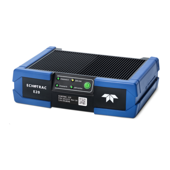
Echotrac E20
Singlebeam Echosounder
OPERATOR'S MANUAL
Version: 8
Teledyne Odom Hydrographic
Teledyne RESON A/S
Fabriksvangen 13
3550 Slangerup
Denmark
Telephone: +45 47 38 00 22
Fax: +45 47 38 00 66
www.teledynemarine.com/odom-hydrographic/
Number of pages: 60
Date: 25 November 2020
Use and Disclosure of Data
EU Uncontrolled Technology:
Information contained herein is uncontrolled under the E.U. Regulation (EC) No 428/2009.
However, export, reexport or diversion contrary to law is prohibited.
Advertisement
Table of Contents

Related Manuals for Teledyne Echotrac E20


Summary of Contents for Teledyne Echotrac E20
- Page 1 Echotrac E20 Singlebeam Echosounder OPERATOR'S MANUAL Version: 8 Teledyne Odom Hydrographic Teledyne RESON A/S Fabriksvangen 13 3550 Slangerup Denmark Telephone: +45 47 38 00 22 Fax: +45 47 38 00 66 www.teledynemarine.com/odom-hydrographic/ Number of pages: 60 Date: 25 November 2020...
- Page 2 A.2: Drawing of cable assy PARTD20639 added. Part numbers added to table and below drawings. 25 Mar 2019 Initial release © TELEDYNE RESON A/S 2019-2020 All rights are reserved. Reproduction in whole or in part is prohibited without the prior written consent of the copyright owner.
-
Page 3: Table Of Contents
Transducer Configuration ....................26 4.4.2 Auxiliary Sensors ......................27 4.4.3 Time Synchronization ....................27 Operation ............................29 Get Started..........................29 Operation Modes ........................29 Echotrac E20 Operator's Manual8 p. 3 of 60 November 25, 2020 Version 8 Uncontrolled Technology Subject to Restrictions Contained on the Cover Page. - Page 4 6.3.6 Air Bubbles........................36 6.3.7 Environment........................36 Troubleshooting ..........................37 The Echotrac E20 does not seem to be working ..............37 The Echotrac E20 power LED is off..................37 What are the COM port settings? ..................37 Known problems with Transducer..................37 Handling and Maintenance ......................38 Echotrac E20 .........................38 8.1.1...
- Page 5 Returning Goods for Service....................58 FIGURES Figure 1: Echotrac E20 Singlebeam Echosounder System..............11 Figure 2: Echotrac E20 Singlebeam Echosounder System Configuration ..........11 Figure 3: E20 depth performance ......................14 Figure 4: Echotrac E20 – Cooling......................21 Figure 5: Echotrac E20 rear panel cable connections ................22 Figure 6: Transducer mounted through the hull..................24...
- Page 6 Table 5: Supported auxiliary sensors ....................17 Table 6: Echotrac E20 rear panel cable connections ................22 Table 7: BITE icons ..........................33 Table 8: WPFDXInterop – Copyright Information ................47 Table 9: DirectXTK – Copyright Information ..................47 Table 10: Json.NET – Copyright Information ..................47 Table 11: mvvmlight –...
-
Page 7: Preface
PREFACE This Operator's Manual provides detailed procedures for the correct installation, operation, and maintenance of the Echotrac E20 Singlebeam Echosounder system. Before the system is operated for the first time, it is recommended that users familiarize themselves with the contents of this manual to ensure optimal system performance. - Page 8 Sound Velocity Probe SYNC synchronization To Be Defined Time Varied Gain transmitter user interface volts direct current Echotrac E20 Operator's Manual8 p. 8 of 60 November 25, 2020 Version 8 Uncontrolled Technology Subject to Restrictions Contained on the Cover Page.
-
Page 9: Inventory
(7/8“ connector 5 pole male, e.g. GT272254-32050) 1012767-DK Cable Assy,DustCap Plastic for 7/8 male end with cord, 120mm 1013728-DK Memory stick, USB - for manuals and SW, Echotrac E20 1013740-DK Quick Reference Guide, Echotrac E20 1013832-DK Quick Start Guide, SBES User Interface... -
Page 11: Introduction
INTRODUCTION System Overview The Echotrac E20 Singlebeam Echosounder is a dual or single-channel echosounder. The Echotrac E20 is addressing the need for a more compact echosounder for classical day-to-day hydrography on a vessel of opportunity or as a fixed installation on a survey boat. The system is portable, ruggedized, and watertight. -
Page 12: Main Features
INTRODUCTION Main Features Bottom detection: The Echotrac E20 provides the most reliable and robust bottom tracking available for precise and repeatable survey results. Its bottom tracking algorithms are based on our multibeam and singlebeam experience and relies on the proven technology from SeaBat, Echotrac, ParaSound, and HydroSweep sonars. -
Page 13: Product Description
Complies with standard EN 60945 $ 8.6 The E20 single channel can utilize both channels, but not at the same time. External AC power is for dry installation (not IP67 compliant). Echotrac E20 Operator's Manual8 p. 13 of 60 November 25, 2020 Version 8 Uncontrolled Technology Subject to Restrictions Contained on the Cover Page. -
Page 14: Performance
The depth values are based on the performance of TC2122 for 200 and 33kHz, and HM210/12-8/20 for 12kHz. Stated depth ranges may be impacted by environmental conditions, vessel installation, and motion Echotrac E20 Operator's Manual8 p. 14 of 60 November 25, 2020 Version 8 Uncontrolled Technology Subject to Restrictions Contained on the Cover Page. -
Page 15: Standard Data Products
Standard Data Products 2.3.1 Depth Output via Serial or UDP Port The Echotrac E20 is capable of generating ASCII depth data messages via serial or UDP port COM3. The following depth data messages are supported by the Echotrac E20: Depth ... -
Page 16: Supported Transducers
PRODUCT DESCRIPTION 2.3.3 Supported Transducers The Echotrac E20 can generally be adapted to a wide range of transducers. Performance and features of the singlebeam echosounder depends on the selected transducer. The selectable transducers are listed in Table 4. For installation, see section 4.3 Transducer Installation. -
Page 17: Supported Auxiliary Sensors
OCTANS TAH Up to 10Hz sample rate Up to 50Hz sample rate Only the heave component is used by the E20. Echotrac E20 Operator's Manual8 p. 17 of 60 November 25, 2020 Version 8 Uncontrolled Technology Subject to Restrictions Contained on the Cover Page. -
Page 18: Ce Marking
PRODUCT DESCRIPTION CE Marking Echotrac E20 Operator's Manual8 p. 18 of 60 November 25, 2020 Version 8 Uncontrolled Technology Subject to Restrictions Contained on the Cover Page. -
Page 19: Safety Precautions
(see Appendix E – Warranty Information). Operator Safety The Echotrac E20 system should be handled with attention to operator safety as well as protection of the hardware components. General precautions include: Do not connect or disconnect cables with the power on. -
Page 20: Safe Disposal Of Waste (Weee Directive)
For more details about the recycling of this product, please contact your local authority, your household waste disposal service provider, or Customer Support at reson-support@teledyne.com. Echotrac E20 Operator's Manual8 p. -
Page 21: Installation
INSTALLATION Echotrac E20 Mounting The Echotrac E20 is a flexible unit designed for tabletop or rack mounting. The outer cabinet of the Echotrac E20 is covered with EPDM rubber, which protects the unit from small bumps etc. and gives the unit a non-slip surface. -
Page 22: Echotrac E20
Echotrac E20. Do not disconnect any cables from the rear of the Echotrac E20 while the unit is running. This can damage the internal workings of the unit. -
Page 23: Front Panel
Do not pull out the cables with the power on. 4.2.2 Front Panel The power button and BITE LEDs are located on the front of the Echotrac E20. Power button: A short push enters/exits standby. -
Page 24: Transducer Installation
Care should be taken to protect the transducer from damage. The installation of a fairing will contribute to reducing the risk of impact damage. Echotrac E20 Operator's Manual8 p. 24 of 60 November 25, 2020 Version 8 Uncontrolled Technology Subject to Restrictions Contained on the Cover Page. -
Page 25: Hull Mount
Figure 7: Transducer mounted over the side Care should be taken to assure adequate protection for the transducer cable, particularly at the point where the cable leaves the transducer body. Echotrac E20 Operator's Manual8 p. 25 of 60 November 25, 2020 Version 8 Uncontrolled Technology Subject to Restrictions Contained on the Cover Page. -
Page 26: Configuration In Sbes Ui
UI PC time are the supported options. See 4.4.3 below. When selecting one of the generic “unknown” transducers, range performance suffers, as max. power has been reduced for precautionary purposes. Echotrac E20 Operator's Manual8 p. 26 of 60 November 25, 2020 Version 8... -
Page 27: Auxiliary Sensors
Use an NTP Server. The active source is indicated with a Use a GPS receiver with PPS output. green icon. Echotrac E20 Operator's Manual8 p. 27 of 60 November 25, 2020 Version 8 Uncontrolled Technology Subject to Restrictions Contained on the Cover Page. - Page 28 (f) Wait a few minutes for time to synchronize. Time synchronization of E20 to the UI PC only works, if there is no firewall or routing rules that prevent the underlying UDP connection. Echotrac E20 Operator's Manual8 p. 28 of 60 November 25, 2020 Version 8 Uncontrolled Technology Subject to Restrictions Contained on the Cover Page.
-
Page 29: Operation
(see section 5.2 below), and then the pinging starts. Operation Modes The Echotrac E20 is an extremely robust and reliable hydrographic echosounder. Its main operation parameters may be maintained autonomously (fully or partially) or manually. Figure 8: Operation modes Echotrac E20 Operator's Manual8 p. -
Page 30: Mobilize Modes
The gates are only visible and interactive when the depth line for the given channel is on. The gates option is NOT available in any of the survey modes (see section 5.2.2 below). Echotrac E20 Operator's Manual8 p. 30 of 60... -
Page 31: Survey Modes
When desired, all parameters may be adjusted by the operator. The scale settings are adjusted in predetermined increments. Echotrac E20 Operator's Manual8 p. 31 of 60 November 25, 2020 Version 8 Uncontrolled Technology Subject to Restrictions Contained on the Cover Page. -
Page 32: Standalone Operation
Make sure to switch off the E20, when it is not used. It will continue pinging, if you have not explicitly disabled pinging in the UI before closing it. Echotrac E20 Operator's Manual8 p. 32 of 60 November 25, 2020 Version 8 Uncontrolled Technology Subject to Restrictions Contained on the Cover Page. -
Page 33: Sbes Ui Bite
A time source is active, but no data is received, or the data contains a large time jump. If you are confident there is no error, the time sync can be restarted by toggling the source in the UI. Echotrac E20 Operator's Manual8 p. 33 of 60 November 25, 2020 Version 8 Uncontrolled Technology Subject to Restrictions Contained on the Cover Page. -
Page 34: The Echotrac E20 In Action
THE ECHOTRAC E20 IN ACTION THE ECHOTRAC E20 IN ACTION Survey Operation Modes For most applications, the Automatic mode is the optimal choice for the E20 to deliver the best data, in the widest variety of seafloor conditions, as it constantly adapts to the signal received. Should the operator or hydrographic surveyor desire full control of the sonar, the manual mode provides this facility. -
Page 35: Interference Considerations
Physical limitations in the functionality of the system must be taken into consideration when installing and operating echosounders, including the Echotrac E20. Some of the limitations are absolutes; others can be overcome to some degree. The following subsections provide examples of different kinds of limitations. -
Page 36: Interference From Other Echosounder Systems
Echotrac E20 system. The most typical source of interference of this type is navigational sonars (often 50kHz systems) and Doppler velocity logs. -
Page 37: Troubleshooting
If the Echotrac E20 does not seem to be working correctly, perform these steps to find the cause. (a) Check if the power LED is on. (b) The Echotrac E20 has a Standby bit that is turned on by default. Try to communicate with the Echotrac E20 via the SBES UI. -
Page 38: Handling And Maintenance
8.1.3 System Tool – E20 Software Update The E20 System Tool allows you to manage the Echotrac E20 echosounder. The tool is provided on the USB key delivered with your system. Install System Tool... - Page 39 Static IP (c) Click Apply. (d) The E20 is automatically rebooted for the settings to take effect. Echotrac E20 Operator's Manual8 p. 39 of 60 November 25, 2020 Version 8 Uncontrolled Technology Subject to Restrictions Contained on the Cover Page.
-
Page 40: Recovery
Recovery mode is for trained engineering service personnel. It is a safe mode that allows access to the E20 on a secondary recovery IP address. The main user settings are still active. You can force the Echotrac E20 echosounder into Recovery mode by pressing the Channel A and B buttons simultaneously at power up. -
Page 41: Maintenance
Lubricate the connectors lightly with 3M lubricating spray or equivalent when necessary. Grip main body of connector during mating or unmating. Do not pull on cable to disconnect. Avoid sharp bends at cable entry to connector. Echotrac E20 Operator's Manual8 p. 41 of 60 November 25, 2020 Version 8 Uncontrolled Technology Subject to Restrictions Contained on the Cover Page. -
Page 42: Appendix A - Reference Documentation
Format (.pdf) for printing. Document Title Document Number Description Echotrac E20 Operator's Manual OM19133 Version 7 or higher Echotrac E20 Quick Reference Guide QG19389 Version 4 or higher SBES User Interface Quick Start Guide QG19897 Version 1 or higher Data Format Definition Document DFD20723 (NEW no.) -
Page 43: Figure 12: Echotrac E20 Outline
REFERENCE DOCUMENTATION Figure 12: Echotrac E20 outline Echotrac E20 Operator's Manual p. 43 of 60 November 25, 2020 Version 8 Uncontrolled Technology Subject to Restrictions Contained on the Cover Page. -
Page 44: Figure 13: Serial Cable (Pn 1014481-Dk)
REFERENCE DOCUMENTATION Figure 13: Serial cable (PN 1014481-DK) Echotrac E20 Operator's Manual p. 44 of 60 November 25, 2020 Version 8 Uncontrolled Technology Subject to Restrictions Contained on the Cover Page. -
Page 45: Figure 14: Converter Transducer Cable (Optional Component, Pn 1013713-Dk)
REFERENCE DOCUMENTATION Figure 14: Converter transducer cable (optional component, PN 1013713-DK) Echotrac E20 Operator's Manual p. 45 of 60 November 25, 2020 Version 8 Uncontrolled Technology Subject to Restrictions Contained on the Cover Page. -
Page 46: Figure 15: Extender Transducer Cable (Optional Component, Pn 1013700-Dk)
REFERENCE DOCUMENTATION Figure 15: Extender transducer cable (optional component, PN 1013700-DK) Echotrac E20 Operator's Manual p. 46 of 60 November 25, 2020 Version 8 Uncontrolled Technology Subject to Restrictions Contained on the Cover Page. -
Page 47: Licenses - Copyright Information
The above copyright notice and this permission notice shall be included in all copies or substantial portions of the Software. Echotrac E20 Operator's Manual p. 47 of 60 November 25, 2020 Version 8 Uncontrolled Technology Subject to Restrictions Contained on the Cover Page. -
Page 48: Table 12: Sharpavi - Copyright Information
The above copyright notice and this permission notice shall be included in all copies or substantial portions of the Software. Echotrac E20 Operator's Manual p. 48 of 60 November 25, 2020 Version 8 Uncontrolled Technology Subject to Restrictions Contained on the Cover Page. -
Page 49: Appendix B - Cable Connectors
Shield SYNC Signal Trig out Trig in/out GND PPS in Shield Power Signal Protection Earth (chassis) 10-30VDC Echotrac E20 Operator's Manual p. 49 of 60 November 25, 2020 Version 8 Uncontrolled Technology Subject to Restrictions Contained on the Cover Page. -
Page 50: Lan
CABLE CONNECTORS Signal Echotrac E20 Operator's Manual p. 50 of 60 November 25, 2020 Version 8 Uncontrolled Technology Subject to Restrictions Contained on the Cover Page. -
Page 51: Appendix C - Serial And Udp Output String Formats
30 Mar 2019 at 20:59:59.999 PPS synchronized, depth of 123.999m corrected for heave for channel A at -216.14dB and 0.950m draft, depth of 124.321m corrected for heave for channel B at -218.14dB and 1.100m draft, -2.230m heave, sound velocity 1435.98m/s Echotrac E20 Operator's Manual p. 51 of 60 November 25, 2020 Version 8 Uncontrolled Technology Subject to Restrictions Contained on the Cover Page. -
Page 52: Echotrac Sbt (For Depth)
Depth data Depth data Depth data Depth data (LSD) Carriage return Example: <sp>ETOL<sp>DDDDD<CR> <sp>ETOL<sp>54321<CR> Low freq. error, 54321dft Echotrac E20 Operator's Manual p. 52 of 60 November 25, 2020 Version 8 Uncontrolled Technology Subject to Restrictions Contained on the Cover Page. -
Page 53: Deso25 (For Depth)
Unit indicator: “m” = meters, “t” = feet Carriage return Line feed Example: DBDDDDDDDD<sp>m<CR><LF> DB20.00665<sp>m<CR><LF> or DB684.9470ft<CR><LF> Low freq., 20.00665 meters or DB684.9470 feet Echotrac E20 Operator's Manual p. 53 of 60 November 25, 2020 Version 8 Uncontrolled Technology Subject to Restrictions Contained on the Cover Page. -
Page 54: Nmea 0183 (For Depth)
Period Heave data decimal <sp> Space meters Carriage return Line feed Example: DHDD.DD<sp>m<CR><LF> DH-2.00<sp>m<CR><LF> Heave, -2.00 meters Echotrac E20 Operator's Manual p. 54 of 60 November 25, 2020 Version 8 Uncontrolled Technology Subject to Restrictions Contained on the Cover Page. -
Page 55: Table 21: Deso Ddv Draft
10-12 meters per second Carriage return Line feed Example: CSDDDD<sp>m/s<CR><LF> CS1500<sp>m/s<CR><LF> Sound velocity 1500 meters per second Echotrac E20 Operator's Manual p. 55 of 60 November 25, 2020 Version 8 Uncontrolled Technology Subject to Restrictions Contained on the Cover Page. -
Page 56: Appendix D - System Options
SYSTEM OPTIONS APPENDIX D – SYSTEM OPTIONS The following options are available with the Echotrac E20 system. If you require more details about any of these options, please contact Teledyne Marine for assistance. Extended Warranty Contract Additional Serial Connectors Additional Transducer Connectors... -
Page 57: Appendix E - Warranty Information
Teledyne Marine will, at its option, either repair or replace components that prove to be defective. The warranty period begins on the day the system is accepted by the customer. Your Teledyne Odom Hydrographic system must be serviced by the Teledyne Marine office that sold it. The customer shall prepay shipping charges (and shall pay all duty and taxes) for products returned for service. -
Page 58: Appendix F - Support And Service
No goods may be returned without prior authorization, as evidenced by a Return Authorization (RMA) Number. Before returning any equipment for service, you must follow the Teledyne RESON equipment return procedure stated below: (a) Contact a Teledyne RESON office to obtain an approved Return Material Authorization (RMA) number. - Page 60 Echotrac E20 Operator's Manual Document Number: OM19133-8 Part Number: 1013460...
Need help?
Do you have a question about the Echotrac E20 and is the answer not in the manual?
Questions and answers