Omron ACCURAX G5 User Manual
Accurax g5 servo system with analogue/pulse control; servo drives/servomotors
Hide thumbs
Also See for ACCURAX G5:
- Datasheet (20 pages) ,
- Quick start manual (13 pages) ,
- User manual (458 pages)

Related Manuals for Omron ACCURAX G5


Summary of Contents for Omron ACCURAX G5
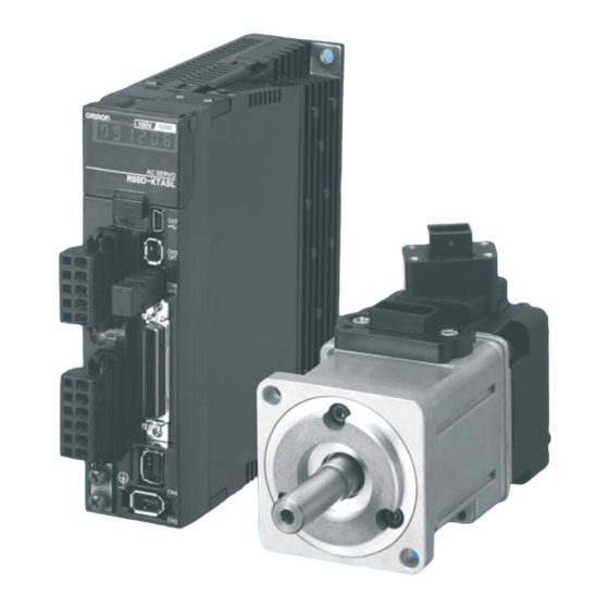
- Page 1 Cat. No. I571-E2-01 Accurax G5 servo system with Analogue/Pulse control Model: R88D-KT_ Servo Drives R88M-K_ Servomotors USER’S MANUAL...
- Page 3 Before using the Accurax G5, read through this manual and gain a full understanding of the information provided herein. After you finished reading the manual, keep it in a convenient place so that the manual can be referenced at any time.
- Page 4 Items Requiring Acknowledgment 1. Terms of Warranty (1) Warranty period The warranty period of this product is 1 year after its purchase or delivery to the specified location. (2) Scope of warranty If the product fails during the above warranty period due to design, material or workmanship, we will provide a replacement unit or repair the faulty product free of charge at the location where you purchased the product.
- Page 5 Items Requiring Acknowledgment such a way to notify dangers or ensure the necessary level of safety via design redundancy, and that the product is wired and installed appropriately in the system according to the intended application. (4) Sample applications explained in the catalog, etc. are provided for reference purposes only.
-
Page 6: Safety Precautions Document
So that the Accurax G5 Servomotor and Servo Drive and peripheral equipment are used safely and correctly, be sure to peruse this Safety Precautions document section and the main text before using the product in order to learn all items you should know regarding the equipment as well as all safety information and precautions. - Page 7 Illustrations contained in this manual sometimes depict conditions without covers and safety shields for the purpose of showing the details. When using this product, be sure to install the covers and shields as specified and use the product according to this manual.
- Page 8 Fire or failure may result. Do not perform wiring or any operation with wet hands. Electric shock, injury or fire may result. Do not touch the key grooves with bare hands if a motor with shaft-end key grooves is being used. Injury may result.
-
Page 9: Storage And Transportation
Safety Precautions Document Storage and Transportation Caution When transporting the product, do not hold it by the cables or motor shaft. Injury or failure may result. Do not overload the products. (Follow the instruction on the product label.) Injury or failure may result. - Page 10 Caution Do not step on the product or place heavy articles on it. Injury may result. Do not block the intake or exhaust openings. Do not allow foreign objects to enter the product. Fire may result. Be sure to observe the mounting direction.
- Page 11 Separate the motor from the mechanical system and check its operation before installing the motor to the machine. Injury may result. If an alarm generated, remove the cause of the alarm and ensure safety, and then reset the alarm and restart the operation. Injury may result.
-
Page 12: Maintenance And Inspection
Equipment damage may result. Never repair the product by disassembling it. Electric shock or injury may result. Be sure to turn OFF the power supply when the unit is not going to be used for a prolonged period of time. Injury may result. - Page 13 (R88D-KTA5L) Instructions on Warning Label Disposal When disposing of the battery, insulate it using tape, etc. and dispose of it by following the applicable ordinance of your local government. Dispose of the product as an industrial waste. Accurax G5 AC SERVOMOTOR AND SERVO DRIVE USER'S MANUAL...
-
Page 14: Items To Check After Unpacking
Connectors, mounting screws, etc. other than those in the table below are not supplied. They must be prepared by the customer. If any item is missing or a problem is found such as Servo Drive damage, contact the OMRON dealer or sales office where you purchased your product. -
Page 15: Manual Revision History
Manual Revision History Manual Revision History The manual revision symbol is an alphabet appended at the end of the manual number found in the bottom left-hand corner of the front or back cover. Example I571-E2-01 Revision symbol Revision Revision date... -
Page 16: Structure Of This Document
This manual consists of the following chapters. Read the necessary chapter or chapters referring to below. Outline Features and This chapter explains the features of this product, name of each part, Chapter 1 System and applicable EC directives and UL standards. - Page 17 Accurax G5 AC SERVOMOTOR AND SERVO DRIVE USER'S MANUAL...
-
Page 18: Table Of Contents
Regenerative Energy Absorption............4-36 Chapter5 BASIC CONTROL Mode Position Control .................. 5-2 Speed Control..................5-8 Torque Control..................5-14 Internally Set Speed Control............... 5-19 Switching Control................5-22 Full Closing Control ................5-25 Accurax G5 AC SERVOMOTOR AND SERVO DRIVE USER'S MANUAL... - Page 19 Gain Switching 3 Function..............6-33 Torque Limit..................6-34 6-10 Sequence I/O Signal................6-37 6-11 Forward and Reverse Drive Prohibition Functions ......6-43 6-12 Disturbance Observer Function............6-46 6-13 Friction Torque Compensation Function ..........6-48 6-14 Inertia Ratio Switching Function ............6-50 6-15 Hybrid Vibration Suppression Function ..........
- Page 20 11-2 Warning List..................11-5 11-3 Alarm List.................... 11-6 11-4 Troubleshooting.................. 11-11 11-5 Periodic Maintenance ................. 11-22 Chapter12 Appendix 12-1 Connection Examples................. 12-2 12-2 Parameter List ..................12-12 12-3 Safety Certification ................12-33 Index Accurax G5 AC SERVOMOTOR AND SERVO DRIVE USER'S MANUAL...
- Page 21 Features and System Configuration This chapter explains the features of this product, name of each part, and applicable EC directives and UL standards. 1-1 Outline ................1-2 Outline of the Accurax G5............... 1-2 Features of the Accurax G5 ............1-2 1-2 System Configuration ..........1-3 1-3 Names and Functions ..........1-4...
-
Page 22: Outline
Safe Torque OFF (STO) Function to Ensure Safety You can cut off the motor current to stop the motor based on a signal from an immediate stop button or other safety equipment. In addition to the conventional stop method based on a control signal, the STO function that permits direct stopping without a need to involve the control circuit provides the immediate stop from 2 systems, thereby enhancing safety. -
Page 23: System Configuration
Analog voltage Programmable Motion Control Unit Controller CS1W-MC221/421 (-V1) SYSMAC CS 'Accurax G5 AC Servomotor Pulse R88D-KTx train SYSMAC + Position Control Unit (Pulse Train Output Type) NC41 4 SYNC ERC ERH PA202 POWER SYSMAC CJ1G-CPU44 ERR/ALM PROGRAMMABLE PRPHL CONTROLLER... -
Page 24: Names And Functions
Charge lamp Control I/O connector (CN1) External Regeneration Resistor connection terminals (B1, B2 and B3) Motor connection terminals (U, V and W) External scale connector (CN4) Protective ground terminals Encoder connector (CN2) Accurax G5 AC SERVOMOTOR AND SERVO DRIVE USER'S MANUAL... -
Page 25: Driver Functions
1-3 Names and Functions Driver Functions Display Area A 6-digit 7-segment LED display shows the driver status, alarm codes, parameters, and other information. Operation Area Monitors the parameter setting and driver condition. Charge Lamp Lits when the main circuit power supply is turned ON. -
Page 26: System Block Diagrams
MPU&ASIC 1.5 V control power area E5 V supply Position, speed and torque calculation control area ±12 V • PWM control Control Encoder External Analog Safety interface scale monitor Accurax G5 AC SERVOMOTOR AND SERVO DRIVE USER'S MANUAL... - Page 27 MPU&ASIC 1.5 V control power area E5 V supply Position, speed and torque calculation control area ±12 V • PWM control Cooling fan Control Encoder External Analog Safety interface scale monitor Accurax G5 AC SERVOMOTOR AND SERVO DRIVE USER'S MANUAL...
- Page 28 MPU&ASIC 1.5 V control power area E5 V supply Position, speed and torque calculation control area ±12 V • PWM control Cooling fan External Analog Control Encoder Safety interface scale monitor Accurax G5 AC SERVOMOTOR AND SERVO DRIVE USER'S MANUAL...
- Page 29 MPU&ASIC 1.5 V control power area E5 V supply Position, speed and torque calculation control area ±12 V • PWM control Cooling fan Control Encoder External Analog Safety interface scale monitor Accurax G5 AC SERVOMOTOR AND SERVO DRIVE USER'S MANUAL...
- Page 30 1.5 V control power area E5 V supply Position, speed and torque calculation control area ±12 V • PWM control Cooling fan Control Encoder External Analog Safety interface scale monitor Accurax G5 AC SERVOMOTOR AND SERVO DRIVE USER'S MANUAL 1-10...
-
Page 31: Applicable Standards
EN 55011 class A group 1 directives AC Servomotor IEC61800-3 EN61000-6-2 Note. To conform to EMC directives, the Servo Motor and Servo Drive must be installed under the conditions described in "4-3 Wiring Conforming to EMC Directives" (P.4-22). UL and cUL Standards Standard Product... - Page 33 Standard Models and External Dimensions This chapter explains the models of Servo Drive, Servomotor, and peripheral equipment, as well as the external dimensions and mounting dimensions. 2-1 Servo System Configuration ........2-2 2-2 How to Read Model............2-4 Servo Drive ..................2-4 Servomotor ..................
-
Page 34: Servo System Configuration
SYSMAC + Controller (Analog output type) Control Cables (for Motion Control Unit) R88A-CPG Analog Commands/Feedback Signals Programmable Controller SYSMAC CS1 Motion Control Unit (MC) CS1W-MC221/421 (-V1) Available to build the Absolute System. Accurax G5 AC SERVOMOTOR AND SERVO DRIVE USER'S MANUAL... - Page 35 R88A-CRGD0R3C (-BS) (A battery is included with External model numbers ending in “BS”). Regeneration External encoder Resistors R88A-RR * Not required if a battery is connected to the control connector (CN1). Accurax G5 AC SERVOMOTOR AND SERVO DRIVE USER'S MANUAL...
-
Page 36: How To Read Model
2-2 How to Read Model 2-2 How to Read Model Servo Drive The Servo Drive model can be identified by the Servo Drive type, applicable Servomotor capacity, power supply voltage, etc. R88D-KT01H Accurax G5 Series Servomotor Driver Type : Pulse/analog type... -
Page 37: Servomotor
: 400 VAC (absolute encoder specifications) : 200 VAC (absolute encoder specifications) : 100 VAC (absolute encoder specifications) Options Blank : Straight shaft, no key : With brake : With oil seal : Straight, key, tapped Accurax G5 AC SERVOMOTOR AND SERVO DRIVE USER'S MANUAL... -
Page 38: Standard Model List
3-phase 200 VAC 2 kW R88D-KT20H 3 kW R88D-KT30H 5 kW R88D-KT50H 3-phase 400 VAC 600 W R88D-KT06F 1 kW R88D-KT10F 1.5 kW R88D-KT15F 2 kW R88D-KT20F 3 kW R88D-KT30F 5 kW R88D-KT50F Accurax G5 AC SERVOMOTOR AND SERVO DRIVE USER'S MANUAL... -
Page 39: Servomotor Model List
1.5 kW R88M-K1K530F R88M-K1K530F-S2 R88M-K1K530C R88M-K1K530C-S2 400 V 2 kW R88M-K2K030F R88M-K2K030F-S2 R88M-K2K030C R88M-K2K030C-S2 3 kW R88M-K3K030F R88M-K3K030F-S2 R88M-K3K030C R88M-K3K030C-S2 4 kW R88M-K4K030F R88M-K4K030F-S2 R88M-K4K030C R88M-K4K030C-S2 5 kW R88M-K5K030F R88M-K5K030F-S2 R88M-K5K030C R88M-K5K030C-S2 Accurax G5 AC SERVOMOTOR AND SERVO DRIVE USER'S MANUAL... - Page 40 2 kW R88M-K2K030F-B R88M-K2K030F-BS2 R88M-K2K030C-B R88M-K2K030C-BS2 3 kW R88M-K3K030F-B R88M-K3K030F-BS2 R88M-K3K030C-B R88M-K3K030C-BS2 4 kW R88M-K4K030F-B R88M-K4K030F-BS2 R88M-K4K030C-B R88M-K4K030C-BS2 5 kW R88M-K5K030F-B R88M-K5K030F-BS2 R88M-K5K030C-B R88M-K5K030C-BS2 Note. Models with oil seals are also available. Accurax G5 AC SERVOMOTOR AND SERVO DRIVE USER'S MANUAL...
- Page 41 2 kW R88M-K2K020F-B R88M-K2K020F-BS2 R88M-K2K020C-B R88M-K2K020C-BS2 3 kW R88M-K3K020F-B R88M-K3K020F-BS2 R88M-K3K020C-B R88M-K3K020C-BS2 4 kW R88M-K4K020F-B R88M-K4K020F-BS2 R88M-K4K020C-B R88M-K4K020C-BS2 5 kW R88M-K5K020F-B R88M-K5K020F-BS2 R88M-K5K020C-B R88M-K5K020C-BS2 Note. Models with oil seals are also available. Accurax G5 AC SERVOMOTOR AND SERVO DRIVE USER'S MANUAL...
- Page 42 R88M-K3K010T-B R88M-K3K010T-BS2 900 kW R88M-K90010F-B R88M-K90010F-BS2 R88M-K90010C-B R88M-K90010C-BS2 400 V 2 kW R88M-K2K010F-B R88M-K2K010F-BS2 R88M-K2K010C-B R88M-K2K010C-BS2 3 kW R88M-K3K010F-B R88M-K3K010F-BS2 R88M-K3K010C-B R88M-K3K010C-BS2 Note. Models with oil seals are also available. 2-10 Accurax G5 AC SERVOMOTOR AND SERVO DRIVE USER'S MANUAL...
-
Page 43: Servo Drive And Servomotor Combination List
The tables in this section show the possible combinations of Accurax G5 Servo Drives and Servomotors. The Servomotors and Servo Drives can only be used in the listed combinations. -x at the end of the motor model number is for options, such as the shaft type, brake, oil seal and key. - Page 44 200 V 3 kW R88M-K3K010H-x R88M-K3K010T-x R88D-KT50H Single- phase/3- 900 W R88M-K90010F-x R88M-K90010C-x R88D-KT15F phase 400 V 2 kW R88M-K2K010F-x R88M-K2K010C-x R88D-KT30F 3-phase 400 V 3 kW R88M-K3K010F-x R88M-K3K010C-x R88D-KT50F 2-12 Accurax G5 AC SERVOMOTOR AND SERVO DRIVE USER'S MANUAL...
-
Page 45: Peripheral Equipment And Cable Model List
(for both absolute encoders and incremental encoders) 10 m R88A-CRKC010NR-E [400 V] 15 m R88A-CRKC015NR-E For 3,000-r/min motors For 2,000-r/min motors 20 m R88A-CRKC020NR-E For 1,000-r/min motors (for both absolute encoders and incremental encoders) Accurax G5 AC SERVOMOTOR AND SERVO DRIVE USER'S MANUAL 2-13... - Page 46 For 1,000-r/min motors of 2 to 3 kW R88A-CAGD005SR-E R88A-CAGD005BR-E 10 m R88A-CAGD010SR-E R88A-CAGD010BR-E 15 m R88A-CAGD015SR-E R88A-CAGD015BR-E 20 m R88A-CAGD020SR-E R88A-CAGD020BR-E Note: For the separate brake cable selection, see brake cables table in page 2-15 2-14 Accurax G5 AC SERVOMOTOR AND SERVO DRIVE USER'S MANUAL...
- Page 47 [400 V] 20 m R88A-CRKC020N For 3,000-r/min motors 30 m R88A-CRKC030N For 2,000-r/min motors For 1,000-r/min motors 40 m R88A-CRKC040N (for both absolute encoders and incremental encoders) 50 m R88A-CRKC050N Accurax G5 AC SERVOMOTOR AND SERVO DRIVE USER'S MANUAL 2-15...
- Page 48 20 m R88A-CAGD020S R88A-CAGD020B 30 m R88A-CAGD030S R88A-CAGD030B 40 m R88A-CAGD040S R88A-CAGD040B 50 m R88A-CAGD050S R88A-CAGD050B Note: For the separate brake cable selection, see brake cables table in page 2-16 2-16 Accurax G5 AC SERVOMOTOR AND SERVO DRIVE USER'S MANUAL...
- Page 49 [400 V] 20 m R88A-CRKC020NR For 3,000-r/min motors 30 m R88A-CRKC030NR For 2,000-r/min motors For 1,000-r/min motors 40 m R88A-CRKC040NR (for both absolute encoders and incremental encoders) 50 m R88A-CRKC050NR Accurax G5 AC SERVOMOTOR AND SERVO DRIVE USER'S MANUAL 2-17...
- Page 50 20 m R88A-CAGD020SR R88A-CAGD020BR 30 m R88A-CAGD030SR R88A-CAGD030BR 40 m R88A-CAGD040SR R88A-CAGD040BR 50 m R88A-CAGD050SR R88A-CAGD050BR Note: For the separate brake cable selection, see brake cables table in page 2-18 2-18 Accurax G5 AC SERVOMOTOR AND SERVO DRIVE USER'S MANUAL...
- Page 51 ABS battery cable (R88A-BAT01G battery × 1 supplied) 0.3 m R88A-CRGD0R3C-BS Analog Monitor Cable Specifications Model Analog monitor cable R88A-CMK001S Absolute Encoder Backup Battery Specifications Model 2,000 mA•h 3.6 V R88A-BAT01G Accurax G5 AC SERVOMOTOR AND SERVO DRIVE USER'S MANUAL 2-19...
- Page 52 R88A-CNU11C Encoder connector (CN2) R88A-CNW01R External encoder connector (CN4) R88A-CNK41L Safety connector (CN8) R88A-CNK81S Power cable connector (for 750 W max.) R88A-CNK11A Brake cable connector (for 750 W max.) R88A-CNK11B 2-20 Accurax G5 AC SERVOMOTOR AND SERVO DRIVE USER'S MANUAL...
-
Page 53: Servo Relay Unit Cables For Servo Drives
Servo Relay Unit Cables for Servo Drives Specifications Model Servo Drive cables For CS1W-NC113/-NC133, CJ1W-NC113/- XW2Z-100J-B25 NC133, C200HW-NC113 (XW2B-20J6-1B) XW2Z-200J-B25 For CS1W-NC213/-NC413/-NC233/-NC433, CJ1W-NC213/-NC413/-NC233/-NC433, C200HW-NC213/-NC413 (XW2B-40J6-2B) For CQM1-CPU43-V1 or CQM1H-PLB21 (XW2B-20J6-3B) For CJM1-CPU21/-CPU22/-CPU23 XW2Z-100J-B31 (XW2B-20J6-8A/XW2B-40J6-9A) XW2Z-200J-B31 Accurax G5 AC SERVOMOTOR AND SERVO DRIVE USER'S MANUAL 2-21... -
Page 54: Servo Relay Unit Cables For Position Control Units
XW2Z-100J-A14 For CJ1W-NC213/-NC413 (XW2B-20J6-2B) 0.5 m XW2Z-050J-A15 XW2Z-100J-A15 For CJ1W-NC133 (XW2B-20J6-1B) 0.5 m XW2Z-050J-A18 XW2Z-100J-A18 For CJ1W-NC233/-NC433 (XW2B-20J6-2B) 0.5 m XW2Z-050J-A19 XW2Z-100J-A19 For CJ1M-CPU21/-CPU22/-CPU23 (XW2B- 0.5 m XW2Z-050J-A33 20J6-8A/XW2B-40J6-9A) XW2Z-100J-A33 2-22 Accurax G5 AC SERVOMOTOR AND SERVO DRIVE USER'S MANUAL... - Page 55 External Regeneration Resistors Specifications Model Regeneration process capacity: 20 W, 50 Ω (with 150°C thermal sensor) R88A-RR08050S Regeneration process capacity: 20 W, 100 Ω (with 150°C thermal sensor) R88A-RR080100S Regeneration process capacity: 70 W, 47 Ω (with 170°C thermal sensor) R88A-RR22047S Regeneration process capacity: 180 W, 20 Ω...
- Page 56 2-3 Standard Model List Mounting Brackets (L-Brackets for Rack Mounting) Specifications Model R88D-KTA5L/-KT01L/-KT01H/-KT02H R88A-TK01K R88D-KT02L/-KT04H R88A-TK02K R88D-KT04L/-KT08H R88A-TK03K R88D-KT10H/-KT15H R88A-TK04K 2-24 Accurax G5 AC SERVOMOTOR AND SERVO DRIVE USER'S MANUAL...
-
Page 57: External And Mounting Dimensions
2-4 External and Mounting Dimensions Servo Drive Dimensions Single-phase 100 VAC: R88D-KTA5L/-KT01L (50 to 100 W) Single-phase/3-phase 200 VAC: R88D-KT01H/-KT02H (100 to 200 W) Wall Mounting External dimensions Mounting dimensions φ5.2 ±0.5 (40) Accurax G5 AC SERVOMOTOR AND SERVO DRIVE USER'S MANUAL 2-25... - Page 58 2-4 External and Mounting Dimensions Front Mounting (Using Front Mounting Brackets) External dimensions Mounting dimensions 19.5 φ5.2 φ5.2 Square hole (40) 2-26 Accurax G5 AC SERVOMOTOR AND SERVO DRIVE USER'S MANUAL...
- Page 59 2-4 External and Mounting Dimensions Wall Mounting External dimensions Mounting dimensions φ5.2 ±0.5 (55) Front Mounting (Using Front Mounting Brackets) External dimensions Mounting dimensions 19.5 φ5.2 φ5.2 Square hole R2.6 Accurax G5 AC SERVOMOTOR AND SERVO DRIVE USER'S MANUAL 2-27...
- Page 60 2-4 External and Mounting Dimensions Wall Mounting External dimensions Mounting dimensions φ5.2 ±0.5 (65) Front Mounting (Using Front Mounting Brackets) External dimensions Mounting dimensions 19.5 φ5.2 φ5.2 ±0.5 Square hole R2.6 2-28 Accurax G5 AC SERVOMOTOR AND SERVO DRIVE USER'S MANUAL...
- Page 61 2-4 External and Mounting Dimensions Single-phase/3-phase 200 VAC: R88D-KT10H/-KT15H (900 W to 1.5 kW) Wall Mounting External dimensions Mounting dimensions φ5.2 (85) ±0.5 Front Mounting (Using Front Mounting Brackets) External dimensions Mounting dimensions (86) 19.5 φ5.2 φ5.2 φ5.2 Square hole R2.6...
- Page 62 2-4 External and Mounting Dimensions 3-phase 200 VAC: R88D-KT20H (2 kW) Wall Mounting External dimensions (86) 193.5 17.5 φ5.2 42.5 R2.6 R2.6 R2.6 R2.6 φ5.2 42.5 17.5 Mounting dimensions ±0.5 φ5.2 ±0.5 17.5 (86) 2-30 Accurax G5 AC SERVOMOTOR AND SERVO DRIVE USER'S MANUAL...
- Page 63 2-4 External and Mounting Dimensions Front Mounting (Using Front Mounting Brackets) External dimensions (86) 193.5 17.5 φ5.2 42.5 30.7 R2.6 R2.6 R2.6 R2.6 φ5.2 42.5 17.5 Mounting dimensions ±0.5 φ5.2 Square hole ±0.5 17.5 Accurax G5 AC SERVOMOTOR AND SERVO DRIVE USER'S MANUAL 2-31...
- Page 64 2-4 External and Mounting Dimensions 3-phase 200 VAC: R88D-KT30H/-KT50H (3 to 5 kW) Wall Mounting External dimensions φ5.2 R2.6 R2.6 R2.6 R2.6 φ5.2 Mounting dimensions 6-M4 ±0.5 ±0.5 2-32 Accurax G5 AC SERVOMOTOR AND SERVO DRIVE USER'S MANUAL...
- Page 65 2-4 External and Mounting Dimensions Front Mounting (Using Front Mounting Brackets) External dimensions φ5.2 40.7 R2.6 R2.6 R2.6 R2.6 φ5.2 Mounting dimensions 6-M4 ±0.5 Square hole ±0.5 Accurax G5 AC SERVOMOTOR AND SERVO DRIVE USER'S MANUAL 2-33...
- Page 66 2-4 External and Mounting Dimensions 3-phase 400 VAC: R88D-KT06F/-KT10F/-KT15F (600 W to 1.5 kW) Wall Mounting External dimensions Mounting dimensions φ5.2 ±0.5 14.5 Front Mounting (Using Front Mounting Brackets) External dimensions Mounting dimensions (92) 19.5 φ5.2 φ5.2 φ5.2 Square hole R2.6...
- Page 67 R2.6 R2.6 ±0.5 φ5.2 (94) 17.5 Front Mounting (Using Front Mounting Brackets) External dimensions Mounting dimensions 193.5 17.5 φ5.2 30.7 42.5 φ5.2 ±0.5 Square hole R2.6 R2.6 ±0.5 φ5.2 17.5 Accurax G5 AC SERVOMOTOR AND SERVO DRIVE USER'S MANUAL 2-35...
- Page 68 Mounting dimensions φ5.2 ±0.5 φ5.2 R2.6 ±0.5 (130) R2.6 φ5.2 Front Mounting (Using Front Mounting Brackets) External dimensions Mounting dimensions φ5.2 ±0.5 φ5.2 40.7 Square hole R2.6 ±0.5 R2.6 φ5.2 2-36 Accurax G5 AC SERVOMOTOR AND SERVO DRIVE USER'S MANUAL...
-
Page 69: Servomotor Dimensions
(only for the ones with oil seal) 2−φ4.3 Dimensions (mm) Model R88M-K05030x R88M-K10030x Note. Models with a key and tap are indicated with S2 at the end of the model number. Accurax G5 AC SERVOMOTOR AND SERVO DRIVE USER'S MANUAL 2-37... - Page 70 (only for the ones with oil seal) 2−φ4.3 Dimensions (mm) Model R88M-K05030x-Bx R88M-K10030x-Bx Note. Models with a key and tap are indicated with S2 at the end of the model number. 2-38 Accurax G5 AC SERVOMOTOR AND SERVO DRIVE USER'S MANUAL...
- Page 71 Dimensions (mm) Model R88M-K20030x 79.5 56.5 R88M-K40030x Note. Models with a key and tap are indicated with S2 at the end of the model number. 200 W/400 W (with Brake) R88M-K20030x-B (S2)/-K40030x-B (S2) R88M-K20030x-B (S2)/-K40030x-B (S2) Encoder connector Brake connector Motor connector 60×60...
- Page 72 80×80 (Shaft end specifications with key and tap) 4−φ6 M5 (depth 10) Note. Models with a key and tap are indicated with S2 at the end of the model number. 750 W (with Brake) R88M-K75030H-B (S2) R88M-K75030T-B (S2) Encoder connector...
- Page 73 156.5 R88M-K1K030x-Bx R88M-K1K530x-Bx 186.5 142.5 84.5 164.5 R88M-K2K030x-Bx 205.5 161.5 103.5 183.5 Note. Models with a key and tap are indicated with S2 at the end of the model number. Accurax G5 AC SERVOMOTOR AND SERVO DRIVE USER'S MANUAL 2-41...
- Page 74 Encoder connector 4−φ9 M3, through M5 (depth 12) Dimensions (mm) Model R88M-K3K030x R88M-K3K030x-Bx Note. Models with a key and tap are indicated with S2 at the end of the model number. 2-42 Accurax G5 AC SERVOMOTOR AND SERVO DRIVE USER'S MANUAL...
- Page 75 M3, through M8 (depth 20) Dimensions (mm) Model R88M-K4K030x R88M-K5K030x R88M-K4K030x-Bx R88M-K5K030x-Bx Note. Models with a key and tap are indicated with S2 at the end of the model number. Accurax G5 AC SERVOMOTOR AND SERVO DRIVE USER'S MANUAL 2-43...
- Page 76 136.5 R88M-K1K030x-Bx R88M-K1K530x-Bx 186.5 142.5 81.5 164.5 R88M-K2K030x-Bx 205.5 161.5 100.5 183.5 Note. Models with a key and tap are indicated with S2 at the end of the model number. 2-44 Accurax G5 AC SERVOMOTOR AND SERVO DRIVE USER'S MANUAL...
- Page 77 Encoder connector 4-φ9 M3, through M5 (depth 12) Dimensions (mm) Model R88M-K3K030x R88M-K3K030x-Bx Note. Models with a key and tap are indicated with S2 at the end of the model number. Accurax G5 AC SERVOMOTOR AND SERVO DRIVE USER'S MANUAL 2-45...
- Page 78 M3, through M8 (depth 20) Dimensions (mm) Model R88M-K4K030x R88M-K5K030x R88M-K4K030x-Bx R88M-K5K030x-Bx Note. Models with a key and tap are indicated with S2 at the end of the model number. 2-46 Accurax G5 AC SERVOMOTOR AND SERVO DRIVE USER'S MANUAL...
- Page 79 77.5 133.5 R88M-K2K020x R88M-K3K020x R88M-K1K020x-Bx R88M-K1K520x-Bx 180.5 136.5 77.5 158.5 R88M-K2K020x-Bx R88M-K3K020x-Bx Note. Models with a key and tap are indicated with S2 at the end of the model number. Accurax G5 AC SERVOMOTOR AND SERVO DRIVE USER'S MANUAL 2-47...
- Page 80 M3, through 10h9 M12 (depth 25) Dimensions (mm) Model R88M-K4K020x R88M-K5K020x R88M-K4K020x-Bx R88M-K5K020x-Bx Note. Models with a key and tap are indicated with S2 at the end of the model number. 2-48 Accurax G5 AC SERVOMOTOR AND SERVO DRIVE USER'S MANUAL...
- Page 81 R88M-K40020x 131.5 87.5 56.5 109.5 R88M-K60020x R88M-K40020x-Bx 158.5 114.5 53.5 136.5 R88M-K60020x-Bx Note. Models with a key and tap are indicated with S2 at the end of the model number. Accurax G5 AC SERVOMOTOR AND SERVO DRIVE USER'S MANUAL 2-49...
- Page 82 77.5 133.5 R88M-K2K020x R88M-K3K020x R88M-K1K020x-Bx R88M-K1K520x-Bx 180.5 136.5 74.5 158.5 R88M-K2K020x-Bx R88M-K3K020x-Bx Note. Models with a key and tap are indicated with S2 at the end of the model number. 2-50 Accurax G5 AC SERVOMOTOR AND SERVO DRIVE USER'S MANUAL...
- Page 83 M3, through 10h9 (depth 25) Dimensions (mm) Model R88M-K4K020x R88M-K5K020x R88M-K4K020x-Bx R88M-K5K020x-Bx Note. Models with a key and tap are indicated with S2 at the end of the model number. Accurax G5 AC SERVOMOTOR AND SERVO DRIVE USER'S MANUAL 2-51...
- Page 84 M5 (depth 12) Dimensions (mm) Model R88M-K90010x 155.5 111.5 133.5 R88M-K90010x-Bx 180.5 136.5 158.5 Note. Models with a key and tap are indicated with S2 at the end of the model number. 2-52 Accurax G5 AC SERVOMOTOR AND SERVO DRIVE USER'S MANUAL...
- Page 85 128.5 187.5 R88M-K2K010x-Bx 188.5 144.5 82.5 166.5 R88M-K3K010x-Bx 234.5 190.5 128.5 212.5 Note. Models with a key and tap are indicated with S2 at the end of the model number. Accurax G5 AC SERVOMOTOR AND SERVO DRIVE USER'S MANUAL 2-53...
- Page 86 Dimensions (mm) Model R88M-K90010x 155.5 111.5 77.5 133.5 R88M-K90010x-Bx 180.5 136.5 74.5 158.5 Note. Models with a key and tap are indicated with S2 at the end of the model number. 2-54 Accurax G5 AC SERVOMOTOR AND SERVO DRIVE USER'S MANUAL...
- Page 87 128.5 187.5 R88M-K2K010x-Bx 188.5 144.5 82.5 166.5 R88M-K3K010x-Bx 234.5 190.5 128.5 212.5 Note. Models with a key and tap are indicated with S2 at the end of the model number. Accurax G5 AC SERVOMOTOR AND SERVO DRIVE USER'S MANUAL 2-55...
-
Page 88: External Regeneration Resistor Dimensions
2-4 External and Mounting Dimensions External Regeneration Resistor Dimensions External Regeneration Resistor R88A-RR08050S/-RR080100S Thermal switch output t1.2 R88A-RR22047S Thermal switch output t1.2 R88A-RR50020S 2-56 Accurax G5 AC SERVOMOTOR AND SERVO DRIVE USER'S MANUAL... -
Page 89: Emc Filter Dimensions
2-5 EMC Filter Dimensions 2-5 EMC Filter Dimensions drive mounts output flexes External dimensions Mount dimensions Filter model R88A-FIK102-RE R88A-FIK104-RE R88A-FIK107-RE R88A-FIK114-RE R88A-FIK304-RE R88A-FIK306-RE R88A-FIK312-RE Accurax G5 AC SERVOMOTOR AND SERVO DRIVE USER'S MANUAL 2-57... - Page 91 Specifications This chapter explains the general specifications, characteristics, connector specifications and I/O circuits of the Servo Drive, Servomotor and peripheral devices. 3-1 Driver Specifications ............3-2 General Specifications ..............3-2 Characteristics ................3-3 Main Circuit and Motor Connections..........3-9 Control I/O Connector Specifications (CN1) ......... 3-14 Control Input Circuits ..............
-
Page 92: Driver Specifications
Note 1. The above items reflect individual evaluation testing. The results may differ under compound conditions. Note 2. Never perform dielectric strength or other megameter tests on the Servo Drive. Failure to follow this guideline may result in damaging the internal elements. -
Page 93: Characteristics
Power supply circuit supply 0.4 KVA 0.4 KVA 0.5 KVA 0.9 KVA capacity Power supply Single-phase 100 to 115 VAC (85 to 127 V) 50/60 Hz voltage Rated 1.4 A 2.6 A 4.3 A 7.6 A current Control Power circuit... - Page 94 − − − K90010T Control method All-digital servo Inverter method IGBT-driven PWM method *1. The left value is for single-phase input power and the right value is for 3-phase input power. Accurax G5 AC SERVOMOTOR AND SERVO DRIVE USER'S MANUAL...
- Page 95 Main Power supply circuit supply 3.3 KVA 4.5 KVA 7.5 KVA capacity Power supply 3-phase 200 to 230 VAC (170 to 253 V) 50/60 Hz voltage Rated 11.8 A 15.1 A 21.6 A current Control Power circuit supply Single-phase 200 to 230 VAC (170 to 253 V) 50/60 Hz...
- Page 96 2.9 A 4.7 A 6.7 A 9.4 A 16.5 A Main Power circuit supply 3-phase 380 to 480 VAC (323 to 528 V) 50/60 Hz voltage Input power Rated 2.8 A 2.8 A 4.7 A 5.9 A 7.6 A 12.1 A...
- Page 97 Absolute encoder system down error The voltage supplied to the absolute encoder is lower than the specified value. Absolute encoder counter overflow error The multi-rotation counter of the absolute encoder exceeds the specified value. Absolute encoder overspeed error The motor rotation speed exceeds the specified value when only the battery power supply of the absolute encoder is used.
- Page 98 External scale communications error data. External scale status error An external scale error code was detected. An error was generated for connection of phases A, B, and Z of external Phases-A, B and Z connection error scale. Motor non-conformity The combination of the Servomotor and Servo Drive is not appropriate.
-
Page 99: Main Circuit And Motor Connections
Be sure to wire them correctly. Phase V Phase W Precautions for Correct Use Tighten the ground screws to the torque of 0.7 to 0.8 N•m (M4) or 1.4 to 1.6 N•m (M5). Accurax G5 AC SERVOMOTOR AND SERVO DRIVE USER'S MANUAL... - Page 100 Resistor between B1 and B2. Do not connect. Precautions for Correct Use Tighten the ground screws to the torque of 0.7 to 0.8 N•m (M4) or 1.4 to 1.6 N•m (M5). 3-10 Accurax G5 AC SERVOMOTOR AND SERVO DRIVE USER'S MANUAL...
- Page 101 Tighten the fixing screw of the terminal block cover to the torque of 0.2 N•m (M3). Tighten the ground screws to the torque of 0.7 to 0.8 N•m (M4) or 1.4 to 1.6 N•m (M5). Accurax G5 AC SERVOMOTOR AND SERVO DRIVE USER'S MANUAL...
- Page 102 Control circuit power 24 VDC ± 15% supply input Precautions for Correct Use Tighten the ground screws to the torque of 0.7 to 0.8 N•m (M4) or 1.4 to 1.6 N•m (M5). 3-12 Accurax G5 AC SERVOMOTOR AND SERVO DRIVE USER'S MANUAL...
- Page 103 Tighten the fixing screw of the terminal block cover to the torque of 0.2 N•m (M3). Tighten the ground screws to the torque of 0.7 to 0.8 N•m (M4) or 1.4 to 1.6 N•m (M5). Accurax G5 AC SERVOMOTOR AND SERVO DRIVE USER'S MANUAL...
-
Page 104: Control I/O Connector Specifications (Cn1)
*1. If a backup battery is connected, a cable with a battery is not required. Note 1. The inputs of pins 8, 9 and 26 to 33, and outputs of pins 10, 11, 34, 35, 38 and 39, can be changed via parameter settings. - Page 105 *1. If a backup battery is connected, a cable with a battery is not required. Note 1. The inputs of pins 8, 9 and 26 to 33, and outputs of pins 10, 11, 34, 35, 38 and 39, can be changed via parameter settings.
- Page 106 *1. If a backup battery is connected, a cable with a battery is not required. Note 1. The inputs of pins 8, 9 and 26 to 33, and outputs of pins 10, 11, 34, 35, 38 and 39, can be changed via parameter settings.
- Page 107 Use the Speed Command Scale (Pn302) to change the rotation speed scale for the command input. Torque command input Provides a torque command input (set value: 0 or 2) according to the setting of Torque Command/Speed Limit √ TREF1 Selection (Pn317).
- Page 108 (12 to 24 V). Sequence input signal These allocate the following function and logics according to the SI1 to SI10 settings of Input Signal Selection 1 to 10 (Pn400 to 409). Reverse drive This performs the drive prohibition input prohibition input in the reverse direction.
- Page 109 Pn120 for speed control, or √ √ √ √ GSEL [27] Pn124 for torque control). When the signal is OFF and ON, gain 1 and gain 2 change to enable, respectively. Electronic gear Switches the numerator for electronic switching 1 gear ratio.
- Page 110 Error counter reset input (ECRST): Pin 30 only Command pulse input prohibition input (IPG): Pin 33 only The number in brackets indicates the pin number (allocation) at default setting. (The allocations vary according to each CONTROL mode.) CN1 Control Outputs...
- Page 111 √ control). Open-collector output Encoder phase-Z ZCOM output common Sequence output signal These signals allocate the following functions according to the SO1 to SO4 settings of Output Signal Selections 1 to 4 (Pn410 to 413). BKIR [11] Brake interlock output Outputs the timing signal for operating the electromagnetic brake on a motor.
- Page 112 √ input. CMDCOM You cannot change the allocation for servo alarm output (/ALM). (The allocation is fixed.) The number in brackets indicates the pin number (allocation) at default setting. (The allocations vary according to each CONTROL mode.) 3-22...
- Page 113 The alarm output (/ALM) is fixed to general-purpose output 3. To use an absolute encoder, connect a battery to either Pin 42 which is the backup battery input, or 43 which is the battery holder for absolute encoder cable. (Never connect to both.)
-
Page 114: Control Input Circuits
10 kΩ ±12 V The maximum allowable input voltage is ± 10 V for each input. The VR must be 2 kΩ with B characteristics and 1/2 W minimum. R must be 200 Ω and 1/2 W minimum. Position Command Pulse (Line Receiver Input) When connecting with a line driver and a line receiver, up to 4 Mpps will be available. - Page 115 Controller Driver 2.2 kΩ 1000 pF − − Applicable line driver 220 Ω AM26LS31A or equivalent Precautions for Correct Use The twisted-pair cable should not exceed 10 m in length. Accurax G5 AC SERVOMOTOR AND SERVO DRIVE USER'S MANUAL 3-25...
- Page 116 3-1 Driver Specifications Open Collector Input External 24-V power supply without a Current Limit Resistor (200 kpps maximum) (+24 VCW: 1, −CW: 4, +24 VCCW: 2, −CCW: 6) Controller Driver 2.2 kΩ Vcc 24 V 2.2 kΩ 1000 pF −...
- Page 117 Approx. 1 mA 7406 or equivalent SENGND SENGND A PNP transistor is recommended. The signal level is as follows. H level: 2.0 V or more, L level: 0.8 V or less Accurax G5 AC SERVOMOTOR AND SERVO DRIVE USER'S MANUAL 3-27...
-
Page 118: Control Input Details
6: −SIGN Note 1. If the Command Pulse Rotation Direction Switching Selection (Pn006) is set to 1, the rotation direction will be reversed. Note 2. If the photocoupler LED is turned ON, each signal will go high as shown above. - Page 119 ≤ 0.1 μs τ ≥ 10 μs τ ≥ 4.0 μs T ≥ 20 μs T ≥ 8.0 μs (τ/T) × 100 ≤ 50 (%) (τ/T) × 100 ≤ 50 (%) Accurax G5 AC SERVOMOTOR AND SERVO DRIVE USER'S MANUAL 3-29...
- Page 120 Feed pulse/ 45: −PULS direction 46: +SIGN signal 47: −SIGN Note 1. If the Command Pulse Rotation Direction Switching Selection (Pn006) is set to 1, the rotation direction will be reversed. 3-30 Accurax G5 AC SERVOMOTOR AND SERVO DRIVE USER'S MANUAL...
- Page 121 Phase-A pulse Maximum input frequency Line driver: 4 Mpps Phase-B pulse τ t1 ≤ 20 ns τ ≥ 4.0 μs T ≥ 8.0 μs (τ/T) × 100 ≤ 50 (%) Accurax G5 AC SERVOMOTOR AND SERVO DRIVE USER'S MANUAL 3-31...
-
Page 122: Sensor On Input (Sen)
During torque control This signal provides either a torque command input (set value: 0 or 2) or speed limit input (set value: 1) according to the setting of Torque Command/Speed Limit Selection (Pn317). In the case of torque command input 1 (TREF1), you can use Torque Command Scale (Pn319) to change the rotation speed scale relative to the command input. - Page 123 Pin 29: Operation command (RUN) This is the allocation at default setting. You can change the logics and allocations for input terminals (CN1 to 8, 9 and 26 to 33) according to the settings of Input Signal Selection 1 to 10 (Pn400 to 409).
- Page 124 This is the allocation at default setting. You can change the functions for input terminals (CN1 to 8, 9 and 26 to 33) according to the settings of Input Signal Selection 1 to 10 (Pn400 to 409). You can only allocate the error counter reset input (ECRST) to pin 30 (SI7). Allocating to any other terminal generates an error counter reset signal allocation error (A332).
- Page 125 Pin 27: Gain switching (GSEL) This is the allocation at default setting. You can change the logics and allocations for input terminals (CN1 to 8, 9 and 26 to 33) according to the settings of Input Signal Selection 1 to 10 (Pn400 to 409).
- Page 126 (set value: 1). To use this, change Pn518 to enable (set value: 0). You can change the functions for input terminals (CN1 to 8, 9 and 26 to 33) according to the settings of Input Signal Selection 1 to 10 (Pn400 to 409).
-
Page 127: Zero Speed Designation (Vzero)
There is no allocation at default setting. Also, Speed Command Direction Selection (Pn301) is set to disable (set value: 0). You can change the logics and allocations for input terminals (CN1 to 8, 9 and 26 to 33) according to the settings of Input Signal Selection 1 to 10 (Pn400 to 409). Function You can use this input to designate the rotation direction relative to the speed command. -
Page 128: Torque Limit Switching (Tlsel)
There is no allocation at default setting. Also, Torque Command Direction Selection (Pn318) is set to disable (set value: 0). You can change the logics and allocations for input terminals (CN1 to 8, 9 and 26 to 33) according to the settings of Input Signal Selection 1 to 10 (Pn400 to 409). Function You can use this input to designate the rotation direction relative to the torque command. - Page 129 No allocation: Inertia ratio switching input (JSEL) This is the allocation at default setting. You can change the logics and allocations for input terminals (CN1 to 8, 9 and 26 to 33) according to the settings of Input Signal Selection 1 to 10 (Pn400 to 409).
-
Page 130: Control Output Circuits
10 Ω External power supply 12 to 24 VDC Maximum service voltage: 30 VDC or less Maximum output current: 50mA max. − Di: Surge voltage prevention diode (Use a high-speed diode.) 3-40 Accurax G5 AC SERVOMOTOR AND SERVO DRIVE USER'S MANUAL... -
Page 131: Control Output Details
*1. In this section, the hardware inputs the servo ON signal, but the signal is not accepted. *2. The servo ready completed output turns ON the moment the conditions of MPU initialization completed and main circuit power supply establishment are both satisfied. - Page 132 You can use External Feedback Pulse Dividing Numerator Setting (Pn324) and External Feedback Pulse Dividing Denominator Setting (Pn325) to set the dividing ratio. The logical relation of phase B to the phase A pulse and the output source are set in the External Feedback Pulse Direction Switching (Pn326).
- Page 133 Pin 10: Brake interlock output common (BKIRCOM) This is the allocation at default setting. You can change the allocations of output terminals (CN1 to 10, 11, 34, 35, 38 and 39) according to the settings of Output Signal Selections 1 to 4 (Pn410 to 413).
-
Page 134: Speed Conformity Output (Tgon)
Pin 39: Speed conformity output common (TGONCOM) This is the allocation at default setting. You can change the allocations of output terminals (CN1 to 10, 11, 34, 35, 38 and 39) according to the settings of Output Signal Selections 1 to 4 (Pn410 to 413). Function It turns ON when the speed of the Servomotor exceeds the set value of the Rotation Speed for Motor Rotation Detection (Pn436). - Page 135 No allocation: Position command status output common (P-CMDCOM) This is the allocation at default setting. You can change the allocations of output terminals (CN1 to 10, 11, 34, 35, 38 and 39) according to the settings of Output Signal Selections 1 to 4 (Pn410 to 413).
-
Page 136: Encoder Connector Specifications (Cn2)
Connects to the external encoder. Symbol Name Function and interface number Use at 5.2 V ± 5% and at or below 250 mA. External encoder power supply This is connected to the control circuit ground connected to output connector CN1. - Page 137 (Phases A, B and Z) multiplier) +EXB −EXB +EXZ t1>0.25 μs −EXZ t2>1.0 μs Connect external encoder signals to the serial interface (+EXS/−EXS) or 90° phase difference input according to the encoder type. Accurax G5 AC SERVOMOTOR AND SERVO DRIVE USER'S MANUAL 3-47...
- Page 138 1.0 kΩ −EXB +EXZ 4.7 kΩ Phase Z Photocoupler input 1.0 kΩ −EXZ Shell Serial Communications Type, Incremental Encoder Specifications (Pn323 = 1) Magnescale incremental by Sony Driver side (CN4) Manufacturing Systems Corporation SR75/SR85 E0V 2 +EXS −EXS Serial number Shell...
- Page 139 3-1 Driver Specifications Serial Communications Type, Absolute Encoder Specifications (Pn323 = 2) Absolute encoder by Mitutoyo Corporation Driver side (CN4) ABS ST771A/ST773A +5 V 3 • 4 • 11 E0V 2 1 • 2 • 13 +EXS REQ/ −REQ/ −...
-
Page 140: Monitor Connector Specifications (Cn5)
Analog monitor output 1 Outputs the analog signal for the monitor. Default setting: Motor rotation speed 1 V/(1,000 r/min) You can use Pn416 and Pn417 to change the item and unit. You can use Pn421 to change the output method. -
Page 141: Usb Connector Specifications (Cn7)
3-1 Driver Specifications USB Connector Specifications (CN7) Through the USB connection with computer, operations such as parameter setting and changing, monitoring of control status, checking error status and error history, and parameter saving and loading can be performed. Symbol Name... -
Page 142: Safety Connector Specifications (Cn8)
Do not connect. − SF1− Safety input 1 Inputs 1 and 2 for operating the STO function, which are 2 independent circuits. This input turns OFF the power SF1+ transistor drive signals in the Servo Drive to cut off the current output to the motor. - Page 143 External power supply 12 to 24 VDC Maximum service voltage: 30 VDC or less 8 +EDM Maximum output current: 50 mA max. Di: Surge voltage prevention diode (Use a high-speed diode.) Accurax G5 AC SERVOMOTOR AND SERVO DRIVE USER'S MANUAL 3-53...
-
Page 144: Overload Characteristics (Electronic Thermal Function)
An overload protection function (electronic thermal) is built into the driver to protect the driver and motor from overloading. If an overload does occur, first eliminate the cause of the error and then wait at least 1 minute for the motor temperature to drop before turning ON the power again. -
Page 145: Motor Specifications
CSA22.2 No. 100 *1. The amplitude may be amplified by machine resonance. Do not exceed 80% of the specified value for extended periods of time. Note 1. Do not use the cable when it is laying in oil or water. -
Page 146: Characteristics
Approx. 0.47 Approx. 0.82 Approx. 1.2 With brake Approx. 0.53 Approx. 0.68 Approx. 1.3 Approx. 1.7 Radiator plate dimensions (material) 100 × 80 × t10 (AI) 130 × 120 × t12 (AI) Applicable drivers (R88D-) KTA5L KT01L KT02L KT04L Brake inertia kg •... - Page 147 K10030S K20030S K40030S Item Unit Allowable angular 30,000 max. rad/s acceleration (Speed of 2,800 r/min or more must not be changed in less than 10 ms.) − Brake limit 10 million times min. − Rating Continuous Insulation class − Type B...
- Page 148 Approx. 0.47 Approx. 0.82 Approx. 1.2 With brake Approx. 0.53 Approx. 0.68 Approx. 1.3 Approx. 1.7 Radiator plate dimensions (material) 100 × 80 × t10 (AI) 130 × 120 × t12 (AI) Applicable drivers (R88D-) KT01H KT01H KT02H KT04H 3-58...
- Page 149 Allowable total work 4.9×10 4.9×10 44.1×10 44.1×10 Allowable angular 30,000 max. rad/s acceleration (Speed of 2,800 r/min or more must not be changed in less than 10 ms.) − Brake limit 10 million times min. − Rating Continuous − Insulation class...
- Page 150 With brake kg • m 0.97×10 2.35×10 3.17×10 − Applicable load inertia 20 times the rotor inertia max. 15 times the rotor inertia max. * N • m/A 0.42±10% 0.37 0.45 Torque constant * Power rate Without brake kW/s 65.6...
- Page 151 Allowable work per braking Allowable total work 4.9×10 4.9×10 4.9×10 Allowable angular 10,000 rad/s acceleration − Brake limit 10 million times min. − Rating Continuous − Insulation class Type B Type F Accurax G5 AC SERVOMOTOR AND SERVO DRIVE USER'S MANUAL 3-61...
- Page 152 Approx. 4.4 Approx. 5.3 With brake Approx. 4.1 Approx. 4.5 Approx. 5.4 Approx. 6.3 Radiator plate dimensions (material) 320 × 300 × t20 (AI) Applicable drivers (R88D-) KT10F KT15F KT15F KT20F 3-62 Accurax G5 AC SERVOMOTOR AND SERVO DRIVE USER'S MANUAL...
- Page 153 Allowable work per braking Allowable total work 4.9×10 4.9×10 4.9×10 4.9×10 Allowable angular rad/s 10,000 acceleration − Brake limit 10 million times min. − Rating Continuous − Insulation class Type F Accurax G5 AC SERVOMOTOR AND SERVO DRIVE USER'S MANUAL 3-63...
- Page 154 Approx. 8.3 Approx. 11.0 Approx. 14.0 With brake Approx. 9.4 Approx. 12.6 Approx. 16.0 Radiator plate dimensions (material) 380 × 350 × t30 (AI) Applicable drivers (R88D-) KT30F KT50F KT50F 3-64 Accurax G5 AC SERVOMOTOR AND SERVO DRIVE USER'S MANUAL...
- Page 155 Allowable work per 1470 1470 braking Allowable total work 4.9×10 2.2×10 2.2×10 Allowable angular rad/s 10,000 acceleration − Brake limit 10 million times min. − Rating Continuous − Insulation class Type F Accurax G5 AC SERVOMOTOR AND SERVO DRIVE USER'S MANUAL 3-65...
- Page 156 3-3 Motor Specifications *1. These are the values when the motor is combined with a driver at normal temperature (20°C, 65%). The momentary maximum torque indicates the standard value. *2. Applicable load inertia. The operable load inertia ratio (load inertia/rotor inertia) depends on the mechanical configuration and its rigidity.
- Page 157 3-3 Motor Specifications 3,000-r/min motor (200 VAC) The following graphs show the characteristics with a 3-m standard cable and a 200-VAC input. • R88M-K05030H/T (50 W) • R88M-K10030H/T (100 W) • R88M-K20030H/T (200 W) Power supply voltage Power supply voltage Power supply voltage (N •...
- Page 158 3-3 Motor Specifications 3,000-r/min motor (400 VAC) The following graphs show the characteristics with a 3-m standard cable and a 400-VAC input. • R88M-K75030F/C (750 W) • R88M-K1K030F/C (1 kW) • R88M-K1K530F/C (1.5 kW) Power supply voltage Power supply voltage Power supply voltage (N •...
- Page 159 3-3 Motor Specifications Use the following Servomotors in the ranges shown in the graphs below. Using outside of these ranges may cause the motor to generate heat, which could result in encoder malfunction. • R88M-K05030H/T • R88M-K05030L/S/H/T • R88M-K10030L/S/H/T (50 W: Without oil seal)
- Page 160 80 max. 100 max. 100 max. Attraction time * 70 max. * 50 max. * 50 max. * Release time * Backlash 1 (reference value) Allowable work per 1,176 1,176 braking 3-70 Accurax G5 AC SERVOMOTOR AND SERVO DRIVE USER'S MANUAL...
- Page 161 With brake Approx. 12.6 Approx. 18.7 Approx. 21.8 Radiator plate dimensions 380 × 350 × t30 (AI) 470 × 440 × t30 (AI) (material) Applicable drivers (R88D-) KT30H KT50H KT50H Accurax G5 AC SERVOMOTOR AND SERVO DRIVE USER'S MANUAL 3-71...
- Page 162 1470 1372 1372 braking Allowable total work 2.2×10 2.9×10 2.9×10 Allowable angular rad/s 10,000 acceleration − Brake limit 10 million times min. − Rating Continuous − Insulation class Type F 3-72 Accurax G5 AC SERVOMOTOR AND SERVO DRIVE USER'S MANUAL...
- Page 163 Approx. 4.1 Approx. 4.5 Approx. 6.7 Approx. 8.2 Radiator plate dimensions 320 × 300 × t20 (AI) 275 × 260 × t15 (AI) (material) Applicable drivers (R88D-) KT06F KT06F KT10F KT15F Accurax G5 AC SERVOMOTOR AND SERVO DRIVE USER'S MANUAL 3-73...
- Page 164 − Insulation class Type F *1. These are the values when the motor is combined with a driver at normal temperature (20°C, 65%). The momentary maximum torque indicates the standard value. *2. Applicable load inertia. The operable load inertia ratio (load inertia/rotor inertia) depends on the mechanical configuration and its rigidity.
- Page 165 Approx. 21.8 275 × 260 × t15 380 × 350 × t30 Radiator plate dimensions 470 × 440 × t30 (AI) (material) (AI) (AI) Applicable drivers (R88D-) KT20F KT30F KT50F KT50F Accurax G5 AC SERVOMOTOR AND SERVO DRIVE USER'S MANUAL 3-75...
- Page 166 Insulation class Type F Torque-Rotation Speed Characteristics for 2,000-r/min Motors 2,000-r/min motor (200 VAC) The following graphs show the characteristics with a 3-m standard cable and a 200-VAC input. • R88M-K1K020H/T (1 kW) • R88M-K1K520H/T (1.5 kW) • R88M-K2K020H/T (2 kW)
- Page 167 3-3 Motor Specifications 2,000-r/min motor (400 VAC) The following graphs show the characteristics with a 3-m standard cable and a 400-VAC input. • R88M-K40020F/C (400 W) • R88M-K60020F/C (600 W) • R88M-K1K020F/C (1 kW) Power supply voltage Power supply voltage Power supply voltage (N •...
- Page 168 13.7 min. 24.5 min. 58.8 min. 100 max. 80 max. 150 max. Attraction time * 50 max. * 25 max. * 50 max. * Release time * Backlash 1 (reference value) 3-78 Accurax G5 AC SERVOMOTOR AND SERVO DRIVE USER'S MANUAL...
- Page 169 With brake Approx. 8.2 Approx. 17.5 Approx. 23.5 Radiator plate dimensions 270 × 260 × t15 (AI) 470 × 440 × t30 (AI) (material) Applicable drivers (R88D-) KT15F KT30F KT50F Accurax G5 AC SERVOMOTOR AND SERVO DRIVE USER'S MANUAL 3-79...
- Page 170 1176 1372 1372 braking Allowable total work 1.5×10 2.9×10 2.9×10 Allowable angular rad/s 10,000 acceleration − Brake limit 10 million times min. − Rating Continuous − Insulation class Type F 3-80 Accurax G5 AC SERVOMOTOR AND SERVO DRIVE USER'S MANUAL...
- Page 171 3-3 Motor Specifications *1. These are the values when the motor is combined with a driver at normal temperature (20°C, 65%). The momentary maximum torque indicates the standard value. *2. Applicable load inertia. The operable load inertia ratio (load inertia/rotor inertia) depends on the mechanical configuration and its rigidity.
- Page 172 An increase in load friction torque seemingly increases load inertia. Therefore, even if the driver gains are adjusted at a normal temperature, the motor may not operate properly at low temperatures. Check to see whether there is optimal operation even at low temperatures.
-
Page 173: Encoder Specifications
Power supply current 110 mA (max.) Applicable battery 3.6 VDC voltage 265 μA (for a maximum of 5 s right after power interruption) Current consumption 100 μA (for operation during power interruption) of battery 3.6 μA (when power is supplied to driver) +S, −S... -
Page 174: Cable And Connector Specifications
3-4 Cable and Connector Specifications Encoder Cable Specifications These cables are used to connect the encoder between the servo drive and the servomotor. Select the cable matching the servomotor. The cables listed are flexible, shielded and have IP67 protection. Encoder Cables (European Flexible Cables) - Page 175 3-4 Cable and Connector Specifications R88A-CRKCxNR Cable types (For both absolute encoders and incremental encoders: [100 V and 200 V] For 3,000-r/min motors of 1 kW or more, [400 V] 3,000-r/min motors, 2,000-r/min motors and 1,000-r/min motors) Outer diameter of...
-
Page 176: Motor Power Cable Specifications
3-4 Cable and Connector Specifications Motor Power Cable Specifications These cables connect the servo drive and the servomotor. Select the cable matching the servomotor. The cables listed are flexible, shielded and have IP67 protection. Power Cables without Brakes (European Flexible Cables) - Page 177 Cable types 200 V: (For 3,000-r/min motors of 1 to 2 kW, 2,000-r/min motors of 1 to 2 kW, 1,000-r/min motors of 900 W) 400 V: (For 3,000-r/min motors of 750W to 2 kW, 2,000-r/min motors of 400 W to 2 kW, 1,000-r/min...
- Page 178 3-4 Cable and Connector Specifications R88A-CAGDxSR-E Cable types (For 3,000-r/min motors of 3 to 5 kW, 2,000-r/min motors of 3 to 5 kW, 1,000-r/min motors of 2 to 3 kW) Outer diameter of Model Length (L) sheath R88A-CAGD001-5SR-E 1.5 m...
- Page 179 3-4 Cable and Connector Specifications Power Cables with Brakes (European Flexible Cables) R88A-CAGBxBR-E Cable types 200 V: (For 3,000-r/min motors of 1 to 2 kW, 2,000-r/min motors of 1 to 2 kW, 1,000-r/min motors of 900 W) Outer diameter of Model Length (L)
- Page 180 3-4 Cable and Connector Specifications R88A-CAKFxBR-E Cable types 400 V: (For 3,000-r/min motors of 750W to 2 kW, 2,000-r/min motors of 400 W to 2 kW, 1,000-r/min motors of 900 W) Outer diameter of Model Length (L) sheath R88A-CAKF001-5BR-E 1.5 m...
- Page 181 3-4 Cable and Connector Specifications R88A-CAGDxBR-E Cable types (For 3,000-r/min motors of 3 to 5 kW, 2,000-r/min motors of 3 to 5 kW, 1,000-r/min motors of 2 to 3 kW) Outer diameter of Model Length (L) sheath R88A-CAGD001-5BR-E 1.5 m...
- Page 182 Motor side Number Symbol Black-1 Brake Black-2 Brake Cable [Motor side connector] × 2C 0.5 mm Connector model AWG20 × 2C JN4FT02SJ1-R (Japan Aviation Electronics) Contact model ST-TMH-S-C1B (Japan Aviation Electronics) 3-92 Accurax G5 AC SERVOMOTOR AND SERVO DRIVE USER'S MANUAL...
-
Page 183: Connector Specifications
3-4 Cable and Connector Specifications Connector Specifications Control I/O Connector (R88A-CNU11C) This is the connector to be connected to the driver's control I/O connector (CN1). Use this connector when preparing a control cable by yourself. Dimensions Connector plug model 10150-3000PE (Sumitomo 3M) - Page 184 Use the following cable. 200-V, 3,000-r/min motors of 50 to 750 W Applicable wire: AWG22 max. Insulating cover outer diameter: 1.3 mm dia. max. Outer diameter of sheath: 5 ± 0.5 mm dia. 12.5 21.5 Angle clamp model JN6FR07SM1 (Japan Aviation Electronics)
- Page 185 3-4 Cable and Connector Specifications Power Cable Connector (R88A-CNK11A) This connector is used for power cables. Use it when preparing a power cable by yourself. 17.6 R5.5 14.7 28.8 Angle plug model JN8FT04SJ1 (Japan Aviation Electronics) Socket contact model ST-TMH-S-C1B-3500-(A534G)
-
Page 186: Analog Monitor Cable Specifications
Analog Monitor Cable (R88A-CMK001S) Connection configuration and external dimensions Symbol Black White Cable: AWG24 × 3C UL1007 Connector housing: 51004-0600 (Molex Japan) Connector terminal: 50011-8100 (Molex Japan) 1,000 mm (1 m) 3-96 Accurax G5 AC SERVOMOTOR AND SERVO DRIVE USER'S MANUAL... - Page 187 3-4 Cable and Connector Specifications External Scale Connector (R88A-CNK41L) Use this connector to connect to an external scale in full closing control. (42.5) 13.6 (10.5) 10.4 Connector plug model MUF-PK10K-X (J.S.T. Mfg. Co., Ltd.) Safety I/O Signal Connector (R88A-CNK81S) Use this connector to connect to safety devices.
-
Page 188: Control Cable Specifications
Control Cable Specifications Specified Cables for Motion Control Unit (R88A-CPGxMx) Use this cable to connect to the Motion Control Units for OMRON Programmable Controllers (SYSMAC). Cables are available for either 1 axis or 2 axes. The following Motion Control Units can be used. - Page 189 DRVU connectors, X and Y are indicated as Z and U, respectively. Terminals marked with asterisks are for absolute encoders. Connect 24 VDC to the 2 lines (red and black) extending from the connector on the controller side. (red: +24 V, black: -)
- Page 190 DRVU connectors, X and Y are indicated as Z and U, respectively. Terminals marked with asterisks are for absolute encoders. Connect 24 VDC to the 2 lines (red and black) extending from the connector on the controller side. (red: +24 V, black: -)
- Page 191 Specified Cables for Position Control Unit (for CJ1W-NCxx4 - high-speed type -) This cable is for connecting Position Control Units (CJ1W-NCxx4) for OMRON Programmable Controller SYSMAC CJ Series. Cables are available for either 1 axis or 2 axes. The following types of Position Control Units are supported.
- Page 192 24-V power supply for output 24-V GND for output Input common Forward direction pulse output (+) *1 Since the PCU handles forward direction commands as Forward direction pulse output (−) CW-direction/phase-A advance pulses (selectable by the Reverse direction pulse output (+) output pulse direction selection parameter), connect the wires Reverse direction pulse output (−)
- Page 193 Shell Frame ground 24-V power supply for output 24-V GND for output *1 Since the PCU handles forward direction commands as Input common CW-direction/phase-A advance pulses (selectable by the Forward direction pulse output output pulse direction selection parameter), connect the wires (with 1.6 kΩ...
- Page 194 SENGND Frame ground Shell *1 Since the PCU handles forward direction commands as CW-direction/phase-A advance pulses (selectable by the output pulse direction selection parameter), connect the wires as shown here. 3-104 Accurax G5 AC SERVOMOTOR AND SERVO DRIVE USER'S MANUAL...
- Page 195 Signal ground Shell Frame ground *1 Since the PCU handles forward direction commands as CW-direction/phase-A advance pulses (selectable by the output pulse direction selection parameter), connect the wires as shown here. Accurax G5 AC SERVOMOTOR AND SERVO DRIVE USER'S MANUAL...
- Page 196 3-4 Cable and Connector Specifications General-purpose Control Cables (R88A-CPGxS) This is a cable to connect the Servo drive I/O signals (CN1 connector) to a general purpose controller. All servo drive I/O signals are wired. The connector for the controller is not provided.
- Page 197 • Wires with the same wire color and the same number of marks form a twisted pair. Example: Wires with respective wire and mark colors of orange/red (1) and orange/black (1) form a twisted pair. Accurax G5 AC SERVOMOTOR AND SERVO DRIVE USER'S MANUAL...
- Page 198 3-4 Cable and Connector Specifications Terminal Block Cables (XW2Z-xJ-B24) This is a cable to connect the Servo drive I/O signals (CN1 connector) to a terminal block for general-purpose. All servo drive I/O signals are wired. Cable types Outer diameter of...
- Page 199 Green/Red (5) XG4M-5030 (OMRON) −CWLD Green/Black (5) Strain relief model XG4T-5004 (OMRON) +CCWLD Orange/Red (5) −CCWLD Orange/Black (5) −B × Gray/Red (5) Cable: AWG28 25P UL2464 Gray/Black(5) − Orange/Red(1) Shell Accurax G5 AC SERVOMOTOR AND SERVO DRIVE USER'S MANUAL 3-109...
- Page 200 3-4 Cable and Connector Specifications Terminal Block Unit The Terminal Block Unit connects the servo drive I/O signals (CN1 connector ) for general purpose. Use the cable (XW2Z-xJ-B24) to connect the Terminal Block Unit to the CN1 connector. XW2B-50G4 (M3 Screw Terminal Block)
- Page 201 (45.3) 43.5 20.5 When using crimp terminals, use crimp terminals with the following dimensions. When connecting wires and crimp terminals to a terminal block, tighten them with a tightening torque of 0.59 N•m. Round terminal Fork terminal φ3.2mm 3.7mm 6.8 mm max.
- Page 202 6 40 (4.5) DIN rail lock When using crimp terminals, use crimp terminals with the following dimensions. When connecting wires and crimp terminals to a terminal block, tighten them with a tightening torque of 0.7 N•m. Round terminal Fork terminal φ3.2mm...
-
Page 203: Servo Relay Units And Cable Specifications
3-5 Servo Relay Units and Cable Specifications This section provides the specifications for the Servo Relay Unit and cables used for connecting to Position Control Units for OMRON Programmable Controllers (SYSMAC). Select the models that match the Position Control Unit to be used. -
Page 204: Servo Relay Units And Cable Specifications
(*1) 24 VDC 24 VDC *1. The XB contacts are used to turn ON/OFF the electromagnetic brake. Note 1.Do not connect unused terminals. Note 2.The 0 V terminal is internally connected to the common terminals. Note 3.The applicable crimp terminal is R1.25-3 (round with open end). - Page 205 24 VDC 24 VDC 24 VDC *1. The XB and YB contacts are used to turn ON/OFF the electromagnetic brake. Note 1.Do not connect unused terminals. Note 2.The 0 V terminal is internally connected to the common terminals. Note 3.The applicable crimp terminal is R1.25-3 (round with open end).
- Page 206 (*2) 24 VDC *1. If this signal is input, the output pulse from the CQM1 will be input to the high-speed counter. *2. Input this output signal to a CQM1 Input Unit. *3. The XB contacts are used to turn ON/OFF the electromagnetic brake.
- Page 207 3-5 Servo Relay Units and Cable Specifications XW2B-20J6-8A This Servo Relay Unit connects to the following OMRON Programmable Controllers. CJ1M-CPU21/-CPU22/-CPU23 (for 1 axis) Dimensions CJ1M-CPU21/22/23 side Driver side 2-φ3.5 Terminal block pitch: 7.62 mm Accurax G5 AC SERVOMOTOR AND SERVO DRIVE USER'S MANUAL...
- Page 208 (Contact 2960.07) 24 VDC *1. CW and CCW limit input signals can also be input through Input Units. The signal for the CW/CCW limit inputs in the CJ1M are as follows: CW: A540.08, CCW: A540.09 for pulse output 0 and CW: A541.08, CCW: A541.09 for pulse output 1.
- Page 209 3-5 Servo Relay Units and Cable Specifications XW2B-40J6-9A This Servo Relay Unit connects to the following OMRON Programmable Controllers. CJ1M-CPU21/-CPU22/-CPU23 (for 2 axes) Dimensions CJ1M-CPU21/22/23 side X-axis driver side Y-axis driver side 2-φ3.5 Terminal block pitch: 7.62 mm Accurax G5 AC SERVOMOTOR AND SERVO DRIVE USER'S MANUAL...
- Page 210 (*1) 24 VDC *1. CW and CCW limit input signals can also be input through Input Units. The signal for the CW/CCW limit inputs in the CJ1M are as follows: CW: A540.08, CCW: A540.09 for pulse output 0 and CW: A541.08, CCW: A541.09 for pulse output 1.
- Page 211 3-5 Servo Relay Units and Cable Specifications Servo Drive Cable (XW2Z-xJ-B31) This cable connects the driver to a Servo Relay Unit (XW2B-20J6-8A, XW2B-40J6-9A). Cable types Outer diameter of Model Length (L) Weight sheath XW2Z-100J-B31 Approx. 0.1 kg 8.1 dia. XW2Z-200J-B31 Approx.
-
Page 212: Position Control Unit-Servo Relay Unit Cable Specifications
3-5 Servo Relay Units and Cable Specifications Position Control Unit-Servo Relay Unit Cable Specifications Position Control Unit Cable (XW2Z-xJ-A3) This cable connects a Programmable Controller (CQM1H-PLB21) to a Servo Relay Unit (XW2B-20J6-3B). Cable types Outer diameter of Model Length (L) - Page 213 3-5 Servo Relay Units and Cable Specifications Position Control Unit Cable (XW2Z-xJ-A6) This cable connects a Position Control Unit (CS1W-NC113 and C200HW-NC113) to a Servo Relay Unit (XW2B-20J6-1B). Cable types Outer diameter of Model Length (L) Weight sheath XW2Z-050J-A6 50 cm Approx.
- Page 214 3-5 Servo Relay Units and Cable Specifications Position Control Unit Cable (XW2Z-xJ-A7) This cable connects a Position Control Unit (CS1W-NC213/NC413 and C200HW-NC213/ NC413) to a Servo Relay Unit (XW2B-40J6-2B). Cable types Outer diameter of Model Length (L) Weight sheath XW2Z-050J-A7 50 cm Approx.
- Page 215 3-5 Servo Relay Units and Cable Specifications Position Control Unit Cable (XW2Z-xJ-A10) This cable connects a Position Control Unit (CS1W-NC133) to a Servo Relay Unit (XW2B- 20J6-1B). Cable types Outer diameter of Model Length (L) Weight sheath XW2Z-050J-A10 50 cm Approx.
- Page 216 3-5 Servo Relay Units and Cable Specifications Position Control Unit Cable (XW2Z-xJ-A11) This cable connects a Position Control Unit (CS1W-NC233/433) to a Servo Relay Unit (XW2B- 40J6-1B). Cable types Outer diameter of Model Length (L) Weight sheath XW2Z-050J-A11 50 cm Approx.
- Page 217 3-5 Servo Relay Units and Cable Specifications Position Control Unit Cable (XW2Z-xJ-A14) This cable connects a Position Control Unit (CJ1W-NC113) to a Servo Relay Unit (XW2B- 20J6-1B). Cable types Outer diameter of Model Length (L) Weight sheath XW2Z-050J-A14 50 cm Approx.
- Page 218 3-5 Servo Relay Units and Cable Specifications Position Control Unit Cable (XW2Z-xJ-A15) This cable connects a Position Control Unit (CJ1W-NC213/NC413) to a Servo Relay Unit (XW2B-40J6-2B). Cable types Outer diameter of Model Length (L) Weight sheath XW2Z-050J-A15 50 cm Approx. 0.1 kg 10.0 dia.
- Page 219 3-5 Servo Relay Units and Cable Specifications Position Control Unit Cable (XW2Z-xJ-A18) This cable connects a Position Control Unit (CJ1W-NC133) to a Servo Relay Unit (XW2B- 20J6-1B). Cable types Outer diameter of Model Length (L) Weight sheath XW2Z-050J-A18 50 cm Approx.
- Page 220 3-5 Servo Relay Units and Cable Specifications Position Control Unit Cable (XW2Z-xJ-A19) This cable connects a Position Control Unit (CJ1W-NC233/433) to a Servo Relay Unit (XW2B- 40J6-2B). Cable types Outer diameter of Model Length (L) Weight sheath XW2Z-050J-A19 50 cm Approx.
- Page 221 3-5 Servo Relay Units and Cable Specifications Position Control Unit Cable (XW2Z-xJ-A33) This cable connects a Programmable Controller (CJ1M-CPU21/CPU22/CPU23) to a Servo Relay Unit (XW2B-20J6-8A or XW2B-40J6-9A). Cable types Outer diameter of Model Length (L) Weight sheath XW2Z-050J-A33 50 cm Approx.
-
Page 222: External Regeneration Resistor Specifications
Operating temperature: 170°C ± 7°C Aluminum R88A- 47 Ω 350 × 350, 220 W 70 W NC contact RR22047S Thickness: 3.0 Rated output: 250 VAC, 0.2 A max. 3-132 Accurax G5 AC SERVOMOTOR AND SERVO DRIVE USER'S MANUAL... - Page 223 200°C ± 7°C Aluminum R88A- NC contact 20 Ω 600 × 600, 500 W 180 W RR50020S Rated output: 250 VAC, Thickness: 3.0 0.2 A max. 24 VDC, 0.2 A max. Accurax G5 AC SERVOMOTOR AND SERVO DRIVE USER'S MANUAL 3-133...
-
Page 224: Emc Filter Specifications
3-7 EMC Filter Specifications Specifications Applicable Leakage Filter model Rated current Rated voltage servodrive current R88D-KT01H R88A-FIK102-RE 2.4 A R88D-KT02H R88D-KT04H R88A-FIK104-RE 4.1 A 250 VAC single-phase R88D-KT08H R88A-FIK107-RE 6.6 A R88D-KT10H R88A-FIK114-RE 14.2 A R88D-KT15H 3.5 mA R88D-KT06F R88A-FIK304-RE... - Page 225 This chapter explains the installation conditions, wiring methods including wiring conforming to EMC directives and regenerative energy calculation methods regarding the Servo Drive, Servomotor, as well as the performance of External Regeneration Resistors, and so on. 4-1 Installation Conditions ..........4-2 Servo Drive Installation Conditions ..........
-
Page 226: Installation Conditions
When the driver is installed in a closed space, such as a box, ambient temperature will rise due to temperature rise in each unit. Use a fan or air conditioner to prevent the driver's ambient °... - Page 227 Place a cover over the driver or take other preventative measures to prevent foreign objects, such as drill filings, from getting into the driver during installation. Be sure to remove the cover after installation is complete. If the cover is left on during operation, driver's heat dissipation is blocked, which may result in malfunction.
-
Page 228: Servomotor Installation Conditions
Operating humidity: 85% RH max. (with no condensation) Operating atmosphere: No corrosive gases. *1. The operating ambient temperature is the temperature at a point 5 cm from the motor. Impact and Load The motor is resistant to impacts of up to 98 m/ . - Page 229 If an excessive radial load is applied, the motor shaft and bearings may be damaged. Set up a movable pulley in the middle of the motor shaft and the load shaft so that the belt tension can be adjusted.
- Page 230 4-1 Installation Conditions Other Precautions Take measures to protect the motor shaft from corrosion. The motor shafts are coated with anti- corrosion oil when shipped, but anti-corrosion oil or grease should also be applied when connecting the components which apply load to the shaft.
-
Page 231: Gearbox Installation Conditions
If the system configuration requires another company's Gearbox to be used in combination with an Accurax G5 motor, select the Gearbox so that the load on the motor shaft (i.e., both the radial and thrust loads) is within the allowable range. (Refer to "Characteristics"(P.3-3) for details on the allowable loads for the motors.) -
Page 232: Wiring
24 VDC *2. Recommended relay: MY relay by OMRON (24-V type) For example, ALMCOM MY2 relay by OMRON can be used with all G5-series motors with brakes because its rated induction load is 2 A (24 VDC). 24 VDC BKIR *3. - Page 233 OMRON (24-V type) For example, MY2 24 VDC relay by OMRON can be used with all ALMCOM G5-series motors with brakes because its rated induction load is 2 A (24 VDC). 24 VDC BKIR *3. There is no polarity on the brakes. (*2) *4.
- Page 234 24 VDC relay by OMRON can be used with all G5-series motors with brakes because ALMCOM its rated induction load is 2 A (24 VDC). *3. There is no polarity on the brakes. 24 VDC BKIR *4. The Regeneration Resistor built-in type (*2) (KT30H and KT50H) shorts B2 and B3.
- Page 235 (KT06F to KT15F) connects B2 and B3. User-side BKIRCOM When the amount of regeneration is control large, remove the connection between B2 device and B3 and connect the Regeneration Control cables Resistor between B1 and B2. Accurax G5 AC SERVOMOTOR AND SERVO DRIVE USER'S MANUAL 4-11...
- Page 236 ALMCOM relay by OMRON can be used with all G5-series motors with brakes because 24 VDC its rated induction load is 2 A (24 VDC). BKIR *3. There is no polarity on the brakes. (*2) *4. There is no Internal Regeneration Resistor...
- Page 237 2 A (24 VDC). 24 VDC BKIR *3. There is no polarity on the brakes. (*2) User-side BKIRCOM contro device Control cables Accurax G5 AC SERVOMOTOR AND SERVO DRIVE USER'S MANUAL 4-13...
-
Page 238: Main Circuit And Motor Connections
Symbol Name Function R88D-KTxL (50 to 400 W) : Single-phase 100 to 115 VAC (85 to 127 V) 50/60 Hz (200 to 400 W): 3-phase 100 to 115 VAC (85 to 127 V) 50/60 Hz Main circuit power supply R88D-KTxH input (100 W to 1.5 kW) : Single-phase 200 to 240 VAC (170 to 264 V) - Page 239 Main circuit power supply R88D-KTxH (2 kW) : input 3-phase: 200 to 230 VAC (170 to 253 V) 50/60 Hz Control circuit power R88D-KTxH : Single-phase 200 to 230 VAC (170 to 253 V) 50/60 supply input Motor Connector Specifications (CNB) Symbol Name...
- Page 240 Symbol Name Function Main circuit power supply R88D-KTxF input (600 W to 2 kW) : 3-phase: 380 to 480 VAC (323 to 528 V) 50/60 Motor Connector Specifications (CNB) Symbol Name Function Motor connection These are the output terminals to the Servomotor.
- Page 241 R88D-KT30F/-KT50F Terminal Block Specifications (TB1) Symbol Name Function Main circuit power supply R88D-KTxF (3 to 5 kW): 3-phase 380 to 480 VAC (323 to 528 V) input 50/60 Hz External Regeneration A Regeneration Resistor is not built in. Resistor connection...
-
Page 242: Terminal Block Wire Sizes
(L1C and L2C) Motor connection Rated current terminals (U, V, W, Wire size − AWG14 to 18 and FG) − Frame ground (FG) Wire size AWG14 − Screw size Tightening torque N·m Accurax G5 AC SERVOMOTOR AND SERVO DRIVE USER'S MANUAL 4-18... - Page 243 Tightening torque N·m *1. Use the same wire sizes for B1 and B2. Note 1. The left value is for single-phase input and the right value is for 3-phase input. Note 2. Connect an OMRON power cable to the motor connection terminals.
- Page 244 Tightening torque N·m *1. Use the same wire sizes for B1 and B2. Note 1. The left value is for single-phase input and the right value is for 3-phase input. Note 2. Connect an OMRON power cable to the motor connection terminals.
- Page 245 Pry the slot open using the lever that comes with the Servo Drive. (Figure A) Insert a flat-blade screwdriver (end width: 3.0 to 3.5 mm) into the opening for the driver of the terminal block, and press down firmly to open the slot. (Figure B)
-
Page 246: Wiring Conforming To Emc Directives
Ground the motor's frame to the machine ground when the motor is on a movable shaft. Use a ground plate for the frame ground for each unit, as shown in the above diagrams, and ground to a single point. Use ground lines with a minimum thickness of 3.5 mm , and arrange the wiring so that the ground lines are as short as possible. - Page 247 3-phase 400 VAC − Servo Drive OMRON − Servomotor OMRON − Clamp core ZACT305-1330 − − Controller Switch box *1. A specified combination of Servo Drive and Servomotor must be used. Accurax G5 AC SERVOMOTOR AND SERVO DRIVE USER'S MANUAL 4-23...
- Page 248 AC power supply Switch box line For operations, if no-fuse breakers are installed at the top and the power supply line is wired from the lower duct, use metal tubes for wiring or make sure that there is adequate distance between the input lines and the internal wiring.
- Page 249 Case Structure Use a metal control panel with welded joints at the top, bottom, and sides so that the surfaces will be electrically conductive. If assembly is required, strip the paint off the joint areas (or mask them during painting), to make them electrically conductive.
-
Page 250: Selecting Connection Component
General and low-speed no-fuse breakers are generally suitable. Select a no-fuse breaker with a rated current greater than the total effective load current of all the motors (when multiple drivers are used). (The rated current of the power supply input for each motor is provided in "Main Circuit and Motor Connections"(P.4-14).) - Page 251 High-frequency, surge-resistant leakage breakers, because they do not detect high-frequency current, can prevent operation with high-frequency leakage current. When using a general leakage breaker, use 3 times the total of the leakage current given in the following table as a reference value.
-
Page 252: Surge Absorber
Ltd. Note 1. Refer to the manufacturers' catalog for operating details. Note 2. The surge immunity is for a standard impulse current of 8/20 μs. If pulses are wide, either decrease the current or change to a larger-capacity surge absorber. - Page 253 *3. Generally used for 50/100 W. The maximum number of windings is 2 turns. *4. Also used on the driver output power lines to comply with the EMC directives. Only a clamp is used. This clamp can also be used to reduce noise current on a FG line.
- Page 254 4-3 Wiring Conforming to EMC Directives External Dimensions 3G3AX-ZCL1 3G3AX-ZCL2 3−M4 180±2 2−M5 160±2 ESD-R-47B ZCAT3035-1330 17.5 φ5.1 Accurax G5 AC SERVOMOTOR AND SERVO DRIVE USER'S MANUAL 4-30...
- Page 255 4-3 Wiring Conforming to EMC Directives Impedance Characteristics 3G3AX-ZCL1 3G3AX-ZCL2 1000 1000 10000 Frequency (kHz) Frequency (kHz) ESD-R-47B ZCAT3035-1330 1000 10000 1000 1000 1000 Frequency (MHz) Frequency (MHz) Accurax G5 AC SERVOMOTOR AND SERVO DRIVE USER'S MANUAL 4-31...
-
Page 256: Surge Suppressor
4-3 Wiring Conforming to EMC Directives Surge Suppressor Install surge suppressors for loads that have induction coils, such as relays, solenoids, brakes, clutches, etc. The following table shows the types of surge suppressors and recommended products. Type Feature Recommended product... - Page 257 Always use the specified encoder cables. If cables are joined midway, be sure to use connectors. And do not remove more than 50 mm of the cable insulation. In addition, always use shielded cables. Do not coil cables. If cables are long and are coiled, mutual induction and inductance will increase and cause malfunctions.
- Page 258 Install a noise filter on the primary side of the control power supply. If motors with brakes are being used, do not use the same 24-VDC power supply for both the brakes and the control I/O. Additionally, do not connect the ground wires. Connecting the ground wires may cause I/O signal errors.
- Page 259 Reactor to Reduce Harmonic Current Harmonic Current Measures The Reactor is used for suppressing harmonic currents. The Reactor functions to suppress sudden and quick changes in electric currents. The Guidelines for Suppressing Harmonic Currents in Home Appliances and General Purpose Components require that manufacturers take appropriate remedies to suppress harmonic current emissions onto power supply lines.
-
Page 260: Regenerative Energy Absorption
For driver models with an Internal Regeneration Resistor used for absorbing regenerative energy (i.e., models of 500 W or more), the average amount of regeneration Pr (unit: W) must be calculated, and this value must be lower than the driver's regeneration absorption capacity. (The capacity depends on the model.For details, refer to the next section.) The average regeneration power (Pr) is the regeneration power produced in 1 cycle of operation [W]. - Page 261 : Deceleration time : Constant-speed driving time during downward movement [s] Note. Due to the loss of winding resistance, the actual regenerative energy will be approx. 90% of the values derived from these equations. For driver models with internal capacitors used for absorbing regenerative energy (i.e., models of...
-
Page 262: Driver Regeneration Absorption Capacity
If these values are exceeded, take the following processes. Connect an External Regeneration Unit. (Regeneration process capacity improves.) Reduce the operating rotation speed. (The amount of regeneration is proportional to the square of the rotation speed.) Lengthen the deceleration time. (Regenerative energy per unit time decreases.) Lengthen the operation cycle, i.e., the cycle time. -
Page 263: Regenerative Energy Absorption With An External Regeneration Resistor
The External Regeneration Resistor will heat up to approx. 120°C. Do not place it near equipment and wiring that is easily affected by heat. Attach radiator plates suitable for the heat radiation conditions. -
Page 264: Connecting An External Regeneration Resistor
When using multiple External Regeneration Resistors, connect each thermal switch in series. The resistor may be damaged by burning, or cause fire if it is used without setting up a power supply shutoff sequence using the output from the thermal switch. - Page 265 *1. Select a combination that has an absorption capacity greater than the average regeneration power (Pr). *2. Do not use a combination with resistance values lower than the minimum external regeneration resistance of each driver. For information on the minimum external regeneration resistance, refer to "Driver Regeneration Absorption Capacity"(P.4-38).
- Page 267 BASIC CONTROL Mode This chapter explains an outline of operations available in various CONTROL modes and explains the contents of setting. 5-1 Position Control............5-2 Outline of Operation................ 5-2 Parameters Requiring Settings ............5-3 Related Functions ................5-6 Parameter Block Diagram for POSITION CONTROL mode... 5-7 5-2 Speed Control ...............5-8...
-
Page 268: Position Control
5-1 Position Control Outline of Operation Position control is performed based on the pulse train input received from the controller. The motor rotates using the value of the pulse train input multiplied by the Electronic Gear (Pn008 to Pn010). Controller... -
Page 269: Position Control
CCW) and input 2 system (+CWLD, -CWLD, +CCWLD, -CCWLD). If the position command output is a line-driver output, set input 1. If it is an open collector output, set input 2. Although input 2 can also be used for a line-driver output, the allowable maximum input frequency will become lower than when input 1 is selected. - Page 270 0: 90 phase difference (A/B) signal COMMAND input) − Pn007 PULSE mode 0 to 3 1: Forward/reverse pulse Selection 2: 90 phase difference (A/B) signal input) 3: Feed pulse/direction signal Accurax G5 AC SERVOMOTOR AND SERVO DRIVE USER'S MANUAL...
- Page 271 5-1 Position Control The settings for command pulse rotation direction and COMMAND PULSE mode are as follows. Command Signal Forward direction Reverse direction Pn006 Pn007 pulse pattern name command command 90° phase Phase A difference, 0 or 2 2-phase pulse...
-
Page 272: Related Functions
5-1 Position Control Electronic Gear Function (Pn008, Pn009, Pn010) This function allows to adjust the units of the command pulses by setting a ratio between the encoder pulses and the command pulses. Parameter Setting Parameter name Explanation Unit number range... -
Page 273: Parameter Block Diagram For Position Control Mode
5-1 Position Control Parameter Block Diagram for POSITION CONTROL mode Accurax G5 AC SERVOMOTOR AND SERVO DRIVE USER'S MANUAL... -
Page 274: Speed Control
Outline of Operation Motor speed control is performed based on the analog voltage input from the controller. You can also perform position control by combining with a controller that has a position control function. You can change the relation between the speed command and the rotation speed by setting the Speed Command Scale (Pn302). - Page 275 Select the speed control (Set values: 1=Speed control, 3=Switching between position and speed control or 5=Switching between speed control and torque control). Analog Speed Command Input Process (Pn300, Pn301, Pn302, Pn303) Convert the voltage input by an analog input to a speed command to control the motor. Parameter Setting...
- Page 276 5-2 Speed Control Example) When Speed Command Scale (Pn302) = 500 Speed command value = Speed Command Scale (Pn302) × input voltage Figure A Figure B Speed command Speed command 5000 5000 3000 3000 −10 −6 −10 −6 Input voltage Input voltage −3000...
- Page 277 S-curve Acceleration/Deceleration Time Setting (Pn314) Set the S-curve time in the time width centered on the inflection points in acceleration/deceleration relative to the acceleration or deceleration time set in Soft Start Acceleration Time (Pn312) or Soft Start Deceleration Time (Pn313).
-
Page 278: Related Functions
Zero Speed Designation Set the zero speed designation. Pn315 P.8-29 Selection Set the threshold for transition to the servo lock state under Pn316 Speed Lock Level Setting P.8-31 position control. Set the detection threshold for speed conformity output. If... -
Page 279: Parameter Block Diagram For Speed Control Mode
5-2 Speed Control Parameter Block Diagram for SPEED CONTROL mode Accurax G5 AC SERVOMOTOR AND SERVO DRIVE USER'S MANUAL 5-13... -
Page 280: Torque Control
TREF2 AGND Precautions for Correct Use If the motor speed is limited by the speed limit, the motor speed will be limited and will not reach the speed corresponding to the analog torque command. Parameters Requiring Settings Parameter... - Page 281 Select the torque control (Set values: 2=Torque control, 4=Switching between Position control and Torque control or 5=Switching between Speed control and torquecontrol). Analog Torque Command Input Process (Pn317, Pn318, Pn319, Pn320) Convert the voltage input by an analog input to a torque command to control the motor. Parameter Setting...
- Page 282 5-3 Torque Control Example) When the torque command scale is 30 Torque command = 100 × Input voltage / (Torque Command Scale (Pn302) × 0.1) Figure A Figure B Torque command Torque command −10 −6 −10 −6 Input voltage Input voltage −200...
-
Page 283: Related Functions
P.8-29 Selection Set the speed limit value applicable during torque control. Speed Limit Value Pn321 During torque control, the speed is controlled so as not to P.8-33 Setting exceed the level set by the speed limit value. Reverse Direction Set this if you want to change the speed limit value... -
Page 284: Parameter Block Diagram For Torque Control Mode
5-3 Torque Control Parameter Block Diagram for TORQUE CONTROL mode 5-18 Accurax G5 AC SERVOMOTOR AND SERVO DRIVE USER'S MANUAL... -
Page 285: Internally Set Speed Control
5-4 Internally Set Speed Control Outline of Operation Performs motor speed control using the speeds set in the No. 1 to 8 Internally Speed Settings. Select the internally set speed using Internally Set Speed Selections 1 to 3 of the control input terminals (VSEL1: CN-1 to 33 pins, VSEL2: CN-1 to 30 pins, VSEL3: CN-1 to 28 pins). - Page 286 5-4 Internally Set Speed Control Selecting the Internally Set Speeds The following tables show the internally set speeds that are set with VSEL1, VSEL2 and VSEL3 (internally set speed selection 1, 2 and 3). Pn300 = 1 Number VSEL1 VSEL2...
-
Page 287: Operation Example
(Pn312, Pn313, and Pn314). Internal Speed Command (Pn304 to 311) Control the motor speed according to the internal speed command value set by a parameter. The internally set speed becomes valid when the setting of Speed Setting Internal/External Switching is 1 to 3. -
Page 288: Switching Control
5-5 Switching Control 5-5 Switching Control Outline of Operation This function controls the motor by switching between 2 CONTROL modes via external inputs. The CONTROL mode switching is performed by the CONTROL mode switching input (TVSEL: CN-1 pin 32). Driver... - Page 289 The pulses input before INP turns ON will be ignored. The shaded areas for the positioning completion output (INP) in the time chart show that the signal is turned ON as the motor rotation speed detection output (TGON). (The meaning of the signal depends on the CONTROL mode.)
-
Page 290: Related Functions
Take safety measures on the machine side to prevent motor runaway. Adjust the torque command using Analog Input 2 Offset (Pn425) and Analog Input 2 Filter Time Constant (Pn426) because the torque command input is analog input 2. -
Page 291: Full Closing Control
−EXZ Precautions for Correct Use If the electronic gear ratio is 1 : 1, 1 command pulse from the encoder constitutes 1 external scale pulse. Since the electronic gear ratio is set differently than in the POSITION CONTROL mode, set the external scale dividing ratio correctly. -
Page 292: Parameters Requiring Settings
Set the threshold of A250 "internal/external feedback pulse Pn328 Feedback Pulse Error error counter overflow" in the command unit. P.8-35 Counter Overflow Level Internal/External The hybrid error becomes 0 every time the motor rotates by the Pn329 Feedback Pulse set value. P.8-35 Error Counter Reset Encoder Dividing... - Page 293 CCW) and input 2 system (+CWLD, -CWLD, +CCWLD, -CCWLD). If the position command output is a line-driver output, set input 1. If it is an open collector output, set input 2. Although input 2 can also be used for a line-driver output, the allowable maximum input frequency will become lower than when input 1 is selected.
- Page 294 5-6 Full Closing Control Electronic Gear Function (Pn008, Pn009, Pn010) This function uses as the position command for the position control part a value calculated by multiplying the pulse command input from the Host Controller with the set electronic gear ratio.
- Page 295 Direction encoder total feedback pulses do not − Pn326 Switching match, set the reversal of the 0 to 1 external scale feedback pulse direction. 0: Not reversed, 1: Reversed < Accurax G5 AC SERVOMOTOR AND SERVO DRIVE USER'S MANUAL 5-29...
- Page 296 Check the external scale operation manual for its maximum output frequency. For example, the maximum speed when an external scale with a resolution of 0.01 μm is used for the serial communication type is 0.01 μm × (400 × 10 ) pps = 4.00 m/s.
- Page 297 Denominator rotation. Check the number of encoder feedback pulses and the number of external scale output pulses per motor rotation, and set External Feedback Pulse Dividing Numerator (Pn324) and External Feedback Pulse Dividing Denominator (Pn325) so that the following formula works out.
- Page 298 Precautions for Correct Use An internal/external feedback pulse error counter overflow level error occurs when the external scale is abnormal, connection is wrong, or connection point between the motor and load is loose, among others. Accordingly, check these items when an error occurs.
-
Page 299: Parameter Block Diagram For Full Closing Control Mode
5-6 Full Closing Control Parameter Block Diagram for FULL CLOSING CONTROL mode Accurax G5 AC SERVOMOTOR AND SERVO DRIVE USER'S MANUAL 5-33... - Page 300 5-6 Full Closing Control 5-34 Accurax G5 AC SERVOMOTOR AND SERVO DRIVE USER'S MANUAL...
- Page 301 Applied Functions This chapter gives outline of applied functions such as anti-vibration control, electronic gears, gain switching and disturbance observer, and explains the contents of setting. 6-1 Anti-vibration Control...........6-3 Outline of Operation................ 6-3 Parameters Requiring Settings ............6-4 6-2 Adaptive Filter...............6-7 Outline of Operation................
- Page 302 Outline of Operation ..............6-53 Parameters Requiring Settings ............. 6-53 Operating Procedure..............6-54 6-17 Instantaneous Speed Observer Function....6-57 Outline of Operation ..............6-57 Parameters Requiring Settings ............. 6-57 Operating Procedure..............6-58 Accurax G5 AC SERVOMOTOR AND SERVO DRIVE USER'S MANUAL...
-
Page 303: Anti-Vibration Control
6-1 Anti-vibration Control 6-1 Anti-vibration Control Outline of Operation If the tip of the mechanical unit vibrates, you can use the anti-vibration control function to reduce vibration. This is effective on vibration generated by a machine of low rigidity. The applicable frequencies are from 1 to 200 Hz. - Page 304 Precautions for Correct Use Stop operation before changing the parameters or switching with DFSEL. It may not function properly or the effect may not be apparent under the following conditions. Item Conditions under which the effect of anti-vibration control is inhibited...
- Page 305 The stabilization time can be reduced by setting a large value; however, torque ripple will increase at the command change point as shown in the following figure. Set a range that will not cause torque saturation under actual operation conditions. The effects of vibration suppression will be lost if torque saturation occurs.
- Page 306 Reverse direction: Vibration filter 2 or 4 enabled Vibration Filter Selection (Pn213) is a parameter that becomes effective when the power is turned on. After setting this parameter, turn OFF the control power supply and then turn it ON again.
-
Page 307: Adaptive Filter
The automatically set notch filter frequency is set in Notch 3 (Pn207 to Pn209) or Notch 4 (Pn210 to Pn212). Refer to "6-3 Notch Filter" (P.6-9) for information on notch filter. -
Page 308: Parameters Requiring Settings
· If the resonance frequency is 300 Hz or lower. Resonance · If the resonance peak or control gain is low, and the motor speed is not affected by it. points · If there are three or more resonance points. -
Page 309: Notch Filter
Outline of Operation You can set up to 4 notch filters for the torque command. If the ball screw, etc. cause resonation at the specific location, you can set the resonance frequency using a notch filter to eliminate resonance. A notch filter is used to eliminate a specified frequency component. -
Page 310: Parameters Requiring Settings
*1 If an adaptive filter is used, these are set automatically. Precautions for Correct Use Identify the resonance frequency using the frequency characteristics measurement function, resonance frequency monitor or operation waveform of the waveform graphics function of CX- Drive and set the identified frequency as the notch filter frequency. 6-10... - Page 311 I/O ratio at which the center frequency input is completely cut off at a set value of 0 and completely passed at a set value of 100. If the indication unit is [dB], this value should conform to the right column in the table below.
-
Page 312: Electronic Gear Function
Set the numerator of the electronic gear ratio 4. Electronic Gear Ratio Pn502 Numerator 4 *1. Switching among Electronic Gear Ratio Numerators 2 to 4 (Pn500 to Pn502) is performed using the electronic gear switching input (GESEL1/GESEL2). The settings of GESEL1 and GESEL2 are as follows. GESEL1... - Page 313 Numerator 1 (Pn009) / Electronic Gear Ratio Denominator (Pn010) The encoder resolution is set as the numerator for full closing control. The command pulse is the external scale reference for full closing control. Accordingly, please be cautious that the Pn008 set value will not be the number of command pulses per motor rotation.
-
Page 314: Operation Example
1-rotation (1,048,576 pulses) When the Electronic Gear Integer Setting (Pn008) = 0 and the Electronic Gear Ratio Numerator ≠ 0 If you set Pn009 and Pn010 = 1,048,576 and 2,048, respectively, it will operate the same as the 2,048 (pulses/rotation) Servomotor. -
Page 315: Encoder Dividing Function
Outline of Operation The number of output pulses from the driver can be adjusted. You can set the number of pulses per motor rotation in the range of 1 to (the number of encoder resolution pulses). This function is used in the following cases:... - Page 316 1 phase-Z signal is output by 1 pulse per motor rotation.When the Encoder Dividing Denominator (Pn503) ≠ 0, and if the pulse output resolution per rotation is not a multiple of 4, phase-Z and phase-A outputs are not synchronized.The output will be made as an encoder resolution, resulting in narrower width.
- Page 317 *1. Phase-Z position and its relationship with phases A and B vary depending on the scale. *2. Phase Z is regenerated for 1 pulse.If the width is narrow, the output time can be extended by the External Scale Phase Z Setting (Pn620).
- Page 318 - Take not that if the encoder is used as the output source and the pulse output resolution per rotation is not a multiple of 4, phase Z and phase A are not synchronized, and the width may be narrow.
- Page 319 When the dividing ratio is not multiple of 4 Note: When Pn503 = 0 and the output resolution is set to Pn011, the dividing ratio is always a multiple of 4. When en encoder with the incremental specifications is used, the first phase Z output after the power supply is turned ON may not always be within the above pulse width.When you are using...
-
Page 320: Brake Interlock
6-6 Brake Interlock Outline of Operation This function lets you set the output timing for the brake interlock (BKIR) signal that activates the holding brake when the servo is turned ON, an alarm generates, or the servo is turned OFF. -
Page 321: Operation
*2. The dynamic brake operation when the servo is OFF depends on Stop Selection with Servo OFF (Pn506). *3. The brake interlock (BKIR) signal is output upon a release request from servo control. The BKIR signal is allocated to a CN1 general-purpose output to be used. - Page 322 In the above example, no release request is received from the network. *4. t1 is the set value of Brake Timing during Operation (Pn438), or the time needed for the motor rotation speed to drop to 30 r/min or below, whichever occurs first.
- Page 323 *1. The dynamic brake operation when an alarm generates depends on Stop Selection with Servo OFF (Pn506). *2. t1 is the set value of Brake Timing during Operation (Pn438), or the time needed for the motor rotation speed to drop to 30 r/min or below, whichever occurs first.
- Page 324 CN1 general-purpose output to be used. Note:After the alarm has been reset, the system enters the servo OFF state (motor not excited). To turn the servo ON, issue a servo ON command again after resetting the alarm, according to the above timings.
-
Page 325: Gain Switching Function
- When external force is constantly applied, as with a vertical axis. Note. When the gain 2 has been selected, realtime autotuning will not operate normally. If using the gain switching, set the Realtime Autotuning to "not use" (Pn002 = 0). -
Page 326: Parameters Requiring Settings
Set the condition for switching between gain 1 and gain 2. Pn120 P.8-16 Speed Control Gain Switching Delay Set the delay to return from the gain 2 to gain 1. (Unit: 0.1 Pn121 P.8-18 Time in Speed Control Gain Switching Level in... - Page 327 6-7 Gain Switching Function Diagrams of Gain Switching Setting Switching between Gain 1 (Pn100 to Pn104) and Gain 2 (Pn105 to Pn109) occurs at the following timings. Take note that, in the case of position loop gains, switching occurs based on the setting of Pn119.
- Page 328 If the amount of change fluctuates and the switching time is not met, the switching will be cancelled. In the case of switching due to a change amount of 4% over 2 ms, a value of approx. 6 will apply. (Change of 0.33% per 166 μs.)
- Page 329 Pn116 Gain 1 Gain 1 Gain 2 GAIN SWITCHING mode = 7: Switching by Position Command Received Gain switching occurs when a position command corresponding to 1 command unit or more is received. Position command Pn116 Gain 1 Gain 1...
- Page 330 The switching time is set in units of 166 μs according to the internal cycle. Set 20 in Pn119. If the position loop gain is to be raised from 30 to 50 [1/s], increment the gain by 166 μs at a time.
- Page 331 √ √ √ √ command received and speed SPEED CONTROL mode In the SPEED CONTROL mode, it varies as follows according to GAIN SWITCHING mode in Speed Control (Pn120). (√: Enabled, − : Disabled) Gain Switching Gain Switching Pn120 set...
- Page 332 6-7 Gain Switching Function TORQUE CONTROL mode In the TORQUE CONTROL mode, it varies as follows according to GAIN SWITCHING mode in Torque Control (Pn124). (√: Enabled, − : Disabled) Gain Switching Gain Switching Pn124 set Gain Switching Switching conditions...
-
Page 333: Gain Switching 3 Function
Precautions for Correct Use If gain 3 is not used, set the Gain 3 Effective Time (Pn605) to 0 and Gain 3 Ratio Setting (Pn606) to 0. Only the position loop gain and the speed loop gain are treated as gain 3 in the gain 3 region, and the gain 1 setting is applied to all other gains. -
Page 334: Torque Limit
This function is used in the following conditions. - When push-motion operation, such as pressing, is performed. - When the torque at startup and during deceleration should be suppressed to protect the mechanical system, etc. Various methods are available according to Torque Control Selection (Pn521). - Page 335 1 to 3. PCL signal is asigned to the terminal 16 in CN1. See chapter 3 for details about the conection. NCL signal is asigned to the terminal 18 in CN1. See chapter 3 for details about the conection.
- Page 336 6-9 Torque Limit Rate of Change Setting at Switching (Pn521 = 3) If 3 is set in Torque Limit Selection (Pn521), you can add fluctuate the change at the time of switching. This function is disabled in any other setting.
-
Page 337: Sequence I/O Signal
Connector Specifications (CN1)" (P.3-14). Input Signals You can allocate any function of input signals to the input pins for the control I/O connector (CN1). In addition, you can change logics. However, refer to "Input Signal Allocation Method" (P.6-38) for more information because some signals have allocation limitations. - Page 338 Pn409 P.8-36 Input Signal Allocation Method Input the setting for each CONTROL mode in any of the parameters of Pn400 to Pn409 to allocate signals. Set the parameters based on the hex display standard. Set the set value of the function for each CONTROL mode in "**" below.
- Page 339 *1 The operation command (RUN) always needs to be allocated. Servo cannot be turned ON if it is not allocated. *2 Allocate this to Input Signal Selection 7 (Pn406). An error will occur if it is allocated to anything other than that.
-
Page 340: Output Signals
Be sure to allocate the functions that are used by multiple CONTROL modes (such as operation command and alarm reset input) to the same pin, and do the same for the logic. If this is not set correctly, interface input duplicate allocation error 1 (Err33.0) or interface input duplicate allocation error 2 (Err33.1) will occur. - Page 341 6-10 Sequence I/O Signal Output Signal Allocation Method Input the setting for each CONTROL mode in any of the parameters of Pn410 to Pn413 to allocate signals. Set up the parameters based on the hex display standard in the same manner as the input signal allocation method.
- Page 342 You can allocate the same function to multiple output signals. You cannot change the output signal logic. When the function is disabled (OFF), signal input is open with COM−, and when the function is enabled (ON), signal input is shorted with COM−.
-
Page 343: Forward And Reverse Drive Prohibition Functions
Selection 1 Input Signal POT (contact POT (contact Pn401 00818181 POT (contact NC) Selection 2 Refer to "6-10 Sequence I/O Signal" (P.6-37) for details on input signal selections 1 to 10. Accurax G5 AC SERVOMOTOR AND SERVO DRIVE USER'S MANUAL 6-43... - Page 344 Install limit switches at both ends of the axis to prohibit the Servomotor from driving in the direction specified by the switch. This can be used to prevent the workpiece from driving too far and thus prevent damage to the machine. Set the operation to be performed upon forward and reverse drive prohibition input.
- Page 345 Precautions for Correct Use A load on the vertical axis and so forth may fall due to its own weight in the drive prohibition input state. To prevent the load from falling, set immediate stop torque for deceleration and servo lock for stop (set value: 2) in Stop Selection for Drive Prohibition Input (Pn505), or limit the operation using the Host Controller rather than using this function.
-
Page 346: Disturbance Observer Function
6-12 Disturbance Observer Function Outline of Operation You can lower the effect of the disturbance torque and reduce the vibration using the estimated disturbance torque value. You can use the disturbance observer in the following situations for position control or speed control. -
Page 347: Parameters Requiring Settings
Set Disturbance Torque Compensation Gain (Pn623) to a small value, and then change the value of Disturbance Observer Filter Setting (Pn624) from a large value to a small value. And set to the set value in which the effectiveness of suppressing the impact of disturbance and the operating noise level are balanced. -
Page 348: Friction Torque Compensation Function
6-13 Friction Torque Compensation Function Outline of Operation As a function to reduce the effect of friction, you can set the unbalanced load compensation that always compensates the constantly working offset torque, and the dynamic friction compensation that changes its direction depending on the operating direction. -
Page 349: Operation Example
Forward Direction Torque Offset (Pn608) and Reverse Direction Torque Offset (Pn609) are used with loads that require a large amount of dynamic friction torque due to the radial load, such as the belt drive axis. -
Page 350: Inertia Ratio Switching Function
Precautions for Correct Use Be sure that the motor is stopped when using the inertia ratio switching function. If the difference between inertia ratio 1 and inertia ratio 2 is large, a vibration may occur even if the 6-50 Accurax G5 AC SERVOMOTOR AND SERVO DRIVE USER'S MANUAL... - Page 351 6-14 Inertia Ratio Switching Function motor is stopped. Use it upon confirming that there is no problem with vibration on the actual machine. Accurax G5 AC SERVOMOTOR AND SERVO DRIVE USER'S MANUAL 6-51...
-
Page 352: Hybrid Vibration Suppression Function
If the response improves, find the combination of Pn634 and Pn635 that result in the optimal response by adjusting them. Precautions for Correct Use This function is effective when the amount of torsion between the motor shaft and the load is large.This may be less effective when the amount of torsion is small. 6-52... -
Page 353: Feed-Forward Function
The torque feed forward can increase the responsiveness during speed control by calculating the torque command that is required for the operation based on the speed control command, and adding it to the torque command that is calculated based on the comparison with the speed feedback. -
Page 354: Operating Procedure
Gradually increase the value of Speed Feed-forward Amount (Pn110) and finely adjust it to avoid overshooting during acceleration/deceleration. If the speed feed-forward amount is set to 100%, the position error will be 0 during constant speed operation. However, a large overshooting will occur during acceleration/deceleration. - Page 355 Since the position error during acceleration/deceleration at a certain speed can be brought close to 0, it can be brought almost to 0 throughout the entire operation range during a trapezoidal speed pattern drive under ideal conditions where no disturbance torque is working.
- Page 356 The analog torque feed forward is enabled when bit 5 of the Setting of Each Function (Pn610) is set to 1. In addition, if analog input 3 is used by another function (for example, analog torque limit), this function is disabled.
-
Page 357: Instantaneous Speed Observer Function
Outline of Operation Estimating the motor speed using a load inertia increases responsiveness and reduces vibration at stopping and improves the speed detection accuracy. This function can be used for position control. The instantaneous speed observer function can be used in the following situations. -
Page 358: Operating Procedure
If the machine operation noise or vibration, or a change in the torque monitor waveform is significant enough to cause any problem, return the setting to 0 and make sure that the inertia ratio or the adjustment parameters are correct. -
Page 359: Chapter7 Safety Function
Safety Function This function stops the motor based on a signal from a Safety Controller or safety sensor. An outline of the function is explained together with operation and connection example. 7-1 Safe Torque OFF (STO) Function........7-2 Outline of Operation................ 7-2 I/O Signal Specifications .............. -
Page 360: Safe Torque Off (Sto) Function
• The power supply to the motor is cut off by the STO function, but the power supply to the driver will not be cut off nor electrically insulated. For driver maintenance, cut off the power supply to the driver through another means. - Page 361 L-pulse for self-diagnosis, a filter that can remove the L pulse for self-diagnosis is built in with the safety input circuit. If the OFF time of the safety input signal is 1 ms or less, the safety input circuit does not recognize it as OFF.
- Page 362 Signal status Safety input 1 Safety input 2 EDM output The maximum delay time is 6 ms after the safety input signal is input and until the EDM output signal is output. Accurax G5 AC SERVOMOTOR AND SERVO DRIVE USER'S MANUAL...
-
Page 363: Operation Example
Pn439 set value or lower is early *1. t1 is the set value of the Brake Timing during Operation (Pn438), or the time needed for the motor rotation speed to drop to or below the Brake Release Speed Setting (Pn439), whichever occurs first. - Page 364 (BKIR) *1. Make sure that servo ON input is turned OFF when you return the input signals of safety inputs 1 and 2 to ON. Alarm clear must be performed because alarms will occur. Be sure to execute the alarm clear when both safety inputs 1 and 2 are returned to the ON status.
-
Page 365: Connection Example
7-3 Connection Example 7-3 Connection Example Connection with a Safety Controller (2 safety input and EDM output) EDM input Safety Servo Drive connector(CN8) Controller SF1+ Safety input SF1− G9SX-AD SF2+ SF2− EDM+ EDM− EDM output Safety output (source) Accurax G5 AC SERVOMOTOR AND SERVO DRIVE USER'S MANUAL... -
Page 367: Chapter8 Parameters Details
Parameters Details This chapter explains the set value and contents of setting of each parameter. 8-1 Basic Parameters............8-2 8-2 Gain Parameters ............8-10 8-3 Vibration Suppression Parameters......8-21 8-4 Analog Control Parameters ........8-26 8-5 Interface Monitor Setting Parameters.......8-36 8-6 Extended Parameters ..........8-46 8-7 Special Parameters.............8-59... -
Page 368: Basic Parameters
Full closing control Set the CONTROL mode to be used. If COMPOSITE modes are set (set values: 3 to 5), mode 1 or mode 2 can be selected using the CONTROL mode switching input (TVSEL). · When the CONTROL mode switching input is open: Select mode 1. - Page 369 When realtime autotuning is enabled, the inertia ratio is continuously estimated and saved in EEPROM every 30 minutes. If the inertia ratio is set correctly, the setting unit for the Speed Loop Gain (Pn101) and Speed Loop Gain 2 (Pn106) is Hz.
- Page 370 Photocoupler input (+PULS: CN1 pin 3, -PULS: CN1 pin 4, +SIGN: CN1 pin 5, -SIGN: CN1 pin 6) Input for line driver only (+CWLD: CN1 pin 44, -CWLD: CN1 pin 45, +CCWLD: CN1 pin 46, -CCWLD: CN1 pin 47) Selects whether to use photocoupler or input for line driver only for the command pulse input.
- Page 371 Line driver: t2 ≥ 1 μs Open collector: t2 ≥ 2.5 μs Set the form of the pulse inputs sent as command to the driver from a Position Controller. Modes 0 and 2 are exactly the same. Accurax G5 AC SERVOMOTOR AND SERVO DRIVE USER'S MANUAL...
- Page 372 ON Set the number of command pulses corresponding to 1 motor rotation. If the set value is 0, Electronic Gear Ratio Numerator 1 (Pn009) and Electronic Gear Ratio Denominator (Pn010) become valid. Pn009 Electronic Gear Ratio Numerator 1...
- Page 373 ON If Encoder Dividing Denominator (Pn503) = 0, the encoder resolution becomes the pulse output dividing denominator. Note that 1 pulse corresponds to 4 counts. Encoder resolution corresponds with counts. Pn011×4 (When the host side uses a 4 multiplier process) Encoder pulse →...
- Page 374 ON below0 Default settings: (1) Pn016 = 0 - For 200V drives of 750 W or upper and 400V drives (2) Pn016 = 3 - For 200V drives of less than 750 W Explanation of Set Values Explanation...
- Page 375 8-1 Basic Parameters Explanation value Regeneration load ratio is 100% when operating rate of the External Regeneration Resistor is 10%. Reserved Reserved Reserved Reserved Accurax G5 AC SERVOMOTOR AND SERVO DRIVE USER'S MANUAL...
-
Page 376: Gain Parameters
This should be 500 to 700 (0.1/s) for ordinary machine tools, 300 to 500 (0.1/s) for general-use and assembly machines, and 100 to 300 (0.1/s) for industrial robots. The default position loop gain is 400 (0.1/s), so be sure to lower the set value for machines with low machine rigidity. - Page 377 (2) Pn102 = 210 - For 200V drives of less than 1 Kw Set the speed loop integration time constant. The smaller the set value, the faster the error will come close to 0 when stopping. Set to 9,999 to maintain integration. Set to 10,000 to invalidate the effect of integration.
- Page 378 ON Set the time constant for the low pass filter (LPF) after speed detection to one of 6 levels (0 to 5). Increasing the set value increases the time constant and decreases the noise generated by the motor. Responsiveness, however, also decreases.
- Page 379 GAIN SWITCHING INPUT OPERATING mode Selection (Pn114) is enabled. The gains are switched according to the condition set in the GAIN SWITCHING mode (Pn115, Pn120 and Pn124). If the mechanical system inertia changes greatly or if you want to change the responsiveness depending on whether the motor is rotating or being stopped, you can achieve the appropriate control by setting the gains and time constants beforehand for each of these conditions, and switching them according to the condition.
- Page 380 Select the conditions for switching between gain 1 and gain 2 when the GAIN SWITCHING INPUT OPERATING mode Selection (Pn114) is set to 1. The gain is always gain 1 regardless of the gain input if the Gain Switch input is not assigned to any input if this setting is 2.
- Page 381 Pn116 *3. The change amount is the value within ms. [Example] When the condition is a 10% change in torque in 1 ms, the set value is 200. *4. This is the encoder resolution. *5. The meanings of the gain switching delay time in position control, gain switching level in position control, and gain switching hysteresis in position control are different from normal if this is set to 10.
- Page 382 ON This is enabled when the SWITCHING mode in Position Control (Pn115) is set to 3, 5, 6, 9 or 10. It sets the judgment level for switching between gain 1 and gain 2. The unit depends on the SWITCHING mode in Position Control (Pn115).
- Page 383 Select the conditions for switching between gain 1 and gain 2 when the GAIN SWITCHING INPUT OPERATING mode Selection (Pn114) is set to 1. The gain is always gain 1 regardless of the gain input if the SWITCHING input is not assigned when Pn120 = 2.
- Page 384 In SPEED CONTROL mode, this is enabled when the SWITCHING mode in Speed Control (Pn120) is set to 3 to 5. Set the judgment level for switching between gain 1 and gain 2. The unit depends on the SWITCHING mode in Speed Control (Pn120).
- Page 385 Select the switching condition between gain 1 and gain 2 when the Gain 2 Setting (Pn114) is set to 1. The gain is always gain 1 regardless of the gain input if the switching input is not assigned when Pn124=2.
- Page 386 Unit 0.1 ms range setting and ON Set the delay time when returning from gain 2 to gain 1 if the SWITCHING mode in Torque Control (Pn124) is set to 3. Pn126 Torque Gain Switching Level in Torque Control Setting...
-
Page 387: Vibration Suppression Parameters
Drive.The current values are held for the parameters related to notch filters 3 and 4. Adaptive result is cleared.Parameters related to notch filters 3 and 4 are disabled and the adaptive result is cleared. Set the operation of the adaptive filter. - Page 388 Unit 5000 range setting and ON Set the notch frequency of resonance suppression notch filter 3. The notch filter function will be disabled if this parameter is set to 5,000. Pn208 Notch 3 Width Setting Setting Default Power OFF −...
- Page 389 Set vibration frequency 1 to suppress vibration at the end of the load in anti-vibration control. Measure the frequency of vibration at the end of the load and make the setting in units of 0.1 Hz. Setting frequency is 1.0 to 200.0 Hz. The function will be disabled if the setting is 0 to 0.9 Hz.
- Page 390 Set vibration frequency 3 to suppress vibration at the end of the load in damping control. Measure the frequency of vibration at the end of the load and make the setting in units of 0.1 Hz. Setting frequency is 1.0 to 200.0 Hz. The function will be disabled if the setting is 0 to 0.9 Hz.
- Page 391 0.1 ms range setting and ON Set the FIR filter time constant used for command pulse input. (FIR: Finite impulse response) The higher the set value, the smoother the command pulses. Input position command Position command after the FIR filter process Speed = (Pn223×0.1 ms)
-
Page 392: Analog Control Parameters
The operation of the Servomotor may be abnormal if the polarity of the speed command signal from the Position Control Unit does not agree with the setting of this parameter when the Servo Drive system is comprised of the combination of the Servo Drive set to the SPEED CONTROL mode and an external Position Control Unit. - Page 393 (r/min)/V range setting and ON Set the relation between the voltage applied to the speed command input (REF: CN1 pin 14) and the motor speed. For details on speed control, refer to "5-2 Speed Control" (P.5-8). Pn303 Speed Analog Speed Command Rotation Direction Switching...
- Page 394 If internal speed settings are enabled in the Command Speed Selection (Pn300), set the No. 1 to 4 internally set speed in Pn304 to Pn307 and the No. 5 to 8 internally set speed in Pn308 to Pn311. Set the speed in r/min.
- Page 395 ON Control the speed by setting acceleration/deceleration to the speed command inside the driver. A soft start can be set when inputting speed commands of stepping movement or when using internal speed setting. Do not set acceleration/deceleration time settings when using the driver in combination with an external position loop.
- Page 396 Speed control Position control When the zero speed designation input is tuned ON, the speed command is forcibly set to 0. When the actual motor speed is less than the Position Lock Level Setting (Pn316), the operation switches to position control and servo locks. In addition, when the zero speed designation input is turned OFF, the operation switches to speed control.
- Page 397 8-4 Analog Control Parameters This may not operate correctly if the CONTROL mode Setting (Pn001) is set to 3 (position or speed control) or 4 (position or torque control). Pn316 Speed Torque Position Lock Level Setting Setting Default Power OFF −...
- Page 398 Power OFF − 10 to 100 Unit 0.1 V/100% range setting and ON Set the relation between the voltage applied to the speed limit input (VLIM: CN1 pin 14) and the 8-32 Accurax G5 AC SERVOMOTOR AND SERVO DRIVE USER'S MANUAL...
- Page 399 Explanation value Direction of motor torque: The +command indicates the forward direction as viewed from the shaft end. Direction of motor torque: The +command indicates the reverse direction as viewed from the shaft end. Reverse the polarity of the torque command input (REF/TREF1: CN1 pin 14 or PCL/TREF2: CN1 pin 16).
- Page 400 For the external scale connection direction, set the direction so that count-up occurs when the motor shaft is rotating in the CCW direction, and count-down occurs when the motor shaft is rotating in the CW direction If the connection direction cannot be selected due to installation conditions, etc., the count direction can be reversed using External Feedback Pulse Direction Switching (Pn326).
- Page 401 When using feedback pulse error reset, make sure the feedback pulse error reset setting is set to a proper value. In the case of an extremely small value, it may not function as a protection against error operations caused by erroneous connection of external scale.
-
Page 402: Interface Monitor Setting Parameters
Output Signal Selection 4 − Setting range 0 to 00FFFFFFh Unit Default setting 65793 Power OFF and ON Yes Refer to "6-10 Sequence I/O Signal" (P.6-37)for more information on settings. 8-36 Accurax G5 AC SERVOMOTOR AND SERVO DRIVE USER'S MANUAL... - Page 403 110,000 Encoder 1-rotation data * *1. Forward and reverse directions of monitor data are the direction set in Pn000. However, CCW will be the forward direction for the absolute encoder 1-rotation data. A normal value is output from the incremental encoder after the first phase Z is input.
- Page 404 Encoder feedback /external scale feedback *4. Position error and feedback pulse error come in 2 types, encoder unit/external scale unit and command unit. Encoder unit/external scale unit will be an error of position control input section and command unit will be an error of command pulse input.
- Page 405 The manual adjustment is as follows: · To adjust the offset for individual drivers, accurately input 0 V to the speed command input/torque command input (REF/TREF1) (or connect to the signal ground), and then set this parameter so that the motor does not rotate.
- Page 406 (REF/TREF1) (or connect to the signal ground), and then set this parameter so that the motor does not rotate. · If you use a position loop in the host device, set this parameter so that there are no accumulated pulses at servo lock stop status.
- Page 407 Selection (Pn520). However, note that unit for error counter overflow level will be changed as well. If this parameter is set to a very small value, the time required for the INP signal to be output will increase and the chattering may occur during output. The setting of the positioning completion range does not affect the precision of the final positioning.
- Page 408 ON General-purpose output timing is set by rotation speed r/min. General-purpose output 1 (ZSP) will be turned ON when the speed of the motor is lower than the setting of this parameter. The setting of this parameter is valid for both forward and reverse direction regardless of the motor rotation direction.
- Page 409 Unit r/min 1000 range setting and ON Speed reached output signal is output when the motor speed reaches the speed set as the achieved speed. This setting has a hysteresis of 10 r/min for detection. Speed [r/min] Motor speed Pn436+10 Pn436−10...
- Page 410 Motor speed 30 r/min TB in the above figure is the brake timing during operation (set value × 1 ms) or the time until the motor rotation speed falls to 30 r/min or lower, whichever is shorter. For details, refer to "6-6 Brake Interlock" (P.6-20).
- Page 411 Encoder overheating warning External scale error warning External scale communications error warning Do not set it to a value other than a number 0 to 5, and 8 to 10. Refer to "11-2 Warning List" (P.11-5) for more information on settings. Pn441...
-
Page 412: Extended Parameters
1 phase-Z signal is output for each rotation of the motor. If the pulse output resolution per rotation from the above equation is a multiple of 4, phases Z and A are output in synchronization. In all other cases, the output width of phase Z will be output as the encoder resolution, resulting to be narrower than phase A. - Page 413 If this is set to 0, the Servomotor will decelerate and stop according to the sequence set in the Stop Selection for Drive Prohibition Input (Pn505) For details, refer to explanation for Stop Selection for Drive Prohibition Input (Pn505).
- Page 414 *3. Decelerating refers to a period between when the motor is running and when the motor speed reaches 30 r/min or less. Once the motor reaches a speed of 30 r/min or less and moves to the after stop status, follow the subsequent operation based on the after stop status regardless of the motor speed.
- Page 415 At that time, the torque command value is restricted by the Immediate Stop Torque (Pn511). *2. If the position command is given or the motor runs continuously when the main power supply is turned OFF, the position error accumulates and Err24.0, "error counter overflow," may occur. In addition, if servo is turned ON when the position error or external scale error is a large value, the motor may operate abruptly to perform a control operation to bring the error to 0.
- Page 416 *3. Decelerating refers to a period between when the motor is running and when the motor speed reaches 30 r/min or less. Once the motor reaches a speed of 30 r/min or less and moves to the after stop status, follow the subsequent operation based on the after stop status regardless of the motor speed.
- Page 417 Immediate stop time If the actual speed is not 30 r/min or less after the time set by the Alarm Generation Allowable Time Setting (Pn614) elapses, an immediate alarm status will occur. In addition, if an alarm that does not support immediate stop occurs inside the driver at immediate stop, an immediate alarm status will occur.
- Page 418 The set value of this parameter is limited to 1.2 times the maximum motor rotation speed. The detection margin of error for the set value is ±3 r/min for 17 bit absolute encoder and ±36 r/ min for a 20 bit incremental encoder...
- Page 419 Clears the error counter at level when the signal is shorted for 1 ms or longer. Clears the error counter at edge when the signal changes from open to shorted for 100 μs or longer. Clears the error counter at edge when the signal changes from open to shorted for 1 ms or longer.
- Page 420 0.166 ms (No judgment of multiple matches) Select the signal read cycle for the pulse prohibition input signal (IPG). The signal status is updated when the signal status in each signal read cycle that has been set matches multiple times.
- Page 421 Pn526 Set the torque limit method for forward and reverse direction. If this parameter is set to 1, the forward and reverse torque limit input will be limited by the No. 1 Torque Limit (Pn013). When using torque control, the No. 1 Torque Limit (Pn013) will be the limit value for forward and reverse operation regardless of the setting of this parameter.
- Page 422 ON Set values for this parameter are same as those for Torque Limit Switching Setting 1 (Pn523). Set the rate of change from torque limit 2 to torque limit 1 Position Speed Full closing Pn525 Forward External Torque Limit...
- Page 423 Automatic motor recognition function Driver temperature Safety status monitor Select the data to be displayed on the 7-segment LED on the front panel after the power supply is turned ON. For information on the display, refer to "9-4 Setting the Mode" (P.9-8).
- Page 424 Front panel operation not blocked Front panel operation blocked Set the operation limitation from the front panel. The operation limits depend on the mode. The operation limits are as follows. Mode Operation limits MONITOR mode All monitor data can be checked.
-
Page 425: Special Parameters
Power OFF and ON − Setting range 0 to 100 Unit 0.1 V/100% Default setting 0 Set the input gain for analog torque feed forward.0 to 9 will disable the function. Pn604 Jog Speed Power OFF and ON − Setting range 0 to 500... - Page 426 ON Set the allowable time for the immediate stop to complete when there is one alarm. If TB in the figure below is exceeded an alarm is forced The resolution is 2ms. For example if the setting is 11 the real value is 12.
- Page 427 Set the external scale phase-Z regeneration width with time. You can output the phase-Z signal at least for the period of time that has been set if the phase-Z signal width is too short for detection due to the travel distance from the external scale.
- Page 428 *1. Through outputs are always made for phase Z without signal regeneration. *2. If the signal regeneration setting is selected, the duties of OA and OB are regenerated on the amplifier side and disturbance of waveforms can be suppressed.Take note, however, that this causes delays in phase Z.
- Page 429 0.1/s range setting and ON Set the hybrid vibration suppression gain. In general, set it to the same value as the position loop gain, and finely adjust it based on the situation. Full closing Pn635 Hybrid Vibration Suppression Filter Setting...
- Page 430 8-7 Special Parameters If torque vibration that exceeds this setting is detected, the vibration detection warning will occur. Pn638 Warning Mask Setting Setting Default Power OFF −32,768 to 32,767 − Unit range setting and ON Set the warning detection mask setting. See chapter 11-2 for detail of the bits.
-
Page 431: Chapter9 Operation
Operation This chapter explains the operating procedures and how to operate in each mode. 9-1 Operational Procedure ..........9-2 9-2 Preparing for Operation ..........9-3 Items to Check Before Turning ON the Power Supply....9-3 Turning ON Power Supply .............. 9-4 Checking Displays ................9-4 Absolute Encoder Setup .............. -
Page 432: Operational Procedure
9-1 Operational Procedure 9-1 Operational Procedure Turn ON the power supply after the correct installation and wiring to check the operation of the individual motor and driver. Then make the function settings as required according to the use of the motor and driver. -
Page 433: Preparing For Operation
9-2 Preparing for Operation This section explains the procedure to prepare the mechanical system for operation following installation and wiring of the motor and driver. It explains items to check both before and after turning ON the power supply. It also explains the setup procedure required if using a motor with an absolute encoder. -
Page 434: Turning On Power Supply
It makes no difference whether or not the main circuit power supply is turned ON. The alarm output (/ALM) will take approx. 2 seconds to turn ON after the power supply has been turned ON. Do not attempt to detect an alarm using the Host Controller during this time. (If power supply is turned ON while the Host Controller is connected.) -
Page 435: Absolute Encoder Setup
9-2 Preparing for Operation Absolute Encoder Setup You must set up the absolute encoder if using a motor with an absolute encoder. The setup is required when you turn ON the power supply for the first time, when an absolute encoder system down error (alarm display No. - Page 436 5. Restart the driver. Turn OFF the control power supply to the driver and then turn it back ON. Accurax G5 AC SERVOMOTOR AND SERVO DRIVE USER'S MANUAL...
-
Page 437: Using The Front Display
9-3 Using the Front Display 9-3 Using the Front Display LED display (6 digits) All LEDs will flash when an error occurs and the window switches to the error display. Mode key Switches between the following 4 modes. • MONITOR mode •... -
Page 438: Setting The Mode
9-4 Setting the Mode 9-4 Setting the Mode Changing the Mode Front panel default display *1. The display will be based on the Default Display (Pn528) setting after the power supply is turned ON. Accurax G5 AC SERVOMOTOR AND SERVO DRIVE USER'S MANUAL... -
Page 439: Monitor Mode
The motor rotation speed will be displayed the first time the power supply is turned ON after purchase. To change the initial display when the power supply is turned ON, change the setting for the Default Display (Pn528). -
Page 440: Position Command Speed
Position Command Speed Displays the position command speed (unit: r/min). Speed Control Command Displays the speed control command, that is, the speed of the pulse command input (unit: r/min). Torque Command Displays the percentage of driver torque command. When the rated torque output for the driver is used, "100%" is displayed. -
Page 441: Total Encoder Pulses
Lower (L) and Higher (H). Total External Scale Feedback Pulses Total external scale feedback pulses Lower (L) Higher (H) Press to switch between Lower (L) and Higher (H). Accurax G5 AC SERVOMOTOR AND SERVO DRIVE USER'S MANUAL 9-11... -
Page 442: Control Mode
POSITION CONTROL mode SPEED CONTROL mode TORQUE CONTROL mode FULL CLOSING CONTROL mode Displays which CONTROL mode is being used: position control, speed control, torque control, or full closing control. I/O Signal Status Input signal (pin 8) ON Output signal (pin 10) OFF or disabled ...ON... -
Page 443: Analog Input Value
...History 0 (latest history) ...History 13 (oldest history) Up to the most recent 14 alarms, including the current one, can be viewed in the reason of error. The display area will flash when an alarm occurs. If an alarm that is recorded in the history occurs, the alarm code for the current alarm and for history 0 will be the same. - Page 444 Electronic gear setting error Encoder phase-Z error Overrun limit error Encoder CS signal error Note. The following alarms are not recorded in the history. 11: Control power supply undervoltage 13: Main power supply undervoltage 36: Parameter error 37: Parameters destruction...
-
Page 445: Warning Number
Press to display the occurrence status of each warning. Regeneration Load Ratio Displays the regeneration resistance load ratio as a percentage when the detection level for the regeneration overload is 100%. Overload Load Ratio Displays the position command speed (unit: r/min). - Page 446 Low torque limit setting The currently effective torque limit set value, Pn013 (No. 1 Torque Limit) or Pn522 (No. 2 Torque Limit), is less than 5% of the rated torque. Analog torque limit input is When Pn527 = 0 (analog torque limit scale): enabled.
-
Page 447: Display Of The Number Of I/O Signal Changes
Description mode Other reasons Reasons 1 to 13 do not apply, but the motor is rotating at 20 r/min or lower. (Low command, heavy, locked, or crashed load, faulty driver or motor, etc.) Note.The motor may rotate even if a reason number other than 0 is displayed. -
Page 448: Absolute External Scale Position
Encoder data ...Absolute external scale position, lower (L) ...Absolute external scale position, higher (H) Press to switch between Lower (L) and Higher (H). Monitor for the Number of Encoder and External Scale Communications Error Communications error count ...Encoder ...External scale Press to switch between encoder and external scale. - Page 449 Higher (H) Press to switch between Lower (L) and Higher (H). Hybrid Error Hybrid error [command unit] Lower (L) Higher (H) Press to switch between Lower (L) and Higher (H). Accurax G5 AC SERVOMOTOR AND SERVO DRIVE USER'S MANUAL 9-19...
-
Page 450: P-N Voltage
9-4 Setting the Mode P-N Voltage P-N voltage [V] is displayed. Soft Version Displays the soft version of the driver. (Display example: Ver. 1.23) Driver Serial Number Amplifier serial number ...Amplifier serial number, lower (L) ...Amplifier serial number, higher (H) Press to switch between Lower (L) and Higher (H). -
Page 451: Accumulative Operation Time
Lower (L) Higher (H) Press to switch between Lower (L) and Higher (H). Automatic Motor Recognition Function Automatic recognition enabled Automatic recognition disabled Driver Temperature Amplifier temperature [°C] is displayed. Accurax G5 AC SERVOMOTOR AND SERVO DRIVE USER'S MANUAL 9-21... - Page 452 ON: The dot is lit. normal changes Press to switch between monitors you want to display..Input photocoupler OFF ...Input photocoupler ON ...Input photocoupler OFF ...Input photocoupler ON ...Output photocoupler OFF ...Output photocoupler ON 9-22 Accurax G5 AC SERVOMOTOR AND SERVO DRIVE USER'S MANUAL...
-
Page 453: Parameter Setting Mode
Explanation operation keys to set the parameter number. · Press to move "." to the left and change the digit to be set. · Press to increase the value of the digit with ".". · Press to decrease the value of the digit with ".". - Page 454 If the Front Panel Parameter Write Selection (Pn617) is set to 1, the parameter set value is automatically written to EEPROM when changed. When the set value for a parameter is saved, the new setting will be used for control. Make gradual changes instead of changing the large numbers at once, when changing values for parameters that greatly affect motor operation (speed loop gain, position loop gain, etc.
-
Page 455: Parameter Write Mode
PARAMETER WRITE mode. Precautions for Correct Use If a write error occurs, write the data again. If write errors continue to occur, there may be a fault in the driver. Do not turn OFF the power supply while writing to EEPROM. Incorrect data may be written if the power supply is turned OFF. -
Page 456: Auxiliary Function Mode
Press the key 3 times to display AUXILIARY FUNCTION mode. Alarm Clear This releases the alarm generation status. Some alarms cannot be released. Refer to "11-3 Alarm List" (P.11-6) for details. 1. Execute alarm clear Display example Explanation operation Press the key to enter ALARM CLEAR mode. - Page 457 This performs automatic adjustment on the Offset Values (Pn422, Pn425 and Pn428) of Analog Inputs 1 to 3 (AI1 to AI3). Do not perform this operation if a position loop has been configured with the host system. 1. Execute automatic offset adjustment...
-
Page 458: Jog Operation
Data is not written to the EEPROM simply by performing automatic offset adjustment. The data must be written to the EEPROM for the results to be saved. Jog Operation You can perform a trial operation of the motor with no load without wiring the control I/O connector (CN1). 1. Prepare for a jog operation... - Page 459 Precautions for Correct Use When performing a jog operation, be sure to first disconnect the motor from any load and remove the control I/O connector (CN1). When performing a jog operation, set the parameter related to gains to an appropriate value to avoid any troubles, such as vibration.
- Page 460 9-4 Setting the Mode Precautions for Correct Use The absolute encoder reset function can be used only with systems that use an absolute encoder. Parameter Initialization This initializes the selected parameter. 1. Execute the initialization of the parameter. Display example...
- Page 461 Use the keys to set to Pn535. · Press to move "." to the left and change the digit to be set. · Press to increase the value of the digit with ".". · Press to decrease the value of the digit with ".".
- Page 462 Precautions for Correct Use The items that are limited depend on the mode. If the Front Panel Parameter Write Selection (Pn617) is set to 1, the parameter set value is automatically written to EEPROM when changed. Refer to the Front Key Protection Setting (Pn535) in "8-6 Extended Parameters" (P.8-46) for details on the front panel lock function.
- Page 463 The front panel lock will be released. This indicates a normal completion. will be displayed if the front panel lock is not released. Turn OFF the driver power supply and then execute again. 2. Returning to AUXILIARY FUNCTION mode display...
-
Page 464: Trial Operation
When you have finished installation, wiring, and switch settings and have confirmed that status is normal after turning ON the power supply, perform trial operation. The main purpose of trial operation is to confirm that the servo system is electrically correct. -
Page 465: Trial Operation In Position Control Mode
9. Check the motor rotation speed in MONITOR mode. Check to see if the motor is rotating at the set speed and to see if the motor stops when the command (pulses) are stopped. Accurax G5 AC SERVOMOTOR AND SERVO DRIVE USER'S MANUAL... -
Page 466: Trial Operation In Speed Control Mode
15) from 0 V. Check to see if the motor rotates. 7. Check the motor rotation speed in MONITOR mode. Check to see if the motor is rotating at the set speed and to see if the motor stops when the command (pulses) are stopped. -
Page 467: Trial Operation In Torque Control Mode
Servo ON status will be entered and the motor will be activated. 7. Apply a positive or negative DC voltage between the torque command input TREF1 (CN1 pin 14) and AGND1 (CN1 pin 15). Check to see if the motor rotates according to the direction (forward/reverse) set in Pn307. -
Page 468: Trial Operation In Full Closing Control Mode
Input a low-frequency pulse signal from the host device to start low-speed operation. 10. Check the motor rotation speed in MONITOR mode. Check to see if the motor is rotating at the set speed and to see if the motor stops when the command (pulses) are stopped. 9-38... -
Page 469: Chapter10 Adjustment Functions
Adjustment Functions This chapter explains the functions, setting methods and items to note regarding various gain adjustments. 10-1 Gain Adjustment ............10-2 Purpose of the Gain Adjustment ........... 10-2 Gain Adjustment Methods............. 10-2 Gain Adjustment Procedure............10-3 10-2 Realtime Autotuning...........10-4 Setting Realtime Autotuning ............10-5 Setting Machine Rigidity ............... -
Page 470: Gain Adjustment
TORQUE CONTROL mode adjustment P.10-18 Note 1.Take sufficient care for safety. Note 2.If vibration occurs (unusual noise or vibration), immediately turn OFF the power supply or let the servo OFF status occur. 10-2 Accurax G5 AC SERVOMOTOR AND SERVO DRIVE USER'S MANUAL... -
Page 471: Gain Adjustment Procedure
Install the machine on a secure base so that it does not cause any play. Use couplings that have a high rigidity, and that are designed for servo systems. Use a wide timing belt. And use a tension within the range of allowable axial load for the motor or Decelerator output. -
Page 472: Realtime Autotuning
If a speed of 100 r/min or an acceleration/deceleration of 2,000 r/min/s does not continue for at least 50 ms. With realtime autotuning, each parameter is fixed to the value in the machine rigidity table at the time the machine rigidity is set. By estimating the load inertia from the operation pattern, the operation coefficient for the speed loop gain and the integration time constant are altered. -
Page 473: Setting Realtime Autotuning
2. Set REALTIME AUTOTUNING mode Selection (Pn002) depending on the load. When the value is set to 3 to 5, the response is fast for a change in inertia during operation. Operation, however, may be unstable depending on the operating pattern. Normally, set the parameter to 1. - Page 474 ON, or when the Realtime Autotuning Machine Rigidity Selection (Pn003) is increased. This is not an error if it disappears right away. If the unusual noise or vibration, however, continues for 3 or more reciprocating operations, take the following measures in any order you can.
- Page 475 Inertia Ratio 2 Pn623 Disturbance Torque Compensation Gain Pn624 Disturbance Observer Filter Setting *1. This is limited at the minimum value of 10 if a 17-bit absolute encoder is used. Accurax G5 AC SERVOMOTOR AND SERVO DRIVE USER'S MANUAL 10-7...
- Page 476 Inertia Ratio 2 Pn623 Disturbance Torque Compensation Gain Pn624 Disturbance Observer Filter Setting *1. This is limited at the minimum value of 10 if a 17-bit absolute encoder is used. 10-8 Accurax G5 AC SERVOMOTOR AND SERVO DRIVE USER'S MANUAL...
- Page 477 Inertia Ratio 2 Pn623 Disturbance Torque Compensation Gain Pn624 Disturbance Observer Filter Setting *1. This is limited at the minimum value of 10 if a 17-bit absolute encoder is used. Accurax G5 AC SERVOMOTOR AND SERVO DRIVE USER'S MANUAL 10-9...
- Page 478 Pn624 Disturbance Observer Filter Setting *1. This is limited at the minimum value of 10 if a 17-bit absolute encoder is used. The parameters Pn103, Pn108, Pn110 to Pn127, Pn605, Pn606, Pn610, Pn611, Pn613, Pn623 and Pn624 are set to fixed values.
-
Page 479: Manual Tuning
The actual motor speed, command speed, torque, and number of accumulated pulses can be measured in the analog voltage level using an oscilloscope or other device. The type of signal to output and the output voltage level are set with Analog Monitor 1 Selection (Pn416) and Analog Monitor 2 Selection (Pn418) settings. - Page 480 10-3 Manual Tuning POSITION CONTROL/FULL CLOSING CONTROL Mode Adjustment Use the following procedure to perform the adjustment in position control for the OMNUC G5 Series. Start adjustment. Never adjust or set parameters to extreme values, as it will make the operation unstable.
-
Page 481: Speed Control Mode Adjustment
10-3 Manual Tuning SPEED CONTROL Mode Adjustment Adjustments in speed control for the OMNUC G5 Series are very similar to POSITION CONTROL mode adjustment. Use the following procedure to perform the adjustment. Never adjust or set parameters to extreme values, Start adjustment. - Page 482 The control loop for the servo consists of, from the outside, a position loop, speed loop and current loop. The inner loop is affected by the outer loop, and the outer loop is affected by the inner loop. What determines the default setting includes the structure and the rigidity of the machine, and the inertia ratio.
- Page 483 This loop controls the number of pulses from encoder to be the designated number of pulses. This is called an error counter, and when the pulse is equal to or lower than the specified value, positioning is completed and the signal is output.
- Page 484 Command operation pattern Actual operation Speed (r/min) Time t If the speed loop gain is high, vibrations are more likely to occur. Vibration or resonance may not disappear. In such case, decrease the speed loop gain. Command operation pattern Speed...
- Page 485 As a guide, aim for about 1/25 of the Speed Loop Integral Time Constant (Pn102). Also, the torque command filter reduces vibration due to the machine rigidity. This is related to Speed Loop Gain (Pn101), and if Pn101 is too large, increasing the torque command filter time constant does not reduce vibration.
-
Page 486: Torque Control Mode Adjustment
TORQUE CONTROL Mode Adjustment This is a torque control based on the speed control loop where the speed limit is the speed limit value from Speed Limit (Pn304, Pn305, Pn306 or Pn307). This section describes the settings for these speed limit values. -
Page 487: Chapter11 Error And Maintenance
Error and Maintenance This chapter explains the items to check when problems occur, error diagnosis using the alarm LED display and measures, error diagnosis based on the operating condition and measures, and periodic maintenance. 11-1 Error Processing............11-2 Preliminary Checks When a Problem Occurs....... 11-2 Precautions When a Problem Occurs........... -
Page 488: Error Processing
(750 W to 5 kW) : 24 VDC (21.6 to 26.4 V) If the voltage is out of this range, there is a risk of operation failure, so be sure that the power supply is correct. Check the voltage of the sequence input power supply. (+24 VIN terminal (CN1 pin 7)) Within the range of 11 to 25 VDC. -
Page 489: Precautions When A Problem Occurs
If the encoder signal is lost, the motor may run away, or an error may occur. Be sure to disconnect the motor from the mechanical system before checking the encoder signal. -
Page 490: Replacing The Servomotor And Servo Drive
Refer to the Position Controller's manual for details on performing origin adjustment. 3. Set up the absolute encoder. If a motor with an absolute encoder is used, the absolute value data in the absolute encoder will be cleared when the motor is replaced, so setup is again required. -
Page 491: Warning List
*1. The "√" fields can be set to 1 to 10 s in the Warning Latch Hold Time Selection (Pn627) or to the no- time limit setting. However, the battery warning is fixed with no time limit. -
Page 492: Alarm List
11-3 Alarm List 11-3 Alarm List If the driver detects an error, the alarm output (ALM) will turn ON, the power drive circuit in the driver will turn OFF, and the alarm code will be displayed. Precautions for Correct Use Refer to "Error Diagnosis Using the Alarm Displays"(P.11-11) for appropriate alarm measures. - Page 493 The DC voltage of the main circuit is − √ − (Insufficient voltage between P low. and N) Main power supply A location was detected where the main circuit AC power supply is cut off. − √ − undervoltage (AC cut-off detection) √ − − Overcurrent Overcurrent flowed to the IGBT.
- Page 494 Absolute encoder The motor rotation speed exceeds the √ √ − specified value when only the battery power overspeed error supply of the absolute encoder is used. 11-8 Accurax G5 AC SERVOMOTOR AND SERVO DRIVE USER'S MANUAL...
- Page 495 ON. *1. An immediate stop means an error causing an immediate stop when the Pn510 "Stop Selection for Alarm Generation" is set to 4 to 7. For details, refer to "Stop Selection for Alarm Generation"(P.8-50).
- Page 496 Current Detection Syste Setting value of Current Detection Systemu is abnormal Error Analog Input Voltage 2 value is abnormal +11 V over is AI2 Input Error lasting 200 ms Analog Input Voltage 3 value is abnormal +11 V over is...
-
Page 497: Troubleshooting
11-4 Troubleshooting 11-4 Troubleshooting If an error occurs in the machine, determine the error conditions from the alarm displays and operation status, identify the cause of the error, and take appropriate measures. Error Diagnosis Using the Alarm Displays Alarm Status when error... - Page 498 · The resistor in the driver to 55°C or lower. driver is abnormally · If the relay does not overheating. click when the power supply is turned ON, replace the driver. 11-12 Accurax G5 AC SERVOMOTOR AND SERVO DRIVE USER'S MANUAL...
- Page 499 Resistor with the required regeneration absorption capacity. · The operating limit of the · Set Pn016 to 2. External Regeneration For details, refer to Resistor is limited to 10% duty. "Parameters Details". Accurax G5 AC SERVOMOTOR AND SERVO DRIVE USER'S MANUAL 11-13...
- Page 500 · Wire correctly. Encoder incorrectly. Occurs during operation. communications error · The encoder is damaged. · Replace the motor. · The driver is faulty. · Replace the driver. · The motor is · If the motor shaft is mechanically held.
- Page 501 · There is a mistake in the · Allocate to SI7. counter function allocation. · There is a mistake in the command pulse prohibition · Allocate to SI10. input function allocation. Accurax G5 AC SERVOMOTOR AND SERVO DRIVE USER'S MANUAL 11-15...
- Page 502 · Replace the motor. detected regularly. · A logic error was Encoder PS signal error Occurs during operation. detected in the PS · Replace the motor. signal from the encoder. 11-16 Accurax G5 AC SERVOMOTOR AND SERVO DRIVE USER'S MANUAL...
- Page 503 Occurs when the power Motor non-conformity · Wire the encoder wiring. supply is turned ON. · The encoder wiring is · Fix the locations that disconnected. are disconnected. Accurax G5 AC SERVOMOTOR AND SERVO DRIVE USER'S MANUAL 11-17...
-
Page 504: Error Diagnosis Using The Operation Status
VZERO signal is ON or OFF. · Wire correctly. The internally set speeds are not set. Check the set value of Pn304 to Pn311. Set the desired speeds. The No. 1 Torque Limit Check the set value of Pn013 and Return the set value to the (Pn013) or No. - Page 505 Wire correctly. momentarily, but wired incorrectly. cable's phases U, V, and W. then it does not The encoder cable is wired incorrectly. Check the encoder cable's wiring. Wire correctly. operate after that. The motor rotates The command pulse input is Check the command pulse type.
- Page 506 Align the coupling. machine is misaligned in the coupling. vibrating. (Continued on next Check whether the coupling is unbalanced. Adjust the coupling's balance. page) There is a problem with the Check for noise or vibration around Contact your OMRON dealer bearings.
- Page 507 Frequency (Pn201), Notch previous page) Filter 1 Width (Pn202), and Notch Filter 1 Depth (Pn203). Vibration is Inductive noise is occurring. Check whether the driver control Shorten the control signal occurring at the signal lines are too long. lines. same frequency as Check whether the control signal ·...
-
Page 508: Periodic Maintenance
If a motor is used under a shaft load exceeding the allowable limit, the motor shaft can break, and the bearings can burn out. -
Page 509: Servo Drive Limit
5 years. If the Servomotor or Servo Drive is not to be used for a long time, or if they are to be used under conditions worse than those described above, a periodic inspection schedule of 5 years is recommended. - Page 510 11-5 Periodic Maintenance Replacing the Absolute Encoder Battery Replace the absolute encoder backup battery if it has been used for more than 3 years or if an absolute encoder system down error (alarm display No. 40) has occurred. Replacement Battery Model and Specifications...
- Page 511 1. Prepare the replacement battery (R88A-BAT01G). R88A-BAT01G 2. Remove the battery box cover. Raise the tabs and remove the cover. 3. Put the battery into the battery box. Insert the battery. Plug in the connector. 4. Close the cover to the battery box.
-
Page 513: Chapter12 Appendix
Appendix This chapter provides connection examples using OMRON's PLC and Position Controller, a list of parameters and Safety Certification. 12-1 Connection Examples ..........12-2 12-2 Parameter List............12-12 12-3 Safety Certification ...........12-33 Accurax G5 AC SERVOMOTOR AND SERVO DRIVE USER'S MANUAL... -
Page 514: Connection Examples
24 VDC Precautions for Correct Use The example shows a 3-phase, 200-VAC input to the driver for the main circuit power supply. Be sure to provide a power supply and wiring conforming to the power supply specifications for the driver in use. - Page 515 24 VDC Precautions for Correct Use The example shows a 3-phase, 200-VAC input to the driver for the main circuit power supply. Be sure to provide a power supply and wiring conforming to the power supply specifications for the driver in use.
- Page 516 24 VDC Precautions for Correct Use The example shows a 3-phase, 200-VAC input to the driver for the main circuit power supply. Be sure to provide a power supply and wiring conforming to the power supply specifications for the driver in use.
- Page 517 24 VDC Precautions for Correct Use The example shows a 3-phase, 200-VAC input to the driver for the main circuit power supply. Be sure to provide a power supply and wiring conforming to the power supply specifications for the driver in use.
- Page 518 24 VDC Precautions for Correct Use The example shows a 3-phase, 200-VAC input to the driver for the main circuit power supply. Be sure to provide a power supply and wiring conforming to the power supply specifications for the driver in use.
- Page 519 Leave unused signal lines open and do not wire them. Do not share the power supply for brakes (24 VDC) with the 24-VDC power supply for controls. The diode recommended for surge absorption is the RU 2 (Sanken Electric Co., Ltd.) or the equivalent.
- Page 520 Leave unused signal lines open and do not wire them. Do not share the power supply for brakes (24 VDC) with the 24-VDC power supply for controls. The diode recommended for surge absorption is the RU 2 (Sanken Electric Co., Ltd.) or the equivalent.
- Page 521 Use the power supply for command pulse (24 VDC) as a dedicated power supply. Do not share the power supply for brakes (24 VDC) with the 24-VDC power supply for controls. The diode recommended for surge absorption is the RU 2 (Sanken Electric Co., Ltd.) or the equivalent.
- Page 522 Brake cables Shell 24 VDC *1. The I/O signals for the HCP22 depend on the memory allocations in the Internal Memory area. Change the wiring according to the allocations. Precautions for Correct Use Incorrect signal wiring can cause damage to units and the driver.
- Page 523 Shell Brake cables 24 VDC *1. The I/O signals for the HCA12/22 depend on the allocations in the Internal Memory area. Change the wiring according to the allocations. Precautions for Correct Use Incorrect signal wiring can cause damage to units and the driver.
-
Page 524: Parameter List
Some parameters are enabled by turning the power supply OFF and then ON again. (Those parameters are indicated in the table.) After changing these parameters, turn OFF the power supply, confirm that the power supply indicator has gone OFF, and then turn ON the power supply again. - Page 525 Phase B logic: Reversed Output source: External scale − 013 No. 1 Torque Limit Set the No. 1 limit value for the output torque of the motor. 500 0 to 500 Set the range of the error counter overflow Error Counter Command −...
- Page 526 (2) Pn003 = 13 - For 200V drives of less than 1 Kw Note 2: Pn016 default settings: (1) Pn016 = 0 - For 200V drives of 750 W or upper and 400V drives (2) Pn016 = 3 - For 200V drives of less than 750 W...
- Page 527 Filter Time Constant Note 4 2,500 0 to 30,000 − 105 Position Loop Gain 2 Set the position loop gain 2. 0.1/s Note 5 0.1 Hz 1 to 32,767 − 106 Speed Loop Gain 2 Set the speed loop gain 2.
- Page 528 Default Setting supply Explanation Unit name setting range OFF to Gain Switching Set the delay time for switching from gain 2 0 to − Delay Time in 0.1 ms to gain 1. 10,000 Position Control Gain Switching Level 0 to −...
- Page 529 12-2 Parameter List Note 1: Pn100 default settings: (1) Pn100 = 320 - For 200V drives of 1Kw or upper and 400V drives (2) Pn100 = 480 - For 200V drives of less than 1 Kw Note 2: Pn101 default settings:...
- Page 530 Set the notch depth of resonance Notch 4 Depth suppression notch filter 4. − − 0 to 99 Setting This is set automatically when an adaptive notch is enabled. 12-18 Accurax G5 AC SERVOMOTOR AND SERVO DRIVE USER'S MANUAL...
- Page 531 Set the vibration frequency 1. The function is 0 to − 0.1 Hz Frequency 1 enabled if the set value is 10 (= 1 Hz) or greater. 2,000 Finely adjust damping control function 1. If Vibration Filter torque saturation occurs, lower this setting;...
- Page 532 No. 1 Internally Set Speed to No. 4 Selection Internally Set Speed (Pn304 to Pn306), analog speed command No. 1 Internally Set Speed to No. 8 Internally Set Speed (Pn304 to Pn311) Select the method for designating the direction for the Speed speed command Command − −...
- Page 533 If the speed command is 0 and the Selection actual speed is less than the zero speed designation, the servo is locked. If the speed command is less than the zero speed designation level, the speed command becomes 0 and the servo is locked. Position Lock 10 to −...
- Page 534 16000 1 to 2 Error Counter deviation errors. unit Overflow Level Internal/External Clear to 0 the feedback pulse error value for Feedback Pulse Rotation 0 to 100 each set rotation speed. Error Counter Reset Interface Monitor Setting Parameters Power Parameter...
- Page 535 0 to 21 2 Selection same as Analog Monitor 1 Type (Pn416). Analog Monitor 0 to − − Select the output gain for analog monitor 2. 0 2 Scale Setting 214,748,364 Accurax G5 AC SERVOMOTOR AND SERVO DRIVE USER'S MANUAL 12-23...
- Page 536 Output Setting Data output: Positive, negative Output range: 0 to 10 V Data output: Positive, negative -5,578 to − 422 Analog Input 1 Offset Set the analog input 1 offset. 0.359 mV 5,578 Analog Input 1 Filter 0.01 0 to −...
- Page 537 Warning Output − − The relationships among the set values for this parameter 0 to 10 Selection 2 are the same as for Warning Output Selection 1 (Pn440). Positioning Set the allowable number of pulses for the Command 0 to −...
- Page 538 Input The torque in the drive prohibit direction is disabled, and an immediate stop is performed. Set the stop operation when the servo is turned OFF. During deceleration: Dynamic brake After stopping: Dynamic brake Error counter: Clear...
- Page 539 − 0 to 1 Alarm Selection servo if there is a main power supply alarm. 509 Momentary Hold Time Set the main power supply alarm detection time. 70 1 ms 70 to 2,000 Yes Set the alarm sequence. During deceleration: Dynamic brake...
- Page 540 When TL-SEL input is shorted: Forward direction, use Pn525; Reverse direction, use Pn526. − 522 No. 2 Torque Limit Set the No. 2 limit value for the motor output torque. 500 0 to 500 Torque Limit Set the change rate (fluctuate) for when the 0 to −...
- Page 541 Forward External Set the forward direction torque limit for TL-SEL − 0 to 500 Torque Limit input when Pn521 Torque Limit Selection is set to 6. Reverse External Set the reverse direction torque limit for TL-SEL − 0 to 500 Torque Limit input when Pn521 Torque Limit Selection is set to 6.
- Page 542 − Disabled 0 to 1 Limit Output Setting Enabled Set the operation limit for the front panel. Front Key − Protection Operation not blocked 0 to 1 Setting Operation blocked 12-30 Accurax G5 AC SERVOMOTOR AND SERVO DRIVE USER'S MANUAL...
- Page 543 Finely adjust the encoder phase-Z width when Encoder Phase- 0 to the number of output pulses per motor rotation Pulse Z Setting 32,767 after the division of pulse output is not an integer. Accurax G5 AC SERVOMOTOR AND SERVO DRIVE USER'S MANUAL 12-31...
- Page 544 For load characteristics change, the estimation − − Estimated 0 to 3 is made at time constant of approx. 7 minutes. Speed Selection For load characteristics change, the estimation is made at time constant of approx. 4 seconds. For load characteristics change, the estimation is made at time constant of approx.
-
Page 545: Safety Certification
12-3 Safety Certification 12-3 Safety Certification Accurax G5 AC SERVOMOTOR AND SERVO DRIVE USER'S MANUAL 12-33... - Page 546 12-3 Safety Certification 12-34 Accurax G5 AC SERVOMOTOR AND SERVO DRIVE USER'S MANUAL...
- Page 547 12-3 Safety Certification Accurax G5 AC SERVOMOTOR AND SERVO DRIVE USER'S MANUAL 12-35...
- Page 549 Index Accurax G5 AC SERVOMOTOR AND SERVO DRIVE USER'S MANUAL...
- Page 550 Control I/O connector ..... . 3-93 Alarm list ....... . 11-7 Control I/O connector specifications .
- Page 551 Forward External Torque Limit (Pn525) ..8-56 3) ........3-36 Forward torque limit input (PCL) .
- Page 552 Motor power cables (standard cables) ..2-14, 2-16 tions ....... . 3-122 Mounting brackets (L-brackets for rack mounting) 2-24 Position feedback output .
- Page 553 Switching control ......5-22 Wire sizes ....... 4-20 SWITCHING mode in Position Control (Pn115) .
Need help?
Do you have a question about the ACCURAX G5 and is the answer not in the manual?
Questions and answers