Sign In
Upload
Manuals
Brands
Omron Manuals
Controller
R88M-K Series
Omron R88M-K Series Manuals
Manuals and User Guides for Omron R88M-K Series. We have
10
Omron R88M-K Series manuals available for free PDF download: User Manual, Startup Manual, Manual, System Configuration Manual
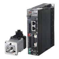
Omron R88M-K Series User Manual (730 pages)
AC SERVOMOTORS/SERVO DRIVES G5-series WITH BUILT-IN EtherCAT COMMUNICATIONS
Brand:
Omron
| Category:
Controller
| Size: 15.63 MB
Table of Contents
Introduction
9
Terms and Conditions Agreement
10
Safety Precautions
12
Items to Check after Unpacking
20
Revision History
21
Structure of this Document
22
Table of Contents
24
Contents
25
Features and System Configuration
31
Outline
32
Features of G5-Series Servo Drives
32
What Is Ethercat
33
Object Dictionary
33
System Configuration
34
Names and Functions
35
Servo Drive Part Names
35
Servo Drive Functions
36
System Block Diagram
37
Applicable Standards
46
EC Directives
46
UL and Cul Standards
46
Korean Radio Regulations (KC)
47
Semi F47
47
Unit Versions
48
Confirmation Method
48
Models and External Dimensions
49
Section 2 Models and External Dimensions
50
Servo System Configuration
50
How to Read Model Numbers
52
Servo Drive
52
Servomotors
53
Reduction Gear (3 Arcminutes Max.)
54
Reduction Gear (15 Arcminutes Max.)
55
Model Tables
56
Servo Drive Model Table
56
Servomotor Model Tables
57
Servo Drive and Servomotor Combination Tables
62
Reduction Gear Model Tables
64
Cable and Peripheral Device Model Tables
68
External and Mounting Dimensions
76
Servo Drive Dimensions
76
Servomotor Dimensions
92
Combinations of Servomotors and Reduction Gears
118
Reduction Gear Dimensions
120
External Regeneration Resistor Dimensions
134
Reactor Dimensions
135
Mounting Bracket (L-Brackets for Rack Mounting) Dimensions
139
Specifications
141
Servo Drive Specifications
142
General Specifications
142
Characteristics
143
Ethercat Communications Specifications
147
Main Circuit and Motor Connections
148
Ethercat Communications Connector Specifications (RJ45)
157
Control I/O Connector Specifications (CN1)
158
Control Input Circuits
161
Control Input Details
161
Control Output Circuits
163
Control Output Details
164
Encoder Connector Specifications (CN2)
168
External Encoder Connector Specifications (CN4)
168
Analog Monitor Connector Specifications (CN5)
171
USB Connector Specifications (CN7)
172
Safety Connector Specifications (CN8)
173
Overload Characteristics (Electronic Thermal Function)
175
Overload Characteristics Graphs
175
Servomotor Specifications
176
General Specifications
176
Characteristics
177
Encoder Specifications
199
Reduction Gear Specifications
200
Models and Specifications
200
Cable and Connector Specifications
207
Bend Radius of Robot Cable
207
Encoder Cable Specifications
209
Absolute Encoder Battery Cable Specifications
214
Motor Power Cable Specifications
215
Connector Specifications
231
Ethercat Communications Cable Specifications
234
Analog Monitor Cable Specifications
237
Control Cable Specifications
239
External Regeneration Resistor Specifications
244
Reactor Specifications
246
Specifications
246
System Design
247
Installation Conditions
248
Servo Drive Installation Conditions
248
Servomotor Installation Conditions
249
Decelerator Installation Conditions
252
Wiring
256
Power Cables for 1,500-R/Min Servomotors
256
Peripheral Equipment Connection Examples
257
Main Circuit and Motor Connections
267
Wiring Conforming to EMC Directives
281
Wiring Method
281
Selecting Connection Component
290
Regenerative Energy Absorption
302
Calculating the Regenerative Energy
302
Servo Drive Regeneration Absorption Capacity
304
Regenerative Energy Absorption with an External Regeneration Resistor
305
Connecting an External Regeneration Resistor
306
Using DC Power Input
309
Connection Example for Using DC Power Input
310
Section 5 Ethercat Communications
314
Display Area and Settings
314
Node Address Setting
314
Status Indicators
315
Structure of the CAN Application Protocol over Ethercat
316
Structure of the CAN Application Protocol
316
Ethercat State Machine
317
Process Data Objects (Pdos)
318
PDO Mapping Settings
318
Sync Manager PDO Assignment Settings
319
Fixed PDO Mapping
319
Variable PDO Mapping
321
Multiple PDO Mapping
322
Service Data Objects (Sdos)
324
Abort Codes
324
Synchronization with Distributed Clocks
325
Communications Cycle (DC Cycle)
325
Emergency Messages
326
Sysmac Device Features
327
Basic Control Functions
331
Section 6 Basic Control Functions
332
Cyclic Synchronous Position Mode
332
Block Diagram for Position Control Mode
334
Cyclic Synchronous Velocity Mode
335
Cyclic Synchronous Torque Mode
338
Profile Position Mode
341
Related Objects
342
Description of Function
343
Controlword (6040 Hex) in Profile Position Mode
344
Statusword (6041 Hex) in Profile Position Mode
344
Homing Mode
345
Fully-Closed Control
346
Outline of Operation
346
Objects Requiring Settings
347
Block Diagram for Fully-Closed Control Mode
352
Connecting with OMRON Controllers
353
7-1 Sequence I/O Signals
362
Forward and Reverse Drive Prohibition Functions
362
Objects Requiring Settings
362
Overrun Protection
365
Operating Conditions
365
Objects Requiring Settings
365
Operation Example
366
Backlash Compensation
367
Objects Requiring Settings
367
Brake Interlock
369
Objects Requiring Settings
369
Operation Timing
373
Electronic Gear Function
375
Objects Requiring Settings
375
Operation Example
376
Torque Limit Switching
378
Operating Conditions
378
Objects Requiring Settings
378
Soft Start
380
Objects Requiring Settings
380
Soft Start Acceleration or Deceleration Time
380
S-Curve Acceleration or Deceleration Time
381
Advertisement
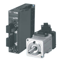
OMRON R88M-K Series User Manual (553 pages)
Accurax G5 servo system with Analogue/Pulse control; Servo Drives/Servomotors
Brand:
OMRON
| Category:
Engine
| Size: 29.35 MB
Table of Contents
Table of Contents
18
Safety Precautions Document
6
Explanation of Symbols
6
Storage and Transportation
9
Maintenance and Inspection
12
Items to Check after Unpacking
14
Manual Revision History
15
Chapter1
16
Structure of this Document
16
Table of Contents
18
Outline
22
Features of the Accurax G5
22
Outline of the Accurax G5
22
System Configuration
23
Names and Functions
24
Driver Part Names
24
Driver Functions
25
System Block Diagrams
26
Applicable Standards
31
EC Directives
31
Functional Safety
31
UL and Cul Standards
31
Standard Models and External Dimensions
33
Chapter 2 Standard Models and External Dimensions
34
Servo System Configuration
34
How to Read Model
36
Servo Drive
36
Servomotor
37
Standard Model List
38
Servo Drive Model List
38
Servomotor Model List
39
Servo Drive and Servomotor Combination List
43
Peripheral Equipment and Cable Model List
45
Servo Relay Unit Cables for Servo Drives
53
Servo Relay Unit Cables for Position Control Units
54
External and Mounting Dimensions
57
Servo Drive Dimensions
57
Servomotor Dimensions
69
External Regeneration Resistor Dimensions
88
EMC Filter Dimensions
89
Specifications
91
Chapter 3 Specifications
92
Driver Specifications
92
General Specifications
92
Characteristics
93
Main Circuit and Motor Connections
99
Control I/O Connector Specifications (CN1)
104
Control Input Circuits
114
Control Input Details
118
Sensor on Input (Sen)
122
Speed Command Sign Input (Vsign)
127
Zero Speed Designation (Vzero)
127
Torque Command Sign Input (Tsign)
128
Torque Limit Switching (Tlsel)
128
Control Output Circuits
130
Control Output Details
131
Speed Conformity Output (Tgon)
134
Torque Limiting Signal (Tlimt)
134
Encoder Connector Specifications (CN2)
136
External Encoder Connector Specifications (CN4)
136
Monitor Connector Specifications (CN5)
140
USB Connector Specifications (CN7)
141
Safety Connector Specifications (CN8)
142
Overload Characteristics (Electronic Thermal Function)
144
Overload Characteristics Graphs
144
Motor Specifications
145
General Specifications
145
Characteristics
146
Encoder Specifications
173
Cable and Connector Specifications
174
Encoder Cable Specifications
174
Motor Power Cable Specifications
176
Connector Specifications
183
Analog Monitor Cable Specifications
186
Control Cable Specifications
188
Servo Relay Units and Cable Specifications
203
Servo Relay Units and Cable Specifications
204
Position Control Unit-Servo Relay Unit Cable Specifications
212
External Regeneration Resistor Specifications
222
EMC Filter Specifications
224
System Design
225
Chapter 4 System Design
226
Installation Conditions
226
Servo Drive Installation Conditions
226
Servomotor Installation Conditions
228
Gearbox Installation Conditions
231
Wiring
232
Peripheral Equipment Connection Examples
232
Main Circuit and Motor Connections
238
Terminal Block Wire Sizes
242
Wiring Conforming to EMC Directives
246
Wiring Method
246
Selecting Connection Component
250
Surge Absorber
252
Surge Suppressor
256
Regenerative Energy Absorption
260
Calculating the Regenerative Energy
260
Driver Regeneration Absorption Capacity
262
Regenerative Energy Absorption with an External Regeneration Resistor
263
Connecting an External Regeneration Resistor
264
Basic Control Mode
267
Chapter 5 BASIC CONTROL Mode
268
Position Control
268
Parameters Requiring Settings
269
Position Control
269
Related Functions
272
Parameter Block Diagram for POSITION CONTROL Mode
273
Speed Control
274
Outline of Operation
274
Parameters Requiring Settings
274
Related Functions
278
Parameter Block Diagram for SPEED CONTROL Mode
279
Torque Control
280
Outline of Operation
280
Parameters Requiring Settings
280
Related Functions
283
Parameter Block Diagram for TORQUE CONTROL Mode
284
Internally Set Speed Control
285
Outline of Operation
285
Parameters Requiring Settings
285
Operation Example
287
Switching Control
288
Outline of Operation
288
Parameters Requiring Settings
288
Related Functions
290
Full Closing Control
291
Parameters Requiring Settings
292
Parameter Block Diagram for FULL CLOSING CONTROL Mode
299
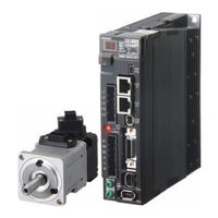
Omron R88M-K Series User Manual (632 pages)
AC SERVOMOTORS/SERVO DRIVES
Brand:
Omron
| Category:
Servo Drives
| Size: 42.98 MB
Table of Contents
Table of Contents
20
Safety Precautions
8
Items to Check after Unpacking
16
Revision History
17
Structure of this Document
18
Table of Contents
20
Chapter 1 Features and System Configuration
24
Outline
24
Features of OMNUC G5-Series Servo Drives
24
Outline of the OMNUC G5 Series
24
System Configuration
25
Names and Functions
26
Servo Drive Part Names
26
Servo Drive Functions
27
System Block Diagrams
28
Applicable Standards
38
EC Directives
38
UL and Cul Standards
38
Korean Radio Regulations (KC)
39
Semi F47
40
Unit Versions
41
Confirmation Method
41
Standard Models and External Dimensions
43
Chapter 2 Standard Models and External Dimensions
44
Servo System Configuration
44
How to Read Model Numbers
46
Servo Drive
46
Servomotor
47
Standard Model Tables
48
Servo Drive Model Table
48
Servomotor Model Tables
49
Servo Drive and Servomotor Combination Tables
54
Peripheral Equipment and Cable Model Tables
56
External and Mounting Dimensions
68
Servo Drive Dimensions
68
Servomotor Dimensions
86
External Regeneration Resistor Dimensions
113
EMC Filter Dimensions
114
Dimensions of Mounting Brackets (L-Brackets for Rack Mounting)
115
Specifications
117
Chapter 3 Specifications
118
Servo Drive Specifications
118
General Specifications
118
Characteristics
119
Main Circuit and Motor Connections
126
Control I/O Connector Specifications (CN1)
135
Control Input Circuits
145
Control Input Details
149
Control Output Circuits
162
Control Output Details
163
Encoder Connector Specifications (CN2)
168
External Encoder Connector Specifications (CN4)
168
Analog Monitor Connector Specifications (CN5)
171
Safety Connector Specifications (CN8)
172
USB Connector Specifications (CN7)
172
Overload Characteristics (Electronic Thermal Function)
175
Overload Characteristics Graphs
175
Servomotor Specifications
176
General Specifications
176
Characteristics
177
Encoder Specifications
213
Cable and Connector Specifications
214
Encoder Cable Specifications
214
Motor Power Cable Specifications
217
Connector Specifications
224
Analog Monitor Cable Specifications
228
Control Cable Specifications
229
Servo Relay Units and Cable Specifications
244
Servo Relay Units and Cable Specifications
246
Position Control Unit-Servo Relay Unit Cable Specifications
253
External Regeneration Resistor Specifications
263
EMC Filter Specifications
265
Advertisement
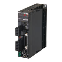
Omron R88M-K Series User Manual (634 pages)
AC SERVOMOTORS/SERVO DRIVES
Brand:
Omron
| Category:
Servo Drives
| Size: 9.31 MB
Table of Contents
Safety Precautions
8
Items to Check after Unpacking
19
Revision History
20
Structure of this Document
21
Chapter1
21
Table of Contents
22
Outline
26
Outline of the OMNUC G5 Series
26
Features of OMNUC G5-Series Servo Drives
26
System Configuration
27
Names and Functions
28
Servo Drive Part Names
28
Servo Drive Functions
29
System Block Diagrams
30
Applicable Standards
40
EC Directives
40
UL and Cul Standards
40
Korean Radio Regulations (KC)
41
Semi F47
42
Unit Versions
43
Confirmation Method
43
Servo System Configuration
46
How to Read Model Numbers
48
Servo Drive
48
Servomotor
49
Standard Model Tables
50
Servo Drive Model Table
50
Servomotor Model Tables
51
Servo Drive and Servomotor Combination Tables
56
Peripheral Equipment and Cable Model Tables
58
External and Mounting Dimensions
70
Servo Drive Dimensions
70
Servomotor Dimensions
88
External Regeneration Resistor Dimensions
115
EMC Filter Dimensions
116
Dimensions of Mounting Brackets (L-Brackets for Rack Mounting)
117
Servo Drive Specifications
120
General Specifications
120
Characteristics
121
Main Circuit and Motor Connections
128
Control I/O Connector Specifications (CN1)
137
Control Input Circuits
147
Control Input Details
151
Control Output Circuits
164
Control Output Details
165
Encoder Connector Specifications (CN2)
170
External Encoder Connector Specifications (CN4)
170
Analog Monitor Connector Specifications (CN5)
173
USB Connector Specifications (CN7)
174
Safety Connector Specifications (CN8)
174
Overload Characteristics (Electronic Thermal Function)
177
Overload Characteristics Graphs
177
Servomotor Specifications
178
General Specifications
178
Characteristics
179
Encoder Specifications
215
Cable and Connector Specifications
216
Encoder Cable Specifications
216
Motor Power Cable Specifications
219
Connector Specifications
226
Analog Monitor Cable Specifications
230
Control Cable Specifications
231
Servo Relay Units and Cable Specifications
246
Servo Relay Units Specifications
246
Position Control Unit-Servo Relay Unit Cable Specifications
255
External Regeneration Resistor Specifications
265
EMC Filter Specifications
267
Installation Conditions
270
Space Conditions Around Servo Drives
270
Servomotor Installation Conditions
272
Decelerator Installation Conditions
275
Wiring
276
Peripheral Equipment Connection Examples
277
Main Circuit and Motor Connections
287
Wiring Conforming to EMC Directives
302
Wiring Method
302
Selecting Connection Component
310
Regenerative Energy Absorption
322
Regenerative Energy Calculation
322
Servo Drive Regeneration Absorption Capacity
325
Regenerative Energy Absorption with an External Regeneration Resistor
326
Omron R88M-K Series User Manual (484 pages)
AC SERVOMOTORS/SERVO DRIVES WITH BUILT-IN EtherCAT COMMUNICATIONS
Brand:
Omron
| Category:
Servo Drives
| Size: 12.37 MB
Table of Contents
Items to Check after Unpacking
13
Revision History
14
Structure of this Document
15
Table of Contents
16
Chapter 1 Features and System Configuration
24
Outline
24
Outline of the OMNUC G5 Series
24
Features of OMNUC G5-Series Servo Drives
24
What Is Ethercat
25
Object Dictionary
25
System Configuration
26
Names and Functions
27
Servo Drive Part Names
27
Servo Drive Functions
28
System Block Diagram
29
Applicable Standards
34
EC Directives
34
UL and Cul Standards
35
Chapter 2 Models and External Dimensions
38
Servo System Configuration
38
How to Read Model Numbers
40
Servo Drive
40
Servomotors
41
Model Tables
42
Servo Drive Model Table
42
Servomotor Model Tables
43
Servo Drive and Servomotor Combination Tables
47
Cable and Peripheral Device Model Tables
49
External and Mounting Dimensions
58
Servo Drive Dimensions
58
Servomotor Dimensions
68
External Regeneration Resistor Dimensions
87
EMC Filter Dimensions
88
Chapter 3 Specifications
90
Servo Drive Specifications
90
General Specifications
90
Characteristics
91
Ethercat Communications Specifications
95
Main Circuit and Motor Connections
96
Ethercat Communications Connector Specifications (RJ45)
101
Control I/O Connector Specifications (CN1)
102
Control Input Circuits
105
Control Input Details
106
Control Output Circuits
108
Control Output Details
109
Encoder Connector Specifications (CN2)
112
External Encoder Connector Specifications (CN4)
112
Analog Monitor Connector Specifications (CN5)
116
USB Connector Specifications (CN7)
117
Safety Connector Specifications (CN8)
118
Overload Characteristics (Electronic Thermal Function)
120
Overload Characteristics Graphs
120
Servomotor Specifications
121
General Specifications
121
Characteristics
122
Encoder Specifications
145
Cable and Connector Specifications
146
Encoder Cable Specifications
146
Absolute Encoder Battery Cable Specifications
148
Motor Power Cable Specifications
149
Connector Specifications
156
Ethercat Communications Cable Specifications
159
Analog Monitor Cable Specifications
162
Control Cable Specifications
164
External Regeneration Resistor Specifications
169
External Regeneration Resistor Specifications
170
EMC Filter Specifications
171
Chapter 4 System Design
174
Installation Conditions
174
Servo Drive Installation Conditions
174
Servomotor Installation Conditions
175
Decelerator Installation Conditions
178
Wiring
179
Peripheral Equipment Connection Examples
179
Main Circuit and Motor Connections
185
Wiring Conforming to EMC Directives
193
Wiring Method
193
Selecting Connection Component
200
Regenerative Energy Absorption
214
Calculating the Regenerative Energy
214
Servo Drive Regeneration Absorption Capacity
216
Regenerative Energy Absorption with an External Regeneration Resistor
217
Connecting an External Regeneration Resistor
218
Chapter 5 Ethercat Communications
222
Display Area and Settings
222
Node Address Setting
222
Status Indicators
223
Structure of the CAN Application Protocol over Ethercat
224
Ethercat State Machine
225
Process Data Objects (Pdos)
226
PDO Mapping Settings
226
Sync Manager PDO Assignment Settings
227
Fixed PDO Mapping
227
Service Data Objects (Sdos)
228
Abort Codes
228
Synchronization with Distributed Clocks
229
Communications Cycle (DC Cycle)
229
Emergency Messages
230
Chapter 6 Drive Profile
232
Controlling the State Machine of the Servo Drive
232
State Machine
232
Modes of Operation
235
Cyclic Synchronous Position Mode
236
Block Diagram for Position Control Mode
238
Torque Limit
239
Related Objects
239
Touch Probe Function (Latch Function)
240
Related Objects
240
Trigger Signal Settings
240
Fully-Closed Control
243
Outline of Operation
243
Objects Requiring Settings
244
Parameter Block Diagram for Fully-Closed Control Mode
249
Object Description Format
251
Communication Objects
252
PDO Mapping Objects
258
Sync Manager Communication Objects
260
Manufacturer Specific Objects
264
Servo Drive Profile Object
267
Reserved Objects
283
Connecting with OMRON Controllers
284
Related Objects
284
OMRON R88M-K Series User Manual (550 pages)
AC SERVOMOTORS/SERVO DRIVES
Brand:
OMRON
| Category:
Computer Hardware
| Size: 39.02 MB
Table of Contents
Table of Contents
16
Safety Precautions Document
6
Items to Check after Unpacking
13
Manual Revision History
14
Structure of this Document
15
Table of Contents
16
Chapter 1 Features and System Configuration
20
Outline
20
Features of the OMNUC G5 Series
20
Outline of the OMNUC G5 Series
20
System Configuration
21
Names and Functions
22
Driver Part Names
22
Driver Functions
23
System Block Diagrams
24
Applicable Standards
25
EC Directives
25
Functional Safety
25
UL and Cul Standards
25
Standard Models and External Dimensions
27
Chapter 2 Standard Models and External Dimensions
28
Servo System Configuration
28
How to Read Model
30
Servo Drive
30
Servomotor
31
Standard Model List
32
Servo Drive Model List
32
Servomotor Model List
33
Servo Drive and Servomotor Combination List
37
Peripheral Equipment and Cable Model List
39
External and Mounting Dimensions
49
Servo Drive Dimensions
49
Servomotor Dimensions
61
External Regeneration Resistor Dimensions
80
EMC Filter Dimensions
81
Specifications
83
Chapter 3 Specifications
84
Driver Specifications
84
General Specifications
84
Characteristics
85
Main Circuit and Motor Connections
91
Control I/O Connector Specifications (CN1)
96
Control Input Circuits
106
Control Input Details
110
Control Output Circuits
122
Control Output Details
123
Encoder Connector Specifications (CN2)
128
External Encoder Connector Specifications (CN4)
128
Monitor Connector Specifications (CN5)
132
USB Connector Specifications (CN7)
133
Safety Connector Specifications (CN8)
134
Overload Characteristics (Electronic Thermal Function)
136
Overload Characteristics Graphs
136
Motor Specifications
137
General Specifications
137
Characteristics
138
Encoder Specifications
160
Cable and Connector Specifications
161
Encoder Cable Specifications
161
Motor Power Cable Specifications
163
Connector Specifications
169
Analog Monitor Cable Specifications
172
Control Cable Specifications
174
Servo Relay Units and Cable Specifications
189
Servo Relay Units Specifications
189
Servo Drive-Servo Relay Unit Cable Specifications
202
Position Control Unit-Servo Relay Unit Cable Specifications
206
External Regeneration Resistor Specifications
219
EMC Filter Specifications
221
System Design
223
Chapter 4 System Design
224
Installation Conditions
224
Servo Drive Installation Conditions
224
Servomotor Installation Conditions
226
Gearbox Installation Conditions
229
Wiring
230
Peripheral Equipment Connection Examples
230
Main Circuit and Motor Connections
236
Wiring Conforming to EMC Directives
244
Wiring Method
244
Selecting Connection Component
248
Regenerative Energy Absorption
260
Calculating the Regenerative Energy
260
Driver Regeneration Absorption Capacity
262
Regenerative Energy Absorption with an External Regeneration Resistor
263
Connecting an External Regeneration Resistor
264
Omron R88M-K Series User Manual (484 pages)
AC SERVOMOTORS/SERVO DRIVES WITH BUILT-IN MECHATROLINK-II COMMUNICATIONS
Brand:
Omron
| Category:
Servo Drives
| Size: 6.59 MB
Table of Contents
Application Considerations
5
Disclaimers
5
Safety Precautions Document
6
Items to Check after Unpacking
15
Manual Revision History
16
Outline
17
Structure of this Document
17
System Configuration
17
Table of Contents
18
Features of the OMNUC G5 Series
26
Outline
26
Outline of the OMNUC G5 Series
26
System Configuration
28
Names and Functions
29
Servo Drive Part Names
29
Servo Drive Functions
30
System Block Diagrams
31
System Block Diagrams
32
Applicable Standards
36
EC Directives
36
UL and Cul Standards
36
Korean Radio Regulations (KC)
37
Semi F47
37
Confirmation Method
38
Unit Versions
38
Unit Versions
39
Servo System Configuration
42
How to Read Model
44
Servo Drive
44
Servomotor
45
Servo Drive Model List
46
Standard Model List
46
Servomotor Model List
47
Servo Drive and Servomotor Combination List
51
Cables and Peripheral Devices Model List
53
External and Mounting Dimensions
59
Servo Drive Dimensions
59
Servomotor Dimensions
70
External Regeneration Resistor Dimensions
90
EMC Filter Dimensions
91
EMC Filter Dimensions
92
MECHATROLINK-II Repeater Units
92
Dimensions of Mounting Brackets (L-Brackets for Rack Mounting)
93
General Specifications
96
Servo Drive Specifications
96
Characteristics
97
Main Circuit and Motor Connections
103
Control I/O Connector Specifications (CN1)
108
Control Input Circuits
111
Control Input Details
112
Control Output Circuits
114
Control Output Details
115
Encoder Connector Specifications (CN2)
119
External Encoder Connector Specifications (CN4)
119
Monitor Connector Specifications (CN5)
123
USB Connector Specifications (CN7)
124
Safety Connector Specifications (CN8)
125
Overload Characteristics (Electronic Thermal Function)
127
Overload Characteristics Graphs
127
General Specifications
128
Servomotor Specifications
128
Characteristics
129
Encoder Specifications
152
Cable and Connector Specifications
153
Encoder Cable Specifications
153
Absolute Encoder Battery Cable Specifications
155
Motor Power Cable Specifications
156
Connector Specifications
162
Analog Monitor Cable Specifications
165
MECHATROLINK-II Communications Cable Specifications
167
Control Cable Specifications
169
External Regeneration Resistor Specifications
174
External Regeneration Resistor Specifications
175
Reactor Filter Specifications
176
Specifications
176
MECHATROLINK-II Repeater Unit Specifications
177
Specifications
177
Connection Method
178
Repeater Unit Part Names
178
Installation Conditions
180
Servo Drive Installation Conditions
180
Servomotor Installation Conditions
182
Decelerator Installation Conditions
185
Peripheral Equipment Connection Examples
186
Wiring
186
Main Circuit and Motor Connections
192
Wiring Conforming to EMC Directives
200
Wiring Method
200
Selecting Connection Component
208
Conformity to IEC 61800-5-1
224
Regenerative Energy Absorption
226
Regenerative Energy Calculation
226
Servo Drive Regeneration Absorption Capacity
229
Regenerative Energy Absorption with an External Regeneration Resistor
230
Connecting an External Regeneration Resistor
231
Adjustment When the Load Inertia Is Large
233
Dynamic Brake When the Load Inertia Is Large
233
Large Load Inertia Adjustment and Dynamic Brake
233
Parameters Requiring Settings
236
Position Control
236
Related Functions
237
Parameter Block Diagram for POSITION CONTROL Mode
238
Parameters Requiring Settings
239
Related Functions
239
Speed Control
239
Parameter Block Diagram for SPEED CONTROL Mode
240
Parameters Requiring Settings
241
Torque Control
241
Related Functions
242
Parameter Block Diagram for TORQUE CONTROL Mode
243
Full Closing Control
244
Outline of Operation
244
Parameters Requiring Settings
245
Parameter Block Diagram for FULL CLOSING CONTROL Mode
251
Input Signals
254
Sequence I/O Signal
254
Output Signals
257
Forward and Reverse Drive Prohibition Functions
259
Parameters Requiring Settings
259
Operating Conditions
263
Overrun Protection
263
Parameters Requiring Settings
263
Operation Example
264
Backlash Compensation
265
Parameters Requiring Settings
265
Brake Interlock
267
Parameters Requiring Settings
267
Operating Example
268
Electronic Gear Function
272
Parameters Requiring Settings
272
Operation Example
274
Operating Conditions
275
Parameters Requiring Settings
275
Torque Limit Switching
275
Parameters Requiring Settings
277
Soft Start
277
Soft Start Acceleration or Deceleration Time
277
S-Curve Acceleration or Deceleration Time
278
Gain Switching Function
279
Parameters Requiring Settings
280
Gain Switching Setting for each CONTROL Mode
281
Timing by Gain Switching Setting
286
Gain Switching 3 Function
290
Operating Conditions
290
Parameters Requiring Settings
290
Operation Example
291
Omron R88M-K Series Manual (42 pages)
AC Servomotor/Servo Drives
Brand:
Omron
| Category:
DC Drives
| Size: 1.49 MB
Table of Contents
Introduction
3
Intended Audience
3
Applicable Products
3
Terms and Conditions Agreement
4
Precautions
6
Trademarks
6
Revision History
7
Table of Contents
8
Outline
9
Precautions for Replacement
10
Replacement List
11
Servomotors with Rated Rotation Speed of 3,000 R/Min
11
Flat Servomotors with Rated Rotation Speed of 3,000 R/Min
11
Comparison of Servomotor Dimensions
12
Servomotors with Rated Rotation Speed of 3,000 R/Min (Main Circuit Power Supply Voltage: 100 V or 200 V)
12
Comparison of Servo Drive Dimensions
15
Layout and Specifications of Connectors and Terminal Blocks of Servo Drive
16
Layout and Specifications of Connectors and Terminal Blocks of Main Circuit Wiring and Motor Wiring
16
Layout and Specifications of Connectors of Control Circuit
17
Gain Adjustment Methods
22
Gain Adjustment Method (Auto Tuning)
22
Using Gain Adjustment Values for SS2 Series as those for G5 Series
27
Connecting with Host Controllers
28
Detailed Comparison of Parameters
29
Function Selection Parameters
29
Parameters Related to Gain
31
Parameters Related to Position Control
35
Parameters Related to Internally Set Speed Control
37
Parameters Related to Sequence
38
Appendix. List of Cables Connecting G5-Series Servo Drives and Servomotors
41
Omron R88M-K Series Startup Manual (47 pages)
Programmable Multi-Axis Controller, Servo Drivers, IDEv4
Brand:
Omron
| Category:
Servo Drives
| Size: 1.79 MB
Table of Contents
Table of Contents
3
1 Related Manuals
4
2 Terms and Definitions
5
3 Precautions
6
4 Overview
7
5 Applicable Devices and Device Configuration
8
Applicable Devices
8
Device Configuration
9
6 Ethercat Connection Procedure
10
Workflow
10
Preparation for the Controller Setup
12
Installation of ESI Files
17
Ethercat Communications Setup
17
Controller Settings
25
7 Appendix Saving and Loading a Project
36
Saving a Project
36
Loading and Downloading a Project
38
8 Appendix Troubleshooting
41
Factors Causing Ethercat Communications to be Unavailable, and Corrective Actions
41
How to Check for Errors
42
9 Appendix Ecat[I] Structure Elements
45
10 Revision History
46
OMRON R88M-K Series System Configuration Manual (14 pages)
servo motors
Brand:
OMRON
| Category:
Engine
| Size: 1.17 MB
Table of Contents
Servo Motor Specifications
3
Ratings and Specifications
3
Torque-Speed Characteristics
3
Ordering Information
9
Advertisement
Related Products
Omron R88M-1AL1K030T-S2
Omron R88M-1AL2K030T-OS2
Omron R88M-1AL1K530C-BOS2
Omron R88M-1AM2K715T-O
Omron R88M-1AM1K515C-O
Omron R88M-1M5K515C-O
Omron R88M-1M7K515C-OS2
Omron R88M-1M4K015C-BS2
Omron R88M-1M5K515C-BO
Omron R88M-1M90010T
Omron Categories
Blood Pressure Monitor
Controller
Accessories
Switch
Inverter
More Omron Manuals
Login
Sign In
OR
Sign in with Facebook
Sign in with Google
Upload manual
Upload from disk
Upload from URL