
Subscribe to Our Youtube Channel
Related Manuals for Omron OMNUC G


Summary of Contents for Omron OMNUC G
- Page 1 Cat. No. I566-E1-01 USER’S MANUAL OMNUC G SERIES R88M-G@ (AC Servomotors) R88D-GN@-ML2 (AC Servo Drives) AC SERVOMOTORS/SERVO DRIVES WITH BUILT-IN MECHATROLINK-II COMMUNICATIONS...
- Page 2 MECHATROLINK is a registered trademark of the MECHATROLINK Members Association. © OMRON, 2008 All rights reserved. No part of this publication may be reproduced, stored in a retrieval system, or transmitted, in any form, or by any means, mechanical, electronic, photocopying, recording, or otherwise, without the prior written permis- sion of OMRON.
- Page 3 Personnel in charge of managing FA systems and facilities NOTICE This manual contains information necessary to ensure safe and proper use of the OMNUC G Series and its peripheral devices. Please read this manual thoroughly and understand its contents before using the products.
- Page 4 PRODUCTS, WHETHER SUCH CLAIM IS BASED ON CONTRACT, WARRANTY, NEGLIGENCE, OR STRICT LIABILITY. In no event shall the responsibility of OMRON for any act exceed the individual price of the product on which liability is asserted. IN NO EVENT SHALL OMRON BE RESPONSIBLE FOR WARRANTY, REPAIR, OR OTHER CLAIMS...
- Page 5 The following are some examples of applications for which particular attention must be given. This is not intended to be an exhaustive list of all possible uses of the products, nor is it intended to imply that the uses listed may be suitable for the products: •...
- Page 6 PERFORMANCE DATA Performance data given in this manual is provided as a guide for the user in determining suitability and does not constitute a warranty. It may represent the result of OMRON's test conditions, and the users must correlate it to actual application requirements.
- Page 7 This manual may include illustrations of the product with protective covers or shields removed in order to show the components of the product in detail. Make sure that these protective covers and shields are put in place as specified before using the product.
- Page 8 Doing so may result in electric shock. Do not damage or pull on the cables, place heavy objects on them, or subject them to excessive stress. Doing so may result in electric shock, stopping product operation, or burning.
- Page 9 Use the Servomotors and Servo Drives in a specified combination. Using them incorrectly may result in fire or damage to the products. Do not store or install the product in the following places. Doing so may result in fire, electric shock, or damage to the product.
- Page 10 Do not step on or place a heavy object on the product. Doing so may result in injury. Do not cover the inlet or outlet ports and prevent any foreign objects from entering the product. Covering them or not preventing entry of foreign objects may result in fire.
- Page 11 Operation and Adjustment Precautions Caution Confirm that no adverse effects will occur in the system before performing the test operation. Not doing so may result in equipment damage. Check the newly set parameters for proper operation before actually running them.
- Page 12 (R88D-GN01H-ML2) Warning Label Contents Disposing of the Product • Dispose of the batteries according to local ordinances and regulations. Wrap the batteries in tape or other insulative material before disposing of them. • Dispose of the product as industrial waste.
-
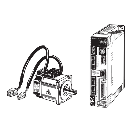
Page 13: Items To Check When Unpacking
Accessories Provided with Product Safety Precautions document × 1 • No connectors or mounting screws are provided. They have to be prepared by the user. • Should you find any problems (missing parts, damage to the Servo Drive, etc.), please contact your local sales representative or OMRON sales office. - Page 14 Rated Rotation Speed 1,000 r/min 1,500 r/min 2,000 r/min 3,000 r/min Applied Voltage 200 VAC with incremental encoder specifications 100 VAC with incremental encoder specifications 200 VAC with absolute encoder specifications 100 VAC with absolute encoder specifications Option Blank: Straight shaft...
- Page 15 Items to Check When Unpacking Understanding Decelerator Model Numbers (Backlash = 3' Max.) R88G-HPG14A05100PBJ Decelerator for G-Series Servomotors Backlash = 3’ Max. Flange Size Number :@40 :@60 :@90 :@120 :@170 :@230 Gear Ratio :1/5 :1/9 (only frame number 11A) :1/11 (except frame number 65A)
- Page 16 Items to Check When Unpacking Understanding Decelerator Model Numbers (Backlash = 15' Max.) R88G-VRSF09B100PCJ Decelerator for G-Series Servomotors Backlash = 15’ Max. Gear Ratio :1/5 :1/9 :1/15 :1/25 Flange Size Number :@52 :@78 :@98 Applicable Servomotor Capacity : 50 W...
-
Page 17: About This Manual
About This Manual About This Manual This manual consists of the following chapters. Refer to this table and chose the required chapters of the manual. Overview Features and System Describes the features and names of parts of the product as well... -
Page 18: Table Of Contents
Table of Contents Introduction ..................1 Read and Understand This Manual ..........2 Precautions for Safe Use..............5 Items to Check When Unpacking ............ 11 About This Manual................15 Chapter 1 Features and System Configuration Overview................... 1-1 System Configuration ............... 1-2 Names of Parts and Functions ............ - Page 19 Table of Contents Chapter 5 Operating Functions Position Control................5-1 Speed Control .................. 5-4 Torque Control ................. 5-7 Forward and Reverse Drive Prohibit ..........5-10 Brake Interlock ................. 5-11 Torque Limit ..................5-16 Soft Start ..................5-18 Acceleration/Deceleration Time Settings ......... 5-19 Moving Average Time ..............
- Page 20 Table of Contents Chapter 8 Troubleshooting Error Processing................8-1 Alarm Table ..................8-3 Troubleshooting................8-7 Overload Characteristics (Electronic Thermal Function) ....8-20 Periodic Maintenance ............... 8-21 Chapter 9 Appendix Parameter Tables ................9-1...
- Page 21 Features and System Configuration 1-1 Overview ............1-1 Overview ................1-1 Features................1-1 1-2 System Configuration......... 1-2 1-3 Names of Parts and Functions ......1-3 Servo Drive Part Names ............1-3 Servo Drive Functions............1-4 1-4 System Block Diagrams ........1-5 1-5 Applicable Standards ......... 1-10 EC Directives ................1-10...
-
Page 22: Overview
This makes it possible to use the Servo Drive’s various control parameters and monitor data via a host controller, allowing you to unify the system data control. -
Page 23: System Configuration
1-2 System Configuration 1-2 System Configuration Controller (MECHATROLINK-ll type) MECHATRO LINK-II Programmable Controller Position Control Unit SYSMAC CJ1 CJ1W-NCF71 OMNUC G-Series AC Servo Drive R88D-GN@-ML2 MECHATRO LINK-II Controller (MECHATROLINK-ll type) OMNUC G-Series Programmable Controller Position Control Unit AC Servomotor SYSMAC CS1... -
Page 24: Names Of Parts And Functions
1-3 Names of Parts and Functions 1-3 Names of Parts and Functions Servo Drive Part Names Display area Rotary switches AC SERVO DRIVE MECHATROLINK-II communications status LED indicator RS-232 communications connector Analog monitor check pins MECHATROLINK-II communications connector CN6A CN6B... -
Page 25: Servo Drive Functions
The actual motor speed, command speed, torque, and number of accumulated pulses can be measured based on the analog voltage level by using an oscilloscope. Set the type of signal to be output and the output voltage level by setting the Speed Monitor (SP) Selection (Pn007) and Torque Monitor (IM) Selection (Pn008). -
Page 26: System Block Diagrams
Main circuit drive control detection control VCC1 Internal control Display/ MPU & ASIC power ±VCC setting circuits supply Position, speed, and torque processor, PWM control ±S Encoder communications interface + E5V MECHATROLINK-II Control I/O interface interface RS-232 + BAT interface CN6A... - Page 27 Main circuit drive detection control control VCC1 Internal control Display/ MPU & ASIC power ±VCC setting circuits Position, speed, and torque processor, supply PWM control ±S Encoder communications interface + E5V MECHATROLINK-II Cooling fan Control I/O interface interface RS-232 + BAT...
- Page 28 Internal VCC1 control Display/ MPU & ASIC power ±VCC setting circuits supply Position, speed, and torque processor, PWM control ±S Encoder communications interface + E5V MECHATROLINK-II Control I/O interface interface RS-232 + BAT interface Cooling fan...
- Page 29 Internal VCC1 control Display/ MPU & ASIC power ±VCC setting circuits supply Position, speed, and torque processor, PWM control ±S Encoder communications interface + E5V MECHATROLINK-II Control I/O interface Cooling fan interface RS-232 + BAT interface...
- Page 30 Main circuit drive detection control control VCC1 Internal Display/ control MPU & ASIC setting circuits ±VCC power Position, speed, and torque processor, supply PWM control ±S Encoder communications interface + E5V MECHATROLINK-II Cooling fan Control I/O interface interface RS-232 + BAT...
-
Page 31: Applicable Standards
High-frequency conduction immunity testing IEC 61000-4-11 Momentary power interruption immunity testing Note To conform to the EMC Directives, the Servomotor and Servo Drive must be installed under the conditions described in Wiring Conforming to EMC Directives on page 4-26. UL and CSA Standards... - Page 33 2-1 Standard Models ..........2-1 Servo Drives .................2-1 Servomotors................2-2 Servo Drive-Servomotor Combinations ........2-5 Decelerators................2-7 Accessories and Cables ............2-14 2-2 External and Mounting Hole Dimensions ... 2-23 Servo Drives .................2-23 Servomotors................2-33 Parameter Unit Dimensions ..........2-43 Servomotor and Decelerator Combinations......2-44 Decelerator Dimensions............2-47 External Regeneration Resistor Dimensions ......2-61...
-
Page 34: Standard Models
2-1 Standard Models 2-1 Standard Models Servo Drives Specifications Model 50 W R88D-GNA5L-ML2 100 W R88D-GN01L-ML2 Single-phase 100 VAC 200 W R88D-GN02L-ML2 400 W R88D-GN04L-ML2 50 W R88D-GN01H-ML2 100 W Single-phase 200 VAC 200 W R88D-GN02H-ML2 400 W R88D-GN04H-ML2 750 W... - Page 35 750 W R88M-G75030H-B R88M-G75030H-BS2 R88M-G75030T-B R88M-G75030T-BS2 200 V 1 kW R88M-G1K030T-B R88M-G1K030T-BS2 1.5kW R88M-G1K530T-B R88M-G1K530T-BS2 2 kW R88M-G2K030T-B R88M-G2K030T-BS2 3 kW R88M-G3K030T-B R88M-G3K030T-BS2 4 kW R88M-G4K030T-B R88M-G4K030T-BS2 5 kW R88M-G5K030T-B R88M-G5K030T-BS2 Note Models with oil seals are also available.
- Page 36 200 V 3 kW R88M-G3K020T-B R88M-G3K020T-BS2 brake 4 kW R88M-G4K020T-B R88M-G4K020T-BS2 5 kW R88M-G5K020T-B R88M-G5K020T-BS2 7.5 kW R88M-G7K515T-B R88M-G7K515T-BS2 Note 1. Models with oil seals are also available. Note 2. The rated rotation speed for 7.5-kW Servomotors is 1,500 r/min.
- Page 37 4.5 kW R88M-G4K510T R88M-G4K510T-S2 6 kW R88M-G6K010T R88M-G6K010T-S2 900 W R88M-G90010T-B R88M-G90010T-BS2 2 kW R88M-G2K010T-B R88M-G2K010T-BS2 With 200 V 3 kW R88M-G3K010T-B R88M-G3K010T-BS2 brake 4.5 kW R88M-G4K510T-B R88M-G4K510T-BS2 6 kW R88M-G6K010T-B R88M-G6K010T-BS2 Note Models with oil seals are also available.
-
Page 38: Standard Models
The tables in this section show the possible combinations of OMNUC G-Series Servo Drives and Servomotors. The Servomotors and Servo Drives can only be used in the listed combinations. The box (-@) at the end of the model number is for options, such as the shaft type, brake and Decelerators. - Page 39 2-1 Standard Models 2,000-r/min Servomotors and Servo Drives Servomotor Voltage Servo Drive Rated With absolute encoder output Single- 1 kW R88M-G1K020T- R88D-GN10H-ML2 phase/three- 1.5 kW R88M-G1K520T- R88D-GN15H-ML2 phase 200 V 2 kW R88M-G2K020T- R88D-GN20H-ML2 3 kW R88M-G3K020T- R88D-GN30H-ML2 Three-phase 4 kW...
-
Page 40: Decelerators
2-1 Standard Models Decelerators The following types of Decelerators are available for OMNUC G-Series Servomotors. Select a Decelerator based on the Servomotor capacity. Backlash = 3’ Max. Decelerators for 3,000-r/min Servomotors Specifications Model Motor Gear ratio capacity R88G-HPG11A05100B R88G-HPG11A09050B 50 W... - Page 41 5 kW 1/11 R88G-HPG50A115K0B Note 1. The standard models have a straight shaft. Note 2. Models with a key and tap are indicated with "J" at the end of the model number (the suffix shown in the box). (Example: R88G-HPG11A05100BJ)
- Page 42 7.5 kW 1/12 R88G-HPG65A127K5SB Note 1. The standard models have a straight shaft. Note 2. Models with a key and tap are indicated with "J" at the end of the model number (the suffix shown in the box). (Example: R88G-HPG32A053K0BJ)
- Page 43 6 kW 1/12 R88G-HPG65A127K5SB Note 1. The standard models have a straight shaft. Note 2. Models with a key and tap are indicated with "J" at the end of the model number (the suffix shown in the box). (Example: R88G-HPG32A05900TBJ) 2-10...
- Page 44 R88G-HPG32A33400PB 1/45 R88G-HPG32A45400PB Note 1. The standard models have a straight shaft. Note 2. Models with a key and tap are indicated with "J" at the end of the model number (the suffix shown in the box). (Example: R88G-HPG11A05100PBJ) 2-11...
- Page 45 2-1 Standard Models Backlash = 15’ Max. Decelerators for 3,000-r/min Servomotors (Straight Shaft with Key) Specifications Model Motor Gear ratio capacity R88G-VRSF05B100CJ R88G-VRSF09B100CJ 50 W 1/15 R88G-VRSF15B100CJ 1/25 R88G-VRSF25B100CJ R88G-VRSF05B100CJ R88G-VRSF09B100CJ 100 W 1/15 R88G-VRSF15B100CJ 1/25 R88G-VRSF25B100CJ R88G-VRSF05B200CJ R88G-VRSF09C200CJ 200 W...
- Page 46 2-1 Standard Models Decelerators for 3,000-r/min Flat Servomotors (Straight Shaft with Key) Specifications Model Motor Gear ratio capacity R88G-VRSF05B100PCJ R88G-VRSF09B100PCJ 100 W 1/15 R88G-VRSF15B100PCJ 1/25 R88G-VRSF25B100PCJ R88G-VRSF05B200PCJ R88G-VRSF09C200PCJ 200 W 1/15 R88G-VRSF15C200PCJ 1/25 R88G-VRSF25C200PCJ R88G-VRSF05C400PCJ R88G-VRSF09C400PCJ 400 W 1/15 R88G-VRSF15C400PCJ...
-
Page 47: Accessories And Cables
R88A-CRGA003C R88A-CRGA005C 10 m R88A-CRGA010C 3,000-r/min Servomotors of 50 to 750 W 15 m R88A-CRGA015C with an absolute encoder, 3,000-r/min Flat Servomotors of 100 to 400 W 20 m R88A-CRGA020C with an absolute encoder 30 m R88A-CRGA030C 40 m R88A-CRGA040C... - Page 48 Specifications For Servomotor without For Servomotor with brake brake R88A-CAGA003S R88A-CAGA005S 10 m R88A-CAGA010S 3,000-r/min Servomotors of 50 to 750 W, 15 m R88A-CAGA015S 3,000-r/min Flat Servomotors of 20 m R88A-CAGA020S 100 to 400 W 30 m R88A-CAGA030S 40 m...
- Page 49 Note There are separate connectors for power and brakes for 3,000-r/min Servomotors of 50 to 750 W, Flat Servomotors, and Servomotors of 6 kW or higher. Therefore, when a Servomotor with a brake is used, it will require both a Power Cable for a Servomotor without a brake and a Brake Cable.
- Page 50 Brake Cables (Standard Cables) Specifications Model R88A-CAGA003B R88A-CAGA005B 10 m R88A-CAGA010B 15 m R88A-CAGA015B 3,000-r/min Servomotors of 50 to 750 W, 3,000-r/min Flat Servomotors of 100 to 400 W 20 m R88A-CAGA020B 30 m R88A-CAGA030B 40 m R88A-CAGA040B 50 m R88A-CAGA050B R88A-CAGE003B...
- Page 51 R88A-CRGA003CR R88A-CRGA005CR 10 m R88A-CRGA010CR 3,000-r/min Servomotors of 50 to 750 W 15 m R88A-CRGA015CR with an absolute encoder, 3,000-r/min Flat Servomotors of 100 to 400 W 20 m R88A-CRGA020CR with an absolute encoder 30 m R88A-CRGA030CR 40 m R88A-CRGA040CR...
- Page 52 Note There are separate connectors for power and brakes for 3,000-r/min Servomotors of 50 to 750 W and Flat Servomotors. Therefore, when a Servomotor with a brake is used, it will require a Power Cable for a Servomotor without a brake, as well as a Brake Cable.
- Page 53 Brake Cables (Robot Cables) Specifications Model R88A-CAGA003BR R88A-CAGA005BR 10 m R88A-CAGA010BR 15 m R88A-CAGA015BR 3,000-r/min Servomotors of 50 to 750 W, 3,000-r/min Flat Servomotors of 100 to 400 W 20 m R88A-CAGA020BR 30 m R88A-CAGA030BR 40 m R88A-CAGA040BR 50 m R88A-CAGA050BR Communications Cable...
- Page 54 XW2B-20G5 M3 screw type XW2D-20G6 External Regeneration Resistors Specifications Model ° Regeneration capacity: 20 W, 50 Ω (with 150 C thermal switch) R88A-RR08050S ° Regeneration capacity: 20 W, 100 Ω (with 150 C thermal switch) R88A-RR080100S Regeneration capacity: 70 W, 47 Ω (with 170 °...
- Page 55 2-1 Standard Models Mounting Brackets (L Brackets for Rack Mounting) Specifications Model R88D-GNA5L-ML2/-GN01L-ML2/-GN01H-ML2/-GN02H-ML2 R88A-TK01G R88D-GN02L-ML2/-GN04H-ML2 R88A-TK02G R88D-GN04L-ML2/-GN08H-ML2 R88A-TK03G R88D-GN10H-ML2/-GN15H-ML2 R88A-TK04G Absolute Encoder Backup Battery Specifications Model 2,000 mA·h 3.6 V R88A-BAT01G 2-22...
-
Page 56: External And Mounting Hole Dimensions
2-2 External and Mounting Hole Dimensions 2-2 External and Mounting Hole Dimensions Servo Drives Single-phase 100 VAC: R88D-GNA5L-ML2/-GN01L-ML2 (50 to 100 W) Single-phase 200 VAC: R88D-GN01H-ML2/-GN02H-ML2 (50 to 200 W) Wall Mounting External Dimensions Mounting Hole Dimensions Two, M4 AC SERVO DRIVER ±0.5... - Page 57 2-2 External and Mounting Hole Dimensions Front Panel Mounting (Using Mounting Brackets) External Dimensions Mounting Hole Dimensions Two, M4 5.2 dia. AC SERVO DRIVER Square hole R2.6 ( 42) 2-24...
- Page 58 2-2 External and Mounting Hole Dimensions Single-phase 100 VAC: R88D-GN02L-ML2 (200 W) Single-phase 200 VAC: R88D-GN04H-ML2 (400 W) Wall Mounting External Dimensions Mounting Hole Dimensions Two, M4 AC SERVO DRIVER ±0.5 Front Panel Mounting (Using Mounting Brackets) External Dimensions Mounting Hole Dimensions Two, M4 5.2 dia.
- Page 59 2-2 External and Mounting Hole Dimensions Single-phase 100 VAC: R88D-GN04L-ML2 (400 W) Single-phase 200/Three phase VAC: R88D-GN08H-ML2 (750 W) Wall Mounting External Dimensions Mounting Hole Dimensions Two, M4 AC SERVO DRIVER ±0.5 (67) Front Panel Mounting (Using Mounting Brackets) External Dimensions...
- Page 60 2-2 External and Mounting Hole Dimensions Single-phase/Three-phase 200 VAC: R88D-GN10H-ML2/-GN15H-ML2 (900 W to 1.5 kW) Wall Mounting External Dimensions Mounting Hole Dimensions Two, M4 AC SERVO DRIVER ±0.5 (87) Front Panel Mounting (Using Mounting Brackets) External Dimensions Mounting Hole Dimensions Four, M4 5.2 dia.
- Page 61 2-2 External and Mounting Hole Dimensions Three-phase 200 VAC: R88D-GN20H-ML2 (2 kW) Wall Mounting External Dimensions 17.5 42.5 R2.6 R2.6 dia. AC SERVO DRIVER R2.6 R2.6 dia. 42.5 17.5 Mounting Hole Dimensions Four, M4 ±0.5 18.5 (87) 2-28...
- Page 62 2-2 External and Mounting Hole Dimensions Front Panel Mounting (Using Mounting Brackets) External Dimensions 17.5 42.5 32.1 R2.6 R2.6 dia. AC SERVO DRIVER R2.6 R2.6 dia. 42.5 17.5 Mounting Hole Dimensions Four, M4 Square hole ±0.5 20.5 2-29...
- Page 63 2-2 External and Mounting Hole Dimensions Three-phase 200 VAC: R88D-GN30H-ML2/-GN50H-ML2 (2 to 5 kW) Wall Mounting External Dimensions R2.6 5.2 dia. R2.6 AC SERVO DRIVER R2.6 5.2 dia. R2.6 Mounting Hole Dimensions ±0.5 Six, M4 ±0.5 2-30...
- Page 64 2-2 External and Mounting Hole Dimensions Front Panel Mounting (Using Mounting Brackets) External Dimensions 32.3 R2.6 5.2 dia. R2.6 AC SERVO DRIVER 5.2 dia. R2.6 R2.6 Mounting Hole Dimensions ±0.5 Six, M4 Square hole ±0.5 2-31...
- Page 65 2-2 External and Mounting Hole Dimensions Three-phase 200 VAC: R88D-GN75H-ML2 (7.5 kW) Front Panel Mounting (Using Mounting Brackets) External Dimensions 37.5 339.3 82.5 45.1 (2.3) AC SERVO DRIVER L1 L1 L2 L2 L3 L3 Four, 5.2 dia. Mounting Hole Dimensions...
-
Page 66: Servomotors
Two, 4.3 dia. Dimensions (mm) Model R88M-G05030 26.5 R88M-G10030 46.5 R88M-G05030 26.5 R88M-G10030 46.5 Note The standard models have a straight shaft. Models with a key and tap are indicated with "S2" at the end of the model number. 2-33... - Page 67 M4 2.5 60 6.5 43 4.5 R88M-G40030 135.5 22.5 5h9 R88M-G75030 149.2 35 19 90 Note The standard models have a straight shaft. Models with a key and tap are indicated with "S2" at the end of the model number. 2-34...
- Page 68 98 6.6 R88M-G1K530 115 95 100 135 10 103 R88M-G2K030 Note The standard models have a straight shaft. Models with a key and tap are indicated with "S2" at the end of the model number. 3,000-r/min Servomotors 3 kW R88M-G3K030T(-S2)/-G3K030T-B(S2)
- Page 69 Eight, h: 9 145 dia. M8 (depth: 20) Dimensions (mm) Model R88M-G4K030 R88M-G5K030 R88M-G4K030 R88M-G5K030 Note The standard models have a straight shaft. Models with a key and tap are indicated with "S2" at the end of the model number. 2-36...
- Page 70 R88M-GP20030L-B R88M-GP20030H-B 18 4h9 R88M-GP20030S-B R88M-GP20030T-B 53 5.5 R88M-GP40030L-B R88M-GP40030H-B 22.5 5h9 R88M-GP40030S-B R88M-GP40030T-B Note The standard models have a straight shaft. Models with a key and tap are indicated with "S2" at the end of the model number. 2-37...
- Page 71 Dimensions (mm) Model R88M-G1K020 R88M-G1K520 R88M-G1K020 R88M-G1K520 Note The standard models have a straight shaft. Models with a key and tap are indicated with “S2” at the end of the model number. 2,000-r/min Servomotors 2 kW/3 kW R88M-G2K020T(-S2)/-G3K020T(-S2)/-G2K020T-B(S2)/-G3K020T-B(S2) Servomotor/brake (Dimensions of shaft end...
- Page 72 250 70 35 200 114.3 176 233 143 13.5 50 10h9 8 5 M12 25 Note The standard models have a straight shaft. Models with a key and tap are indicated with "S2" at the end of the model number. 2-39...
- Page 73 Four, 13.5 dia. 24 3.2 connector M16 (depth:32) Dimensions (mm) Model R88M-G7K515 340.5 R88M-G7K515 380.5 Note The standard models have a straight shaft. Models with a key and tap are indicated with "S2" at the end of the model number. 2-40...
- Page 74 35 200 114.3 176 233 3.2 18 143 13.5 50 10h9 8 5 M12 25 Note The standard models have a straight shaft. Models with a key and tap are indicated with "S2" at the end of the model number.
- Page 75 Dimensions (mm) Model R88M-G4K510 300.5 R88M-G4K510 337.5 Note The standard models have a straight shaft. Models with a key and tap are indicated with "S2" at the end of the model number. 1,000-r/min Servomotors 6 kW R88M-G6K010T(-S2)/-G6K010T-B(S2) Brake connector Motor...
-
Page 76: Parameter Unit Dimensions
2-2 External and Mounting Hole Dimensions Parameter Unit Dimensions R88A-PR02G Hand-held Parameter Unit (62) (24) M3 (depth: 5) (15) Mini DIN 8-pin (1500) MD connector 2-43... -
Page 77: Servomotor And Decelerator Combinations
2-2 External and Mounting Hole Dimensions Servomotor and Decelerator Combinations 000-r/min Servomotors 1/11 Motor model (1/9 for flange size 1/21 1/33 1/45 No.11) R88G- R88G- R88G- R88M- HPG11A05100B HPG14A21100B R88G- R88G- HPG11A09050B G05030 (Also used with (Also used with HPG14A33050B... - Page 78 2-2 External and Mounting Hole Dimensions 3,000-r/min Flat Servomotors Motor model 1/11 1/21 1/33 1/45 R88M- R88G- R88G- R88G- R88G- R88G- GP10030 HPG11A05100PB HPG14A11100PB HPG14A21100PB HPG20A33100PB HPG20A45100PB R88M- R88G- R88G- R88G- R88G- R88G- GP20030 HPG14A05200PB HPG20A11200PB HPG20A21200PB HPG20A33200PB HPG20A45200PB R88M-...
- Page 79 2-2 External and Mounting Hole Dimensions 1,000-r/min Servomotors 1/11 1/21 1/33 Motor model (1/12 for flange size (1/20 for flange size (1/25 for flange size No.65) No.65) No.65) R88M- R88G- R88G- R88G- R88G- G90010T HPG32A05900TB HPG32A11900TB HPG50A21900TB HPG50A33900TB R88G- R88M-...
-
Page 80: Decelerator Dimensions
9.0 M4 10 M4 Note 1. The standard models have a straight shaft. Note 2. Models with a key and tap are indicated with "J" at the end of the model number (the suffix shown in the box). (Example: R88G-HPG11A05100BJ) 2-47... - Page 81 71.0 80 89 dia. 105 70 85.0 84.0 7.5 27 1/33 R88G-HPG32A33400B 104.0 133 120 122 dia. 135 70 115.0 114.0 84 98 12.5 35 1/45 R88G-HPG32A45400B 104.0 133 120 122 dia. 135 70 115.0 114.0 84 98 12.5 35 ×...
- Page 82 130 190 145 165 163 122 103 12.0 53 Note 1. The standard models have a straight shaft. Note 2. Models with a key and tap are indicated with "J" at the end of the model number (the suffix shown in the box). (Example: R88G-HPG32A051K0BJ)
- Page 83 2-2 External and Mounting Hole Dimensions Dimensions (mm) Model Key dimensions dimensions 1/5 R88G-HPG32A051K0B M6×12 5.0 M10 1/11 R88G-HPG32A111K0B M6×12 5.0 M10 1 kW 1/21 R88G-HPG32A211K0B M6×12 5.0 M10 1/33 R88G-HPG32A331K0B M6×12 5.0 M10 1/45 R88G-HPG50A451K0B M6×10 5.5 M10 1/5 R88G-HPG32A052K0B M8×10...
- Page 84 14 9.0 M16 Note 1. The standard models have a straight shaft. Note 2. Models with a key and tap are indicated with "J" at the end of the model number (the suffix shown in the box). (Example: R88G-HPG32A053K0BJ) 2-51...
- Page 85 2-2 External and Mounting Hole Dimensions Dimensions (mm) Model 1/5 R88G-HPG50A054K0SB 149 156 170 180×180 190 165 165 163 122 103 12.0 53 1/11 R88G-HPG50A114K0SB 149 156 170 180×180 190 165 165 163 122 103 12.0 53 4 kW 1/20 R88G-HPG65A204K0SB 231 222 230 180×180 260 165 220 214 168 165 12.0 57...
- Page 86 254.5 222 230 180×180 260 200 220 214 168 165 12.0 57 Note 1. The standard models have a straight shaft. Note 2. Models with a key and tap are indicated with "J" at the end of the model number (the suffix shown in the box). (Example: R88G-HPG32A05900TBJ)
- Page 87 2-2 External and Mounting Hole Dimensions Dimensions (mm) Model Key dimensions dimensions 1/5 R88G-HPG32A05900TB M8×25 5.0 M10 1/11 R88G-HPG32A11900TB M8×25 5.0 M10 900 W 1/21 R88G-HPG50A21900TB M8×25 5.5 M10 1/33 R88G-HPG50A33900TB M8×25 5.5 M10 1/5 R88G-HPG32A052K0TB 11 M12×25 5.0 M10 1/11 R88G-HPG50A112K0TB 14 M12×25...
- Page 88 9.0 M5×12 M4 Note 1. The standard models have a straight shaft. Note 2. Models with a key and tap are indicated with "J" at the end of the model number (the suffix shown in the box). (Example: R88G-HPG11A05100PBJ) 2-55...
- Page 89 80×80 105 90 85.0 84.0 59 53 7.5 27 1/33 R88G-HPG32A33400PB 104.0 133 120 122 dia. 135 90 115.0 114.0 84 98 12.5 35 1/45 R88G-HPG32A45400PB 104.0 133 120 122 dia. 135 90 115.0 114.0 84 98 12.5 35 Dimensions (mm)
- Page 90 R88G-VRSF09D750CJ 97.5 61 750 W 1/15 R88G-VRSF15D750CJ 110.0 61 1/25 R88G-VRSF25D750CJ 110.0 61 Note The standard models have a straight shaft with a key. Outline Drawings Four, Z2 (effective depth: L) Four, Z1 C1 × C1 C2 × C2 2-57...
- Page 91 2-2 External and Mounting Hole Dimensions Dimensions (mm) Model Key dimensions R88G-VRSF05B100CJ 20 M4 M5 M3 12 R88G-VRSF09B100CJ 20 M4 M5 M3 12 50 W 1/15 R88G-VRSF15B100CJ 20 M4 M5 M3 12 1/25 R88G-VRSF25B050CJ 20 M4 M5 M3 12 R88G-VRSF05B100CJ...
- Page 92 R88G-VRSF09C400PCJ 89.5 50 400 W 1/15 R88G-VRSF15C400PCJ 100.0 50 1/25 R88G-VRSF25C400PCJ 100.0 50 Note The standard models have a straight shaft with a key. Outline Drawings Four, Z1 Four, Z2 (effective depth: L) C2 × C2 C1 × C1 2-59...
- Page 93 2-2 External and Mounting Hole Dimensions Dimensions (mm) Model Key dimensions R88G-VRSF05B100PCJ 20 M4 R88G-VRSF09B100PCJ 20 M4 100 W 1/15 R88G-VRSF15B100PCJ 20 M4 1/25 R88G-VRSF25B100PCJ 20 M4 R88G-VRSF05B200PCJ 20 M5 R88G-VRSF09C200PCJ 30 M5 200 W 1/15 R88G-VRSF15C200PCJ 30 M5 1/25 R88G-VRSF25C200PCJ...
-
Page 94: External Regeneration Resistor Dimensions
2-2 External and Mounting Hole Dimensions External Regeneration Resistor Dimensions External Regeneration Resistor R88A-RR08050S/-RR080100S Thermal switch output t1.2 R88A-RR22047S Thermal switch output t1.2 R88A-RR50020S 2-61... -
Page 95: Reactor Dimensions
2-2 External and Mounting Hole Dimensions Reactor Dimensions 3G3AX-DL2002 Two, M4 Ground terminal (M4) Four, 5.2 × 8 3G3AX-DL2004 Two, M4 Ground terminal (M4) Four, 5.2 × 8 2-62... - Page 96 2-2 External and Mounting Hole Dimensions 3G3AX-DL2007 Two, M4 Ground terminal (M4) Four, 5.2 × 8 3G3AX-DL2015 Two, M4 Ground terminal (M4) Four, 5.2 × 8 2-63...
- Page 97 2-2 External and Mounting Hole Dimensions 3G3AX-DL2022 Two, M4 Ground terminal (M4) Four, 6 × 9 3G3AX-AL2025/-AL2055 Ground terminal (M5) Six, M4 terminal screws Terminal block Ro R So S To T Ro R So S To Connection Diagram Four, 6 dia.
- Page 98 2-2 External and Mounting Hole Dimensions 3G3AX-AL2110/-AL2220 Terminal holes: Six, K dia. Ro R So S To R So S To Connection Diagram X±1 Y±1 Four, 6 dia. W=Terminal width (Notch) Ground terminal (M6) Dimensions (mm) Model 3G3AX-AL2110 160 103 70 170 106 60 80 5.3...
-
Page 99: Chapter 3 Specifications
General Specifications ............3-17 Characteristics ..............3-18 Encoder Specifications ............3-31 3-3 Decelerator Specifications ......... 3-32 Standard Models and Specifications........3-32 3-4 Cable and Connector Specifications ....3-42 Encoder Cable Specifications ..........3-42 Absolute Encoder Battery Cable Specifications....3-48 Servomotor Power Cable Specifications.......3-49 Communications Cable Specifications........3-67 Connector Specifications ............3-68... -
Page 100: Servo Drive Specifications
Note 3. Depending on the operating conditions, some Servo Drive parts will require maintenance. For details, refer to Periodic Maintenance on page 8-21. ° Note 4. The service life of the Servo Drive is 28,000 hours at an average ambient temperature of 55 C at 100% of the rated torque. - Page 101 Power supply 0.4 KVA 0.4 KVA 0.5 KVA 0.9 KVA capacity Power Main circuit supply Single-phase 100 to 115 VAC (85 to 127 V), 50/60 Hz voltage Input power Rated supply 1.4 A 2.2 A 3.7 A 6.6 A current...
- Page 102 ±0.1% or less at 0 to 50°C (at rated speed) characteristic ±3% (at 20% to 100% of rated torque) Torque control reproducibility *1. The left value is for single-phase input power and the right value is for three-phase input power.
- Page 103 Power supply 3.3 KVA 4.5 KVA 7.5 KVA 11 KVA capacity Power Main circuit supply Three-phase 200 to 230 VAC (170 to 253 V), 50/60 Hz voltage Input power Rated 10.2 A 15.2 A 23.7 A 35.0 A supply current...
- Page 104 EEPROM at power-ON. Both the Forward and Reverse Drive Prohibit Inputs were open when the Drive Prohibit Input Selection (Pn004) was set to 0 or either the forward or Drive prohibit input error reverse drive prohibit input was open when the Drive Prohibit Input Selec- tion (Pn004) was set to 2.
- Page 105 Encoder PS signal error A logic error in the PS signal was detected for the serial encoder. The rotary switch for setting the node address of the Servo Drive was out Node address setting error of range when the control power was turned ON.
- Page 106 External Regeneration Resistor Regeneration between B1 and B2. Resistor 750 W to 1.5 kW: Normally B2 and B3 are connected. If there is high regenerative energy, connection remove the short-circuit bar between B2 and B3 and connect an Exter- terminals nal Regeneration Resistor between B1 and B2.
- Page 107 H-ML2: Single-phase 200 to 230 VAC (170 to 253V), 50/60 Hz power supply input External Regeneration 2 to 5 kW: Normally B2 and B3 are connected. If there is high regenerative energy, Resistor remove the short-circuit bar between B2 and B3 and connect an External connection Regeneration Resistor between B1 and B2.
- Page 108 Main Circuit Terminal Block Specifications (TB1) Symbol Name Function Main circuit power R88D-GN75H-ML2 (6 to 7.5 kW): Three-phase 200 to 230 VAC (170 to 253 V), supply input 50/60Hz External Regeneration 6 to 7.5 kW: A regeneration resistor is not built in.
- Page 109 General-purpose 1kΩ Input 2 Shell FG *1. If a backup battery is connected, a cable with a battery is not required. *2. Inputs for pins 19 and 20 are determined by parameter settings. The diagram shows the default configuration. 3-10...
- Page 110 +24VIN Supply Input inputs. Input for emergency stop. When this signal is enabled and pin 1 is not connected to pin 2, an Emergency Stop Input error (alarm code 87) oc- STOP Emergency Stop Input curs. Set this signal to be enabled or disabled in the Emer- gency Stop Input Setting (Pn041) (Factory default: Enable).
- Page 111 3-1 Servo Drive Specifications CN1 Control Output Signals Symbol Name Function/Interface /ALM The output is OFF when an alarm is generated in the Ser- Alarm Output vo Drive. ALMCOM OUTM2 General-purpose Output 2 (READY) OUTM2COM This is a general-purpose output. The function for this...
- Page 112 General-purpose OUTM1 Output 1 Note 1. Do not connect anything to unused pins ( Note 2. Inputs for pins 19 and 20 are determined by parameter settings. The diagram shows the default configuration. Connector for CN1 (36 Pins) Name Model...
- Page 113 3-1 Servo Drive Specifications Control Input Circuits Control Inputs For the relay contact, use either a switch, or a transistor with an open-collector output. External power supply: 4.7Ω 12 VDC ±5% to +24VIN 24 VDC ±5% Power supply capacity: Photocoupler input 50 mA min.
- Page 114 MECHATROLINK-II communications are established, and the servo is synchronized. *2. Once the internal control power is established, the protective function starts working about 1.5 s after the CPU starts initializing itself. Be sure that the input signals, in particular the Emergency Stop (STOP) and Drive Prohibit (POT/NOT) inputs are settled before the protective function starts working.
- Page 115 3-1 Servo Drive Specifications Encoder Connector Specifications (CN2) Symbol Name Function/Interface Encoder power supply +5 V Power supply output for the encoder 5.2 V, 180 mA Encoder power supply BAT+ Battery + Backup power supply output for the absolute encoder. μ μ...
-
Page 116: Servomotor Specifications
*2. UL application pending for motor sizes from 6 to 7.5 kW. Note 1. Do not use the cable when it is laid in oil or water. Note 2. Do not expose the cable outlet or connections to stress due to bending or the weight of the cable itself. 3-17... - Page 117 44.1 × 10 44.1 × 10 Allowable total work Allowable angular 30,000 max. rad/s acceleration (Speed of 2,800 r/min or more must not be changed in less than 10 ms) Brake life 10,000,000 operations Rating Continuous Insulation grade Type B...
- Page 118 44.1 × 10 147 × 10 Allowable total work Allowable angular 30,000 max. rad/s acceleration (Speed of 2,800 r/min or more must not be changed in less than 10 ms) Brake life 10,000,000 operations Rating Continuous Insulation grade Type B...
- Page 119 2.2 × 10 2.2 × 10 Allowable total work Allowable angular 10,000 max. rad/s acceleration (Speed of 900 r/min or more must not be changed in less than 10 ms) Brake life 10,000,000 operations Rating Continuous Insulation grade Type F...
- Page 120 If the dynamic brake is activated frequently with high load inertia, the dynamic brake resistor may burn. Do not repeatedly turn the Servomotor ON and OFF while the dynamic brake is enabled. *3. The allowable radial and thrust loads are the values determined for a service life of 20,000 hours at normal operating temperatures.
- Page 121 3-2 Servomotor Specifications 3,000-r/min Servomotors with 200-VAC Power Input The following graphs show the characteristics with a 3-m standard cable and a 200-VAC input. R88M-G05030H/T (50 W) R88M-G10030H/T (100 W) R88M-G20030H/T (200 W) (N·m) (N·m) (N·m) 1.0 0.93 0.93 2.0 1.78 1.78 (4500)
- Page 122 3-2 Servomotor Specifications Use the following Servomotors in the ranges shown in the graphs below. Precautions Using outside of these ranges may cause the Servomotor to generate for Correct Use heat, which could result in encoder malfunction. R88M-G05030H/T R88M-G05030H/T R88M-G10030H/T...
- Page 123 147 × 10 147 × 10 Allowable total work Allowable angular 10,000 max. rad/s acceleration (Speed of 900 r/min or more must not be changed in less than 10 ms) Brake life 10,000,000 operations Rating Continuous Continuous Insulation grade Type B...
- Page 124 If the dynamic brake is activated frequently with high load inertia, the dynamic brake resistor may burn. Do not repeatedly turn the Servomotor ON and OFF while the dynamic brake is enabled. *3. The allowable radial and thrust loads are the values determined for a service life of 20,000 hours at normal operating temperatures.
- Page 125 2.9 × 10 2.9 × 10 Allowable total work Allowable angular 10,000 max. rad/s acceleration (Speed of 900 r/min or more must not be changed in less than 10 ms) Brake life 10,000,000 operations Rating Continuous Insulation grade Type F...
- Page 126 If the dynamic brake is activated frequently with high load inertia, the dynamic brake resistor may burn. Do not repeatedly turn the Servomotor ON and OFF while the dynamic brake is enabled. *3. The allowable radial and thrust loads are the values determined for a service life of 20,000 hours at normal operating temperatures.
- Page 127 2.9 × 10 2.9 × 10 Allowable total work Allowable angular 10,000 max. rad/s acceleration (Speed of 900 r/min or more must not be changed in less than 10 ms) Brake life 10,000,000 operations Rating Continuous Insulation grade Type F...
- Page 128 If the dynamic brake is activated frequently with high load inertia, the dynamic brake resistor may burn. Do not repeatedly turn the Servomotor ON and OFF while the dynamic brake is enabled. *3. The allowable radial and thrust loads are the values determined for a service life of 20,000 hours at normal operating temperatures.
- Page 129 For that reason, overloading may occur at low temperatures. In particular, in systems that use a Decelerator, the load torque at low temperatures may be nearly twice as much as the load torque at normal temperatures. Check whether overloading may occur at low temperature startup.
- Page 130 Power supply current 110 mA (max.) Applicable battery 3.6 VDC voltage μ A for a maximum of 5 s right after power interruption Current consumption μ A for operation during power interruption of battery μ A when power is supplied to Servo Drive −...
-
Page 131: Decelerator Specifications
3-3 Decelerator Specifications 3-3 Decelerator Specifications The following Decelerators are available for use with OMNUC G-Series Servomotors. Select a Decelerator matching the Servomotor capacity. Standard Models and Specifications Backlash = 3’ Max. Decelerators for 3,000-r/min Servomotors Maxi- Maxi- Rated Allow-... - Page 132 3-3 Decelerator Specifications Maxi- Maxi- Rated Allow- Allow- Effi- Decelera- rota- Rated momen- able able cien- momen- Weight tion torque tary radial thrust Model tary inertia speed rotation load load torque speed r/min N·m r/min N·m kg·m R88G- 16.0 2.07 × 10 5.66...
- Page 133 Note 4. The allowable radial load is the value at the LR/2 position. Note 5. The standard models have a straight shaft. Models with a key and tap are indicated with "J" at the end of the model number (the suffix in the box).
- Page 134 3-3 Decelerator Specifications Decelerators for 2,000-r/min Servomotors Maxi- Maxi- Rated Allow- Allow- Effi- rota- Rated momen- Decelerator able able cien- momen- Weight tion torque tary inertia radial thrust Model tary speed rotation load load torque speed r/min N·m r/min N·m kg·m...
- Page 135 Note 3. The allowable radial load is the value at the LR/2 position. Note 4. The standard models have a straight shaft. Models with a key and tap are indicated with "J" at the end of the model number (the suffix in the box).
- Page 136 Note 3. The allowable radial load is the value at the LR/2 position. Note 4. The standard models have a straight shaft. Models with a key and tap are indicated with "J" at the end of the model number (the suffix in the box).
- Page 137 Note 4. The allowable radial load is the value at the LR/2 position. Note 5. The standard models have a straight shaft. Models with a key and tap are indicated with "J" at the end of the model number (the suffix in the box).
- Page 138 3-3 Decelerator Specifications Backlash = 15’ Max. Decelerators for 3,000-r/min Servomotors Maxi- Maxi- Rated Allow- Allow- Effi- Decelera- rota- Rated momen- able able cien- momen- Weight tion torque tary radial thrust Model tary inertia speed rotation load load torque speed r/min N·m...
- Page 139 Note 2. The Decelerator inertia is the Servomotor shaft conversion value. Note 3. The protective structure for Servomotors with Decelerators satisfies IP44. Note 4. The allowable radial load is the value at the LR/2 position. Note 5. The standard models have a straight shaft with a key.
- Page 140 Note 2. The Decelerator inertia is the Servomotor shaft conversion value. Note 3. The protective structure for Servomotors with Decelerators satisfies IP44. Note 4. The allowable radial load is the value at the LR/2 position. Note 5. The standard models have a straight shaft with a key.
-
Page 141: Cable And Connector Specifications
3-4 Cable and Connector Specifications 3-4 Cable and Connector Specifications Encoder Cable Specifications These cables are used to connect the encoder between a Servo Drive and Servomotor. Select the Encoder Cable matching the Servomotor. Encoder Cables (Standard Cables) R88A-CRGA@C Cable Models... - Page 142 3-4 Cable and Connector Specifications R88A-CRGB@C Cable Models For incremental encoders: 3,000-r/min Servomotors of 50 to 750 W and 3,000-r/min Flat Servomotors of 100 to 400 W Model Length (L) Outer diameter of sheath Weight R88A-CRGB003C Approx. 0.2 kg R88A-CRGB005C Approx.
- Page 143 3-4 Cable and Connector Specifications R88A-CRGC@N Cable Models For both absolute encoders and incremental encoders: 3,000-r/min Servomotors of 1 to 5 kW, 2,000-r/min Servomotors of 1 to 5 kW, 1,500-r/min Servomotors of 7.5 kW, and 1,000-r/min Servomotors of 900 W to 6 kW...
- Page 144 3-4 Cable and Connector Specifications Encoder Cables (Robot Cables) R88A-CRGA@CR Cable Models For absolute encoders: 3,000-r/min Servomotors of 50 to 750 W and 3,000-r/min Flat Servomotors of 100 to 400 W Model Length (L) Outer diameter of sheath Weight R88A-CRGA003CR Approx.
- Page 145 3-4 Cable and Connector Specifications R88A-CRGB@CR Cable Models For incremental encoders: 3,000-r/min Servomotors of 50 to 750 W and 3,000-r/min Flat Servomotors of 100 to 400 W Model Length (L) Outer diameter of sheath Weight R88A-CRGB003CR Approx. 0.2 kg R88A-CRGB005CR Approx.
- Page 146 3-4 Cable and Connector Specifications R88A-CRGC@NR Cable Models For both absolute encoders and incremental encoders: 3,000-r/min Servomotors of 1 to 5 kW, 2,000-r/min Servomotors of 1 to 5 kW, 1,000-r/min Servomotors of 900 W to 4.5 kW Model Length (L) Outer diameter of sheath...
- Page 147 3-4 Cable and Connector Specifications Absolute Encoder Battery Cable Specifications Cable Models Model Length (L) R88A-CRGD0R3C 0.3 m Connection Configuration and Dimensions 43.5 43.5 Servo Drive Servomotor R88D− R88M−G@ GN@− t=12 t=12 Battery holder Wiring Servo Drive Servomotor Signal Signal...
- Page 148 Use a robot cable if the Servomotor is to be used on moving parts. for Correct Use Power Cables for Servomotors without Brakes (Standard Cables) R88A-CAGA@S Cable Models For 3,000-r/min Servomotors of 50 to 750 W and 3,000-r/min Flat Servomotors of 100 to 400 W Model Length (L) Outer diameter of sheath Weight R88A-CAGA003S Approx.
- Page 149 3-4 Cable and Connector Specifications R88A-CAGB@S Cable Models For 3,000-r/min Servomotors of 1 to 1.5 kW, 2,000-r/min Servomotors of 1 to 1.5 kW, and 1,000-r/min Servomotors of 900 W Model Length (L) Outer diameter of sheath Weight R88A-CAGB003S Approx. 0.7 kg R88A-CAGB005S Approx.
- Page 150 3-4 Cable and Connector Specifications R88A-CAGC@S Cable Models For 3,000-r/min Servomotors of 2 kW and 2,000-r/min Servomotors of 2 kW Model Length (L) Outer diameter of sheath Weight R88A-CAGC003S Approx. 0.7 kg R88A-CAGC005S Approx. 1.0 kg R88A-CAGC010S 10 m Approx. 2.0 kg...
- Page 151 3-4 Cable and Connector Specifications R88A-CAGD@S Cable Models For 3,000-r/min Servomotors of 3 to 5 kW, 2,000-r/min Servomotors of 3 to 5 kW, and 1,000-r/min Servomotors of 2 to 4.5 kW Model Length (L) Outer diameter of sheath Weight R88A-CAGD003S Approx.
- Page 152 3-4 Cable and Connector Specifications R88A-CAGE@S Cable Models For 1,500-r/min Servomotors of 7.5 kW and 1,000-r/min Servomotors of 6 kW Model Length (L) Outer diameter of sheath Weight R88A-CAGE003S Approx. 4.0 kg R88A-CAGE005S Approx. 6.5 kg R88A-CAGE010S 10 m Approx. 12.6 kg...
- Page 153 3-4 Cable and Connector Specifications Power Cables for Servomotors without Brakes (Robot Cables) R88A-CAGA@SR Cable Models For 3,000-r/min Servomotors of 50 to 750 W and 3,000-r/min Flat Servomotors of 100 to 400 W Model Length (L) Outer diameter of sheath...
- Page 154 3-4 Cable and Connector Specifications R88A-CAGB@SR Cable Models For 3,000-r/min Servomotors of 1 to 1.5 kW, 2,000-r/min Servomotors of 1 to 1.5 kW, and 1,000-r/min Servomotors of 900 W Model Length (L) Outer diameter of sheath Weight R88A-CAGB003SR Approx. 0.8 kg R88A-CAGB005SR Approx.
- Page 155 3-4 Cable and Connector Specifications R88A-CAGC@SR Cable Models For 3,000-r/min Servomotors of 2 kW and 2,000-r/min Servomotors of 2 kW Model Length (L) Outer diameter of sheath Weight R88A-CAGC003SR Approx. 0.8 kg R88A-CAGC005SR Approx. 1.3 kg R88A-CAGC010SR 10 m Approx. 2.4 kg...
- Page 156 3-4 Cable and Connector Specifications R88A-CAGD@SR Cable Models For 3,000-r/min Servomotors of 3 to 5 kW, 2,000-r/min Servomotors of 3 to 5 kW, and 1,000-r/min Servomotors of 2 to 4.5 kW Model Length (L) Outer diameter of sheath Weight R88A-CAGD003SR Approx.
- Page 157 3-4 Cable and Connector Specifications Power Cables for Servomotors with Brakes (Standard Cables) R88A-CAGB@B Cable Models For 3,000-r/min Servomotors of 1 to 1.5 kW, 2,000-r/min Servomotors of 1 to 1.5 kW, and 1,000-r/min Servomotors of 900 W Model Length (L)
- Page 158 3-4 Cable and Connector Specifications R88A-CAGC@B Cable Models For 3,000-r/min Servomotors of 2 kW and 2,000-r/min Servomotors of 2 kW Model Length (L) Outer diameter of sheath Weight R88A-CAGC003B Approx. 0.8 kg R88A-CAGC005B Approx. 1.3 kg R88A-CAGC010B 10 m Approx. 2.4 kg...
- Page 159 3-4 Cable and Connector Specifications R88A-CAGD@B Cable Models For 3,000-r/min Servomotors of 3 to 5 kW, 2,000-r/min Servomotors of 3 to 5 kW, and 1,000-r/min Servomotors of 2 to 4.5 kW Model Length (L) Outer diameter of sheath Weight R88A-CAGD003B Approx.
- Page 160 3-4 Cable and Connector Specifications Power Cables for Servomotors with Brakes (Robot Cables) R88A-CAGB@BR Cable Models For 3,000-r/min Servomotors of 1 to 1.5 kW, 2,000-r/min Servomotors of 1 to 1.5 kW, and 1,000-r/min Servomotors of 900 W Model Length (L)
- Page 161 3-4 Cable and Connector Specifications R88A-CAGC@BR Cable Models For 3,000-r/min Servomotors of 2 kW and 2,000-r/min Servomotors of 2 kW Model Length (L) Outer diameter of sheath Weight R88A-CAGC003BR Approx. 0.9 kg R88A-CAGC005BR Approx. 1.5 kg R88A-CAGC010BR 10 m Approx. 2.8 kg...
- Page 162 3-4 Cable and Connector Specifications R88A-CAGD@BR Cable Models For 3,000-r/min Servomotors of 3 to 5 kW, 2,000-r/min Servomotors of 3 to 5 kW, and 1,000-r/min Servomotors of 2 to 4.5 kW Model Length (L) Outer diameter of sheath Weight R88A-CAGD003BR Approx.
- Page 163 3-4 Cable and Connector Specifications Brake Cables (Standard Cables) R88A-CAGA@B Cable Models For 3,000-r/min Servomotors of 50 to 750 W and 3,000-r/min Flat Servomotors of 100 to 400 W Model Length (L) Outer diameter of sheath Weight R88A-CAGA003B Approx. 0.1 kg R88A-CAGA005B Approx.
- Page 164 3-4 Cable and Connector Specifications R88A-CAGE@B Cable Models For 1,500-r/min Servomotors of 7.5 kW and 1,000-r/min Servomotors of 6 kW Model Length (L) Outer diameter of sheath Weight R88A-CAGE003B Approx. 0.2 kg R88A-CAGE005B Approx. 0.3 kg R88A-CAGE010B 10 m Approx. 0.5 kg...
- Page 165 3-4 Cable and Connector Specifications Brake Cables (Robot Cables) R88A-CAGA@BR Cable Models For 3,000-r/min Servomotors of 50 to 750 W and 3,000-r/min Flat Servomotors of 100 to 400 W Model Length (L) Outer diameter of sheath Weight R88A-CAGA003BR Approx. 0.1 kg R88A-CAGA005BR Approx.
- Page 166 After confirming the startup of the Servo Drive, initiate communications for Correct Use with the host device. Note that irregular signals may be received from the host interface during startup. For this reason, take appropriate initialization measures such as clearing the receive buffer.
- Page 167 3-4 Cable and Connector Specifications Connector Specifications Control I/O Connector (R88A-CNU01C) This connector connects to the control I/O connector (CN1) on the Servo Drive. Use this connector when preparing a control cable yourself. Dimensions Connector plug: 10136-3000PE (Sumitomo 3M) Connector case:...
- Page 168 3-4 Cable and Connector Specifications R88A-CNG01R (for Servomotor Connector) Use the following cable. Applicable wire: AWG22 max. Outer diameter of sheath: 1.75 mm dia. max. Panel Mounting Hole ±0.4 ±0.4 23.7 5.35 ( 8.8 ) 14.55 ±0.15 Connector housing: *1. Applicable panel thickness: 172161-1 (Tyco Electronics AMP KK) 0.8 to 2.0 mm...
- Page 169 3-4 Cable and Connector Specifications Power Cable Connector (R88A-CNG01A) This connector is used for power cables. Use it when preparing a power cable yourself. Panel Mounting Hole ±0.4 ±0.4 11.8 23.7 5.35 ( 8.8 ) 10.35 ±0.15 Connector housing: Applicable panel thickness: 172159-1 (Tyco Electronics AMP KK) 0.8 to 2.0 mm...
- Page 170 3-4 Cable and Connector Specifications MECHATROLINK-II Communications Cable Specifications MECHATROLINK Communications Cable (With Connectors and ferrite cores on both ends) (FNY-W6003-@@) Cable Models Model Model Length (L) FNY-W6003-A5 0.5 m FNY-W6003-01 FNY-W6003-03 MECHATROLINK-II cable FNY-W6003-05 FNY-W6003-10 10 m FNY-W6003-20 20 m...
- Page 171 3-4 Cable and Connector Specifications Wiring The diagram below shows a typical connection between a host device and the Servo Drive using a MECHATROLINK-II communications cable. NC Unit Termination resistor Note 1. Cable length between nodes (L1, L2, ... Ln) should be 0.5 m or longer.
- Page 172 3-4 Cable and Connector Specifications Control Cable Specifications Connector Terminal Block Cables (XW2Z-@J-B33) This is the connector terminal block cable for the G-Series Servo Drive (with built-in MECHATROLINK-II). Cable Models Model Length (L) Outer diameter of sheath Weight XW2Z-100J-B33 Approx. 0.1 kg 8.0 dia.
- Page 173 3-4 Cable and Connector Specifications Connector-Terminal Block Conversion Unit The Connector-Terminal Block Conversion Unit can be used along with a Connector Terminal Block Cable (XW2Z-@J-B33) to convert the Servo Drive's control I/O connector (CN1) to a terminal block. XW2B-20G4 (M3 screw terminal block) Dimensions...
- Page 174 When using crimp terminals, use crimp terminals with the following Precautions dimensions. for Correct Use When connecting wires and crimp terminals to a terminal block, tighten them with a tightening torque of 0.59 N·m. Fork Terminals Round Crimp Terminals 3.2-mm dia.
- Page 175 Round Crimp Terminals 1.25-3 (0.3 to 1.25 mm AWG22-16 Fork Terminals 1.25Y-3 (0.3 to 1.25 mm The diagram on the next page shows a typical connection between a host device and the Servo Drive using a MECHATROLINK-II communications cable. 3-76...
- Page 176 Note 1. The absolute encoder backup battery is not required when using a Servomotor with an incremental encoder. Note 2. Connect the absolute encoder backup battery to only one of either the connector terminal block or absolute encoder backup battery cable.
-
Page 177: Parameter Unit Specifications
3-5 Parameter Unit Specifications R88A-PR02G Hand-held Parameter Unit The Parameter Unit is required to operate the Servo Drive from a distance away from the Servo Drive, or to operate and monitor the Servo Drive from a control panel. The cable connected to the Parameter Unit is 1.5 m long. -
Page 178: External Regeneration Resistor Specifications
3-6 External Regeneration Resistor Specifications 3-6 External Regeneration Resistor Specifications External Regeneration Resistor Specifications R88A- RR08050S Regeneration Nominal Heat radiation Thermal switch Model Resistance absorption for 120°C capacity condition output specifications temperature rise Operating tempera- ture: 150°C ±5%, Aluminum, R88A- 50 Ω... -
Page 179: Reactor Specifications
3-7 Reactor Specifications 3-7 Reactor Specifications Connect a Reactor to the Servo Drive as a harmonic current control measure. Select a model matching the Servo Drive to be used. Specifications Reactor specifications Servo Drive Model Rated Reactor Model Inductance Weight... - Page 181 4-2 Wiring ..............4-11 Connecting Cables..............4-11 Selecting Connecting Cables..........4-12 Peripheral Device Connection Examples......4-16 Main Circuit and Servomotor Connector Specifications..4-20 4-3 Wiring Conforming to EMC Directives....4-26 Wiring Method...............4-26 Selecting Connection Components........4-31 4-4 Regenerative Energy Absorption ....... 4-44 Calculating the Regenerative Energy ........4-44 Servo Drive Regenerative Energy Absorption Capacity ................4-47...
-
Page 182: Installation Conditions
Temperature rise in any Unit installed in a closed space, such as the control box, will cause the Servo Drive’s ambient temperature to rise. Use a fan or air conditioner to prevent the Servo Drive's ambient temperature from exceeding 55°C. - Page 183 4-1 Installation Conditions If a Servo Drive is always operated at the ambient temperature of 55°C and with 100% of the rated torque and rated rotation speed, its service life is expected to be approximately 28,000 hours (excluding the axial-flow fan). A drop of 10°C in the ambient temperature will double the expected service life.
-
Page 184: Servomotors
Make movable. level is not applied. Do not put rubber packing on the flange surface. If the flange is mounted with rubber packing, the motor flange may crack under the tightening force. - Page 185 When connecting to a V-belt or timing belt, consult the manufacturer for belt selection and tension. A radial load twice the belt tension will be placed on the motor shaft. Do not allow a radial load exceeding specifications to be placed on the motor shaft. If an excessive radial load is applied, the motor shaft and bearings may be damaged.
- Page 186 Refer to the installation instructions from NOK Corporation for information on installing the oil seal. The following oil seals are not standard NOK products. Check with the manufacturer. The expected service life of the oil seals is approximately 5,000 hours, but the actual life depends on the application conditions and environment.
- Page 187 4-1 Installation Conditions Other Precautions Take measures to protect the shaft from corrosion. The shafts are coated with anti-corrosion oil when shipped, but anti-corrosion oil or grease should also be applied when connecting the shaft to a load. WARNING Do not apply commercial power directly to the Servomotor.
-
Page 188: Decelerators
As shown in the figures on the next page, stand the Decelerator upright and slide the Servomotor shaft into the input shaft joint while making sure it does not fall over. If the Decelerator cannot be stood upright, tighten each bolt evenly little by little to ensure that the Servomotor is not inserted at a tilt. - Page 189 4-1 Installation Conditions Installing the Decelerator When installing the R88G-HPG@@@, first make sure that the mounting surface is flat and that there are no burrs on the tap sections, and then bolt on the mounting flanges. Mounting Flange Bolt Tightening Torque for Aluminum...
- Page 190 Installing an R88G-VRSF@@@ (Backlash = 15’ Max.) Use the following procedure to install the Decelerator on the Servomotor. 1. Turn the input joint and align the head of the bolt that secures the shaft with the rubber cap. Make sure the set bolts are loose.
- Page 191 If the system configuration requires another company’s decelerator to be used in combination with an OMNUC G-Series Servomotor, select the decelerator so that the load on the motor shaft (i.e., both the radial and thrust loads) is within the allowable range.
-
Page 192: Wiring
4-2 Wiring 4-2 Wiring Connecting Cables This section shows the types of connecting cables used in an OMNUC G-Series servo system. System Configuration CN6A/CN6B (MECHATROLINK-II Communications Controller Controller Connector) MECHATROLINK-II Cable Motion Control Unit (Control I/O Connector) CJ1W-NCF71 Servo Drive... -
Page 193: Selecting Connecting Cables
4-2 Wiring Selecting Connecting Cables Encoder Cables (Standard Cables) Select an Encoder Cable matching the Servomotor to be used. Servomotor type Encoder Cable Comments 50 to 750 W R88A-CRGA@@@C 000-r/min Servomotors R88A-CRGB@@@C 50 to 750 W The @@@ digits in the model... - Page 194 (For Brake Connector) Note 1. The @@@ digits in the model number indicate the cable length (3 m, 5 m, 10 m, 15 m, 20 m, 30 m, 40 m, or 50 m). Example model number for a 3-m cable: R88A-CAGA003S Note 2.
- Page 195 R88A-CAGD@@@SR R88A-CAGD@@@BR Note 1. The @@@ digits in the model number indicate the cable length (3 m, 5 m, 10 m, 15 m, 20 m, 30 m, 40 m, or 50 m). Example model number for a 3-m cable: R88A-CAGA003SR Note 2.
- Page 196 4-2 Wiring Connector-Terminal Blocks and Cables These are used to convert the Servo Drive's control I/O Connector (CN1) signals to a terminal block. Connector Terminal Block Cable Comments The @@@ digits in the model number XW2B-20G4 indicate the cable length (1 m and...
-
Page 197: Peripheral Device Connection Examples
4-3 Wiring Conforming to EMC Directives. ALMCOM Recommended relay: MY Relay (24 V), by OMRON. For example, the MY2 24 VDC Relay's rated inductive load is 2 A at 24 BKIR VDC and applicable to all G-Series (*2) User Servomotors with brakes. - Page 198 Recommended relay: MY Relay 24 VDC (24 V), by OMRON. For example, ALMCOM the MY2 Relay's rated inductive load is 2 A at 24 VDC and applicable to 24 VDC all G-Series Servomotors with brakes. BKIR The brake is not affected by the...
- Page 199 (24 V), by OMRON. For example, 24 VDC the MY2 Relay's rated inductive ALMCOM load is 2 A at 24 VDC and applicable to all G-Series Servomotors with brakes. 24 VDC BKIR The brake is not affected by the polarity...
- Page 200 Recommended relay: MY Relay 24 VDC (24 V), by OMRON. For example, ALMCOM the MY2 Relay's rated inductive load is 2 A at 24 VDC and applicable to 24 VDC all G-Series Servomotors with brakes. BKIR The brake is not affected by the...
-
Page 201: Main Circuit And Servomotor Connector Specifications
External Regeneration Resistor Regeneration between B1 and B2. Resistor 750 W to 1.5 kW: Normally B2 and B3 are connected. If there is high regenerative ener- connection gy, remove the short-circuit bar between B2 and B3 and connect an Ex- terminals ternal Regeneration Resistor between B1 and B2. - Page 202 R88D-GN@H-ML2 : Single-phase 200 to 230 VAC (170 to 253 V), 50/60 Hz power supply input External Regeneration 2 to 5 kW: Normally B2 and B3 are connected. If there is high regenerative energy, Resistor remove the short-circuit bar between B2 and B3 and connect an External connection Regeneration Resistor between B1 and B2.
- Page 203 R88D-GN75H-ML2 Main Circuit Terminal Block Specifications (TB1) Symbol Name Function Main circuit power R88D-GN75H-ML2 (6 to 7.5 kW): Three-phase 200 to 230 VAC (170 to 253 V), supply input 50/60Hz External Regeneration 6 to 7.5 kW: A regeneration resistor is not built in.
- Page 204 0.09 power supply input Wire size AWG18 (L1C and L2C) Servomotor Rated current connection terminals Wire size AWG18 (U, V, W, and GR) Wire size AWG14 Frame ground Screw size (GR) Torque N⋅m 200-VAC Input: R88D-GN@@H-ML2 Model (R88D-) GN01H- GN02H-...
- Page 205 Torque N⋅m *1. The left value is for single-phase input power, and the right value is for three-phase input power. 2. Use the same wire sizes for B1 and B2. Connect an OMRON Servomotor Power Cable to the Servomotor connection terminals.
- Page 206 Fig. A 4. With the slot held open, insert the end of the wire. After inserting the wire, let the slot close by releasing the pressure from the lever or the screwdriver. 5. Mount the Terminal Block to the Servo Drive.
-
Page 207: Wiring Conforming To Emc Directives
L1 and L3. Ground the motor's frame to the machine ground when the motor is on a movable shaft. Use a ground plate for the frame ground for each Unit, as shown in the above diagrams, and ground to a single point. - Page 208 , and arrange the wiring so that the ground lines are as short as possible. No-fuse breakers, surge absorbers, and noise filters should be positioned near the input terminal block (ground plate), and I/O lines should be separated and wired at the shortest distance. R88D-GN75H-ML2 Three-phase:...
- Page 209 AC power supply Switch box Power supply line 1.5 m Noise Filters for the Power Supply Input Use the following noise filters for the Servo Drive power supply. Noise Filters for the Power Supply Input Servo Drive model Rated Maximum leakage...
- Page 210 4-3 Wiring Conforming to EMC Directives If no-fuse breakers are installed at the top and the power supply line is wired from the lower duct, use metal tubes for wiring or make sure that there is adequate distance between the input lines and the internal wiring.
- Page 211 4-3 Wiring Conforming to EMC Directives Case Door Door Oil-resistant gasket Conductive gasket Control panel Cross-sectional view of A–B Oil-resistant gasket Conductive gasket Door (interior view) 4-30...
-
Page 212: Selecting Connection Components
The Servo Drive's maximum momentary output is approximately three times the rated output, and can be output for up to three seconds. Therefore, select no-fuse breakers with an operating time of at least five seconds at 300% of the rated current. General-purpose and low-speed no-fuse breakers are generally suitable. - Page 213 1.23 mA 0.013 mA Note 1. The above leakage current is for cases when Servomotor power cable length is 3 meters or shorter. (The leakage current depends on the power cable length and the insulation.) Note 2. The resistor plus capacitor method provides a yardstick to measure the leakage current that may flow through the human body when the Servomotor or Servo Drive is not grounded correctly.
- Page 214 200 VAC Note 1. Refer to the manufacturers' documentation for operating details. Note 2. The surge immunity is for a standard impulse current of 8/20 μs. If pulses are wide, either decrease the current or change to a larger-capacity surge absorber.
- Page 215 4-3 Wiring Conforming to EMC Directives Noise Filters for the Power Supply Input Use the following noise filters for the Servo Drive's power supply. Noise filter for the Power Supply Input Servo Drive model Rated Max. leakage Model Manufacturer current...
- Page 216 Rated current Rated voltage Leakage current Manufacturer 1.0 mA Okaya Electric SUP-EK5-ER-6 250 V (at 250 Vrms, 60 Hz) Industries Co., Ltd. Note Noise can also be reduced by using 1.5 turns with the ZCAT3035-1330 (TDK) Radio Noise Filter. 4-35...
- Page 217 4-3 Wiring Conforming to EMC Directives Radio Noise Filters and Emission Noise Prevention Clamp Cores Use one of the following filters to prevent switching noise of PWM of the Servo Drive and to prevent noise emitted from the internal oscillation circuit.
- Page 218 4-3 Wiring Conforming to EMC Directives Impedance Characteristics 3G3AX-ZCL1 3G3AX-ZCL2 1000 1000 10000 Frequency (kHz) Frequency (kHz) ESD-R-47B ZCAT 3035-1330 1000 10000 1000 1000 1000 Frequency (MHz) Frequency (MHz) 4-37...
- Page 219 4-3 Wiring Conforming to EMC Directives Surge Suppressors Install surge suppressors for loads that have induction coils, such as relays, solenoids, brakes, clutches, etc. The following table shows the types of surge suppressors and recommended products. Type Features Recommended products...
- Page 220 Take the following steps during wiring and installation to improve the encoder's noise resistance. Always use the specified Encoder Cables. If cables are joined midway, be sure to use connectors and do not remove more than 50 mm of the cable insulation. In addition, always use shielded cables.
- Page 221 4-3 Wiring Conforming to EMC Directives Improving Control I/O Signal Noise Resistance Positioning can be affected and I/O signal errors can occur if control I/O is influenced by noise. Use completely separate power supplies for the control power supply (especially 24 VDC) and the external operation power supply.
- Page 222 Note 3. If multiple Servo Drives are connected to a single noise filter, select a noise filter with a rated current at least two times the total rated current of all the Servo Drives.
- Page 223 Noise Filters for Servomotor Output Use noise filters without built-in capacitors on the Servomotor output lines. Select a noise filter with a rated current at least two times the Servo Drive's continuous output current. The following table shows the noise filters that are recommended for Servomotor output.
- Page 224 4-3 Wiring Conforming to EMC Directives 3G3AX-NF003/-NF004/-NF005/-NF006 Six, O Two, N Four, 6.5 dia. Dimensions (mm) Model 3G3AX-NF003 3G3AX-NF004 3G3AX-NF005 3G3AX-NF006 4-43...
-
Page 225: Regenerative Energy Absorption
An overvoltage error occurs, however, if the amount of regenerative energy from the Servomotor is too large. If this occurs, measures must be taken to reduce the regenerative energy by changing operating patterns, or to increase the regenerative energy absorption capacity by connecting an External Regeneration Resistor. - Page 226 For Servo Drive models with an internal regeneration resistor used for absorbing regenerative energy, the average amount of regeneration Pr (unit: W) must be calculated, and this value must be lower than the Servo Drive’s regenerative energy absorption capacity. (The capacity depends on the model.
- Page 227 Servomotor output torque In the output torque graph, acceleration in the positive direction (rising) is shown as positive, and acceleration in the negative direction (falling) is shown as negative. The regenerative energy values for each region can be derived from the following equations.
-
Page 228: Servo Drive Regenerative Energy Absorption Capacity
(Ω) internal capacitor (Ω) be absorbed (W) R88D-GNA5L-ML2 R88D-GN01L-ML2 R88D-GN02L-ML2 R88D-GN04L-ML2 R88D-GN01H-ML2 R88D-GN02H-ML2 R88D-GN04H-ML2 R88D-GN08H-ML2 R88D-GN10H-ML2 R88D-GN15H-ML2 R88D-GN20H-ML2 R88D-GN30H-ML2 R88D-GN50H-ML2 R88D-GN75H-ML2 Note These are the values at 100 VAC for 100-VAC models, and at 200 VAC for 200-VAC models. 4-47... -
Page 229: Absorbing Regenerative Energy With An External Regeneration Resistor
The External Regeneration Resistor will heat up to approximately 120°C. Do not place it near equipment and wiring that is easily affected by heat. Attach radiator plates suitable for the heat radiation conditions. -
Page 230: Connecting An External Regeneration Resistor
4-4 Regenerative Energy Absorption Connecting an External Regeneration Resistor R88D-GNA5L-ML2/-GN01L-ML2/-GN02L-ML2/-GN01H-ML2/-GN02H-ML2/ -GN04H-ML2 If an External Regeneration Resistor is necessary, connect it between B1 and B2 as shown in the diagram below. Servo Drive θ> Thermal Switch Output External Regeneration Resistor Connect the thermal switch output so that the main circuit power supply is Precautions shut OFF when the contacts open. - Page 231 4-4 Regenerative Energy Absorption R88D-GN75H-ML2 If an External Regeneration Resistor is necessary, connect it between B1 and B2 as shown in the diagram below. Servo Drive θ> Thermal Switch Output External Regeneration Resistor Connect the thermal switch output so that the main circuit power supply is Precautions shut OFF when the contacts open.
- Page 232 1. Select a combination that has an absorption capacity greater than the average regeneration power (Pr). 2. Do not use a combination with resistance values lower than the minimum external regeneration resistance of each Servo Drive. For information on the minimum external regeneration resistance, refer to Servo Drive Regenerative Energy Absorption Capacity on page 4-47.
- Page 233 Operating Functions 5-1 Position Control..........5-1 5-2 Speed Control ............ 5-4 5-3 Torque Control ........... 5-7 5-4 Forward and Reverse Drive Prohibit ....5-10 5-5 Brake Interlock ........... 5-11 5-6 Torque Limit ............5-16 5-7 Soft Start ............5-18 5-8 Acceleration/Deceleration Time Settings ... 5-19 5-9 Moving Average Time ........
-
Page 234: Position Control
Function Performs position control using commands from the Position Control Units for MECHATROLINK-II, CJ1W-NCF71/CS1W-NCF71. The Servomotor rotates using the value of the position command (position command units) multiplied by the Electronic Gear Ratio (Pn205/Pn206). Host Controller OMNUC G-Series Servo Drive... -
Page 235: Position Control
5-1 Position Control Related Functions The main functions related to position control are as follows: Function Explanation Reference page This function issues direct speed commands without going Speed Feed-forward through the deviation counter. 5-38 Sets the speed command ratio (%). - Page 236 5-1 Position Control Parameter Block Diagram for Position Control Mode Speed Command Speed FF [VFF] MECHATRO LINK-II Vibration Filter Generate Pn02B: Position Command Frequency 1 Speed Speed FF Target Pn02C: PI Processor Position Pn015: Filter 1 [TPOS] MECHATRO FF Amount...
-
Page 237: Speed Control
Performs speed control using commands from the Position Control Units for MECHATROLINK-II, CJ1W-NCF71/CS1W-NCF71. The Servomotor rotates at the command speed. The current feedback value is divided by the Electronic Gear Ratio (Pn205/Pn206) and expressed in the commanded units. OMNUC G-Series Servo Drive... -
Page 238: Speed Control
5-2 Speed Control Related Functions The main functions related to speed control are as follows: Function Explanation Reference page This function issues direct torque commands Torque Feed-forward without performing speed PI calculations. 5-39 Sets the torque command ratio (%). Sets the soft acceleration and deceleration for... - Page 239 5-2 Speed Control Parameter Block Diagram for Speed Control Mode Speed Command Speed FF [VFF] Speed Command Unit Conversion Speed MECHATRO Target Speed LINK-II PI Processor [VREF/TSPD] Pn011: Command Speed Speed Gain 1 Monitor Pn012: [CSPD] Integration Time Constant 1...
-
Page 240: Torque Control
Performs torque control using commands from the Position Control Units for MECHATROLINK-II, CJ1W-NCF71/CS1W-NCF71. The Servomotor operates with the commanded torque output. The current feedback value is divided by the Electronic Gear Ratio (Pn205/Pn206) and expressed in the commanded units. Host Controller... - Page 241 5-3 Torque Control Related Functions Functions related to torque control are as follows: Function Explanation Reference page Torque Command Filter Time Increase to decrease machine resonance. 5-42 Constant Notch Filter Sets the machine specific resonance frequency. 5-43 Speed Limit Limits the Servomotor speed during torque control.
-
Page 242: Torque Control
5-3 Torque Control Parameter Block Diagram for Torque Control Mode Absolute Torque Command Value TQRFF [%] Speed Limit Selection Sign MECHATRO Unit Conversion Speed LINK-II PI Processor Pn053: Internal Value Pn05B: Selection Setting Pn011: Absolute Speed Gain 1 Value −... -
Page 243: Forward And Reverse Drive Prohibit
Drive Prohibit Input Error (alarm code 38) occurs when Pn004=2, and either Forward Drive Prohibit input or Reverse Drive Prohibit input turns OFF. After stopping, a command in the direction of the drive prohibit input will cause a command warning. -
Page 244: Brake Interlock
Set the time so that the brake is activated after the Servomotor is stopped. If the brake is applied while the Servomotor is rotating, the brake disk may be damaged or wear out, and cause damage to the Servomotor bearings and encoder. - Page 245 *2. The operation of the dynamic brake during Servo OFF depends on the Stop Selection with Servo OFF (Pn069). *3. The Brake Interlock (BKIR) signal is output on the release request command that comes first, either from the Servo Controller or the MECHATROLINK-II. The BKIR signal is used by assigning it to the general purpose outputs on CN1.
- Page 246 *4. t1 is either the Brake Timing during Operation (Pn06B) setting or the time for the Servomotor speed to drop below approximately 30 r/min, whichever occurs first. Note The Servomotor will not change to Servo ON until it stops even if the Servo ON input is turned ON while it is decelerating.
- Page 247 30 r/min, whichever occurs first. t1 becomes 0 when an alarm occurs while the motor is stopped. Note 1. The Servomotor will not change to Servo ON until it stops even if the Servo ON input is turned ON while it is decelerating.
- Page 248 *1. Servo ON status will not occur until the Servomotor speed drops below approximately 30 r/min. *2. The Brake Interlock (BKIR) signal is output on the release request command that comes first, either from the Servo Controller or the MECHATROLINK-II. The BKIR signal is used by assigning it to the general purpose outputs on CN1.
-
Page 249: Torque Limit
5-75 limit. Torque limit settings for each Servomotor The setting range for the torque limit is 0 to 300% and the standard default setting is 300% except for the following combinations of Servo Drives and Servomotors. Servo Drive Applicable Servomotor... -
Page 250: Torque Limit
Always select the No. 1 Torque Limit (Pn05E) as the torque limit when using torque control. For the torque limit when Torque Feed-forward is selected, settings of 1 to 3 are enabled only in speed control. These settings are disabled if not in speed control. -
Page 251: Soft Start
Set the time it takes to decelerate from the Servomotor's 5-74 Deceleration Time maximum speed to 0 r/min multiplied by 500. If the soft start function is not used, set this parameter to 0 (default setting). Speed Command Servomotor Speed Speed command rotation speed Acceleration time ta [s] = Pn058 ×... -
Page 252: Acceleration/Deceleration Time Settings
× 10,000 [command Linear Acceleration Constant = Linear Deceleration Constant = 100 units/s Note 2. The setting will be handled after conversion to an un-signed 16-bit data (0 to 65535). − 32768 → 8000h = 32768 Example: − 1 → FFFFh = 65535 Setting example (using a 2,500-p/r Incremental Encoder) ×... -
Page 253: Moving Average Time
5-9 Moving Average Time 5-9 Moving Average Time Function This function applies the Moving Average Filter (FIR) to the linear acceleration and deceleration time for position commands. This function can reduce vibration and impact during acceleration and deceleration. Time setting range: 0 to 510 ms. -
Page 254: Electronic Gear
(Denominator) tio is set outside this range. The factory default setting for this parameter is Electronic Gear ratio 1 = Electronic Gear ratio 2 = 1. Setting example (using a 2,500-p/r Incremental Encoder) To make one turn using a setting unit of 5,000... -
Page 255: Speed Limit
5-11 Speed Limit 5-11 Speed Limit Function Set the Servomotor rotation speed limit when using torque control. The speed limit value can be set by the internal parameter (Pn053) or from a host controller. Parameters Requiring Settings Parameter Parameter name... -
Page 256: Sequence Input Signals
5-12 Sequence Input Signals 5-12 Sequence Input Signals Function Input signals for controlling the Servo Drive operation. Enable or disable the connections and functions as necessary. Parameters Requiring Settings Parameter Parameter name Explanation Reference page Emergency Stop Enables or disables the emergency stop input. The default... - Page 257 Prohibit Input 4.7kΩ Reverse Drive 1kΩ Prohibit Input 4.7kΩ 1kΩ Origin Proximity 4.7kΩ 1kΩ General-purpose Input 0 4.7kΩ 1kΩ General-purpose Input 2 Note Inputs for pins 19 and 20 are determined by parameter settings. The diagram shows the default configuration. 5-24...
-
Page 258: Sequence Output Signals
Selects the function for general-purpose output 3 (OUTM3). 5-83 Selection CN1 Control Output Signals Symbol Name Function/Interface /ALM The output is OFF when an alarm is generated in the Alarm Output Servo Drive. ALMCOM OUTM2 General-purpose Output 2 (READY) OUTM2COM This is a general-purpose output. - Page 259 /ALM Alarm Output ALMCOM OUTM1 General-purpose Output 1 OUTM1COM OUTM2 General-purpose Output 2 OUTM2COM OUTM3 General-purpose Output 3 OUTM3COM Backup Battery *1 BATCOM Shell *1. If a backup battery is connected, a cable with a battery is not required. 5-26...
-
Page 260: Backlash Compensation
The specified amount of command units is compensated when the operation direction changes. Note 1. The backlash compensation status will be retained when you switch from position control to speed control or torque control. Backlash compensation will resume with the status retained during the previous position control. - Page 261 5-14 Backlash Compensation Compensation in the forward direction OMNUC G-Series Servomotor Pn101 Compensation in the reverse direction OMNUC G-Series Servomotor Pn101 5-28...
-
Page 262: Overrun Protection
5-15 Overrun Protection Function The Servomotor can be stopped with an alarm for an overrun limit error (alarm code 34) if the Servomotor exceeds the allowable operating range set in the Overrun Limit Setting (Pn026) with respect to the position command input. - Page 263 No position command is input, and so the Servomotor’s allowable operating range for both sides will be the range of the travel distance set in Pn026. An overrun limit error will occur if the load enters the range for generating alarm code 34 (range of slanted lines) due to oscillation.
-
Page 264: Gain Switching
Select between enable or disable with the Gain Switching Operating Mode Selection (Pn030). Set the switching conditions with the Gain Switch Setting (Pn031). The control can be optimized by switching gain settings when the load inertia changes, or the responsiveness at stops and during operation needs to be changed. - Page 265 Sets the hysteresis width for the judgment level set in the Pn034 5-73 Hysteresis Setting Gain Switch Level setting (Pn033). Position Loop Gain Sets the number of steps to switch from low gain to high Pn035 5-73 μs Switching Time gain. (Units: 166...
- Page 266 The torque command change amount (angular acceleration and deceleration speed command) is set in units of 0.05%/166 μs. Gain Switch is canceled if the change amount vibrates and fails to meet the switching time. The change amount is approximately 6 units when switching 4% in 2 ms. (0.33% change in 166 μs)
- Page 267 5-16 Gain Switching Gain Switch Setting (Pn031) = 5, 9: Switching by the Speed Command or Actual Servomotor Speed Speed command or actual Servomotor speed Pn034 Pn034 Pn033 Pn032 Gain 1 Gain 2 Gain 1 Gain Switch Setting (Pn031) = 6: Switching by the Position Deviation Switches the gain based on the accumulated value in the deviation counter.
- Page 268 The switching time is in units of 166 μs of the internal cycle. If the position loop gain is increased from 30 [1/s] to 50 [1/s] and Pn035 is set to 20, the gain moves up a step every 166 μs. (3.32 ms) Conversely, the gain goes down immediately when reducing the position loop gain from 50 [1/s] to 30 [1/s].
- Page 269 5-16 Gain Switching Gain switching in position control mode In position control mode the Gain Switch Setting (Pn031) changes as follows. (O: Supported, : Not supported) Gain Switch Gain Switch Position Loop Pn031 Gain Switch Switching condition Level Setting Hysteresis...
- Page 270 5-16 Gain Switching Gain switching in torque control mode In torque control mode the Gain Switch Setting (Pn031) changes as follows. (O: Supported, : Not supported) Gain Switch Gain Switch Pn031 Gain Switch Switching condition Level Setting Hysteresis setting Time (Pn032)
-
Page 271: Speed Feed-Forward
Performing feed-forward compensation effectively increases the position loop gain and improves responsiveness. However, this function is not so effective in a system where the position loop gain is already sufficiently high. Parameters Requiring Settings... -
Page 272: Torque Feed-Forward
In speed commanded control, using the torque feed-forward command reduces the delay caused by the speed loop integration time and thereby makes acceleration and deceleration faster. For a vertical axis, torque feed-forward can compensate heavy loads to eliminate the difference (up and down) in the torque command amount by the speed command calculation. -
Page 273: Speed Feedback Filter Selection
Selects the speed feedback filter. Normally, use a setting of 0. This is used when the speed loop gain cannot be raised any more due to vibration in the machine. Increasing the value reduces the noise of the Servomotor but also reduces its responsiveness. -
Page 274: P Control Switching
This function switches speed loop control from PI control to P control. Switching to P control reduces the servo rigidity and eliminates vibration. The absence of the integration time results in greater speed and position deviations due to external forces and load torques. -
Page 275: Torque Command Filter Time Constant
5-21 Torque Command Filter Time Constant Function Set the primary filter applied to the torque command. The 1st and 2nd filter is switched by gain switching. The torque command filter can suppress machine vibration that occurs when a servo loop is configured. -
Page 276: Notch Filter
5-22 Notch Filter 5-22 Notch Filter Function Two notch filters can be set for torque commands. When resonance occurs at a ball screw or a specific location, set the resonance frequency to eliminate the resonance. Parameters Requiring Settings Parameter Parameter name... - Page 277 5-22 Notch Filter A notch filter is a filter that eliminates a designated component of a frequency. Width fw 0 db -3 db Depth = Fc/fw Frequency Hz Cut-off frequency Fc A notch filter is used to eliminate resonance occurring in a machine.
-
Page 278: Adaptive Filter
The automatically set notch filter frequency is set in the Adaptive Filter Table Number Display (Pn02F). The resonance filter frequency can be obtained by specifying the Pn02F table No. - Page 279 If there are multiple points of resonance. Resonating load status If the resonance peak or control gain is low, and the Servomotor speed is not affected by it. If the Servomotor speed with high-frequency components changes due to Load status backlash or other non-linear elements (play).
- Page 280 The adaptive filter function, which performs automatic tracking in response to the load resonance, can be disabled by setting the Adaptive Filter Selection (Pn023) to 0. If the adaptive filter is disabled when it is operating correctly, the resonance that has been suppressed will reappear, and noise or vibration may occur.
-
Page 281: Instantaneous Speed Observer
Function The instantaneous speed observer improves speed detection accuracy, increases responsiveness, and reduces vibration at stopping by estimating the speed of the Servomotor using a load model (load inertia). This function does not work for machines with resonance or insufficient rigidity. - Page 282 Input the calculated inertia ratio if it has already been calculated when selecting a Servomotor. If the inertia ratio is not known, perform normal mode autotuning and set the inertia ratio. Use the Pn020 setting if the Inertia Ratio (Pn020) is obtained using realtime autotuning that can be used in normal position control.
-
Page 283: Damping Control
10 to 200 Hz, the low-pass type is for 1 to 200 Hz. The adaptive filter (300 Hz or more) can be used for the normal type, but not for the low-pass type. Damping control works with position commands and thus cannot be used for speed and torque control. -
Page 284: Damping Control
Frequency 1 lected with the Vibration Filter Selection (Pn024). Set to 0 if the damping control is not used. (See Note 1) Decrease this setting if torque saturation occurs when set- ting the Vibration Frequency 1 (Pn02B). Increase it to make the operation faster. - Page 285 Adjust the Position Loop Gain (Pn010), Speed Loop Gain (Pn011), Speed Loop Integration Time Constant (Pn012), and Torque Command Filter Time Constant (Pn014). Use normal mode autotuning and realtime autotuning if there are no problems in doing so. 2. Measure the vibration frequency at the end of the machine system.
- Page 286 The stabilization time can be reduced by setting a large value; however, torque ripple will increase at the command change point as shown in the following figure. Set a range that will not cause torque saturation under actual operation conditions. The effects of vibration suppression will be lost if torque saturation occurs.
- Page 287 The Vibration Filter Selection (Pn024) parameter is enabled at power-ON. Turn OFF the control power and turn it ON again after setting this parameter. If the low-pass type filter is selected, the Adaptive Filter Selection (Pn023) is forcibly set to 0 and cannot be used.
-
Page 288: User Parameters
Some parameters are enabled by turning the power OFF and then ON again. After changing these parameters, turn OFF the power, confirm that the power indicator has gone OFF, and then turn ON the power again. - Page 289 Press the key to display the setting. The selected parameter number appears in the sub window. 6. Changing the Parameter Setting The following operation is not required if you are only checking a parameter setting. Display example Explanation operation k k k k k3 Use the keys to change the setting.
- Page 290 Parameter Type Selection Display. 4. Setting the Parameter Number Display example Explanation operation pknk_krk0k5.k Set the number of the parameter to be set or checked. 5. Displaying the Parameter Setting Display example Explanation operation k k6k3k2k8.
- Page 291 5-26 User Parameters 6. Changing the Parameter Setting The following operation is not required if you are only checking a parameter setting. Display example Explanation operation k1k0k0k0k0 Use the keys to change the setting. The decimal point will flash for the digit that can be set.
- Page 292 Parameter Type Selection Display. 4. Setting the Parameter Number Display example Explanation operation pknk_k k1k0 Set the number of the parameter to be set or checked. 5. Displaying the Parameter Setting Display example Explanation operation k k k4k0k0 Press the key to display the setting.
- Page 293 5-26 User Parameters 6. Changing the Parameter Setting The following operation is not required if you are only checking a parameter setting. Display example Explanation operation k k1k0k0k0 Use the keys to change the setting. The decimal point will flash for the digit that can be set.
-
Page 294: Parameter Tables
2@@h 32-bit positioning parameters Note 3. A command refers to data sent from the host controller to the Servo Drive via the network (MECHATROLINK-II communications). A response refers to data sent from the Servo Drive to the host controller via the network (MECHATROLINK-II communications). - Page 295 5-26 User Parameters User parameters are set and checked on CX-Drive or the Parameter Unit (R88A-PR02G). Parameter Tables Default Setting Parameter name Setting Explanation Unit setting range Reserved Do not change. Selects the data to be displayed on the 7-segment LED display on the front panel.
- Page 296 Switch limits by torque limit values and input signals from the network. Limit in forward direction: PCL is OFF = Pn05E, PCL is ON = Pn05F Limit in reverse direction: NCL is OFF = Pn05E, NCL is ON = Pn05F Forward: Use Pn05E as limit.
- Page 297 Explanation Unit setting range Sets the function for the Forward and Reverse Drive Prohibit Inputs (CN1 POT: pin 19, NOT: pin 20) Decelerates and stops according to the sequence set in the Stop Selection for Drive Prohibition Input (Pn066) when both POT and NOT inputs are enabled.
- Page 298 Controls errors and warnings for MECHATROLINK-II communications. Note Use with this parameter set to 0. Program to stop immediately if using a value other than 0. Set the Consecutive Communications Error Detection Count in COM_ERR (bit 8 to 11). The communications...
- Page 299 Explanation Unit setting range Selects the output to the Analog Speed Monitor (SP on the front panel). Note This monitor output has a delay due to filtering. The Operating Direction Setting (Pn043) does not affect this monitor output. Thus, forward rotation is always positive (+), and reverse rotation is always negative (−).
- Page 300 0 to 30000 Gain (RT) [1/s] Oscillation or overshoot will occur if set too high. Adjust for optimum responsiveness. Sets the speed loop responsiveness. If the Inertia Ratio (Pn020) is set correctly, this parameter is set to the Servomotor response frequency.
- Page 301 1500 100 to 1500 B Frequency 100 to Filter enabled 1499 1500 Filter disabled Selects the notch width of notch filter 1 for resonance sup- Notch Filter 1 pression. 0 to 4 Width Normally, use a setting of 2. Reserved Do not change.
- Page 302 Operation, however, may be unstable depending on the operating pattern. Normally, use a setting of 1 or 4. Set to 4 to 6 when the Servomotor is used as a vertical axis. Gain switching is enabled at set values 1 to 6.
- Page 303 Sets the Servomotor’s allowable operating range for the × Overrun position command input range. rota- 0 to 1000 Limit Setting Set to 0 to disable the overrun protective function. tion For details, refer to 5-15 Overrun Protection on page 5-29. 5-70...
- Page 304 Normally, use a setting of 0. The setting range depends on the filter type selected in the Vibration Filter Selection (Pn024), and if Vibration Filter 1 ×...
- Page 305 Enabled when the Gain Switch Setting (Pn031) is set to 3, × Gain Switch Time or 5 to 10. Sets the lag time from the trigger detection to 0 to 10000 μ (RT) actual gain switching when switching from gain 2 to gain 1.
- Page 306 Gain Switch Switch Level Setting (Pn033) when the Gain Switch Hysteresis Setting (Pn031) is set to 3, 5, 6, 9, or 10. The unit for the 0 to 20000 Setting (RT) setting depends on the condition set in the Gain Switch Setting (Pn031).
- Page 307 Unit setting range Sets the terminal assignment for Drive Prohibit Input. Input Signal Sets CN1 pin 19 to POT, CN1 pin 20 to NOT. 0 to 1 Selection Sets CN1 pin 19 to NOT, CN1 pin 20 to POT. Reserved Do not change.
- Page 308 Setting Parameter name Setting Explanation Unit setting range Sets the No. 1 Torque Limit for the Servomotor output torque. No. 1 Torque Refer to information on the Torque Limit Selection (Pn003) 0 to 500 Limit to select the torque limit.
- Page 309 Selects whether to activate the main power supply undervoltage function (alarm code 13) when the main power supply is interrupted for the duration of the Momen- tary Hold Time (Pn06D) during Servo ON. Turns the Servo OFF according to the setting for...
- Page 310 (stopped), the deceleration mode will not be activated even if the drive prohibit input is enabled. Note 3. When the parameter is set to 2 and an operation command in the drive prohibited direction is received after stopping, a command warning (warning code 95h) will be issued.
- Page 311 Sets the operation to be performed during deceleration and after stopping after the main power supply is turned OFF with the Undervoltage Alarm Selection (Pn065) set to 0. The deviation counter will be reset when the power OFF is detected. Use dynamic brake to decelerate and remain...
- Page 312 Sets the torque limit during deceleration because of the Drive Prohibition Input when the Stop Selection for Drive Prohibition Input (Pn066) is set to 2. Emergency Stop When this parameter is set to 0, the normal torque limit will 0 to 300 Torque be set.
- Page 313 5-26 User Parameters Default Setting Parameter name Setting Explanation Unit setting range Reserved Do not change. Reserved Do not change. Reserved Do not change. Reserved Do not change. Reserved Do not change. Reserved Do not change. Reserved Do not change.
- Page 314 (Pn202). Note The response value for limit signals disabled by this setting will be set to 0. The response value for limit signals is also set to 0 when the Servomotor does not complete its return to origin. Soft Limit...
- Page 315 0 to 1 Mode Settings Negative direction Sets the operating speed for origin return from when the origin proximity signal is turned ON, to when it is turned Origin Return [com- OFF and the latch signal is detected. Approach Speed...
- Page 316 Selects the function for general-purpose output 2 Output 2 (OUTM2). 0 to 9 Function The set values and the functions are the same as for Selection general-purpose output 1 (OUTM1). General-purpose Selects the function for general-purpose output 3 Output 3 (OUTM3).
- Page 317 If the Servomotor exceeds the limit, the network re- −1073741823 sponse status (PSOT) will turn ON (=1). Com- Forward Note 1. Be sure to set the limits so that Forward 500000 mand Software Limit Software Limit > Reverse Software Limit.
- Page 318 Unit Setting range ting setting Sets the distance from the latch signal input position to the origin when performing origin return. The operation after detecting the latch signal input position will be determined by the origin return direction and this parameter as follows.
-
Page 319: Details On Important Parameters
5-27 Details on Important Parameters This section provides an explanation for the particularly important parameters. Be sure to fully understand the meanings of these parameters before making changes to the parameter settings. Do not set or change the default values for user parameters listed as "Reserved". - Page 320 Limit in reverse direction: NCL is OFF = Pn05E, NCL is ON = Pn05F Forward: Use Pn05E as limit. Reverse: Use Pn05F as limit. Only in speed control, torque limits can be switched by torque limit values from the network as follows: Limit in forward direction: Use Pn05E or MECHATROLINK-II command option command value 1, whichever is smaller.
- Page 321 Drive Prohibit Input Selection Pn004 0 to 2 Sets the function for the Forward and Reverse Drive Prohibit Inputs (CN1 POT: pin 19, NOT: pin 20). Setting Explanation Decelerates and stops according to the sequence set in the Stop Selection for Drive Prohibition Input (Pn066) when both POT and NOT inputs are enabled.
- Page 322 "Realtime Autotuning (RTAT) Parameter Tables" on the next page. Autotuning adjusts the response by estimating the load inertia based on these values. Thus, if the value is too large and not suitable for the load, vibration or resonance may occur. If this occurs, lower the setting.
- Page 323 Position Loop Gain 2 840 1050 1260 Pn019 Speed Loop Gain 2 1, 2, 3, 7 10000 10000 10000 10000 10000 10000 10000 10000 Speed Loop Integration Time Pn01A Constant 2 4, 5, 6 9999 9999 9999 9999 9999 9999 9999 9999...
- Page 324 Pn035 Time Parameters Pn015, 016, 01A, 030, and 032 to 035 are set to fixed values. The Servo Drive is set to rigidity No.2 as the default value. *1. The lower limit is set to 10 when using a 17-bit encoder and 25 when using a 2,500-p/r encoder.
- Page 325 The adaptive filter can only be used with position and speed control modes. It is not available for torque control mode. The adaptive filter may not operate properly under the following conditions.
- Page 326 (alarm code 27) will occur. Normal mode autotuning will not operate properly unless the Torque Limit Selection (Pn003) is set to 1, (Pn05E is the torque limit value), and the Drive Prohibit Input Selection (Pn004) is set to 1 (disabled).
- Page 327 (when the Adaptive Filter Selection (Pn023) is 1 or 2). When the adaptive filter is enabled, data will be saved in EEPROM every 30 min. If the adaptive filter is enabled the next time the power supply is turned ON, adaptive operation will start with the data saved in EEPROM as the default value.
- Page 328 Note 3. When the parameter is set to 2 and an operation command in the drive prohibited direction is received after stopping, a command warning (warning code 95h) will be issued. When the...
- Page 329 Pn068 Stop Selection for Alarm Generation 0 to 3 Sets the deceleration process and stop status after an alarm is issued by the protective function. The deviation counter will be reset when an alarm is issued. Setting Explanation Use dynamic brake to decelerate and remain stopped with dynamic brake.
- Page 331 Chapter 6 Operation 6-1 Operational Procedure ........6-1 6-2 Preparing for Operation........6-2 Items to Check Before Turning ON the Power......6-2 Turning ON Power ..............6-4 Checking the Displays ............6-5 Absolute Encoder Setup ............6-6 6-3 Using the Parameter Unit ........6-8 Names of Parts and Functions..........6-8...
-
Page 332: Operational Procedure
6-1 Operational Procedure 6-1 Operational Procedure After mounting and wiring, connect a power supply, and check the operation of the Servomotor and Servo Drive individually. Then make the function settings as required according to the use of the Servomotor and Servo Drive. -
Page 333: Preparing For Operation
6-2 Preparing for Operation This section explains the procedure for preparing the mechanical system for operation following installation and wiring of the Servomotor and Servo Drive. It explains what you need to check both before and after turning ON the power. - Page 334 The actual node address used on the network will be the sum of the rotary switch setting and the offset value of 40h. If the rotary switch setting is not between 1 and 31, a node address setting error (alarm code 82) will occur.
-
Page 335: Turning On Power
The alarm (/ALM) output will take approximately 2 seconds to turn ON after the power has been turned ON. Do not attempt to detect an alarm using the Host Controller during this time (if power is turned ON while the Host Controller is connected). -
Page 336: Checking The Displays
The display of the 7-segment LED on the front panel is shown below. When the power is turned ON, the node address set with the rotary switch is displayed, followed by the display content set by the Default Display (Pn001) parameter. -
Page 337: Absolute Encoder Setup
Hence, when turning ON the machine for the first time after loading the battery, you will need to clear the encoder at the origin and set the multi-turn data to 0. To clear the encoder, use the Parameter Unit, CX-Drive or via MECHATROLINK-II. - Page 338 Clearing will be finished fkiknkikskh.k ekrkrkokrk .k almost immediately. Note: If you attempt to clear an incremental encoder, "Error" will be displayed. 5. Restart the Servo Drive. Turn OFF the control power supply to the Servo Drive, and then turn it back ON.
-
Page 339: Using The Parameter Unit
Cable Display area Operating area LED Display (6 Digits) If an error occurs, all digits will flash and the display will switch to the error display. Unit No. Display (2 Digits) Displays the parameter type (servo, 16 bit, or 8.8.8.8.8.8. -
Page 340: Setting The Mode
6-4 Setting the Mode 6-4 Setting the Mode Changing the Mode Parameter Unit default display pknk_krk0k0.k 1k6kbkikktkp... -
Page 341: Monitor Mode
Servomotor speed 1000 r/min Torque output: 100% Torque output Control mode Position control display I/O signal status Input signal No. 0 enabled No current errors Alarm history Software version Software version 1.01 Warning display No current warnings 30% of allowable... - Page 342 6-4 Setting the Mode The Servomotor speed will be displayed the first time the power is turned ON after purchase. To change the initial display when the power is turned ON, change the setting for the Default Display (Pn001). For details, refer to Default Display on page 5-62.
- Page 343 Output signal No. 1A OFF or disabled OFF or disabled Signal No. display (0 to 1F hex) Input Output Displays the status of the control input and output signals connected to CN1. Input Signals Signal Abbreviation Name Forward Drive Prohibit Input...
- Page 344 Switches between inputs and outputs. The following procedure can also be used to switch between inputs and outputs. Press the Increment or Decrement key to select the signal number to be monitored. (Lowest input signal number) (Highest input signal number)
- Page 345 Up to the most recent 14 alarms, including the current one, can be viewed in the alarm history. The display will flash when an alarm occurs. If an alarm that is recorded in the history occurs, the alarm code for the current alarm and for alarm 0 will be the same.
- Page 346 Parameter setting error Drive prohibit input error Servomotor non-conformity Others Other errors Note The following alarms are not recorded in the history. 11: Control power supply undervoltage 13: Main power supply undervoltage 36: Parameter error 37: Parameter corruption 38: Drive prohibit input error...
- Page 347 2,147,483,647 pulses −2,147,483,647 pulses −2,147,483,647 pulses Power ON Reverse Forward Use the key to switch the display between the upper and lower digits of the total number of pulses. Upper digits Lower digits Hk-k2k1kk4k7 4k8k3k6k4k7 Hold down the key for 5 s or longer to reset the total pulses to 0.
-
Page 348: Parameter Setting Mode
, and keys to set the parameter number. pknk_k k0k4. If the parameter number is large, the setting can be made more quickly by using the key to change the digit that is being set. The decimal point will flash for the digit that can be set. - Page 349 OFF and ON after saving the parameters to the EEPROM. When the setting for a parameter is saved, the new setting will be used for control. Make gradual rather than large changes when changing values for parameters that affect the motor operation significantly.
- Page 350 , and keys to set the parameter number. pknk_krk0k5.k If the parameter number is large, the setting can be made more quickly by using the key to change the digit that is being set. The decimal point will flash for the digit that can be set.
- Page 351 OFF and ON after saving the parameters to the EEPROM. When the setting for a parameter is saved, the new setting will be used for control. Make gradual rather than large changes when changing values for parameters that affect the motor operation significantly.
- Page 352 , and keys to set the parameter number. pknk_k k1k0 If the parameter number is large, the setting can be made more quickly by using the key to change the digit that is being set. The decimal point will flash for the digit that can be set.
- Page 353 OFF and ON after saving the parameters to the EEPROM. When the setting for a parameter is saved, the new setting will be used for control. Make gradual rather than large changes when changing values for parameters that affect the motor operation significantly.
-
Page 354: Parameter Write Mode
6-4 Setting the Mode Parameter Write Mode Settings changed in the Parameter Setting Mode must be saved to the EEPROM. To do so, the following procedure must be performed. 1. Saving Changed Settings Display example Explanation operation Press the key to display Parameter Write Mode. -
Page 355: Normal Mode Autotuning
6-4 Setting the Mode Normal Mode Autotuning For details on normal mode autotuning, refer to 7-3 Normal Mode Autotuning on page 7-9. This section describes the operating procedure only. 1. Displaying Normal Mode Autotuning Display example Explanation operation The item set for the Default Display (Pn001) is displayed. -
Page 356: Auxiliary Function Mode
Press and hold the key until is displayed. sktkakrktk k The bar indicator will increase when the key is pressed for 5 s or longer. The bar indicator will increase. Alarm reset will start. This display indicates a normal completion. - Page 357 The bar indicator will increase when the key is pressed for 5 s or longer. The bar indicator will increase. Absolute encoder reset will start. This display indicates a normal completion. will be displayed if the absolute encoder reset could not be performed.
- Page 358 This completes preparations for jog operation. Press and hold the key until “Sev_on” is displayed. The decimal point will move to the left when the key is pressed for 3 s or longer. The Servo will turn ON. Forward operation will be performed while the...
-
Page 359: Copy Mode
6-4 Setting the Mode Copy Mode In Copy Mode, user parameters set in the Servo Drive can be copied to the Parameter Unit, and user parameters stored in the Parameter Unit can be copied to the Servo Drive. This function can be used to easily set the same user parameters for more than one Servo Drive. - Page 360 “EEP_CH” is displayed. If the model codes do not match, "DIFFER" will be displayed. The bar indicator will increase when the key is pressed for 3 s or longer. The bar indicator will increase. The Servo Drive model code is being checked. If a different model code has been entered, refer to 3.
- Page 361 Do not disconnect the Parameter Unit from the Servo Drive while copying is being performed. If the Parameter Unit is disconnected, incorrect data may be written and the data may be corrupted. Copy the user parameters again from the source Servo Drive to the Parameter Unit, and then copy the user parameters from the Parameter Unit to the other Servo Drive.
-
Page 362: Trial Operation
5. Connect the Computer Communications Cable to CN3, and write parameters from CX-Drive. 6. Write the parameters to EEPROM and then turn OFF the power supply and turn it ON again. 7. Turn the status to Servo ON with jog operation via CX-Drive, and Servo lock the motor. - Page 363 Chapter 7 Adjustment Functions 7-1 Gain Adjustment..........7-1 Purpose of the Gain Adjustment ...........7-1 Gain Adjustment Methods.............7-1 Gain Adjustment Procedure..........7-2 7-2 Realtime Autotuning........... 7-3 Realtime Autotuning Setting Method ........7-4 Machine Rigidity Setting Method ..........7-4 7-3 Normal Mode Autotuning ........7-9 Setting the Parameters ............7-9...
-
Page 364: Gain Adjustment
Speed control mode adjustment 7-16 Torque control mode adjustment 7-21 Note 1. Take sufficient care for safety. Note 2. If there is oscillation (e.g., abnormal sound or vibration), immediately turn OFF the power supply or let the servo OFF status occur. -
Page 365: Gain Adjustment Methods
Install the machine on a secure base so that it does not wobble. Use couplings that have a high rigidity, and that are designed for servo systems. Use a wide timing belt, and use a tension within the allowable axial load for the Servomotor or decelerator’s output. -
Page 366: Realtime Autotuning
By executing autotuning with the adaptive filter enabled, you can also reduce vibration and resonance. Realtime autotuning adjusts the PI control for the speed loop, and is thus effective for all controls. Speed Command... -
Page 367: Realtime Autotuning Setting Method
2. Set the Realtime Autotuning Mode Selection (Pn021) according to the load. Setting the parameter to 3 or 6 will allow the system to respond faster to inertia changes during operation. However, it may also cause operation to become unstable depending on the operating pattern. - Page 368 Correct Use ON, or when the Realtime Autotuning Machine Rigidity Selection (Pn022) is increased. This is not a problem if it disappears right away. If the unusual noise or vibration, however, continues for three or more reciprocating operations, take the following measures in any order you can.
- Page 369 Press the key. ekek_kskekt. Press the key. ekekpk k k-. The bars as shown in the figure on the right will ekekpk k-k-. increase when the key is pressed down for approx. 5 s. -k-k-k-k-k-. Writing will start (momentary display).
- Page 370 Position Loop Gain 2 840 1050 1260 Pn019 Speed Loop Gain 2 1, 2, 3, 7 10000 10000 10000 10000 10000 10000 10000 10000 Speed Loop Integration Time Pn01A Constant 2 4, 5, 6 9999 9999 9999 9999 9999 9999 9999 9999...
- Page 371 Pn035 Time Parameters Pn015, 016, 01A, 030, and 032 to 035 are set to fixed values. The Servo Drive is set to rigidity No.2 as the default value. *1. The lower limit is set to 10 when using a 17-bit encoder and 25 when using a 2,500-p/r encoder.
-
Page 372: Normal Mode Autotuning
7-3 Normal Mode Autotuning Normal mode autotuning is used to estimate the load inertia of the machine. Position data generated within the Servo Drive is used to operate the machine for the estimation, thereby achieving greater accuracy in estimating the load inertia. - Page 373 The operating pattern starts with 3 or 4 reciprocating operations, followed by up to 3 cycles of 2 reciprocations, with each cycle accelerated twice as much as the previous cycle. The acceleration will stop changing, as it is limited by the No. 1 Torque Limit (Pn05E). This is not an indication of failure.
- Page 374 Servomotor will rotate twice in the forward/reverse directions for about 15 seconds. This cycle is repeated up to 5 times. There is no problem if operation ends before 5 cycles are completed. Repeat "Step 2 (Select the machine rigidity)" to "Step 4 (Execute normal mode autotuning)" until the satisfying response can be obtained.
- Page 375 When using an absolute encoder, increase the setting from 20,000 pulses (default) to 200,000 pulses. Set the Torque Limit Selection (Pn003) to 1. If the setting is too small, it will cause an error. The maximum motor output during normal mode autotuning will be limited by the No.
- Page 376 Gain Switching Time *1. The lower limit is set to 10 when using a 17-bit encoder and 25 when using a 2,500-p/r encoder. *2. The value for a 17-bit absolute encoder. The value for a 2500-p/r incremental encoder is 25.
-
Page 377: Manual Tuning
This section describes how to perform manual tuning for each control mode and function. - Page 378 7-4 Manual Tuning Position Control Mode Adjustment Use the following procedure to make adjustments in position control for the OMNUC G Series. Start of adjustment Never make extreme adjustment or Disable realtime autotuning (Pn021 = 0). changes to settings. Doing so will result in unstable operation and may lead to injuries.
- Page 379 7-4 Manual Tuning Speed Control Mode Adjustment With the OMNUC G Series, adjustments for speed control are almost the same as adjustments for the position control mode. Use the following procedure to adjust parameters. Start of adjustment Never make extreme adjustment or Disable realtime autotuning (Pn021 = 0).
-
Page 380: Parameter No
Constant About Parameter Adjustments There are three Servo Drive control loops: the outermost Position Loop, the Speed Loop, and the innermost Current Loop. The inner loop is affected by the outer loop and vice versa. Set the initial values according to the configuration and rigidity of the machine, inertia ratio, and other factors. -
Page 381: Pn018 Position Loop Gain
This loop controls the pulse count from the encoder so that the count will become a specified value. When the deviation counter’s pulse count drops below the specified value, positioning is completed and a signal is output. The ratio of the maximum speed to the deviation counter is the Position Loop Gain. - Page 382 If the Inertia Ratio (Pn020) is set correctly, this setting will be used as the response frequency. Increasing the Speed Loop Gain will improve the response and speed up the positioning process, but will also increase the likelihood of vibration. Increase the Speed Loop Gain, but not so much that it causes vibrations.
-
Page 383: Setting
The Torque Command Filter also reduces vibration due to machine rigidity. The Torque Command Filter Time Constant is related to the Speed Loop Gain (Pn011). If Pn011 is set too large, vibration cannot be reduced by increasing the Torque Command Filter Time Constant. - Page 384 Setting Speed Limit Values If the Speed Limit Selection (Pn05B) is set to 0, the setting for the Speed Limit (Pn053) will be used as the speed limit value. If the Speed Limit Selection (Pn05B) is set to 1, the smaller of either the Speed Limit (Pn053) or the MECHATROLINK-II speed limit value will be used.
- Page 385 Replacing the Servomotor and Servo Drive......8-2 8-2 Alarm Table............8-3 8-3 Troubleshooting ..........8-7 Error Diagnosis Using the Displayed Alarm Codes ....8-7 Error Diagnosis Using the Displayed Warning Codes ..8-14 Error Diagnosis Using the Operating Status ......8-15 8-4 Overload Characteristics (Electronic Thermal Function) ......
-
Page 386: Error Processing
R88D-GN@L-ML2: Single-phase, 100 to 115 VAC (85 to 127 V), 50/60 Hz R88D-GN@H-ML2: Single-phase, 200 to 240 VAC (170 to 264 V), 50/60 Hz If the voltage is outside of this range, there is a risk of operation failure, so be sure that the power supply is correct. -
Page 387: Precautions When Troubleshooting
If the encoder signal is lost, the Servomotor may run away, or an error may occur. Be sure to disconnect the Servomotor from the mechanical system before checking the encoder signal. -
Page 388: Alarm Table
Warning Function The Servo Drive issues a warning before a protective function is activated, allowing you to check overload and other status in advance. A warning is also issued for a network error, allowing you to check the network status. - Page 389 The DC voltage of the main circuit is Overvoltage abnormally high. Main power supply undervoltage The DC voltage of the main circuit is low. Overcurrent flowed to the IGBT. Servomotor Overcurrent power line ground fault or short circuit. The temperature of the Servo Drive radiator Servo Drive overheat exceeded the specified value.
- Page 390 A phase-Z pulse was not detected Encoder phase Z error regularly. Encoder PS signal error A logic error was detected in the PS signal. The rotary switch for setting the node address Node address setting error of the Servo Drive was set out of range.
- Page 391 The built-in cooling fan stopped, or rotated abnormally. Note 1. All warnings are retained. After resolving the problem, clear the alarms and the warnings. Note 2. When multiple warnings occur, the warning codes are displayed on the front panel in the order of their priority (shown above).
-
Page 392: Troubleshooting
8-3 Troubleshooting 8-3 Troubleshooting If an error occurs in the machine, determine the error conditions from the alarm indicator and operating status, identify the cause of the error, and take appropriate countermeasures. Error Diagnosis Using the Displayed Alarm Codes Alarm... - Page 393 6 Replace the Servo Drive. 7 Check and match the capacity of the Servomotor and the Servo Drive. 8 After the Servo ON, wait for at least 100 ms before inputting an operation command. The temperature of the Servo Drive...
- Page 394 Servo Drive failed for a connected. Encoder specified number of times, thereby Check that there is no damage to the communications error activating the error detection function. encoder due to incorrect connections. (No response to request from the Replace the Servomotor and check Servo Drive.)
- Page 395 3 Multi-turn data on the absolute command via the network, an encoder was cleared via RS-232 alarm will not be issued, but be sure communications after actuating the to reset the control power supply. MECHATROLINK-II link.
- Page 396 Drive Prohibit Inputs. Prohibit Inputs (POT and NOT) Also check that the response of the became OPEN. power supply (12 to 24 VDC) is not too 2 The Drive Prohibit Input Selection slow. (Pn004) is set to 2, and either...
- Page 397 Communications error Check the MECHATROLINK-II communications cable for excessive noise, and that the cable is laid proper- ly. Also check the FG wiring for the Ser- vo Drive. Increase the consecutive communica- tions error detection count in the Com- munications Control (Pn005).
- Page 398 Emergency stop input Check that the response of the error control signal power supply (12 to 24 VDC) at power-ON is not too slow in comparison to the startup of the Servo Drive. The transmission cycle setting for Check the transmission cycle...
-
Page 399: Error Diagnosis Using The Displayed Warning Codes
8-3 Troubleshooting Error Diagnosis Using the Displayed Warning Codes Warning Error Cause Countermeasure Code Command argument setting is out of Check the setting range. the range. Check the control power supply Parameter write failure. voltage. Data setting warning (94h) Command settings are wrong, and Check the command settings. - Page 400 MECHATROLINK-II Check the wiring and noise. is flashing in red. Check the network wiring. communications. Check that there is no overlap of Irrecoverable alarm related LED (COM) node address on the network, and Correct the network to MECHATROLINK-II is lit in red.
- Page 401 No command is sent For position commands, check that Input the position and speed from the host controller. speed and position are not set to 0. data to start the Servomotor. Check that the speed command Cannot tell whether the...
- Page 402 The Servomotor trol mode. rotates without a Switch from torque control There is a small input for Check that there is no input for command. mode to position control torque command mode. torque command mode. mode. The Operating Direction...
- Page 403 Symptom Probable cause Items to check Countermeasure Re-tighten the coupling. Problem with the coupling Check that the coupling of the Ser- Replace with a tight between the Servomotor vomotor and the machine is not coupling. axis and the machine. misaligned.
- Page 404 (Pn014) does not match Time Constant (Pn014). (Pn014) to stop the vibration. the load. If the resonance frequency is high, set an adaptive filter to Vibration occurs due to Check if the resonance frequency is stop the resonance, or mea- machine resonance.
-
Page 405: Overload Characteristics (Electronic Thermal Function)
An overload protection (electronic thermal) function is built into the Servo Drive to protect the Servo Drive and Servomotor from overloading. If an overload does occur, first eliminate the cause of the error and then wait at least one minute for the Servomotor temperature to drop before turning on the power again. -
Page 406: Periodic Maintenance
The radial loads during operation (rotation) on timing pulleys and other components contacting belts is twice the still load. Consult with the belt and pulley manufacturers and adjust designs and system settings so that the allowable shaft load is not exceeded even during operation. If a Servomotor is used under a shaft load exceeding the allowable limit, the Servomotor shaft can break, the bearings can burn out, and other problems can occur. -
Page 407: Servo Drive Service Life
If the Servomotor or Servo Drive is not to be used for a long time, or if they are to be used under conditions worse than those described above, a periodic inspection schedule of five years is recommended. -
Page 408: Replacing The Absolute Encoder Battery
8-5 Periodic Maintenance Replacing the Absolute Encoder Battery Replace the Absolute Encoder Backup Battery if it has been used for more than three years or if an absolute encoder system down error (alarm code 40) has occurred. Replacement Battery Model and Specifications... - Page 409 1. Prepare the R88A-BAT01G replacement battery. R88A-BAT01G 2. Remove the battery box cover. Raise the hooks to remove the cover. 3. Put the battery into the battery box. Insert the battery. Attach the connector. 4. Close the cover to the battery box.
-
Page 411: Chapter 9 Appendix
Chapter 9 Appendix 9-1 Parameter Tables..........9-1... -
Page 412: Parameter Tables
(It is not known when changes made during Servomotor operation and command issuance will be enabled.) Enabled when the control power supply is reset, or when a CONFIG command is executed via the network (MECHATROLINK-II communications). Read-only and cannot be changed. - Page 413 9-1 Parameter Tables User parameters are set and checked on CX-Drive or the Parameter Unit (R88A-PR02G). Parameter Tables Default Setting Parameter name Setting Explanation Unit Setting Range value Reserved Do not change. Selects the data to be displayed on the 7-segment LED display on the front panel.
- Page 414 Explanation Unit Setting Range value Selects the torque limit function, or the torque feed- forward function during speed control. Torque Limit Selection For torque control, always select Pn05E. For position control and speed control, select the torque limit as follows.
- Page 415 Setting Range value Selects the function for the Forward and Reverse Drive Prohibit Inputs (CN1 POT: pin 19, NOT: pin 20). Decelerates and stops according to the sequence set in the Stop Selection for Drive Prohibition Input (Pn066) when both Drive Prohibit POT and NOT inputs are enabled.
- Page 416 Explanation Unit Setting Range value Selects the output to the Analog Torque Monitor (IM on the front panel). Forward rotation is always positive (+), and reverse rotation is always negative (−). Torque command: 100%/3 V Position deviation: 31 pulses/3 V...
- Page 417 0 to Gain 2 (RT) switching. [1/s] 30000 × Speed Loop Sets the speed loop gain when using gain 2 switch- 1 to Gain 2 (RT) ing. 30000 Sets the speed loop integration time constant when using gain 2 switching.
- Page 418 Realtime Autotuning Sets the machine rigidity for realtime autotuning. 0 to F Machine Rigidity Cannot be set to 0 when using the Parameter Unit. Selection Enables or disables the adaptive filter. Adaptive filter disabled. Adaptive filter enabled. Adaptive Adaptive Filter 0 to 2 operation performed.
- Page 419 This parameter is set automatically when the adaptive filter is enabled (i.e. when the Adaptive Adaptive Filter Filter Selection (Pn023) is set to a value other than Table Number 0 to 64 0), and cannot be changed.
- Page 420 Enabled when the Gain Switch Setting (Pn031) is × Gain Switch Time set to 3, or 5 to 10. Sets the lag time from the trigger 0 to μ (RT) detection to actual gain switching when switching 10000 from gain 2 to gain 1.
- Page 421 Sets the forward direction as the positive direction (+). Sets the terminal assignment for Drive Prohibit Input. Input Signal Sets CN1 pin 19 to POT, CN1 pin 20 to 0 to 1 Selection NOT. Sets CN1 pin 19 to NOT, CN1 pin 20 to POT.
- Page 422 Enables or disables the offset component readjust- ment function of the Motor Phase Current Detector (CT) for Servo ON command inputs. The readjust- Motor Phase ment is made when control power is turned ON. Current Offset 0 to 1 Re-adjustment...
- Page 423 OFF with the Undervoltage Alarm Selec- tion (Pn065) set to 0. The deviation counter will be reset when the power OFF is detected. Use dynamic brake to decelerate and...
- Page 424 Detection this parameter is set to 0. 0 to 500 Level Setting Normally, use a setting of 0, and set the level only when reducing the overload detection level. Sets the overspeed detection level. Overspeed The overspeed detection level is 1.2 times the...
- Page 425 9-1 Parameter Tables Default Setting Parameter name Setting Explanation Unit Setting Range value Reserved Do not change. Reserved Do not change. Reserved Do not change. 9-14...
- Page 426 Disable both the Forward / Reverse Soft- ware Limits (Pn201 and Pn202) Sets the threshold for detecting the origin (ZPOINT) in absolute values. Com- ZPOINT = 1 when the return to origin completes Origin Range mand 0 to 250 (coordinate system setup is complete) and the...
- Page 427 Origin Return [Com- when the origin proximity signal is turned ON, to Approach Speed mand 1 to 32767 when it is turned OFF and the latch signal is units/ detected. × Origin Return Sets the operating speed for origin return, from...
- Page 428 Pn060 for position control. VCMP output. Turn ON when the deviation between Servomotor speed and commanded speed is within the range set by Pn061 for speed control. TGON output. Turn ON when the absolute value of the Servomotor speed exceeds Pn062 set- tings in all control modes.
- Page 429 Sets the soft limit in the forward direction. If the Servomotor exceeds the limit, the network response status (PSOT) will turn ON −1073741823 (=1). Com- Forward Note 1. Be sure to set the limits so that 500000 mand Software Limit Forward Software Limit > Reverse units 1073741823 Software Limit.
- Page 430 Note Set the electronic gear ratio within the range of 1/100 to 100 times. A parameter setting alarm (alarm code 93) will occur if the ratio is set outside of this range. Sets the denominator for the electronic gear ratio.
- Page 432 Index 6-28 Copy Mode ............. Numerics 3-28 1,000-r/min Servomotors ........ 5-50 Damping Control............. 3-11 12 to 24-VDC Power Supply Input (+24VIN) ..2-47 Decelerator dimensions.......... 5-81 9-15 16-bit Positioning Parameters ...... Decelerator installation conditions......3-26 2,000-r/min Servomotors ........ 3-32 Decelerator specifications ........
- Page 433 Noise filter........ 4-35 noise filters for brake power supply ......4-42 noise filters for Servomotor output......4-34 noise filters for the power supply input ....gain adjustment ............6-24 Normal Mode Autotuning........ 5-73 Gain Switch Hysteresis Setting (Pn034)....Normal Mode Autotuning Operation Setting (Pn025) 5-72 Gain Switch Level Setting (Pn033)......
- Page 434 Soft Start Acceleration Time (Pn058) ..... Prohibit Parameter Changes via Network (Pn00A) 5-74 Soft Start Deceleration Time (Pn059)..... 5-67 ................5-75 Speed Conformity Signal Output Width (Pn061) ..Protective Functions ..........Speed Control............7-16 speed control mode adjustment ......5-40 Speed Feedback Filter Selection......
- Page 435 Index 5-71 4-24 Vibration Filter 1 Setting (Pn02C)......Wire Sizes .............. 5-72 4-26 Vibration Filter 2 Setting (Pn02E) ......wiring conforming to EMC Directives...... 5-70 5-92 Vibration Filter Selection (Pn024)....5-71 Vibration Frequency 1 (Pn02B) ......5-71 Vibration Frequency 2 (Pn02D) ......
- Page 436 Revision History A manual revision code appears as a suffix to the catalog number on the front and back covers of the man- ual. Cat. No. I566-E1-01 Revision code The following table outlines the changes made to the manual during each revision. Page numbers refer to the previous version.
- Page 438 Motion Control Department Shiokoji Horikawa, Shimogyo-ku, OMRON ASIA PACIFIC PTE. LTD. Kyoto, 600-8530 Japan Tel: (81) 75-344-7173/Fax: (81) 75-344-7149 No. 438A Alexandra Road # 05-05/08 (Lobby 2), Alexandra Technopark, Singapore 119967 2-2-1 Nishikusatsu, Kusatsu-shi, Tel: (65) 6835-3011/Fax: (65) 6835-2711 Shiga, 525-0035 Japan...
Need help?
Do you have a question about the OMNUC G and is the answer not in the manual?
Questions and answers