Omron R88M-K User Manual
Ac servomotors/servo drives g5-series with built-in ethercat communications
Hide thumbs
Also See for R88M-K:
- User manual (632 pages) ,
- Manual (42 pages) ,
- Startup manual (47 pages)

Related Manuals for Omron R88M-K


Summary of Contents for Omron R88M-K
- Page 1 AC SERVOMOTORS/SERVO DRIVES G5-series WITH BUILT-IN EtherCAT COMMUNICATIONS ® User's Manual R88M-K (AC Servomotors) R88D-KN-ECT (AC Servo Drives) I576-E1-03...
- Page 2 OMRON. No patent liability is assumed with respect to the use of the information contained herein. Moreover, because OMRON is constantly striving to improve its high-quality products, the information contained in this manual is subject to change without notice.
- Page 3 OMRON Corporation Cat. No. I576-E1-03 Thank you for using OMRON products. Additional sales of the R88G-VRXF series (Backlash: 15 Arcminutes Max.) will be carried out. Production of the previous R88G-VRSF series is scheduled for termination, so please select the R88G-VRXF series.
- Page 4 Decelerator Dimensions 15 Arcminutes Max. For 3,000-r/min Servomotors Dimensions [mm] Model 50 W R88G-VRXF05B100CJ 67.5 R88G-VRXF09B100CJ 67.5 1/15 R88G-VRXF15B100CJ 78.0 1/25 R88G-VRXF25B100CJ 78.0 100 W R88G-VRXF05B100CJ 67.5 R88G-VRXF09B100CJ 67.5 1/15 R88G-VRXF15B100CJ 78.0 1/25 R88G-VRXF25B100CJ 78.0 200 W R88G-VRXF05B200CJ 72.5 R88G-VRXF09C200CJ 89.5...
- Page 5 Dimensions [mm] Model R88G-VRXF05B100CJ 50 W R88G-VRXF09B100CJ R88G-VRXF15B100CJ 1/15 R88G-VRXF25B100CJ 1/25 R88G-VRXF05B100CJ 100 W R88G-VRXF09B100CJ R88G-VRXF15B100CJ 1/15 R88G-VRXF25B100CJ 1/25 R88G-VRXF05B200CJ 200 W R88G-VRXF09C200CJ R88G-VRXF15C200CJ 1/15 R88G-VRXF25C200CJ 1/25 R88G-VRXF05C400CJ 400 W R88G-VRXF09C400CJ R88G-VRXF15C400CJ 1/15 R88G-VRXF25C400CJ 1/25 R88G-VRXF05C750CJ 750 W (200 V) R88G-VRXF09D750CJ R88G-VRXF15D750CJ 1/15...
- Page 6 Models and Specifications 15 Arcminutes Max. For 3,000-r/min Servomotors Momen- Rated Momen- Allow- Allow- tary rota- Rated Effi- tary Decelerator able able maximum Weight tion torque ciency maximum inertia radial thrust Model rotation speed torque load load speed r/min N·m r/min...
- Page 7 Decelerator Installation Conditions Installing the R88G-VRXF (15 Arcminutes Type) Follow the instructions bellow for installing this Decelerator and the Servomotor. Turn the input joint and align the head of the bolt that secures the shaft with the rubber cap. Check that the set bolt is loose.
-
Page 9: Introduction
Introduction Introduction Thank you for purchasing a G5-series Servo Drive. This manual explains how to install and wire the Servo Drive, set parameters needed to operate the Servo Drive, and remedies to be taken and inspection methods to be used should problems occur. Intended Readers This manual is intended for the following individuals. -
Page 10: Terms And Conditions Agreement
Omron’s exclusive warranty is that the Products will be free from defects in materials and workman- ship for a period of twelve months from the date of sale by Omron (or such other period expressed in writing by Omron). Omron disclaims all other warranties, express or implied. - Page 11 Disclaimers Performance Data Data presented in Omron Company websites, catalogs and other materials is provided as a guide for the user in determining suitability and does not constitute a warranty. It may represent the result of Omron’s test conditions, and the user must correlate it to actual application requirements. Actual perfor- mance is subject to the Omron’s Warranty and Limitations of Liability.
-
Page 12: Safety Precautions
Safety Precautions Safety Precautions • To ensure that the G5-series Servomotor and Servo Drive as well as peripheral equipment are used safely and correctly, be sure to read this Safety Precautions section and the main text before using the product in order to learn items you should know regarding the equipment as well as required safety information and precautions. - Page 13 When using this product, be sure to install the covers and shields as specified and use the product according to this manual. • If the product has been stored for an extended period of time, contact your OMRON sales representative. DANGER Always connect the frame ground terminals of a 100 V or 200 V type drive and motor to a type-D or higher ground.
- Page 14 Safety Precautions DANGER Install a stopping device on the machine to ensure safety. * The holding brake is not a stopping device to ensure safety. Injury may result. Install an immediate stop device externally to the machine so that the operation can be stopped and the power supply cut off immediately.
- Page 15 Safety Precautions Caution Use the Servomotor and Servo Drive in a specified combination. Fire or equipment damage may result. Do not store or install the Servo Drive in the following locations: •Location subject to direct sunlight •Location where the ambient temperature exceeds the specified level •Location where the relative humidity exceeds the specified level •Location subject to condensation due to rapid temperature changes •Location subject to corrosive or flammable gases...
- Page 16 Safety Precautions Installation and Wiring Caution Do not step on the Servo Drive or place heavy articles on it. Injury may result. Do not block the intake or exhaust openings. Do not allow foreign objects to enter the Servo Drive. Fire may result.
- Page 17 Safety Precautions Operation and Adjustment Caution Conduct a test operation after confirming that the equipment is not affected. Equipment damage may result. Before operating the Servo Drive in an actual environment, check if it operates correctly based on the parameters you have set. Equipment damage may result.
- Page 18 Safety Precautions Maintenance and Inspection Caution After replacing the Servo Drive, transfer to the new Servo Drive all data needed to resume operation, before restarting operation. Equipment damage may result. Never repair the Servo Drive by disassembling it. Electric shock or injury may result. Be sure to turn OFF the power supply when the Servo Drive is not going to be used for a prolonged period of time.
- Page 19 Safety Precautions Instructions on Warning Label Disposal • When disposing of the battery, insulate it using tape, and dispose of it by following the applicable ordinances of your local government. • Dispose of the Servo Drive as industrial waste. G5-series AC Servomotors and Servo Drives User’s Manual (with Built-in EtherCAT Communications)
-
Page 20: Items To Check After Unpacking
They must be prepared by the customer. • If any item is missing or a problem is found such as Servo Drive damage, contact the OMRON dealer or sales office where you purchased your product. -
Page 21: Revision History
Revision History Revision History The manual revision code is a number appended to the end of the catalog number found in the bottom left-hand corner of the front or back cover. Example I576-E1-03 Cat. No. Revision code Revision Revision Date Revised content code January 2011... -
Page 22: Structure Of This Document
Structure of This Document Structure of This Document This manual consists of the following chapters. Read the necessary chapter or chapters referring the following table. Outline Chapter 1 Features and This chapter explains the features of the Servo Drive, name of each System part, and applicable EC Directives and UL standards. - Page 23 Structure of This Document G5-series AC Servomotors and Servo Drives User’s Manual (with Built-in EtherCAT Communications)
-
Page 24: Table Of Contents
Contents Contents Introduction ....................... 1 Terms and Conditions Agreement................2 Safety Precautions ....................4 Items to Check after Unpacking................12 Revision History ...................... 13 Structure of This Document ................... 14 Contents ........................16 Section 1 Features and System Configuration Outline ............................1-2 1-1-1 Features of G5-series Servo Drives.................... -
Page 25: Contents
Contents External and Mounting Dimensions ..................2-28 2-4-1 Servo Drive Dimensions ......................2-28 2-4-2 Servomotor Dimensions ......................2-44 2-4-3 Combinations of Servomotors and Reduction Gears ............... 2-70 2-4-4 Reduction Gear Dimensions..................... 2-72 2-4-5 External Regeneration Resistor Dimensions ................2-86 2-4-6 Reactor Dimensions ......................... - Page 26 Contents Wiring ............................. 4-10 4-2-1 Power Cables for 1,500-r/min Servomotors ................4-10 4-2-2 Peripheral Equipment Connection Examples................4-11 4-2-3 Main Circuit and Motor Connections ..................4-21 Wiring Conforming to EMC Directives................. 4-35 4-3-1 Wiring Method........................... 4-35 4-3-2 Selecting Connection Component..................... 4-44 Regenerative Energy Absorption..................
- Page 27 6-6-1 Outline of Operation........................6-16 6-6-2 Objects Requiring Settings ....................... 6-17 6-6-3 Block Diagram for Fully-closed Control Mode................6-22 Connecting with OMRON Controllers .................. 6-23 Section 7 Applied Functions Sequence I/O Signals ......................7-2 7-1-1 Input Signals ..........................7-2 7-1-2 Output Signals ..........................
- Page 28 Contents Section 8 Safety Function Safe Torque OFF Function ...................... 8-2 8-1-1 I/O Signal Specifications ......................8-3 Operation Example ........................8-5 Connection Examples ......................8-7 Section 9 Details on Servo Parameter Objects Basic Settings .......................... 9-2 Gain Settings ........................... 9-7 Vibration Suppression Settings ...................
- Page 29 Contents 11-7 Notch Filters......................... 11-23 11-7-1 Objects Requiring Settings ..................... 11-24 11-7-2 Notch Filter Width and Depth....................11-24 11-8 Disturbance Observer Function..................11-26 11-8-1 Operating Conditions ......................11-26 11-8-2 Objects Requiring Settings ..................... 11-27 11-8-3 Operating Procedure ......................11-27 11-9 Friction Torque Compensation Function ................11-28 11-9-1 Operating Conditions ......................
- Page 30 Contents Appendices A-1 CiA402 Drive Profile ........................A-2 A-1-1 Controlling the State Machine of the Servo Drive ...............A-2 A-1-2 Modes of Operation........................A-4 A-1-3 Communications Cycles and Corresponding Modes of Operation ..........A-5 A-1-4 Modes of Operation and Applied Functions ................A-6 A-1-5 Changing the Mode of Operation ....................A-7 A-1-6 Homing Mode Specifications.....................A-15 A-1-7...
-
Page 31: Features And System Configuration
Features and System Configuration This chapter explains the features of the Servo Drive, name of each part, and applicable EC Directives and UL standards. 1-1 Outline ............1-2 1-1-1 Features of G5-series Servo Drives . -
Page 32: Outline
Communications) together with the NJ-series Machine Automation Controller and the Sysmac Studio Automation Software to achieve optimum functionality and ease of operation. * Sysmac Device is a generic term for OMRON control devices such as an EtherCAT Slave, designed with unified communications specifications and user interface specifications. -
Page 33: What Is Ethercat
Definitions of variables that can be used by all servers for designated communications. 2000 to 2FFF hex Manufacturer Specific Area 1 Variables with common definitions for all OMRON products. 3000 to 5FFF hex Manufacturer Specific Area 2 Variables with common definitions for all G5-series Servo Drives (servo parameters). -
Page 34: System Configuration
(EtherCAT (EtherCAT) EtherCAT NJ-series Machine Automation Controller G5 Series AC Servo Drive R88D-KN -ECT Programmable Controller Position Control Unit SYSMAC CJ2 CJ1W-NC 8 G5 Series AC Servomotor R88M-K G5-series AC Servomotors and Servo Drives User’s Manual (with Built-in EtherCAT Communications) -
Page 35: Names And Functions
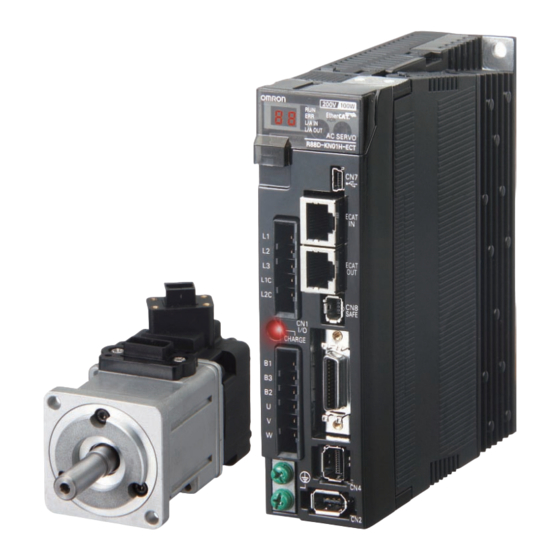
1 Features and System Configuration Names and Functions This section describes the names and functions of Servo Drive parts. 1-3-1 Servo Drive Part Names The Servo Drive part names are given below. EtherCAT status indicators Seven-segment display Analog monitor connector (CN5) Rotary switches for node address setting USB connector (CN7) -
Page 36: Servo Drive Functions
1 Features and System Configuration 1-3-2 Servo Drive Functions The functions of each part are described below. Display A 2-digit 7-segment display shows the node address, error codes, and other Servo Drive status. Charge Lamp Lights when the main circuit power supply is turned ON. EtherCAT Status Indicators These indicators show the status of EtherCAT communications. -
Page 37: System Block Diagram
1 Features and System Configuration System Block Diagram This is the block diagram of the G5-series AC Servo Drive with Built-in EtherCAT Communications. R88D-KNA5L-ECT/-KN01L-ECT/-KN02L-ECT/-KN04L-ECT/ -KN01H-ECT/-KN02H-ECT/-KN04H-ECT/-KN08H-ECT CN A CN B FUSE FUSE − Voltage detection FUSE − SW power 15 V Relay Regeneration Overcurrent... - Page 38 1 Features and System Configuration R88D-KN10H-ECT/-KN15H-ECT/-KN20H-ECT CN B CN A FUSE Internal Regeneration Resistor FUSE − Voltage detection FUSE − SW power 15 V Relay Regeneration Overcurrent Current detection supply main Gate drive drive control detection circuit control 3.3 V Display and Internal 2.5 V...
- Page 39 1 Features and System Configuration R88D-KN30H-ECT/-KN50H-ECT FUSE Internal Regeneration Resistor FUSE Voltage detection FUSE SW power supply Overcurrent Relay Regeneration Current detection Gate drive main circuit detection drive control control 3.3V Internal 2.5V Display and setting circuit 1.5V MPU & ASIC control area power supply...
- Page 40 1 Features and System Configuration R88D-KN75H-ECT FUSE Fuse FUSE − Voltage detection FUSE − SW power 15 V Relay Regeneration Overcurrent Current detection supply main Gate drive drive control detection circuit control 3.3 V Display and Internal 2.5 V setting circuit MPU &...
- Page 41 1 Features and System Configuration R88D-KN150H-ECT FUSE Fuse FUSE − Voltage detection FUSE − SW power 15 V Relay Regeneration Current detection Overcurrent supply main Gate drive drive control detection circuit control 3.3 V Display and Internal 2.5 V setting circuit MPU &...
- Page 42 1 Features and System Configuration R88D-KN06F-ECT/-KN10F-ECT/-KN15F-ECT/-KN20F-ECT CN A CN D FUSE Internal Regeneration Resistor FUSE − CN B CN C Voltage detection FUSE 24 V DC-DC − − SW power 15 V Relay Regeneration Overcurrent Current detection Gate drive supply main drive control detection...
- Page 43 1 Features and System Configuration R88D-KN30F-ECT/-KN50F-ECT FUSE Internal Regeneration Resistor FUSE − Voltage detection FUSE 24 V DC-DC − − SW power 15 V Relay Regeneration Overcurrent Current detection Gate drive supply main drive control detection circuit control 3.3 V Display and Internal 2.5 V...
- Page 44 1 Features and System Configuration R88D-KN75F-ECT FUSE Fuse FUSE − Voltage detection FUSE 24 V DC-DC − − SW power 15 V Relay Regeneration Overcurrent Current detection supply main Gate drive drive control detection circuit control 3.3 V Display and Internal 2.5 V setting circuit...
- Page 45 1 Features and System Configuration R88D-KN150F-ECT FUSE Fuse FUSE − Voltage detection FUSE 24 V DC-DC − − SW power 15 V Relay Regeneration Overcurrent Current detection supply main Gate drive drive control detection circuit control 3.3 V Display and Internal 2.5 V setting circuit...
-
Page 46: Applicable Standards
1 Features and System Configuration Applicable Standards This section describes applicable EMC Directives. 1-5-1 EC Directives Product Applicable standards Directive Low Voltage AC Servo Drives EN 61800-5-1 Directive AC Servomotors EN 60034-1/-5 AC Servo Drives EN 55011 class A group 1 Directive IEC 61800-3 EN 61000-6-2... -
Page 47: Korean Radio Regulations (Kc)
1 Features and System Configuration Servo Drive model Rated current of circuit breaker (A) R88D-KNA5L-ECT R88D-KN01L-ECT R88D-KN02L-ECT R88D-KN04L-ECT R88D-KN01H-ECT R88D-KN02H-ECT R88D-KN04H-ECT R88D-KN08H-ECT R88D-KN10H-ECT R88D-KN15H-ECT R88D-KN20H-ECT R88D-KN30H-ECT R88D-KN50H-ECT R88D-KN75H-ECT R88D-KN150H-ECT 100/125 R88D-KN06F-ECT R88D-KN10F-ECT R88D-KN15F-ECT R88D-KN20F-ECT R88D-KN30F-ECT R88D-KN50F-ECT R88D-KN75F-ECT R88D-KN150F-ECT 50/60 *1 For the use in combination with the Servomotor (Model: R88M-K11K015T- , the rated current is 100 A, and for R88M-K15K015T- , it is 125 A. -
Page 48: Unit Versions
1 Features and System Configuration Unit Versions The G5-series Servo Drive uses unit versions. Unit versions are used to manage differences in supported functions when product upgrades are made. 1-6-1 Confirmation Method The unit version of a G5-series Servo Drive is given on the product’s nameplate as shown below. Nameplate location Product Nameplate Unit Version... -
Page 49: Models And External Dimensions
Models and External Dimensions This chapter explains the models of Servo Drive, Servomotor, and peripheral devices, and provides the external dimensions and mounting dimensions. 2-1 Servo System Configuration ........2-2 2-2 How to Read Model Numbers . -
Page 50: Servo System Configuration
2 Models and External Dimensions Servo System Configuration Support Software Controller ● Automation Software Sysmac Studio NJ-series CPU Unit with EtherCAT Port Machine Automation Controller NJ501-1 00 CJ-series CPU Unit + Position Control Unit with EtherCAT Interface Support Software Support Software ●... - Page 51 Feedback Signals USB communications Encoder Cables ● Cables Standard • 750 W or less: ● G5-series Servo Drive ● G5-series Servomotor R88A-CRKA R88M-K R88D-KN -ECT • 1 kW or more: 3000r/min 100 VAC R88A-CRKC 2000r/min 200 VAC 1500r/min ● Robot Cables...
-
Page 52: How To Read Model Numbers
2 Models and External Dimensions How to Read Model Numbers This section describes how to read and understand the model numbers of Servo Drives and Servomotors. 2-2-1 Servo Drive The Servo Drive model number tells the Servo Drive type, applicable Servomotor capacity, power supply voltage, etc. -
Page 53: Servomotors
2 Models and External Dimensions 2-2-2 Servomotors The model number provides information such as the Servomotor type, motor capacity, rated rotation speed, and power supply voltage. R88M-KP10030H-B OS 2 G5-series Servomotor Motor Type Blank: Cylinder type Servomotor Capacity 050: 50 W 100: 100 W 200: 200 W 400: 400 W... -
Page 54: Reduction Gear (3 Arcminutes Max.)
2 Models and External Dimensions 2-2-3 Reduction Gear (3 Arcminutes Max.) The model number provides information such as the reduction gear, flange size number, reduction ratio, applicable Servomotor, Servomotor type, and backlash. R88G-HPG14A05100SBJ For G5-series Servomotor Reduction Gear 3 Arcminutes Max. Flange Size Number 11B: □40 14A: □60... -
Page 55: Reduction Gear (15 Arcminutes Max.)
2 Models and External Dimensions 2-2-4 Reduction Gear (15 Arcminutes Max.) The model number provides information such as the reduction gear, flange size number, reduction ratio, applicable Servomotor, Servomotor type, and backlash. R88G-VRSF09B100CJ For G5-series Servomotor Reduction Gear 15 Arcminutes Max. Reduction Ratio 05: 1/5 09: 1/9... -
Page 56: Model Tables
2 Models and External Dimensions Model Tables This section lists the standard models of Servo Drives, Servomotors, Cables, Connectors, and peripheral equipment. 2-3-1 Servo Drive Model Table The table below lists the Servo Drive models. Specifications Model Single-phase 100 VAC 50 W R88D-KNA5L-ECT 100 W... -
Page 57: Servomotor Model Tables
2 Models and External Dimensions 2-3-2 Servomotor Model Tables The following tables list the Servomotor models by the rated motor speed. 3,000-r/min Servomotors Model With incremental encoder With absolute encoder Specifications Straight shaft Straight shaft Straight shaft Straight shaft without key with key and tap without key with key and tap... - Page 58 2 Models and External Dimensions Model With incremental encoder With absolute encoder Specifications Straight shaft Straight shaft Straight shaft Straight shaft without key with key and tap without key with key and tap 100 V 50 W R88M-K05030H-B R88M-K05030H-BS2 R88M-K05030T-B R88M-K05030T-BS2 100 W R88M-K10030L-B R88M-K10030L-BS2...
- Page 59 2 Models and External Dimensions 1,500-r/min and 2,000-r/min Servomotors Model With incremental encoder With absolute encoder Specifications Straight shaft Straight shaft Straight shaft Straight shaft without key with key and tap without key with key and tap 200 V 1 kW R88M-K1K020H R88M-K1K020H-S2 R88M-K1K020T...
- Page 60 2 Models and External Dimensions Model With incremental encoder With absolute encoder Specifications Straight shaft Straight shaft Straight shaft Straight shaft without key with key and tap without key with key and tap 200 V 1 kW R88M-K1K020H-B R88M-K1K020H-BS2 R88M-K1K020T-B R88M-K1K020T-BS2 1.5 kW R88M-K1K520H-B R88M-K1K520H-BS2...
- Page 61 2 Models and External Dimensions 1,000-r/min Servomotors Model With incremental encoder With absolute encoder Specifications Straight shaft Straight shaft Straight shaft Straight shaft without key with key and tap without key with key and tap 200 V R88M-K90010H R88M-K90010H-S2 R88M-K90010T R88M-K90010T-S2 2 kW R88M-K2K010H...
-
Page 62: Servo Drive And Servomotor Combination Tables
2 Models and External Dimensions 2-3-3 Servo Drive and Servomotor Combination Tables The tables in this section show the possible combinations of G5-series Servo Drives and Servomotors. The Servomotors and Servo Drives can only be used in the listed combinations. “- ”... - Page 63 2 Models and External Dimensions 1,500-r/min and 2,000-r/min Servomotors and Servo Drives Servomotor Voltage Servo Drive Rated With incremental With absolute output encoder encoder Single-phase/ 1 kW R88M-K1K020H- R88M-K1K020T- R88D-KN10H-ECT 3-phase 200 V 1.5 kW R88M-K1K520H- R88M-K1K520T- R88D-KN15H-ECT 3-phase 200 V 2 kW R88M-K2K020H- R88M-K2K020T-...
-
Page 64: Reduction Gear Model Tables
2 Models and External Dimensions 1,000-r/min Servomotors and Servo Drives Servomotor Voltage Servo Drive Rated With incremental With absolute encoder output encoder Single-phase/ *900 W R88M-K90010H- R88M-K90010T- R88D-KN15H-ECT 3-phase 200 V 3-phase 200 V *2 kW R88M-K2K010H- R88M-K2K010T- R88D-KN30H-ECT *3 kW R88M-K3K010H- R88M-K3K010T- R88D-KN50H-ECT... - Page 65 2 Models and External Dimensions Specifications Model Servomotor Reduction capacity Ratio 400 W R88G-HPG14A05400B 1/11 R88G-HPG20A11400B 1/21 R88G-HPG20A21400B 1/33 R88G-HPG32A33400B 1/45 R88G-HPG32A45400B 750 W R88G-HPG20A05750B (200 V) 1/11 R88G-HPG20A11750B 1/21 R88G-HPG32A21750B 1/33 R88G-HPG32A33750B 1/45 R88G-HPG32A45750B 750 W R88G-HPG32A052K0B (400 V) 1/11 R88G-HPG32A112K0B 1/21...
- Page 66 2 Models and External Dimensions For 2,000-r/min Servomotors Specifications Model Servomotor Reduction capacity Ratio 400 W R88G-HPG32A052K0B 1/11 R88G-HPG32A112K0B 1/21 R88G-HPG32A211K5B 1/33 R88G-HPG32A33600SB 1/45 R88G-HPG32A45400SB 600 W R88G-HPG32A052K0B 1/11 R88G-HPG32A112K0B 1/21 R88G-HPG32A211K5B 1/33 R88G-HPG32A33600SB 1/45 R88G-HPG50A451K5B 1 kW R88G-HPG32A053K0B 1/11 R88G-HPG32A112K0SB 1/21 R88G-HPG32A211K0SB...
- Page 67 2 Models and External Dimensions For 1,000-r/min Servomotors Specifications Model Servomotor Reduction capacity Ratio 900 W R88G-HPG32A05900TB 1/11 R88G-HPG32A11900TB 1/21 R88G-HPG50A21900TB 1/33 R88G-HPG50A33900TB 2 kW R88G-HPG32A052K0TB 1/11 R88G-HPG50A112K0TB 1/21 R88G-HPG50A212K0TB 1/25 R88G-HPG65A255K0SB 3 kW R88G-HPG50A055K0SB 1/11 R88G-HPG50A115K0SB 1/20 R88G-HPG65A205K0SB 1/25 R88G-HPG65A255K0SB Note 1 The standard shaft type is a straight shaft.
-
Page 68: Cable And Peripheral Device Model Tables
2 Models and External Dimensions 2-3-5 Cable and Peripheral Device Model Tables The following tables list the models of cables and peripheral devices. The cables include motor power cables, brake cables, encoder cables, EtherCAT communications cables, and absolute encoder battery cables. - Page 69 2 Models and External Dimensions Motor Power Cables (Standard Cable) Model Specifications For motor without brake For motor with brake [100 V and 200 V] R88A-CAKA003S (See note 1.) For 3,000-r/min Servomotors of 50 to 750 W R88A-CAKA005S 10 m R88A-CAKA010S 15 m R88A-CAKA015S...
- Page 70 2 Models and External Dimensions Note 1 Different connectors are used for the motor power and the brake on 100-V and 200-V, 3,000-r/min Servomotors of 50 to 750 W and Servomotors of 6 to 15 kW. When using a Servomotor with a brake, two cables are required: a Power Cable without Brake and a Brake Cable.
- Page 71 2 Models and External Dimensions Encoder Cables (Robot Cable) Specifications Model [100 V and 200 V] R88A-CRKA003CR For 3,000-r/min Servomotors of 50 to 750 W R88A-CRKA005CR (for both absolute encoders and incremental encoders) 10 m R88A-CRKA010CR 15 m R88A-CRKA015CR 20 m R88A-CRKA020CR 30 m R88A-CRKA030CR...
- Page 72 2 Models and External Dimensions Motor Power Cables (Robot Cable) Model Specifications For motor without brake For motor with brake − [100 V and 200 V] R88A-CAKA003SR − For 3,000-r/min Servomotors of 50 to 750 W R88A-CAKA005SR − 10 m R88A-CAKA010SR −...
- Page 73 2 Models and External Dimensions Brake Cables (Robot Cable) Specifications Model [100 V and 200 V] R88A-CAKA003BR For 3,000-r/min Servomotors of 50 to 750 W R88A-CAKA005BR 10 m R88A-CAKA010BR 15 m R88A-CAKA015BR 20 m R88A-CAKA020BR 30 m R88A-CAKA030BR 40 m R88A-CAKA040BR 50 m R88A-CAKA050BR...
- Page 74 2 Models and External Dimensions Connectors Name and applications Model Motor Connector for Encoder Cable [100 V and 200 V] R88A-CNK02R For 3,000-r/min of 50 to 750 W [100 V and 200 V] R88A-CNK04R For 3,000-r/min of 1 to 5 kW For 2,000 r/min, 1,000 r/min [400 V] For 3,000 r/min, 2,000 r/min and...
- Page 75 2 Models and External Dimensions Reactor Servo Drive Reactor Number of power Model Model phases R88D-KNA5L-ECT Single-phase 3G3AX-DL2002 R88D-KN01L-ECT 3G3AX-DL2004 R88D-KN02L-ECT 3G3AX-DL2007 R88D-KN04L-ECT 3G3AX-DL2015 R88D-KN01H-ECT Single-phase 3G3AX-DL2002 Three-phase 3G3AX-AL2025 R88D-KN02H-ECT Single-phase 3G3AX-DL2004 Three-phase 3G3AX-AL2025 R88D-KN04H-ECT Single-phase 3G3AX-DL2007 Three-phase 3G3AX-AL2025 R88D-KN08H-ECT Single-phase 3G3AX-DL2015 Three-phase...
-
Page 76: External And Mounting Dimensions
2 Models and External Dimensions External and Mounting Dimensions This section describes the external dimensions and the mounting dimensions of Servo Drives, Servomotors, and peripheral devices. 2-4-1 Servo Drive Dimensions The dimensional description starts with a Servo Drive of the smallest motor capacity, which is followed by the next smallest, and so on. - Page 77 2 Models and External Dimensions Front Mounting (Using Front Mounting Brackets) External dimensions Mounting dimensions 19.5 φ5.2 2-M4 Rectangular hole (42)* * Rectangular hole dimensions are reference values. G5-series AC Servomotors and Servo Drives User’s Manual (with Built-in EtherCAT Communications) 2-29...
- Page 78 2 Models and External Dimensions Single-phase/3-phase 100 VAC: R88D-KN02L-ECT (200 W) Single-phase/3-phase 200 VAC: R88D-KN04H-ECT (400 W) Wall Mounting External dimensions Mounting dimensions 2-M4 Front Mounting (Using Front Mounting Brackets) External dimensions Mounting dimensions 19.5 2-M4 φ5.2 Rectangular hole R2.6 (57)* * Rectangular hole dimensions are reference values.
- Page 79 2 Models and External Dimensions Single-phase/3-phase 100 VAC: R88D-KN04L-ECT (400 W) Single-phase/3-phase 200 VAC: R88D-KN08H-ECT (750 W) Wall Mounting External dimensions Mounting dimensions 2-M4 Front Mounting (Using Front Mounting Brackets) External dimensions Mounting dimensions 19.5 2-M4 φ5.2 Rectangular hole R2.6 (67)* * Rectangular hole dimensions are reference values.
- Page 80 2 Models and External Dimensions Single-phase/3-phase 200 VAC: R88D-KN10H-ECT/-KN15H-ECT (900 W to 1.5 kW) Wall Mounting External dimensions Mounting dimensions 2-M4 Front Mounting (Using Front Mounting Brackets) External dimensions Mounting dimensions 19.5 4-M4 φ5.2 φ5.2 Rectangular hole R2.6 R2.6 (88)* * Rectangular hole dimensions are reference values.
- Page 81 2 Models and External Dimensions 3-phase 200 VAC: R88D-KN20H-ECT (2 kW) Wall Mounting External dimensions Mounting dimensions 17.5 φ5.2 42.5 6-M4 R2.6 R2.6 R2.6 R2.6 17.5 φ5.2 42.5 17.5 Front Mounting (Using Front Mounting Brackets) External dimensions Mounting dimensions 17.5 φ5.2 30.7 42.5...
- Page 82 2 Models and External Dimensions 3-phase 200 VAC: R88D-KN30H-ECT/-KN50H-ECT (3 to 5 kW) Wall Mounting External dimensions Mounting dimensions φ5.2 R2.6 R2.6 6-M4 R2.6 R2.6 φ5.2 Front Mounting (Using Front Mounting Brackets) External dimensions Mounting dimensions 40.7 φ5.2 R2.6 6-M4 R2.6 Rectangular hole...
- Page 83 2 Models and External Dimensions 3-phase 200 VAC: R88D-KN75H-ECT (7.5 kW) Wall Mounting External dimensions φ5.2 φ5.2 R2.6 R2.6 R2.6 R2.6 R2.6 R2.6 Mounting dimensions 10-M4 G5-series AC Servomotors and Servo Drives User’s Manual (with Built-in EtherCAT Communications) 2-35...
- Page 84 2 Models and External Dimensions Front Mounting (Using Front Mounting Brackets) External dimensions φ5.2 φ5.2 R2.6 R2.6 R2.6 R2.6 R2.6 R2.6 Mounting dimensions 10-M4 Rectangular hole (235)* * Rectangular hole dimensions are reference values. 2-36 G5-series AC Servomotors and Servo Drives User’s Manual (with Built-in EtherCAT Communications)
- Page 85 2 Models and External Dimensions 3-phase 200 VAC: R88D-KN150H-ECT (15 kW) Wall Mounting External dimensions 30.5 φ7 φ7 30.5 R3.5 R3.5 Mounting dimensions 30.5 4-M6 G5-series AC Servomotors and Servo Drives User’s Manual (with Built-in EtherCAT Communications) 2-37...
- Page 86 2 Models and External Dimensions 3-phase 400 VAC: R88D-KN06F-ECT/-KN10F-ECT (600 W to 1.0 kW) 3-phase 400 VAC: R88D-KN15F-ECT (1.5 kW) Wall Mounting External dimensions Mounting dimensions 2-M4 14.5 Front Mounting (Using Front Mounting Brackets) External dimensions Mounting dimensions 19.5 4-M4 φ5.2 φ5.2 Rectangular...
- Page 87 2 Models and External Dimensions 3-phase 400 VAC: R88D-KN20F-ECT (2 kW) Wall Mounting External dimensions Mounting dimensions 17.5 Ø5.2 42.5 6-M4 R2.6 R2.6 26.5 Ø5.2 17.5 Front Mounting (Using Front Mounting Brackets) External dimensions Mounting dimensions 17.5 Ø5.2 42.5 30.7 6-M4 Rectangular hole...
- Page 88 2 Models and External Dimensions 3-phase 400 VAC: R88D-KN30F-ECT/-KN50F-ECT (3 to 5 kW) Wall Mounting External dimensions Mounting dimensions 6-M4 Ø5.2 R2.6 R2.6 Ø5.2 Front Mounting (Using Front Mounting Brackets) External dimensions Mounting dimensions 6-M4 φ5.2 40.7 Rectangular hole R2.6 R2.6 (132)* φ5.2...
- Page 89 2 Models and External Dimensions 3-phase 400 VAC: R88D-KN75F-ECT (7.5 kW) Wall Mounting External dimensions Ø Ø R2.6 R2.6 R2.6 R2.6 R2.6 R2.6 Ø Ø Mounting dimensions 10-M4 G5-series AC Servomotors and Servo Drives User’s Manual (with Built-in EtherCAT Communications) 2-41...
- Page 90 2 Models and External Dimensions Front Mounting (Using Front Mounting Brackets) External dimensions Ø Ø R2.6 R2.6 R2.6 R2.6 R2.6 R2.6 Ø Ø Mounting dimensions 10-M4 Rectangular hole (235)* * Rectangular hole dimensions are reference values. 2-42 G5-series AC Servomotors and Servo Drives User’s Manual (with Built-in EtherCAT Communications)
- Page 91 2 Models and External Dimensions 3-phase 400 VAC: R88D-KN150F-ECT (15 kW) Wall Mounting External dimensions 30.5 Ø7 Ø7 R3.5 R3.5 30.5 Mounting dimensions 30.5 4-M6 G5-series AC Servomotors and Servo Drives User’s Manual (with Built-in EtherCAT Communications) 2-43...
-
Page 92: Servomotor Dimensions
2 Models and External Dimensions 2-4-2 Servomotor Dimensions In this description, the Servomotors are grouped by rated rotation speed. The description starts with a Servomotor of the smallest capacity, which is followed by the next smallest, and so on. 3,000-r/min Servomotors (100 V and 200 V) 50 W/100 W (without Brake) R88M-K05030H (-S2)/-K10030 (-S2) - Page 93 2 Models and External Dimensions 50 W/100 W (with Brake) R88M-K05030H-B (S2)/-K10030 -B (S2) R88M-K05030T-B (S2)/-K10030 -B (S2) Encoder connector Brake connector Motor connector 40×40 (Shaft end specifications with key and tap) 12.5 46.6 R3.7 M3 (depth 6) R4.2 2-φ4.3 Dimensions (mm) Model R88M-K05030 -B...
- Page 94 2 Models and External Dimensions 200 W/400 W (with Brake) R88M-K20030 -B (S2)/-K40030 -B (S2) R88M-K20030 -B (S2)/-K40030 -B (S2) Encoder connector Brake connector Motor connector 60×60 4-φ4.5 (Shaft end specifications with key and tap) 30 20 (200 W) 25 (400 W) 52.5 4h9 (200 W) 18 (200 W)
- Page 95 2 Models and External Dimensions 750 W (with Brake) R88M-K75030H-B (S2) R88M-K75030T-B (S2) Encoder connector Brake connector Motor connector 148.2 122.2 80×80 (Shaft end specifications with key and tap) 4-φ6 61.6 M5 (depth 10) Note The standard models have a straight shaft. Models with a key and tap are indicated with S2 at the end of the model number.
- Page 96 2 Models and External Dimensions Note The standard models have a straight shaft. Models with a key and tap are indicated with S2 at the end of the model number. Models with an oil seal are indicated with O at the end of the model number. The motor dimensions do not change.
- Page 97 2 Models and External Dimensions 4 kW/5 kW (without Brake) R88M-K4K030H (-S2)/-K5K030H (-S2) R88M-K4K030T (-S2)/-K5K030T (-S2) 4 kW/5 kW (with Brake) R88M-K4K030H-B (S2)/-K5K030H-B (S2) R88M-K4K030T-B (S2)/-K5K030T-B (S2) Motor and brake connector (Shaft end specifications with key and tap) Encoder 130×130 connector 4−φ9 M3, through...
- Page 98 2 Models and External Dimensions 3,000-r/min Servomotors (400 V) 750 W/1 kW/1.5 kW/2 kW (without Brake) R88M-K75030F (-S2)/-K1K030F (-S2)/-K1K530F (-S2)/-K2K030F (-S2) R88M-K75030C (-S2)/-K1K030C (-S2)/-K1K530C (-S2)/-K2K030C (-S2) 750 W/1 kW/1.5 kW/2 kW (with Brake) R88M-K75030F-B (S2)/-K1K030F-B (S2)/-K1K530F-B (S2)/-K2K030F-B (-S2) R88M-K75030C-B (S2)/-K1K030C-B (S2)/-K1K530C-B (S2)/-K2K030C-B (-S2) Motor and brake connector Encoder...
- Page 99 2 Models and External Dimensions 3 kW (without Brake) R88M-K3K030F (-S2) R88M-K3K030C (-S2) 3 kW (with Brake) R88M-K3K030F-B (S2) R88M-K3K030C-B (S2) Motor and brake connector (Shaft end specifications with key and tap) 120×120 Encoder connector 4-φ9 M3, through M5 (depth 12) Dimensions (mm) Model R88M-K3K030...
- Page 100 2 Models and External Dimensions 4 kW/5 kW (without Brake) R88M-K4K030F (-S2)/-K5K030F (-S2) R88M-K4K030C (-S2)/-K5K030C (-S2) 4 kW/5 kW (with Brake) R88M-K4K030F-B (S2)/-K5K030F-B (S2) R88M-K4K030C-B (S2)/-K5K030C-B (S2) Motor and brake connector (Shaft end specifications with key and tap) Encoder 130×130 connector 4−φ9 M3, through...
- Page 101 2 Models and External Dimensions 1,500-r/min and 2,000-r/min Servomotors (200 V) 1 kW/1.5 kW/2 kW/3 kW (without Brake) R88M-K1K020H (-S2)/-K1K520H (-S2)/-K2K020H (-S2)/-K3K020H (-S2) R88M-K1K020T (-S2)/-K1K520T (-S2)/-K2K020T (-S2)/-K3K020T (-S2) 1 kW/1.5 kW/2 kW/3 kW (with Brake) R88M-K1K020H-B (S2)/-K1K520H-B (S2)/-K2K020H-B (S2)/-K3K020H-B (S2) R88M-K1K020T-B (S2)/-K1K520T-B (S2)/-K2K020T-B (S2)/-K3K020T-B (S2) Motor and brake connector...
- Page 102 2 Models and External Dimensions 4 kW/5 kW (without Brake) R88M-K4K020H (-S2)/-K5K020H (-S2) R88M-K4K020T (-S2)/-K5K020T (-S2) 4 kW/5 kW (with Brake) R88M-K4K020H-B (S2)/-K5K020H-B (S2) R88M-K4K020T-B (S2)/-K5K020T-B (S2) Motor and brake connector (Shaft end specifications with key and tap) 176×176 Encoder connector 4−φ13.5 M3, through...
- Page 103 2 Models and External Dimensions 7.5 kW (without Brake) R88M-K7K515T (-S2) 7.5 kW (with Brake) R88M-K7K515T-B (S2) Motor connector Brake connector (for model with brake only) 176 × 176 Encoder connector 43.5 43.5 (Shaft end specifications with key and tap) 4-φ13.5 M4, through 12h9...
- Page 104 2 Models and External Dimensions 11 kW/15 kW (without Brake) R88M-K11K015T (-S2)/-K15K015T (-S2) 11 kW/15 kW (with Brake) R88M-K11K015T-B (S2)/R88M-K15K015T-B (S2) Motor Brake connector connector (for model with brake only) 220 × 220 Encoder connector 4-φ13.5 (Shaft end specifications with key and tap) 16h9 through (Key groove P9)
- Page 105 2 Models and External Dimensions 1,500-r/min and 2,000-r/min Servomotors (400 V) 400 W/600 W (without Brake) R88M-K40020F (-S2)/-K60020F (-S2) R88M-K40020C (-S2)/-K60020C (-S2) 400 W/600 W (with Brake) R88M-K40020F-B (S2)/-K60020F-B (S2) R88M-K40020C-B (S2)/-K60020C-B (S2) Motor and brake connector Encoder connector 100×100 (Shaft end specifications with key and tap) M3, through 4-φ9...
- Page 106 2 Models and External Dimensions 1 kW/1.5 kW/2 kW/3 kW (without Brake) R88M-K1K020F (-S2)/-K1K520F (-S2)/-K2K020F (-S2)/-K3K020F (-S2) R88M-K1K020C (-S2)/-K1K520C (-S2)/-K2K020C (-S2)/-K3K020C (-S2) 1 kW/1.5 kW/2 kW/3 kW (with Brake) R88M-K1K020F-B (S2)/-K1K520F-B (S2)/-K2K020F-B (S2)/-K3K020F-B (S2) R88M-K1K020C-B (S2)/-K1K520C-B (S2)/-K2K020C-B (S2)/-K3K020C-B (S2) Motor and brake connector (Shaft end specifications with key and tap) 130×130...
- Page 107 2 Models and External Dimensions 4 kW/5 kW (without Brake) R88M-K4K020F (-S2)/-K5K020F (-S2) R88M-K4K020C (-S2)/-K5K020C (-S2) 4 kW/5 kW (with Brake) R88M-K4K020F-B (S2)/-K5K020F-B (S2) R88M-K4K020C-B (S2)/-K5K020C-B (S2) Motor and brake connector Encoder 176×176 (Shaft end specifications with key and tap) connector 4-φ13.5 M3, through...
- Page 108 2 Models and External Dimensions 7.5 kW (without Brake) R88M-K7K515C (-S2) 7.5 kW (with Brake) R88M-K7K515C-B (S2) Motor Brake connector connector (for model with brake only) Encoder 176 × 176 connector 43.5 43.5 (Shaft end specifications with key and tap) 4-φ13.5 M4, through 12h9...
- Page 109 2 Models and External Dimensions 11 kW/15 kW (without Brake) R88M-K11K015C (-S2)/-K15K015C (-S2) 11 kW/15 kW (with Brake) R88M-K11K015C-B (S2)/R88M-K15K015C-B (S2) Brake connector Motor (for model with brake only) connector 220 × 220 Encoder connector 4-φ13.5 (Shaft end specifications with key and tap) 16h9 through (Key groove P9)
- Page 110 2 Models and External Dimensions 1,000-r/min Servomotors (200 V) 900 W (without Brake) R88M-K90010H (-S2) R88M-K90010T (-S2) 900 W (with Brake) R88M-K90010H-B (S2) R88M-K90010T-B (S2) Motor and brake connector Encoder 130×130 (Shaft end specifications with key and tap) connector 77.5 4-φ9 M3, through M5 (depth 12)
- Page 111 2 Models and External Dimensions 2 kW/3 kW (without Brake) R88M-K2K010H (-S2)/-K3K010H (-S2) R88M-K2K010T (-S2)/-K3K010T (-S2) 2 kW/3 kW (with Brake) R88M-K2K010H-B (S2)/-K3K010H-B (S2) R88M/-K2K010T-B (S2)/-K3K010T-B (S2) Motor and brake connector 176×176 Encoder (Shaft end specifications with key and tap) connector 4−φ13.5 M3, through...
- Page 112 2 Models and External Dimensions 4.5 kW (without Brake) R88M-K4K510T (-S2) 4.5 kW (with Brake) R88M-K4K510T-B (S2) 176 × 176 Motor and brake connector 43.5 43.5 Encoder connector (Shaft end specifications with key and tap) 4-φ13.5 M4, through 12h9 (Key groove P9) 2 min.
- Page 113 2 Models and External Dimensions 6 kW (without Brake) R88M-K6K010T (-S2) 6 kW (with Brake) R88M-K6K010T-B (S2) Motor connector Brake connector (for model with brake only) Encoder 176 × 176 connector 43.5 43.5 (Shaft end specifications with key and tap) 4-φ13.5 M4, through 12h9...
- Page 114 2 Models and External Dimensions 1,000-r/min Servomotors (400 V) 900 W (without Brake) R88M-K90010F (-S2) R88M-K90010C (-S2) 900 W (with Brake) R88M-K90010F-B (S2) R88M-K90010C-B (S2) Motor and brake connector Encoder 130×130 (Shaft end specifications with key and tap) connector 4-φ9 M3, through M5 (depth 12) Dimensions (mm)
- Page 115 2 Models and External Dimensions 2 kW/3 kW (without Brake) R88M-K2K010F (-S2)/-K3K010F (-S2) R88M-K2K010C (-S2)/-K3K010C (-S2) 2 kW/3 kW (with Brake) R88M-K2K010F-B (S2)/-K3K010F-B (S2) R88M-K2K010C-B (S2)/-K3K010C-B (S2) Motor and brake connector (Shaft end specifications with key and tap) Encoder 176×176 connector 4−φ13.5 M3, through...
- Page 116 2 Models and External Dimensions 4.5 kW (without Brake) R88M-K4K510C (-S2) 4.5 kW (with Brake) R88M-K4K510C-B (S2) 176 × 176 Motor and brake connector 43.5 43.5 Encoder connector (Shaft end specifications with key and tap) 4-φ13.5 M4, through 12h9 (Key groove P9) 2 min.
- Page 117 2 Models and External Dimensions 6 kW (without Brake) R88M-K6K010C (-S2) 6 kW (with Brake) R88M-K6K010C-B (S2) Motor connector Brake connector (for model with brake only) 176 × 176 Encoder connector 43.5 43.5 (Shaft end specifications with key and tap) 4-φ13.5 M4, through 12h9...
-
Page 118: Combinations Of Servomotors And Reduction Gears
2 Models and External Dimensions 2-4-3 Combinations of Servomotors and Reduction Gears The tables in this section show the possible combinations of Servomotors and Reduction Gears by the rated motor rotation speed. 3,000-r/min Servomotors Servomotor 1/11 1/21 1/33 1/45 models (1/9 for flange 11) R88M- R88G-... - Page 119 2 Models and External Dimensions 2,000-r/min Servomotors Servomotor 1/21 1/33 1/11 1/45 models (1/20 for flange 65) (1/25 for flange 65) R88M- R88G- R88G- R88G- R88G- R88G- K40020 HPG32A052K0B HPG32A112K0B HPG32A211K5B HPG32A33600SB HPG32A45400SB (only for 400 V) (for both with (for both with (for both with (for both with...
-
Page 120: Reduction Gear Dimensions
2 Models and External Dimensions 2-4-4 Reduction Gear Dimensions 3 Arcminutes Max. For 3,000-r/min Servomotors (50 to 200 W) Dimensions (mm) External Model view 50 W R88G-HPG11B05100B 39.5 39.5 R88G-HPG11B09050B 39.5 39.5 R88G-HPG14A21100B 1/21 64.0 55.5 R88G-HPG14A33050B 1/33 64.0 55.5 R88G-HPG14A45050B 1/45 64.0... - Page 121 2 Models and External Dimensions Dimensions (mm) Model AT*1 R88G-HPG11B05100B 50 W M4 × 9 R88G-HPG11B09050B M4 × 9 R88G-HPG14A21100B M4 × 10 1/21 R88G-HPG14A33050B M4 × 10 1/33 R88G-HPG14A45050B M4 × 10 1/45 R88G-HPG11B05100B 100 W M4 × 9 R88G-HPG14A11100B M4 ×...
- Page 122 2 Models and External Dimensions For 3,000-r/min Servomotors (400 to 750 W) Dimensions (mm) External Model view 400 W R88G-HPG14A05400B 55.5 R88G-HPG20A11400B 1/11 ø89 R88G-HPG20A21400B 1/21 ø89 R88G-HPG32A33400B 1/33 ø122 12.5 R88G-HPG32A45400B 1/45 ø122 12.5 750 W R88G-HPG20A05750B (200 V) R88G-HPG20A11750B 1/11 R88G-HPG32A21750B...
- Page 123 2 Models and External Dimensions Dimensions (mm) Model R88G-HPG14A05400B 400 W M4 × 10 R88G-HPG20A11400B M4 × 10 1/11 R88G-HPG20A21400B M4 × 10 1/21 R88G-HPG32A33400B M4 × 10 1/33 R88G-HPG32A45400B M4 × 10 1/45 R88G-HPG20A05750B 750 W M5 × 12 (200 V) R88G-HPG20A11750B M5 ×...
- Page 124 2 Models and External Dimensions For 3,000-r/min Servomotors (1 kW to 5 kW) Dimensions (mm) External Model view 1 kW R88G-HPG32A052K0B ø135 12.5 R88G-HPG32A112K0B 1/11 ø135 12.5 R88G-HPG32A211K5B 1/21 ø135 12.5 R88G-HPG50A332K0B 1/33 ø170 R88G-HPG50A451K5B 1/45 ø170 1.5 kW R88G-HPG32A052K0B ø135 12.5 R88G-HPG32A112K0B...
- Page 125 2 Models and External Dimensions Dimensions (mm) Model R88G-HPG32A052K0B 1 kW M8 × 10 R88G-HPG32A112K0B M8 × 10 1/11 R88G-HPG32A211K5B M8 × 10 1/21 R88G-HPG50A332K0B M8 × 10 1/33 R88G-HPG50A451K5B M8 × 10 1/45 R88G-HPG32A052K0B 1.5 kW M8 × 10 R88G-HPG32A112K0B M8 ×...
- Page 126 2 Models and External Dimensions For 2,000-r/min Servomotors (400 W to 1 kW) Dimensions (mm) External Model view 400 W R88G-HPG32A052K0B ø135 12.5 (400 V) R88G-HPG32A112K0B 1/11 ø135 12.5 R88G-HPG32A211K5B 1/21 ø135 12.5 R88G-HPG32A33600SB 1/33 ø135 12.5 R88G-HPG32A45400SB 1/45 ø135 12.5 600 W R88G-HPG32A052K0B...
- Page 127 2 Models and External Dimensions Dimensions (mm) Model R88G-HPG32A052K0B 400 W M8 × 10 (400 V) R88G-HPG32A112K0B M8 × 10 1/11 R88G-HPG32A211K5B M8 × 10 1/21 R88G-HPG32A33600SB M8 × 10 1/33 R88G-HPG32A45400SB M8 × 10 1/45 R88G-HPG32A052K0B 600 W M8 × 10 (400 V) R88G-HPG32A112K0B M8 ×...
- Page 128 2 Models and External Dimensions For 2,000-r/min Servomotors (1.5 kW to 5 kW) Dimensions (mm) External Model view 1.5 kW R88G-HPG32A053K0B 12.5 1/11 R88G-HPG32A112K0SB 12.5 R88G-HPG50A213K0B 1/21 ø170 1/33 R88G-HPG50A332K0SB ø170 2 kW R88G-HPG32A053K0B 12.5 1/11 R88G-HPG32A112K0SB 12.5 1/21 R88G-HPG50A213K0B ø170 R88G-HPG50A332K0SB 1/33...
- Page 129 2 Models and External Dimensions Dimensions (mm) Model R88G-HPG32A053K0B 1.5 kW M8 × 18 R88G-HPG32A112K0SB M8 × 18 1/11 R88G-HPG50A213K0B M8 × 16 1/21 R88G-HPG50A332K0SB M8 × 16 1/33 R88G-HPG32A053K0B 2 kW M8 × 18 R88G-HPG32A112K0SB M8 × 18 1/11 R88G-HPG50A213K0B M8 ×...
- Page 130 2 Models and External Dimensions For 1,000-r/min Servomotors (900 W to 3 kW) Dimensions (mm) External Model view 900 W R88G-HPG32A05900TB 12.5 R88G-HPG32A11900TB 1/11 12.5 R88G-HPG50A21900TB 1/21 R88G-HPG50A33900TB 1/33 2 kW R88G-HPG32A052K0TB 12.5 R88G-HPG50A112K0TB 1/11 R88G-HPG50A212K0TB 1/21 R88G-HPG65A255K0SB 1/25 3 kW R88G-HPG50A055K0SB R88G-HPG50A115K0SB 1/11...
- Page 131 2 Models and External Dimensions Dimensions (mm) Model R88G-HPG32A05900TB 900 W M8 × 25 R88G-HPG32A11900TB M8 × 25 1/11 R88G-HPG50A21900TB M8 × 25 1/21 R88G-HPG50A33900TB M8 × 25 1/33 R88G-HPG32A052K0TB 2 kW M12 × 25 R88G-HPG50A112K0TB M12 × 25 1/11 R88G-HPG50A212K0TB M12 ×...
- Page 132 2 Models and External Dimensions 15 Arcminutes Max. For 3,000-r/min Servomotors Dimensions (mm) Model 50 W R88G-VRSF05B100CJ 67.5 R88G-VRSF09B100CJ 67.5 1/15 R88G-VRSF15B100CJ 78.0 1/25 R88G-VRSF25B100CJ 78.0 100 W R88G-VRSF05B100CJ 67.5 R88G-VRSF09B100CJ 67.5 1/15 R88G-VRSF15B100CJ 78.0 1/25 R88G-VRSF25B100CJ 78.0 200 W R88G-VRSF05B200CJ 72.5 R88G-VRSF09C200CJ...
- Page 133 2 Models and External Dimensions Dimensions (mm) Model R88G-VRSF05B100CJ 50 W R88G-VRSF09B100CJ R88G-VRSF15B100CJ 1/15 R88G-VRSF25B100CJ 1/25 R88G-VRSF05B100CJ 100 W R88G-VRSF09B100CJ R88G-VRSF15B100CJ 1/15 R88G-VRSF25B100CJ 1/25 R88G-VRSF05B200CJ 200 W R88G-VRSF09C200CJ R88G-VRSF15C200CJ 1/15 R88G-VRSF25C200CJ 1/25 R88G-VRSF05C400CJ 400 W R88G-VRSF09C400CJ R88G-VRSF15C400CJ 1/15 R88G-VRSF25C400CJ 1/25 R88G-VRSF05C750CJ 750 W R88G-VRSF09D750CJ...
-
Page 134: External Regeneration Resistor Dimensions
2 Models and External Dimensions 2-4-5 External Regeneration Resistor Dimensions External Regeneration Resistor R88A-RR08050S/-RR080100S Thermal switch output t1.2 R88A-RR22047S1 Thermal switch output t1.2 R88A-RR50020S 2-86 G5-series AC Servomotors and Servo Drives User’s Manual (with Built-in EtherCAT Communications) -
Page 135: Reactor Dimensions
2 Models and External Dimensions 2-4-6 Reactor Dimensions 3G3AX-DL2002 2-M4 Ground terminal (M4) 4-5.2 × 8 3G3AX-DL2004 2-M4 Ground terminal (M4) 4-5.2 × 8 G5-series AC Servomotors and Servo Drives User’s Manual (with Built-in EtherCAT Communications) 2-87... - Page 136 2 Models and External Dimensions 3G3AX-DL2007 2-M4 Ground terminal (M4) 4-5.2 × 8 3G3AX-DL2015 2-M4 Ground terminal (M4) 4-5.2 × 8 2-88 G5-series AC Servomotors and Servo Drives User’s Manual (with Built-in EtherCAT Communications)
- Page 137 2 Models and External Dimensions 3G3AX-DL2022 2-M4 Ground terminal (M4) 4-6 × 9 3G3AX-AL2025/-AL2055/-AL4025/-AL4055 Ground terminal (M5) Terminal screw 6- Ø Terminal block Ro R So S To T Ro R So S To Connection Diagram Ø Y±1 50±1 (Cutout) Dimensions (mm) Model 3G3AX-AL2025...
- Page 138 2 Models and External Dimensions 3G3AX-AL2110/-AL2220/-AL4110/-AL4220 Terminal hole 6- Ø Ro R So S To T R So S To Connection Diagram X±1 Y±1 Ø W= Terminal width (Cutout) Ground terminal (M6) Dimensions (mm) Model 3G3AX-AL2110 3G3AX-AL2220 16.5 3G3AX-AL4110 12.5 3G3AX-AL4220 2-90 G5-series AC Servomotors and Servo Drives User’s Manual (with Built-in EtherCAT Communications)
-
Page 139: Mounting Bracket (L-Brackets For Rack Mounting) Dimensions
2 Models and External Dimensions 2-4-7 Mounting Bracket (L-brackets for Rack Mounting) Dimensions R88A-TK01K Mounting bracket for top side Mounting bracket for bottom side 2-M4 countersunk 2-M4 countersunk 11± 0.2 11± 0.2 R88A-TK02K Mounting bracket for top side Mounting bracket for bottom side 2-M4 countersunk 2-M4 countersunk 18±0.2... - Page 140 2 Models and External Dimensions R88A-TK04K Mounting bracket for top side Mounting bracket for bottom side 2-M4 countersunk 2-M4 countersunk 36± 0.2 36± 0.2 40±0.2 40±0.2 2-92 G5-series AC Servomotors and Servo Drives User’s Manual (with Built-in EtherCAT Communications)
-
Page 141: Specifications
Specifications This chapter provides the general specifications, characteristics, connector specifications, and I/O circuits of the Servo Drives as well as the general specifications, characteristics, encoder specifications of the Servomotors and other peripheral devices. 3-1 Servo Drive Specifications........3-2 3-1-1 General Specifications . -
Page 142: Servo Drive Specifications
3 Specifications Servo Drive Specifications Select a Servo Drive that matches the Servomotor to be used. Refer to 2-3-3 Servo Drive and Servomotor Combination Tables on page 2-14. 3-1-1 General Specifications Item Specifications Ambient operating temperature and 0 to 55°C, 90% max. (with no condensation) operating humidity −20 to 65°C, 90% max. -
Page 143: Characteristics
3 Specifications 3-1-2 Characteristics 100-VAC Input Models R88D- R88D- R88D- R88D- Item KNA5L-ECT KN01L-ECT KN02L-ECT KN04L-ECT Continuous output current (rms) 1.2 A 1.7 A 2.5 A 4.6 A Input power Main Power 0.4 KVA 0.4 KVA 0.5 KVA 0.9 KVA supply circuit supply... - Page 144 3 Specifications 200-VAC Input Models R88D- R88D- R88D- R88D- R88D- R88D- Item KN01H-ECT KN02H-ECT KN04H-ECT KN08H-ECT KN10H-ECT KN15H-ECT Continuous output current (rms) 1.2 A 1.6 A 2.6 A 4.1 A 5.9 A 9.4 A Input power Main Power 0.5 KVA 0.5 KVA 0.9 KVA 1.3 KVA...
- Page 145 3 Specifications R88D- R88D- R88D- R88D- R88D- Item KN150H- KN20H-ECT KN30H-ECT KN50H-ECT KN75H-ECT Continuous output current (rms) 13.4 A 18.7 A 33.0 A 44.0 A 66.1 A Input power Main Power 3.3 KVA 4.5 KVA 7.5 KVA 11.0 KVA 22.0 KVA supply circuit supply...
- Page 146 3 Specifications 400-VAC Input Models R88D- R88D- R88D- R88D- R88D- R88D- R88D- R88D- Item KN06F-ECT KN10F-ECT KN15F-ECT KN20F-ECT KN30F-ECT KN50F-ECT KN75F-ECT KN150F-ECT Continuous output current (rms) 1.5 A 2.9 A 4.7 A 6.7 A 9.4 A 16.5 A 22.0 A 33.1 A Input power Main...
-
Page 147: Ethercat Communications Specifications
3 Specifications 3-1-3 EtherCAT Communications Specifications Item Specification Communications standard IEC 61158 Type 12, IEC 61800-7 CiA 402 Drive Profile Physical layer 100BASE-TX (IEEE802.3) RJ45 × 2 (shielded) Connectors ECAT IN: EtherCAT input ECAT OUT: EtherCAT output Communications media Ethernet Category 5 (100BASE-TX) or higher (twisted-pair cable with double, aluminum tape and braided shielding) is recommended. -
Page 148: Main Circuit And Motor Connections
3 Specifications 3-1-4 Main Circuit and Motor Connections When wiring the main circuit, use proper wire sizes, grounding systems, and noise resistance. R88D-KNA5L-ECT/-KN01L-ECT/-KN02L-ECT/-KN04L-ECT/ -KN01H-ECT/-KN02H-ECT/-KN04H-ECT/-KN08H-ECT/ -KN10H-ECT/-KN15H-ECT Main Circuit Connector Specifications (CNA) Symbol Name Function Main circuit power R88D-KN L-ECT supply input 50 to 400 W: Single-phase 100 to 120 VAC (85 to 132 V) 50/60 Hz R88D-KN H-ECT 100 W to 1.5 kW: Single-phase: 200 to 240 VAC (170 to 264 V) 50/60 Hz... - Page 149 3 Specifications R88D-KN20H-ECT Main Circuit Connector Specifications (CNA) Symbol Name Function Main circuit power R88D-KN H-ECT (2 kW) : supply input 3-phase: 200 to 230 VAC (170 to 253 VAC) 50/60 Hz Control circuit power R88D-KN H-ECT: Single-phase 200 to 230 VAC (170 to 253 VAC) 50/60 supply input Motor Connector Specifications (CNB) Symbol...
- Page 150 3 Specifications R88D-KN30H-ECT/R88D-KN50H-ECT Main Circuit Terminal Block Specifications Symbol Name Function Main circuit power R88D-KN H-ECT (3 to 5 kW): supply input 3-phase 200 to 230 VAC (170 to 253 VAC) 50/60 Hz Control circuit power R88D-KN H-ECT : Single-phase 200 to 230 VAC (170 to 253 VAC) 50/60 supply input External Regeneration Normally B2 and B3 are shorted.
- Page 151 3 Specifications R88D-KN75H-ECT Terminal Block Specifications, Left Terminal Block (TB1) Symbol Name Function Main circuit power R88D-KN H-ECT (7.5 kW): supply input 3-phase 200 to 230 VAC (170 to 253 VAC) 50/60 Hz 280 to 325 VDC (238 to 357 VDC) External Regeneration Connect an External Regeneration Resistor between B1 and B2.
- Page 152 3 Specifications R88D-KN150H-ECT Terminal Block Specifications, Top Terminal Block (TB1) Symbol Name Function Control circuit power R88D-KN H-ECT: supply input Single-phase 200 to 230 VAC (170 to 253 VAC) 50/60 Hz 280 to 325 VDC (238 to 357 VDC) Dynamic Brake Resistor These terminals are used to control the MC for externally connected control terminals dynamic brake resistance.
- Page 153 3 Specifications R88D-KN06F-ECT/-KN10F-ECT/-KN15F-ECT/-KN20F-ECT Main Circuit Connector Specifications (CNA) Symbol Name Function Main circuit power R88D-KN F-ECT supply input 600 W to 1.5 kW: 3-phase: 380 to 480 VAC (323 to 528 VAC) 50/60 Hz Motor Connector Specifications (CNB) Symbol Name Function Motor connection Phase U...
- Page 154 3 Specifications R88D-KN30F-ECT/R88D-KN50F-ECT Main Circuit Terminal Block Specifications (TB1) Symbol Name Function 24 V Control circuit power 24 VDC ± 15% supply input Main Circuit Terminal Block Specifications (TB2) Symbol Name Function Main circuit power R88D-KN F-ECT (3 to 5 kW): supply input 3-phase 380 to 480 VAC (323 to 528 VAC) 50/60 Hz External Regeneration...
- Page 155 3 Specifications R88D-KN75F-ECT Terminal Block Specifications, Left Terminal Block (TB1) Symbol Name Function Main circuit power R88D-KN F-ECT (7.5 kW): supply input 3-phase 380 to 480 VAC (323 to 528 VAC) 50/60 Hz External Regeneration Connect an External Regeneration Resistor between B1 and B2. Resistor connection terminals Do not connect.
- Page 156 3 Specifications R88D-KN150F-ECT Terminal Block Specifications, Top Terminal Block (TB1) Symbol Name Function 24 VDC ±15% 24 V Control circuit power supply input Dynamic Brake Resistor These terminals are used to control the MC for externally connected control terminals dynamic brake resistance. The output contact specifications are 1 A max. at 300 VAC/100 VDC max.
-
Page 157: Ethercat Communications Connector Specifications (Rj45)
3 Specifications 3-1-5 EtherCAT Communications Connector Specifications (RJ45) The EtherCAT twisted-pair cable is connected to a shielded connector. • Electrical characteristics: Confirm to IEEE 802.3. • Connector structure: RJ45 8-pin modular connector (conforms to ISO 8877) Pin No. Signal name Abbreviation Direction Send data +... -
Page 158: Control I/O Connector Specifications (Cn1)
3 Specifications 3-1-6 Control I/O Connector Specifications (CN1) Control I/O Signal Connections and External Signal Processing 4.7 kΩ /ALM 12 to 24 VDC +24 VIN 10 Ω Error output Maximum ALMCOM General-purpose service 1 kΩ input 1 voltage: OUTM1 30 VDC 10 Ω... - Page 159 3 Specifications Control I/O Signal Tables CN1 Control Inputs Signal Symbol Function and interface number Name Default +24 VIN Power supply input 12 to 24 VDC. The positive input terminal of the external power supply (12 to 24 VDC) for sequence inputs General-purpose Immediate Stop...
- Page 160 To use an absolute encoder, connect a battery to pin 14 and 15, which is the backup battery input, or connect the battery to the holder of the absolute encoder cable. (Never connect to both.) Connectors for CN1 (Pin 26) Name Model Manufacturer OMRON model number Plug 10126-3000PE Sumitomo 3M R88A-CNW01C Cable Case...
-
Page 161: Control Input Circuits
3 Specifications 3-1-7 Control Input Circuits External power supply 4.7 kΩ +24VIN 12 VDC ± 5% to 24 VDC ± 5% 1.0 kΩ Photocoupler input Power supply capacity 50 mA or more (per unit) 4.7 kΩ Signal level 1.0 kΩ Photocoupler input ON level: 10 V or more OFF level: 3 V or less... - Page 162 3 Specifications Forward Drive Prohibition Input (POT) and Reverse Drive Prohibition Input (NOT) • These two signals are the inputs to prohibit forward and reverse rotation (over-travel inputs). • When these terminals are shorted (factory setting), the Servo Drive can rotate in the specified direction.
-
Page 163: Control Output Circuits
3 Specifications Monitor Inputs (MON0, MON1, and MON2) • These are the general-purpose monitor inputs. • The general-purpose monitor inputs do not affect operation and can be monitored from the host controller. • With the default settings, MON0 is allocated to pin 13. Forward External Torque Limit Input (PCL) and Reverse External Torque Limit Input (NCL) •... -
Page 164: Control Output Details
3 Specifications 3-1-10 Control Output Details Control Output Sequence The chart below illustrates the timing of the command inputs after the control power supply is turned ON. Input the Servo ON/OFF operation, position, speed, and torque commands in the correct timing, as shown in the chart. - Page 165 3 Specifications Error Output (/ALM) Pin 3: Error Output (/ALM) Pin 4: Error Output Common (ALMCOM) Function • This output is turned OFF when the drive detects an error. • This output is OFF when the power supply is turned ON, but turns ON when the drive's initial processing has been completed.
- Page 166 3 Specifications Motor rotation speed [r/min] Motor rotation speed 3436 hex + 10 3436 hex − 10 Time − (3436 hex − 10) − (3436 hex + 10) Motor Rotation Speed Detection Output (TGON) Torque Limit Output (TLIMT) • The output turns ON when the output torque reaches the limit set in the Positive torque limit value (60E0 hex) or the Negative torque limit value (60E1 hex).
- Page 167 3 Specifications Speed command after acceleration or Speed Conformity deceleration process Speed command Detection Range (3435 hex) Rotation speed [r/min] Motor rotation speed Speed Conformity Detection Range (3435 hex) Time Speed Conformity Detection Range (3435 hex) Speed Conformity Output (VCMP) Warning Outputs (WARN1 and WARN2) •...
-
Page 168: Encoder Connector Specifications (Cn2)
Encoder − phase S input PS− Shell Frame ground Frame ground Connectors for CN2 (6 Pins) Name Model Manufacturer OMRON model number − Drive connector 53460-0629 Molex Japan Cable connector 55100-0670 R88A-CNW01R 3-1-12 External Encoder Connector Specifications (CN4) These are the specifications of the connector that connect with the external encoder. - Page 169 3 Specifications External Encoder Input Signal Table External Encoder I/O (CN4) Pin No. Symbol Name Function and interface External encoder power supply: 5.2 VDC ± 5%, 250 mA max. External encoder power supply output If the above capacity is exceeded, provide a separate power supply.
- Page 170 3 Specifications Serial Communications, Incremental Encoder Specifications (3323 Hex = 1) Magnescale by Magnescale Co., Ltd Scale Unit SR75/SR85 Servo Drive side (CN4) E0V 2 680Ω SD/RQ +EXS 120Ω -SD/-RQ -EXS Serial signal 680Ω Shell Serial Communications, Absolute Encoder Specifications (3323 Hex = 2) Absolute Linear Scale by Mitutoyo Corporation Servo Drive side (CN4)
-
Page 171: Analog Monitor Connector Specifications (Cn5)
3 Specifications 3-1-13 Analog Monitor Connector Specifications (CN5) Monitor Output Signal Table Monitor Output (CN5) Pin No. Symbol Name Function and interface Analog monitor output 1 Outputs the analog signal for the monitor. Default setting: Motor rotation speed 1 V/(500 r/min) You can use objects 3416 hex and 3417 hex to change the item and unit. -
Page 172: Usb Connector Specifications (Cn7)
3 Specifications 3-1-14 USB Connector Specifications (CN7) Through the USB connection with computer, operations such as parameter setting and changing, monitoring of control status, checking error status and error history, and parameter saving and loading can be performed. Pin No. Symbol Name Function and interface... -
Page 173: Safety Connector Specifications (Cn8)
Shell Frame ground Connected to the ground terminal inside the Servo Drive. Connector for CN8 (8 pins) Name Model Manufacturer OMRON model number Industrial Mini I/O 2013595-1 Tyco Electronics AMP KK R88A-CNK81S Connector (D-SHAPE1) Note The recommended cable is a 6-core shielded cable with a wire size of AWG30 to AWG26 and a finished outer diameter of 6.7 mm or less. - Page 174 3 Specifications Safety Input Circuits Servo Drive SF1+ 4.7 kΩ External power supply Photocoupler 12 VDC ± 5% to 1.0 kΩ input SF1- 24 VDC ± 5% 4.7 kΩ SF2+ Photocoupler 1.0 kΩ input SF2- Signal level ON level: 10 V min. OFF level: 3 V max.
-
Page 175: Overload Characteristics (Electronic Thermal Function)
3 Specifications Overload Characteristics (Electronic Thermal Function) An overload protection function (electronic thermal) is built into the Servo Drive to protect the drive and motor from overloading. If an overload does occur, first eliminate the cause of the error and then wait at least 1 minute for the motor temperature to drop before turning ON the power again. -
Page 176: Servomotor Specifications
3 Specifications Servomotor Specifications The following G5-Series AC Servomotors are available. • 3,000-r/min Servomotors • 1,500-r/min Servomotors • 2,000-r/min Servomotors • 1,000-r/min Servomotors There are various options available, such as models with brakes, or different shaft types. Select a Servomotor based on the mechanical system's load conditions and the installation environment. -
Page 177: Characteristics
3 Specifications 3-3-2 Characteristics 3,000-r/min Servomotors 100 VAC Model (R88M-) K05030H K10030L K20030L K40030L Item Unit K05030T K10030S K20030S K40030S Rated output * N · m 0.16 0.32 0.64 Rated torque * Rated rotation speed r/min 3,000 Maximum rotation speed r/min 6,000 N ·... - Page 178 3 Specifications 200 VAC Model (R88M-) K05030H K10030H K20030H K40030H Item Unit K05030T K10030T K20030T K40030T Rated output * N · m 0.16 0.32 0.64 Rated torque * Rated rotation speed r/min 3,000 Maximum rotation speed r/min 6,000 N · m 0.48 0.95 1.91...
- Page 179 3 Specifications 200 VAC Model (R88M-) K75030H K1K030H K1K530H Item Unit K75030T K1K030T K1K530T 1000 1500 Rated output * N · m 3.18 4.77 Rated torque * Rated rotation speed r/min 3,000 Maximum rotation speed r/min 6,000 5,000 N · m 9.55 14.3 Momentary maximum torque *...
- Page 180 3 Specifications 200 VAC Model (R88M-) K2K030H K3K030H K4K030H K5K030H Item Unit K2K030T K3K030T K4K030T K5K030T 2000 3000 4000 5000 Rated output * N · m 6.37 9.55 12.7 15.9 Rated torque * Rated rotation speed r/min 3,000 Maximum rotation speed r/min 5,000 4,500...
- Page 181 3 Specifications 400 VAC Model (R88M-) K75030F K1K030F K1K530F K2K030F Item Unit K75030C K1K030C K1K530C K2K030C 1000 1500 2000 Rated output * N · m 2.39 3.18 4.77 6.37 Rated torque * Rated rotation speed r/min 3,000 Maximum rotation speed r/min 5,000 N ·...
- Page 182 3 Specifications 400 VAC Model (R88M-) K3K030F K4K030F K5K030F Item Unit K3K030C K4K030C K5K030C 3000 4000 5000 Rated output * N · m 9.55 12.7 15.9 Rated torque * Rated rotation speed r/min 3,000 Maximum rotation speed r/min 5,000 4,500 N ·...
- Page 183 3 Specifications *1 These are the values when the motor is combined with a drive at normal temperature (20°C, 65%). The momentary maximum torque indicates the standard value. *2 Applicable load inertia. • The operable load inertia ratio (load inertia/rotor inertia) depends on the mechanical configuration and its rigidity. For a machine with high rigidity, operation is possible even with high load inertia.
- Page 184 3 Specifications • 3,000-r/min Servomotors (200 VAC) The following graphs show the characteristics with a 3-m standard cable and a 200-VAC input. • R88M-K05030H/T (50 W) • R88M-K10030H/T (100 W) • R88M-K20030H/T (200 W) Power supply voltage Power supply voltage Power supply voltage (N •...
- Page 185 3 Specifications • 3,000-r/min Servomotors (400 VAC) The following graphs show the characteristics with a 3-m standard cable and a 400-VAC input. • R88M-K75030F/C (750 W) • R88M-K1K030F/C (1 kW) • R88M-K1K530F/C (1.5 kW) Power supply voltage Power supply voltage Power supply voltage (N •...
- Page 186 3 Specifications Precautions for Correct Use Precautions for Correct Use Use the following Servomotors in the ranges shown in the graphs below. Usage outside of these ranges may cause the motor to generate heat, which could result in encoder malfunction. •...
- Page 187 3 Specifications 1,500-r/min, 2,000-r/min Servomotors 200 VAC Model (R88M-) K1K020H K1K520H K2K020H Item Unit K1K020T K1K520T K2K020T 1,000 1,500 2,000 Rated output * N · m 4.77 7.16 9.55 Rated torque * Rated rotation speed r/min 2,000 Maximum rotation speed r/min 3,000 N ·...
- Page 188 3 Specifications 200 VAC Model (R88M-) − − − K3K020H K4K020H K5K020H Item Unit K3K020T K4K020T K5K020T K7K515T K11K015T K15K015T 3,000 4,000 5,000 7,500 11,000 15,000 Rated output * N · m 14.3 19.1 23.9 47.8 70.0 95.5 Rated torque * Rated rotation speed r/min 2,000...
- Page 189 3 Specifications 400 VAC Model (R88M-) K40020F K60020F K1K020F K1K520F Item Unit K40020C K60020C K1K020C K1K520C 1,000 1,500 Rated output * N · m 1.91 2.86 4.77 7.16 Rated torque * Rated rotation speed r/min 2,000 Maximum rotation speed r/min 3,000 N ·...
- Page 190 3 Specifications 400 VAC Model (R88M-) K2K020F K3K020F K4K020F K5K020F Item Unit K2K020C K3K020C K4K020C K5K020C 2,000 3,000 4,000 5,000 Rated output * N · m 9.55 14.3 19.1 23.9 Rated torque * Rated rotation speed r/min 2,000 Maximum rotation speed r/min 3,000 N ·...
- Page 191 3 Specifications 400 VAC Model (R88M-) − − − Item Unit K7K515C K11K015C K15K015C 7,500 11,000 15,000 Rated output * N · m 47.8 70.0 95.5 Rated torque * Rated rotation speed r/min 1,500 Maximum rotation speed r/min 3,000 2,000 N ·...
- Page 192 3 Specifications *1 These are the values when the motor is combined with a drive at normal temperature (20°C, 65%). The momentary maximum torque indicates the standard value. *2 Applicable load inertia. • The operable load inertia ratio (load inertia/rotor inertia) depends on the mechanical configuration and its rigidity.
- Page 193 3 Specifications Note 1 The continuous operation range is the range in which continuous operation is possible. Continuous operation at the maximum speed is also possible. However, doing so will reduce the output torque. 2 If the motor power cable exceeds 20 m, the voltage drop will increase and the momentary operation range will become narrower.
- Page 194 3 Specifications Use the following Servomotors in the ranges shown in the graphs below. Using outside of these ranges may cause the motor to generate heat, which could result in encoder malfunction. • R88M-K5K020H/T/F/C (5 kW) • R88M-K7K515T/C (7.5 kW) •...
- Page 195 3 Specifications 1,000-r/min Servomotors 200 VAC Model (R88M-) − − K90010H K2K010H K3K010H Item Unit K90010T K2K010T K3K010T K4K510T K6K010T 2,000 3,000 4,500 6,000 Rated output * N · m 8.59 19.1 28.7 43.0 57.3 Rated torque * Rated rotation speed r/min 1,000 Maximum rotation speed...
- Page 196 3 Specifications 400 VAC Model (R88M-) − − K90010F K2K010F K3K010F Item Unit K90010C K2K010C K3K010C K4K510C K6K010C 2,000 3,000 4,500 6,000 Rated output * N · m 8.59 19.1 28.7 43.0 57.3 Rated torque * Rated rotation speed r/min 1,000 Maximum rotation speed r/min...
- Page 197 3 Specifications *2 Applicable load inertia. • The operable load inertia ratio (load inertia/rotor inertia) depends on the mechanical configuration and its rigidity. For a machine with high rigidity, operation is possible even with high load inertia. Select an appropriate motor and confirm that operation is possible. •...
- Page 198 3 Specifications Temperature Characteristics of the Motor and Mechanical System • G5-Series AC Servomotors use rare earth magnets (neodymium-iron magnets). The temperature coefficient for these magnets is approx. −0.13%/ ° As the temperature drops, the motor's momentary maximum torque increases, and as the temperature rises, the motor's momentary maximum torque decreases.
-
Page 199: Encoder Specifications
3 Specifications 3-3-3 Encoder Specifications Incremental Encoder Specifications Item Specifications Encoder system Optical encoder 20 bits Number of output Phases A and B: 262,144 pulses/rotation pulses Phase Z: 1 pulse/rotation 5 VDC ± 5% Power supply voltage Power supply current 180 mA (max.) +S, −S Output signal... -
Page 200: Reduction Gear Specifications
3 Specifications Reduction Gear Specifications The following tables list the Reduction Gear models for G5-series Servomotor. Select the model by the Servomotor capacity. 3-4-1 Models and Specifications 3 Arcminutes Max. For 3,000-r/min Servomotors Momentary Rated Momentary Rated maximum Reduction Allowable Allowable rotation Efficiency... - Page 201 3 Specifications Momentary Rated Momentary Rated maximum Reduction Allowable Allowable rotation Efficiency maximum Weight torque rotation gear inertia radial load thrust load Model speed torque speed r/min N·m r/min N·m kg·m 400 W R88G- 5.66 1200 16.5 2.07 × 10 HPG14A05400B 1/11 R88G-...
- Page 202 3 Specifications Momentary Rated Momentary Rated maximum Reduction Allowable Allowable rotation Efficiency maximum Weight torque rotation gear inertia radial load thrust load Model speed torque speed r/min N·m r/min N·m kg·m 1.5 kW R88G- 19.1 1000 57.2 3542 3.90 × 10 HPG32A052K0B 1/11 R88G-...
- Page 203 3 Specifications For 2,000-r/min Servomotors Momentary Rated Momentary Rated maximum Reduction Allowable Allowable rotation Efficiency maximum Weight torque rotation gear inertia radial load thrust load Model speed torque speed r/min N·m r/min N·m kg·m 400 W R88G- 6.49 19.5 3542 3.90 ×...
- Page 204 3 Specifications Momentary Rated Momentary Rated maximum Reduction Allowable Allowable rotation Efficiency maximum Weight torque rotation gear inertia radial load thrust load Model speed torque speed r/min N·m r/min N·m kg·m 2 kW R88G- 43.5 130.6 3542 3.80 × 10 HPG32A053K0B 1/11 R88G-...
- Page 205 3 Specifications For 1,000-r/min Servomotors Momentary Rated Momentary Rated maximum Reduction Allowable Allowable rotation Efficiency maximum Weight torque rotation gear inertia radial load thrust load Model speed torque speed r/min N·m r/min N·m kg·m 900 W R88G- 39.9 89.7 3542 3.80 ×...
- Page 206 3 Specifications 15 Arcminutes Max. For 3,000-r/min Servomotors Momentary Rated Momentary Rated maximum Reduction Allowable Allowable rotation Efficiency maximum Weight torque rotation gear inertia radial load thrust load Model speed torque speed r/min N·m r/min N·m kg·m 50 W R88G- 0.52 1000 1.56...
-
Page 207: Cable And Connector Specifications
3 Specifications Cable and Connector Specifications The specifications of the cables to connect Servo Drives and Servomotors are shown below.The information on the cable types are also provided. Select the optimum cable according to the Servomotor. 3-5-1 Bend Radius of Robot Cable If the cable is used at a moving part, use a robot cable. - Page 208 3 Specifications Encoder Cables Minimum bending Model radius (R) 33 mm R88A-CRKA 48 mm R88A-CRKA 42 mm R88A-CRKC 48 mm R88A-CRKC *1 Numbers 003 to 020 are indicated in *2 Numbers 030 to 050 are indicated in Power Cables without Brakes Minimum bending Model radius (R)
-
Page 209: Encoder Cable Specifications
50 m Approx. 4.0 kg Connection configuration and external dimensions [R88A-CRKA C : 3 to 20m] Servo Drive side Servomotor side R88D-K R88M-K [R88A-CRKA C : 30 to 50m] Servo Drive side Servomotor side R88D-K R88M-K Wiring Servo Drive side... - Page 210 Approx. 2.4 kg R88A-CRKC040N 40 m Approx. 3.2 kg R88A-CRKC050N 50 m Approx. 4.0 kg Connection configuration and external dimensions Servo Drive side Servomotor side R88D-K R88M-K Wiring Servomotor side Servo Drive side Symbol Number Number Symbol Black Orange BAT+...
- Page 211 For information on minimum bend radius, refer to 3-5-1 Bend Radius of Robot Cable on page 3-67. Connection configuration and external dimensions [R88A-CRKA CR : 3 to 20m] Servo Drive side Servomotor side R88D-K R88M-K [R88A-CRKA CR : 30 to 50m] Servo Drive side Servomotor side R88D-K R88M-K G5-series AC Servomotors and Servo Drives User’s Manual (with Built-in EtherCAT Communications)
- Page 212 3 Specifications Wiring (3 to 20m) Servo Drive side Servomotor side Number Symbol Number Symbol Black Orange BAT+ BAT+ Orange/White BAT- BAT- Blue Blue/White Shell Cable AWG22×2C + AWG26×2P UL20276 [Servo Drive side connector] [Servomotor side connector] Connector model Angle clamp model 55100-0670 (Molex Japan) JN6FR07SM1 (Japan Aviation Electronics) Connector pin model...
- Page 213 3 Specifications Connection configuration and external dimensions Servo Drive side Servomotor side R88D-K R88M-K Wiring (3 to 20m) Servomotor side Servo Drive side Symbol Symbol Number Number Black Orange BAT+ BAT+ Orange/White BAT− BAT− Blue Blue/White S− S− Shell Cable...
-
Page 214: Absolute Encoder Battery Cable Specifications
R88A-CRGD0R3C-BS 0.3 m One Battery (Model: R88A-BAT01G) included. Approx. 0.1 kg Connection Configuration and External Dimensions 43.5 43.5 90±5 Servo Drive side Servomotor side R88D-K R88M-K t=12 t=27.2 t=12 Battery holder Wiring Servomotor side Servo Drive side Symbol Number Symbol... -
Page 215: Motor Power Cable Specifications
R88A-CAKA040S 40 m Approx. 2.1 kg R88A-CAKA050S 50 m Approx. 2.6 kg Connection configuration and external dimensions (50) Servo Drive side Servomotor side R88D-K R88M-K Wiring Servo Drive side Servomotor side Number Symbol Phase U White Ferrule Phase V Blue... - Page 216 R88A-CAGB040S 40 m Approx. 7.4 kg R88A-CAGB050S 50 m Approx. 9.2 kg Connection configuration and external dimensions (70) Servo Drive side Servomotor side R88D-K R88M-K Wiring Servo Drive side Servomotor side Number Symbol Phase U White Ferrule Phase V Blue...
- Page 217 40 m Approx. 15.8 kg R88A-CAGD050S 50 m Approx. 19.7 kg Connection configuration and external dimensions (70) Servo Drive side Servomotor side R88D-K R88M-K Wiring Servo Drive side Servomotor side Number Symbol Phase U White Phase V Blue Phase W...
- Page 218 40 m Approx. 49.5 kg R88A-CAGE050S 50 m Approx. 61.8 kg Connection configuration and external dimensions (120) Servo Drive side Servomotor side R88D-K R88M-K Wiring Servo Drive side Servomotor side Number Symbol Phase U White Phase V Blue Phase W...
- Page 219 For information on minimum bend radius, refer to 3-5-1 Bend Radius of Robot Cable on page 3-67. Connection configuration and external dimensions (50) Servo Drive side Servomotor side R88D-K R88M-K Wiring Servo Drive side Servomotor side Number Symbol Phase U...
- Page 220 For information on minimum bend radius, refer to 3-5-1 Bend Radius of Robot Cable on page 3-67. Connection configuration and external dimensions (70) Servo Drive side Servomotor side R88D-K R88M-K Wiring Servo Drive side Servomotor side Number Symbol Phase U...
- Page 221 For information on minimum bend radius, refer to 3-5-1 Bend Radius of Robot Cable on page 3-67. Connection configuration and external dimensions (70) Servo Drive side Servomotor side R88D-K R88M-K Wiring Servo Drive side Servomotor side Number Symbol Phase U...
- Page 222 R88A-CAGB040B 40 m Approx. 9.1 kg R88A-CAGB050B 50 m Approx. 11.3 kg Connection configuration and external dimensions (70) Servo Drive side Servomotor side R88D-K R88M-K Wiring Servo Drive side Servomotor side Number Symbol Black Brake M4 crimp terminal Brown Brake...
- Page 223 R88A-CAKF040B 40 m Approx. 9.1 kg R88A-CAKF050B 50 m Approx. 11.4 kg Connection configuration and external dimensions (70) Servo Drive side Servomotor side R88D-K R88M-K Wiring Servo Drive side Servomotor side Number Symbol Black Brake M4 crimp terminal Brown Brake...
- Page 224 R88A-CAGD040B 40 m Approx. 17.4 kg R88A-CAGD050B 50 m Approx. 21.8 kg Connection configuration and external dimensions (70) Servo Drive side Servomotor side R88D-K R88M-K Wiring Servo Drive side Servomotor side Number Symbol Black Brake M4 crimp terminal Brown Brake...
- Page 225 Approx. 13.6 kg For information on minimum bend radius, refer to 3-5-1 Bend Radius of Robot Cable on page 3-67. Connection configuration and external dimensions (70) Servo Drive side Servomotor side R88D-K R88M-K Wiring Servomotor side Servo Drive side Number Symbol Black...
- Page 226 Approx. 13.7 kg For information on minimum bend radius, refer to 3-5-1 Bend Radius of Robot Cable on page 3-67. Connection configuration and external dimensions (70) Servo Drive side Servomotor side R88D-K R88M-K Wiring Servo Drive side Servomotor side Number Symbol Black...
- Page 227 Approx. 22.7 kg For information on minimum bend radius, refer to 3-5-1 Bend Radius of Robot Cable on page 3-67. Connection configuration and external dimensions (70) Servo Drive side Servomotor side R88D-K R88M-K Wiring Servo Drive side Servomotor side Number Symbol Black...
- Page 228 Approx. 1.2 kg R88A-CAKA040B 40 m Approx. 1.7 kg R88A-CAKA050B 50 m Approx. 2.1 kg Connection configuration and external dimensions (50) Servo Drive side Servomotor side R88D-K R88M-K Wiring Servo Drive side Servomotor side Number Symbol Black Brake crimp Brown Brake terminal Cable: AWG22×2C (3~20m) UL2464...
- Page 229 R88A-CAGE040B 40 m Approx. 1.7 kg R88A-CAGE050B 50 m Approx. 2.1 kg Connection configuration and external dimensions (70) Servo Drive side Servomotor side R88D-K R88M-K Wiring Servomotor side Servo Drive side Number Symbol Black Brake Brown Brake Cable: AWG20×2C UL2464...
- Page 230 Approx. 2.2 kg For information on minimum bend radius, refer to 3-5-1 Bend Radius of Robot Cable on page 3-67. Connection configuration and external dimensions (50) Servo Drive side Servomotor side R88D-K R88M-K Wiring Servo Drive side Servomotor side Number Symbol Black...
-
Page 231: Connector Specifications
3 Specifications 3-5-5 Connector Specifications Control I/O Connector (R88A-CNW01C) This is the connector to be connected to the drive's control I/O connector (CN1). Use this connector when preparing a control cable by yourself. Dimensions Connector plug model 10126-3000PE (Sumitomo 3M) Connector case model 10326-52A0-008 (Sumitomo 3M) t = 14... - Page 232 3 Specifications R88A-CNK02R (Servomotor side) Applicable motors 100-V, 3,000-r/min Servomotors of 50 to 400 W Use the following cable. 200-V, 3,000-r/min Servomotors of 50 to 750 W • Applicable wire: AWG22 max. • Insulating cover outer diameter: 1.3 mm dia. max. •...
- Page 233 3 Specifications Power Cable Connector (R88A-CNK11A) This connector is used for power cables. Use it when preparing a power cable by yourself. For the angle plug, cable pulling out direction can be reversed. Note If you reverse the direction, you cannot attach the Connector to Servomotors of 50 W and 100 W.
-
Page 234: Ethercat Communications Cable Specifications
AWG22 x 2P Kuramo Electric Co. KETH-PSB-OMR *1 It is recommended that you use this cable in combination with the OMRON XS6G-T421-1 connector. Precautions for Correct Use Precautions for Correct Use The maximum length between nodes is 100 m. However, some cables are specified for less than 100 m. - Page 235 Panduit Corporation MPS588 Panduit Corporation Japan Branch Osaka Sales Office AWG22 x 2P OMRON Corporation OMRON Corporation XS6G-T421-1 Customer Support *1 It is recommended that you use this connector in combination with the Kuramo Electric Co. KETH-PSB-OMR cable. Precautions for Correct Use Precautions for Correct Use When selecting a connector, confirm that it is applicable to the cable that will be used.
- Page 236 3 Specifications Wiring This example shows how to connect a CJ1W-NC281/NC481/NC881/NCF81/NC482/NC882 Position Control Unit to Servo Drives using EtherCAT Communications Cables. Connect the EtherCAT master to the ECAT IN connector on the first Servo Drive. Connect the ECAT OUT connector on the first Servo Drive to the ECAT IN connector on the next Servo Drive. Do not connect the ECAT OUT connector on the last Servo Drive.
-
Page 237: Analog Monitor Cable Specifications
3 Specifications 3-5-7 Analog Monitor Cable Specifications Analog Monitor Cable (R88A-CMK001S) Connection Configuration and External Dimensions Symbol White Black Cable: AWG24×3C UL1007 Connector housing: 51004-0600 (Molex Japan) Connector terminal: 50011-8000 (Molex Japan) G5-series AC Servomotors and Servo Drives User’s Manual (with Built-in EtherCAT Communications) 3-97... - Page 238 3 Specifications External Encoder Connector (R88A-CNK41L) Use this connector to connect to an external encoder in fully-closed control. (42.5) 13.6 (10.5) 10.4 Connector plug model MUF-PK10K-X (J.S.T. Mfg. Co., Ltd.) Pin Arrangement View from Inserted Portion View from Soldered Housing Surface 10 9 8 7 6 5 4 3 2 1 Safety I/O Signal Connector (R88A-CNK81S) Use this connector to connect to a safety device.
-
Page 239: Control Cable Specifications
Connector case: EXT3 EXT3 10326-52A0-008 (Sumitomo 3M) EXT2 EXT2 EXT1 EXT1 Terminal Block Connector BATGND BATGND Connector socket: XG4M-2030 (OMRON) BKIRCOM BKIRCOM Strain relief: BKIR BKIR XG4T-2004 (OMRON) ALMCOM ALMCOM Cable Shell AWG28 × 3P + AWG28 × 8C UL2464 * Before you use the Servo Drive, confirm that the signals of Servo Drive connector are set as shown above. - Page 240 3 Specifications Connector-Terminal Block Conversion Unit (XW2B-20G ) The Unit is used with a Connector Terminal Block Cable (XW2Z- J-B34). They convert the control input signal (CN1) of the G5-series Servo Drive into a terminal block. Terminal Block Models Model Description XW2B-20G4 M3 screw terminal block...
- Page 241 3 Specifications XW2B-20G5 Dimensions Flat cable connector (MIL type plug) 112.5 Ø Terminal block Note The pitch of terminals is 8.5 mm. Precautions for Correct Use Precautions for Correct Use • When using crimp terminals, use crimp terminals with the following dimensions. Round terminal Fork terminal 3.7mm...
- Page 242 3 Specifications XW2D-20G6 Dimensions (39.1) 17.6 Ø Precautions for Correct Use Precautions for Correct Use • When using crimp terminals, use crimp terminals with the following dimensions. Round terminal Fork terminal 3.2mm Ø 5.8 mm max. 3.2mm 5.8 mm max. Applicable crimp terminals Applicable wires Round terminals...
- Page 243 3 Specifications Terminal Block Wiring Example The example is for the XW2B-20G4, XW2B-20G5, and XW2D-20G6. +24V +24V +24V STOP EXT3 EXT1 BKIR EXT2 BATGND BKIRCOM ALMCOM 24 VDC 24 VDC Assign the brake interlock output (BKIR) to pin CN1-1. This is the absolute encoder backup battery of 2.8 to 4.5 V. Secure the battery in place using cable clips with double-sided adhesive tape.
-
Page 244: External Regeneration Resistor Specifications
3 Specifications External Regeneration Resistor Specifications 3-6-1 External Regeneration Resistor Specifications R88A-RR08050S Regeneration Resistance Nominal absorption for Heat radiation Thermal switch Model value capacity 120°C condition output specifications temperature rise 50 Ω R88A- 80 W 20 W Aluminum Operating temperature: 350 ×... - Page 245 3 Specifications R88A-RR50020S Regeneration Resistance Nominal absorption for Heat radiation Thermal switch Model value capacity 120°C temperature condition output specifications rise 20 Ω R88A- 500 W 180 W Aluminum Operating temperature: 600 × 600, 200°C ± 7°C RR50020S Thickness: 3.0 NC contact Rated output (resistive load): 250 VAC, 0.2 A max.
-
Page 246: Reactor Specifications
3 Specifications Reactor Specifications Connect to the servo drive for Reduction of Harmonic Emission. Select the model by the servo drive model. 3-7-1 Specifications Servo Drive Reactor Number of Rated Model power Model Inductance Weight current phases R88D-K A5L- Single-phase 3G3AX-DL2002 1.6 A 21.4 mH... -
Page 247: System Design
System Design This chapter explains the installation conditions, wiring methods (including wiring conforming to EMC Directives), and regenerative energy calculation methods for the Servo Drive and Servomotor. It also explains the performance of External Regeneration Resistors. 4-1 Installation Conditions ......... . 4-2 4-1-1 Servo Drive Installation Conditions. -
Page 248: Installation Conditions
4 System Design Installation Conditions 4-1-1 Servo Drive Installation Conditions Space Conditions around Servo Drives • Install the Servo Drives according to the dimensions shown in the following illustration to ensure proper dispersion of heat from inside the drives and convection inside the panel. If the drives are installed side by side, install a fan for air circulation to prevent uneven temperatures inside the panel. -
Page 249: Servomotor Installation Conditions
4 System Design Ambient Temperature Control • Operation in an environment in which there is minimal temperature rise is recommended to maintain a high level of reliability. • When the drive is installed in a closed space, such as a box, the ambient temperature may rise due to temperature rise in each unit. - Page 250 4 System Design Connecting to Mechanical Systems • For the allowable axial loads for motors, refer to 3-1-2 Characteristics on page 3-3. If an axial load greater than that specified is applied to a motor, it Ball screw center line may reduce the limit of the motor bearings and may break the motor shaft.
- Page 251 4 System Design Oil-water Measures Use the Servomotor with an oil seal if you are using it in an environment where oil drops can adhere to the through-shaft part. The operating conditions of the Servomotor with an oil seal are as follows: •...
-
Page 252: Decelerator Installation Conditions
4 System Design 4-1-3 Decelerator Installation Conditions Installing the Reduction Gear Installing the R88G-HPG (3 Arcminutes type) Follow the instructions bellow for installing this Reduction Gear and the Servomotor. Fit the bolt head of the shaft fixing bolt to the rubber cap by turning the input coupling. Apply the sealant on the side which the Servomotor is installed. - Page 253 4 System Design Installing the Reduction Gear into the machine. Confirm the mounting surface flatness and installation burr does not exist, and fix the mounting flange with bolts when installing R88G-HPG Tightening torque of the bolt on the mounting flange (for aluminum) R88G-HPG Number of bolts Size of bolts...
- Page 254 4 System Design Installing the R88G-VRSF (15 Arcminutes type) Follow the instructions bellow for installing this Reduction Gear and the Servomotor. Fit the bolt head of the shaft fixing bolt to the rubber cap by turning the input coupling. Confirm the set bolt is loose. Gently insert the Servomotor into the reduction gear.
- Page 255 4 System Design Installing the Reduction Gear into the machine. Confirm the mounting surface flatness and installation burr does not exist, and fix the mounting flange with bolts when installing R88G-VRSF Tightening torque of the bolt on the mounting flange (for aluminum) R88G-VRSF Frame B Frame C...
-
Page 256: Wiring
4 System Design Wiring 4-2-1 Power Cables for 1,500-r/min Servomotors For a 1,500-r/min Servomotor with 11 kW or 15 kW, make the following cable yourself and use it to connect the Servomotor and Servo Drive. Servo Drive side Servomotor side Number Symbol Phase U... -
Page 257: Peripheral Equipment Connection Examples
Confirming to EMC Directives. 24VDC *2. Recommended relay: MY relay by OMRON (24-V) For example, ALMCOM MY2 relay by OMRON can be used with all G5-series motors 24VDC with brakes because its rated inductive load is 2 A (24 VDC). OUTM1 (BKIR) *3. - Page 258 *2. Recommended relay: MY relay by OMRON (24-V) For example, MY2 /ALM 24VDC relay by OMRON can be used with all ALMCOM G5-series motors with brakes because its rated inductive load is 2 A (24 VDC). *3. There is no polarity on the brakes.
- Page 259 *2. Recommended relay: MY relay by OMRON (24-V) For example, MY2 /ALM 24VDC relay by OMRON can be used with all ALMCOM G5-series motors with brakes because its rated induction load is 2 A (24 VDC). *3. There is no polarity on the brakes.
- Page 260 Wiring Confirming to EMC Directives. *2. Recommended relay: MY relay by OMRON (24-V) For example, MY2 /ALM relay by OMRON can be used with all 24VDC G5-series motors with brakes because ALMCOM its rated induction load is 2 A (24 VDC).
- Page 261 Wiring Confirming to EMC Directives. *2. Recommended relay: MY relay by /ALM OMRON (24-V) For example, MY2 relay 24VDC by OMRON can be used with all G5-series ALMCOM motors with brakes because its rated induction load is 2 A (24 VDC). 24VDC BKIR *3.
- Page 262 Wiring Confirming to EMC Directives. *2. Recommended relay: MY relay by /ALM OMRON (24-V) For example, MY2 relay 24VDC by OMRON can be used with all G5-series ALMCOM motors with brakes because its rated induction load is 2 A (24 VDC). 24VDC BKIR *3.
- Page 263 Wiring Confirming to EMC Directives. *2. Recommended relay: MY relay by OMRON (24-V) For example, MY2 /ALM relay by OMRON can be used with all 24VDC G5-series motors with brakes because ALMCOM its rated inductive load is 2 A (24 VDC).
- Page 264 *1. A recommended product is listed in 4-3, Wiring Confirming to EMC Directives. *2. Recommended relay: MY relay by OMRON (24-V) For example, MY2 relay by OMRON can be used with all /ALM 24VDC G5-series motors with brakes because ALMCOM its rated induction load is 2 A (24 VDC).
- Page 265 *1. A recommended product is listed in 4-3, Wiring Confirming to EMC Directives. *2. Recommended relay: MY relay by OMRON (24-V) For example, MY2 relay by OMRON can be used with all /ALM G5-series motors with brakes because 24VDC its rated induction load is 2 A (24 VDC).
- Page 266 *1. A recommended product is listed in 4-3, Wiring Confirming to EMC Directives. *2. Recommended relay: MY relay by OMRON (24-V) For example, MY2 relay by OMRON can be used with all G5-series /ALM motors with brakes because its rated 24VDC induction load is 2 A (24 VDC).
-
Page 267: Main Circuit And Motor Connections
4 System Design 4-2-3 Main Circuit and Motor Connections When wiring the main circuit, use proper wire sizes, grounding systems, and noise resistance. R88D-KNA5L-ECT/-KN01L-ECT/-KN02L-ECT/-KN04L-ECT/ R88D-KN01H-ECT/-KN02H-ECT/-KN04H-ECT/-KN08H-ECT/ R88-KN10H-ECT/-KN15H-ECT Main Circuit Connector Specifications (CNA) Symbol Name Function Main circuit power supply R88D-KN L-ECT input 50 to 400 W : Single-phase 100 to 120 VAC (85 to 132 VAC) 50/60 Hz R88D-KN H-ECT... - Page 268 4 System Design R88D-KN20H-ECT Main Circuit Connector Specifications (CNA) Symbol Name Function Main circuit power supply R88D-KN H-ECT (2 kW) : input 3-phase: 200 to 230 VAC (170 to 253 VAC) 50/60 Hz Control circuit power R88D-KN H-ECT : Single-phase 200 to 230 VAC (170 to 253 VAC) supply input 50/60 Hz Motor Connector Specifications (CNB)
- Page 269 4 System Design R88D-KN30H-ECT/-KN50H-ECT Terminal Block Specifications Symbol Name Function Main circuit power supply R88D-KN H-ECT (3 to 5 kW): 3-phase 200 to 230 VAC (170 to 253 VAC) input 50/60 Hz Control circuit power R88D-KN H-ECT: Single-phase 200 to 230 VAC (170 to 253 VAC) supply input 50/60 Hz External Regeneration...
- Page 270 4 System Design R88D-KN75H-ECT Terminal Block Specifications, Left Terminal Block (TB1) Symbol Name Function Main circuit power supply R88D-KN H-ECT (7.5 kW): input 3-phase 200 to 230 VAC (170 to 253 VAC) 50/60 Hz 280 to 325 VDC (238 to 357 VAC) External Regeneration Connect an External Regeneration Resistor between B1 and B2.
- Page 271 4 System Design R88D-KN150H-ECT Terminal Block Specifications, Top Terminal Block (TB1) Symbol Name Function Control circuit power R88D-KN H-ECT: supply input Single-phase 200 to 230 VAC (170 to 253 VAC) 50/60 Hz 280 to 325 VDC (238 to 357 VAC) Dynamic Brake Resistor These terminals are used to control the MC for externally connected control terminals...
- Page 272 4 System Design R88D-KN06F-ECT/-KN10F-ECT/-KN15F-ECT/-KN20F-ECT Main Circuit Connector Specifications (CNA) Symbol Name Function Main circuit power supply R88D-KN F-ECT input (600 W to 2 kW) : 3-phase: 380 to 480 VAC (323 to 528 VAC) 50/60 Hz Motor Connector Specifications (CNB) Symbol Name Function...
- Page 273 4 System Design R88D-KN30F-ECT/-KN50F-ECT Terminal Block Specifications (TB1) Symbol Name Function 24 V Control circuit power 24 VDC (21.6 to 26.4 VDC) supply input Terminal Block Specifications (TB2) Symbol Name Function Main circuit power supply R88D-KN F-ECT (3 to 5 kW): input 3-phase 380 to 480 VAC (323 to 528 VAC) 50/60 Hz External Regeneration...
- Page 274 4 System Design R88D-KN75F-ECT Terminal Block Specifications, Left Terminal Block (TB1) Symbol Name Function Main circuit power supply R88D-KN F-ECT (7.5 kW): input 3-phase 380 to 480 VAC (323 to 528 VAC) 50/60 Hz External Regeneration Connect an External Regeneration Resistor between B1 and B2. Resistor connection terminals Do not connect.
- Page 275 4 System Design R88D-KN150F-ECT Terminal Block Specifications, Top Terminal Block (TB1) Symbol Name Function 24 VDC ±15% 24 V Control circuit power supply input Dynamic Brake Resistor These terminals are used to control the MC for externally connected control terminals dynamic brake resistance.
- Page 276 AWG 14 − Screw size Tightening torque N·m *1 Connect OMRON Power Cables to the motor connection terminals. *2 Use the same wire size for B1 and B2. 200 VAC Input Drive Wire Sizes: R88D-KN H-ECT Model (R88D-) KN01H- KN02H-...
- Page 277 *1 The first value is for single-phase input power and the second value is for 3-phase input power. *2 Connect an OMRON power cable to the motor connection terminals. *3 Use the same wire size for B1 and B2.
- Page 278 N·m 1.3 to 0.7 to torque *1 Connect an OMRON power cable to the motor connection terminals. *2 Use the same wire sizes for B1 and B2. 4-32 G5-series AC Servomotors and Servo Drives User’s Manual (with Built-in EtherCAT Communications)
- Page 279 4 System Design Wire Sizes and Allowable Current (Reference) The following table shows the allowable current when there are 3 power supply wires. Use a current below these specified values. 600-V Heat-resistant Vinyl Wire (HIV) Allowable current (A) for ambient Nominal cross- Conductive Configuration...
- Page 280 4 System Design Open the wire insertion slots in the terminal block using a tool. There are 2 ways to open the wire insertion slots, as follows. • Pry the slot open using the lever that comes with the Servo Drive. (Figure A) •...
-
Page 281: Wiring Conforming To Emc Directives
4 System Design Wiring Conforming to EMC Directives Conformance to the EMC Directives (EN 55011 Class A Group 1 (EMI) and EN 61000-6-2 (EMS)) can be ensured by wiring under the conditions described in this section. These conditions are for conformance of G5-series products to the EMC directives. EMC-related performance of these products, however, may be influenced by the configuration, wiring, and other conditions of the equipment in which the products are installed. - Page 282 Single-phase 100/200 VAC (5 A) Industries Co., Ltd. 3SUP-HU10-ER-6 3-phase 200 VAC (10 A) 3SUP-HU30-ER-6 3-phase 200 VAC (30 A) 3SUP-HL50-ER-6B 3-phase 200 VAC (50 A) − Servo Drive OMRON − Servomotor OMRON − Clamp core ZCAT3035-1330 − Clamp core Konno Kogyosho RJ8035 −...
- Page 283 Industries Co., Ltd. Noise filter Okaya Electric 3SUP-HU30-ER-6 3 phase 200 VAC (30 A) Industries Co., Ltd. 3SUP-HL50-ER-6B 3 phase 200 VAC (50 A) − Servo Drive OMRON − Servomotor OMRON − Clamp core ZCAT3035-1330 − Clamp core Konno Kogyosho RJ8035 −...
- Page 284 Okaya Electric · · V-801BXZ-4 Industries Co., Ltd. Noise filter Okaya Electric 3SUP-HQ10-ER-6 Industries Co., Ltd. 3SUP-HL50-ER-6B Schaffner FN258-42-07 − Servo Drive OMRON − Servomotor OMRON − Clamp core ZCAT3035-1330 − Clamp core Konno Kogyosyo RJ8035 − Clamp core NEC TOKIN...
- Page 285 4 System Design Cable Details Symbol Supplies from Connects to Cable name Length Comment Shielded Ferrite − AC power supply Noise filter Power supply line − Noise filter Servo Drive Power supply Optional line − Servo Drive Servomotor Power cable 20 m Optional −...
- Page 286 4 System Design • If no-fuse breakers are installed at the top and the power supply line is wired from the lower duct, use metal tubes for wiring or make sure that there is adequate distance between the input lines and the internal wiring.
- Page 287 4 System Design 3SUP-HU30-ER-6 3SUP-HL50-ER-6B ±3.0 ±1.0 2-φ5.5 2-φ5.5×7 Ground terminal Attachment screw for cover M3 Cover Noise filter unit 3SUP-HU50-ER-6 Ground terminal Attachment screw for cover M3 Cover Noise filter unit Circuit Diagram SUP-EK5-ER-6 3SUP-HU10-ER-6/3SUP-HU30-ER-6 3SUP-HU50-ER-6 G5-series AC Servomotors and Servo Drives User’s Manual (with Built-in EtherCAT Communications) 4-41...
- Page 288 4 System Design 3SUP-HL50-ER-6B LINE LOAD 4-42 G5-series AC Servomotors and Servo Drives User’s Manual (with Built-in EtherCAT Communications)
- Page 289 4 System Design Control Panel Structure Openings in the control panel, such as holes for cables, panel mounting holes, and gaps around the door, may allow electromagnetic waves into the panel. To prevent this, observe the recommendations described below when designing or selecting a control panel. Case Structure •...
-
Page 290: Selecting Connection Component
4 System Design 4-3-2 Selecting Connection Component This section explains the criteria for selecting the connection components required to improve noise resistance. Understand each component's characteristics, such as its capacity, performance, and applicable range when selecting the connection components. For more details, contact the manufacturers directly. No-fuse Breaker (NFB) When selecting a no-fuse breaker, consider the maximum input current and the inrush current. - Page 291 4 System Design Inrush current (Ao-p) Servo Drive model Main circuit power supply Control circuit power supply R88D-KN15F-ECT R88D-KN20F-ECT R88D-KN30F-ECT R88D-KN50F-ECT R88D-KN75F-ECT R88D-KN150F-ECT Leakage Breaker • Select a leakage breaker for high frequencies and surge resistance. • When selecting leakage breakers, remember to add the leakage current from devices other than the motor, such as devices using a switching power supply, noise filters, inverters, and so on.
- Page 292 4 System Design Leakage current Increase per 10 m Servo Drive model Input power supply (Cable: 3 m) of cable R88D-KN06F-ECT 3-phase 400 V 2.28 mA 1.8 mA R88D-KN10F-ECT 3-phase 400 V 2.20 mA R88D-KN15F-ECT 3-phase 400 V 2.55 mA 2.03 mA R88D-KN20F-ECT 3-phase 400 V...
- Page 293 4 System Design External Dimensions For single-phase (BWZ series) For 3-phase (BXZ series) φ4.2 φ4.2 1 2 3 Equalizing Circuits For single-phase (BWZ series) For 3-phase (BXZ series) (2) (3) Noise Filter for the Brake Power Supply • Use the following noise filter for the brake power supply. Rated Rated Model...
- Page 294 Use one of the following filters to prevent switching noise of PWM of the Servo Drive and to prevent noise emitted from the internal clock circuit. Model Manufacturer Application OMRON For Drive output and power cable 3G3AX-ZCL1 OMRON For Drive output and power cable...
- Page 295 4 System Design ESD-R-47B ZCAT3035-1330 17.5 φ5.1 RJ8035/RJ8095 T400-61D Dimensions (mm) Rated Model Core current thickness RJ8035 R3.5 RJ8095 R3.5 G5-series AC Servomotors and Servo Drives User’s Manual (with Built-in EtherCAT Communications) 4-49...
- Page 296 4 System Design Impedance Characteristics 3G3AX-ZCL1 3G3AX-ZCL2 1000 1000 10000 Frequency (kHz) Frequency (kHz) ESD-R-47B ZCAT3035-1330 1000 10000 1000 1000 1000 Frequency (MHz) Frequency (MHz) RJ8035 RJ8095 10000 10000 1000 1000 0.01 0.01 1000 1000 Frequency (kHz) Frequency (kHz) 4-50 G5-series AC Servomotors and Servo Drives User’s Manual (with Built-in EtherCAT Communications)
- Page 297 4 System Design T400-61D 0.01 0.001 0.0001 1,000 10,000 100,000 Frequency (kHz) Surge Suppressors • Install surge suppressors for loads that have induction coils, such as relays, solenoids, brakes, clutches, etc. • The following table shows the types of surge suppressors and recommended products. Type Feature Recommended product...
- Page 298 4 System Design Improving Encoder Cable Noise Resistance Take the following steps during wiring and installation to improve the encoder's noise resistance. • Always use the specified encoder cables. • If cables are joined midway, be sure to use connectors. And do not remove more than 50 mm of the cable insulation.
- Page 299 4 System Design Improving Control I/O Signal Noise Resistance Positioning can be affected and I/O signal errors can occur if control I/O is influenced by noise. • Use completely separate power supplies for the control I/O power supply (especially 24 VDC) and the external operation power supply.
- Page 300 • Select a noise filter with a rated current at least twice the Servo Drive's continuous output current. • The following table shows the noise filters that are recommended for motor output lines. Rated Manufacturer Model Comment current OMRON 3G3AX-NFO01 For inverter output 3G3AX-NFO02 12 A 3G3AX-NFO03 25 A...
- Page 301 4 System Design External Dimensions 3G3AX-NFO01/-NFO02 Dimensions (mm) Model 3G3AX-NFO01 4.5 dia. 3G3AX-NFO02 5.5 dia. 3G3AX-NFO03/-NFO04/-NFO05/-NFO06 4-φ6.5 Dimensions (mm) Model − − 3G3AX-NFO03 3G3AX-NFO04 3G3AX-NFO05 3G3AX-NFO06 G5-series AC Servomotors and Servo Drives User’s Manual (with Built-in EtherCAT Communications) 4-55...
-
Page 302: Regenerative Energy Absorption
4 System Design Regenerative Energy Absorption The Servo Drives have internal regeneration process circuitry, which absorbs the regenerative energy produced during motor deceleration and prevents the DC voltage from increasing. An overvoltage error occurs, however, if the amount of regenerative energy from the motor is too large. If this occurs, remedies must be taken to reduce the regenerative energy by changing operating patterns, or to increase the regeneration process capacity by connecting an External Regeneration Unit. - Page 303 4 System Design The average regeneration power (Pr) is the regeneration power produced in 1 cycle of operation [W]. ) / T[W] T: Operation cycle [s] Vertical Axis Downward movement Motor operation Upward movement −N Motor output torque • In the output torque graph, acceleration in the forward direction (rising) is shown as positive, and acceleration in the reverse direction (falling) is shown as negative.
-
Page 304: Servo Drive Regeneration Absorption Capacity
4 System Design 4-4-2 Servo Drive Regeneration Absorption Capacity Amount of Internal Regeneration Absorption in Servo Drives This absorbs regenerative energy internally with built-in capacitors. Servo Drive If the regenerative energy is too large to be processed internally, an overvoltage error occurs and operation cannot continue. -
Page 305: Regenerative Energy Absorption With An External Regeneration Resistor
4 System Design 4-4-3 Regenerative Energy Absorption with an External Regeneration Resistor If the regenerative energy exceeds the regeneration absorption capacity of the Servo Drive, connect an External Regeneration Resistor. Connect the External Regeneration Resistor between B1 and B2 terminals on the Servo Drive. Double-check the terminal names when connecting the resistor because the drive may be damaged if connected to the wrong terminals. -
Page 306: Connecting An External Regeneration Resistor
4 System Design 4-4-4 Connecting an External Regeneration Resistor R88D-KNA5L-ECT/-KN01L-ECT/-KN02L-ECT/-KN01H-ECT/ R88D-KN02H-ECT/-KN04H-ECT Normally B2 and B3 are open. If an External Regeneration Resistor is necessary, connect the External Regeneration Resistor between B1 and B2 as shown in the diagram below. Servo Drive Thermal switch output θ... - Page 307 4 System Design R88D-KN75H-ECT/-KN150H-ECT/-KN75F-ECT/-KN150F-ECT If an External Regeneration Resistor is necessary, connect the External Regeneration Resistor between B1 and B2 as shown in the diagram below. Servo Drive Thermal switch output θ > External Regeneration Resistor Precautions for Correct Use Precautions for Correct Use •...
- Page 308 4 System Design Regeneration absorption 180 W 360 W 1440 W capacity Model R88A-RR50020S R88A-RR50020S R88A-RR50020S 20 Ω 10 Ω 10 Ω Resistance value Connection method *1 Select a combination that has an absorption capacity greater than the average regeneration power (Pr). *2 Do not use a combination with resistance values lower than the allowable minimum regeneration resistance of each drive.
-
Page 309: Using Dc Power Input
4 System Design Using DC Power Input The following Servo Drive models allow you to use DC power input for the main circuit and control power supplies, in addition to AC power input. • R88D-KN75H-ECT • R88D-KN150H-ECT No Servo Drive parameter change is necessary to switch from AC to DC power input, or vice versa. Precautions for Correct Use Precautions for Correct Use •... -
Page 310: Connection Example For Using Dc Power Input
*1. A recommended product is listed in 4-3, Wiring Confirming to EMC Directives. *2. Recommended relay: MY relay by OMRON (24-V) For example, MY2 relay by OMRON can be used with all G5-series motors with brakes because its /ALM 24VDC rated induction load is 2 A (24 VDC). - Page 311 Regeneration Resistor *1. A recommended product is listed in 4-3, Wiring Confirming to EMC Directives. *2. Recommended relay:MY relay by OMRON (24-V) For example, MY2 relay by OMRON can /ALM be used with all G5-series motors with brakes 24VDC because its rated induction load is 2 A (24 VDC).
- Page 312 4 System Design 4-66 G5-series AC Servomotors and Servo Drives User’s Manual (with Built-in EtherCAT Communications)
- Page 313 EtherCAT Communications This chapter describes EtherCAT communications under the assumption that the G5- series Servo Drive is connected to an NJ501-1 -00 NJ-series Machine Automation Controller or CJ1W-NC281/NC481/NC881/NCF81/NC482/NC882 Position Control Unit. 5-1 Display Area and Settings ........5-2 5-1-1 Node Address Setting.
-
Page 314: Display Area And Settings
5 EtherCAT Communications Display Area and Settings Status indicators Node address switch L/A IN L/A OUT 5-1-1 Node Address Setting The node address switches located in the display area are used to set the EtherCAT node address. Description Node address switch Connection to NJ501-1 00 or setting CJ1W-NC281/NC481/NC881/NCF81/NC482/NC882 Position Control Unit... -
Page 315: Status Indicators
5 EtherCAT Communications 5-1-2 Status Indicators The following table shows the EtherCAT status indicators and their meaning. Name Color Status Description Green Init state Blinking Pre-Operational state Single flash Safe-Operational state Operational state No error Blinking Communications setting error Single flash Synchronization error or communications data error Double flash Application WDT timeout... -
Page 316: Structure Of The Can Application Protocol Over Ethercat
5 EtherCAT Communications Structure of the CAN Application Protocol over EtherCAT The structure of the CAN application protocol over EtherCAT (CoE) for a G5-series Servo Drive with built-in EtherCAT communications is described in this section. Servo Drive Application layer Servo drive application Object dictionary Communica- PDO mapping... -
Page 317: Ethercat State Machine
5 EtherCAT Communications EtherCAT State Machine The EtherCAT State Machine (ESM) of the EtherCAT slave is controlled by the EtherCAT Master. Init Pre-Operational Safe-Operational Operational State Description communications reception transmission Init Not possible. Not possible. Not possible. Communications are being initialized. Communications are not possible. -
Page 318: Process Data Objects (Pdos)
5 EtherCAT Communications Process Data Objects (PDOs) The process data objects (PDOs) are used to transfer data during cyclic communications in realtime. PDOs can be reception PDOs (RxPDOs), which receive data from the controller, or transmission PDOs (TxPDOs), which send status from the Servo Drive to the host controller. RxPDO Operation command, target position, etc. -
Page 319: Sync Manager Pdo Assignment Settings
5 EtherCAT Communications 5-4-2 Sync Manager PDO Assignment Settings A Sync manager channel consists of several PDOs. The Sync manager PDO assignment objects describe how these PDOs are related to the Sync Manager. The number of PDOs is given in sub-index 00 hex of the Sync manager PDO assignment table. - Page 320 5 EtherCAT Communications PDO Mapping 2 (Position Control, Speed Control, Torque Control, and Touch Probe Function) This is the mapping for an application that uses one of the following modes: Cyclic synchronous position mode (csp), Cyclic synchronous velocity mode, and Cyclic synchronous torque mode. Touch probe function is available.
-
Page 321: Variable Pdo Mapping
5 EtherCAT Communications PDO Mapping 5 (Position Control, Speed Control, Touch Probe Function, Torque Limit, and Torque Feed-forward) This is the mapping for an application that switches between Cyclic synchronous position mode (csp) and Cyclic synchronous velocity mode. Touch probe function and torque limit can be used. The torque feed-forward amount can be specified by using the Torque offset (60B2 hex). -
Page 322: Multiple Pdo Mapping
5 EtherCAT Communications Maximum Number of Objects and Maximum Total Size Allowed in a PDO Mapping PDO Mapping Object Max. No. of Objects Max. Total Size of Objects RxPDO (1600 hex) 24 bytes TxPDO (1A00 hex) 30 bytes *1 When you assign the PDO mapping other than 1A00 hex simultaneously to TxPDO, total size must be 30 bytes or less. - Page 323 5 EtherCAT Communications Available PDO Mapping Combinations Transmit PDO mapping (TxPDO) • One of the mappings in 1B01 to 1B04 hex and another in 1BFF hex • One mapping in 1A00 hex and another in 1BFF hex *1 A maximum of 11 objects in total can be mapped to the Transmit PDO mapping. Precautions for Correct Use Precautions for Correct Use •...
-
Page 324: Service Data Objects (Sdos)
5 EtherCAT Communications Service Data Objects (SDOs) G5-series Servo Drives support SDO communications. SDO communications are used for setting objects and monitoring the status of G5-series Servo Drives. Objects can be set and the status monitored by reading and writing data to the entries in the object dictionary of the host controller. 5-5-1 Abort Codes The following table lists the abort codes for when an SDO communications error occurs. -
Page 325: Synchronization With Distributed Clocks
5 EtherCAT Communications Synchronization with Distributed Clocks A mechanism called a distributed clock (DC) is used to synchronize EtherCAT communications. The DC mode is used for G5-series Servo Drives to perform highly accurate control in a multi-axis system. In DC mode, the master and slaves are synchronized by sharing the same clock. Interruptions (Sync0) are generated in the slaves at precise intervals based on this clock. -
Page 326: Emergency Messages
5 EtherCAT Communications Emergency Messages When an error or warning occurs in a G5-series Servo Drive, an emergency message is sent to the master using mailbox communications. An emergency message is not sent for a communications error. You can select whether to send emergency messages setting Diagnosis History (10F3 hex). When the power supply is turned ON, this setting is set not to send emergency message (10F3 hex, Sub: 05 hex (Flags) = 0). -
Page 327: Sysmac Device Features
Sysmac Device Features The control device product designed according to standardized communications and user interface specifications for OMRON control devices are called a Sysmac Device. And the features available with such a Device is called Sysmac Device Features. This section describes the features the G5-series Servo Drive provides when combined with a Machine Automation Controller such as NJ series and automation software. - Page 328 5 EtherCAT Communications • Node Address Switch Setting The value set on the node address switches is the node address. EtherCAT master (1) The Node Address Switch is set at power OFF. Nonvolatile EtherCAT (2) The value of Node Address Switch is applied to memory Slave Controller Register: 0012 hex, when the slave power is ON.
- Page 329 If one of these slaves finds that SII information with which it cannot operate was written, it generates an SII Check Error (Error No. 88.3).If this error persists even after turning OFF and then ON the power again, contact your OMRON sales representative. Precautions for Correct Use Precautions for Correct Use Do not use third-party or any other configuration tools to edit the SII information.
- Page 330 5 EtherCAT Communications 5-18 G5-series AC Servomotors and Servo Drives User’s Manual (with Built-in EtherCAT Communications)
-
Page 331: Basic Control Functions
Block Diagram for Fully-closed Control Mode......6-22 6-7 Connecting with OMRON Controllers ......6-23... -
Page 332: Cyclic Synchronous Position Mode
6 Basic Control Functions Cyclic Synchronous Position Mode In this mode of operation, the controller has a path generation function (an operation profile calculation function) and it gives the target position to the Servo Drive using cyclic synchronization. Position control, speed control, and torque control are performed by the Servo Drive. The Velocity offset (60B1 hex) and Torque offset (60B2 hex) can be used as speed feed-forward and torque feed-forward amounts. - Page 333 6 Basic Control Functions 6-1-1 Related Objects Sub- Default Index Name Access Size Unit Setting range index setting − 6040 hex 00 hex Controlword 0 to FFFF hex 0000 hex − 6060 hex 00 hex Modes of operation INT8 0 to 10 −2,147,483,648 to 607A hex 00 hex...
-
Page 334: Block Diagram For Position Control Mode
6 Basic Control Functions 6-1-2 Block Diagram for Position Control Mode The following block diagram is for position control using an R88D-KN -ECT-series Servo Drive. 6062 hex 607A hex Motor Velocity Velocity Demand Position demand Motor Velocity Target position Demand Value Value [command Demand Value After value [command... -
Page 335: Cyclic Synchronous Velocity Mode
6 Basic Control Functions Cyclic Synchronous Velocity Mode In this mode of operation, the controller has a path generation function (an operation profile calculation function) and it gives the target speed to the Servo Drive using cyclic synchronization. Speed control and torque control are performed by the Servo Drive. - Page 336 6 Basic Control Functions 6-2-1 Related Objects Sub- Default Index Name Access Size Unit Setting range index setting − 6040 hex 00 hex Controlword 0 to FFFF hex 0000 hex − 6060 hex 00 hex Modes of operation INT8 0 to 10 −2,147,483,647 to 60FF hex 00 hex...
- Page 337 6 Basic Control Functions 6-2-4 Block Diagram for Speed Control Mode The following block diagram is for speed control using an R88D-KN -ECT-series Servo Drive. Gain Switching Setting 2 3114 Mode 3120 60B2 hex Torque offset Delay Time 3121 [0.1%] Level 3122 Hysteresis...
-
Page 338: Cyclic Synchronous Torque Mode
6 Basic Control Functions Cyclic Synchronous Torque Mode In this mode of operation, the controller has a path generation function (an operation profile calculation function) and it gives the target torque to the Servo Drive using cyclic synchronization. Torque control is performed by the Servo Drive. - Page 339 6 Basic Control Functions 6-3-1 Related Objects Sub- Default Index Name Access Size Unit Setting range index setting − 6040 hex 00 hex Controlword 0 to FFFF hex 0000 − 6060 hex 00 hex Modes of operation INT8 0 to 10 −5,000 to 5,000 6071 hex 00 hex...
- Page 340 6 Basic Control Functions 6-3-4 Block Diagram for Torque Control Mode The following block diagram is for torque control using an R88D-KN -ECT-series Servo Drive. 60B2 hex Torque offset [0.1%] Gain Switching Setting 2 3114 Mode 3124 Delay Time 3125 6071 hex Target torque [0.1%] Level...
-
Page 341: Profile Position Mode
6 Basic Control Functions Profile Position Mode In this mode of operation, the controller uses the path generation function (an operation profile calculation function) inside the G5-series Servo Drive to perform PTP positioning operation. It executes path generation, position control, speed control, and torque control based on the target position, profile velocity, profile acceleration, profile deceleration, and other information. -
Page 342: Related Objects
6 Basic Control Functions The following diagram shows the control function configuration of Profile position mode. Position demand value (6062 hex) Position actual value (6064 hex) Limit function Following error actual value (60F4 hex) Velocity actual value (606C hex) Control Following error window (6065 hex) function Torque actual value (6077 hex) -
Page 343: Description Of Function
6 Basic Control Functions 6-4-2 Description of Function The G5-series Servo Drove can perform PTP positioning operation. Set the Controlword (6040 hex) bit 5 (Change set immediately) to 1. Setting the Target position (607A hex) and the Profile velocity (6081 hex) and then changing the Controlword (6040 hex) bit 4 (New set point) from 0 to 1 starts positioning to the set target position. -
Page 344: Controlword (6040 Hex) In Profile Position Mode
6 Basic Control Functions 6-4-3 Controlword (6040 hex) in Profile Position Mode Name Description New set-point Starts positioning at the rising edge, from 0 to 1, of the signal. In this timing, the Target position (607A hex) and Profile velocity (6081 hex) values are obtained. -
Page 345: Homing Mode
Homing Mode Specifications on page A-15 of this manual. Additional Information Procedure 1 is used for the OMRON Machine Automation Controller NJ-series (Model: NJ501- 1 00) and the CJ1W-NC281/NC481/NC881/NCF81/NC482/NC882 Position Control Units. Create a homing operation pattern in the Position Control Unit, provide the command to the Servo Drive using the Cyclic synchronous position mode (csp), and perform the homing operation. -
Page 346: Fully-Closed Control
6 Basic Control Functions Fully-closed Control An externally provided encoder is used to directly detect the position of the control target and feedback the detected machine position to perform position control. This way, controls can be performed without being affected by ball screw error, temperature changes, etc. You can achieve highly accurate positioning by configuring a fully-closed control system. -
Page 347: Objects Requiring Settings
6 Basic Control Functions • During fully-closed control, there are restrictions on the PDO sizes and communications cycle. For details, refer to A-1-3 Communications Cycles and Corresponding Modes of Operation on page A-5. 6-6-2 Objects Requiring Settings Index Sub-index Name Description Reference 3000 hex... - Page 348 6 Basic Control Functions Electronic Gear Function (6091-01 Hex, 6091-02 Hex) This function sets the position command for the position control part to the value that is calculated by multiplying the command from the Host Controller with the electronic gear ratio. Index Name Description...
- Page 349 6 Basic Control Functions *2 These are the directions in which the Servo Drive counts the pulses from an external encoder with a 90° phase difference outputs. Count-down direction Count-up direction EXB is 90° ahead of EXA. EXB is 90° behind EXA. t1 >...
- Page 350 6 Basic Control Functions External Feedback Pulse Dividing Ratio Setting (3324 Hex, 3325 Hex) Set the dividing ratio for the encoder resolution and external encoder resolution. Index Name Description Setting range Unit − 3324 hex External Set the numerator of the external feedback 0 to 1,048,576 Feedback pulse divider setting.
- Page 351 6 Basic Control Functions Hybrid Error Setting (3328 Hex, 3329 Hex) The difference between the encoder position and external encoder position is detected, and if the difference exceeds the value of Hybrid Following Error Counter Overflow Level (3328 hex), an error occurs.
-
Page 352: Block Diagram For Fully-Closed Control Mode
6 Basic Control Functions 6-6-3 Block Diagram for Fully-closed Control Mode The following is a block diagram for fully-closed control using an R88D-KN -ECT-Series Servo Drive. 6062 hex 607A hex Motor Velocity Velocity Demand Position demand Motor Velocity Target position Demand Value Value [command value [command... -
Page 353: Connecting With Omron Controllers
6 Basic Control Functions Connecting with OMRON Controllers This section describes the settings required to connect the G5-series Servo Drive with an OMRON controller. Related Objects The following tables give the set values for using the control functions of various Controllers. If you are changing these settings, read and understand the relevant specifications in advance and set appropriate values. - Page 354 6 Basic Control Functions *1 Machine Automation Controller NJ-series (Model: NJ501-1 00) uses the latch signals as follows: External Latch Signal 1: Trigger signal from external Touch probe function (External Latch Input 1) External Latch Signal 2: Trigger signal from external Touch probe function (External Latch Input 2) External Latch Signal 3: Unused Precautions for Correct Use Precautions for Correct Use...
- Page 355 Applied Functions This chapter outlines the applied functions such as the electronic gear, gain switching and soft start, and explains the settings. 7-1 Sequence I/O Signals ......... . . 7-2 7-1-1 Input Signals .
- Page 356 7 Applied Functions Sequence I/O Signals You can set sequences in various operating conditions. For the connection of I/O signals and processing of external signals, refer to 3-1-6 Control I/O Connector Specifications (CN1) on page 3-18. 7-1-1 Input Signals You can allocate input signal functions to the input pins of the control I/O connector (CN1). In addition, you can change logic.
- Page 357 7 Applied Functions Objects That Can Be Assigned Use the following objects when changing the input signal allocations. For the setting method, refer to Input Signal Allocation Method on page 7-3. Index Name Explanation Reference 3400 hex Input Signal Selection 1 Set the IN1 input function allocation.
- Page 358 7 Applied Functions Function Number Table The set values to be used for allocations are as follows: Set value Signal name Symbol − Disabled 00 hex Setting not available Forward Drive Prohibition Input 01 hex 81 hex Reverse Drive Prohibition Input 02 hex 82 hex Immediate Stop Input...
- Page 359 7 Applied Functions 7-1-2 Output Signals You can allocate output signal functions to the output pins for the control I/O connector (CN1). If a G-series Servo Drive is being replaced with a G5-series Servo Drive, use the G5-series Servo Drive to with the default settings.
- Page 360 7 Applied Functions Output Signal Allocation Method Input the setting for each control mode to objects 3410 and 3411 hex to allocate the signals. Set the objects based on hexadecimal in the same manner as for the input signal allocations. Set the set value of the function for each control mode in “**”...
- Page 361 7 Applied Functions Precautions for Correct Use Precautions for Correct Use • Do not use any settings other than the settings listed. • You can allocate the same function to more than one output signal. • When you disable the control output pin, the output transistor always stays OFF. •...
-
Page 362: Forward And Reverse Drive Prohibition Functions
7 Applied Functions Forward and Reverse Drive Prohibition Functions If the Forward Drive Prohibition Input (POT) or the Reverse Drive Prohibition Input (NOT) is turned OFF, the motor will stop rotating. You can thus prevent the motor from rotation outside of the movement range of the device by using limit inputs from the device connected to the Servo Drive. - Page 363 7 Applied Functions Drive Prohibition Input Selection (3504 Hex) Set the operation of the Forward Drive Prohibition Input (POT) and the Reverse Drive Prohibition Input (NOT). Install limit switches at both ends of the axis to prohibit the Servomotor from driving in the direction specified by the switch.
- Page 364 7 Applied Functions *2 The term “During deceleration” means the distance until the motor decreases its speed to 30 r/min or less from the normal operation. Once it decelerates to 30 r/min or lower, the operation conforms to the description for “post-stopping”, regardless of the actual motor speed.
-
Page 365: Overrun Protection
7 Applied Functions Overrun Protection This function detects an Overrun Limit Error (Error No. 34.0) and stops the Servomotor if the motor exceeds the allowable operating range set for the Overrun Limit Setting (3514 hex) with respect to the position command input. The function can also prevent the Servomotor from clash into the machine edge due to vibration. -
Page 366: Operation Example
7 Applied Functions 7-3-3 Operation Example No Position Command Input (Servo ON) No position command is entered. The Servomotor's allowable operating range is the range set in object 3514 hex on both the right and left. An overrun limit error will occur (Error No. 34.0) if the load enters the error range, or the shaded area in the drawing below, due to vibration. -
Page 367: Backlash Compensation
7 Applied Functions Backlash Compensation The function compensates for backlash for position control and fully-closed control. 7-4-1 Objects Requiring Settings Reference Index Name Description page 3704 hex Backlash Compensation Select whether to enable or disable backlash page 9-55 Selection compensation during position control. Set the compensation direction. - Page 368 7 Applied Functions Precautions for Correct Use Precautions for Correct Use • To determine the actual position of the Servomotor, offset the Servomotor position data acquired via EtherCAT communications by the backlash compensation amount. • Backlash compensation is performed on the first position command in the set direction after the servo is turned ON.
-
Page 369: Brake Interlock
ON, an error occurs, or the servo is turned OFF. It is also possible to use the controller’s function to force the brake control via EtherCAT communications. However, it is not supported on the OMRON Machine Automation Controller NJ-series (Model: NJ501-1 00) and CJ1W-NC 81/ 82 Position Control Unit. - Page 370 7 Applied Functions Precautions for Correct Use Precautions for Correct Use • The brake on a Servomotor with a brake is a normally closed brake designed only to hold when the operation is stopped. Accordingly, set an appropriate time so that the brake actuates after the motor stops.
- Page 371 7 Applied Functions Servo ON/OFF Operation Timing When Motor Is Stopped Servo ON/OFF Servo OFF Servo ON Servo OFF Approx. 2 ms Released Dynamic brake DB engaged DB released DB engaged Engaged Approx. 60 ms 3437 hex Motor power supply No power supply Power supply No power supply...
- Page 372 7 Applied Functions Servo ON/OFF Operation Timing When Motor Is Operating Based on these operation timings, regenerative energy is produced if the motor rotation stops abnormally. Accordingly, repeated operation cannot be performed. Provide a wait time of at least 10 minutes for the motor to cool down.
-
Page 373: Operation Timing
7 Applied Functions Operation Timing When an Error Occurs (Servo ON) Error status Normal Error 0.5 to 5 ms Motor power supply Power supply No power supply Released Dynamic brake DB Released DB engaged Engaged Servo ready READY output (READY) Error Output (/ALM) Normal Error... - Page 374 7 Applied Functions Operation Timing When Resetting Errors Reset Error reset command 16 ms or more Servo ready READY output (READY) Error Output (/ALM) Error Normal 0 ms or more Servo ON/OFF Servo ON Servo OFF 2 ms or more Released Dynamic brake Brake Engaged...
-
Page 375: Electronic Gear Function
Setting Error (Error No. 93.4) will occur if the electronic gear is enabled. When connected to an OMRON Machine Automation Controller NJ-series (Model: NJ501-1 00) or CJ1W-NC 81/ 82 Position Control Unit, the electronic gear ratio is set in the Position Control Unit. -
Page 376: Operation Example
7 Applied Functions Gear ratio Setting (6091-01 and 6091-02 Hex) Motor Shaft revolutions revolutions Description (6091-01 hex) (6091-02 hex) 1 to When the Motor revolutions (6091-01 hex) is 0, the processing changes with the 1073741824 set value of Shaft revolutions (6091-01 hex). Position command Position command Encoder resolution... - Page 377 7 Applied Functions When the Motor Revolutions (6091-01 Hex) Is Set to a Value Other Than 0 • If you set 6091-01 hex and 6091-02 hex to 1,048,576 and 2,048, respectively, the operation is the same as a 2,048-pulses/rotation Servomotor. Servo Drive Servomotor encoder resolution: 20 bits...
-
Page 378: Torque Limit Switching
7 Applied Functions Torque Limit Switching This function switches the torque limit according to the operation direction, and depending on the Forward External Torque Limit (PCL), the Reverse External Torque Limit (NCL), and the Forward/ Reverse Torque Limit Input Commands from EtherCAT communications. This function is used in the following conditions. - Page 379 7 Applied Functions Torque Limit in Position, Speed, Torque, and Fully-Closed Controls Position control/speed control/torque control/fully-closed control Forward torque limit value Reverse torque limit value value PCL ON PCL OFF NCL ON NCL OFF 3013 hex 3013 hex 3522 hex 3522 hex 3013 hex 3522 hex...
-
Page 380: Soft Start
7 Applied Functions Soft Start This function is used to control the rotation speed. It sets the acceleration and deceleration against the rotation speed command in the Servo Drive. The function can be used for step rotation speed commands, and allows soft starts. The S-curve Acceleration and Deceleration function is used to reduce any impacts by acceleration changes. -
Page 381: S-Curve Acceleration Or Deceleration Time
7 Applied Functions 7-8-3 S-curve Acceleration or Deceleration Time The function sets the S-curve time for the acceleration and deceleration time set by the Soft Start Acceleration Time (3312 hex) and the Soft Start Deceleration Time (3313 hex). The S-curve time is a duration around an inflection point during acceleration and deceleration. -
Page 382: Gain Switching Function
7 Applied Functions Gain Switching Function This function switches the position loop and speed loop gain. Select enable or disable using Gain Switching Input Operating Mode Selection (3114 hex). Set the switching condition using the gain switching setting. If the load inertia changes or you want to change the responsiveness depending on whether the motor is stopping or operating, you can perform optimal control by using gain switching. -
Page 383: Objects Requiring Settings
7 Applied Functions 7-9-1 Objects Requiring Settings Index Name Description Reference 3002 hex Realtime Autotuning Mode Set the operation mode for realtime autotuning. page 9-3 Selection Realtime autotuning cannot be used if the gain switching function is being used. 3114 hex Gain Switching Input Set whether to enable or disable the gain switching function. -
Page 384: Gain Switching Based On The Control Mode
7 Applied Functions 7-9-2 Gain Switching Based on the Control Mode The settable switching conditions vary depending on the control mode used. Set the objects for each control mode. Refer to Chapter 9 Details on Servo Parameter Objects for details on gain-related objects. Position Control Mode and Fully-closed Control Mode In the Position Control mode and Fully-closed Control Mode, operation varies as follows according to switching mode in Position Control (3115 hex). - Page 385 7 Applied Functions *6 When the set value is 10, the meanings of the Gain Switching Delay Time in Position Control, the Gain Switching Level in Position Control, and the Gain Switching Hysteresis in Position Control differ from the normal case. (Refer to Figure E.) Figure A Figure C Rotation...
- Page 386 7 Applied Functions Speed Control Mode In the Speed Control Mode, it varies as follows according to Switching Mode in Speed Control (3120 hex). Description 3120 Gain Switching Gain Switching Gain Switching hex set Delay Time in Hysteresis in Level in Speed Gain switching conditions value Speed Control...
- Page 387 7 Applied Functions *5 When the set value is 10, meanings of the Gain Switching Delay Time in Speed Control (3121 hex), the Gain Switching Level in Speed Control (3122 hex), and the Gain Switching Hysteresis in Speed Control (3123 hex) differ from the normal case.
- Page 388 7 Applied Functions Torque Control Mode In the Torque Control Mode, it varies as follows according to Switching Mode in Torque Control (3124 hex). Description 3124 Gain Switching Gain Switching Gain Switching hex set Delay Time in Hysteresis in Level in Torque Gain switching conditions value Torque Control...
-
Page 389: Diagrams Of Gain Switching Setting
7 Applied Functions 7-9-3 Diagrams of Gain Switching Setting Switching between Gain 1 (3100 to 3104 hex) and Gain 2 (3105 to 3109 hex) occurs at the following timing. For the position loop gain, switching occurs based on the setting of 3119 hex. The details of the gain switching settings vary depending on the control mode used. - Page 390 7 Applied Functions Gain Switching Mode = 5 or 9: Switching by Speed Command or Actual Motor Speed Speed command or actual motor speed 3118 hex 3118 hex 3117 hex 3116 hex Gain 1 Gain 1 Gain 2 Note The “speed command” is the Motor Control Effort (401A hex) [r/min]. Gain Switching Mode = 6: Switching by Pulse Position Error The gain is switched according to the pulse position error [encoder pulses/external encoder pulses].
-
Page 391: Position Gain Switching Time (3119 Hex)
7 Applied Functions Gain Switching Mode = 10: Switching by Combination of Whether There Is a Position Command and Actual Motor Speed Switching to the gain 2 occurs when a position command is received. If there is no position command but the absolute value of the actual motor speed remains less than the difference of the Gain Switching Level in Position Control (3117 hex) minus the Gain Switching Hysteresis in Position Control (3118 hex) [r/min] for the time specified in the Gain Switching Delay Time in Position Control (3116 hex), the gain switches to gain 1. -
Page 392: Gain Switching 3 Function
7 Applied Functions 7-10 Gain Switching 3 Function This function adds a new setting (gain 3) to the gain switching function of the Gain Switching Input Operating Mode Selection (3114 hex). The positioning time can be reduced by keeping the gain immediately before the stop at a higher level for a certain period of time. - Page 393 7 Applied Functions Precautions for Correct Use Precautions for Correct Use • If gain 3 is not used, set the Gain 3 Effective Time (3605 hex) to 0 and the Gain 3 Ratio Setting (3606 hex) to 100. • In the gain 3 region, only the position loop gain and the speed loop gain are treated as gain 3, and the gain 1 setting is applied for all other gains.
-
Page 394: Touch Probe Function (Latch Function)
7 Applied Functions 7-11 Touch Probe Function (Latch Function) The latch function latches the position actual value when an external latch input signal or the encoder's phase-Z signal turns ON. G5-series Servo Drives can latch two positions. 7-11-1 Related Objects Index Name Description... -
Page 395: Operation Sequences
7 Applied Functions Touch Probe Trigger Selection (3758 hex) in (2) Latch 1 Latch 2 TP1_SEL TP2_SEL EXT#1 EXT#2 Bit 0 Bit 1 Bit 8 Bit 9 EXT1 EXT1 EXT2 EXT2 EXT3 EXT3 Phase-Z Phase-Z signal signal Touch probe function (60B8 hex) in (3) Bit 2 Bit 10 EXT#1... - Page 396 7 Applied Functions Continuous (60B8 Hex Bit 1/9 = 1: Continuous) 60B8 hex Bit 0/8 Trigger input 60B9 hex Bit 0/8 60B9 hex Bit 1/9 60B9 hex Bit 6/14 60B9 hex Bit 7/15 60BA /60BC hex *1 The delay time is several tens of microseconds between the trigger input and position latch. This value is a reference value.
-
Page 397: Safety Function
Safety Function This function stops the Servomotor based on a signal from a safety controller or safety sensor. An outline of the function is given together with operation and connection examples. 8-1 Safe Torque OFF Function ........8-2 8-1-1 I/O Signal Specifications. -
Page 398: Safe Torque Off Function
8 Safety Function Safe Torque OFF Function The safe torque OFF function (hereinafter referred to as STO according to IEC 61800-5-2) is used to cut off the motor current and stop the motor through the input signals from a safety device, such as a safety controller or safety sensor, that is connected to the safety connector (CN8). -
Page 399: I/O Signal Specifications
8 Safety Function 8-1-1 I/O Signal Specifications Safety Input Signals There are 2 safety input circuits to operate the STO function. Control mode Signal Symbol Description name number Fully- Position Speed Torque closed √ √ √ √ Safety CN8-4 • The upper arm drive signal input 1 of the power transistor √... - Page 400 8 Safety Function External Device Monitor (EDM) Output Signal This is a monitor output signal that is used to monitor the status of safety input signals using an external device. Connect a safety device, such as a safety controller or a safety sensor. Connect the EDM output signal to the monitoring terminal on a safety device.
-
Page 401: Operation Example
8 Safety Function Operation Example Operation Timings to a Safety Status Servo ON/OFF Servo ON Servo OFF STO status Safety input 1 Normal status Safety input 2 Response time = 5 ms max. Motor power is Power supply No power supply supplied. - Page 402 8 Safety Function Timing of Return from Safety Status Servo ON /OFF Servo ON Servo OFF command After the servo Safety input 1 Normal status STO status turns ON, operation Safety input 2 will follow the normal servo Motor power No power supply ON/OFF operation is supplied.
-
Page 403: Connection Examples
8 Safety Function Connection Examples Connection with a Safety Controller Safety Controller Safety output (source) G9SP-series Servo Drive Safety Controller Safety output 1 SF1+ Safety input SF1− Safety output 2 SF2+ SF2− EDM+ Test output Safety input EDM− EDM input EDM output G5-series AC Servomotors and Servo Drives User’s Manual (with Built-in EtherCAT Communications) - Page 404 8 Safety Function G5-series AC Servomotors and Servo Drives User’s Manual (with Built-in EtherCAT Communications)
-
Page 405: Details On Servo Parameter Objects
Details on Servo Parameter Objects This chapter explains the settings of each object. 9-1 Basic Settings ..........9-2 9-2 Gain Settings . -
Page 406: Basic Settings
9 Details on Servo Parameter Objects Basic Settings This section describes objects specific to G5-series Servo Drives with built-in EtherCAT communications. G5-series Servo Drive parameters (Pn ) are allocated to objects 3000 to 3999 hex. Index 3 hex correspond to G5-series Servo Drive parameters Pn . - Page 407 9 Details on Servo Parameter Objects Explanation of Set Values Set value Description A forward direction command sets the motor rotation direction to clockwise. A forward direction command sets the motor rotation direction to counterclockwise. • The motor rotation direction when viewing the shaft from the load side is called clockwise (CW) or counterclockwise (CCW).
- Page 408 9 Details on Servo Parameter Objects Realtime Autotuning Machine Rigidity Setting 3003 hex − Setting range 0 to 31 Unit Default setting Data attribute Size 2 bytes (INT16) Access PDO map Not possible. *1 The default setting is 11 for a Drive with 200 V and 1 kW or greater, or for a Drive with 400 V. •...
- Page 409 9 Details on Servo Parameter Objects External Torque Limit 1 3013 hex Setting range 0 to 5000 Unit 0.1 % Default setting Data attribute 5000 Size 2 bytes (INT16) Access PDO map Not possible. *1 It is limited by the maximum torque of the connected motor. •...
- Page 410 9 Details on Servo Parameter Objects Regeneration Resistor Selection 3016 hex − Setting range 0 to 3 Unit Default setting Data attribute Size 2 bytes (INT16) Access PDO map Not possible. *1 The default setting is 0 for a Drive with 100 V and 400 W, with 200 V and 750 W or greater, or with 400 V. •...
-
Page 411: Gain Settings
9 Details on Servo Parameter Objects Gain Settings Refer to 11-2 Gain Adjustment on page 11-5 for the settings for gain adjustment. Position Loop Gain 1 csp pp hm 3100 hex Setting range 0 to 30000 Unit 0.1/s Default setting Data attribute Size 2 bytes (INT16) - Page 412 9 Details on Servo Parameter Objects Speed Loop Gain 1 3101 hex Setting range 1 to 32767 Unit 0.1 Hz Default setting Data attribute Size 2 bytes (INT16) Access PDO map Not possible. *1 The default setting is 180 for a Drive with 200 V and 1 kW or greater, or with 400 V. •...
- Page 413 9 Details on Servo Parameter Objects Speed Feedback Filter Time Constant 1 3103 hex − Setting range 0 to 5 Unit Default setting Data attribute Size 2 bytes (INT16) Access PDO map Not possible. • Set the time constant for the low pass filter (LPF) after speed detection to one of 6 levels (0 to 5). •...
- Page 414 9 Details on Servo Parameter Objects Torque Command Filter Time Constant 2 3109 hex Setting range 0 to 2500 Unit 0.01 ms Default setting Data attribute Size 2 bytes (INT16) Access PDO map Not possible. *1 The default setting is 126 for a Drive with 200 V and 1 kW or greater, or with 400 V. •...
- Page 415 9 Details on Servo Parameter Objects Gain Switching Input Operating Mode Selection 3114 hex − Setting range 0 to 1 Unit Default setting Data attribute Size 2 bytes (INT16) Access PDO map Not possible. • Select either PI/P operation switching or gain 1/gain 2 switching. •...
- Page 416 9 Details on Servo Parameter Objects *2 The Gain Switching Hysteresis in Position Control (3118 hex) is defined in the drawing below. 3117 hex 3118 hex Gain 1 Gain 2 Gain 1 3116 hex If object 3117 hex is less than object 3118 hex, object 3117 hex will automatically be set to the same value as object 3118 hex.
- Page 417 9 Details on Servo Parameter Objects csp pp hm Gain Switching Delay Time in Position Control 3116 hex Setting range 0 to 10000 Unit 0.1 ms Default setting Data attribute Size 2 bytes (INT16) Access PDO map Not possible. • Set the delay time when returning from gain 2 to gain 1 if the Switching Mode in Position Control (3115 hex) is set to 3 or 5 to 10.
- Page 418 9 Details on Servo Parameter Objects csp pp hm Position Gain Switching Time 3119 hex Setting range 0 to 10000 Unit 0.1 ms Default setting Data attribute Size 2 bytes (INT16) Access PDO map Not possible. • Torque fluctuations or vibration will occur if the position loop gain is changed too quickly during position control or fully-closed control.
- Page 419 9 Details on Servo Parameter Objects 3120 hex Switching Mode in Speed Control − Setting range 0 to 5 Unit Default setting Data attribute Size 2 bytes (INT16) Access PDO map Not possible. • Select the conditions for switching between gain 1 and gain 2 when the Gain Switching Input Operating Mode Selection (3114 hex) is set to 1.
- Page 420 9 Details on Servo Parameter Objects Figure A Figure B Speed V Level Speed V Time Gain 1 Gain 2 Gain 1 Torque T Figure C Speed V Level Accumulated pulse Level Time Gain 1 Time Gain 1 Gain 2 Figure D Command speed S Actual speed N...
- Page 421 9 Details on Servo Parameter Objects Gain Switching Hysteresis in Speed Control 3123 hex − Setting range 0 to 20000 Unit Default setting Data attribute Size 2 bytes (INT16) Access PDO map Not possible. • Set the hysteresis width above and below the judgment level set in the Gain Switching Level in Speed Control (3122 hex).
- Page 422 9 Details on Servo Parameter Objects *3 When the Gain switching command of EtherCAT communications is 0, the gain switches to Gain 1. When the command is 1, the gain switches to Gain 2. *4 The variation means the change amount in a millisecond (ms). E.g.
- Page 423 9 Details on Servo Parameter Objects Gain Switching Hysteresis in Torque Control 3127 hex − Setting range 0 to 20000 Unit Default setting Data attribute Size 2 bytes (INT16) Access PDO map Not possible. • Set the hysteresis width above and below the judgment level set in the Gain Switching Level in Torque Control (3126 hex).
-
Page 424: Vibration Suppression Settings
9 Details on Servo Parameter Objects Vibration Suppression Settings Adaptive Filter Selection pp hm 3200 hex − Setting range 0 to 4 Unit Default setting Data attribute Size 2 bytes (INT16) Access PDO map Not possible. • Set the operation of the adaptive filter. •... - Page 425 9 Details on Servo Parameter Objects Notch 2 Frequency Setting 3204 hex Setting range 50 to 5000 Unit Default setting 5000 Data attribute Size 2 bytes (INT16) Access PDO map Not possible. • Set the notch frequency of resonance suppression notch filter 2. •...
- Page 426 9 Details on Servo Parameter Objects 3209 hex Notch 3 Depth Setting − Setting range 0 to 99 Unit Default setting Data attribute Size 2 bytes (INT16) Access PDO map Not possible. • Set the notch depth of resonance suppression notch filter 3. •...
- Page 427 9 Details on Servo Parameter Objects pp hm Damping Filter Selection 3213 hex − Setting range 0 to 3 Unit Default setting Data attribute Size 2 bytes (INT16) Access PDO map Not possible. • Set the method to switch among four damping control filters. Explanation of Set Values Set value Explanation...
- Page 428 9 Details on Servo Parameter Objects csp pp hm Damping Filter 2 Setting 3217 hex Setting range 0 to 1000 Unit 0.1 Hz Default setting Data attribute Size 2 bytes (INT16) Access PDO map Not possible. • First set Frequency 2 (3216 hex). Then reduce the setting if torque saturation occurs or Damping increase the setting to increase operation speed.
- Page 429 9 Details on Servo Parameter Objects csp pp hm Position Command Filter Time Constant 3222 hex Setting range 0 to 10000 Unit 0.1 ms Default setting Data attribute Size 2 bytes (INT16) Access PDO map Not possible. • The Position Command Filter Time Constant is the first-order lag filter that is inserted after the electronic gear ratio for the command input.
-
Page 430: Analog Control Objects
9 Details on Servo Parameter Objects Analog Control Objects Soft Start Acceleration Time 3312 hex Setting range 0 to 10000 Unit ms/maximum Default setting Data attribute motor speed Size 2 bytes (INT16) Access PDO map Not possible. Soft Start Deceleration Time 3313 hex Setting range 0 to 10000... - Page 431 9 Details on Servo Parameter Objects S-curve Acceleration/Deceleration Time Setting 3314 hex Setting range 0 to 1000 Unit Default setting Data attribute Size 2 bytes (INT16) Access PDO map Not possible. • Set the pseudo-S-curve acceleration/deceleration value to add to the speed command to enable smooth operation.
- Page 432 9 Details on Servo Parameter Objects External Feedback Pulse Type Selection csp (full) pp (full) hm (full) 3323 hex − Setting range 0 to 2 Unit Default setting Data attribute Size 2 bytes (INT16) Access PDO map Not possible. • Select the external encoder type. Be sure that the setting conforms to the external encoder which is actually used.
- Page 433 9 Details on Servo Parameter Objects External Feedback Pulse Dividing Numerator csp (full) pp (full) hm (full) 3324 hex − Setting range 0 to 1048576 Unit Default setting Data attribute Size 4 bytes (INT32) Access PDO map Not possible. External Feedback Pulse Dividing Denominator csp (full) pp (full) hm (full) 3325 hex −...
- Page 434 9 Details on Servo Parameter Objects External Feedback Pulse Phase-Z Setting csp (full) pp (full) hm (full) 3327 hex − Setting range 0 to 1 Unit Default setting Data attribute Size 2 bytes (INT16) Access PDO map Not possible. • Set to enable or disable phase-Z disconnection detection when an external encoder with a 90° phase difference output is used.
-
Page 435: Interface Monitor Settings
9 Details on Servo Parameter Objects Interface Monitor Settings Input Signal Selection 1 3400 hex − Setting range 0 to 00FF Unit Default setting 0094 9494 hex Data attribute FFFF hex Size 4 bytes (INT32) Access PDO map Not possible. •... - Page 436 9 Details on Servo Parameter Objects Input Signal Selection 6 3405 hex − Setting range 0 to 00FF Unit Default setting 0021 2121 hex Data attribute FFFF hex Size 4 bytes (INT32) Access PDO map Not possible. • Set the function and logic for general-purpose input 6 (IN6). •...
- Page 437 9 Details on Servo Parameter Objects Analog Monitor 1 Selection 3416 hex − Setting range 0 to 21 Unit Default setting Data attribute Size 2 bytes (INT16) Access PDO map Not possible. • Analog signals of various monitor values can be output from the analog monitor connector on the front panel.
- Page 438 9 Details on Servo Parameter Objects Analog Monitor 2 Selection 3418 hex − Setting range 0 to 21 Unit Default setting Data attribute Size 2 bytes (INT16) Access PDO map Not possible. • In the same way as for Analog Monitor 1, analog signals of various monitors can be output from the analog monitor connector on the front panel.
- Page 439 9 Details on Servo Parameter Objects Set value Output range Data output −10 to 10 V Output voltage [V] 10 V Feedback Motor Speed -5,000 5,000 [r/min] -10 V 0 to 10 V Output voltage [V] 10 V Feedback Motor Speed -5,000 5,000 [r/min]...
- Page 440 9 Details on Servo Parameter Objects csp pp hm Positioning Completion Hold Time 3433 hex Setting range 0 to 30000 Unit Default setting Data attribute Size 2 bytes (U16) Access PDO map Not possible. • Set the hold time for when 3432 hex (Positioning Completion Condition Selection) is set to 3. Explanation of Set Value Set value Description...
- Page 441 9 Details on Servo Parameter Objects Speed Conformity Detection Range 3435 hex Setting range 10 to 20000 Unit r/min Default setting Data attribute Size 2 bytes (INT16) Access PDO map Not possible. • It outputs the Speed conformity output (VCMP) when the speed command conforms to the motor speed.
- Page 442 9 Details on Servo Parameter Objects Brake Timing when Stopped 3437 hex Setting range 0 to 10000 Unit Default setting Data attribute Size 2 bytes (INT16) Access PDO map Not possible. • Set the time required for the Servomotor to be de-energized (servo free) after the brake interlock output (BKIR) turns OFF (i.e., brake held), when servo OFF status is entered while the Servomotor is stopped.
- Page 443 9 Details on Servo Parameter Objects Brake Timing During Operation 3438 hex Setting range 0 to 10000 Unit Default setting Data attribute Size 2 bytes (INT16) Access PDO map Not possible. • Set the required time for the Brake Interlock Output (BKIR) to turn OFF after the operation command (RUN) is detected to be OFF, when servo OFF status is entered while the Servomotor is operating.
- Page 444 9 Details on Servo Parameter Objects Warning Output Selection 1 3440 hex − Setting range 0 to 13 Unit Default setting Data attribute Size 2 bytes (INT16) Access PDO map Not possible. • Select the warning type to be output by Warning Output 1. •...
-
Page 445: Extended Objects
9 Details on Servo Parameter Objects Extended Objects Drive Prohibition Input Selection 3504 hex − Setting range 0 to 2 Unit Default setting Data attribute Size 2 bytes (INT16) Access PDO map Not possible. • Set the operation of the Forward Drive Prohibition Input (POT) and the Reverse Drive Prohibition Input (NOT). - Page 446 9 Details on Servo Parameter Objects Stop Selection for Drive Prohibition Input 3505 hex − Setting range 0 to 2 Unit Default setting Data attribute Size 2 bytes (INT16) Access PDO map Not possible. • Set the drive conditions during deceleration and after stopping, when the Forward or Reverse Drive Prohibition Input is enabled.
- Page 447 9 Details on Servo Parameter Objects Momentary Hold Time 3509 hex Setting range 70 to 2000 Unit Default setting Data attribute Size 2 bytes (INT16) Access PDO map Not possible. • Set the Main Power Supply Undervoltage Error detection time. •...
- Page 448 9 Details on Servo Parameter Objects Control Input Signal Read Setting 3515 hex − Setting range 0 to 3 Unit Default setting Data attribute Size 2 bytes (INT16) Access PDO map Not possible. • Select the signal read cycle for control input (digital input). •...
- Page 449 9 Details on Servo Parameter Objects Torque Limit Selection 3521 hex − Setting range 0 to 7 Unit Default setting Data attribute Size 2 bytes (INT16) Access PDO map Not possible. • Select the method to set the forward and reverse torque limits. •...
- Page 450 9 Details on Servo Parameter Objects External Torque Limit 2 3522 hex Setting range 0 to 5000 Unit 0.1% Default setting Data attribute 5000 Size 2 bytes (INT16) Access PDO map Not possible. *1 It is limited by the maximum torque of the connected motor. •...
-
Page 451: Special Objects
9 Details on Servo Parameter Objects Special Objects Excessive Speed Error Setting csp (semi) pp (semi) hm (semi) 3602 hex Setting range 0 to 20000 Unit r/min Default setting Data attribute Size 2 bytes (INT16) Access PDO map Not possible. •... - Page 452 9 Details on Servo Parameter Objects +Function Expansion Setting 3610 hex − Setting range 0 to 127 Unit Default setting Data attribute Size 2 bytes (INT16) Access PDO map Not possible. • Set the functions by bit. • Set the decimal value that has been converted from the bits. •...
- Page 453 9 Details on Servo Parameter Objects Additional Information Example • Instantaneous speed observer function: enabled • Disturbance observer function: enabled • Disturbance observer operation setting: enabled at all time • Electric current response improvement function: enabled • Command compensation for communications errors for CSP: Disabled If the settings are as described above, the bit will be 0010011, and the decimal value 19.
- Page 454 9 Details on Servo Parameter Objects Disturbance Torque Compensation Gain csp (semi) pp (semi) hm (semi) 3623 hex −100 to 100 Setting range Unit Default setting Data attribute Size 2 bytes (INT16) Access PDO map Not possible. • Set the compensation gain for the disturbance torque. •...
- Page 455 9 Details on Servo Parameter Objects Realtime Autotuning Customization Mode Setting 3632 hex −32768 to − Setting range Unit Default setting Data attribute 32767 Size 2 bytes (INT16) Access PDO map Not possible. • Set the details of the autotuning function when the Realtime Autotuning Mode Selection (3002 hex) is set to 6.
- Page 456 9 Details on Servo Parameter Objects Precautions for Safe Use • This object must be set in units of bits. Users must be fully aware that proper operation of your system is not guaranteed, if you have incorrect object settings. Pay a particular attention when you set them.
- Page 457 9 Details on Servo Parameter Objects Warning Mask Setting 3638 hex −32768 to − Setting range Unit Default setting Data attribute 32767 Size 2 bytes (INT16) Access PDO map Not possible. • Set the warning detection mask setting. • If you set the corresponding bit to 1, the corresponding warning detection is disabled. •...
- Page 458 9 Details on Servo Parameter Objects LED Display Selection 3700 hex − Setting range 0 to 32767 Unit Default setting Data attribute Size 2 bytes (INT16) Access PDO map Not possible. • Select a data type to display on the 7-segment display on the front panel. Explanation of Set Value Set value Indicated item...
- Page 459 9 Details on Servo Parameter Objects Power ON Address Display Duration Setting 3701 hex Setting range 0 to 1000 Unit 100 ms Default setting Data Attribute Size 2 bytes (INT16) Access PDO map Not possible. • Set the time to indicate the node address when the control power is turned ON. Torque Limit Flag Output Setting 3703 hex −...
- Page 460 9 Details on Servo Parameter Objects Touch Probe Trigger Selection 3758 hex − Setting range 0000 to Unit Default setting 0100 hex Data Attribute FFFF hex Size 2 bytes (U16) Access PDO map Not possible. • Select EXT1, EXT2, EXT3, or phase Z at the external latch trigger for the latch function. •...
- Page 461 9 Details on Servo Parameter Objects 3781 hex Data Setting Warning Detection Setting Setting range 0 to 15 Unit Times Default setting Data Attribute Size 2 bytes (INT16) Access PDO map Not possible. • Set how many times the EtherCAT communications data setting warning should be detected continuously without an error.
- Page 462 9 Details on Servo Parameter Objects • Warning masks The following table shows the warning you can mask by setting each warning mask bit of the Communications Control object (3800 hex). To mask a warning, set the corresponding warning bit to 1. Warning Communications Warning...
- Page 463 9 Details on Servo Parameter Objects Origin Range 3803 hex Setting range 0 to 250 Unit Command unit Default setting Data Attribute Size 2 bytes (INT16) Access PDO map Not possible. • Set the threshold for detecting the origin as an absolute value. csp pp hm Position Command FIR Filter Time Constant 3818 hex...
- Page 464 9 Details on Servo Parameter Objects 3822 hex Reserved − − − − Setting range Unit Default setting Data attribute − − − Size Access PDO map • This is a reserved parameter. Do not set any value. 9-60 G5-series AC Servomotors and Servo Drives User’s Manual (with Built-in EtherCAT Communications)
-
Page 465: Operation
Operation This chapter explains the operating procedures and how to operate in each mode. 10-1 Operational Procedure ......... 10-2 10-2 Preparing for Operation . -
Page 466: Operational Procedure
10 Operation 10-1 Operational Procedure Turn ON the power supply after the correct installation and wiring to check the operation of the individual motor and drive. Then make the function settings as required according to the use of the motor and drive. If the user objects are set incorrectly, there is a risk of unexpected motor operation, which can be dangerous. -
Page 467: Preparing For Operation
10 Operation 10-2 Preparing for Operation This section explains the procedure to prepare the mechanical system for operation following installation and wiring of the motor and drive. It explains items to check both before and after turning ON the power supply. It also explains the setup procedure required if using a motor with an absolute encoder. -
Page 468: Turning On The Power Supply
10 Operation Checking the EtherCAT Communications Connectors • The EtherCAT Communications Cables must be connected securely to the EtherCAT Communications Connectors (ECAT IN and ECAT OUT). Checking the Node Address Setting Make sure that the node address is correctly set on the node address switches. Status indicators Node address switch L/A IN... -
Page 469: Checking The Displays
10 Operation 10-2-3 Checking the Displays 7-Segment Display The 7-segment display is on the front panel. When the power is turned ON, it shows the node address that is set by the rotary switches. Then the display changes according to the setting of the LED Display Selection (3700 hex). An error code is displayed if an error occurs. - Page 470 10 Operation Normal Display (LED Display Selection (3700 hex) set to 0) Main power supply Main power supply turned ON and EtherCAT interrupted and EtherCAT communications communications not established. established. + Dot on right lights. Servo ON Servo OFF + Dot on right lights. Error occurs Error cleared Warning occurs...
-
Page 471: Absolute Encoder Setup
10 Operation 10-2-4 Absolute Encoder Setup You must set up the absolute encoder if using a motor with an absolute encoder. The setup is required when you turn ON the power supply for the first time, when an Absolute Encoder System Down Error (Error No. -
Page 472: Trial Operation
10 Operation 10-3 Trial Operation When you have finished installation, wiring, and switch settings, and have confirmed that status is normal after turning ON the power supply, perform trial operation. The main purpose of trial operation is to confirm that the servo system is electrically correct. If an error occurs during trial operation, refer to Chapter 12 Troubleshooting and Maintenance to eliminate the cause. -
Page 473: Test Operation Via Usb Communications From The Cx-Drive
10 Operation 10-3-2 Test Operation via USB Communications from the CX-Drive Use the Connector CN1. Turn ON the Servo Drive power. Connect a USB cable to the USB connector (CN7). Start the CX-Drive and go online with the Servo Drive via USB communications. Select Test Run from the Tuning Menu of the CX-Drive. - Page 474 10 Operation 10-10 G5-series AC Servomotors and Servo Drives User’s Manual (with Built-in EtherCAT Communications)
-
Page 475: Adjustment Functions
Adjustment Functions This chapter explains the functions, setting methods, and items to note regarding various gain adjustments. 11-1 Analog Monitor ..........11-2 11-1-1 Objects Requiring Settings . -
Page 476: Analog Monitor
11 Adjustment Functions 11-1 Analog Monitor Two types of analog signals can be output from the analog monitor connector on the front panel. They are used when the monitoring is required for adjustment. The monitor items to be output and the scaling (output gain) can be set as required for each of the objects. - Page 477 11 Adjustment Functions Description 3416 hex and 3418 hex set Output gain when 3417 hex Monitoring item Unit value and 3419 hex are set to 0 − − 16 to 18 Reserved °C Encoder Temperature °C Servo Drive Temperature pulses (encoder units) 110,000 Encoder 1-rotation Data *1 The Internal Command Motor Speed is the speed before the command input passes through the command...
- Page 478 11 Adjustment Functions Analog Monitor Output Setting (3421 Hex) Select the direction for analog monitor output voltage. These are the output voltage range and the output direction when the Analog Monitor 1 Selection or Analog Monitor 2 Selection is set to the feedback motor speed, and the Analog Monitor 1 Scale Setting or the Analog Monitor 2 Scale Setting is set to 0 (i.e., 1V = 500 r/min).
-
Page 479: Gain Adjustment
11 Adjustment Functions 11-2 Gain Adjustment G5-Series Servo Drives provide a realtime autotuning function. With this function, gain adjustments can be made easily even by those using a servo system for the first time. If you cannot obtain the desired responsiveness with autotuning, use manual tuning. 11-2-1 Purpose of the Gain Adjustment The Servo Drive must operate the motor in response to commands from the host system with minimal time delay and maximum reliability. -
Page 480: Gain Adjustment Procedure
Operation OK? (Default setting) Manual tuning Operation OK? Write to EEPROM. Consult OMRON. Adjustment completed. Gain Adjustment and Machine Rigidity To improve machine rigidity: • Install the machine on a secure base so that it does not have any play. -
Page 481: Realtime Autotuning
11 Adjustment Functions 11-3 Realtime Autotuning Realtime autotuning estimates the load inertia of the machine in realtime, and operates the machine by automatically setting the gain according to the estimated load inertia. At the same time, it can lower the resonance and vibration if the adaptive filter is enabled. -
Page 482: Objects Requiring Settings
11 Adjustment Functions 11-3-1 Objects Requiring Settings Index Name Explanation Reference 3002 hex Realtime Autotuning Mode Set the operation mode for the realtime autotuning. page 9-3 Selection 3003 hex Realtime Autotuning Machine Set the responsiveness when the realtime autotuning is page 9-4 Rigidity Setting enabled. -
Page 483: Setting Machine Rigidity
11 Adjustment Functions 11-3-3 Setting Machine Rigidity Set the Realtime Autotuning Machine Rigidity Setting (3003 hex) according to the table below. Start from the lower machine rigidity number and check the operation. Realtime Autotuning Machine configuration and drive method Machine Rigidity Setting (3003 hex) Ball screw direct coupling 12 to 24 Ball screw and timing belt... - Page 484 11 Adjustment Functions Realtime Autotuning (RTAT) Object Table AT Machine Rigidity Setting (3003 hex) Index Name 3004 hex Inertia Ratio Estimated load inertia ratio 3100 hex Position Loop Gain 1 3101 hex Speed Loop Gain 1 3102 hex Speed Loop Integral Time 3700 2800 2200...
- Page 485 11 Adjustment Functions *2 If realtime autotuning is performed in vertical axis mode or friction compensation and vertical axis mode, the value will be 9999 until load characteristic estimation (estimation of the inertia ratio, torque command value off- set, and forward/reverse direction torque offset) is completed. The value will change to 10000 after the load characteristic estimation is completed.
- Page 486 11 Adjustment Functions *2 If realtime autotuning is performed in vertical axis mode or friction compensation and vertical axis mode, the value will be 9999 until load characteristic estimation (estimation of the inertia ratio, torque command value off- set, and forward/reverse direction torque offset) is completed. The value will change to 10000 after the load characteristic estimation is completed.
- Page 487 11 Adjustment Functions *2 If realtime autotuning is performed in vertical axis mode or friction compensation and vertical axis mode, the value will be 9999 until load characteristic estimation (estimation of the inertia ratio, torque command value off- set, and forward/reverse direction torque offset) is completed. The value will change to 10000 after the load characteristic estimation is completed.
- Page 488 11 Adjustment Functions *2 If realtime autotuning is performed in vertical axis mode or friction compensation and vertical axis mode, the value will be 9999 until load characteristic estimation (estimation of the inertia ratio, torque command value off- set, and forward/reverse direction torque offset) is completed. The value will change to 10000 after estimation of the load characteristics is completed.
-
Page 489: Manual Tuning
11 Adjustment Functions 11-4 Manual Tuning As described before, the G5-series have a realtime autotuning function. Readjustment, however, is required if realtime autotuning cannot adjust the gain properly for same reasons: there is a restriction by load conditions, or a necessity to ensue optimum responsiveness and stability for each load. This section describes how to perform manual tuning. - Page 490 11 Adjustment Functions Position Control/Fully-closed Control Mode Adjustment Use the following procedure to perform the adjustment in position control for the Servo Drive. Start adjustment. Never adjust or set parameters to extreme values, as it will make the operation unstable. Disable realtime autotuning (3002 hex = 0).
-
Page 491: Damping Control
11 Adjustment Functions 11-5 Damping Control If the tip of the mechanical unit vibrates, you can use the damping control function to reduce vibration. This is effective on vibration generated by a machine of low rigidity. The applicable frequencies are from 1 to 200 Hz. -
Page 492: Operating Procedure
11 Adjustment Functions Precautions for Correct Use Precautions for Correct Use • Stop operation before changing the objects or switching with DFSEL. • Damping control may not function properly or the effect may not be apparent under the following conditions. Item Conditions under which the effect of damping control is inhibited Load condition... - Page 493 11 Adjustment Functions Make the damping filter settings. Make damping filter settings (1: 3215 hex, 2: 3217 hex, 3: 3219 hex, 4: 3221 hex). First, set the filter to 0 and check the torque waveform during operation. The stabilization time can be reduced by setting a large value; however, torque ripple will increase at the command change point as shown in the following figure.
-
Page 494: Adaptive Filter
11 Adjustment Functions 11-6 Adaptive Filter The adaptive filter reduces resonance point vibration by estimating the resonance frequency from the vibration component that appears in the motor speed during actual operation and automatically sets the frequency of the notch filter, which removes the resonance component from the torque command. The automatically set notch filter frequency is set in Notch 3 (3207 to 3209 hex) or Notch 4 (3210 to 3212 hex). -
Page 495: Objects Requiring Settings
11 Adjustment Functions 11-6-1 Objects Requiring Settings Index Name Description Reference 3200 hex Adaptive Filter Selection Set the number of resonance frequencies to be estimated by page 9-20 the adaptive filter and the operation to be performed after estimation. 0: Adaptive filter disabled. 1: One adaptive filter enabled. -
Page 496: Operating Procedure
11 Adjustment Functions 11-6-2 Operating Procedure Set the Adaptive Filter Selection (3200 hex). Select adaptive filter 1 or 2 in the Adaptive Filter Selection (3200 hex). Start actual operation. Enter an operation command and start the actual operation. The Notch Filters 3 and 4 are automatically set. When the influence of a resonance point appears in the motor speed, the Notch Filters 3 and 4 objects are set automatically according to the number of adaptive filters. -
Page 497: Notch Filters
11 Adjustment Functions 11-7 Notch Filters When the machine rigidity is low, axis torsion may produce resonance which results in vibration and noise. Thus you may not be able to set a high gain. The notch filter can restrict the resonance peak, and allows a high gain setting and vibration reduction. -
Page 498: Objects Requiring Settings
11 Adjustment Functions 11-7-1 Objects Requiring Settings Index Name Description Reference 3201 hex Notch 1 Frequency Setting Set the center frequency of notch filter 1. page 9-20 The notch filter is enabled at 50 to 4,999 Hz, and disabled if 5,000 Hz is set. - Page 499 11 Adjustment Functions Depth Setting This is the I/O ratio at which the center frequency input is completely cut off at a set value of 0 and completely passed at a set value of 100. If the indication unit is [dB], this value should conform to the right column in the table below.
-
Page 500: Disturbance Observer Function
11 Adjustment Functions 11-8 Disturbance Observer Function You can lower the effect of the disturbance torque and reduce vibration by using the estimated disturbance torque value. Disturbance torque − Internal torque command Motor+load Add to the direction that Feedback Torque command negates the Motor Speed disturbance... -
Page 501: Objects Requiring Settings
11 Adjustment Functions 11-8-2 Objects Requiring Settings Index Name Description Reference 3610 hex Function Expansion Settings Set the bits related to the disturbance observer. page 9-48 3623 hex Disturbance Torque Compensation Set the compensation gain for disturbance torque. page 9-50 Gain 3624 hex Disturbance Observer Filter Setting... -
Page 502: Friction Torque Compensation Function
11 Adjustment Functions 11-9 Friction Torque Compensation Function Two types of friction torque compensations can be set to reduce the influence of mechanical frictions. One is the unbalanced load compensation that offsets the constantly applied unbalance torque. The other is the dynamic friction compensation that changes the offset direction in accordance with the operating direction. -
Page 503: Operation Example
11 Adjustment Functions 11-9-3 Operation Example The friction torque compensation is applied in the input direction of the position command as shown in the drawing below. Command speed Forward 3608 hex (Forward Direction Torque Offset) 3609 hex 3607 hex (Torque command (Reverse Direction value offset) Torque Offset) -
Page 504: 11-10Hybrid Vibration Suppression Function
11 Adjustment Functions 11-10Hybrid Vibration Suppression Function This function suppresses the vibration that is caused by the amount of the torsion between the motor and the load in the Fully-closed Control Mode. You can use this function to increase the gain setting. 11-10-1 Operating Conditions The hybrid vibration suppression function can be used in the following situations. -
Page 505: Feed-Forward Function
11 Adjustment Functions 11-11 Feed-forward Function The feed-forward function come in 2 types: speed feed-forward and torque feed-forward. The speed feed-forward can minimize the position error and increase the responsiveness during position or fully-closed control. Responsiveness is improved by adding the speed feed-forward value calculated from the internal position command and related objects (3110 hex and 3111 hex) to the speed command calculated by comparing the internal position command and the position feedback. -
Page 506: Operating Procedure
11 Adjustment Functions 11-11-2 Operating Procedure Speed Feed-forward Operating Method Set the Speed Feed-forward Command Filter (3111 hex). Set it to approx. 50 (0.5 ms). Adjust the Speed Feed-forward Gain (3110 hex). Gradually increase the value of the Speed Feed-forward Gain (3110 hex) and finely adjust it to avoid overshooting during acceleration/deceleration. - Page 507 11 Adjustment Functions Torque Feed-forward Operating Method Set the Inertia Ratio (3004 hex). Set the inertia ratio as correctly as possible. • If the inertia ratio is calculated for the selected motor, input the calculated value. • If the inertia ratio is not known, perform autotuning and set the inertia ratio. Set the Torque Feed-forward Command Filter (3113 hex).
-
Page 508: Operating Conditions
11 Adjustment Functions 11-12 Instantaneous Speed Observer Function This function uses a load model to estimate the motor speed. It improves the speed detection accuracy and can provide both high responsiveness and minimum vibration when stopping. Motor Controller Internal torque Motor Effort command... -
Page 509: Operating Procedure
11 Adjustment Functions 11-12-3 Operating Procedure Set the Inertia Ratio (3004 hex). Set the inertia ratio as correctly as possible. • If the Inertia Ratio (3004 hex) is obtained in realtime auto gain tuning, use the set value. • If the inertia ratio is calculated for the selected motor, input the calculated value. •... - Page 510 11 Adjustment Functions 11-36 G5-series AC Servomotors and Servo Drives User’s Manual (with Built-in EtherCAT Communications)
-
Page 511: Troubleshooting And Maintenance
Troubleshooting and Maintenance This chapter describes the items to check when problems occur, troubleshooting using the error displays, troubleshooting based on the operating conditions, and periodic maintenance. 12-1 Troubleshooting ..........12-2 12-1-1 Preliminary Checks When a Problem Occurs. -
Page 512: Troubleshooting
12 Troubleshooting and Maintenance 12-1 Troubleshooting 12-1-1 Preliminary Checks When a Problem Occurs This section explains the preliminary checks required to determine the cause of a problem if one occurs. Checking the Power Supply Voltage • Check the voltage at the power supply input terminals. Main Circuit Power Supply Input Terminals (L1, L2, L3) R88D-KN L-ECT (50 W to 400 W) -
Page 513: Precautions When A Problem Occurs
12 Troubleshooting and Maintenance 12-1-2 Precautions When a Problem Occurs When checking and verifying I/O after a problem has occurred, the Servo Drive may suddenly start to operate or suddenly stop, so always take the following precautions. You should assume that anything not described in this manual is not possible with this product. Precautions •... - Page 514 12 Troubleshooting and Maintenance Replacing the Servo Drive Take a record of all object settings. Use the CX-Drive or other software and take a record of the settings of all objects. Replace the Servo Drive. Set the objects. Use the CX-Drive or other software and set all of the objects. Set up the absolute encoder.
-
Page 515: Warnings
12 Troubleshooting and Maintenance 12-2 Warnings This function outputs a warning signal and notifies state such as an overload before an error occurs. Set whether to hold warning state by setting the Warning Hold Selection (3759 hex). If not holding warnings is selected, a warning will be cleared automatically when the cause of the warning has been eliminated. -
Page 516: Warning List
12 Troubleshooting and Maintenance 12-2-2 Warning List General Warnings Warning Warning Warning Output Hold Mask Warning Selection Warning name Warning condition Selection Setting number (3440 hex, (3759 hex) (3638 hex) 3441 hex) √ A0 hex Overload Warning The load ratio is 85% or more of the Bit 7 protection level. - Page 517 12 Troubleshooting and Maintenance Precautions for Correct Use Precautions for Correct Use • Do not use any settings for Error Output Selection 1 (3440 hex) and Error Output Selection 2 (3441 hex) other than those given in the above table. •...
- Page 518 12 Troubleshooting and Maintenance *1 Set the Warning Output Selection (3440 hex) to the warning type to output to Warning Output 1 (WARN1), and set Warning Output Selection 2 (3441 hex) to the warning type to output to Warning Output 2 (WARN2). If you set these objects to 0, all warning types are output.
-
Page 519: Errors
12 Troubleshooting and Maintenance 12-3 Errors If the Servo Drive detects an abnormality, it outputs an error (ALM), turns OFF the power drive circuit, and displays the main error number on the front panel. Precautions for Correct Use Precautions for Correct Use •... - Page 520 12 Troubleshooting and Maintenance Error No. (hex) Attribute Error detection function Immediate Can be Main History reset stop √ − − Absolute Value Cleared √ − − Command Error √ − − Command Generation Error √ √ − Operation Command Duplicated −...
- Page 521 12 Troubleshooting and Maintenance Error No. (hex) Attribute Error detection function Immediate Can be Main History reset stop √ − EtherCAT State Change Error √ √ − EtherCAT Illegal State Change Error √ √ − Communications Synchronization Error √ √ −...
-
Page 522: Immediate Stop Operation At Errors
12 Troubleshooting and Maintenance 12-3-2 Immediate Stop Operation at Errors The immediate stop function controls the motor and stop it immediately if an error that supports for immediate stopping occurs. Related Objects Index Name Explanation Reference 605E hex Fault reaction option code Set the state during deceleration and after stopping for page A-60 when an error occurs. - Page 523 12 Troubleshooting and Maintenance Immediate Stop Operation Speed [r/min] Motor speed Speed command Speed deemed as stop [30 r/min] Time Error No error Error occurs for immediate stop Torque limit Normal torque limit Normal torque limit Immediate Stop Torque (3511 hex) (measure to reduce shock for immediate stops) Overspeed Normal operation...
-
Page 524: Troubleshooting
12 Troubleshooting and Maintenance 12-4 Troubleshooting If an error occurs in the machine, determine the error conditions from the error displays and operation state, identify the cause of the error, and take appropriate measures. 12-4-1 Troubleshooting with Error Displays Error List Error No. - Page 525 12 Troubleshooting and Maintenance Error No. (hex) Name Cause Measures Main Main Circuit If the Undervoltage Error Selection Measure the voltage between the connector Power Supply (3508 hex) is set to 1, a momentary power (L1, L2, and L3) lines. Undervoltage interruption occurred between L1 and L3 for (Undervoltage...
- Page 526 12 Troubleshooting and Maintenance Error No. (hex) Name Cause Measures Main Overcurrent The current flowing through the converter exceeded the specified value. • The Servo Drive is faulty (faulty circuit, • Disconnect the Servomotor cable, and turn faulty IGBT part, etc.). ON the servo.
- Page 527 12 Troubleshooting and Maintenance Error No. (hex) Name Cause Measures Main Overload When the feedback value for torque Check if torque (current) waveforms oscillate command exceeds the overload level or excessively oscillates vertically during specified in the Overload Detection Level analog output or communications.
- Page 528 12 Troubleshooting and Maintenance Error No. (hex) Name Cause Measures Main Encoder A disconnection was detected because Wire the encoder correctly as shown in the Communicati communications between the encoder and wiring diagram. Correct the connector pin the Servo Drive were stopped more connections.
- Page 529 12 Troubleshooting and Maintenance Error No. (hex) Name Cause Measures Main Excessive During fully-closed control, the difference • Check the Servomotor and load Hybrid between the load position from the external connection. Deviation encoder and the Servomotor position from • Check the external encoder and Servo Error the encoder was larger than the number of Drive connection.
- Page 530 12 Troubleshooting and Maintenance Error No. (hex) Name Cause Measures Main Error Counter The value that is obtained by dividing the Review the operation range of the absolute Overflow 1 absolute encoder position (in pulses) by the external encoder position and the electronic electronic gear ratio exceeded ±2 gear ratio.
- Page 531 12 Troubleshooting and Maintenance Error No. (hex) Name Cause Measures Main Overrun Limit The Servomotor exceeded the allowable Error operating range set in the Overrun Limit Setting (3514 hex) with respect to the position command input range. • Check the gains (the balance between •...
- Page 532 12 Troubleshooting and Maintenance Error No. (hex) Name Cause Measures Main Absolute The encoder detected a 1-rotation counter Replace the Servomotor. Encoder error. 1-rotation Counter Error Absolute The encoder detected a multi-rotation Replace the Servomotor. Encoder counter error. Multi-rotation Counter Error Absolute The rotation of the encoder was higher than Do not let the Servomotor move when the...
- Page 533 12 Troubleshooting and Maintenance Error No. (hex) Name Cause Measures Main External Bit 0 of the external encoder error code Eliminate the cause of the error and then Encoder (ALMC) was set to 1. clear the external encoder error. Status Error Refer to the external encoder specifications.
- Page 534 12 Troubleshooting and Maintenance Error No. (hex) Name Cause Measures Main Encoder Initialization of internal position data was not • Provide the required encoder power supply voltage 5 VDC ±5% (4.75 to Data processed correctly in semi-closed control Restoration mode and absolute value mode. 5.25 V).
- Page 535 12 Troubleshooting and Maintenance Error No. (hex) Name Cause Measures Main Function The function that was set does not support • Check the communications cycle settings (continued) Setting Error the communications cycle. or the electronic gear object. • The electronic gear object ratio was not •...
- Page 536 12 Troubleshooting and Maintenance Error No. 99.0 Error No. 99.0 may occur due to the timing between safety input 1/2 and error clear input. This error will occur if both of the following conditions are met: • An error was cleared when at least one of the input photocouplers for safety inputs 1 and 2 was OFF (which means that a Safety Input Error (Error No.
- Page 537 12 Troubleshooting and Maintenance Troubleshooting Errors Related to EtherCAT Communications Error number Error Name Cause Measures timing Main EtherCAT Occurs A communications state change Check the specifications of the state during command was received for which the communications state change change operation.
- Page 538 12 Troubleshooting and Maintenance Error number Error Name Cause Measures timing Main Communica Occurs • An out-of-range value was set from • Make EtherCAT communications tions setting when the the host controller. settings such as the synchronous error power cycle (SYNC0 cycle) correctly. •...
-
Page 539: Troubleshooting With The Al Status Code
12 Troubleshooting and Maintenance 12-4-2 Troubleshooting with the AL Status Code The AL Status Codes indicate errors related to EtherCAT communications. The following list shows causes and measures of each AL status code of which the G5-series Servo Drive notifies the host controller. AL Status Code List AL Status Name... -
Page 540: Troubleshooting Using The Operation State
12 Troubleshooting and Maintenance 12-4-3 Troubleshooting Using the Operation State Symptom Probable cause Items to check Measures The 7-segment display The control power is not Check to see if the power Supply the correct power does not light. supplied. supply input is within the supply voltage. - Page 541 12 Troubleshooting and Maintenance Symptom Probable cause Items to check Measures The servo locks but the The host controller does not For a position command, check Enter position and speed data. Servomotor does not give a command. to see if the speed and position Start the Servomotor.
- Page 542 12 Troubleshooting and Maintenance Symptom Probable cause Items to check Measures The Servomotor rotates The value set in the Check the set value of object Change the set value of object in the reverse direction Rotation Direction 3000 hex. 3000 hex. from the command.
- Page 543 12 Troubleshooting and Maintenance Symptom Probable cause Items to check Measures The Servomotor does not The load inertia is too large. • Check the load inertia. • Review the load inertia. stop or is hard to stop • Check the Servomotor •...
- Page 544 12 Troubleshooting and Maintenance Symptom Probable cause Items to check Measures The Servomotor or the The Position Loop Gain 1 Review the setting of object Use the CX-Drive or the analog load generates abnormal (3100 hex) is too large. 3100 hex. monitor to measure the noise or vibration.
- Page 545 12 Troubleshooting and Maintenance Symptom Probable cause Items to check Measures Vibration is occurring at Inductive noise is occurring. Check to see if the drive control Shorten the control signal lines. the same frequency as signal lines are too long. the power supply.
-
Page 546: Periodic Maintenance
12 Troubleshooting and Maintenance 12-5 Periodic Maintenance Caution After replacing the unit, transfer to the new unit all data needed to resume operation, before restarting the operation. Equipment damage may result. Never repair the product by disassembling it. Electric shock or injury may result. Servomotors and Servo Drives contain many components and will operate properly only when each of the individual components is operating properly. -
Page 547: Servo Drive Life Expectancy
5 years is recommended. • Upon request, OMRON will inspect the Servo Drive and Servomotor and determine if part replacement is required. G5-series AC Servomotors and Servo Drives User’s Manual (with Built-in EtherCAT Communications) - Page 548 12 Troubleshooting and Maintenance 12-5-3 Replacing the Absolute Encoder Battery Replace the Absolute Encoder Backup Battery Unit if it has been used for more than 3 years or if an Absolute Encoder System Down Error (Error No. 40.0) has occurred. Replacement Battery Model and Specifications Item Specifications...
- Page 549 12 Troubleshooting and Maintenance Battery Unit Mounting Method Prepare the replacement Battery Unit (R88A-BAT01G). R88A-BAT01G Remove the Battery Unit box cover. Raise the tabs and remove the cover. Put the Battery Unit into the battery box. Insert the Battery Unit. Plug in the connector.
- Page 550 12 Troubleshooting and Maintenance 12-40 G5-series AC Servomotors and Servo Drives User’s Manual (with Built-in EtherCAT Communications)
-
Page 551: Appendices
Appendices The appendix provides explanation for the profile that is used to control the Servo Drive, lists of objects, Sysmac Error Status codes, and other information. A-1 CiA402 Drive Profile ..........A-2 A-1-1 Controlling the State Machine of the Servo Drive. -
Page 552: Cia402 Drive Profile
Appendices CiA402 Drive Profile This section describes the profile that is used to control the Servo Drive. A-1-1 Controlling the State Machine of the Servo Drive The state of G5-series Servo Drives with built-in EtherCAT communications is called "PDS state." The PDS state is controlled by the Controlword (6040 hex). - Page 553 Appendices 2 The operation to perform when the main circuit power is turned OFF while the Servo is ON can be set using the Undervoltage Error Selection (3508 hex). 3508h=0: Moves to a state where the main circuit power supply is turned OFF and stops according to the setting of the Shutdown option code (605B hex).
-
Page 554: A-1-2 Modes Of Operation
Appendices State Coding State is indicated by the combination of bits in Statusword (6041 hex), as shown in the following table. Bit 6 Bit 5 Bit 4 Bit 3 Bit 2 Bit 1 Bit 0 State rtso × Not ready to switch on ×... -
Page 555: Communications Cycles And Corresponding Modes Of Operation
Appendices A-1-3 Communications Cycles and Corresponding Modes of Operation This section describes the Modes of operation that can be used for each combination of communications cycle and PDO mapping set in the RxPDO. When the RxPDO is set to 1600 hex, the combination of the communications cycle and the available Modes of operation varies depending on the total size of mapped objects. -
Page 556: A-1-4 Modes Of Operation And Applied Functions
Appendices Note For unit version 2.0, the electronic gear ratio can be set only to 1:1. A Function Setting Error (Error No. 93.4) does not occur even when a value other than 1:1 is set. Profile position mode (pp) and an object 1600 hex are supported for unit version 2.1 or later. Additional Information For functional differences between unit versions, refer to A-5 Functional Differences among Unit Versions on page A-169. -
Page 557: Changing The Mode Of Operation
Appendices A-1-5 Changing the Mode of Operation The operation mode of the G5-series Servo Drives with built-in EtherCAT communications is changed as described below. Changing the Mode of Operation By setting a mode of operation from the controller, the Servomotor can be operated while switching the control mode of the Servo Drive. - Page 558 Appendices Changing the Control Mode to pp or hm Mode When the Motor Is Running • When the Halt bit is OFF, the Servomotor comes to an immediate stop if the rising edge of 6040 hex bit 4 (start bit) is not detected when the control mode is changed to pp or hm mode while the motor is running.
- Page 559 Appendices Bit Displays According to Modes of Operation Display (6061 Hex) Some of the bits in the Statusword (6041 hex) and Statusword 1 (4000 hex) are dependent on the control mode. Their relationship with Modes of operation display is shown in the following table: 6061: Modes of Operation Display Speed Torque...
- Page 560 Appendices 1) Example of Servo OFF during Operation in csp Servo ON Servo OFF Actual speed 30 r/min PDS state Operation enabled Switched on 6060 hex 6061 hex No mode assigned 6041 hex: Bit 9 (Remote) 6041 hex: Bit 10 (Target reached) 6041 hex: Bit 12 (Target position ignored)
- Page 561 Appendices 2) Example of Servo OFF during Operation in csv Servo ON Servo OFF Actual speed 30 r/min PDS state Operation enabled Switched on 6060 hex 6061 hex No mode assigned 6041 hex: Bit 9 (Remote) 6041 hex: Bit 10 (Target reached) 6041 hex: Bit 12 (Target velocity ignored)
- Page 562 Appendices 3) Example of Servo OFF during Operation in cst Servo ON Servo OFF Actual speed 30 r/min PDS state Operation enabled Switched on 6060 hex 6061 hex No mode assigned 6041 hex: Bit 9 (Remote) 6041 hex: Bit 10 (Target reached) 6041 hex: Bit 12 (Target torque ignored)
- Page 563 Appendices 4) Example of Servo OFF during Operation in hm Servo ON Servo OFF Actual speed 30 r/min PDS state Operation enabled Switched on 6060 hex 6061 hex No mode assigned 6041 hex: Bit 9 (Remote) 6041 hex: Bit 10 (Target reached) 6041 hex: Bit 12 (Home attained)
- Page 564 Appendices 5) Example of Servo OFF during Operation in pp (Unit version 2.1 or later) Servo ON Servo OFF Actual speed 30 r/min Operation enabled Switched on PDS state 6060 hex 6061 hex No mode assigned 6041 hex: Bit 9 (Remote) 6041 hex: Bit 10 (Target reached)
-
Page 565: A-1-6 Homing Mode Specifications
Appendices A-1-6 Homing Mode Specifications This section describes the Homing mode of the G5-series Servo Drives with built-in EtherCAT communications. Homing Mode Configuration The configuration of the Homing mode is as follows: Controlword (6040 hex) Statusword (6041 hex) Homing method (6098 hex) Homing speeds (6099 hex) Homing Positiondemand value (6062 hex) or... - Page 566 Appendices Related Objects Sub- Default Index Object name Access Size Unit Setting range index setting − 6040 hex 00 hex Controlword 0 to 0000 hex FFFF hex − 6060 hex 00 hex Modes of operation INT8 0 to 10 0000 hex −...
- Page 567 Appendices Controlword (6040 hex) in Homing Mode Name Code Description Homing operation start Do not start homing procedure. Start or continue homing procedure. Halt Enable bit 4 Stop axis according to halt option code (605D hex) Bit 6 is not used. For details on other bits, refer to Controlword (6040 hex).
- Page 568 Appendices Homing Operation This section describes the operation of the supported homing methods. Homing Methods 8 and 12: Homing by Origin Proximity Input and Origin Signal These Homing methods use the Origin Proximity Input that is enabled only in some parts of the drive range, and stops when an origin signal is detected.
- Page 569 Appendices Note 1 If an origin signal exists near the point where the Origin Proximity Input turns ON or OFF, the first origin signal after the Origin Proximity Input is turned ON or OFF may not be detected. Set the Origin Proximity Input so that the origin signal occurs away from the point where the Origin Proximity Input turns ON or OFF.
- Page 570 Appendices Homing Methods 33 and 34: Homing with an Origin Signal In these Homing methods, only the origin signal is used. The operation start direction of the homing operation is the reverse direction in Homing method 33 and the forward direction in Homing method 34. Origin signal ←...
- Page 571 Appendices Coordinate System Setting Mode (4103 hex) Data Index Name Unit Default type − 4103 00 hex POS_SET_MODE See following table. 83 hex (Coordinate System Setting Mode) ··· ··· Reserved(“0”) REFE POS_SEL [POS_SEL] 3: Set the value of the Coordinate System Setting Position (4104 hex) to the Position Demand Value (6062 hex) and Position Demand Value After Filtering (4018 hex).
-
Page 572: A-1-7 Object Dictionary
Definitions of variables that can be used by all servers for designated communications. 2000 to 2FFF hex Manufacturer Specific Area 1 Variables with common definitions for all OMRON products. 3000 to 5FFF hex Manufacturer Specific Area 2 Variables with common definitions for all G5-series Servo Drives (servo parameters). - Page 573 Appendices Object Description Format In this manual, objects are described in the following format. Object Description Format The object format is shown below. <Object name> Modes of Operation <Index> Range <Range> Unit <Unit> Default <Default> Attribute <Attribute> Size <Size> Access <Access>...
-
Page 574: A-1-8 Communication Objects
Appendices Format When There Is Sub-indexing The object description format with subindices is shown below. <Object name> Modes of Operation <Index> Sub-index 00 hex Number of entries Range <Range> Unit <Unit> Default <Default> Attribute <Attribute> Size <Size> Access <Access> PDO map <Possible/Not possible>... - Page 575 Appendices Error Register 1001 hex − − − Range Unit Default Attribute Size 1 byte (U8) Access PDO map Not possible • Gives the error type that has occurred in the Servo Drive. Description of Set Values Description Description Generic error Communication error Current error Device profile specific error...
- Page 576 Appendices Manufacturer Hardware Version 1009 hex − − − − Range Unit Default Attribute Size 20 bytes (VS) Access PDO map Not possible • Gives the version of the Servo Drive hardware. • This is not used by G5-series Servo Drives. Manufacturer Software Version 100A hex −...
- Page 577 Appendices Index Sub-index Description 6065 hex 00 hex Following error window 607C hex 00 hex Home offset 607D hex 01 hex Min position limit 607D hex 02 hex Max position limit 6091 hex 01 hex Motor revolutions 6091 hex 02 hex Shaft revolutions Restore Default Parameters 1011 hex...
- Page 578 Appendices Identity Object 1018 hex Sub-index 00 hex Number of entries − − − Range Unit Default 04 hex Attribute Size 1 byte (U8) Access PDO map Not possible Sub-index 01 hex Vender ID − − − Range Unit Default 0000 0083 hex Attribute Size...
- Page 579 Device's minor revision number 16 to 31 Device's major revision number • Sub-index 04 hex (Serial Number) gives the device serial number controlled by OMRON. For unit version 2.0, 0000 0000 hex is always displayed. Backup Parameters Mode 10F0 hex...
- Page 580 Appendices • Sub-indexes 06 to 13 hex (Diagnosis Messages 1 to 14) give the error history. The error history is saved in Diagnosis Messages 1 to 14 in ascending order. When the 15th error is reached, it is saved as Diagnosis Message 1 and the sequence starts again. Details on Error Log Unit Version 2.1 Contents...
-
Page 581: Pdo Mapping Objects
Appendices A-1-9 PDO Mapping Objects Indexes 1600 to 17FF hex are used for Receive PDO mapping and indexes 1A00 to 1BFF hex are used for Transmit PDO mapping. Sub-indexes after sub-index 01 hex provide information about the application object being mapped. Index Sub-index Bit length... - Page 582 Appendices • Since the mappings you changed are not saved in EEPROM, you must specify objects each time you turn ON the power of the G5-series Servo Drive in order to use the mapping other than the default setting. • You can map up to 10 objects in a PDO mapping. If you attempt to map 11 or more objects, a Function Setting Error (Error No.
- Page 583 Appendices 258th receive PDO Mapping 1701 hex Sub-index 00 hex Number of objects in this PDO − − − Range Unit Default 04 hex Attribute Size 1 byte (U8) Access PDO map Not possible Sub-index 01 hex PDO entry 1 (1st Output Object to be mapped) −...
- Page 584 Appendices 1702 hex 259th receive PDO Mapping Sub-index 00 hex Number of objects in this PDO − − − Range Unit Default 07 hex Attribute Size 1 byte (U8) Access PDO map Not possible Sub-index 01 hex PDO entry 1 (1st Output Object to be mapped) −...
- Page 585 Appendices 260th receive PDO Mapping 1703 hex Sub-index 00 hex Number of objects in this PDO − − − Range Unit Default 07 hex Attribute Size 1 byte (U8) Access PDO map Not possible Sub-index 01 hex PDO entry 1 (1st Output Object to be mapped) −...
- Page 586 Appendices 261th receive PDO Mapping 1704 hex Sub-index 00 hex Number of objects in this PDO − − − Range Unit Default 09 hex Attribute Size 1 byte (U8) Access PDO map Not possible Sub-index 01 hex PDO entry 1 (1st Output Object to be mapped) −...
- Page 587 Appendices 262th receive PDO Mapping 1705 hex Sub-index 00 hex Number of objects in this PDO − − − Range Unit Default 08 hex Attribute Size 1 byte (U8) Access PDO map Not possible Sub-index 01 hex PDO entry 1 (1st Output Object to be mapped) −...
- Page 588 Appendices 1A00 hex 1st transmit PDO Mapping Sub-index 00 hex Number of objects in this PDO − Setting range 00 to 0A hex Unit Default 07 hex Attribute Size 1 byte (U8) Access PDO map Not possible Sub-index 01 hex PDO entry 1 (1st Input Object to be mapped) −...
- Page 589 Appendices • The following objects can be mapped to the Receive PDO mapping. Index Sub-Index Bit length Object name 2002 hex 01 hex 08 hex Sysmac Error Status 4000 hex 00 hex 10 hex Statusword1 4001 hex 00 hex 10 hex Sub Error Code 00 hex 20 hex...
- Page 590 Appendices 258th transmit PDO Mapping 1B01 hex Sub-index 00 hex Number of objects in this PDO − − − Range Unit Default 09 hex Attribute Size 1 byte (U8) Access PDO map Not possible Sub-index 01 hex PDO entry 1 (1st Input Object to be mapped) −...
- Page 591 Appendices 259th transmit PDO Mapping 1B02 hex Sub-index 00 hex Number of objects in this PDO − − − Range Unit Default 09 hex Attribute Size 1 byte (U8) Access PDO map Not possible Sub-index 01 hex PDO entry 1 (1st Input Object to be mapped) −...
- Page 592 Appendices 260th transmit PDO Mapping 1B03 hex Sub-index 00 hex Number of objects in this PDO − − − Range Unit Default 0A hex Attribute Size 1 byte (U8) Access PDO map Not possible Sub-index 01 hex PDO entry 1 (1st Input Object to be mapped) −...
- Page 593 Appendices 261th transmit PDO Mapping 1B04 hex Sub-index 00 hex Number of objects in this PDO − − − Range Unit Default 0A hex Attribute Size 1 byte (U8) Access PDO map Not possible Sub-index 01 hex PDO entry 1 (1st Input Object to be mapped) −...
-
Page 594: Sync Manager Communication Objects
Appendices 1BFF hex 512th transmit PDO Mapping Sub-index 00 hex Number of objects in this PDO − − − Setting range Unit Default 01 hex Attribute Size 1 byte (U8) Access PDO map Not possible Sub-index 01 hex PDO entry 1 (1st Input Object to be mapped) −... - Page 595 Appendices Sync Manager 0 PDO Assignment 1C10 hex Sub-index 00 hex Number of assigned PDOs − − − Range Unit Default 00 hex Attribute Size 1 byte (U8) Access PDO map Not possible • The PDO mapping used by this sync manager is given. Mailbox reception sync manager does not have PDOs.
- Page 596 Appendices Sync Manager 3 PDO Assignment 1C13 hex Sub-index 00 hex Number of assigned PDOs − − Range Unit Default 01 hex Attribute Size 1 byte (U8) Access PDO map Not possible Sub-index 01 hex 1st PDO Mapping Object Index of assigned PDO −...
- Page 597 Appendices Sync Manager 2 Synchronization 1C32 hex Sub-index 00 hex Number of Synchronization Parameters − − − Range Unit Default 20 hex Attribute Size 1 byte (U8) Access PDO map Not possible Sub-index 01 hex Synchronization Type − − Range Unit Default 0002 hex...
- Page 598 Appendices Sync Manager3 Synchronization 1C33 hex Sub-index 00 hex Number of Synchronization Parameters − − − Range Unit Default 20 hex Attribute Size 1 byte (U8) Access PDO map Not possible Sub-index 01 hex Synchronization Type − − Range Unit Default 0002 hex Attribute...
-
Page 599: A-1-11 Manufacturer Specific Objects
Appendices A-1-11 Manufacturer Specific Objects This section describes objects specific to G5-series Servo Drives with built-in EtherCAT communications. G5-series Servo Drive parameters (Pn ) are allocated to objects 3000 to 3999 hex. Index 3 hex corresponds to G5-series Servo Drive parameter Pn . - Page 600 Appendices Error History Clear 2100 hex − Range 0000 0000 to Unit Default 0000 0000 hex Attribute FFFF FFFF hex Size 4 bytes (U32) Access PDO map Not possible • This object clears the contents of Diagnosis history (10F3 hex). •...
- Page 601 Appendices Statusword 1 4000 hex − − Range 0000 to Unit Default 0000 hex Attribute FFFF hex Size 2 bytes (U16) Access PDO map Possible • This object gives the present state of the Servo Drive. Bit Descriptions Support in each mode Name Symbol Code...
- Page 602 Appendices • Distribution Completed (DEN) This bit shows Distribution Completed (DEN) for the position command. DEN is 1 under the following conditions: In csp mode • When the position command distribution amount before or after position command filtering is zero during the communications cycle.
- Page 603 Appendices • Bit 9: Servo Ready (CMDRDY) This bit indicates if command reception is possible (1) or not possible (0). When Servo Ready is 0, one of the following operations is being processed. It changes to 1 when all processing has been completed.
- Page 604 Appendices Config 4100 hex − Range 0000 0000 to Unit Default 0000 0000 hex Attribute FFFF FFFF hex Size 4 bytes (U32) Access PDO map Not possible • This object enables changing objects with data attribute C. • This function can be executed by writing 666e 6f63 hex using SDO mailbox communications. •...
-
Page 605: A-1-12 Servo Drive Profile Object
Appendices • Write to this object only after removing the cause of the error or warning. • In the following cases, an ABORT code is returned. Writing with CompleteAccess. Writing a value other than 7473 7274 hex. A-1-12 Servo Drive Profile Object This section describes the CiA402 drive profile supported by G5-series Servo Drives. - Page 606 Appendices Controlword 6040 hex − Range 0000 to FFFF hex Unit Default 0000 hex Attribute Size 2 bytes (U16) Access PDO map Possible • This object controls the state machine of the Servo Drive. Description of Set Values Name Description Switch on The state is controlled by these bits.
- Page 607 Appendices Name Description Target reached This bit is 1 when homing is completed during the Homing mode. For details, refer to 6-5 Homing Mode. This bit is not used in other modes of operation. Internal limit active This bit indicates that the limit function is in effect. This bit becomes 1 when the limit function in the Servo Drive is activated.
- Page 608 Appendices Shutdown option code 605B hex −5 to 0 − −1 Range Unit Default Attribute Size 2 bytes (INT16) Access PDO map Not possible • This object sets the operation of the G5-series Servo Drive during Shutdown (transition from the operation enable state to the ready to switch state).
- Page 609 Appendices Disable operation option code 605C hex −5 to 0 − −1 Range Unit Default Attribute Size 2 bytes (INT16) Access PDO map Not possible • This object sets the operation of the G5-series Servo Drive during Disable operation (transition from the operation enable state to the switched on state).
- Page 610 Appendices Fault reaction option code 605E hex −7 to 0 − −1 Range Unit Default Attribute Size 2 bytes (INT16) Access PDO map Not possible • This object sets the behavior when an error occurs. Description of Set Values After stopping Decelerating Operation after value...
- Page 611 Appendices Modes of operation 6060 hex − Range 0 to 10 Unit Default Attribute Size 1 byte (INT8) Access PDO map Possible • This object sets the operation mode. • The default value is 0 (Not specified). Set the operation mode from the master after the power supply is turned ON.
- Page 612 Appendices Position actual internal value 6063 hex −2,147,483,648 − Range Unit Pulses Default Attribute to 2,147,483,647 Size 4 bytes (INT32) Access PDO map Possible • This object gives the Servo Drive's present internal position. • The value is in encoder units or external encoder units. Other than fully-closed control : Encoder units Fully-closed control...
- Page 613 Appendices Target torque 6071 hex −5,000 to 5,000 Range Unit 0.1% Default Attribute Size 2 bytes (U16) Access PDO map Possible • This object sets the torque command in the Cyclic synchronous torque mode. Max torque 6072 hex Range 0 to 5,000 Unit 0.1% Default...
- Page 614 Appendices Software position limit 607D hex Sub-index 00 hex Number of entries − − − Range Unit Default 02 hex Attribute Size 1 byte (U8) Access PDO map Not possible Sub-index 01 hex Min position limit −1,073,741,823 −500,000 Range Unit Command Default Attribute...
- Page 615 Appendices pp hm Profile acceleration 6083 hex Range 1 to Unit Command Default 1,000,000 Attribute 655,350,000 units/s Size 4 bytes (U32) Access PDO map Not possible • This object sets the acceleration rate in the Cyclic synchronous torque mode (cst). •...
- Page 616 Appendices Gear ratio 6091 hex Sub-index 00 hex Number of entries − − − Range Unit Default 02 hex Attribute Size 1 byte (U8) Access PDO map Not possible Sub-index 01 hex Motor revolutions − Range 0 to Unit Default Attribute 1,073,741,824 Size...
- Page 617 Appendices Homing method 6098 hex −128 to 127 Range Unit Command Default Attribute units/s Size 1 byte (INT8) Access PDO map Not possible • This objects sets the Homing method in the Homing mode (hm). Explanation of Set Values Set value Explanation Not specified Homing by Origin Proximity Input and origin signal (forward operation start)
- Page 618 Appendices Position offset 60B0 hex −2,147,483,648 Range Unit Command Default Attribute to 2,147,483,647 units Size 4 bytes (INT32) Access PDO map Possible • This object sets the position command offset. • In Cyclic synchronous position mode (csp), the offset value is added to the Target position (607A hex) for use as the target position in controlling the position.
- Page 619 Appendices Touch probe function (Latch function) 60B8 hex − − Range Unit Default Attribute Size 2 bytes (U16) Access PDO map Possible • This object sets and controls the latch function. • There are two channels, Latch 1 (bits 1 to 7) and Latch 2 (bits 8 to 15). •...
- Page 620 Appendices Touch probe status (Latch status) 60B9 hex − − − Range Unit Default Attribute Size 2 bytes (U16) Access PDO map Possible • This object gives the status of the Touch probe function (Latch Function). Bit Descriptions Code Description Latch 1 is disabled.
- Page 621 Appendices Negative torque limit value 60E1 hex Range 0 to 5000 Unit 0.1% Default 5000 Attribute Size 2 bytes (U16) Access PDO map Possible • This object sets the reverse torque limit. • It is limited by the maximum torque of the connected motor. •...
- Page 622 Appendices csp pp hm Following error actual value 60F4 hex −536,870,912 to − Range Unit Command Default Attribute 536,870,912 units Size 4 bytes (INT32) Access PDO map Possible • This object gives the amount of position error. 60FA hex Control effort −...
- Page 623 Appendices Signal name Symbol Code Description External Latch Input 3 EXT3 Monitor Input 0 MON0 Monitor Input 1 MON1 Monitor Input 2 MON2 Forward External Torque Limit Input Reverse External Torque Limit Input Immediate Stop Input STOP Brake Interlock Output BKIR Brake released Brake locked...
- Page 624 Appendices Digital outputs 60FE hex Sub-index 00 hex Number of entries − − − Range Unit Default 02 hex Attribute Size 1 byte (U8) Access PDO map Not possible Sub-index 01 hex Physical outputs − Range 0000 0000 to Unit Default 0000 0000 hex Attribute...
- Page 625 Appendices Bit Descriptions for Sub-index 02 hex Signal name Symbol Code Description Set brake Mask (Brake Interlock BKIR Set brake disable output Output Mask) Set brake enable output − − − 1 to 15 Reserved Remote Output 1 Mask R-OUT1 R-OUT1 disable output R-OUT1 enable output Remote Output 2 Mask...
- Page 626 Appendices Supported drive modes 6502 hex − − − Range Unit Default Refer to the Attribute description. Size 4 bytes (U32) Access PDO map Not possible • This object indicates the supported operation modes. Bit Descriptions Supported mode Definition pp (Profile position mode) Refer to the default setting.
-
Page 627: Object List
Appendices Object List • This section describes the profile that is used to control the Servo Drive. • Some objects are enabled by turning the power supply OFF and then ON again. After changing these objects, turn OFF the power supply, confirm that the power supply indicator has gone OFF, and then turn ON the power supply again. - Page 628 Appendices Sub- Setting Data Corresponding Index Name Default setting Unit Size PDO map Index range attribute Pn number − − − − − − − Backup Parameters Mode Number of entries 1 byte − − − 00 hex 02 hex (U8) possible.
- Page 629 Appendices Sub- Setting Data Corresponding Index Name Default setting Unit Size PDO map Index range attribute Pn number − − − − − − − 258th receive PDO Mapping Number of objects in this PDO 1 byte − − − 00 hex 04 hex (U8)
- Page 630 Appendices Sub- Setting Data Corresponding Index Name Default setting Unit Size PDO map Index range attribute Pn number − − − − − − − 261th receive PDO Mapping Number of objects in this PDO 1 byte − − − 00 hex 09 hex (U8)
- Page 631 Appendices Sub- Setting Data Corresponding Index Name Default setting Unit Size PDO map Index range attribute Pn number − − − − − − − 1st transmit PDO Mapping Number of objects in this PDO 1 byte − − − 00 hex 07 hex (U8)
- Page 632 Appendices Sub- Setting Data Corresponding Index Name Default setting Unit Size PDO map Index range attribute Pn number − − − − − − − 259th transmit PDO Mapping Number of objects in this PDO 1 byte − − − 00 hex 09 hex (U8)
- Page 633 Appendices Sub- Setting Data Corresponding Index Name Default setting Unit Size PDO map Index range attribute Pn number − − − − − − − 261th transmit PDO Mapping Number of objects in this PDO 1 byte − − − 00 hex 0A hex (U8)
- Page 634 Appendices Sub- Setting Data Corresponding Index Name Default setting Unit Size PDO map Index range attribute Pn number Sync Manager 3 PDO − − − − − − − Assignment Number of assigned TxPDOs 1 byte − − − 00 hex 01 hex (U8) possible.
- Page 635 Appendices Sub- Setting Data Corresponding Index Name Default setting Unit Size PDO map Index range attribute Pn number Sync Not Received Timeout 2 bytes 2201 hex 00 hex 0 to 600 Pn777 Setting (U16) possible. Rotation Direction Switching 2 bytes −...
- Page 636 Appendices Sub- Setting Data Corresponding Index Name Default setting Unit Size PDO map Index range attribute Pn number Speed Feed-forward Gain 2 bytes 3110 hex 00 hex 0 to 1000 0.1% Pn110 (INT16) possible. Speed Feed-forward Command 2 bytes 3111 hex 00 hex 0 to 6400 0.01 ms Pn111...
- Page 637 Appendices Sub- Setting Data Corresponding Index Name Default setting Unit Size PDO map Index range attribute Pn number Notch 4 Frequency Setting 2 bytes 3210 hex 00 hex 5000 50 to 5000 Pn210 (INT16) possible. Notch 4 Width Setting 2 bytes −...
- Page 638 Appendices Sub- Setting Data Corresponding Index Name Default setting Unit Size PDO map Index range attribute Pn number Input Signal Selection 3 0 to 00FF 4 bytes − 3402 hex 00 hex 0082 8282 hex Pn402 FFFF hex (INT32) possible. Input Signal Selection 4 0 to 00FF 4 bytes...
- Page 639 Appendices Sub- Setting Data Corresponding Index Name Default setting Unit Size PDO map Index range attribute Pn number Stop Selection for Drive 2 bytes − 3505 hex 00 hex 0 to 2 Pn505 Prohibition Input (INT16) possible. Undervoltage Error Selection 2 bytes −...
- Page 640 Appendices Sub- Setting Data Corresponding Index Name Default setting Unit Size PDO map Index range attribute Pn number −32768 to Realtime Autotuning 2 bytes − 3632 hex 00 hex Pn632 Customization Mode Setting 32767 (INT16) possible. Hybrid Vibration Suppression 2 bytes 3634 hex 00 hex 0 to 30000 0.1/s...
- Page 641 Appendices Sub- Setting Data Corresponding Index Name Default setting Unit Size PDO map Index range attribute Pn number Coordinate System Setting -2147483648 Command 4 bytes − 4104 hex 00 hex Position RxPDO units (INT32) 2147483647 Error Reset 0000 0000 to 4 bytes −...
- Page 642 Appendices Sub- Setting Data Corresponding Index Name Default setting Unit Size PDO map Index range attribute Pn number − − − − − − − 607D hex Software position limit − − 00 hex Number of entries 02 hex 1 byte (U8) possible.
- Page 643 Appendices Sub- Setting Data Corresponding Index Name Default setting Unit Size PDO map Index range attribute Pn number − 60E1 hex 00 hex Negative torque limit value 5000 0 to 5000 0.1% 2 bytes RxPDO (U16) − − − − −...
-
Page 644: Sysmac Error Status Codes
Appendices Sysmac Error Status Codes This section lists and describes the error event codes that you may see in Sysmac Studio. This function is supported for unit version 2.1 or later. A-3-1 Error Table The errors that may occur for this Unit are listed below. Event levels are given in the table as follows: Maj: Major fault level Prt: Partial fault level Min: Minor fault level... - Page 645 Appendices Level Event code Event name Meaning Assumed cause Reference Obs Info √ 04AA0000 hex Main Circuit If the Undervoltage • Insufficient power supply page A-111 Power Error Selection capacity Supply (3508 hex) is set to • The electromagnetic contactor Undervoltage 1, a momentary in the main circuit power supply...
- Page 646 Appendices Level Event code Event name Meaning Assumed cause Reference Obs Info √ 04AD0000 hex IPM Error The current flowing • A short-circuit, line-to-ground page A-114 through the fault, contact failure, or converter exceeded insulation failure occurred on the specified value. the U, V, or W motor line.
- Page 647 Appendices Level Event code Event name Meaning Assumed cause Reference Obs Info √ 080C0000 hex External A disconnection • The wiring is incorrect. page A-119 Encoder was detected Connection because Error communications between the external encoder and the Servo Drive were stopped more frequently than the specified value.
- Page 648 Appendices Level Event code Event name Meaning Assumed cause Reference Obs Info √ 08170000 hex Encoder Initialization of • There is insufficient power page A-124 Data internal position supply voltage for the encoder. Restoration data was not • Noise is entering on the Error processed correctly encoder line.
- Page 649 Appendices Level Event code Event name Meaning Assumed cause Reference Obs Info √ 24680000 hex Motor Non- The Servo Drive • The Servo Drive and page A-130 conformity and Servomotor Servomotor combination is not combination is not correct. correct. √ 24690000 hex Motor Non- The Servo Drive...
- Page 650 Appendices Level Event code Event name Meaning Assumed cause Reference Obs Info √ 34E50000 hex Excessive The difference • Motor operation does not follow page A-137 Velocity Error between the the command. internal position • The setting of the Excessive command velocity Velocity Error Setting (3602 and the actual...
- Page 651 Appendices Level Event code Event name Meaning Assumed cause Reference Obs Info √ 38440000 hex Error Counter The position • There is insufficient torque. page A-141 Overflow 2 following error in • There is insufficient gain. pulses exceeded • The encoder wiring is incorrect. ±2 (536,870,912).
- Page 652 Appendices Level Event code Event name Meaning Assumed cause Reference Obs Info √ 384C0000 hex Overrun Limit The Servomotor • The gain or inertial ratio is not page A-146 Error exceeded the suitable. allowable operating • The set value of the Overrun range set in the Limit Setting (3514 hex) is too Overrun Limit...
- Page 653 Appendices Level Event code Event name Meaning Assumed cause Reference Obs Info √ 38520000 hex Function The function that • The electronic gear object ratio page A-150 Setting Error was set does not was not 1:1 when the support the communications period was set to 250 or 500 µs.
- Page 654 Appendices Level Event code Event name Meaning Assumed cause Reference Obs Info √ 64E10000 hex Drive An operation • A problem occurred with the page A-151 Prohibition command (such as switches, wires, and power Input Error 2 a trial run of FFT) supplies that are connected to was received from the Forward Drive Prohibition...
- Page 655 Appendices Level Event code Event name Meaning Assumed cause Reference Obs Info √ 78010000 hex Operation An attempt was • EtherCAT communications page A-154 Command made to establish (change from Init to Pre- Competition EtherCAT operational state) was communications or established or an attempt to to turn ON the turn ON the Servo from the...
- Page 656 Appendices Level Event code Event name Meaning Assumed cause Reference Obs Info √ 84B90000 hex Synchronizati A synchronization • Control PCB error page A-159 interruption error Interruption occurred. Error √ 98010000 hex Absolute The multi-rotation • The multi-rotation counter for page A-159 Value counter for the...
- Page 657 Appendices Level Event code Event name Meaning Assumed cause Reference Obs Info √ 383E0000 hex Vibration Vibration was • The gain or inertial ratio setting page A-165 Detection detected. is not suitable. Warning √ 74800000 hex Command A command could •...
-
Page 658: A-3-2 Error Description
Appendices A-3-2 Error Description This section describes errors. Controller Error Descriptions The items that are used to describe individual errors (events) are described in the following copy of an error table. Event name Gives the name of the error (event). Event code Gives the code of the error (event). - Page 659 Appendices Error Descriptions The following table describes the error codes that are output to ErrorID when errors occur in execution of the instructions. The upper four digits of the event codes that are given in the following table are output as the error code to ErrorID. Event name Control Power Supply Undervoltage Event code...
- Page 660 Appendices Event name Overvoltage Event code 04A90000 hex Meaning The power supply voltage exceeded the allowable input voltage range. Source EtherCAT Master Function Module Source details Slave Detection Continuously timing Error attributes Level Minor fault Recovery Error reset (after Log category System resetting slave errors)
- Page 661 Appendices Event name Main Circuit Power Supply Undervoltage (Undervoltage Event code 04AA0000 hex between positive and negative terminals) Meaning If the Undervoltage Error Selection (3508 hex) is set to 1, a momentary power interruption occurred between L1 and L3 for longer than the value specified for the Momentary Hold Time. The voltage between the positive and negative terminals in the main power supply converter dropped below the specified value while the Servo was ON.
- Page 662 Appendices Event name Main Circuit Power Supply Undervoltage (AC Cutoff Event code 04AB0000 hex Detected) Meaning If the Undervoltage Error Selection (3508 hex) is set to 1, a momentary power interruption occurred between L1 and L3 for longer than the value specified for the Momentary Hold Time. The voltage between the positive and negative terminals in the main power supply converter dropped below the specified value while the Servo was ON.
- Page 663 Appendices Event name Overcurrent Event code 04AC0000 hex Meaning The current flowing through the converter exceeded the specified value. Source EtherCAT Master Function Module Source details Slave Detection Continuously timing Error attributes Level Minor fault Recovery Error reset (after Log category System cycling slave power)
- Page 664 Appendices Event name IPM Error Event code 04AD0000 hex Meaning The current flowing through the converter exceeded the specified value. Source EtherCAT Master Function Module Source details Slave Detection Continuously timing Error attributes Level Minor fault Recovery Error reset (after Log category System cycling slave...
- Page 665 Appendices Event name Regeneration Tr Error Event code 04AE0000 hex Meaning The Servo Drive regeneration drive Tr is faulty. Source EtherCAT Master Function Module Source details Slave Detection While power is timing supplied to motor Error attributes Level Minor fault Recovery Error reset (after Log category...
- Page 666 Appendices Event name Encoder CTS Signal Error Event code 04B00000 hex Meaning A missing serial incremental encoder CTS signal logic error was detected. Source EtherCAT Master Function Module Source details Slave Detection Continuously timing Error attributes Level Minor fault Recovery Error reset (after Log category System...
- Page 667 Appendices Event name Encoder Communications Disconnection Error Event code 08080000 hex Meaning A disconnection was detected because communications between the encoder and the Servo Drive were stopped more frequently than the specified value. Source EtherCAT Master Function Module Source details Slave Detection Continuously...
- Page 668 Appendices Event name Encoder Communications Data Error Event code 080A0000 hex Meaning There is an error in the communications data of the encoder. Source EtherCAT Master Function Module Source details Slave Detection Continuously timing Error attributes Level Minor fault Recovery Error reset (after Log category System...
- Page 669 Appendices Event name External Encoder Connection Error Event code 080C0000 hex Meaning A disconnection was detected because communications between the external encoder and the Servo Drive were stopped more frequently than the specified value. Source EtherCAT Master Function Module Source details Slave Detection Continuously...
- Page 670 Appendices Event name External Encoder Status Error 0 Event code 080E0000 hex Meaning Bit 00 of the external encoder error code (ALMC) was set to 1. Source EtherCAT Master Function Module Source details Slave Detection Continuously timing Error attributes Level Minor fault Recovery Error reset (after...
- Page 671 Appendices Event name External Encoder Status Error 2 Event code 08100000 hex Meaning Bit 02 of the external encoder error code (ALMC) was set to 1. Source EtherCAT Master Function Module Source details Slave Detection Continuously timing Error attributes Level Minor fault Recovery Error reset (after...
- Page 672 Appendices Event name External Encoder Status Error 4 Event code 08120000 hex Meaning Bit 04 of the external encoder error code (ALMC) was set to 1. Source EtherCAT Master Function Module Source details Slave Detection Continuously timing Error attributes Level Minor fault Recovery Error reset (after...
- Page 673 Appendices Event name Phase-A Connection Error Event code 08140000 hex Meaning An error such as broken wiring was detected in the external encoder phase-A connection. Source EtherCAT Master Function Module Source details Slave Detection Continuously timing Error attributes Level Minor fault Recovery Error reset (after Log category...
- Page 674 Appendices Event name Phase-Z Connection Error Event code 08160000 hex Meaning An error such as broken wiring was detected in the external encoder phase-Z connection. Source EtherCAT Master Function Module Source details Slave Detection Continuously timing Error attributes Level Minor fault Recovery Error reset (after Log category...
- Page 675 Appendices Event name External Encoder Data Restoration Error Event code 08180000 hex Meaning Initialization of internal position data was not processed correctly in Fully-closed Control Mode and Absolute Value Mode. Source EtherCAT Master Function Module Source details Slave Detection Continuously timing Error attributes Level...
- Page 676 Appendices Event name Object Error Event code 14A90000 hex Meaning The object area data in non-volatile memory is corrupted. Source EtherCAT Master Function Module Source details Slave Detection When timing establishing communications after turning ON power to the slave Error attributes Level Minor fault Recovery...
- Page 677 Appendices Event name Object Corrupted Event code 14AB0000 hex Meaning The checksum data in non-volatile memory is corrupted. Source EtherCAT Master Function Module Source details Slave Detection When timing establishing communications after turning ON power to the slave Error attributes Level Minor fault Recovery...
- Page 678 Appendices Event name Object Corrupted Event code 14AD0000 hex Meaning The checksum data in non-volatile memory is corrupted. Source EtherCAT Master Function Module Source details Slave Detection When timing establishing communications after turning ON power to the slave Error attributes Level Minor fault Recovery...
- Page 679 Appendices Event name Encoder Initialization Error Event code 18210000 hex Meaning An encoder initialization error was detected. Source EtherCAT Master Function Module Source details Slave Detection When timing establishing communications after turning ON power to the slave Error attributes Level Minor fault Recovery Error reset (after...
- Page 680 Appendices Event name Absolute Encoder Multi-rotation Counter Error Event code 18230000 hex Meaning The encoder detected a multi-rotation counter error. Source EtherCAT Master Function Module Source details Slave Detection Continuously timing Error attributes Level Minor fault Recovery Error reset (after Log category System cycling slave...
- Page 681 Appendices Event name Motor Non-conformity Event code 24690000 hex Meaning The Servo Drive and Servomotor combination is not correct. Source EtherCAT Master Function Module Source details Slave Detection Continuously timing Error attributes Level Minor fault Recovery Error reset (after Log category System cycling slave power)
- Page 682 Appendices Event name Motor Non-conformity Event code 246B0000 hex Meaning The Servo Drive and Servomotor combination is not correct. Source EtherCAT Master Function Module Source details Slave Detection Continuously timing Error attributes Level Minor fault Recovery Error reset (after Log category System cycling slave power)
- Page 683 Appendices Event name Servo Drive Overheat Event code 34E10000 hex Meaning The temperature of the Servo Drive radiator or power elements exceeded the specified value. Source EtherCAT Master Function Module Source details Slave Detection Continuously timing Error attributes Level Minor fault Recovery Error reset (after Log category...
- Page 684 Appendices Event name Overload Event code 34E20000 hex Meaning When the feedback value for torque command exceeds the overload level specified in the Overload Detection Level Setting (3512 hex), overload protection is performed according to the overload characteristics. Source EtherCAT Master Function Module Source details Slave Detection...
- Page 685 Appendices Event name Regeneration Overload Event code 34E30000 hex Meaning The regenerative energy exceeds the processing capacity of the Regeneration Resistor. Source EtherCAT Master Function Module Source details Slave Detection While power is timing supplied to motor Error attributes Level Minor fault Recovery Error reset (after...
- Page 686 Appendices Event name Error Counter Overflow Event code 34E40000 hex Meaning Position error pulses exceeded the setting of the Following error window (6065 hex). Source EtherCAT Master Function Module Source details Slave Detection While power is timing supplied to motor Error attributes Level Minor fault...
- Page 687 Appendices Event name Excessive Velocity Error Event code 34E50000 hex Meaning The difference between the internal position command velocity and the actual velocity (i.e., the velocity error) exceeded the Excessive Velocity Error Setting (3602 hex). Source EtherCAT Master Function Module Source details Slave Detection...
- Page 688 Appendices Event name Excessive Hybrid Following Error Event code 383F0000 hex Meaning During fully-closed control, the difference between the load position from the external encoder and the Servomotor position from the encoder was larger than the number of pulses set as the Hybrid Following Error Counter Overflow Level (3328 hex).
- Page 689 Appendices Event name Overspeed 2 Event code 38400000 hex Meaning The Servomotor rotation speed exceeded the value set on Overspeed Detection Level Setting at Immediate Stop (3615 hex). Source EtherCAT Master Function Module Source details Slave Detection While power is timing supplied to motor Error attributes...
- Page 690 Appendices Event name Command Generation Error Event code 38420000 hex Meaning During position command processing, an error such as a calculation range error occurred. Source EtherCAT Master Function Module Source details Slave Detection Continuously timing Error attributes Level Minor fault Recovery Error reset (after Log category...
- Page 691 Appendices Event name Error Counter Overflow 2 Event code 38440000 hex Meaning The position following error in pulses exceeded ±2 (536,870,912). Or, the position following error in command units exceeded ±2 (1,073,741,824). Source EtherCAT Master Function Module Source details Slave Detection While power is timing...
- Page 692 Appendices Event name Interface Input Duplicate Allocation Error 2 Event code 38460000 hex Meaning There is a duplicate setting in the input signal (IN5, IN6, IN7, and IN8) function allocations. Source EtherCAT Master Function Module Source details Slave Detection When timing establishing communications...
- Page 693 Appendices Event name Interface Input Function Number Error 1 Event code 38470000 hex Meaning There is an undefined number specification in the input signal (IN1, IN2, IN3, and IN4) function allocations. Or, a logic setting error was detected. Source EtherCAT Master Function Module Source details Slave Detection...
- Page 694 Appendices Event name Interface Input Function Number Error 2 Event code 38480000 hex Meaning There is an undefined number specification in the input signal (IN5, IN6, IN7, and IN8) function allocations. Or, a logic setting error was detected. Source EtherCAT Master Function Module Source details Slave Detection...
- Page 695 Appendices Event name Interface Output Function Number Error 1 Event code 38490000 hex Meaning There is an undefined number specification in the output signal (OUTM1) function allocation. Source EtherCAT Master Function Module Source details Slave Detection When timing establishing communications after turning ON power to the slave or when...
- Page 696 Appendices Event name External Latch Input Allocation Error Event code 384B0000 hex Meaning There is an error in the latch input function allocation. Source EtherCAT Master Function Module Source details Slave Detection When timing establishing communications after turning ON power to the slave or when transferring EtherCAT...
- Page 697 Appendices Event name Absolute Encoder System Down Error Event code 384D0000 hex Meaning The voltage of the built-in capacitor dropped below the specified value because the power supply to the encoder or the battery power supply was down. Source EtherCAT Master Function Module Source details Slave Detection...
- Page 698 Appendices Event name Absolute Encoder Counter Overflow Error Event code 384E0000 hex Meaning The multi-rotation counter of the encoder exceeded the specified value. Source EtherCAT Master Function Module Source details Slave Detection Continuously timing Error attributes Level Minor fault Recovery Error reset (after Log category System...
- Page 699 Appendices Event name Object Setting Error 2 Event code 38500000 hex Meaning External encoder ratio exceeded the allowable range. Source EtherCAT Master Function Module Source details Slave Detection Continuously timing Error attributes Level Minor fault Recovery Error reset (after Log category System cycling slave power)
- Page 700 Appendices Event name Function Setting Error Event code 38520000 hex Meaning The function that was set does not support the communications period. Source EtherCAT Master Function Module Source details Slave Detection Continuously timing Error attributes Level Minor fault Recovery Error reset (after Log category System resetting slave...
- Page 701 Appendices Event name Drive Prohibition Input Error 1 Event code 64E00000 hex Meaning When the Drive Prohibition Input Selection (3504 hex) was set to 0, both the Forward Drive Prohibition Input (POT) and the Reverse Drive Prohibition Input (NOT) turned ON. Or, when the Drive Prohibition Input Selection (3504 hex) was set to 2, either the Forward Drive Prohibition Input (POT) or the Reverse Drive Prohibition Input (NOT) turned ON.
- Page 702 Appendices Event name Immediate Stop Input Error Event code 64E20000 hex Meaning An Immediate Stop (STOP) signal was input. Source EtherCAT Master Function Module Source details Slave Detection Continuously timing Error attributes Level Minor fault Recovery Error reset (after Log category System resetting slave errors)
- Page 703 Appendices Event name Command Error Event code 74810000 hex Meaning A mistake was made in using a command. Source EtherCAT Master Function Module Source details Slave Detection Continuously timing Error attributes Level Minor fault Recovery Error reset (after Log category System resetting slave errors)
- Page 704 Appendices Event name Operation Command Competition Event code 78010000 hex Meaning An attempt was made to establish EtherCAT communications or to turn ON the Servo from the Controller (enable operation) while executing an FFT that operates with the Servo Drive alone or a trial run. Source EtherCAT Master Function Module Source details...
- Page 705 Appendices Event name EtherCAT State Change Error Event code 84B10000 hex Meaning A communications state change command was received for which the current communications state could not be changed. Source EtherCAT Master Function Module Source details Slave Detection Continuously timing Error attributes Level Minor fault...
- Page 706 Appendices Event name Communications Synchronization Error Event code 84B30000 hex Meaning The number of consecutive errors in receiving data during the communication sync time exceeded the value specified for the Communications Error Setting (2200 hex).. Source EtherCAT Master Function Module Source details Slave Detection...
- Page 707 Appendices Event name Sync Manager WDT Error Event code 84B50000 hex Meaning PDO communications were stopped for more than the specified period of time. Source EtherCAT Master Function Module Source details Slave Detection Continuously timing Error attributes Level Minor fault Recovery Error reset (after Log category...
- Page 708 Appendices Event name Slave Unit Verification Error Event code 84B70000 hex Meaning An error occurred in Slave Unit verification. Source EtherCAT Master Function Module Source details Slave Detection When timing establishing communications after turning ON power to the slave Error attributes Level Minor fault Recovery...
- Page 709 Appendices Event name Synchronization Interruption Error Event code 84B90000 hex Meaning A synchronization interruption error occurred. Source EtherCAT Master Function Module Source details Slave Detection Continuously timing Error attributes Level Minor fault Recovery Error reset (after Log category System cycling slave power) Effects User program...
- Page 710 Appendices Event name Position Data Initialized Event code 98020000 hex Meaning A Config operation was performed or the multi-rotation counter was cleared for the absolute encoder during EtherCAT communications. Source EtherCAT Master Function Module Source details Slave Detection Continuously timing Error attributes Level Minor fault...
- Page 711 Appendices Event name Fan Warning Event code 08020000 hex Meaning The fan stop state continued for 1 second. Source EtherCAT Master Function Module Source details Slave Detection Continuously timing Error attributes Level Observation Recovery Log category System Effects User program Continues.
- Page 712 Appendices Event name Encoder Overheating Warning Event code 08040000 hex Meaning The encoder temperature exceeded the specified value. Source EtherCAT Master Function Module Source details Slave Detection Continuously timing Error attributes Level Observation Recovery Log category System Effects User program Continues.
- Page 713 Appendices Event name External Encoder Error Warning Event code 08060000 hex Meaning The external encoder detected a warning. Source EtherCAT Master Function Module Source details Slave Detection Continuously timing Error attributes Level Observation Recovery Log category System Effects User program Continues.
- Page 714 Appendices Event name Data Setting Warning Event code 34E00000 hex Meaning An object setting is out of range. Source EtherCAT Master Function Module Source details Slave Detection Continuously timing Error attributes Level Observation Recovery Log category System Effects User program Continues.
- Page 715 Appendices Event name Excessive Regeneration Warning Event code 383D0000 hex Meaning The regeneration load ratio is 85% or more of the level. Source EtherCAT Master Function Module Source details Slave Detection While power is timing supplied to motor Error attributes Level Observation Recovery...
- Page 716 Appendices Event name Command Warning Event code 74800000 hex Meaning A command could not be executed. Source EtherCAT Master Function Module Source details Slave Detection Continuously timing Error attributes Level Observation Recovery Log category System Effects User program Continues. Operation Not affected.
- Page 717 Appendices Event name EtherCAT Communications Warning Event code 84B00000 hex Meaning An EtherCAT communications error occurred one or more times. Source EtherCAT Master Function Module Source details Slave Detection Continuously timing Error attributes Level Observation Recovery Log category System Effects User program Continues.
-
Page 718: Ethercat Terminology
Appendices EtherCAT Terminology Use the following list of EtherCAT terms for reference. Abbreviati Term Description − object Abstract representation of a particular component within a device, which consists of data, parameters, and methods. object dictionary Data structure addressed by Index and Subindex that contains description of data type objects, communication objects and application objects. -
Page 719: Functional Differences Among Unit Versions
I576 *1 The function to show the serial number controlled by OMRON in 1018h-04 hex. *2 Setting the communications cycle to 500 µs or less does not enable the FIR filter function, although doing so does not cause any error. - Page 720 Appendices A-170 G5-series AC Servomotors and Servo Drives User’s Manual (with Built-in EtherCAT Communications)
-
Page 721: Index
Index G5-series AC Servomotors and Servo Drives User’s Manual (with Built-in EtherCAT Communications) Index-1... - Page 722 Index Index Backup Battery Inputs (BAT) ........3-23 Numerics basic settings Control Mode Selection (3001 hex) ......9-3 1,000-r/min Servomotors External Regeneration Resistor Setting (3017 hex) 9-6 model table ............2-13 External Torque Limit 1 (3013 hex) ......9-5 rotation speed characteristics ........ 3-57 Inertia Ratio (3004 hex) ...........
- Page 723 Index control output circuits ..........3-23 08010000 hex .......... A-106, A-160 control output sequence ..........3-24 08020000 hex .......... A-106, A-161 control panel structure ..........4-43 08030000 hex .......... A-106, A-161 Cyclic synchronous position mode ........ 6-2 08040000 hex .......... A-106, A-162 Cyclic synchronous torque mode ........
- Page 724 Index 38490000 hex .......... A-101, A-145 External Regeneration Resistor connector specifications 384A0000 hex .......... A-101, A-145 (CNC) ..............3-9, 4-22 384B0000 hex .......... A-101, A-146 External Regeneration Resistor connector specifications 384C0000 hex ......... A-102, A-146 (CND) ..............3-13, 4-26 384D0000 hex ......... A-102, A-147 External Torque Limit Input (NCL) .......
- Page 725 Index Torque Feed-forward Command Filter (3113 hex) . 9-10 (CNA) ......3-8, 3-9, 3-13, 4-21, 4-22, 4-26 Torque Feed-forward Gain (3112 hex) ....9-10 Main circuit terminal block specifications ... 3-10, 3-14 gain switching 3 function ..........7-38 maintenance ............. 12-36 gain switching function ..........
- Page 726 Index 259th receive PDO Mapping (1702 hex) ....A-34 safety input signals ............8-3 259th transmit PDO Mapping (1B02 hex) ....A-41 Saving the Node Address Setting ....... 5-15 260th receive PDO Mapping (1703 hex) ....A-35 SEMI F47 ..............1-17 260th transmit PDO Mapping (1B03 hex) ....A-42 sequence I/O signal 261th receive PDO Mapping (1704 hex) ....A-36 input signals .............
- Page 727 Index Target torque (6071 hex) ........A-63 Reverse Direction Torque Offset (3609 hex) ..9-47 Target velocity (60FF hex) ........A-75 Torque Command Value Offset (3607 hex) ... 9-47 Torque actual value (6077 hex) ......A-63 Torque Limit Flag Output Setting (3703 hex) ..9-55 Torque demand (6074 hex) ........
- Page 728 Index Damping Frequency 4 (3220 hex) ......9-24 Notch 1 Depth Setting (3203 hex) ......9-20 Notch 1 Frequency Setting (3201 hex) ....9-20 Notch 1 Width Setting (3202 hex) ......9-20 Notch 2 Depth Setting (3206 hex) ......9-21 Notch 2 Frequency Setting (3204 hex) ....
- Page 730 The Netherlands Hoffman Estates, IL 60169 U.S.A Tel: (31)2356-81-300/Fax: (31)2356-81-388 Tel: (1) 847-843-7900/Fax: (1) 847-843-7787 © OMRON Corporation 2011 All Rights Reserved. OMRON (CHINA) CO., LTD. OMRON ASIA PACIFIC PTE. LTD. In the interest of product improvement, Room 2211, Bank of China Tower, No.